
www.cmadishmachines.com
TABLE OF CONTENTS
Model EST-VL
1. SPECIFICATIONS ......................................................................................... 2
1.1 EST-VL .......................................................................................................................................... 2
2. GETTING STARTED ..................................................................................... 3
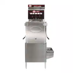
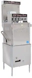
2.1. INTRODUCTION TO THE EST-VL ..................................................................................................... 3
2.1.1. Plumbing Chart ...................................................................................................................... 3
2.2. RECEIVING AND INSTALLATION ...................................................................................................... 4
2.2.1. Electrical ................................................................................................................................ 5
2.2.2. Plumbing ................................................................................................................................. 5
2.2.3. Connecting the Scrap Accumulator and Drain ....................................................................... 6
2.2.4. Straight to Corner Operation Retrofit Instructions. ............................................................... 7
3. OPERATION .................................................................................................. 8
3.1. INITIAL SETUP ................................................................................................................................. 8
3.2. STARTUP PROCEDURES.................................................................................................................... 9
3.3. QUICK SERVICE GUIDE ....................................................................................................................10
4. ADDENDUM FOR MACHINES INSTALLED IN THE CITY OF CHICAGO ............... 11
5. ELECTRICAL DIAGRAM ............................................................................ 12

MODEL EST-VL INSTALLATION & OPERATION MANUAL Rev. 1.00 Page
2
1. Specifications
1.1 EST-VL
WATER CONSUMPTION
PER RACK 1.09 GAL (4.12 L)
PER HOUR 33 GAL (125L)
OPERATING CYCLE
WASH TIME-SEC. 53 53
RINSE TIME-SEC. 30 30
DWELL TIME-SEC.
VENT FAN –SEC.
7
30
7
30
TOTAL CYCLE 120 SEC. 120 SEC.
OPERATING CAPACITY
RACKS PER HOUR 30 30
WASH TANK CAPACITY 1.09 GAL. (4.12 L)
PUMP CAPACITY 52 GPM (196.8 LPM)
WATER REQUIREMENTS
COLD WATER TEMP.
HOT WATER TEMP.
HOT WATER INLET
COLD WATER INLET
DRAIN CONNECTION
40-65°F
140°F
½”
½”
2”
(5-18°C)
(60°C)
1.27 cm
1.27 cm
5.1 cm
OPERATING TEMPERATURE
REQUIRED
RECOMMENDED
120°F
140°F
49°C
60°C
DIMENSIONS
DEPTH 29½” (79.2cm)
WIDTH 25” (64cm)
HEIGHT 85 ¼”-86 ¼” (216-219)cm
MAX CLEARANCE FOR DISHES 20” (43.18 cm)
STRANDARD RACKS 19 ¾” x 19 ¾” (50 x 50 cm)
ELECTRICAL RATINGS
DISHMACHINE
BOOSTER HEATER
VOLTS
115 (1 phase)
240 (3 phase)
AMPS
16
30
WASH PUMP MOTOR
BOOSTER HEATER
1 HP
12KW
SHIPPING WEIGHT
APPROXIMATE 400# (182kg)
METRIC
USA

Getting Started
MODEL EST-VL INSTALLATION & OPERATION MANUAL Rev. 1.00 Page
3
2. Getting Started
2.1. Introduction to the EST-VL
2.1.1. Plumbing Chart
Booster
Heater
Vacuum Breaker
Cold Solenoid
Valve
Hot Solenoid
Valve
Cold Gate Valve
Condenser
Wash
Pump
Hot Gate Valve

Getting Started
MODEL EST-VL INSTALLATION & OPERATION MANUAL Rev. 1.00 Page
4
The EST-VL Dishmachine is safe and easy to operate with its “Auto Start/Stop” and it’s
economical to operate—using only 1.09 gallons of water per cycle and less than 1900 watts of
power when running. The EST-VL Dishmachine’s top mounted controls include built-in chemical
pumps and a deliming system that assures proper chemical usage. Its integrated scrap tray
prevents food soil from entering the drain system. The EST-VL can be run at a rate of 30
racks/120 covers per hour and its heavy-duty stainless steel construction assures long life and
years of trouble free operation.
It is a stand-alone machine featuring a self-contained booster heater. The machine is equipped
with the built in Heat Recovery System which reduces significantly the humidity in the
dishwashing room. The Heat Recovery System uses the heat of the steam generated during the
wash cycles to warm up the in-feed water (41F -65F) before entering the booster heater.
Operation of the EST-VL is automatic. When the door is opened and then closed, the wash cycle
begins automatically. To initially fill the machine daily, press auto fill rocker switch to fill the
booster heater. The booster heater is full when the water begins to flow into the cabinet. Wait for
about 5 minutes and press auto fill rocker switch again to fill the wash tank.
This manual is structured to provide a complete reference guide to the EST-VL Dishmachine. It
is presented in a manner that all users will be able to comprehend and use as an effective tool in
supporting the operation and maintenance of the dishmachine. The first section explains how the
machine is packaged and what to look for when receiving the machine.
After unpacking the machine, this manual explains how to install and set up the machine for use.
Requirements are given for plumbing, wiring, and space considerations. These attributes of the
machine are always taken into consideration by our well-trained sales representatives prior to the
order being placed. In the manual, guidance is also given for installation to ensure that the
machine will be able to run at optimum conditions.
The Operation section of the manual may be used for instruction and procedures when required.
We make this portion of the manual easy to understand so that all levels of operators may be
able to read and comprehend the operation of the machine. The function of the machine itself is
mostly automatic and takes little training to put into full operation. The Operation section also
includes diagnostic considerations (troubleshooting) for the machine when problems occur.
CMA warranties the workmanship of the machine.
We are committed to providing the best machines and customer service in the food industry and
your feedback is welcome.
CMA warranties the workmanship of the machine.
Warning:
Failures to provide soft water (3g or less), will void the machines warranty.
the EST- VL has a Heat Recovery (HR) system comprised of heat exchange coils that
can become restricted or clogged if the water supplied to the machine contains lime scale, known
as hard water conditions. The cold water supplied to the EST- VL should be analyzed and treated
to maintain maximum 3 grains water hardness to prevent scaled conditions. First sign of a
problem will be restricted or zero rinse flow to the rinse arms.
CMA expressly disclaims any and all warranties, express or implied, relating to the installation of any and all CMA equipment that is installed by chemical dealers, contracted servicers or third
party servicers to CMA equipment. If the installation instructions are not followed exactly (to the letter), or, if any person or company conducting the installation of the CMA equipment, revise the
installation procedures or alter the instructions in any manner, the CMA warranty becomes void. If, due to the improper installation of CMA equipment, this equipment ceases to operate properly or
affects other parts of the CMA dishwashing equipment, in that the other parts become defective, the CMA warranty becomes void. CMA will not be liable or responsible or warrant CMA
equipment, due to improper installation of any CMA model dishwasher.
DISCLAIMERS
CMA does NOT
endorse “Tankless On-Demand” water heaters for use on CMA Dishmachine products. On most applications, the
volume of hot water required for commercial dishmachines exceeds the capacity of these types of heating sources. You will find
that most, if not all, commercial dishmachines have been programmed with auto-filling features that require quick filling, with a
designated limited time.
CMA
DOES endorse, and highly recommends, the standard “tank” style water heaters, sized properly to handle each particular
facility with their water heating requirements. A “tank” style water heater stores and supplies a large capacity of preheated water
before providing hot water to the dishmachine. To meet required health codes, there must be a reliable and consistent flow of
adequate hot water supplied to the dishmachine. If the facilities’ “tank” style water heater is marginal in size, CMA recommends
installing a proper size Hatco Booster Heater, a CMA’s E-Temp 40 or 70-degree-rise Booster Heater (that can be installed on CMA
Conveyors), or a CMA Temp-Sure Booster Heater (for door and undercounter dishmachines). All are designed to adequately
achieve results.

Getting Started
MODEL EST-VL INSTALLATION & OPERATION MANUAL Rev. 1.00 Page
5
2.2. Receiving and Installation
The dishwasher is shipped from the factory in a corrugated box on a wooden pallet. The
installation guidelines give a systematic procedure for setting up the machine.
Start by removing the dishmachine from the box. Remove the packaging, unwrap the machine
and check for the following components:
Inside the wash tank is a plastic bag with one control box key and a cam timer
wrench.
Tube stiffeners must be used to prevent the feed tubes from curling inside the
chemical pail and sucking air. These are located on the outside of the machine with
the chemical tubing already installed into the stiffeners. The ends of the chemical
tubing have been flared so that the tubing will not pull out of the stiffener. Red is for
detergent, white for sanitizer, and blue for rinse aid.
2.2.1. Electrical
*
Prior to installation make sure the electrical supply is compatible with the specifications on the
machines data plate.
The EST-VL dishmachine and the booster heater must be hard wired directly to a proper
dedicated 115 VAC, 60Hz and 240VAC,60Hz circuits equipped with proper circuit protection. The
main power switch is at the top-right side of the control box.
WARNING: Electrical and grounding connections must comply with the applicable portions of the
National Electrical Code and/or other local electrical codes.
Note: For supply connections, use copper wire only rated at 90 degree C minimum.
2.2.2. Plumbing
*
The water supply connection is made with a ½” hot water line to the water supply inlet on the top
of the machine. The water supplied to the machine is recommended to be 140° F. The time
necessary to deliver water to the machine is controlled by the number four cam. This cam
*
Electrical and plumbing connections must be made by a qualified person who will comply with all
available Federal, State, and Local Health, Electrical, Plumbing and Safety codes

Getting Started
MODEL EST-VL INSTALLATION & OPERATION MANUAL Rev. 1.00 Page
6
provides the serviceman with the opportunity to fine tune the machine to deliver the proper
amount of water with each cycle.
Note: The required flowing water pressure to the dishwasher is 15-65 PSIG. If pressures higher
than 65 PSIG are present, a pressure regulating valve must be installed in the water line to the
dishwasher (by others). If flowing pressure is lower than 15 psi, improper machine operation may
result.
The EST-VL Dishmachine has a 2” drain. The following section explains how to connect the
drain.
Notice to Plumber: The plumber connecting this machine is responsible for making certain that
the water lines are THOROUGHLY FLUSHED OUT BEFORE connecting to the dishwasher
Ask your municipal water supplier for details about your local water conditions prior to installation.
Recommended water hardness is 3 grains per gallon or less.
Note: high iron levels in the water supply can cause staining and may require an iron filter. High
chlorine levels in the water supply can cause pitting and may require a chloride removal system.
If an inspection of the dishwasher or booster heater reveals lime buildup after the equipment has
been in service, water treatment is recommended. If water softener is already in place, ensure
there is a sufficient level of salt.
2.2.3. Connecting the Scrap Accumulator and Drain
The scrap accumulator is designed to perform two basic functions:
1. It allows a method to discharge all the heavy solids out of the machine with each
wash cycle.
2. It provides accumulation capacity to allow draining the contents of one cycle
regardless of the discharge rate of the existing drain.
The drainpipe is connected to the scrap accumulator drain using a 2” no-hub connector as shown
in
Figure 2.2.3 below.
2" DRAIN
SLEEVE
2"
NO-HUB
2" DRAINPIPE
SCRAP ACCUMULATOR
HOSE
CLAMPS
Figure 2.2.3
Getting Started
MODEL EST-VL INSTALLATION & OPERATION MANUAL Rev. 1.00 Page
7
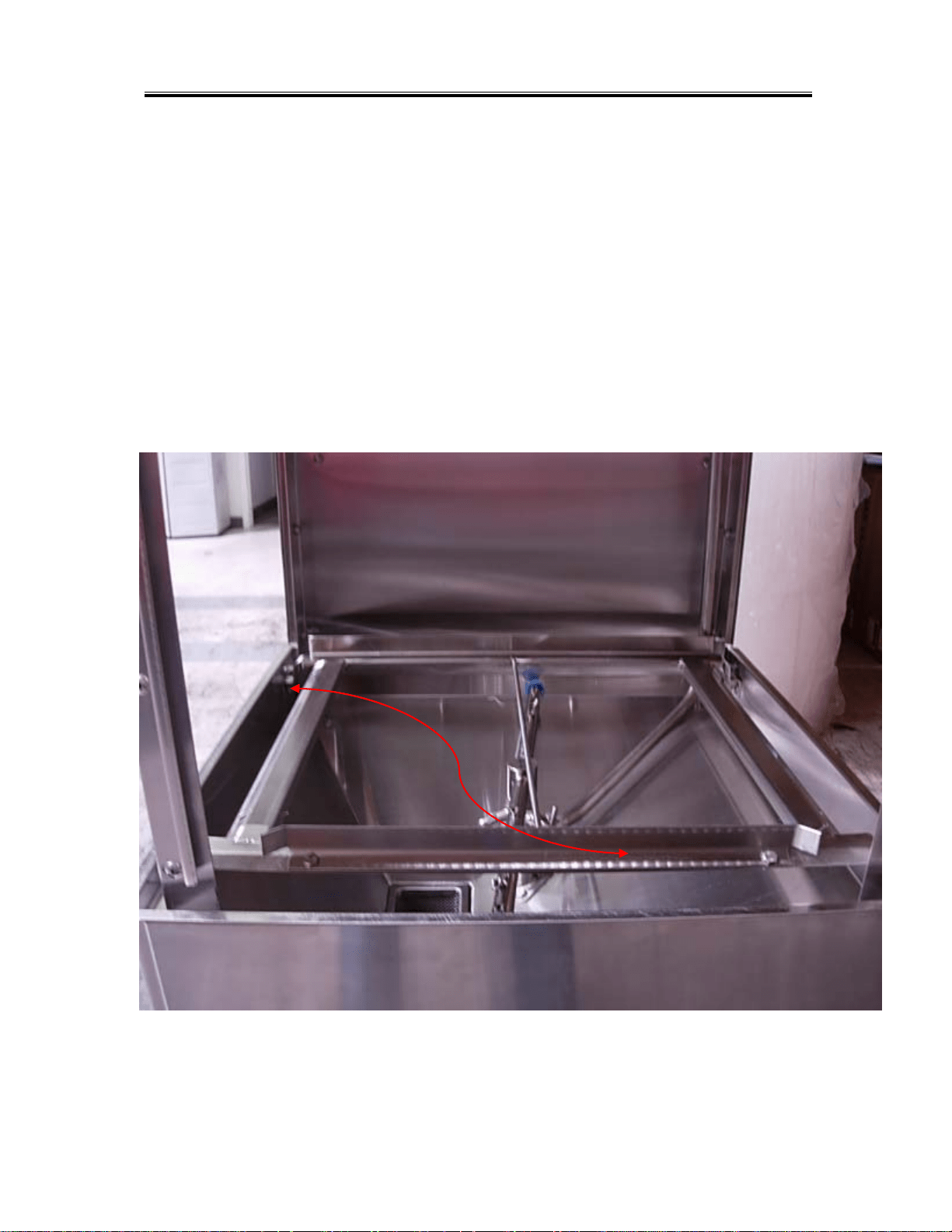
2.2.4. Straight to Corner Operation Retrofit Instructions.
In order to convert machine from straight to corner application,
you will need to relocate the tray track rail from straight to corner
position (see red line on the photo) and then mount it on the tray
track using the same bolts, washers and lock nuts used for straight
application.

Operation
MODEL EST-VL INSTALLATION & OPERATION MANUAL Rev. 1.00 Page
8
3. Operation
3.1. Initial Setup
All machines are equipped with switches to prime the peristaltic pumps at anytime the master
switch is "ON".
Following completion of the installation, always fill the machine with water before starting the
machine.
1. With the power “ON” hold the fill button until the water level overflows into the scrap
accumulator.
2. Check the chemical lines to the chemical containers.
a. Red: detergent line.
b. Blue: rinse agent line.
c. Clear/White: sanitizers line.
3. Activate the prime switches for the three chemical pumps until product is
discharging into the machine.
Note: Use only commercial-grade detergents and rinse aids recommended by your
chemical professional. Do not use detergents and rinse aids formulated for
residential dishwashers.
Low Temperatures chemical-sanitizing dishmachines must not exceed 6% sodium
hypochlorite solution (bleach) as the sanitizing agent. Higher levels may damage
stainless or components.
Follow the directions precisely that are on the litmus paper vial and test the water on
the surface of the bottom of the glasses. Concentration should be 50 p.p.m.
minimum to 100 p.p.m. maximum. If concentration is incorrect contact your
chemical supplier.
4. To start the machine, close the doors - this will automatically start the machine. The
machine will run through its cycle.
5. Operate the machine one cycle and watch to ensure that the chemicals are
delivered and stop during the cycle. Remember: red tube - detergent: blue tube -
rinse: and clear/white tube - sanitizer. Check temperature at the end of the cycle for
140°F, 60°C.
The amount of product delivered by each cam is controlled by adjusting the cam’s
opening. When the micro switch rides down into the cam the peristaltic pump motor
begins to rotate. It will continue to rotate until it rides up out of the groove.
Therefore, to extend the amount of product delivered to the machine, open the
grove; to reduce the amount of product delivered to the machine, close the groove.
The cams are slip fit and a cam adjustment wrench is provided.
CAUTION: The motors on the new peristaltic pumps may be stalled by excessive tightening of
the cover plate screws. If a peristaltic pump does not turn when the micro switch is activated,
loosen the screws on the cover plate.
Technical personnel are available during normal business hours at CMA Headquarters should
you, as an installer, have any questions, please call 800-854-6417.

Operation
MODEL EST-VL INSTALLATION & OPERATION MANUAL Rev. 1.00 Page
9
3.2. Startup Procedures
Please follow the instructions given here before each shift to assure trouble free operation.
2. Drain the water if it is cold by activating the drain switch until all the water is
out of the machine.
3. Check the drain screen and, if needed, remove it from the machine and clean
it out. After cleaning, replace it properly into the sump housing.
4. Check the wash arm spray tips. If they are clogged, clean them with a
toothpick and rinse them at the sink. Replace the wash arms.
5. Press and hold the fill switch until the water overflows into the scrap
accumulator.
6. Once a proper water level is established, check the temperature of the water
(it should be approximately 140°F, 60°C).
7. Insert the tray of dishes into the machine and close the doors. The machine
will automatically start when the doors are closed.
8. After the machine stops, raise the doors, remove the tray of dishes and allow
to dry before stacking.
If the doors are lifted during a cycle, the machine will automatically stop running.
The EST-VL will run through the wash and rinse cycles automatically feeding the proper
chemicals and then turn itself off.
In an emergency you can turn off the machine by turning off the master switch located on the side
of the control box.
Do not open the doors until the machines cycle light has turned off.
Warning:

Operation
MODEL EST-VL INSTALLATION & OPERATION MANUAL Rev. 1.00 Page
10
3.3. Quick service guide
MODEL: EST
TECHNICAL ISSUE
Cause
Solution
Machine starts while doors are
open
Faulty safety door switch
Replace the switch, P/N 00562.00
Faulty start/fill switch
Replace the switch, P/N 03470.01
Faulty #1 micro switch (start/stop)
Replace micro switch, P/N 00411.00
Continuous cycles
Faulty start/fill switch
Replace micro switch, P/N 00421.40
Faulty safety door switch
Replace the switch, P/N 00562.00
Delimer switch in wrong position
Switch to
NORMAL
position
Wash motor runs continuously
Faulty delime switch
Replace the switch, P/N 00475.00
Faulty motor contactor
Replace contactor, P/N 00404.82
Delimer switch on wrong position
Switch to
NORMAL
position
Sanitizer pump does not run
Faulty delimer switch
Replace the switch, P/N 00475.00
Faulty # 6 micro switch
Replace micro switch, P/N 411.00
Faulty sanitizer pump motor
Replace the motor, P/N 00416.00
Broken Spring
Replace spring, P/N 00105.82
Drain valve does not operate
Faulty #3 Micro switch
Replace micro switch, P/N 00411.00
Faulty drain motor
Replace drain motor, P/N 00104.82
Faulty #4 micro switch (Fill)
Replace micro switch, P/N 00411.00
Debris inside water solenoid valve
Clean valve replace diaphragm kit,
P/N 00707.00
Machine does not fill
Faulty start/fill switch
Replace the switch, P/N 03470.01
Drain not closing
check function of drain sys.
Faulty water solenoid coil/valve
Replace coil/valve, P/N 00738.10 or
03603.10
Faulty check valve
Replace valve, P/N 00718.00
Water leaks out of vacuum breaker
Low incoming water pressure
Increase water pressure to 20 psi
Faulty vacuum breaker kit
Replace vac. Brkr kit, P/N 03623.00
Machine only runs when start/fill
switch is depressed
Faulty #1 micro switch (start/stop)
Replace micro switch, P/N 00411.00
Faulty door switch
Replace door switch, P/N 00562.00
Will not start/ nothing works
Wall breaker tripped
Reset breaker
Master on/off switch faulty or in off
position
Reset or replace switch, P/N 00471.10
Runs, but none of the other
functions engage
Faulty #2 Micro switch (cycle
reset)
Replace micro switch, P/N 411.00
Faulty ice cube relay (yellow relay)
Replace relay, P/N 00636.00

MODEL EST-VL INSTALLATION & OPERATION MANUAL Rev. 1.00 Page
11
4. Addendum for Machines Installed in the City of Chicago
"All food dispensing EST-VLablishments using chlorine or other approved chemical sanitizers
shall, at all times, maintain an adequate tEST-VLing device."
"Dishes and other eating and drinking utensils to be washed in a dishwashing machine shall be
properly scraped and pre-rinsed and shall be stacked in racks or trays so as to avoid
overcrowding, and so as to permit the wash and rinse waters to reach all surfaces of each
utensil."
"In machine washing, multi-use eating and drinking utensils shall be washed in water containing a
suitable detergent at a temperature from 120 degrees F. to 140 degrees F. or other method
approved by the Department of Health.
"The water in the wash tank shall be changed during operation as often as is necessary to keep it
reasonably clean. An effective concentration of detergent in the wash water shall be maintained
at all times."
"Bactericidal treatment shall consist of exposure of all surfaces of dishes and utensils being
washed to a rinse of clean water, at a temperature of not less than 180 degrees F. or other
method approved by the Department of Health."
"All dishwashing machines shall maintain a flow pressure not less than 15 or more than 25
pounds per square inch on the fresh water line at the machine and not less than 10 pounds per
square inch at the rinse nozzles. A suitable gauge cock shall be provided immediately upstream
from the final rinse spray to permit checking the flow of the final rinse water. An easily readable
thermometer accurate to ± 2 degrees F. shall be provided on both the wash and rinse water lines
of the dishwashing machine which will indicate the temperature of the water solution therein."
"Dishwashing machines shall be thoroughly cleaned at least once each day. The pumps and the
wash and rinse sprays or jets shall be so designed that a forceful stream of water will reach all
surfaces of the utensils when they are properly racked. These parts shall be thoroughly cleaned
at least once each day. The pumps and the wash and rinse sprays or jets shall be so designed
that a forceful stream of water will reach all surfaces of the utensils when they are properly
racked. These parts shall be readily accessible for inspection and cleaning."
"After bactericidal treatment, utensils and containers shall be stored at a sufficient height above
the floor in a clean, dry place, protected from flies, splash, dust, overhead leakage and
condensation, and other contamination. Containers and utensils shall be inverted, covered, or
otherwise protected from contamination until used for serving."
Drain racks, trays, and shelves shall be made of non-corrodible material and shall be kept clean.
In handling containers and utensils the surfaces thereof which come in contact with food or drink
shall not be touched by the hands, except during the process of washing.
Tables for clean and dirty dishes and food shall be so arranged that the dirty dishes will be as far
removed from the food and clean dishes as may be possible.
All single-service articles and utensils shall be purchased in sanitary cartons and stored therein in
a clean, dry place until used, and after removal from the cartons, these articles shall be handled
in such a manner as to prevent contamination.
Please note the following procedures must be followed for City of Chicago
Approval:
1. All low energy models must have low-level sani alarms, both
visual and audio.
2. All models must have a City of Chicago approval data label
affixed to the machine.
3. Chlorine sanitizer must be a minimum of 100 PPM.

Electrical Diagram
MODEL EST-VL INSTALLATION & OPERATION MANUAL Rev. 1.00 Page
12
5.
Electrical Diagram
POWER
BOOSTER
HEATER
CONTACTOR
T
1
T
2
T
3
L
1
L
2
L
3
12kW
BOOSTER
HEATER
ADJ.
THERMOSTAT
HI LIMIT
SWITCH
ROCKER
SWITCH
2 13
8
7
ON
OFF
SANI SWITCH
DET SWITCH
RINSE SWITCH
PUMP
MOTOR
NC
NO
C
1 4
8
5
9
1
2
1
4
1
3
COUNTER
L
1
T
1
115 VAC
NEUTRAL
GND
DELIME
NORMAL
WATER
SOLENOID
VALVE
RINSE
SANI
DET
DRAIN
SOLENOID
VALVE
1
2 3 4 5
6 7 8
FILL / START
SWITCH
RUNNING
LIGHT
DOOR
SAFETY
SWITCH
WASH PUMP
CONTACTOR
POWER
SWITCH
POWER
BLOCK
8 CAM TIMER
START /STOP
RELAY
23
8
9
FAN
MOTOR
230 VAC 3 Phase
10
DSI
Solenoid
1
2
3
NC
NO
C
1 2
4
3
5
6
8
7
CONDENSER
FLUSH
VALVE
CONDENSER FLUSH
DRAIN SWITCH