
www.cmadishmachines.com
Table of Contents
EST-44
1. SPECIFICATIONS................................................................................................. 2
1.1. EST- 44 ........................................................................................................................................... 2
2. GETTING STARTED ............................................................................................ 3
2.1. Introduction to CMA Model EST -44............................................................................................. 3
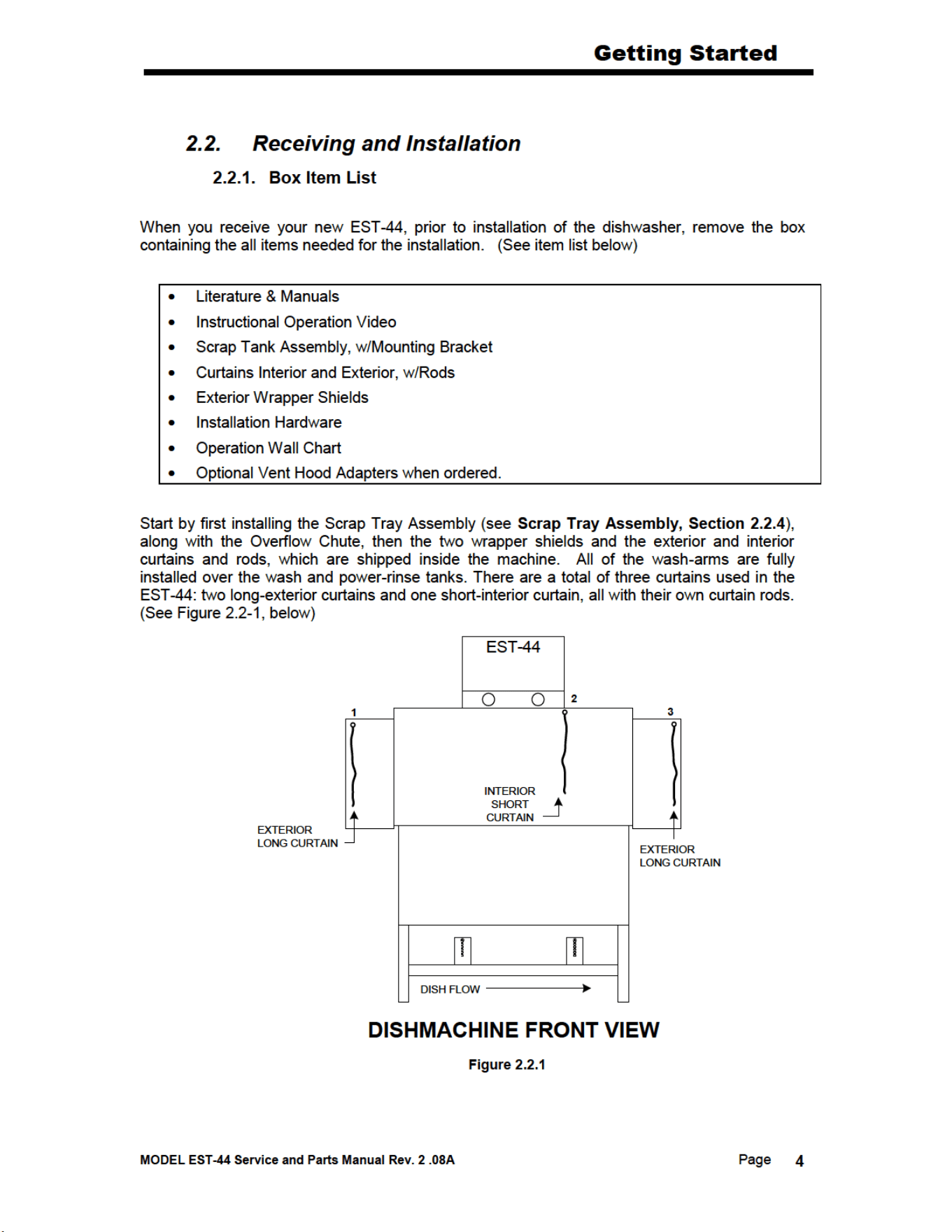
2.2. Receiving and Installation .............................................................................................................. 4
2.2.1. Box Item List ........................................................................................................................... 4
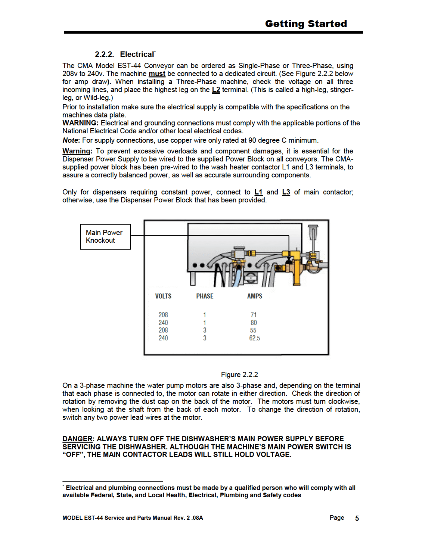
2.2.2. Electrical ................................................................................................................................ 5
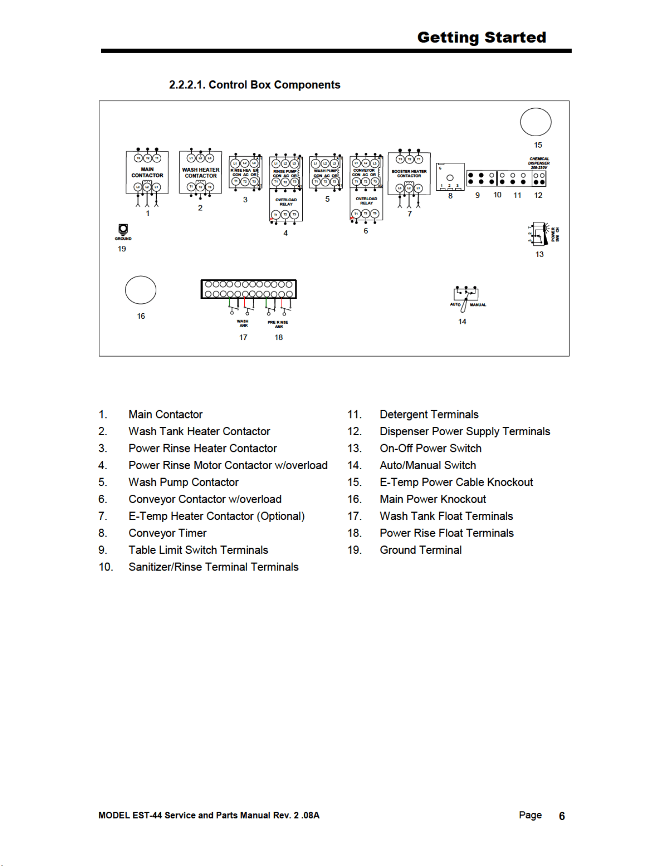
2.2.2.1. Control Box Components ............................................................................................... 6
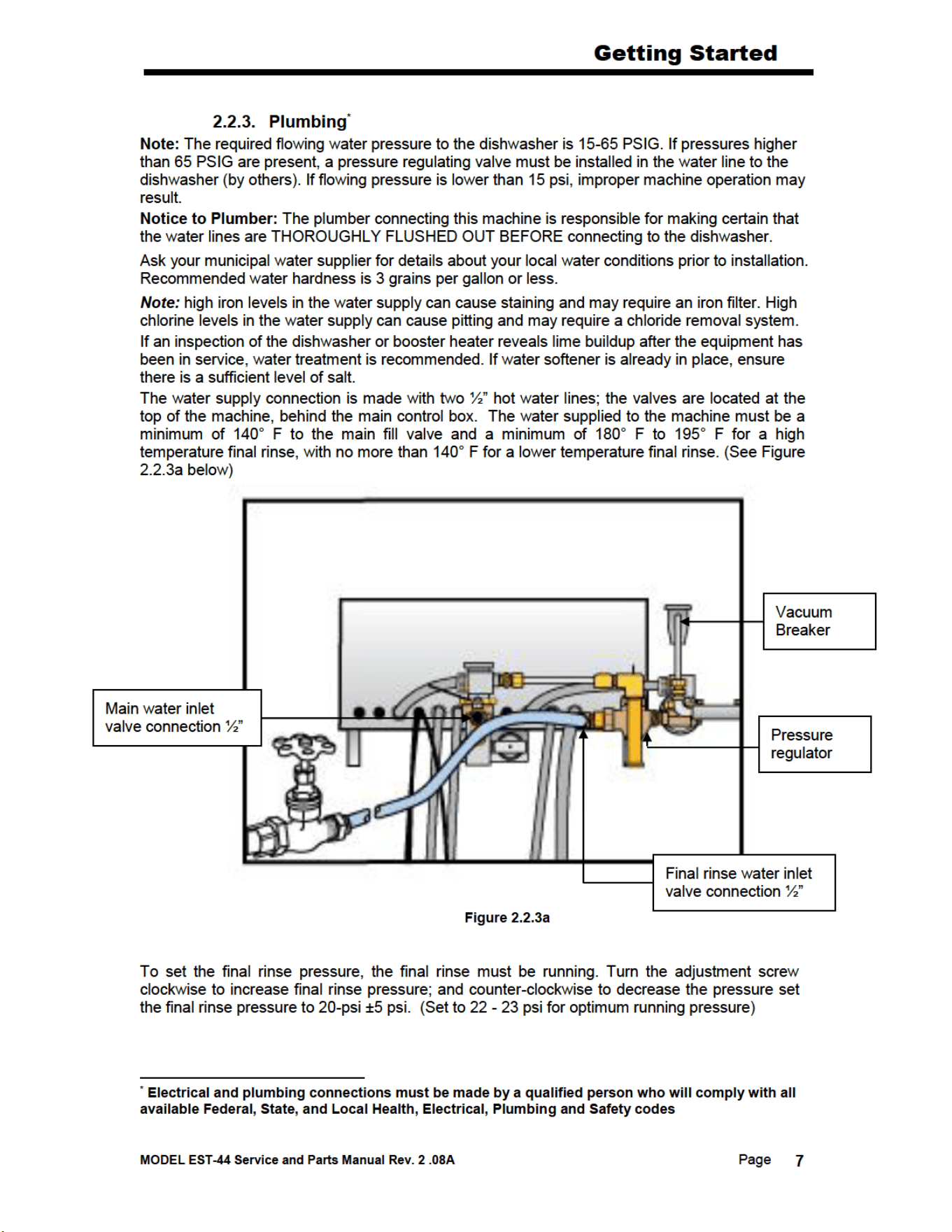
2.2.3. Plumbing ................................................................................................................................. 7
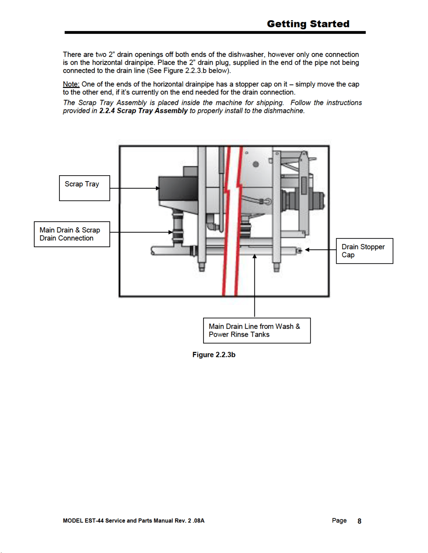
2.2.4. Scrap Tray Assembly Installation ........................................................................................... 9
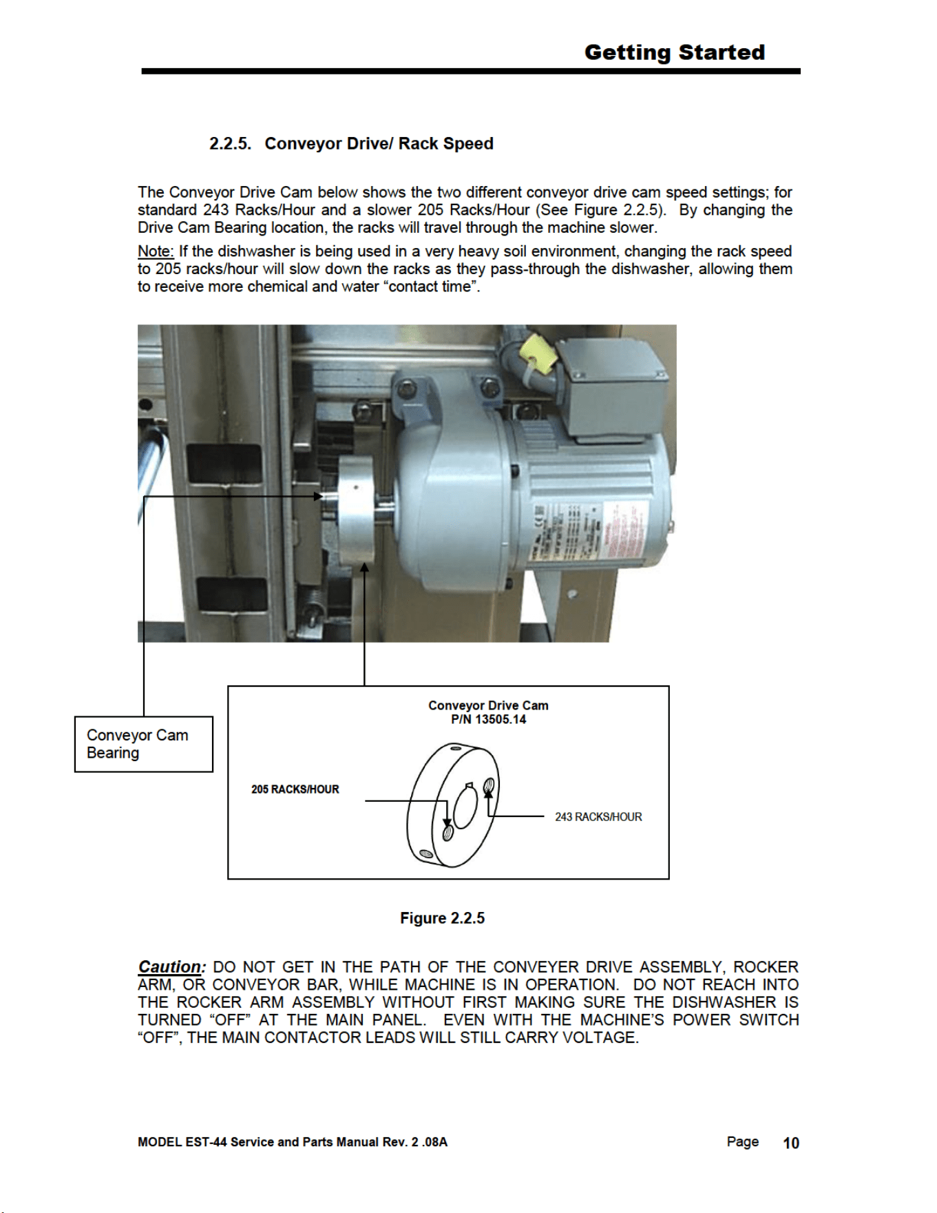
2.2.5. Conveyor Drive/ Rack Speed .................................................................................................10
2.2.6. Wash Pump Assembly and Impeller .......................................................................................11
2.2.7. Table Limit Switch Installation ..............................................................................................12
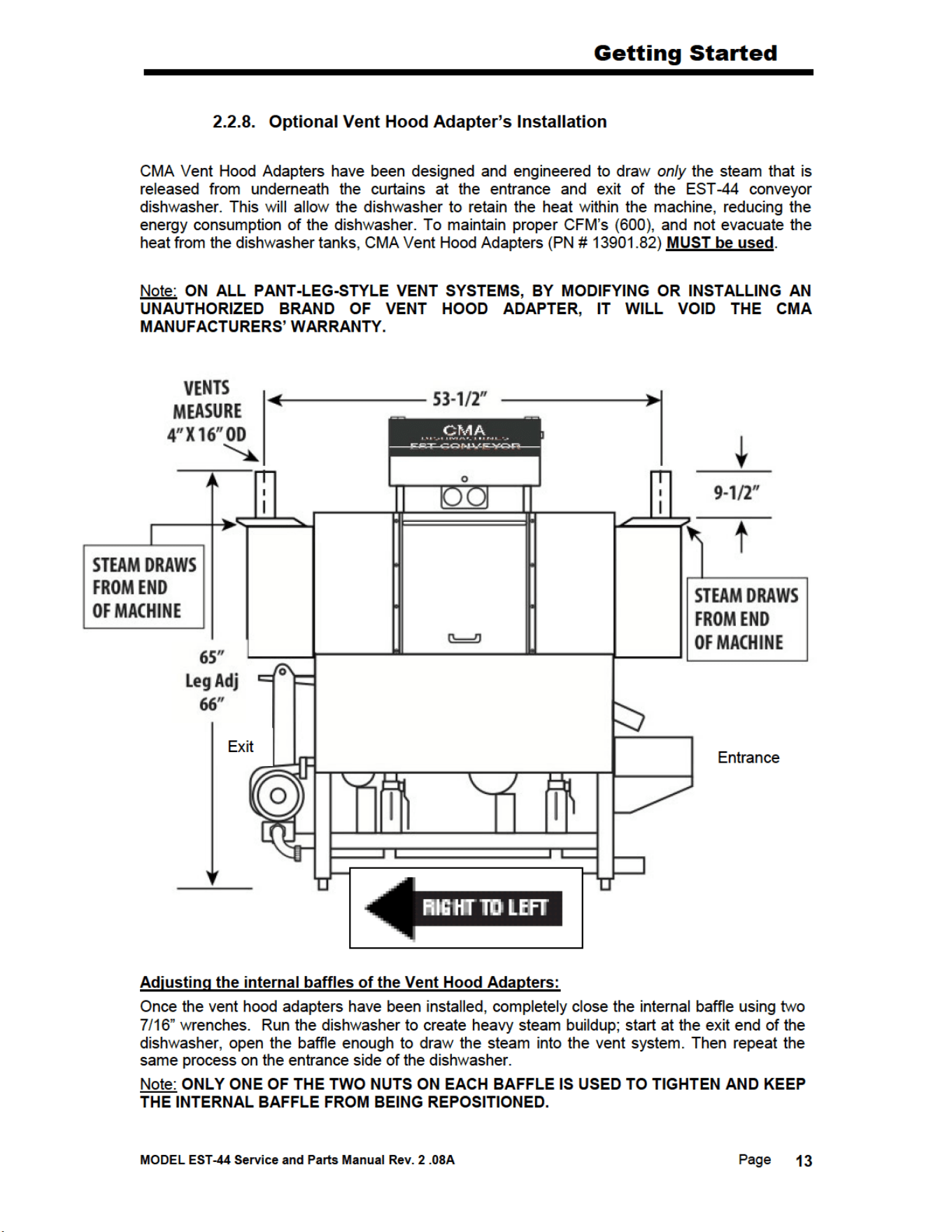
2.2.8. Optional Vent Hood Adapter’s Installation ...........................................................................13
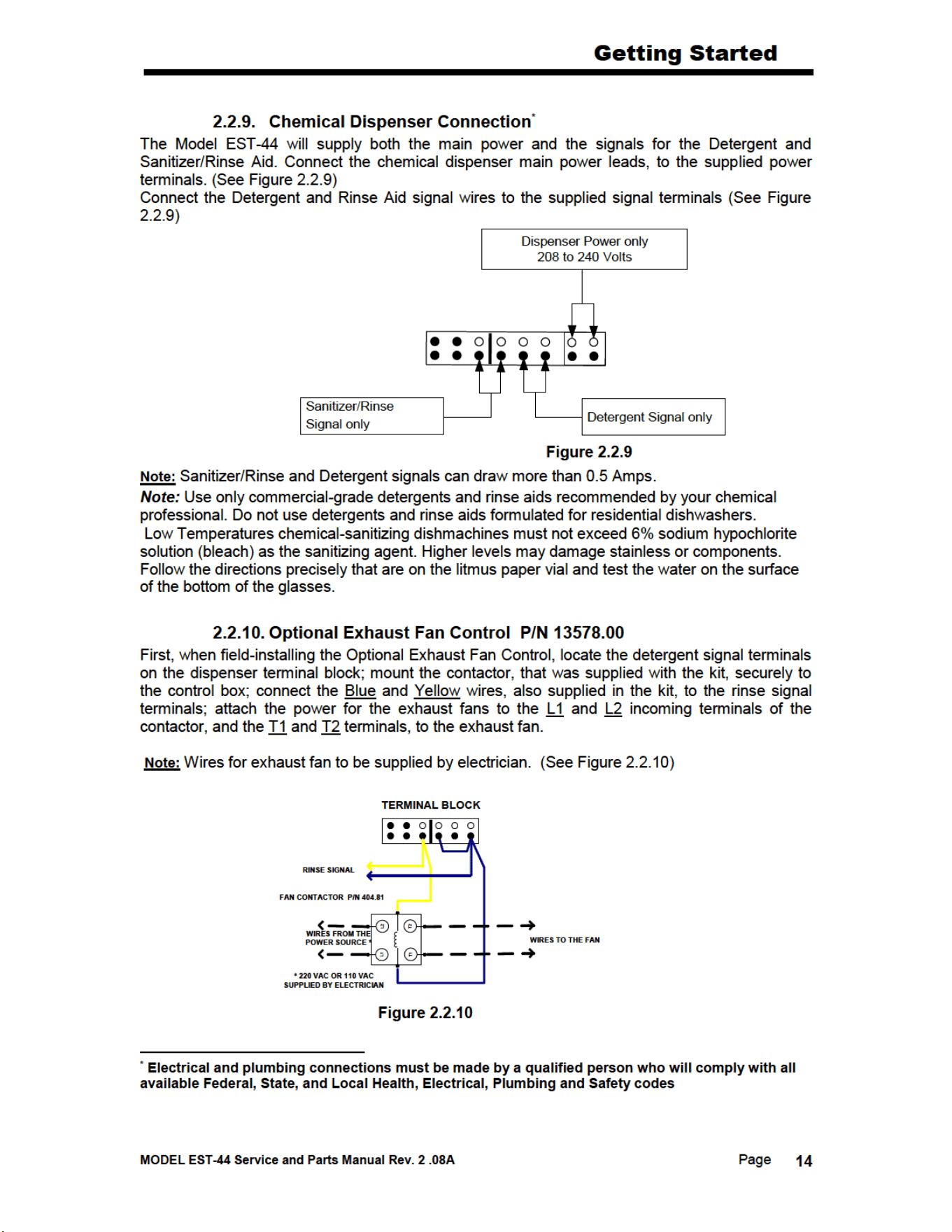
2.2.9. Chemical Dispenser Connection ...........................................................................................14
2.2.10. Optional Exhaust Fan Control P/N 13578.00 ......................................................................14
2.2.11. (Optional) E-Temp Booster Heater .......................................................................................15
2.3. EST-44 Safety Tips .......................................................................................................................16
3. OPERATION ........................................................................................................ 17
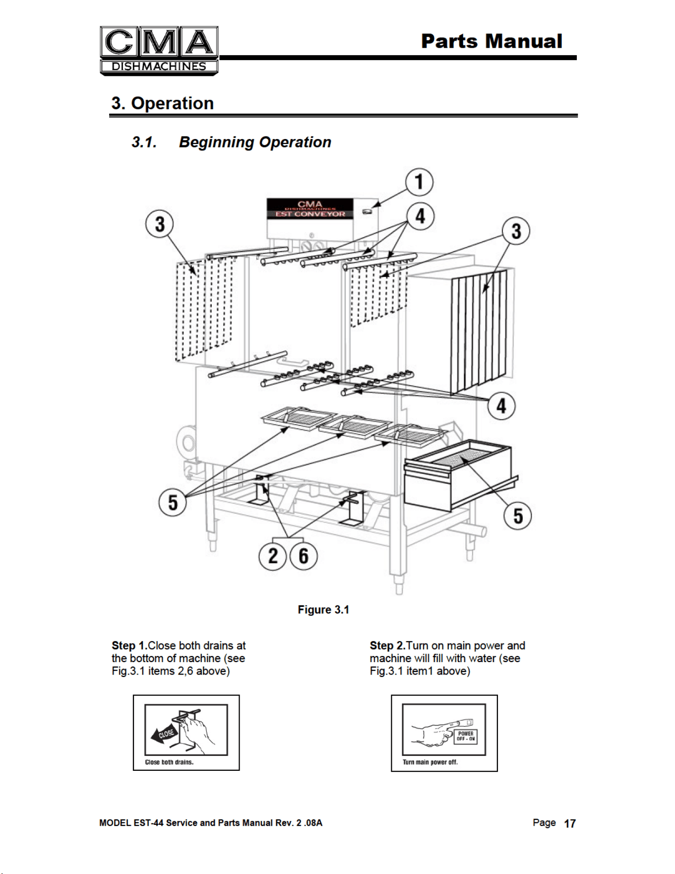
3.1. Beginning Operation ......................................................................................................................17
3.2. Cleaning Instructions .....................................................................................................................19
3.3. Regular Service and Maintenance Checklist .................................................................................20
3.4. Trouble Shooting ...........................................................................................................................21
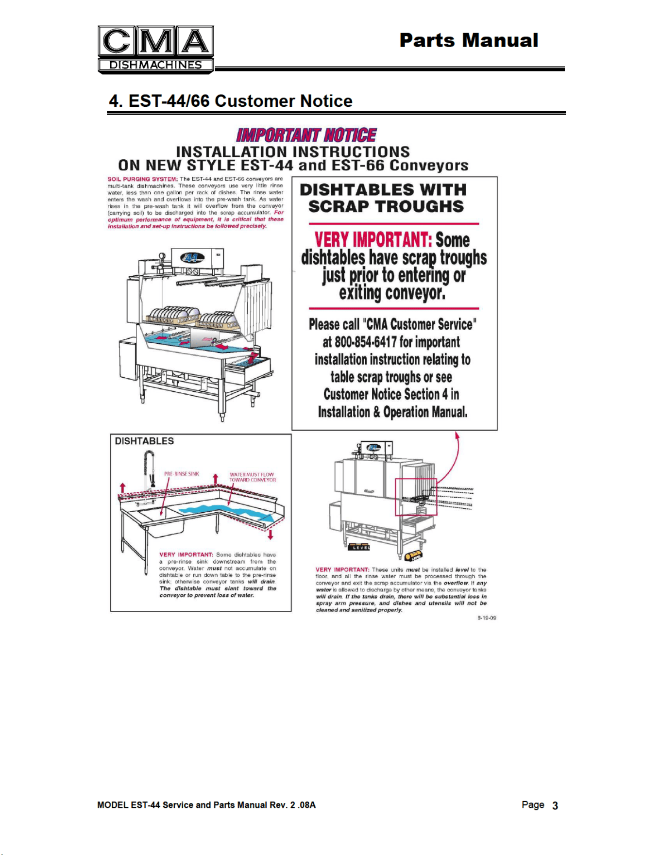
4. EST-44/66 CUSTOMER NOTICE ........................................................................ 3
5. PARTS MANUAL .................................................................................................. 5
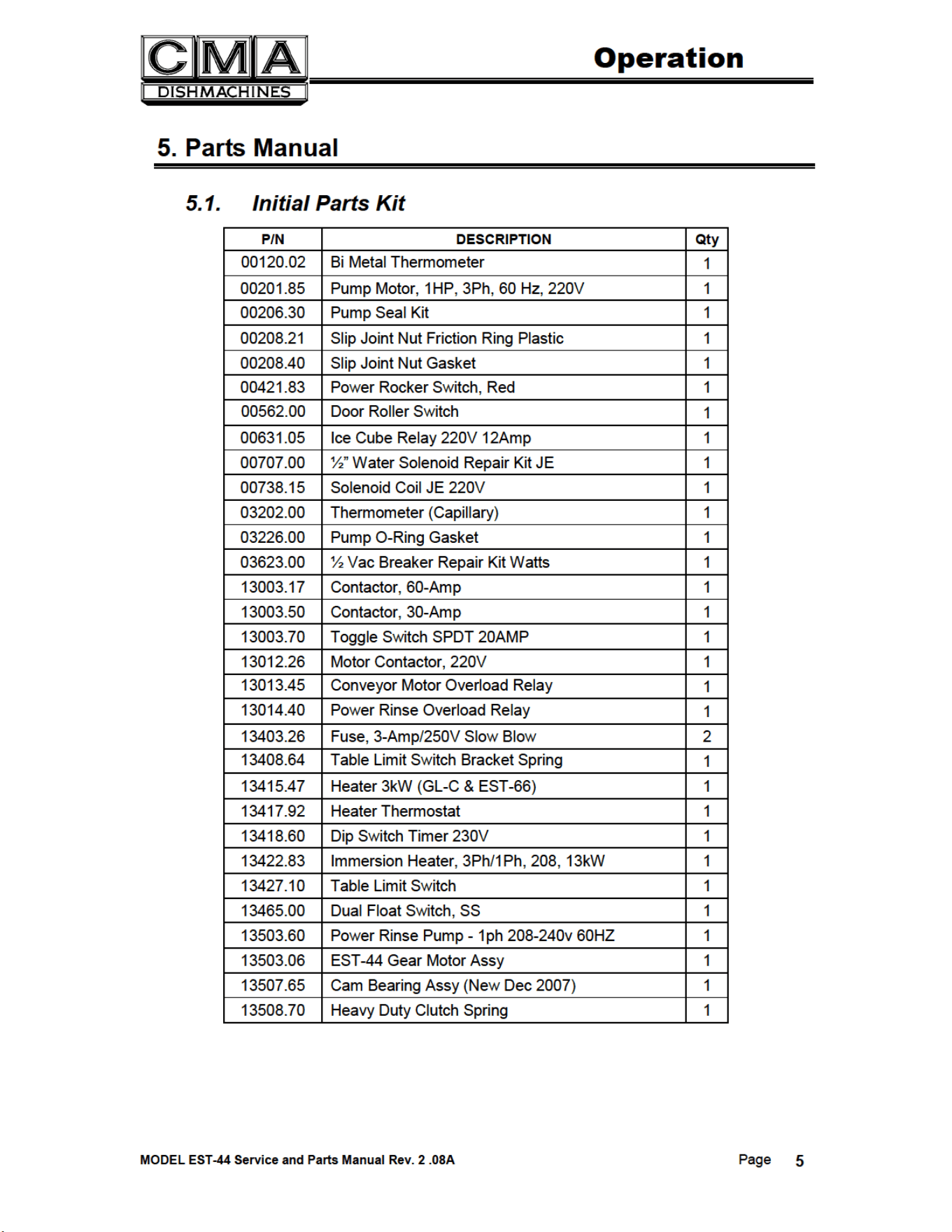
5.1. Initial Parts Kit ............................................................................................................................... 5
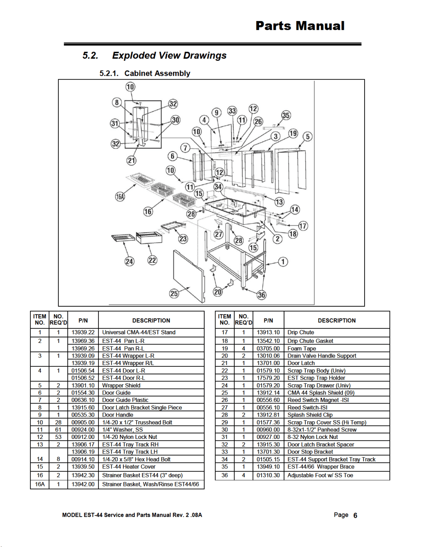
5.2. Exploded View Drawings ............................................................................................................... 6
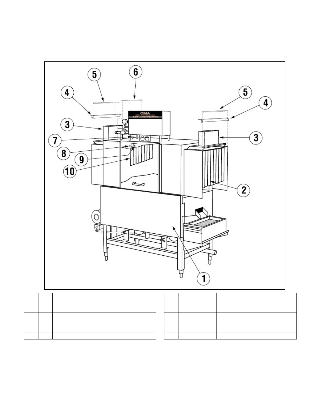
5.2.1. Cabinet Assembly ................................................................................................................... 6
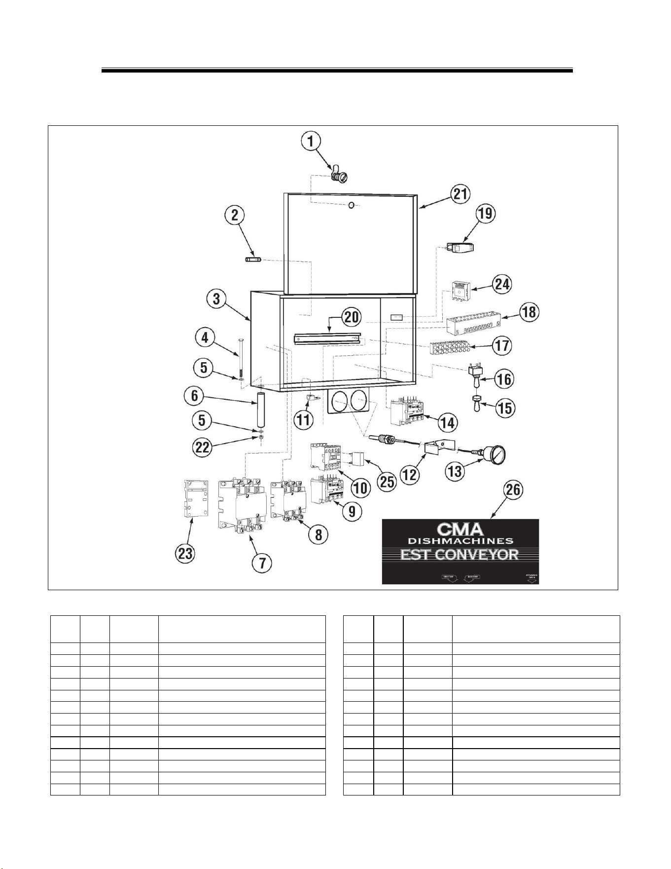
5.2.2. Control Box Assembly (3 Phase) ............................................................................................ 7
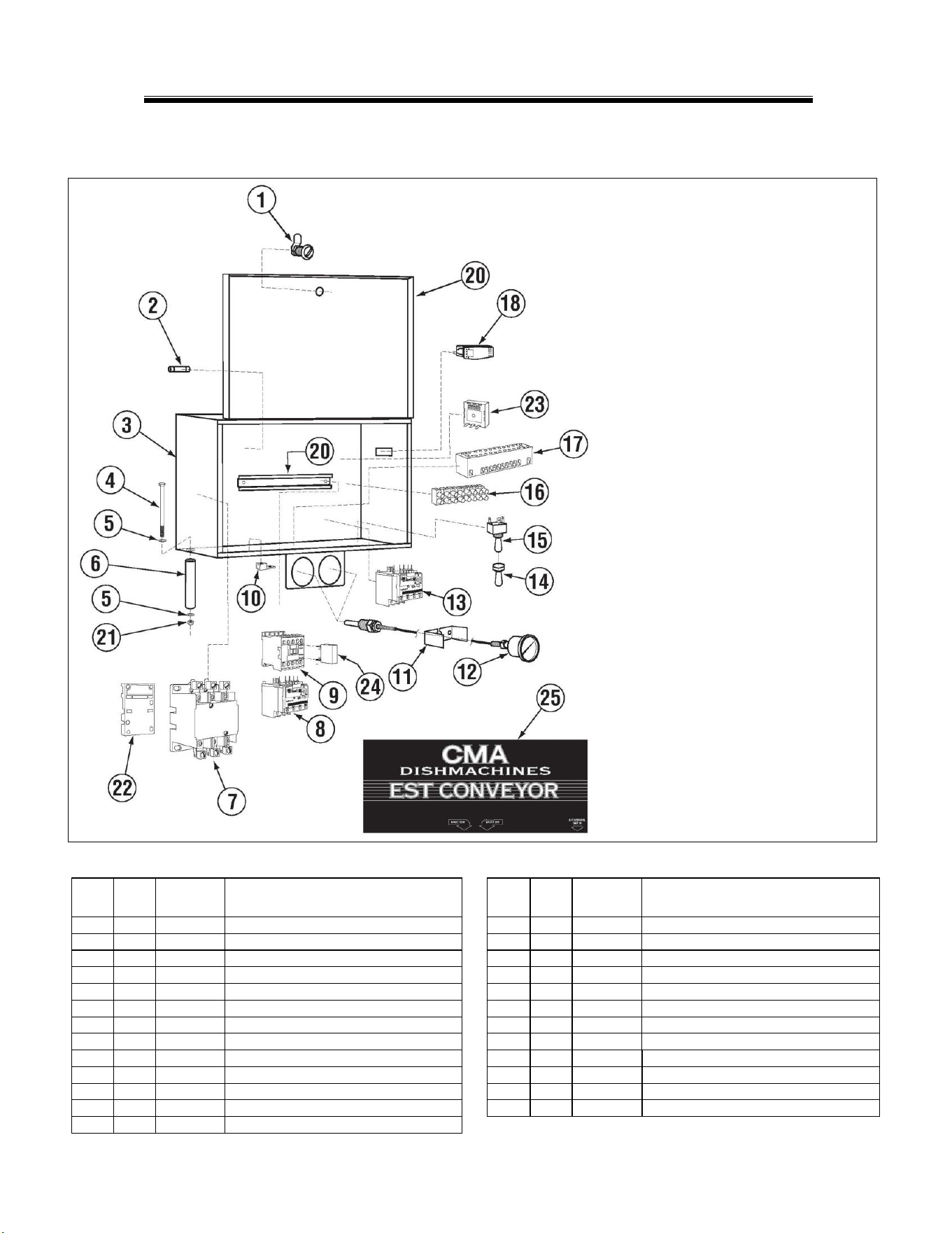
5.2.1. Control Box Assembly (1 Phase) ............................................................................................ 8
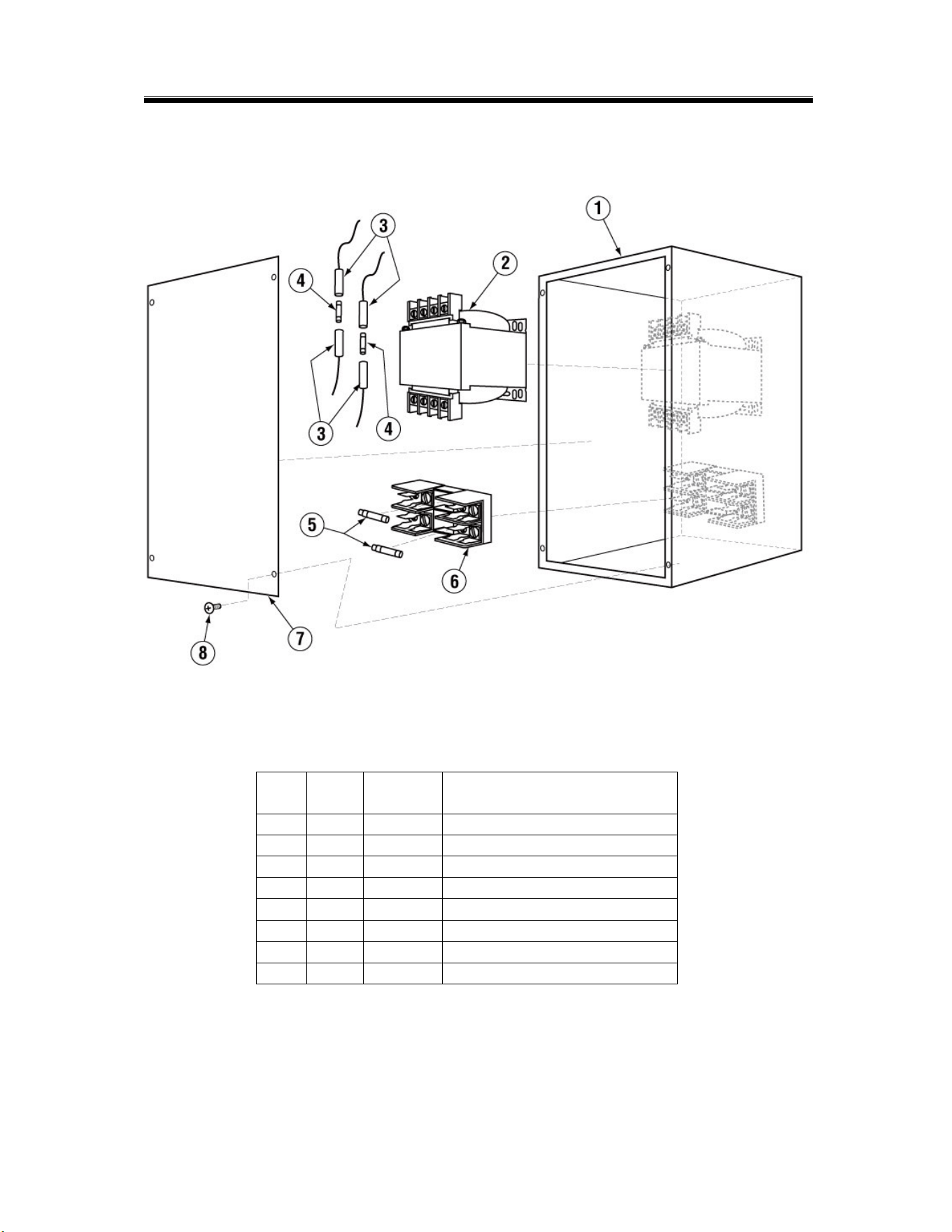
5.2.2. 480V Control Box Assembly (480V machines only) ............................................................... 9
5.2.3. Curtain and Optional Vent System ........................................................................................10
5.2.4. Old Wash Temperature Control System (Square Flange) .....................................................11
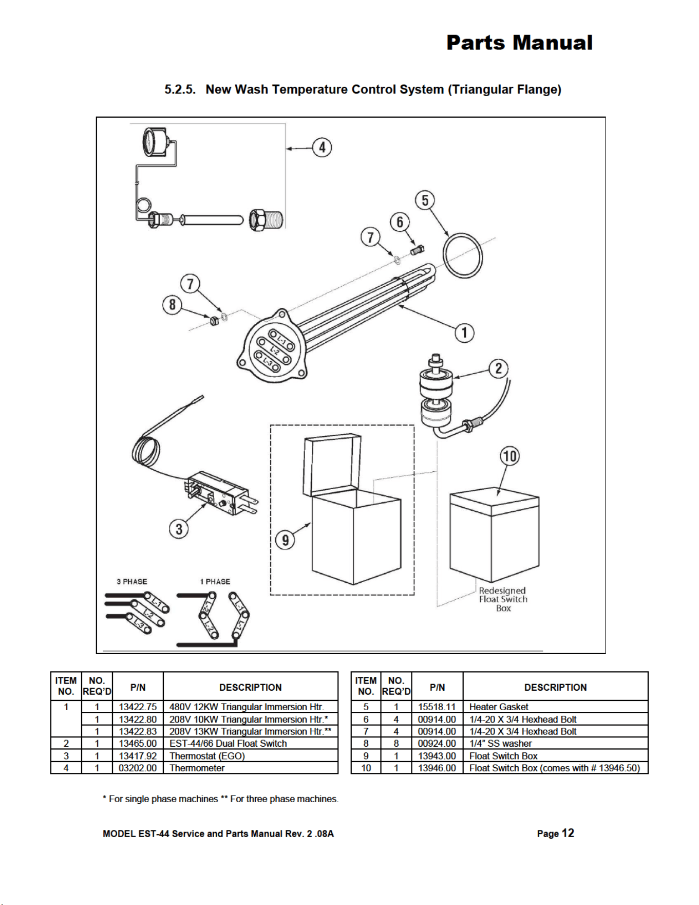
5.2.5. New Wash Temperature Control System (Triangular Flange) ..............................................12
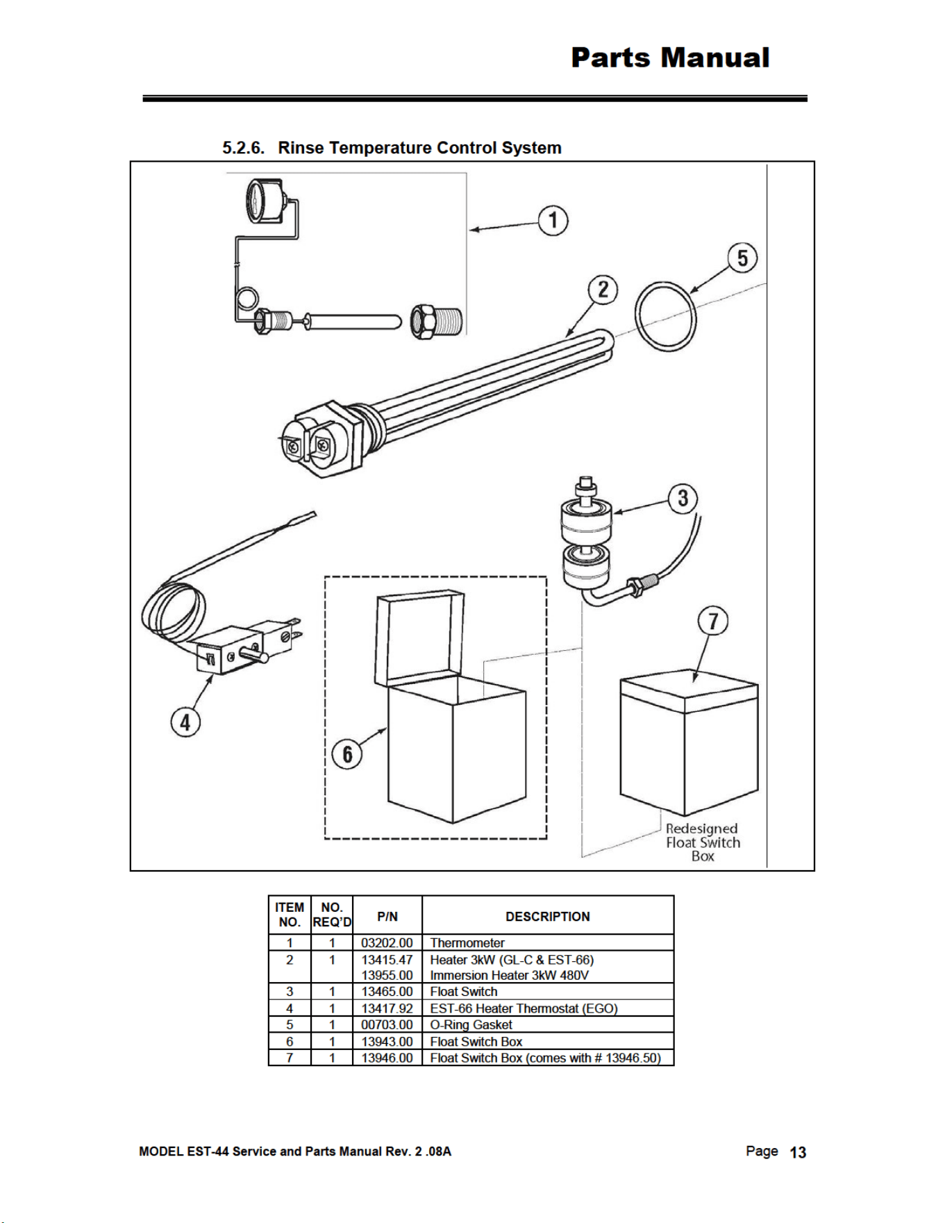
5.2.6. Rinse Temperature Control System .......................................................................................13

www.cmadishmachines.com
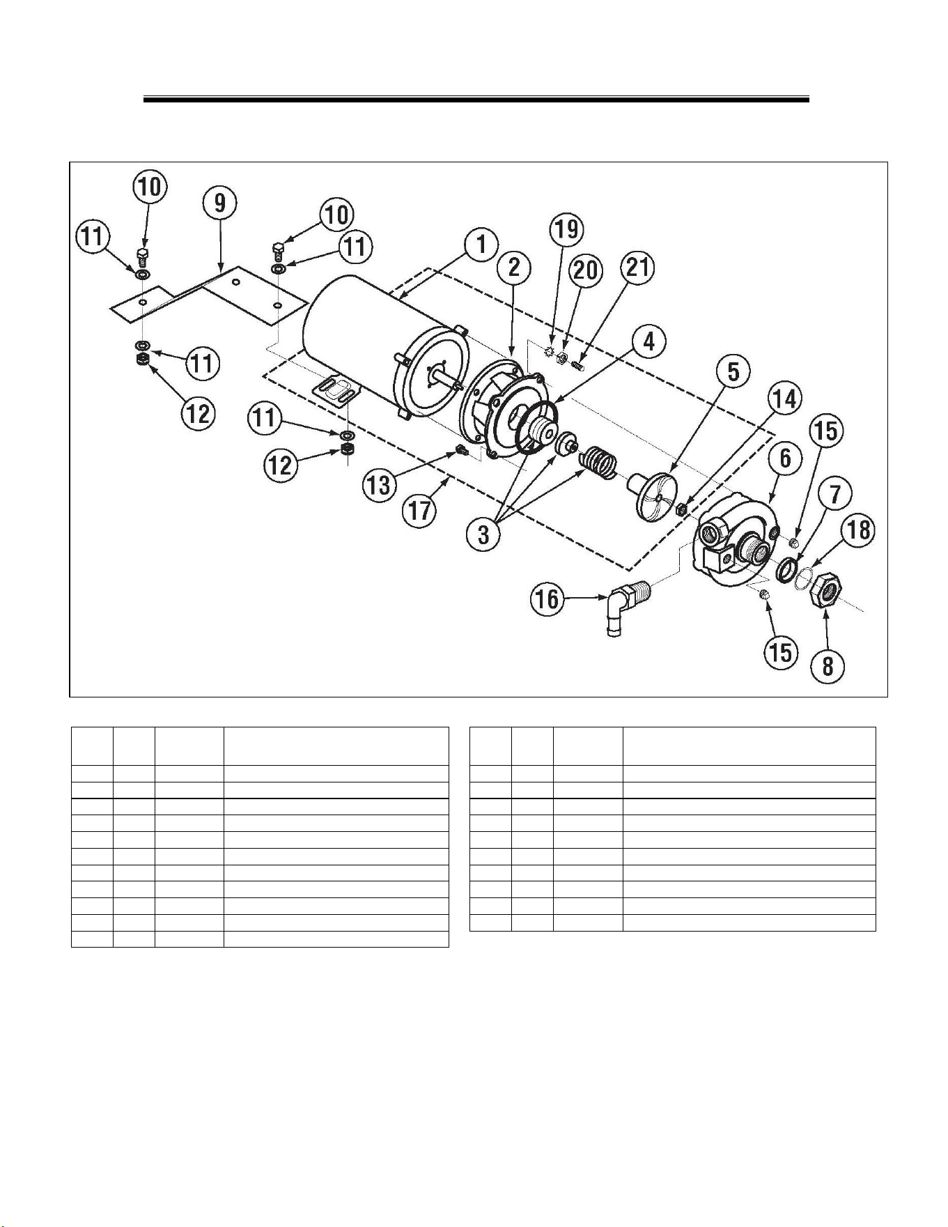
5.2.7. Wash Pump Assembly (3 Phase) ............................................................................................14
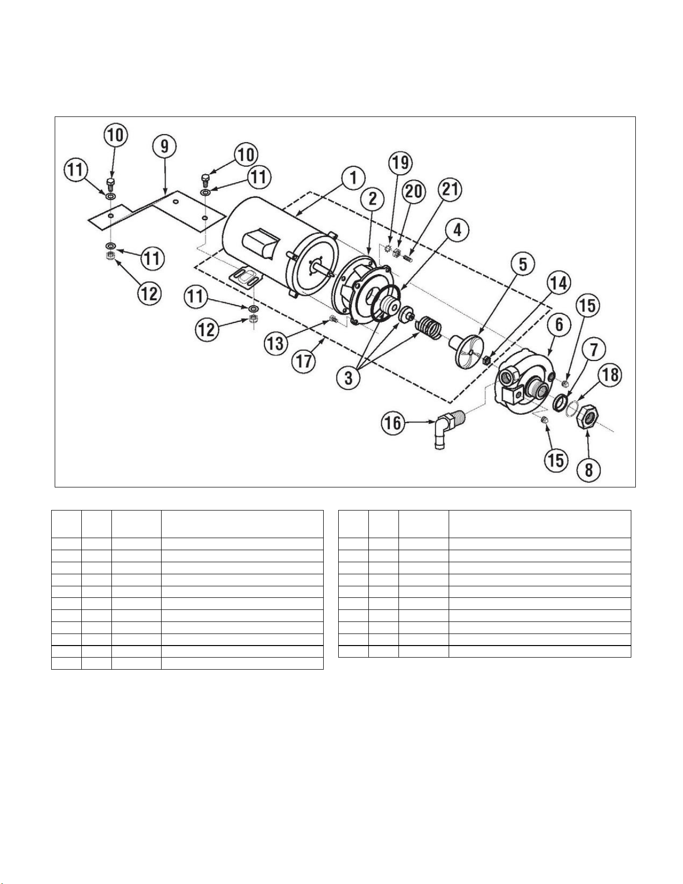
5.2.8. Wash Pump Assembly (1 Phase) ............................................................................................15
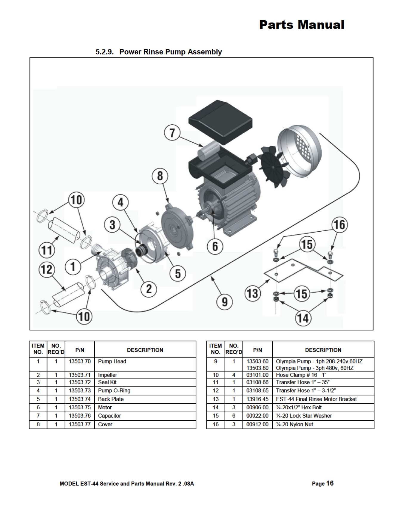
5.2.9. Power Rinse Pump Assembly .................................................................................................16
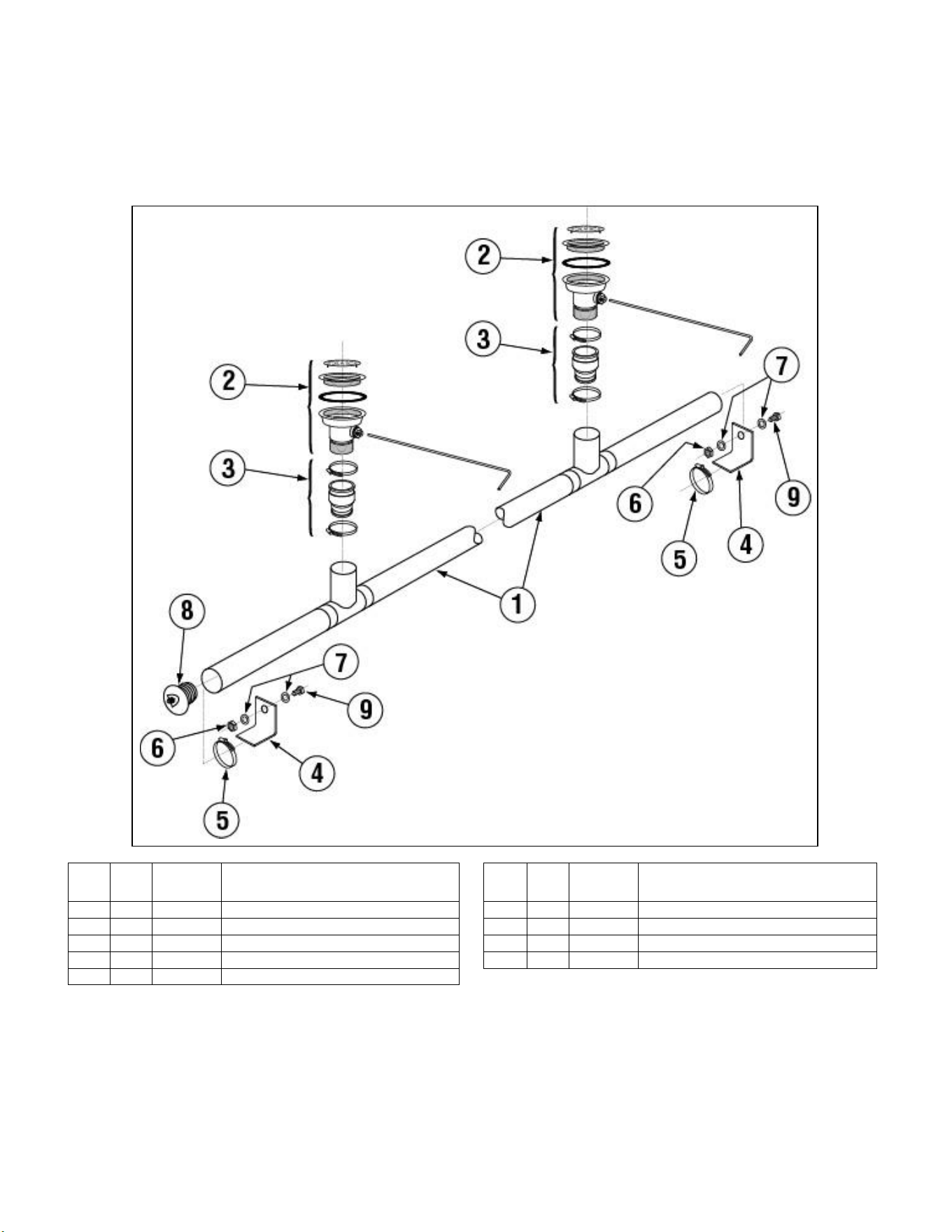
5.2.10. Drain System Assembly..........................................................................................................17
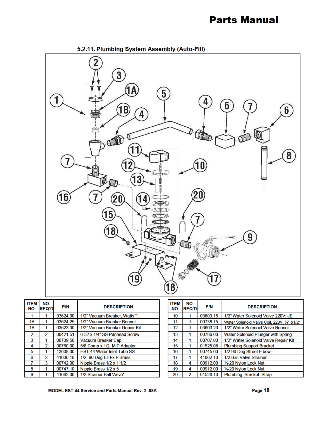
5.2.11. Plumbing System Assembly (Auto-Fill) .................................................................................18
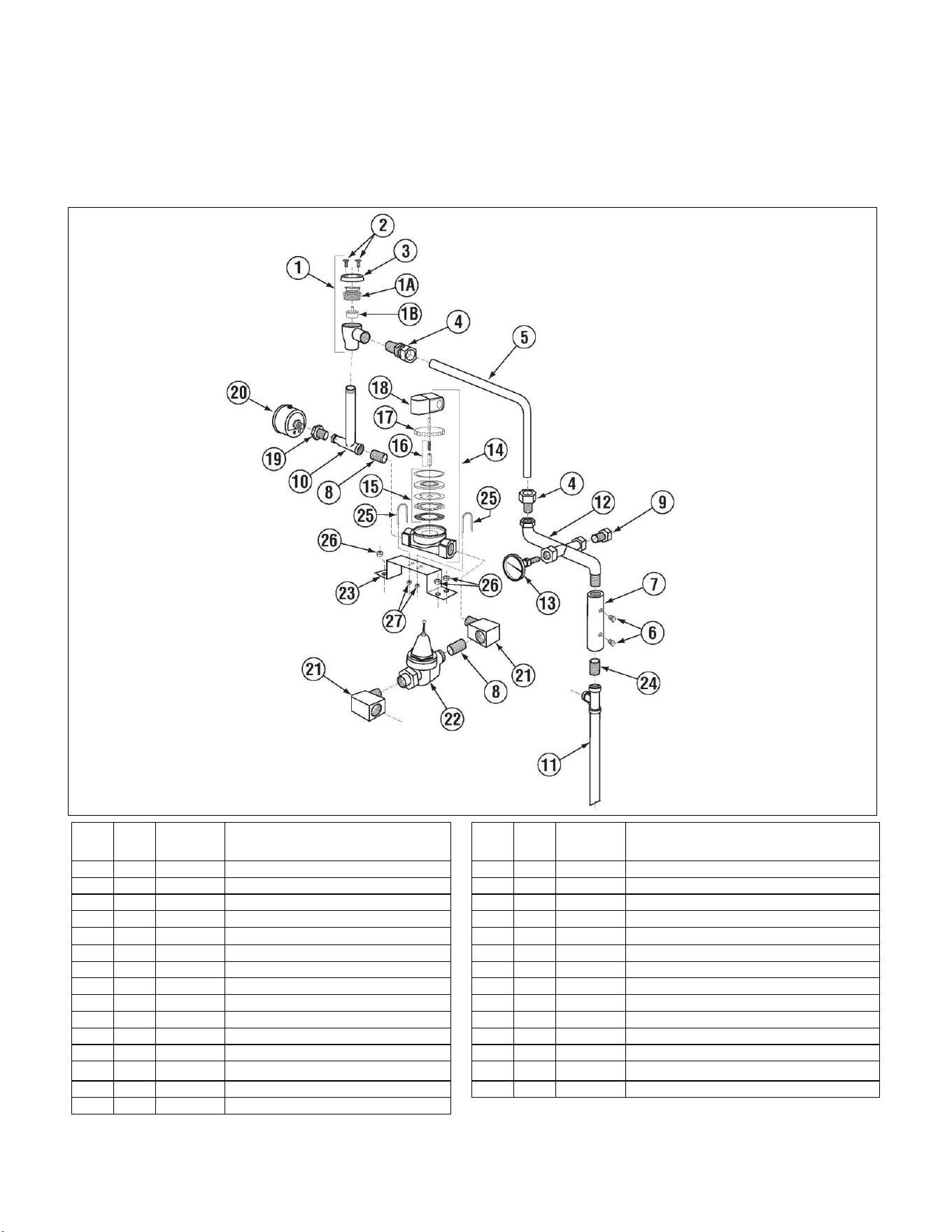
5.2.12. Plumbing System Assembly (Final Rinse) ..............................................................................19
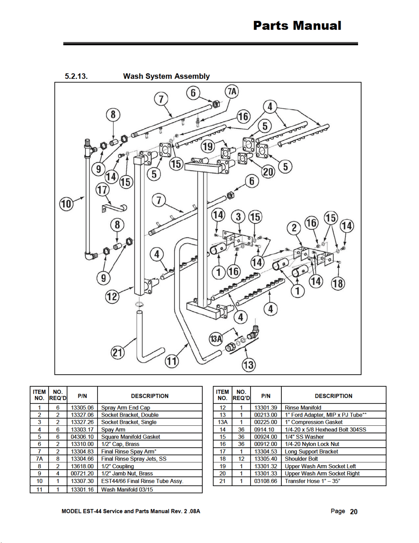
5.2.13. Wash System Assembly ..........................................................................................................20
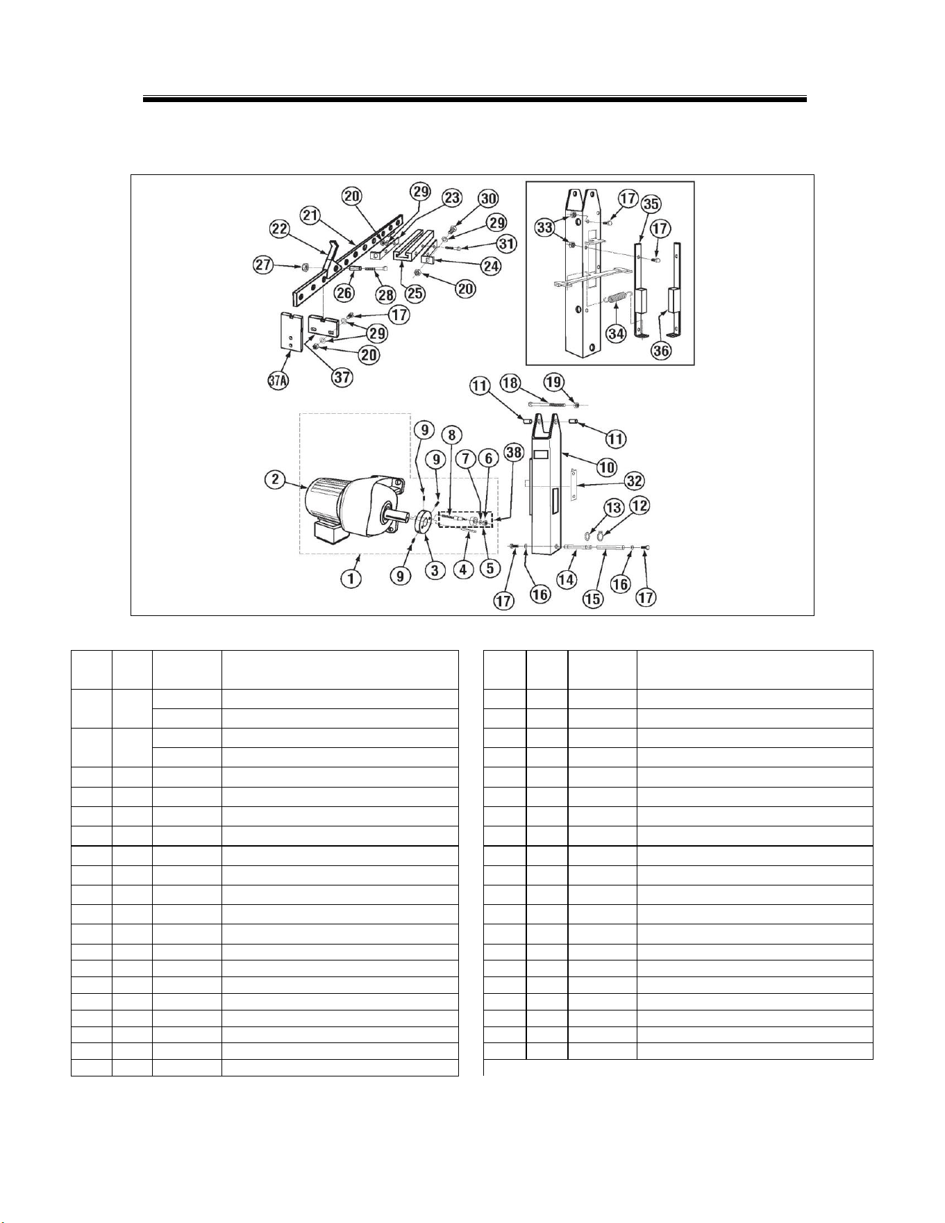
5.2.14. Rocker Arm Assembly ............................................................................................................21
5.2.15. Start Switch and Rinse Switch Assembly (Effective May 2014) .............................................22
5.2.15.1. Right-to-Left Assembly .................................................................................................22
5.2.15.2. Left-to-Right Assembly .................................................................................................23
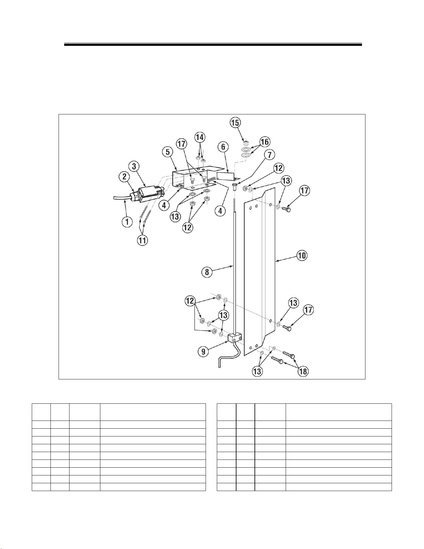
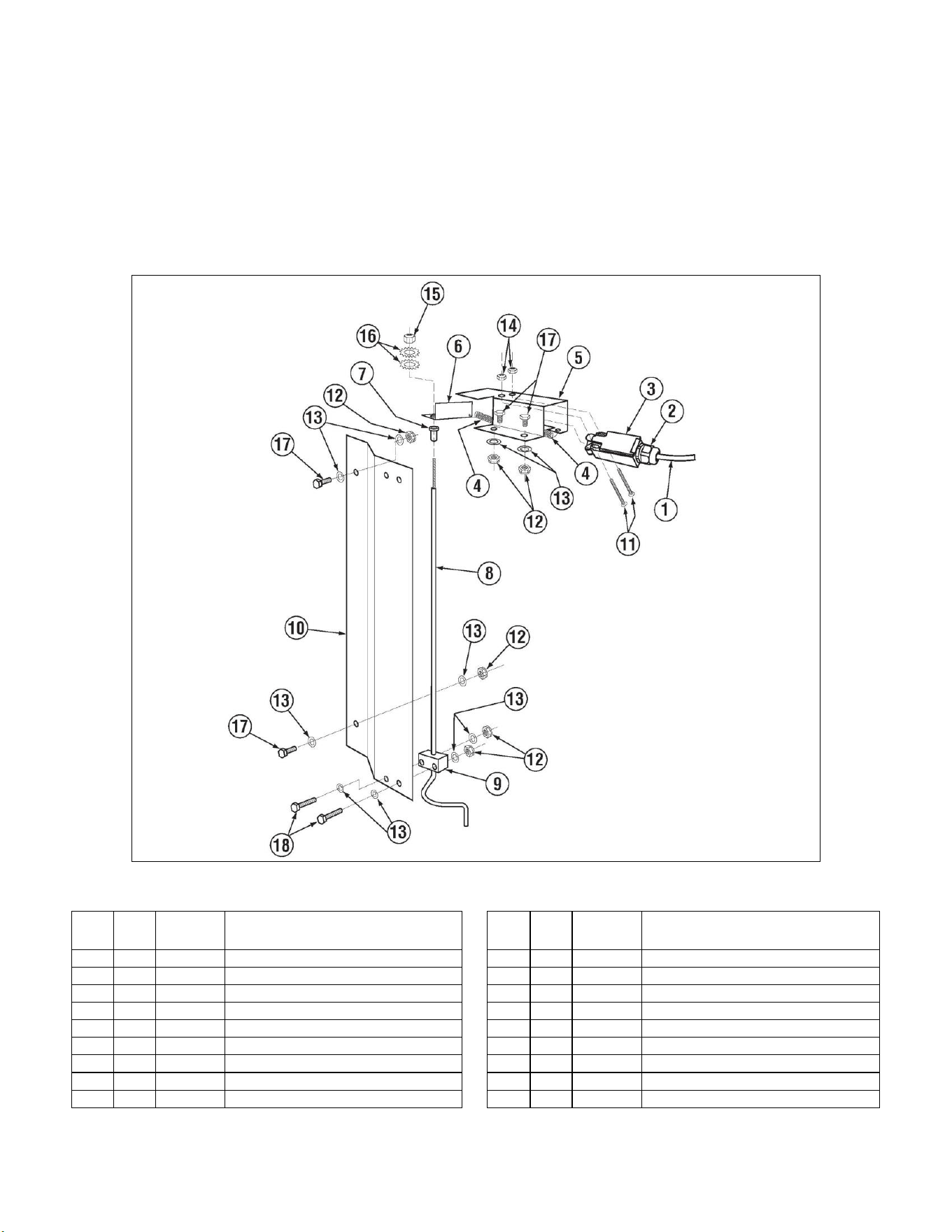
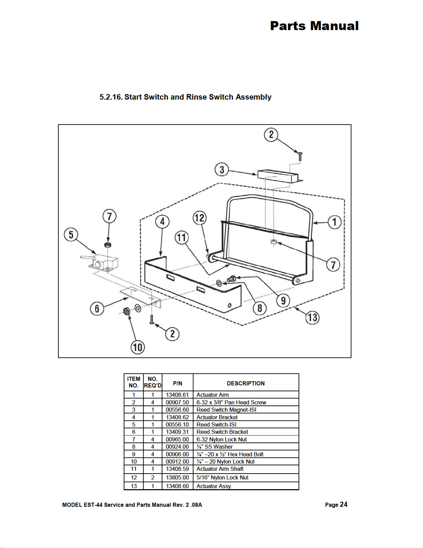
5.2.16. Start Switch and Rinse Switch Assembly ...............................................................................24
5.2.17. Door Switch Assembly (Effective August, 2014) ....................................................................25
5.2.18. Optional E-Temp Heater (Effective September 1, 2018) .......................................................26
5.2.19. Optional E-Temp Heater .......................................................................................................27
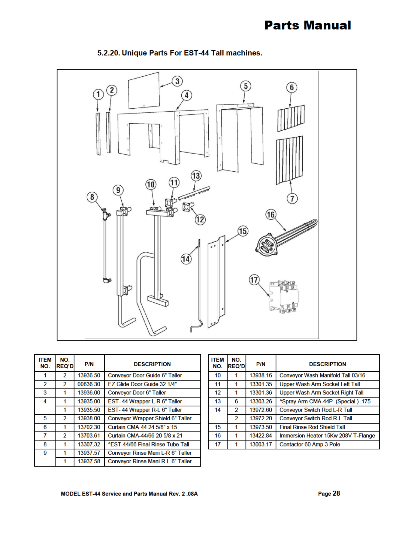
5.2.20. Unique Parts For EST-44 Tall machines...............................................................................28
6. TABLE LIMIT SWITCH (P/N 13469.20) .......................................................... 29
7. DRAIN WATER TEMPERING KIT (OPTIONAL) ............................... 30 & 31
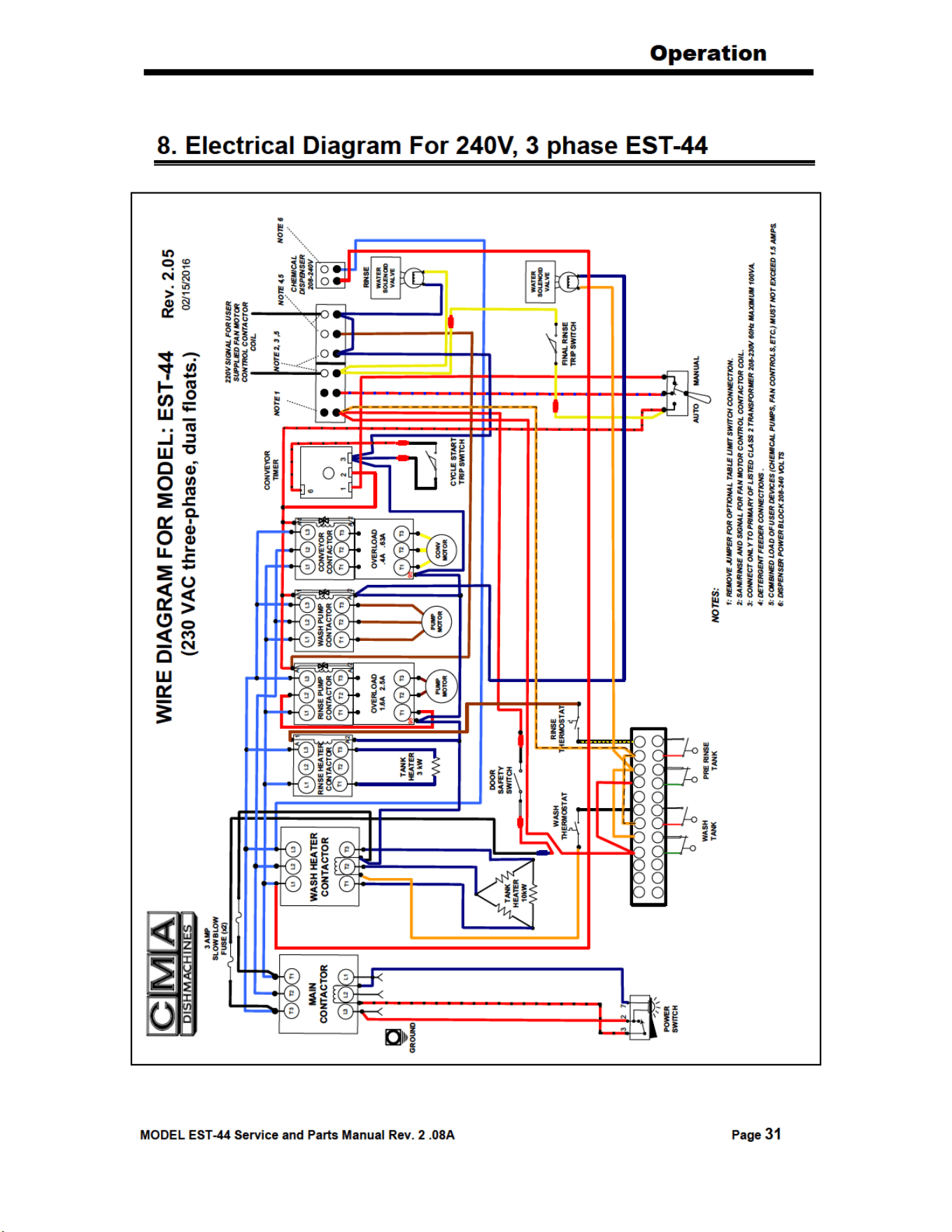
8. ELECTRICAL DIAGRAM FOR 240V, 3 PHASE EST-44 .............................. 32
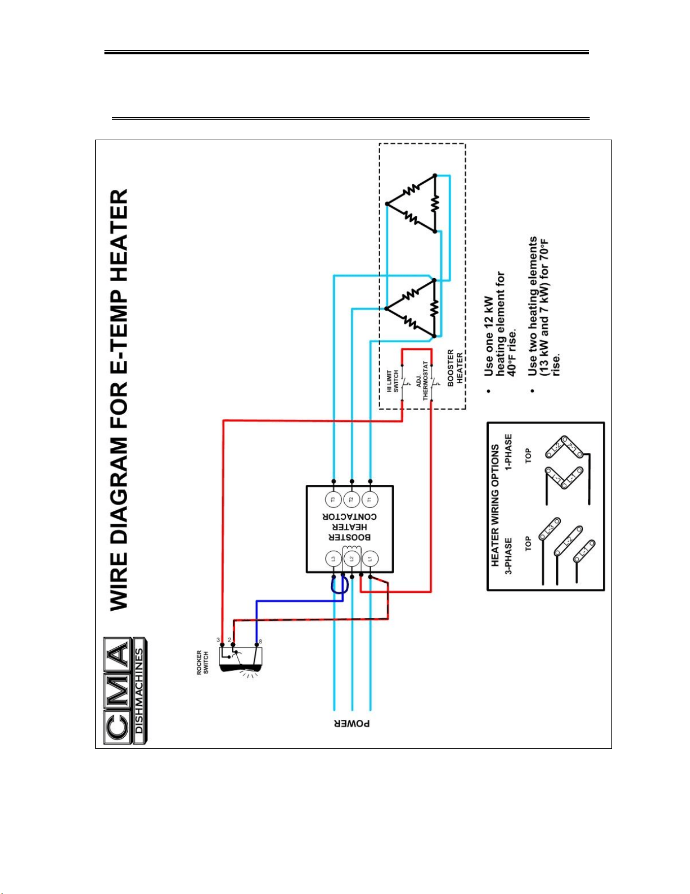
9. ELECTRICAL DIAGRAM FOR E-TEMP HEATER ONLY .......................... 33
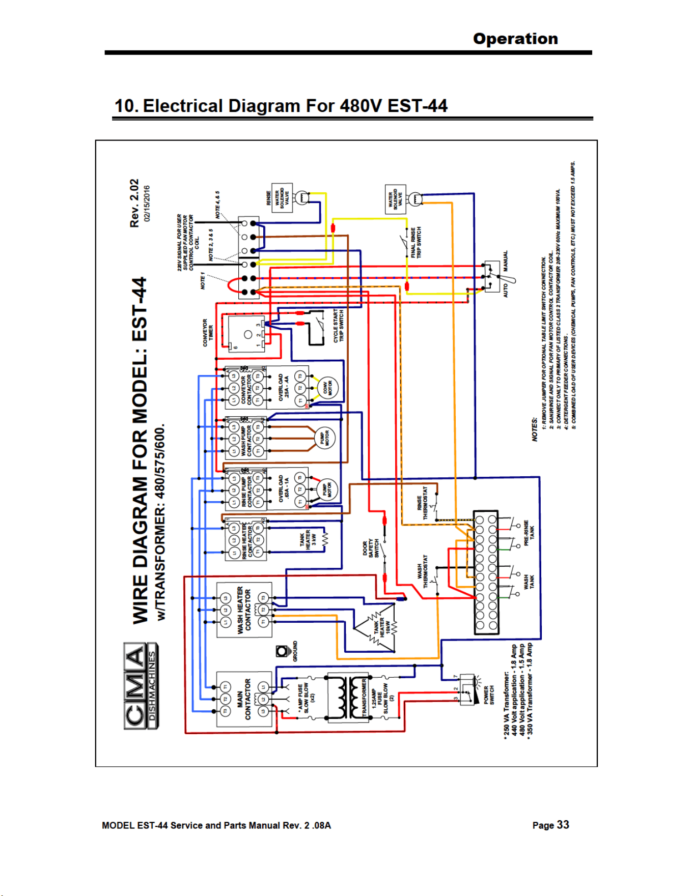
10. ELECTRICAL DIAGRAM FOR 480V EST-44 ................................................. 34
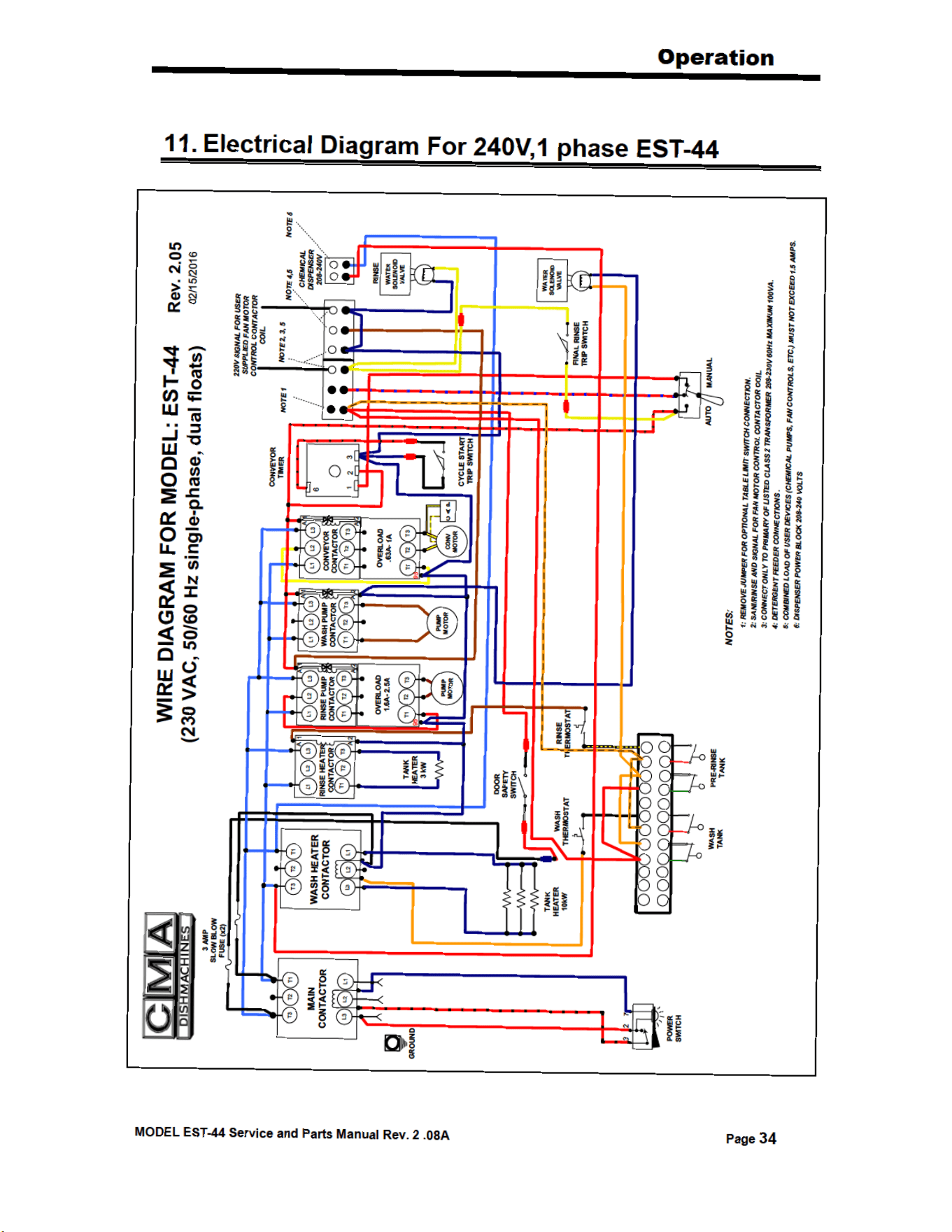
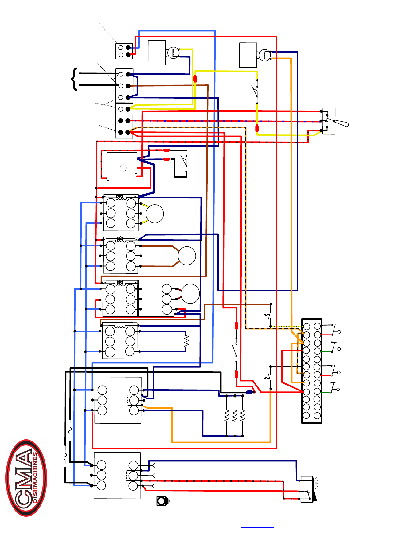
11. ELECTRICAL DIAGRAM FOR 240V,1 PHASE EST-44 ...................... 34 & 35

MODEL EST-44 Service and Parts Manual Rev. 2 .08A Page
2
1. Specifications
1.1. EST- 44
WATER CONSUMPTION
PER RACK (FINAL RINSE)
.46 GAL.
.46 GAL.
PER HOUR (FINAL RINSE)
114 GAL.
114 GAL.
CONVEYOR SPEED
FEET PER MINUTE
6.75
6.75
OPERATING CAPACITY
RACKS PER HOUR (NSF rated)
249
249
OPERATING TEMPERATURE
WASH RECOMMENDED
140° - 150° F
150° - 160° F
PUMPED RINSE RECOMMENDED
140° - 150° F
150° - 160° F
FINAL RINSE RECOMMENDED
140° - 150° F
180° - 195° F
WATER REQUIREMENTS
INLET TEMPERATURE (MIN)
140° F
180° F
WATER INLET SIZE
1/2”
FINAL RINSE SIZE
1/2”
DRAIN SIZE
2”
FINAL RINSE PRESSURE
20 PSI
HEATERS
WASH HEATER
13.3 KW/240V(1 phase)
13KW/208V(3 phase)
RINSE HEATER
3KW/240V, 2.25KW/208V
MOTORS
WASH PUMP
1 HP
RINSE PUMP
1/3 HP
CONVEYOR
1/8 HP
DIMENSIONS
DEPTH
25-1/8”
WIDTH
44”
HEIGHT
55 -1/2”-56-1/2”
STANDARD TABLE HEIGHT
32 ½” adjusts to 34”
MAX CLEARANCE FOR DISHES
VENTILATION REQUIREMENTS CFM
19”
600 Total, 400 clean side, 200 soil side
STANDARD RACKS
VOLTS
PHASE
AMPS
AMPS(Tall)
ELECTRICAL RATING 208
1
71
N/A
240
1
80
N/A
208
3
55
60.5
240
3
62.5
69
480
3
24
27
SHIPPING WEIGHT
662#
(300kg)
High temp
Low Temp

Getting Started
2. Getting Started
2.1. Introduction to CMA Model EST-44
The EST is designed to give maximum cleaning in 44 inches. It represents the cleaning power
of machines twice its length. The curtains incorporated in the dishwasher minimize the transfer
of water from tank to tank during the wash and sanitizing procedures.
The energy costs for running the new EST -44 have been greatly reduced, by the introduction of
our new Stage Washing Process. The EST-44 Conveyor dishwasher lowers gallon/rack
ratings and is directly related to CMA's new Power-Rinse Stage that has been introduced.
The EST-44 new Re-circulating Wash and new Power-Rinse Stage greatly reduce the
amount of chemicals being used, thus adding a significant cost reduction and energy
efficiency to its' operation.
The EST -44 can be used as a high or low temperature dishwasher, with the new wash tank and
power rinse tank designs, both having their own re-circulating pumps. The Power Rinse Stage
provides a fresh cleansing rinse, before the dish rack advances into the Power Rinse and sh
Water and Sanitizing Rinse Stages.
The initial-fill water and the final rinse water that is supplied to the EST -44 must be a minimum of
140
°
F, in low-temperature applications, while high-temperature machines will require two water
lines; one at a minimum water temperature of 140
°
F to fill the dishwasher, and the second with a
minimum of 180
°
F for the final rinse. With the introduction of the new optional E-Temp Booster
Heater, it will be oered fully integrated to the dishwasher.
The EST -44 also features a stainless steel scrap accumulator tank and tray, which must be
emptied on a periodic basis, as necessary. The EST machine is designed to deliver 0.49 gallons
of fresh rinse water for each rack. This water flows from the rinse and power-rinse tanks into the
wash tank, and then overflows into the scrap tray, carrying any debris that may have fallen into
the wash tank, thereby providing a much cleaner environment for the washed and rinsed dishes.
If preferred, there are also options such as a Corner Feed System, optional Vent Hood Adapters,
Exhaust Fan Control Circuits and a Drain Tempering Kit. CMA also oers a full line of other
machine accessories, including stainless steel dishtables. (See equipment catalog)
DISCLAIMERS
CMA expressly disclaims any and all warranties, express or implied, relating to the installation of any and all CMA equipment that
is installed by chemical dealers, contracted servicers or third party servicers to CMA equipment. If the installation instructions
are not followed exactly (to the leer), or, any person or company conducting e installation of the CMA equipment, revise e
insllation procedures or alter the insuctions in any manner, the CMA warranty becomes void. If, due to the improper
installation of CMA equipment, this equipment ceases to operate properly or aects other pa of the CMA dishwashing
equipment, in that the other par become defective, the CMA warranty becomes void. CMA will not be liable or responsible or
warrant CMA equipment, due to improper installation of any CMA model dishwasher.
CMA does NOT endorse "Tankless On-Demand" water heaters for use on CMA Dishmachine products. On most applications, the
volume of hot water required for commercial dishmachines exceeds the capacity of these types of heating sources. You will nd
that most, if not all, commercial dishmachines have been programmed with auto-lling features that require quick filling, with a
designated limited time.
CMA endorse, and highly recommends, the standard "tank" style water heaters, sized prorty to handle each paicular
facility with their water heating requirements. A "tank" style water heater stores and supplies a large capacity of preheated water
before providing hot water to the dishmachine. To meet required health codes, there must be a reliable and consistent ow of
adequate hot water supplied to the dishmachine. If the facilities' ''tank" style water heater is marginal in size, CMA recommends
installing a proper size Hatco Booster Heater, a CMA's E-Temp 40 or 70-degree-rise Booster Heater (that can be installed on CMA
Conveyors), or a CMA Temp-Sure Booster Heater (for door and undercounter dishmachines). All are designed to adequately
achieve results.
Impoant: Make sure incoming power supply corresponds to the voltage listed on the data plate. If the voltage is too low (206V or
less), the heating elements will not reach desired temperature specied by manufacturer, and performance will compromised.
The heating element needs to be sized according to the facilities available volge, which must noted on your purchase order
to CMA for a special dishmachine. Special lower voltage higher kilowa heaters are available upon request.
Make sure a fused disconnect switch or circuit breaker (not supplied) is installed in the electrical service lines supplying this
dishwasher and should meet the requirements of your local electrical code.
MODEL EST Service and Pas Manual Rev. 2 .08A
Page 3

Getting Started
MODEL EST-44 Service and Parts Manual Rev. 2 .08A Page
9
2.2.4. Scrap Tray Assembly Installation
The Scrap Tray Assembly and Overflow Chute, which were shipped inside the machine, can
easily be installed by executing the following steps: Figure 2.2.4 below illustrates the assembly,
as it would appear for a Left-to-Right machine – (a Right-to-Left machine would simply be the
mirror image).
Caution:
1. For proper spacing, the SS flat washer must not be located between the head of the truss
head bolt and the inside of the machine.
2. The Illustration below shows the correct placements of the scrap trap holder. Do not
install upside down, otherwise water deflection takes place.
Figure 2.2.4
1. Remove items from their packaging and verify that all “installation hardware” was included.
2. Secure the scrap trap holder to the dishmachine by using the four ¼-20 X ½” Hex Head
Bolts, the ¼” SS Flat Washers, and the ¼”-20 Nylon Lock Nuts that were provided.
3. Set the scrap trap body—with the scrap trap drawer inserted—into position on the scrap trap
holder. (Attach the drain as specified in Section 2.2.3)
Getting Started
MODEL EST-44 Service and Parts Manual Rev. 2 .08A Page
11
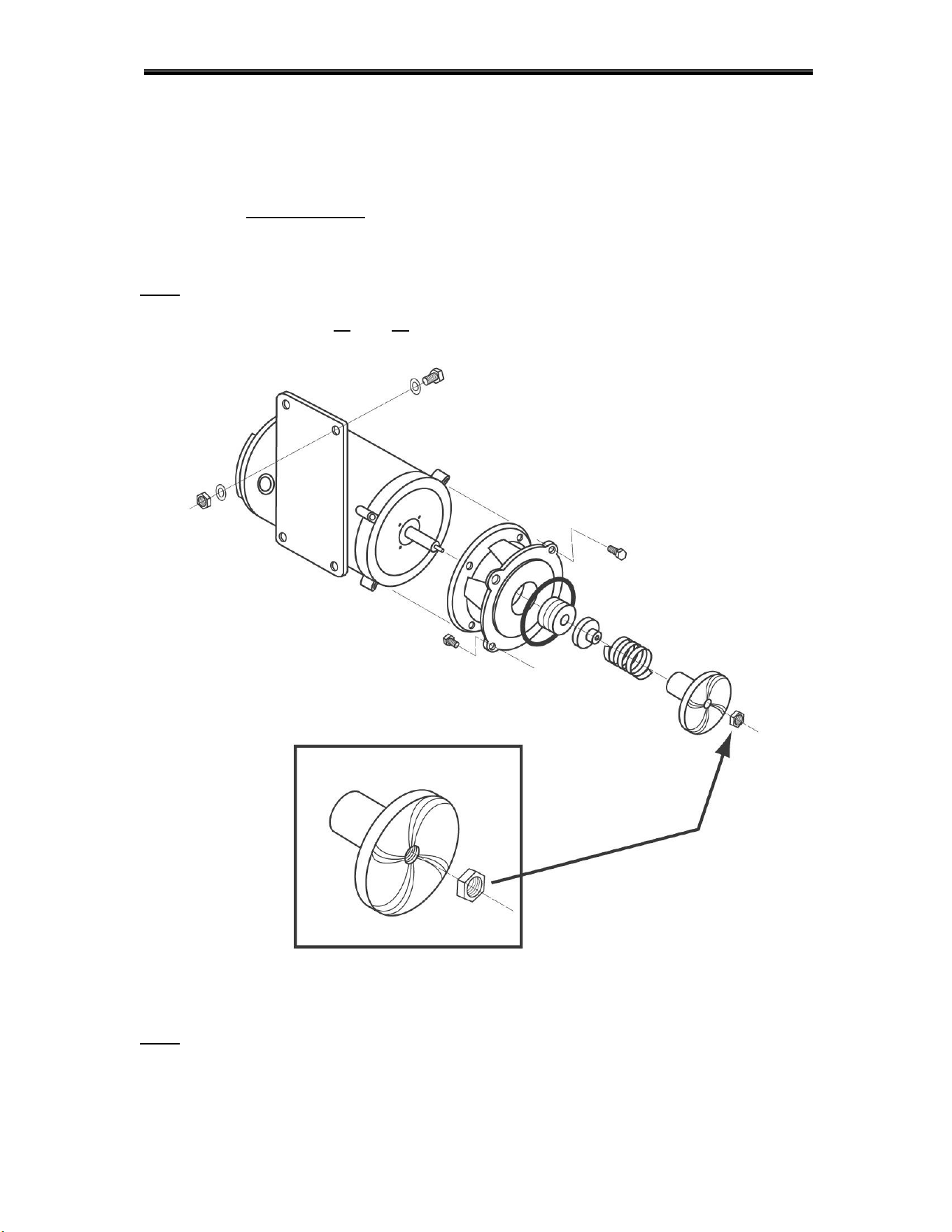
2.2.6. Wash Pump Assembly and Impeller
The standard wash pump motor is three-phase and can operate clockwise, as well as counter-
clockwise; the Nylon Lock Nut used to hold the impeller in place (See Figure 2.2.6), is very
important. When servicing the Wash Pump Assembly and replacing the seals, make sure it is
secured properly; otherwise, if the motor turns the wrong direction, the impeller may spin-off the
motor shaft causing damage to the impeller.
Note: ALWAYS CHECK THAT THE DIRECTION OF THE MOTOR ROTATION IS CLOCKWISE,
WHEN REINSTALLING THE WASH PUMP. IF THE MOTOR IS TURNING COUNTER-
CLOCKWISE, EXCHANGE L1 AND L3 WIRES ON MAIN CONTACTOR
Figure 2.2.6
Note: The Nylon Lock Nut indicated by the arrow in Figure 2.2.6 must be removed before
attempting to remove the water pump impeller.
Getting Started
MODEL EST-44 Service and Parts Manual Rev. 2 .08A Page
12
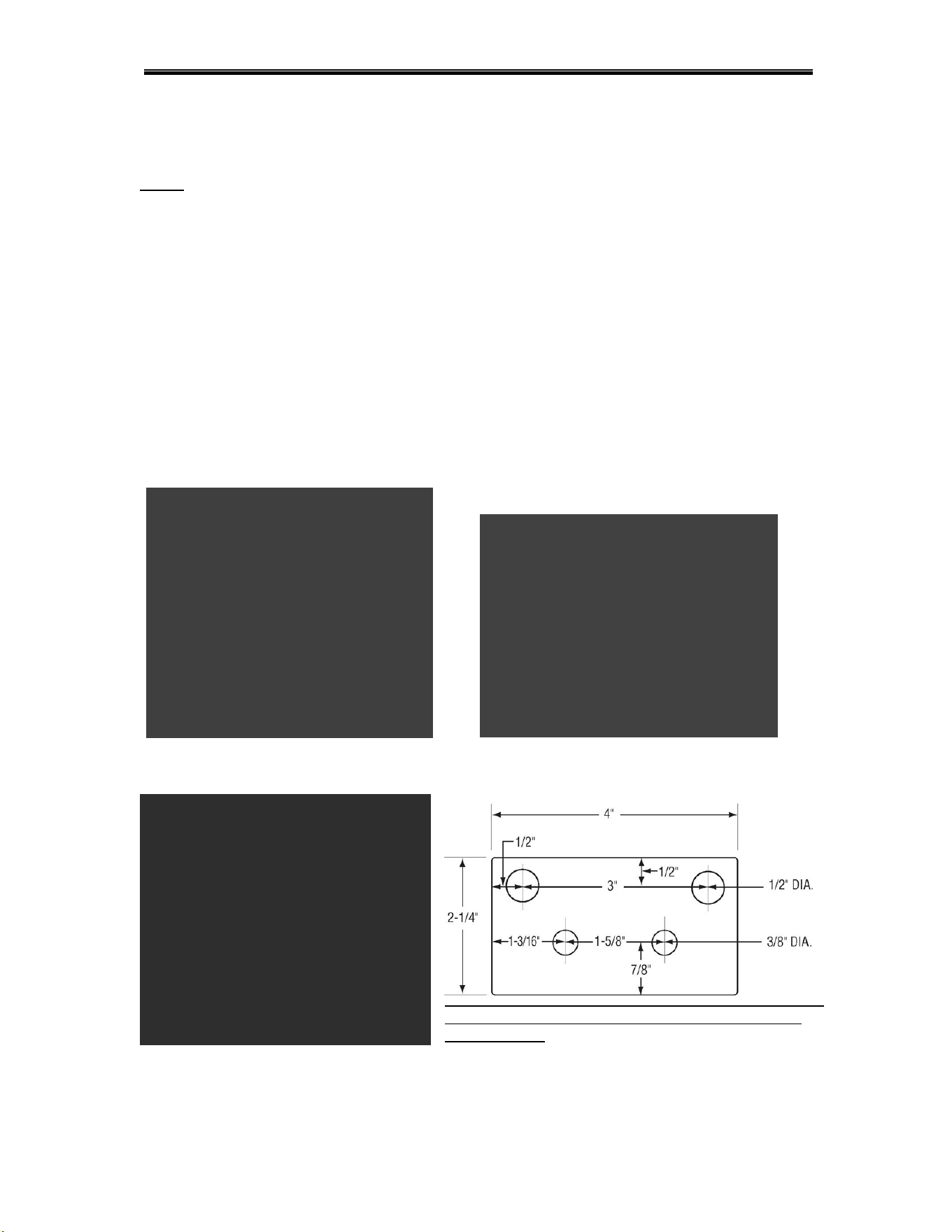
2.2.7. Table Limit Switch Installation
The Model EST-44 is shipped with a Table Limit Switch fully wired and connected in the main
control box, ready to be installed on the clean side of the dishtable. The Table Limit Switch
MUST be installed to prevent dishrack and Conveyor Drive damage.
1. Remove the template that was shipped to hold the table-limit switch assembly
together.
2. Remove the activator bar (Figure 2.2.7a).
3. Position the template in the middle of the clean side of the dishtable.
4. Mark the end of the table, where the holes need to be drilled (Figure 2.2.7b).
5. Drill the holes.
6. Attach the Table Limit Switch, using the hardware supplied.
7. Reattach the activator bar removed earlier.
8. Test that it functions properly (Figure 2.2.7c).
Figure 2.2.7a Figure 2.2.7b
Note: This terminal is not actual size ,not to be used
for installation!
Figure 2.2.7c
Getting Started
MODEL EST-44 Service and Parts Manual Rev. 2 .08A Page
15
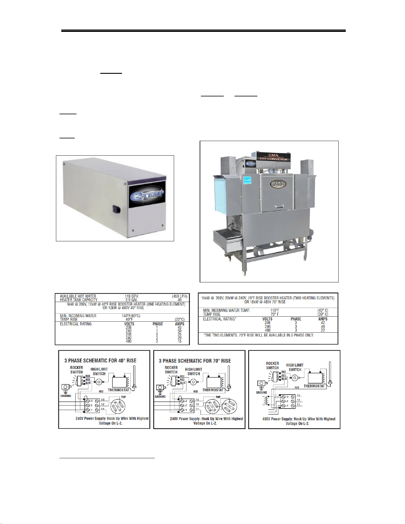
2.2.11. (Optional) E-Temp Booster Heater
*
The Optional E-Temp Booster Heater can only be ordered with a dishwasher, already installed at
the factory; it cannot be installed in the field. The E-Temp Booster heater will be fully integrated
into the EST-44 conveyors’ plumbing system. It will require its’ own power supply of 208 volts to
240 volts, in single-phase or three-phase. The unit can be specially ordered as a 480-volt unit, in
three-phase only; temperature is available in a 40° rise or 70° rise. The E-Temp Booster heater
contactor is located in the EST-44 Main Control Box (See item 7, page 6).
Note: E-Temp heater is shipped on the machine empty to prevent freezing. When machine
is powered up for the first time, the booster heater must be filled by pressing and holding
rinse switch to prevent heater damage.
Note: 70° degree rise E-temp Booster Heater is only available in Three-Phase.
*
Electrical and plumbing connections must be made by a qualified person who will comply with all
available Federal, State, and Local Health, Electrical, Plumbing and Safety codes

Getting Started
MODEL EST-44 Service and Parts Manual Rev. 2 .08A Page
16
2.3. EST-44 Safety Tips
DANGER:
Always turn off the main circuit breaker at the wall when
installing or servicing this dishmachine and/or an E-Temp
Booster Heater. Even with the machine’s power switch “off”,
there is a live connection being carried to the switch from the
dishmachine contactor.
CAUTION:
Do not get in the path of the Conveyor Rocker Arm or the
conveyor’s moving bar. Do not reach into the rocker arm area
without first making sure the dishmachine is turned “off” at the
circuit breaker.
CAUTION:
Do not open the front door when the machine is in operation.
CAUTION:
Avoid spraying water on or around the electrical control box
located on the top of the machine. When cleaning, do not
spray water directly on the motors.
CAUTION:
When removing the Final Rinse Arms for cleaning, exercise
caution. The Final Rinse Arms may be filled with chemicals or
have additional pressure applied.
Operation
MODEL EST-44 Service and Parts Manual Rev. 2 .08A Page
19
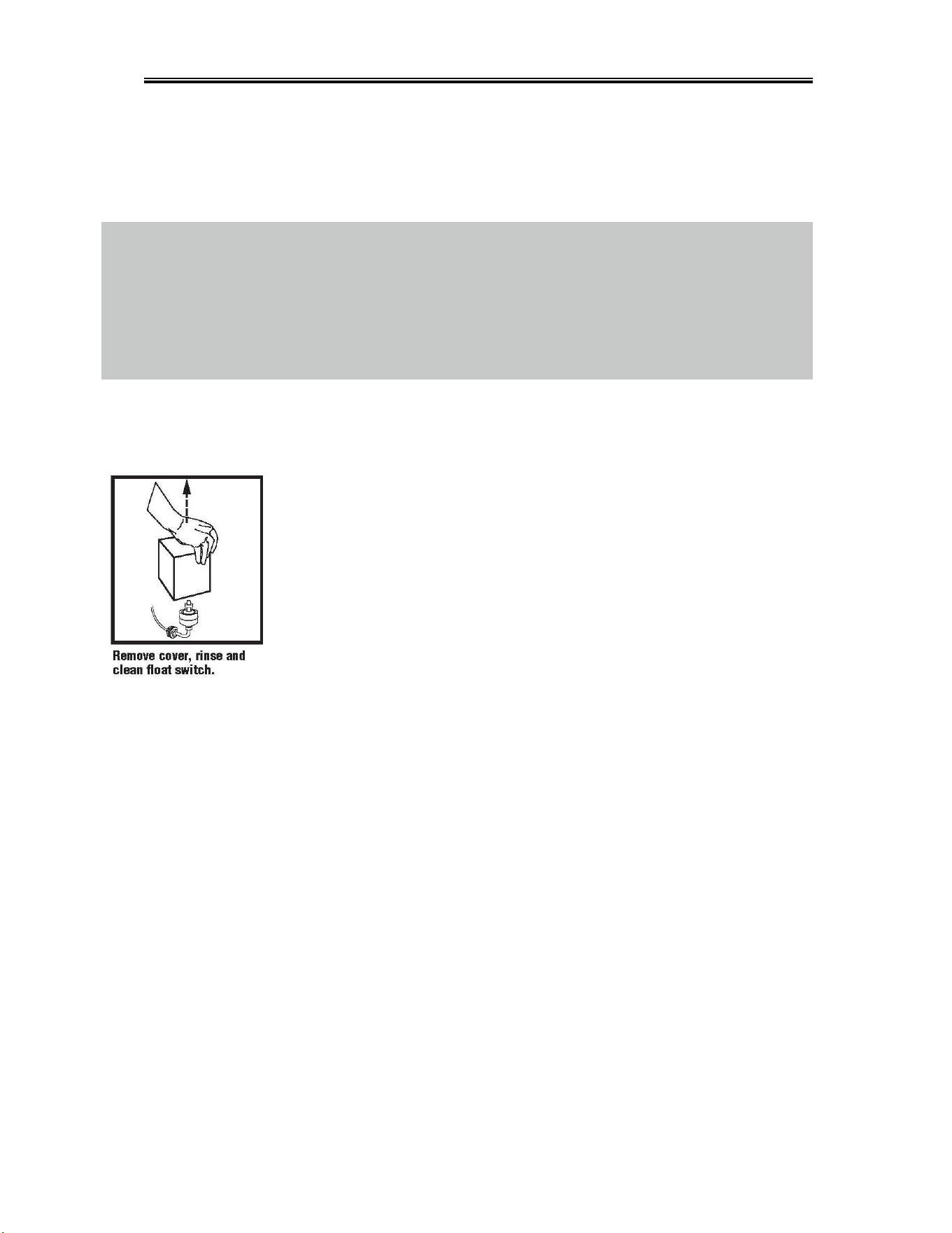
3.2. Cleaning Instructions
See Fig.3.1, Items 2,6 See Fig.3.1, Items 4 See Fig.3.1, Items 5 See Fig.3.1, Items 3

Operation
MODEL EST-44 Service and Parts Manual Rev. 2 .08A Page
20
3.3. Regular Service and Maintenance Checklist
Check all electrical connections, assuring they are tight and secure.
Check all Water, Drain, and Plumbing connections for leaks; tighten if needed.
Check Final Rinse Arms: the Rinse Jet Spray should be straight up & down.
Check Wash Pump motor rotation, making sure it is turning clockwise.
Check Dish rack Movement, Conveyor Arm & Bar, and Conveyor Dog Alignment.
Check Tray Track Guide and Rail & Table Alignment throughout dishwasher.
Check Timer Dipswitch Setting; only switch 6 should be in “on” position (32 seconds)
Check Wash-Tank Temperature 150° F Minimum.
Check Power-Rinse Tank Temperature 160° F Minimum.
Check Final-Rinse Temperature 180° to 195° F (High-Temp)
(140° F for Low Temp)
Check Final Rinse Pressure 20 psi, ±5 psi
Check Table-Limit Switch operation (If not installed, Warranty will be voided)
Check Vent Hood adapter baffle position to draw steam. (Optional)
(Keep baffles open to a minimum)
Check and make sure the dishwasher is level.
Check to make sure all curtains are in place.
Read all labeling and follow procedures.
Review installation section before beginning the installation of the Model EST-44
Conveyor Dishwasher. All installation procedures and guidelines MUST BE followed
precisely.
Operation
MODEL EST-44 Service and Parts Manual Rev. 2 .08A Page
21
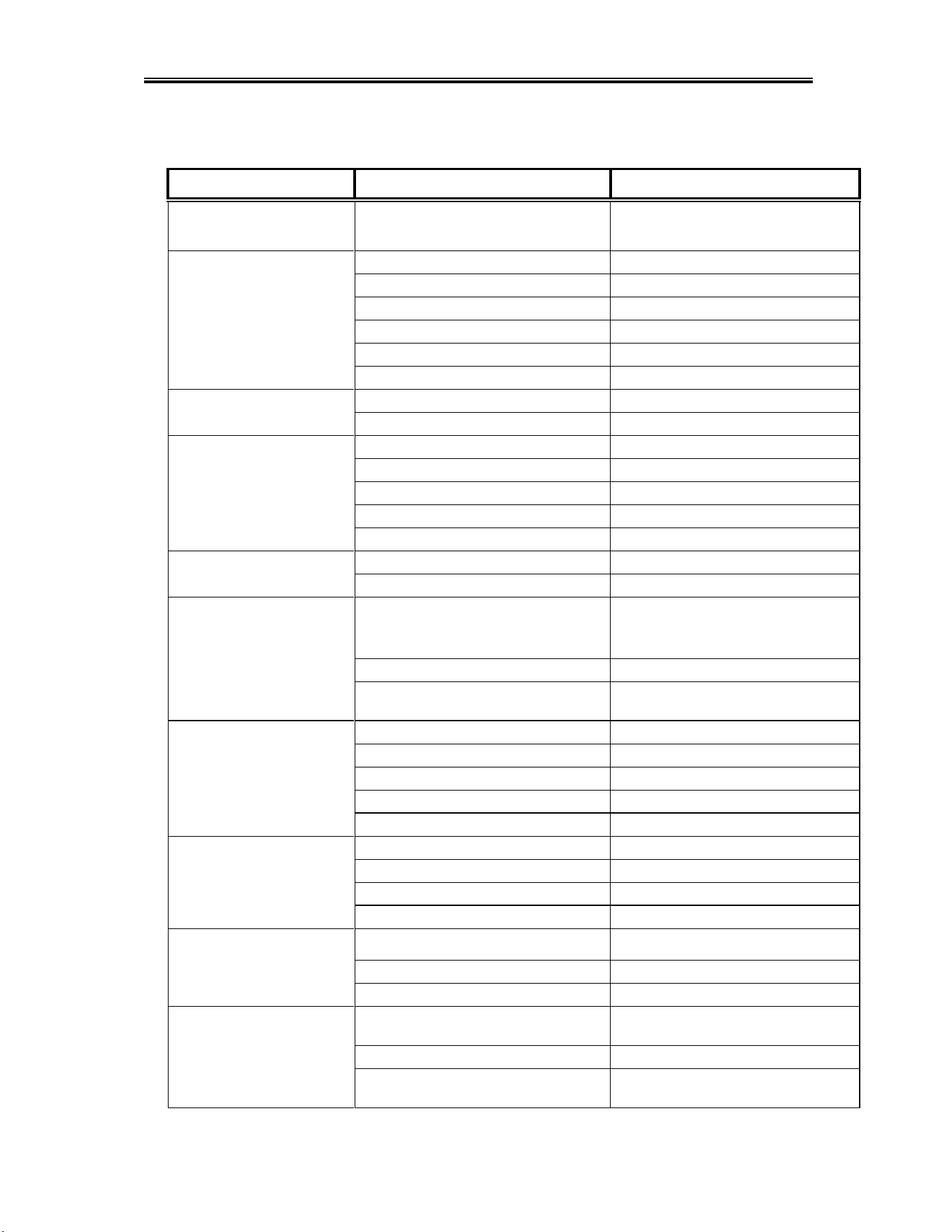
3.4. Trouble Shooting
PROBLEM
LIKELY CAUSE
SOLUTION
Wash or power rinse
motor not running
Bad motor or capacitor
Faulty contactor
Replace defective motor or
Replace contactor
Machine inoperative
Fuse is burned out
Replace fuse
Table limit switch
Remove dish rack at switch
Defective door reed switch
Replace reed switch
Defective start reed switch
Replace reed switch
Defective auto/manual switch
Replace switch
Defective Conveyor Timer
Replace timer
Machine runs continuously
Timer or settings@ 60 Sec
Replace timer or change settings
Contactor stuck
Replace contactor
Heater (no heat)
Float switch
Check movement-replace it
Defective thermostat or setting
Replace thermostat or adjust
Defective heater contactor
Replace heater contactor
Defective heater
Replace heater
Wire connections
Check and correct
Racks stuck
Old or broken rack
Replace rack
Tray track alignment
Adjust track to table properly
Wash & Power rinse tank
temperature low
Incoming water supply
(Low temp 120°F-Recommende140°F;
High temp 180°F minimum)
Check hot water supply
Thermostat setting
Adjust thermostat to mach NSF label
Vent hoods baffle setting
Set CMA Vent hood adapter baffles as
instructed on page 13
Low final rinse pressure or
no rinse pressure
Plugged rinse jets
Remove and clean
Pressure regulator out of adjustment
Adjust pressure regulator20psi to 23psi
Water sol. valve coil or diaphragm
Replace or clean
Dirty rinse jets
Remove and clean jets
Defective rinse reed switch
Replace reed switch
Machine using too much
chemical
Quick drain on wash end
Plumb quick drain back into wash tank
Dispenser or settings
Check dispenser troubleshooting guide
Rinse pressure
Set 20 psi.
Soil
Check scrap basket sand float function
Machine loosing water
Quick drain on dirty side table
Check quick drain connections
Sheet pans
Use CMA sheet pan rack
Drain valves open
Close completely
Low wash arm pressure
Debris In wash & power rinse arm
manifolds
Remove arm, check & clean debris from
manifolds
Clogged jets
Clean jets
Motors connected wrong
Connect motors to reverse impeller
direction

Operation
MODEL EST-44 Service and Parts Manual Rev. 2 .08A Page
4
TIPS TO SAVE A SERVICE CHARGE
If the Lessee of this equipment initiates a service call and it is subsequently determined that the
problem does not relate to part failure or out of chemicals, there will be a minimum service charge
for a service person to respond.
It is recommended that you check the following items before initiating a service call:
Circuit breaker position. Should be “ON”.
Clogged drains (at any point in drain line).
Lack of soft water (check salt level in brine tank).
Lack of hot water due to valves shut off or incorrect thermostat settings.
Failure of equipment unrelated to the machine.
Abuse to equipment or failure to perform minimum cleaning requirements as outlined at
time of installation.
a. Rinse and wash arm tips clean and free of debris.
b. Strainer trays clean and free of debris.
c. Water tank drains clean and free of debris.
Trip switch blocked or held from free movement due to a lodged utensil or dish.
Lines to chemical buckets found in wrong containers or empty. (Lines to the buckets are
color-coded.)
Lessee’s service responsibility shall be limited to its initial orientation, delivery of chemicals,
adjustment of chemical injection system, and replacement of parts found to be worn or defective.
Parts Manual
MODEL EST-44 Service and Parts Manual Rev. 2 .08A Page
7
5.2.2. Control Box Assembly (3 Phase)
ITEM
NO.
NO.
REQ’D
P/N
DESCRIPTION
ITEM
NO.
NO.
REQ’D
P/N
DESCRIPTION
1
1
00449.50
Lock, Keyless
14
1
00470.10
Toggle Switch Rubber Boot
2
2
13403.26
Fuse, 3-Amp/250V Slow Blow
15
1
13003.70
Toggle Switch SPDT 20AMP
3
1
13941.12
EST-44 Control Box Body
16
1
00454.20
8-Pole Terminal Block
4
4
00909.00
¼-20x3 ¼ SS Hexhead Bolt
17
1
15520.00
Power Block 12-Position
5
8
00924.00
¼ SS Washer
18
1
00421.83
Power Rocker Switch, Red
6
4
13941.20
EST-44 Control Box Legs
19
1
13003.60
Starter DIN Rail
7
2
13003.17
Contactor 60 Amp 3 Pole
20
1
13941.22
EST-44 Control box lid
8
1
13013.45
Overload Relay 0.4 to 0.63 Conveyor
21
4
00912.00
¼-20 Nylon Lock Nut
9
4
13012.26
Motor Contactor, 220V
22
2
13003.62
Din Rail Mounting Bracket
10
1
13426.50
Ground Block
23
1
13418.60
Dip Switch Timer 230 V
11
2
03202.08
Thermometer Bracket
24
3
13012.29
Surge Absorber
12
2
03202.00
Thermometer
25
1
06232.20
EST Conveyor Label Full Size label
13
1
13014.40
Overload Relay 1.6 to 2.5 Power Rinse
Parts Manual
MODEL EST-44 Service and Parts Manual Rev. 2 .08A Page
8
5.2.1. Control Box Assembly (1 Phase)
ITEM
NO.
NO.
REQ’D
P/N
DESCRIPTION
ITEM
NO.
NO.
REQ’D
P/N
DESCRIPTION
1
1
00449.50
Lock, Keyless
14
1
13014.40
Overload Relay 1.6 to 2.5 Power Rinse
2
2
13403.26
Fuse, 3-Amp/250V Slow Blow
15
1
00470.10
Toggle Switch Rubber Boot
3
1
13941.12
EST-44 Control Box Body
16
1
13003.70
Toggle Switch SPDT 20AMP
4
4
00909.00
¼-20x3 ¼ SS Hexhead Bolt
17
1
00454.20
8-Pole Terminal Block
5
8
00924.00
¼ SS Washer
18
1
15520.00
Power Block 12-Position
6
4
13941.20
EST-44 Control Box Legs
19
1
00421.83
Power Rocker Switch, Red
7
1
13003.18
Contactor 75 Amp 3 Pole
20
1
13003.60
Starter DIN Rail
8
1
13003.17
Contactor 60 Amp 3 Pole
21
1
13941.22
EST-44 Control box lid
9
1
13014.48
Overload Relay 0.63 to 1.0 Conveyor
22
4
00912.00
¼-20 Nylon Lock Nut
10
4
13012.26
Motor Contactor, 220V
23
2
13003.62
Din Rail Mounting Bracket
11
1
13426.50
Ground Block
24
1
13418.60
Dip Switch Timer 230 V
12
2
03202.08
Thermometer Bracket
25
3
13012.29
Surge Absorber
13
2
03202.00
Thermometer
26
1
06232.20
EST Conveyor Label Full Size label
Parts Manual
MODEL EST-44 Service and Parts Manual Rev. 2 .08A Page
9
5.2.2. 480V Control Box Assembly (480V machines only)
ITEM
NO.
NO.
REQ’D
P/N
DESCRIPTION
1
1
13905.13
Transformer Box
2
1
13423.82
Transformer 480V - 240V
3
2
13403.21
Fuse Holder - Inline
4
2
13403.40
Fuse 1.25 Amp 230V Slow Blow
5
2
13402.10
Fuse 1.50 Amp 600V Slow Blow
6
1
13420.10
Fuse Clip 2-Poll, Pressure Plate
7
1
13905.23
Transformer Box Lid
8
4
00940.50
10-32 X 3/8 Truss Head Screw
Parts Manual
MODEL EST-44 Service and Parts Manual Rev. 2 .08A Page 10
5.2.3. Curtain and Optional Vent System
ITEM
NO.
NO.
REQ’D
P/N
DESCRIPTION
ITEM
NO.
NO.
REQ’D
P/N
DESCRIPTION
1
1
13912.14
CMA 44 Splash Shield (09)
6
2
13705.10
Curtain Rod Long
2
2
13702.25
Curtain CMA-44( 20-5/8” x 15”)
7
4
00914.10
1/4-20 X 5/8 Hexhead Bolt
3
2
13901.82
Hood Adapter EST-44 (2 pc set)
8
2
13901.12
CMA 44 Wash Curtain Support ('07)
4
2
13901.30
Outer Wrap Shield Curtain Support
9
4
00912.00
1/4-20 Nylon Lock Nut
5
2
13705.00
Curtain Rod Short
10
1
13702.35
Curtain CMA-44 (24 5/8" x 11-1/2”)
Parts Manual
MODEL EST-44 Service and Parts Manual Rev. 2 .08A Page 11
5.2.4. Old Wash Temperature Control System (Square Flange)
ITEM
NO.
NO.
REQ’D
P/N
DESCRIPTION
ITEM
NO.
NO.
REQ’D
P/N
DESCRIPTION
1
1
13417.75
Immersion Heater 3hp/1PH 380V 10kW
5
1
13416.10
Thermostat Bracket
1
13417.80
Immersion Heater 3Ph/1PH 240V 10kW
6
1
13417.45
Heater Gasket
2
1
13465.00
EST-44/66 Dual Float Switch
7
4
00901.00
5/16 – 18 x 1” Hexhead Bolt
3
1
13417.92
Thermostat (EGO)
8
4
13805.00
5/16 – 18 Nylon Nut
4
1
03202.00
Thermometer
9
8
00926.00
5/16” SS washer
Parts Manual
MODEL EST-44 Service and Parts Manual Rev. 2 .08A Page
14
5.2.7. Wash Pump Assembly (3 Phase)
*Includes Items 1, 2, 3, 4, 5 and 14.
ITEM
NO.
NO.
REQ’D
P/N
DESCRIPTION
ITEM
NO.
NO.
REQ’D
P/N
DESCRIPTION
1
1
00201.85
Pump Motor,1HP,60 Hz, 220/460V
12
3
00912.00
1/4-20 Nylon Lock Nut
2
1
04207.10
Pump Base Mount
13
8
00921.00
3/8-16 x 3/4” SS Hex Head Bolt
3
1
00206.30
Pump Seal Kit New
14
1
13829.00
7/16-20 Thin Nylon Lock Nut
4
1
03226.00
Pump O-Ring Gasket
15
2
00238.00
3/8” Male Plug
5
1
03222.10
Impeller (Open) SS
16
1
04604.00
^35 Deg Elbow MIP X Barb SS
6
1
04207.20
Pump Cover
17
1
00200.85
Pump Assembly, 1HP, 3Ph, 220V, 60 Hz*
7
1
00208.40
Slip Joint Nut Gasket
18
1
00208.21
Slip Joint Nut Friction Ring
8
1
00207.00
Compression Nut, 2.5”
19
2
03807.50
3/8 External Lock Star Washer
9
1
13916.40
Motor Support Bracket
20
2
03810.00
3/8-16 Thin Nut
10
3
00906.00
1/4-20 x 1/2” Hex Bolt
21
2
00975.00
3/8”-16 x 1 ½” SS Stud
11
6
00922.00
1/4” Lock Star Washer
Parts Manual
MODEL EST-44 Service and Parts Manual Rev. 2 .08A Page 15
5.2.8. Wash Pump Assembly (1 Phase)
*Includes Items 1, 2, 3, 4, 5 and 14.
ITEM
NO.
NO.
REQ’D
P/N
DESCRIPTION
ITEM
NO.
NO.
REQ’D
P/N
DESCRIPTION
1
1
00201.00
Pump Motor 1 Hp,115/220V ,60Hz
12
3
00912.00
1/4-20 Nylon Lock Nut
2
1
04207.10
Pump Base Mount
13
8
00921.00
3/8-16 x 3/4” SS Hex Head Bolt
3
1
00206.30
Pump Seal Kit New
14
1
13829.00
7/16-20 Thin Nylon Lock Nut
4
1
03226.00
Pump O-Ring Gasket
15
2
00238.00
3/8” Male Plug
5
1
03222.10
Impeller (Open) SS
16
1
04604.00
^35 Deg Elbow MIP X Barb SS
6
1
04207.20
Pump Cover
17
1
00201.10
Pump Assy 115/220V ,60Hz*
7
1
00208.40
Slip Joint Nut Gasket
18
1
00208.21
Slip Joint Nut Friction Ring
8
1
00207.00
Compression Nut, 2.5”
19
2
03807.50
3/8 External Lock Star Washer
9
1
13916.40
Motor Support Bracket
20
2
03810.00
3/8-16 Thin Nut
10
3
00906.00
1/4-20 x 1/2” Hex Bolt
21
2
00975.00
3/8”-16 x 1 ½” SS Stud
11
6
00922.00
1/4” Lock Star Washer
Parts Manual
MODEL EST-44 Service and Parts Manual Rev. 2 .08A Page 17
5.2.10. Drain System Assembly
ITEM
NO.
NO.
REQ’D
P/N
DESCRIPTION
ITEM
NO.
NO.
REQ’D
P/N
DESCRIPTION
1
1
13001.85
Drain Manifold
6
2
00912.00
1/4-20 Lock Nut
2
2
20500.06
Waste Drain Valve
7
4
00924.00
1/4“ Washer, SS
3
2
01317.17
1-1/2” x 2” No Hub
8
1
13024.00
Dynamite Plug, 2”
4
2
13001.26
Drain Support Bracket
9
2
00906.0
1/4-20 x 1/2” Hex Head Bolt
5
2
50109.00
Hose Clamp
Parts Manual
MODEL EST-44 Service and Parts Manual Rev. 2 .08A Page 19
5.2.12. Plumbing System Assembly (Final Rinse)
ITEM
NO.
NO.
REQ’D
P/N
DESCRIPTION
ITEM
NO.
NO.
REQ’D
P/N
DESCRIPTION
1
1
03624.00
1/2” Vacuum Breaker, Watts**
14
1
03603.15
1/2” Water Solenoid Valve 220V, JE*
1A
1
03624.25
1/2” Vacuum Breaker Bonnet
15
1
00707.00
1/2” Water Solenoid Valve Repair Kit
1B
1
03623.00
1/2” Vacuum Breaker Repair Kit
16
1
00786.00
Water Solenoid Plunger with Spring
2
2
00421.51
6-32 x 1/4” SS Panhead Screw
17
1
03603.20
1/2” Water Solenoid Valve Bonnet
3
1
00739.50
Vacuum Breaker Cap
18
1
00738.15
Water Solenoid Valve Coil, 220V, ¾” &1/2”
4
2
00760.00
5/8 Comp x 1/2 MIP Adapter
19
1
13604.00
1/2 x 1/4 Bushing Brass
5
1
13608.50
44 Final Rinse Pl bing Tube
20
1
13605.45
Pressure Gauge (CMA-180)
6
2
03232.00
1/8 Male Plug
21
3
00745.00
1/2 90 Deg Street Elbow
7
1
13669.21
Mixing Chamber SS
22
1
13602.20
1/2” Pressure Regulator
8
3
00742.00
Nipple Brass 1/2 x 1 1/2
23
1
01525.06
Plumbing Support Bracket
9
1
13631.50
Plumbing Connection Plug
24
3
13629.00
Nipple SS 1/2 x Close
10
1
13644.00
EST Vacuum Breaker Conn.
25
2
01526.10
Plumbing Bracket Strap
11
1
13307.30
EST44/66 Final Rinse Tube Assy.
26
4
00912.00
¼-20 Nylon Lock Nut
12
1
13631.00
Mixing Chamber Plumbing Connect
27
4
00912.00
¼-20 Nylon Lock Nut
13
1
00120.02
Bi Metal Thermometer
Parts Manual
MODEL EST-44 Service and Parts Manual Rev. 2 .08A Page
21
5.2.14. Rocker Arm Assembly
ITEM
NO.
NO.
REQ’D
P/N
DESCRIPTION
ITEM
NO.
NO.
REQ’D
P/N
DESCRIPTION
1
1
13571.00
EST Conveyor Drive Assy.3ph,230V
20
1
00912.00
1/4-20 Nylon Lock Nut
13571.25
EST Conveyor Drive Assy.1ph,230V
21
1
13514.87
Conveyor Bar (11 Dogs)
2
1
13503.06
EST-44 Gearbox Motor Assy.3ph,230V
22
11
13515.00
Conveyor Dog, SS
13503.08
EST-44 Gearbox Motor Assy.1ph,230V*
23
1
13514.82
Left Conveyor Bar Bracket
3
1
13505.14
EST-44 Drive Cam
24
1
13514.84
Right Conveyor Bar Bracket
4
1
13505.22
Keyway (Cam)
25
1
13521.50
Conveyor Bar Slide Bearing
5
1
13507.20
Cam Bearing Only
26
11
13520.00
Conveyor Dog Bearing
6
1
13805.00
5/16-18 Nylon Insert Lock Nut
27
11
13806.00
3/8” Nylon Lock Nut
7
1
13507.11
Cam Bearing Shaft Spacer
28
11
13818.00
3/8-16 x 1-3/4” Hex Head Bolt
8
1
13507.12
Cam Bearing Shaft
29
2
00924.00
1/4" SS Washer
9
3
00935.22
1/4-20 x 1/2" Set Screw
30
2
00914.10
1/4-20 x 5/8” Hex Head Bolt
10
1
13508.12
CMA 44 Rocker Arm
31
1
00903.00
1/4-20 x 1-3/4” Hex Head Bolt
11
2
13513.10
Rocker Arm Spacer
32
1
13505.06
Cam Guide
12
2
13509.52
7/8” ID External Lock Ring
33
4
00912.00
1/4-20 Nylon Lock Nut**
13
2
13509.53
1” ID Brass Washer
34
1
13508.70
Heavy Duty Clutch Spring
14
1
13509.12
CMA 44 Rocker Shaft Bearing
35
1
13508.22
Rack Saver Clutch Bar L>R (2 Spring)
15
1
13510.10
Bearing Shaft
36
1
13508.28
Rack Saver Clutch Bar R>L (2 Spring)
16
2
00922.00
1/4" Lock Star Washer
37
1
13522.00
Conveyor Bar Guide Starting 11/02
17
4
00914.00
1/4-20 x 3/4" Hex Head Bolt
37A
1
13522.10
Conveyor Bar Guide Starting 01/11
18
1
13808.00
1/2-13 x 3-1/2”
38
1
13507.65
Cam Bearing Assy. (12/07)
19
1
13809.00
1/2-13 Nylon Lock Nut
* Comes with capacitor P/N 13503.03
Parts Manual
MODEL EST-44 Service and Parts Manual Rev. 2 .08A Page
22
5.2.15. Start Switch and Rinse Switch Assembly (Effective May 2014)
5.2.15.1. Right-to-Left Assembly
ITEM
NO.
NO.
REQ’D
P/N
DESCRIPTION
ITEM
NO.
NO.
REQ’D
P/N
DESCRIPTION
1
8’
00547.00
Switch Cord 18 AWG SOOW
10
1
13973.00
Final Rinse Rod Shield (final rinse only)
2
2
00562.60
Connector-#562 Door Roller Switch
11
2
00960.00
8-32 X 1 1/2 Panhead Screw
3
2
00562.00
Roller Door Switch
12
10
00912.00
1/4-20 Nylon Lock Nut
4
2
13408.64
Table Limit Switch Bracket Spring
13
20
00926.00
5/16 SS Washer
5
2
13975.00
Conveyor Switch Housing R-L
14
4
00927.00
8-32 Nylon Lock Nut
6
2
13976.00
Conveyor Switch Activator Brkt R-L
15
2
00913.00
5/16-18 SS Nut
7
2
13972.10
Conveyor Switch Rod Sleeve
16
4
03807.30
5/16 External Lock Washer
8
2
13972.00
Conveyor Switch Rod R-L
17
6
00914.10
1/4-20 x 5/8 Hexhead Bolt 304SS
9
2
13974.00
Conveyor Switch Rod Block UHMW
18
4
00910.00
1/4-20 x 1 1/2 SS Hexhead Bolt
Parts Manual
MODEL EST-44 Service and Parts Manual Rev. 2 .08A Page 23
5.2.15.2. Left-to-Right Assembly
ITEM
NO.
NO.
REQ’D
P/N
DESCRIPTION
ITEM
NO.
NO.
REQ’D
P/N
DESCRIPTION
1
8’
00547.00
Switch Cord 18 AWG SOOW
10
1
13973.00
Final Rinse Rod Shield (final rinse only)
2
2
00562.60
Connector-#562 Door Roller Switch
11
2
00960.00
8-32 X 1 1/2 Panhead Screw
3
2
00562.00
Roller Door Switch
12
10
00912.00
1/4-20 Nylon Lock Nut
4
2
13408.64
Table Limit Switch Bracket Spring
13
20
00926.00
5/16 SS Washer
5
2
13975.50
Conveyor Switch Housing L-R
14
4
00927.00
8-32 Nylon Lock Nut
6
2
13976.50
Conveyor Switch Activator Brkt L-R
15
2
00913.00
5/16-18 SS Nut
7
2
13972.10
Conveyor Switch Rod Sleeve
16
4
03807.30
5/16 External Lock Washer
8
2
13972.50
Conveyor Switch Rod L-R
17
6
00914.10
1/4-20 x 5/8 Hexhead Bolt 304SS
9
2
13974.00
Conveyor Switch Rod Block UHMW
18
4
00910.00
1/4-20 x 1 1/2 SS Hexhead Bolt
Parts Manual
MODEL EST-44 Service and Parts Manual Rev. 2 .08A Page 25
5.2.17. Door Switch Assembly (Effective August, 2014)
ITEM
NO.
NO.
REQ’D
P/N
DESCRIPTION
1
1
00471.87
Est44/66 Door Safety Switch Brkt
2
1
13427.10
Table Limit Switch (Push Button)
3
1
00471.88
Est44/6 Door Switch Actuator Bracket
Parts Manual
MODEL EST-44 Service and Parts Manual Rev. 2 .08A Page 26
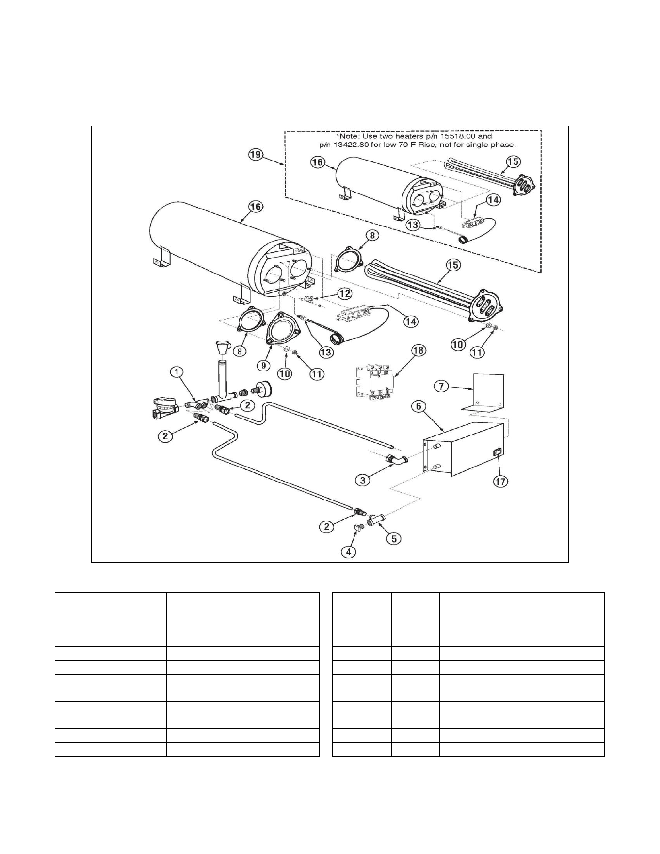
5.2.18. Optional E-Temp Heater (Effective September 1, 2018)
* Note : Use two heaters p/n 15518.00 and 13422.80 for 70 F Rise., not for single phase.
ITEM
NO.
NO.
REQ’D
P/N
DESCRIPTION
ITEM
NO.
NO.
REQ’D
P/N
DESCRIPTION
1
1
13620.20
Booster Heater 1/2 In/Out Adapter
11
6
00912.00
1/4-20 Nylon Lock Nut
2
3
00760.00
5/8 Comp x 1/2 MIP Adapter
12
1
17523.51
Hi Limit Switch 250Deg
3
1
17550.10
Inlet Booster Heater Plumbing Connt
13
1
40116.00
1/4 Comp x 1/4 MIP Ftg
4
1
13642.00
1/2" MIP Plug Brass Sq. Head
14
1
13417.89
Heater Thermostat
5
1
00743.10
1/2 Tee F x F x F Brass
15
1
13422.71
240V 12KW Trianguler Immersion Htr*
6
1
13951.10
E-Temp Booster Shroud - Zoppas
16
1
13422.76
480V 6KW Trianguler Immersion Htr*
7
1
13951.12
E-Temp Booster Access Cover
17
1
13951.20
E-Temp Heater Tank
8
2
15518.11
Gasket for Triangular Flange Heater
18
1
00421.83
Power Rocker Switch, Red
9
1
13950.20
E-Temp Tank Plug for 40F Rise.
19
1
13003.17
Contactor 60 Amp 3 Pole
10
6
00924.00
1/4 SS Washer
20
1
13951.60
E-Temp Tank Assy 70Deg Rise
Parts Manual
MODEL EST-44 Service and Parts Manual Rev. 2 .08A Page
27
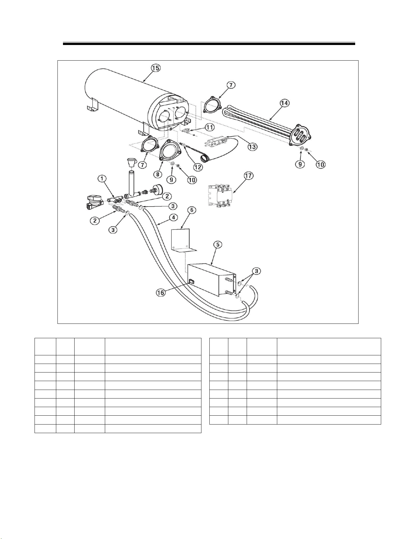
5.2.19. Optional E-Temp Heater
* Note : Use two heaters p/n 15518.00 and 13422.80 for 70 F Rise., not for single phase.
ITEM
NO.
NO.
REQ’D
P/N
DESCRIPTION
ITEM
NO.
NO.
REQ’D
P/N
DESCRIPTION
1
1
13620.20
Booster Heater 1/2 In/Out Adapter
10
6
00912.00
1/4-20 Nylon Lock Nut
2
2
40014.00
1/2m x 1/2 Barb Straight
11
1
17523.51
Hi Limit Switch 250Deg
3
4
03101.47
Hose Clamp # 6 size # 003
12
1
40116.00
1/4 Comp x 1/4 MIP Ftg
4
2
03107.62
Flexible Hose 1/2" X5 Ft
13
1
13417.89
Heater Thermostat
5
1
13951.10
E-Temp Booster Shroud - Zoppas
14
1
13422.71
240V 12KW Triangular Immersion Htr*
6
1
13951.12
E-Temp Booster Access Cover
15
1
13951.20
E-Temp Heater Tank
7
2
15518.11
Gasket for Triangular Flange Heater
16
1
00421.83
Power Rocker Switch, Red
8
1
13950.20
E-Temp Tank Plug for 40F Rise.
17
1
13003.17
Contactor 60 Amp 3 Pole
9
6
00924.00
1/4 SS Washer
Parts Manual
MODEL EST-44 Service and Parts Manual Rev. 2 .08A Page 29
6. Table Limit Switch (P/N 13469.20)
ITEM
NO.
NO. REQ’D
P/N
DESCRIPTION
1
1
13427.12
Connector for Table Limit Switch
2
2
00446.60
Ring Eyelet Connector 14-16 #8
3
14 FT
00547.00
Switch Cord 18 AWG SOOW
4
1
13427.60
Template kit
5
1
13427.61
Mounting bracket
6
1
13427.62
Actuator
7
1
13427.63
Bumper
8
2
03817.00
6-32 wing nut
9
2
03814.10
Lock star washer
10
2
00914.10
1/4-20 x 5/8 hexhead bolt
11
2
00968.00
1/4 split lock washer
12
2
00924.00
1/4 ss washer
13
2
00912.00
1/4-20 nylon lock nut
14
1
13427.10
Limit switch
15
1
13408.64
Switch Bracket Spring
16
1
13427.50
Table Limit Switch Bracket Ass'y
Parts Manual
MODEL EST-44 Service and Parts Manual Rev. 2 .08A Page
30
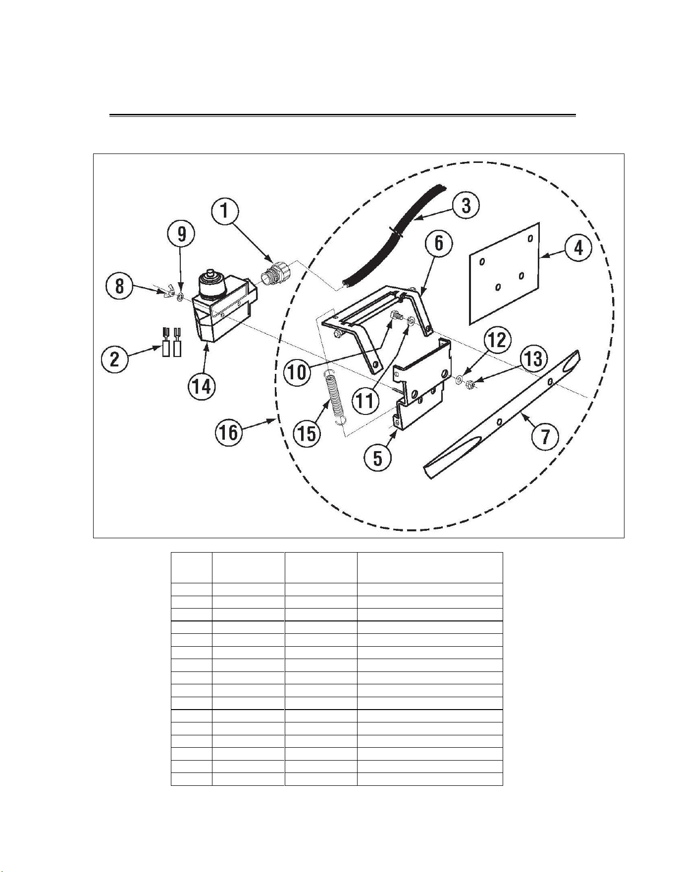
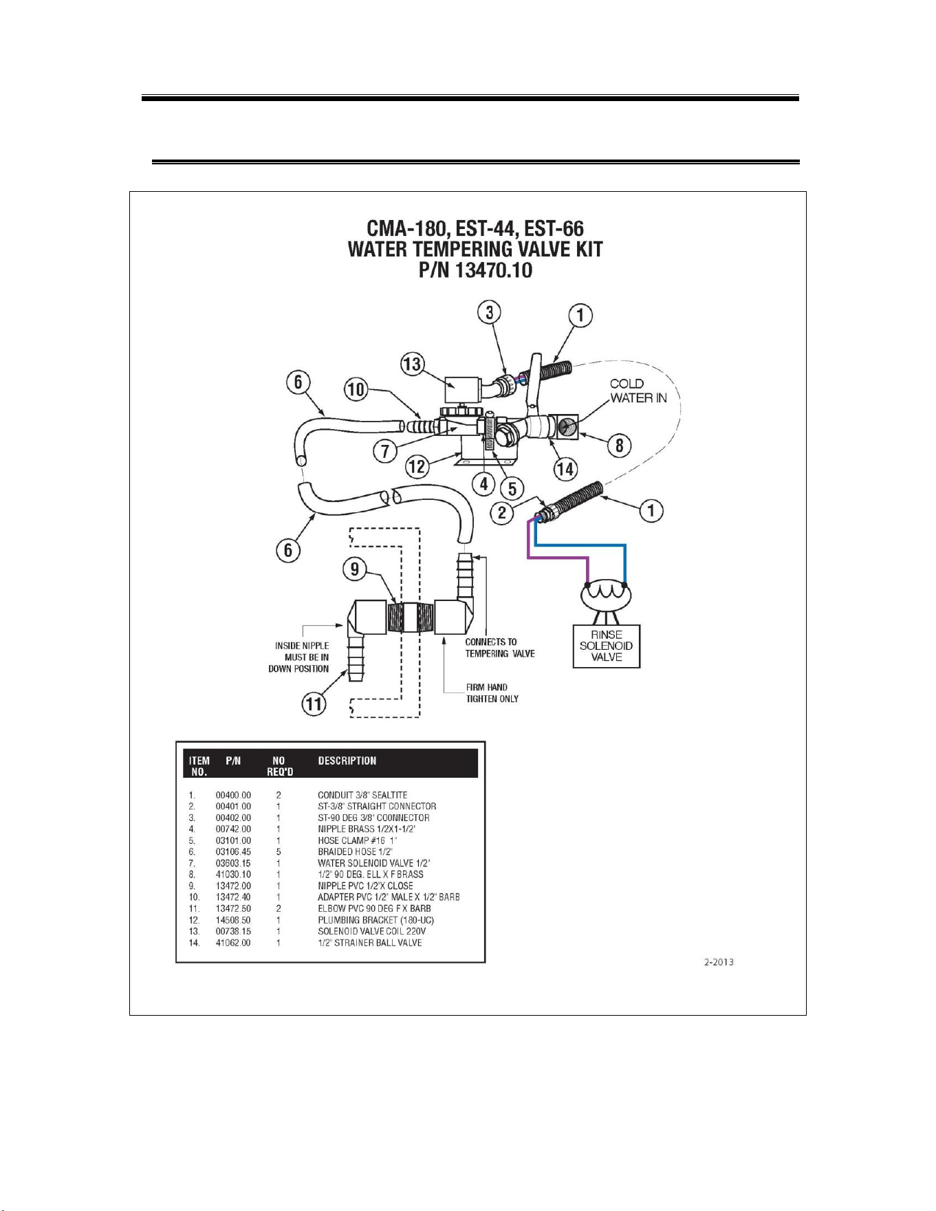
7. Drain Water Tempering Kit (Optional)
Parts Manual
Buy Parts Page 31
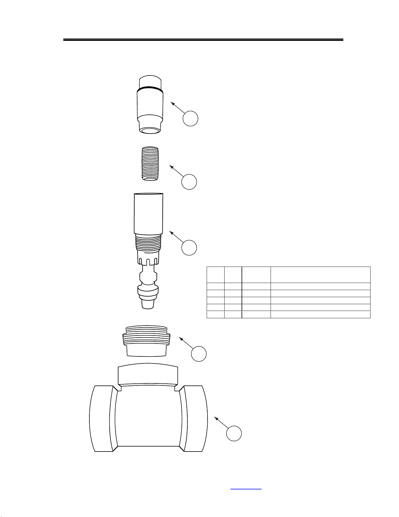
Drain Water Tempering Valve Assembly (Effective 03-2023)
5
ITEM
NO.
NO.
REQ’D
P/N DESCRIPTION
1 1 13470.88 2 ABS Tee S x S x MIP
2 1 13470.87 DTV Adapter 2" X 3/4"
3 1 13470.85 Drain Water Tempering Valve
4 1 00742.00 Nipple Brass 1/2 x 1-1/2
5 1 00715.00 1/2 Ball Check Valve
4
3
2
1
MODEL EST-44 Service and Parts Manual Rev. 2 .08A
Operation
MODEL EST-44 Service and Parts Manual Rev. 2 .08A Page 32
9. Electrical Diagram For E-Temp Heater Only
T
1
L
1
L
3
T
3
T
1
T
2
L
1
L
2
L
3
T
3
T
1
T
2
L
1
L
2
L
3
T
3
M
A
I
N
C
O
N
T
A
C
T
O
R
T
1
T
2
T
3
L
1
L
2
L
3
L
3
L
2
L
1
T
3
T
2
T
1
1
1
A
2
A
A
2
C
Y
C
L
E
S
T
A
R
T
T
R
I
P
S
W
I
T
C
H
P
O
W
E
R
S
W
I
T
C
H
3 2
7
A
U
T
O
M
A
N
U
A
L
F
I
N
A
L
R
I
N
S
E
T
R
I
P
S
W
I
T
C
H
W
A
T
E
R
S
O
L
E
N
O
I
D
V
A
L
V
E
R
I
N
S
E
W
A
T
E
R
S
O
L
E
N
O
I
D
V
A
L
V
E
D
O
O
R
S
A
F
E
T
Y
S
W
I
T
C
H
N
O
T
E
1
N
O
T
E
2
,
3
N
O
T
E
4
,
5
220V SIGNAL
FOR
FAN M
OT
O
R
CONTROL CONTACTOR
COIL.
CMA KIT PN13578.00
3
A
M
P
S
L
O
W
B
L
O
W
F
U
S
E
(
x
2
)
G
R
O
U
N
D
A
2
P
U
M
P
M
O
T
O
R
A
A
T
1
T
2
L
1
L
2
L
3
T
3
1
C
O
N
V
M
O
T
O
R
1
2
3
6
RINSE
THERMOSTAT
T
A
N
K
H
E
A
T
E
R
3
k
W
L
2
T
2
A
1
A
2
07/2023
Rev.
2
.
0
5
WASH HEATER
CONTACTOR
RINSE HEATER
CONTACTOR
RINSE PUMP
CONTACTOR
WASH PUMP
CONTACTOR
CONVEYOR
CONTACTOR
CONVEYOR
TIMER
WASH
THERMOSTAT
WASH
TANK
PRE-RINSE
TANK
3
:
C
O
N
N
E
C
T
O
N
L
Y
T
O
P
R
I
M
A
R
Y
O
F
L
I
S
T
E
D
C
L
A
S
S
2
T
R
A
N
S
F
O
R
M
E
R
2
0
8
-
2
3
0
V
6
0
H
z
M
A
X
I
M
U
M
1
0
0
V
A
.
1
:
T
A
B
L
E
L
I
M
I
T
S
W
I
T
C
H
C
O
N
N
E
C
T
I
O
N
P
R
E
-
W
I
R
E
D
A
T
F
A
C
T
O
R
Y
.
N
O
T
E
S
:
2
:
S
A
N
I
/
R
I
N
S
E
.
S
I
G
N
A
L
I
S
O
N
W
H
E
N
F
I
N
A
L
R
I
N
S
E
I
S
A
C
T
I
V
E
.
4
:
D
E
T
E
R
G
E
N
T
F
E
E
D
E
R
S
I
G
N
A
L
A
N
D
F
A
N
M
O
T
O
R
C
O
N
T
R
O
L
C
O
N
T
A
C
T
O
R
C
O
I
L
.
6
:
D
I
S
P
E
N
S
E
R
P
O
W
E
R
B
L
O
C
K
2
0
8
-
2
4
0
V
O
L
T
S
CHEMICAL
DISPENSER
208-230V
N
O
T
E
6
5
:
C
O
M
B
I
N
E
D
L
O
A
D
O
F
U
S
E
R
D
E
V
I
C
E
S
(
C
H
E
M
I
C
A
L
P
U
M
P
S
,
F
A
N
C
O
N
T
R
O
L
S
,
E
T
C
.
)
M
U
S
T
N
O
T
E
X
C
E
E
D
1
A
M
P
.
TANK
HEATER
10kW
T1
T2
T3
OVERLOAD
1.6A- 2.5A
95
P
U
M
P
M
O
T
O
R
(
2
3
0
VAC
s
i
n
g
l
e
-
p
h
a
s
e
,
d
u
a
l
f
l
o
a
t
s
)
WIRE DIAGRAM FOR MODEL: EST-44
Buy Parts Page 35
MODEL EST-44 Service and Parts Manual Rev. 2 .08A