
www.cmadishmachines.com
Table of Contents
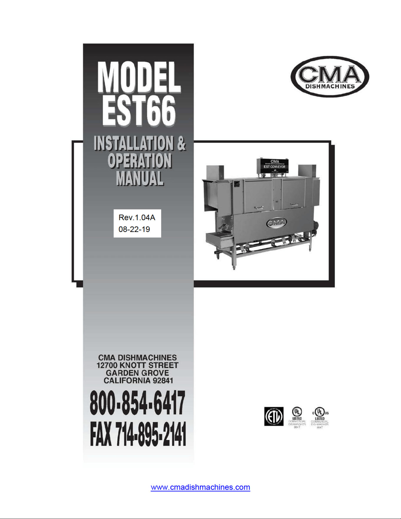
EST-66
1. SPECIFICATIONS................................................................................................. 2
1.1. EST- 66 ........................................................................................................................................... 2
2. GETTING STARTED ............................................................................................ 3
2.1. Introduction to CMA Model EST -66............................................................................................. 3
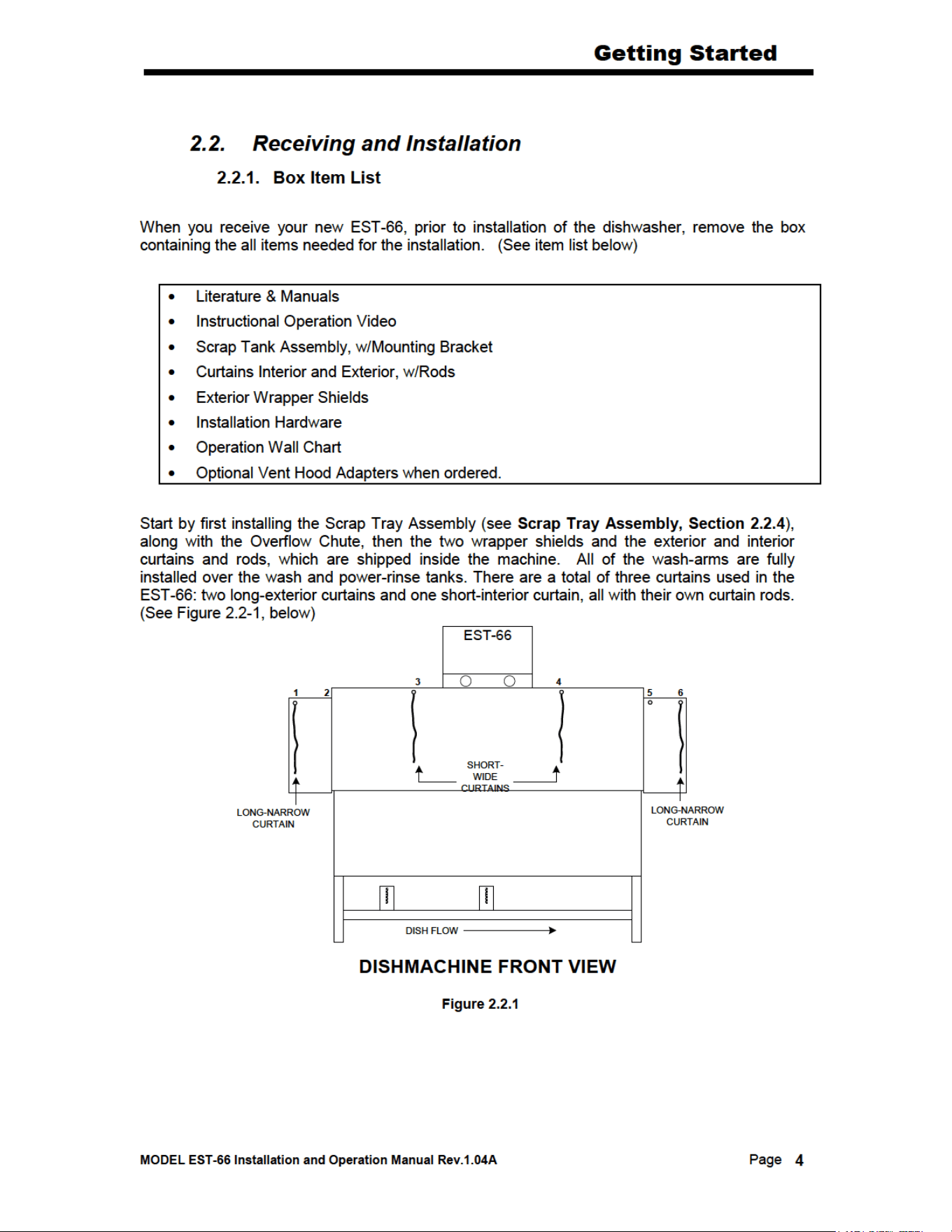
2.2. Receiving and Installation .............................................................................................................. 4
2.2.1. Box Item List ........................................................................................................................... 4
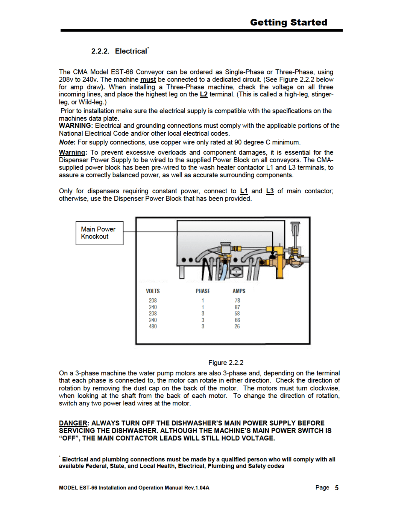
2.2.2. Electrical ................................................................................................................................ 5
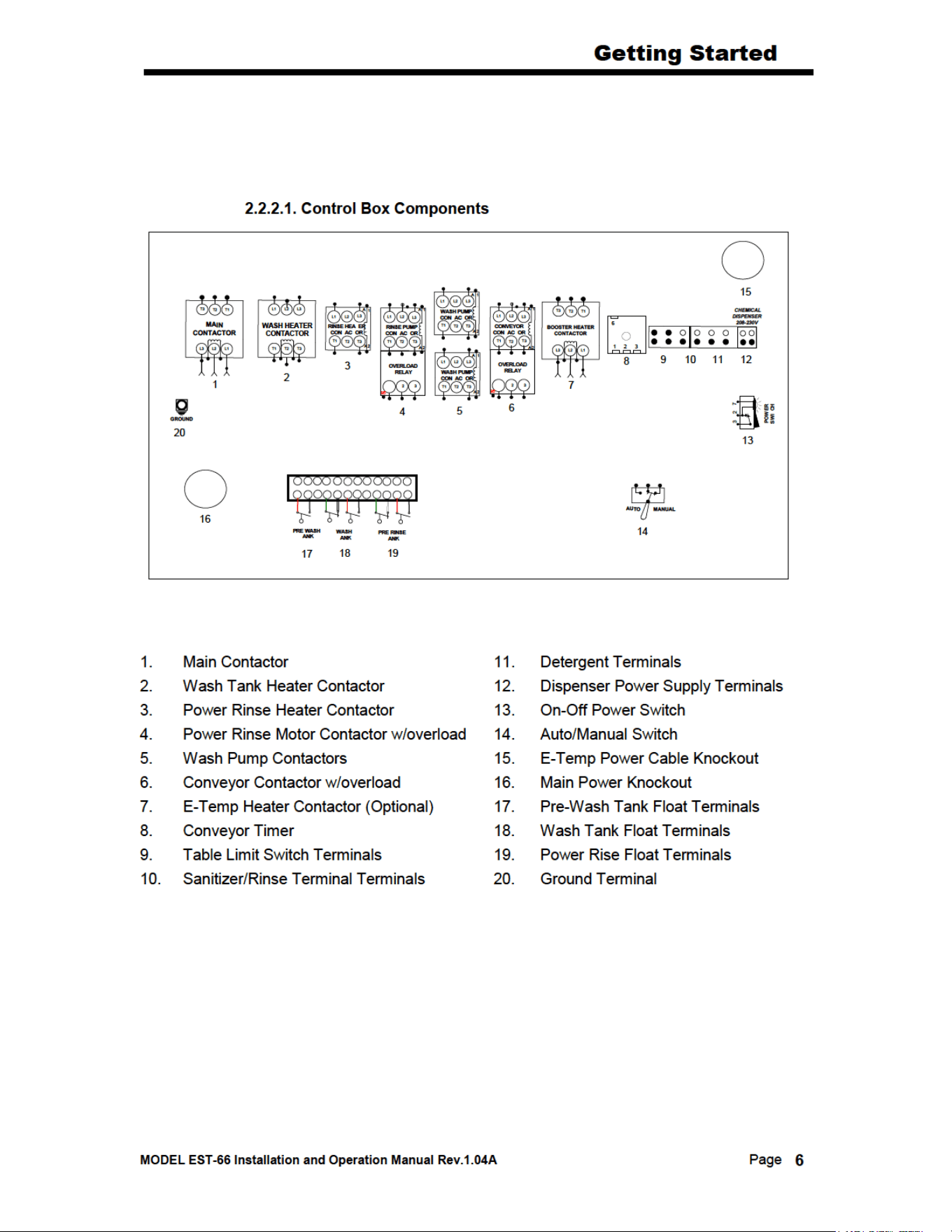
2.2.2.1. Control Box Components ............................................................................................... 6
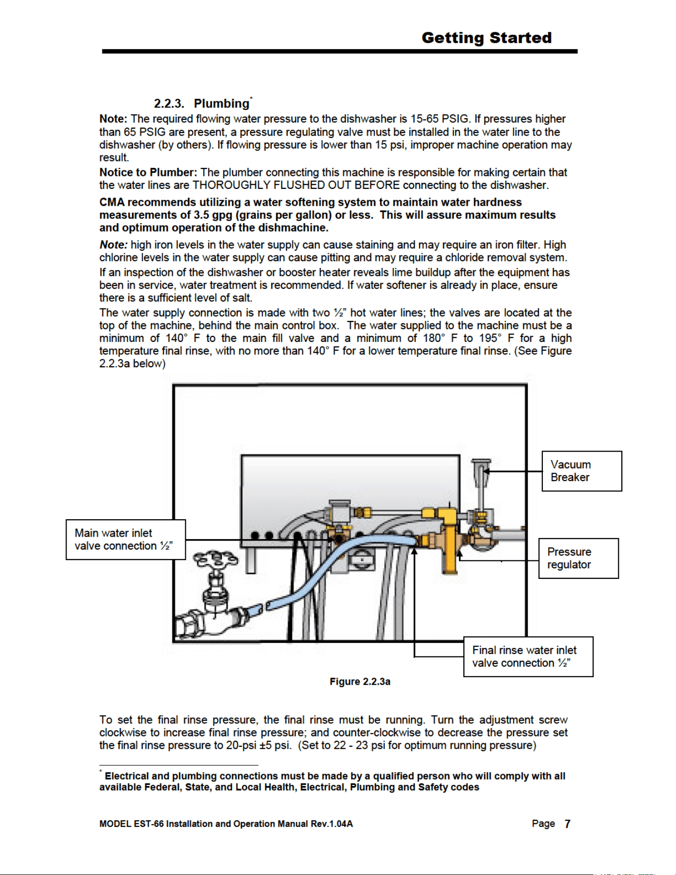
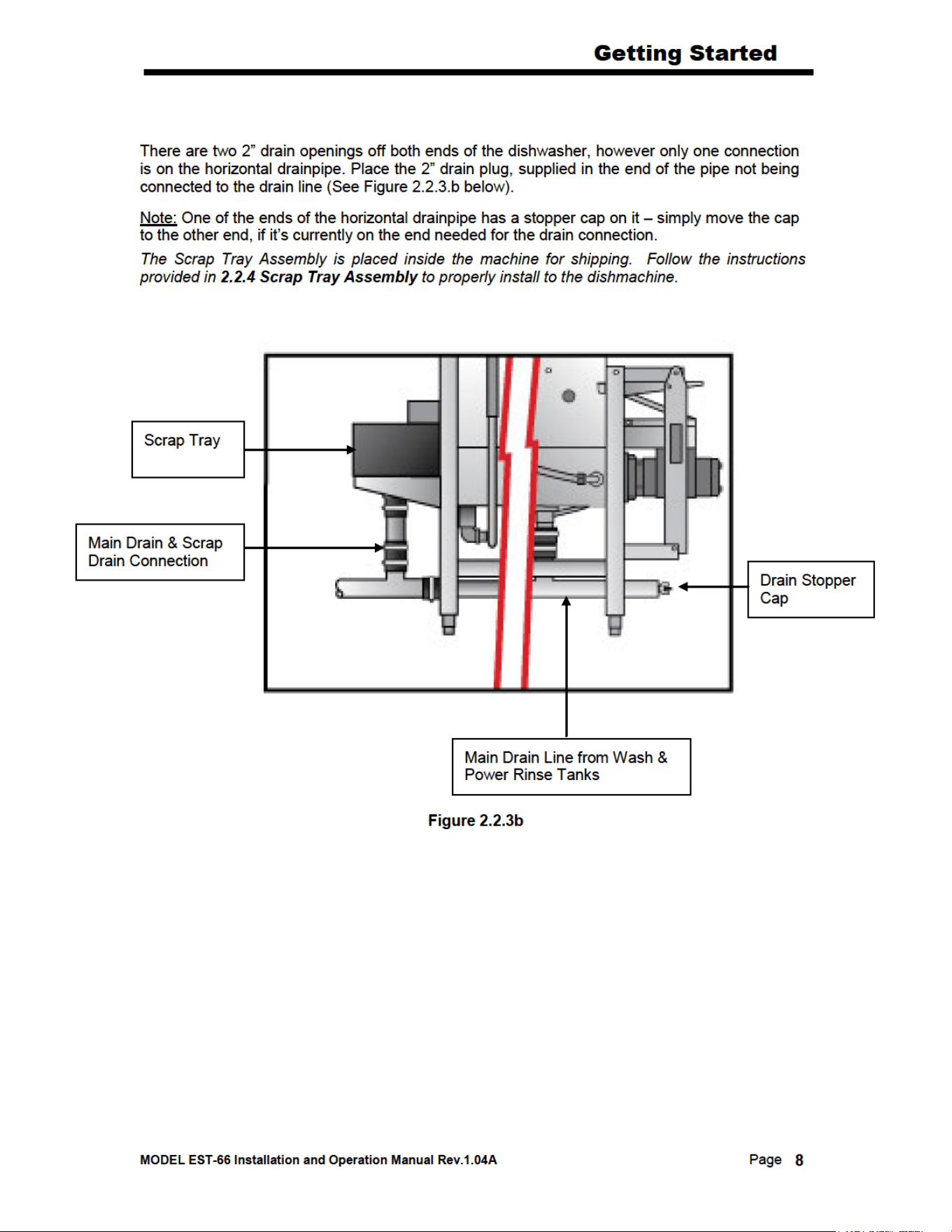
2.2.3. Plumbing ................................................................................................................................. 7
2.2.4. Scrap Tray Assembly Installation ........................................................................................... 9
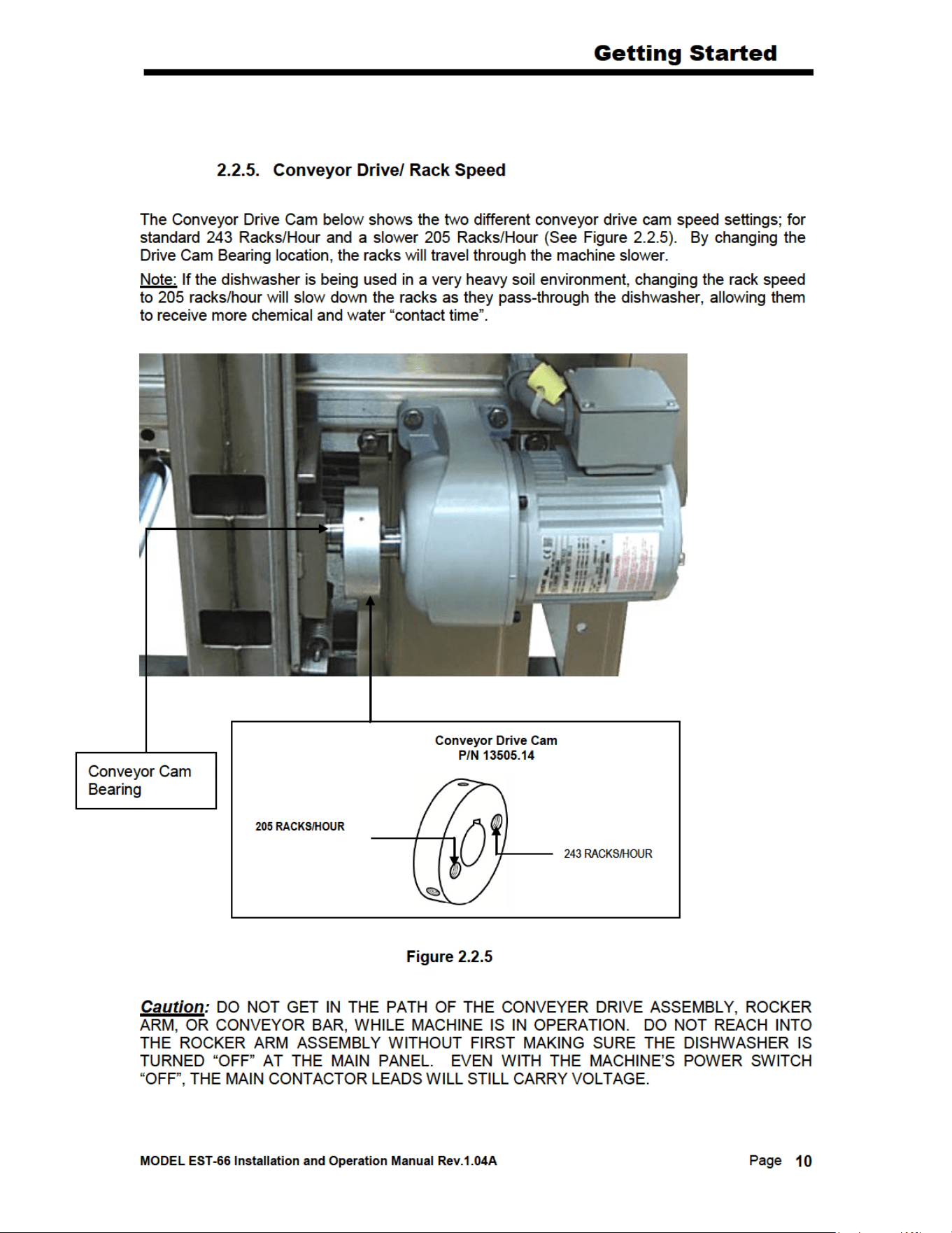
2.2.5. Conveyor Drive/ Rack Speed .................................................................................................10
2.2.6. Wash Pump Assembly and Impeller .......................................................................................11
2.2.7. Table Limit Switch Installation ..............................................................................................12
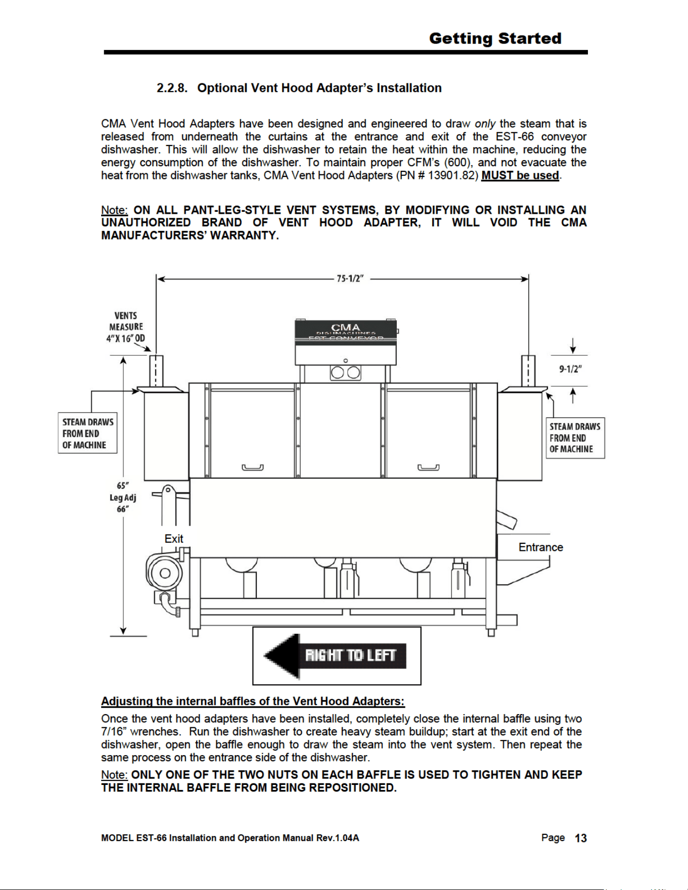
2.2.8. Optional Vent Hood Adapter’s Installation ...........................................................................13
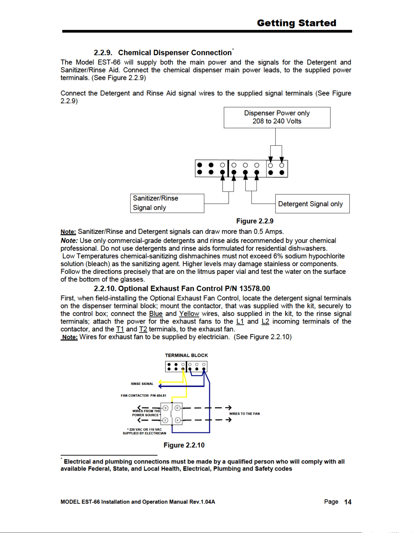
2.2.9. Chemical Dispenser Connection ...........................................................................................14
2.2.10. Optional Exhaust Fan Control P/N 13578.00 .......................................................................14
2.2.11. (Optional) E-Temp Booster Heater .......................................................................................15
2.3. EST-44 Safety Tips .......................................................................................................................16
3. OPERATION ........................................................................................................ 17
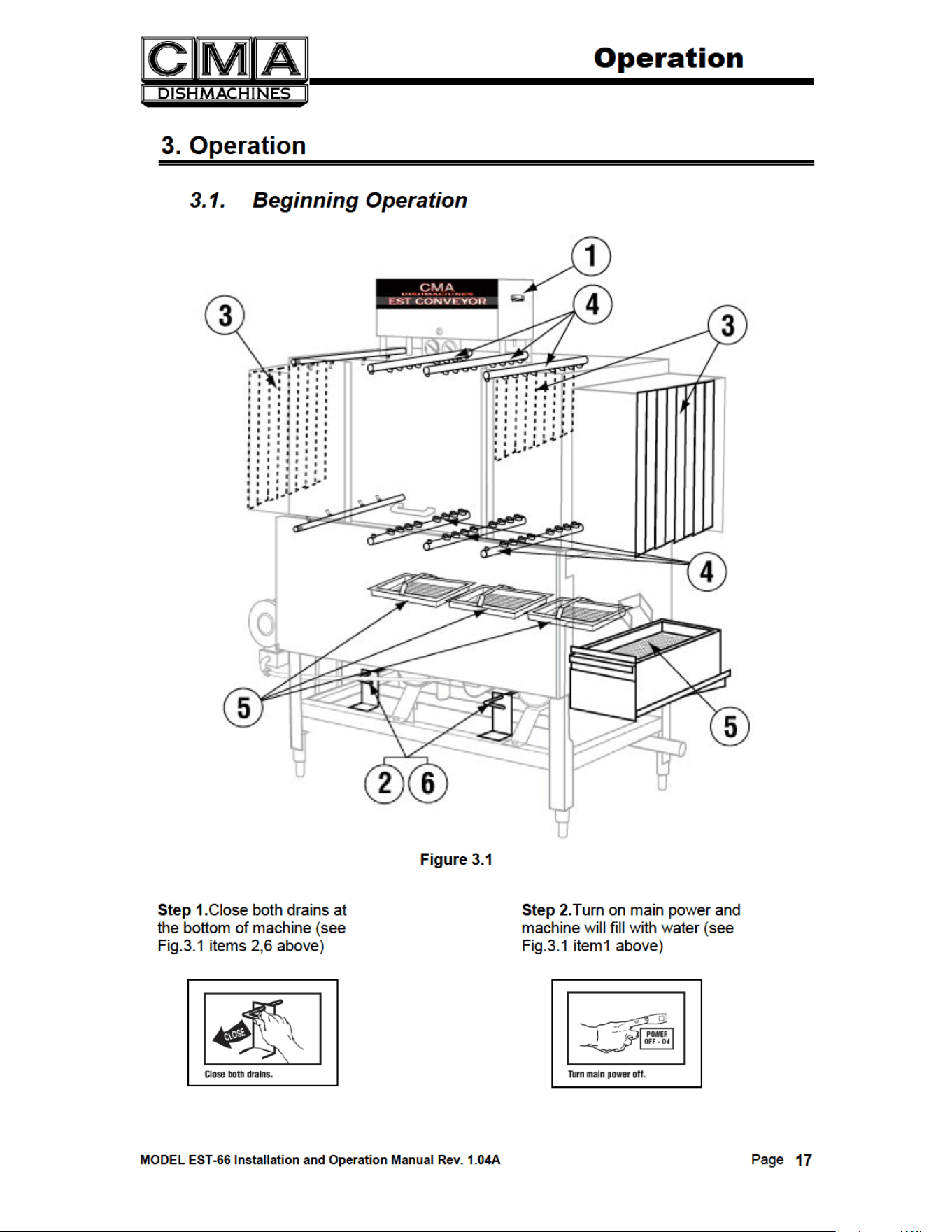
3.1. Beginning Operation ......................................................................................................................17
3.2. Cleaning Instructions .....................................................................................................................19
3.3. Regular Service and Maintenance Checklist .................................................................................20
3.4. Trouble Shooting ...........................................................................................................................21
3.5. Drain Water Tempering Kit (Optional) ..............................................................................22 & 22a
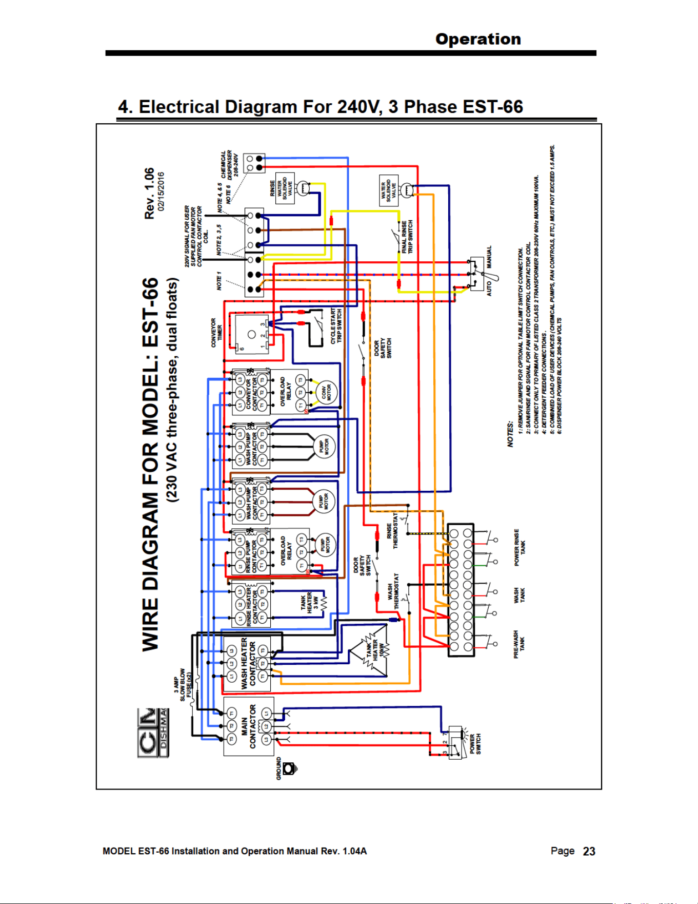
4. ELECTRICAL DIAGRAM FOR 240V, 3 PHASE EST-66 ............................. 23
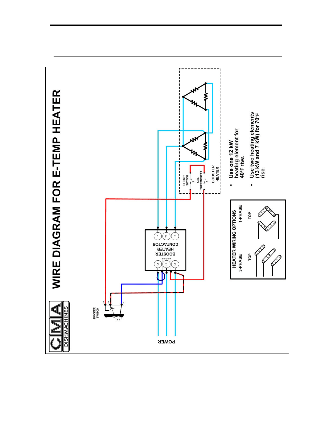
5. ELECTRICAL DIAGRAM FOR E-TEMP HEATER ONLY ......................... 24
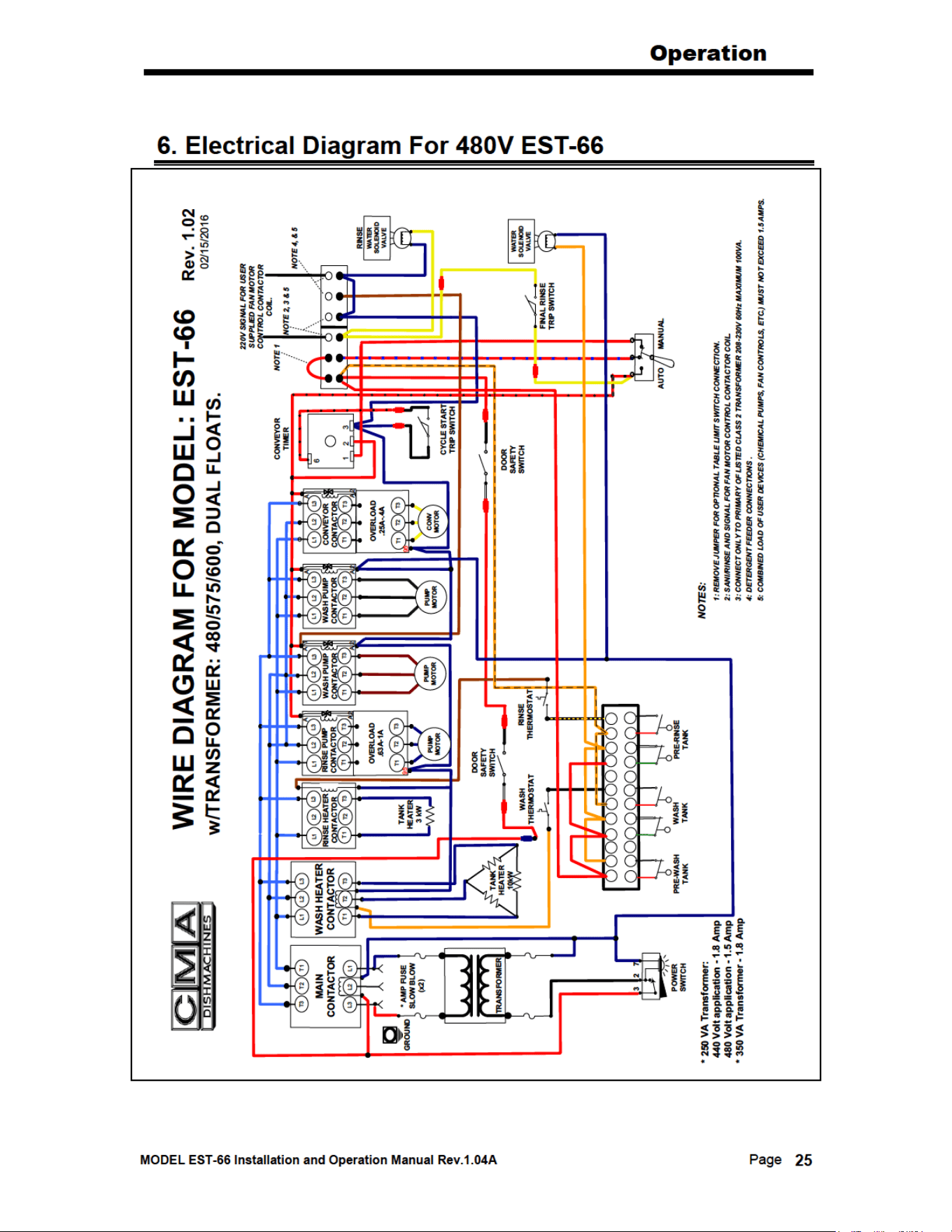
6. ELECTRICAL DIAGRAM FOR 480V EST-66 ................................................ 25
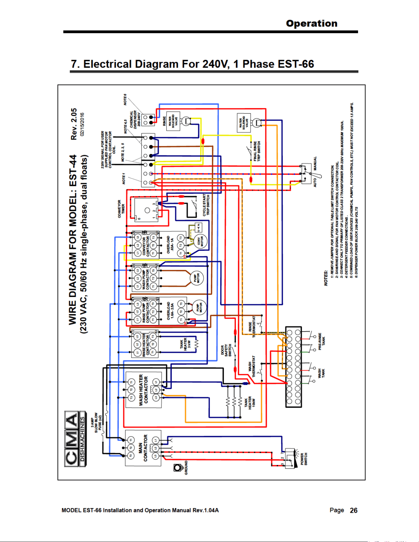
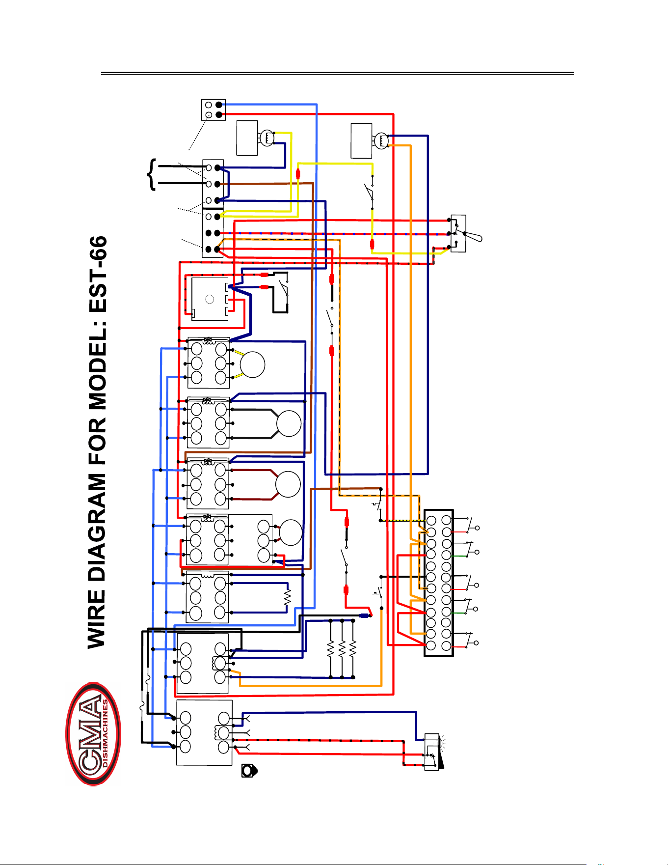
7. ELECTRICAL DIAGRAM FOR 240V, 1 PHASE EST-66 .................... 26 & 27

MODEL EST-66 Installation and Operation Manual Rev.1.04A Page
2
1. Specifications
1.1. EST- 66
WATER CONSUMPTION
PER RACK (FINAL RINSE) .46 GAL. .46 GAL.
PER HOUR (FINAL RINSE) 114 GAL. 114 GAL.
CONVEYOR SPEED
FEET PER MINUTE 6.75 6.75
OPERATING CAPACITY
RACKS PER HOUR (NSF rated) 249 249
OPERATING TEMPERATURE
WASH RECOMMENDED 140° - 150° F 150° - 160° F
PUMPED RINSE RECOMMENDED 140° - 150° F 150° - 160° F
FINAL RINSE RECOMMENDED 140° - 150° F 180° - 195° F
WATER REQUIREMENTS
INLET TEMPERATURE (MIN) 140° F 180° F
WATER INLET SIZE 1/2”
FINAL RINSE SIZE 1/2”
DRAIN SIZE 2”
FINAL RINSE PRESSURE 20 PSI
HEATERS
WASH HEATER 13.3 KW/240V(1 phase)
13KW/208V(3 phase)
RINSE HEATER 3KW/240V, 2.25KW/208V
MOTORS
WASH PUMP (2) 1 HP
RINSE PUMP 1/3 HP
CONVEYOR 1/8 HP
DIMENSIONS
DEPTH 25-1/8”
WIDTH 66”
HEIGHT 55 -1/2”-56-1/2”
STANDARD TABLE HEIGHT 32 ½” adjusts to 34”
MAX CLEARANCE FOR DISHES 19”
STRANDARD RACKS 19 ¾” x 19 ¾”
SHIPPING WEIGHT
810#
(367kg)
VOLTS PHASE AMPS AMPS(Tall)
ELECTRICAL RATING 208
1 78 N/A
240 1 87 N/A
208 3 58 64
240 3 66 72
480 3 26 29
EST-66
H.T.
EST-66
L.T.

Getting Started
MODEL EST-66 Installation and Operation Manual Rev.1.04A Page
9
2.2.4. Scrap Tray Assembly Installation
The Scrap Tray Assembly and Overflow Chute, which were shipped inside the machine, can
easily be installed by executing the following steps: Figure 2.2.4 below illustrates the assembly,
as it would appear for a Left-to-Right machine – (a Right-to-Left machine would simply be the
mirror image).
Caution:
1. For proper spacing, the SS flat washer must not be located between the head of the truss
head bolt and the inside of the machine.
2. The Illustration below shows the correct placements of the scrap trap holder. Do not
install upside down, otherwise water deflection takes place.
Figure 2.2.4
1. Remove items from their packaging and verify that all “installation hardware” was included.
2. Secure the scrap trap holder to the dishmachine by using the four ¼-20 X ½” Hex Head
Bolts, the ¼” SS Flat Washers, and the ¼”-20 Nylon Lock Nuts that were provided.
3. Set the scrap trap body—with the scrap trap drawer inserted—into position on the scrap trap
holder. (Attach the drain as specified in Section 2.2.3)
Getting Started
MODEL EST-66 Installation and Operation Manual Rev.1.04A Page
11
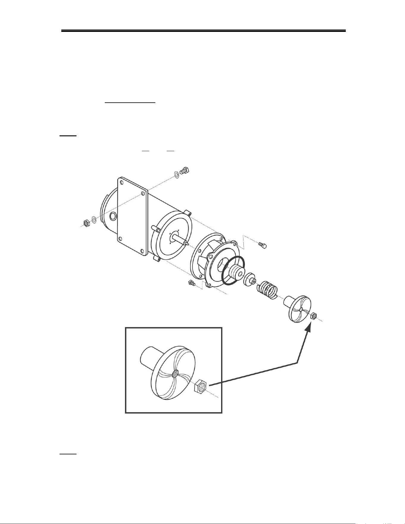
2.2.6. Wash Pump Assembly and Impeller
The standard wash pump motor is three-phase and can operate clockwise, as well as counter-
clockwise; the Nylon Lock Nut
used to hold the impeller in place (See Figure 2.2.6), is very
important. When servicing the Wash Pump Assembly and replacing the seals, make sure it is
secured properly; otherwise, if the motor turns the wrong direction, the impeller may spin-off the
motor shaft causing damage to the impeller.
Note: ALWAYS CHECK THAT THE DIRECTION OF THE MOTOR ROTATION IS CLOCKWISE,
WHEN REINSTALLING THE WASH PUMP. IF THE MOTOR IS TURNING COUNTER-
CLOCKWISE, EXCHANGE L1
AND L3 WIRES ON MAIN CONTACTOR
Figure 2.2.6
Note: The Nylon Lock Nut indicated by the arrow in Figure 2.2.6 must be removed before
attempting to remove the water pump impeller.
Getting Started
MODEL EST-66 Installation and Operation Manual Rev.1.04A Page
12
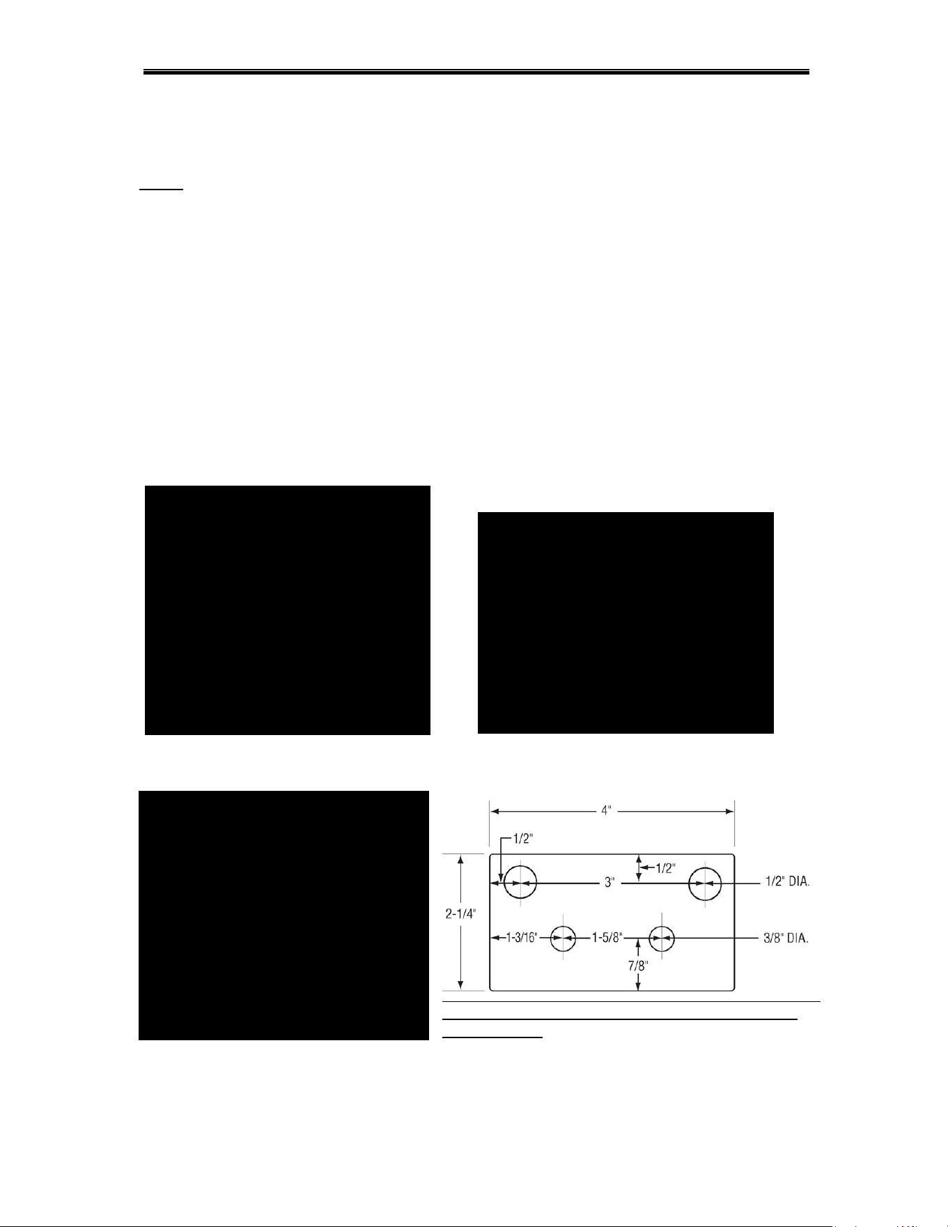
2.2.7. Table Limit Switch Installation
The Model EST-66 is shipped with a Table Limit Switch fully wired and connected in the main
control box, ready to be installed on the clean side of the dishtable. The Table Limit Switch
MUST
be installed to prevent dishrack and Conveyor Drive damage.
1. Remove the template that was shipped to hold the table-limit switch assembly
together
.
2. Remove the activator bar (Figure 2.2.7a).
3. Position the template in the middle of the clean side of the dishtable.
4. Mark the end of the table, where the holes need to be drilled (Figure 2.2.7b).
5. Drill the holes.
6. Attach the Table Limit Switch, using the hardware supplied.
7. Reattach the activator bar removed earlier.
8. Test that it functions properly (Figure 2.2.7c).
Figure 2.2.7a Figure 2.2.7b
Note: This terminal is not actual size ,not to be used
for installation!
Figure 2.2.7c
Getting Started
MODEL EST-66 Installation and Operation Manual Rev.1.04A Page
15
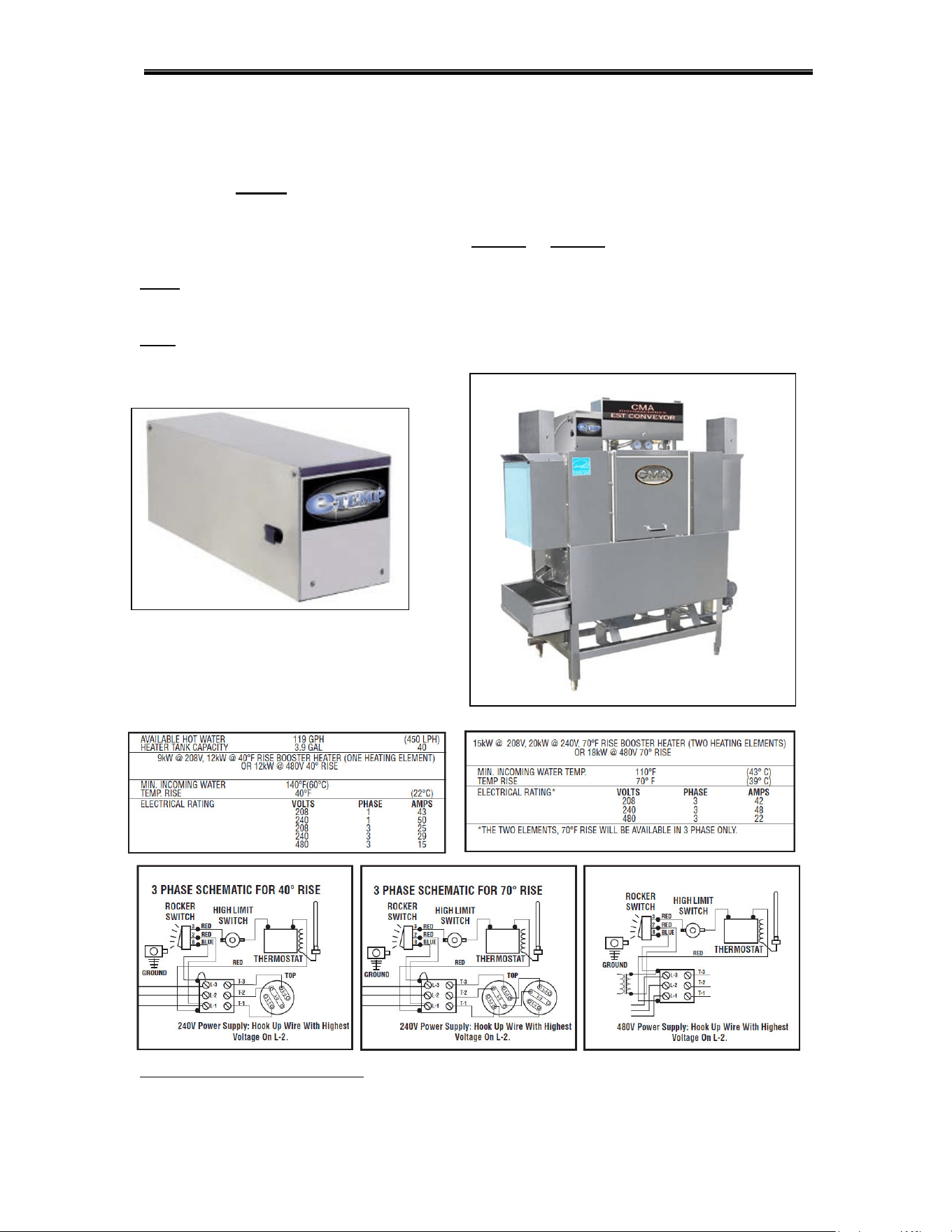
2.2.11. (Optional) E-Temp Booster Heater
*
The Optional E-Temp Booster Heater can only be ordered with a dishwasher, already installed at
the factory; it cannot
be installed in the field. The E-Temp Booster heater will be fully integrated
into the EST-66 conveyors’ plumbing system. It will require its’ own power supply of 208 volts to
240 volts, in single-phase or three-phase. The unit can be specially ordered as a 480-volt unit, in
three-phase only; temperature is available in a 40° rise
or 70° rise. The E-Temp Booster heater
contactor is located in the EST-44 Main Control Box (See item 7, page 6).
Note: E-Temp heater is shipped on the machine empty to prevent freezing. When machine
is powered up for the first time, the booster heater must be filled by pressing and holding
rinse switch to prevent heater damage.
Note: 70° degree rise E-temp Booster Heater is only available in Three-Phase.
*
Electrical and plumbing connections must be made by a qualified person who will comply with all
available Federal, State, and Local Health, Electrical, Plumbing and Safety codes

Getting Started
MODEL EST-66 Installation and Operation Manual Rev.1.04A Page
16
2.3. EST-44 Safety Tips
DANGER:
Always turn off the main
circuit breaker at the wall when
installing or servicing this dishmachine and/or an E-Temp
Booster Heater. Even with the machine’s power switch “off”,
there is a live connection
being carried to the switch from the
dishmachine contactor.
CAUTION:
Do not get in the path of the Conveyor Rocker Arm or the
conveyor’s moving bar. Do not
reach into the rocker arm area
without first making sure the dishmachine is turned “off” at the
circuit breaker.
CAUTION:
Do not open the front door when the machine is in operation.
CAUTION: Avoid spraying water on or around the electrical control box
located on the top of the machine. When cleaning, do not
spray water directly on the motors.
CAUTION:
When removing the Final Rinse Arms for cleaning, exercise
caution. The Final Rinse Arms may be filled with chemicals or
have additional pressure applied.
Operation
MODEL EST-66 Installation and Operation Manual Rev.1.04A Page
18
Step 3.Allow machine to
come to temperature
Step 4.Rinse rack
thoroughly
Step 5.Place rack in
entrance
Step 6.Remove dishes
from rack
Step 7.Place
properly in rack
Step 8.Pre-soak flatware
Step 9.Wash flatware
Step 10.Place flatware in containers
with handles down; wash a second
time
Operation
MODEL EST-66 Installation and Operation Manual Rev.1.04A Page
19
3.2. Cleaning Instructions
See Fig.3.1, Items 2,6 See Fig.3.1, Items 4 See Fig.3.1, Items 5 See Fig.3.1, Items 3

Operation
MODEL EST-66 Installation and Operation Manual Rev.1.04A Page
20
3.3. Regular Service and Maintenance Checklist
Check all electrical connections, assuring they are tight and secure.
Check all Water, Drain, and Plumbing connections for leaks; tighten if needed.
Check Final Rinse Arms: the Rinse Jet Spray should be straight up & down.
Check Wash Pump motor rotation, making sure it is turning clockwise.
Check Dish rack Movement, Conveyor Arm & Bar, and Conveyor Dog Alignment.
Check Tray Track Guide and Rail & Table Alignment throughout dishwasher.
Check Timer Dipswitch Setting; only switch 6 should be in “on” position (32 seconds)
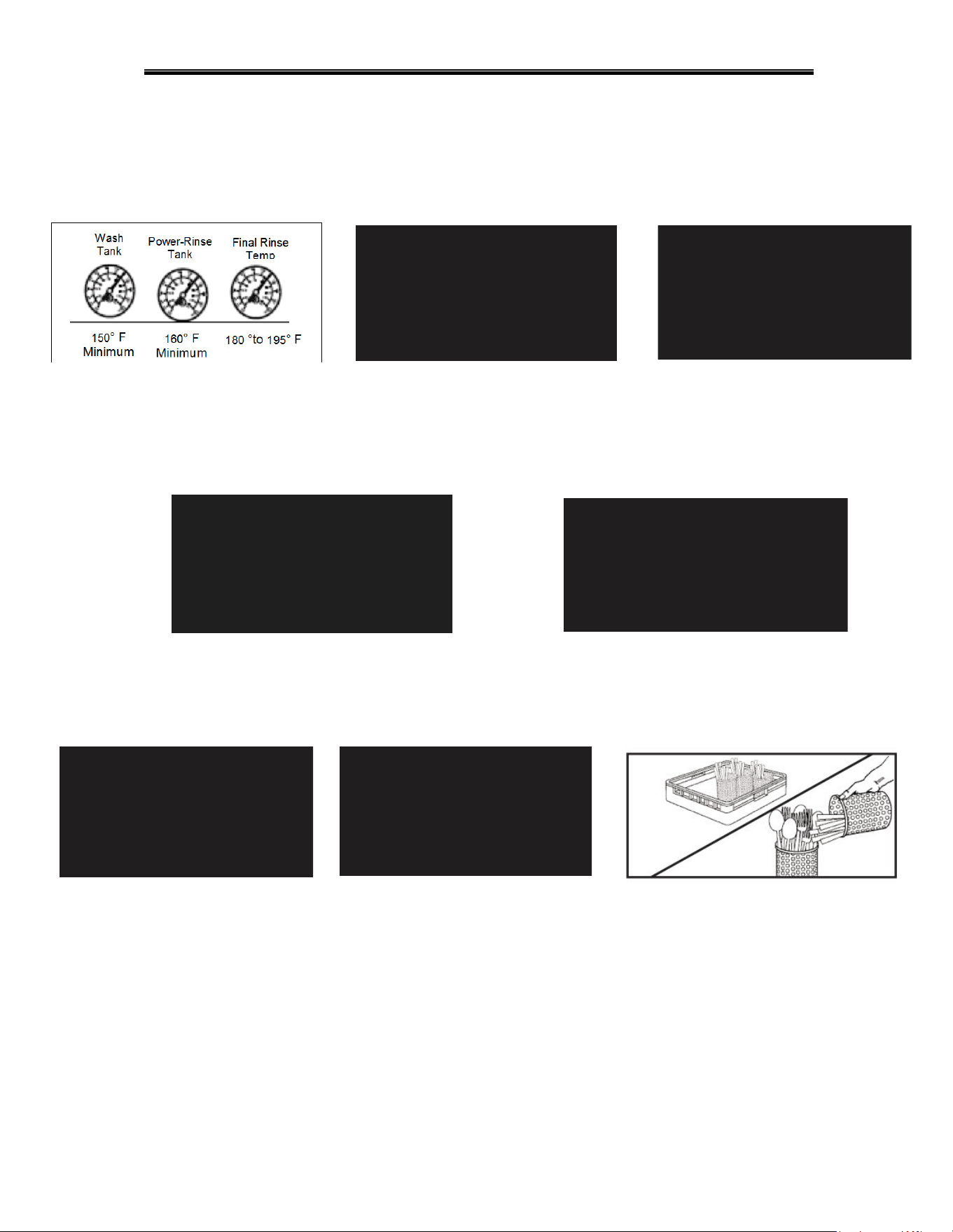
Check Wash-Tank Temperature 150° F Minimum.
Check Power-Rinse Tank Temperature 160° F Minimum.
Check Final-Rinse Temperature 180° to 195° F (High-Temp)
(140° F for Low Temp)
Check Final Rinse Pressure 20 psi, ±5 psi
Check Table-Limit Switch operation (If not installed, Warranty will be voided)
Check Vent Hood adapter baffle position to draw steam. (Optional)
(Keep baffles open to a minimum)
Check and make sure the dishwasher is level.
Check to make sure all curtains are in place.
Read all labeling and follow procedures.
Review installation section before beginning the installation of the Model EST-66
Conveyor Dishwasher. All installation procedures and guidelines MUST
BE followed
precisely.
Operation
MODEL EST-66 Installation and Operation Manual Rev.1.04A Page
21
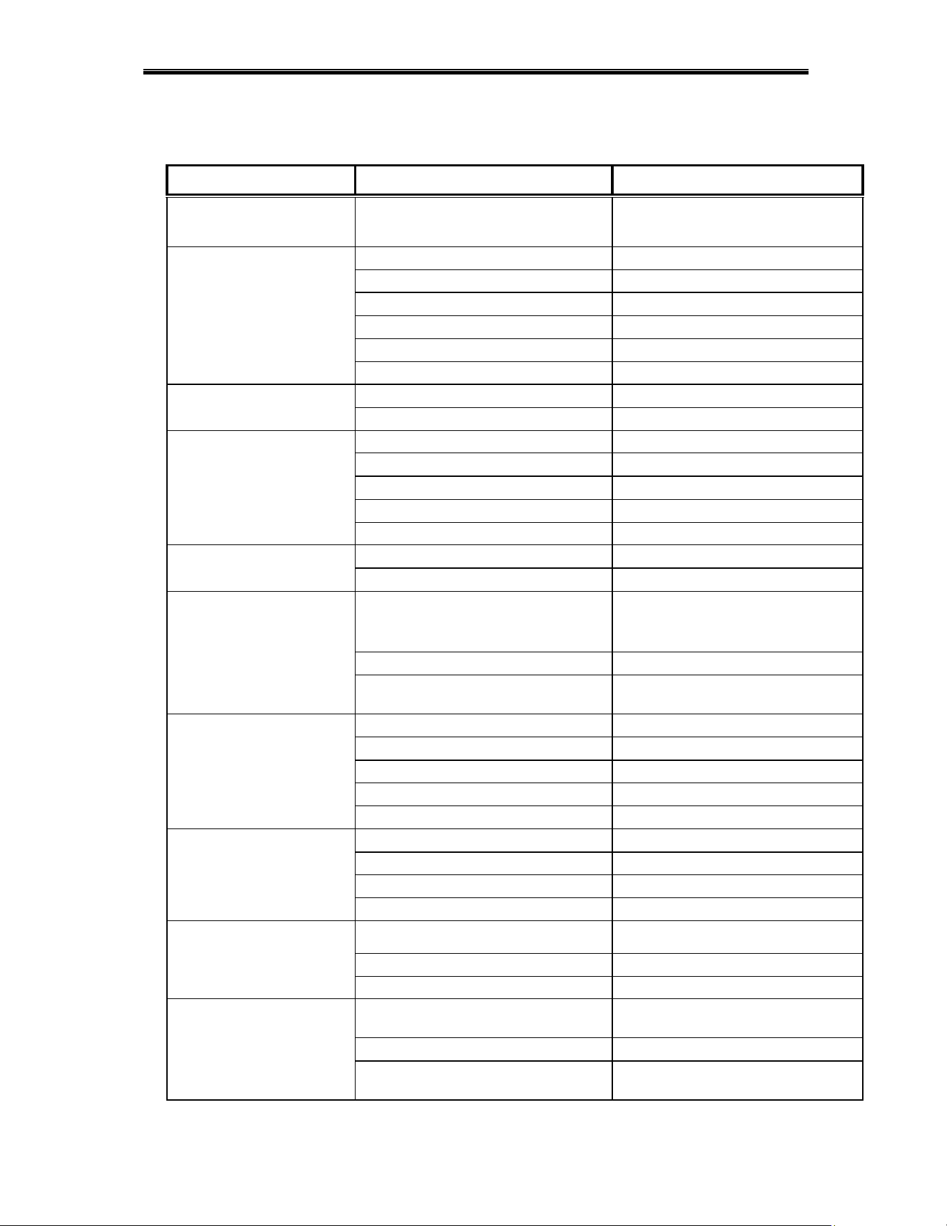
3.4. Trouble Shooting
PROBLEM LIKELY CAUSE SOLUTION
Wash or power rinse
motor not running
Bad motor or capacitor
Faulty contactor
Replace defective motor or
Replace contactor
Machine inoperative
Fuse is burned out Replace fuse
Table limit switch Remove dish rack at switch
Defective door reed switch Replace reed switch
Defective start reed switch Replace reed switch
Defective auto/manual switch Replace switch
Defective Conveyor Timer Replace timer
Machine runs continuously
Timer or settings@ 60 Sec Replace timer or change settings
Contactor stuck Replace contactor
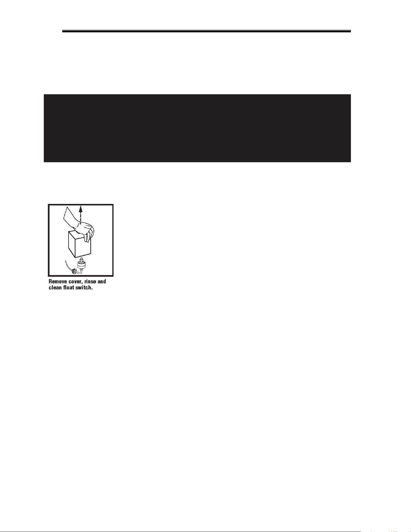
Heater (no heat)
Float switch Check movement-replace it
Defective thermostat or setting Replace thermostat or adjust
Defective heater contactor Replace heater contactor
Defective heater Replace heater
Wire connections Check and correct
Racks stuck
Old or broken rack Replace rack
Tray track alignment Adjust track to table properly
Wash & Power rinse tank
temperature low
Incoming water supply
(Low temp 120°F-Recommende140°F;
High temp 180°F minimum)
Check hot water supply
Thermostat setting Adjust thermostat to mach NSF label
Vent hoods baffle setting Set CMA Vent hood adapter baffles as
instructed on page 13
Low final rinse pressure or
no rinse pressure
Plugged rinse jets Remove and clean
Pressure regulator out of adjustment Adjust pressure regulator20psi to 23psi
Water sol. valve coil or diaphragm Replace or clean
Dirty rinse jets Remove and clean jets
Defective rinse reed switch Replace reed switch
Machine using too much
chemical
Quick drain on wash end Plumb quick drain back into wash tank
Dispenser or settings Check dispenser troubleshooting guide
Rinse pressure Set 20 psi.
Soil Check scrap basket sand float function
Machine loosing water
Quick drain on dirty side table Check quick drain connections
Sheet pans Use CMA sheet pan rack
Drain valves open Close completely
Low wash arm pressure
Debris In wash & power rinse arm
manifolds
Remove arm, check & clean debris from
manifolds
Clogged jets Clean jets
Motors connected wrong Connect motors to reverse impeller
direction
Operation
MODEL EST-66 Installation and Operation Manual Rev.1.04A Page
22
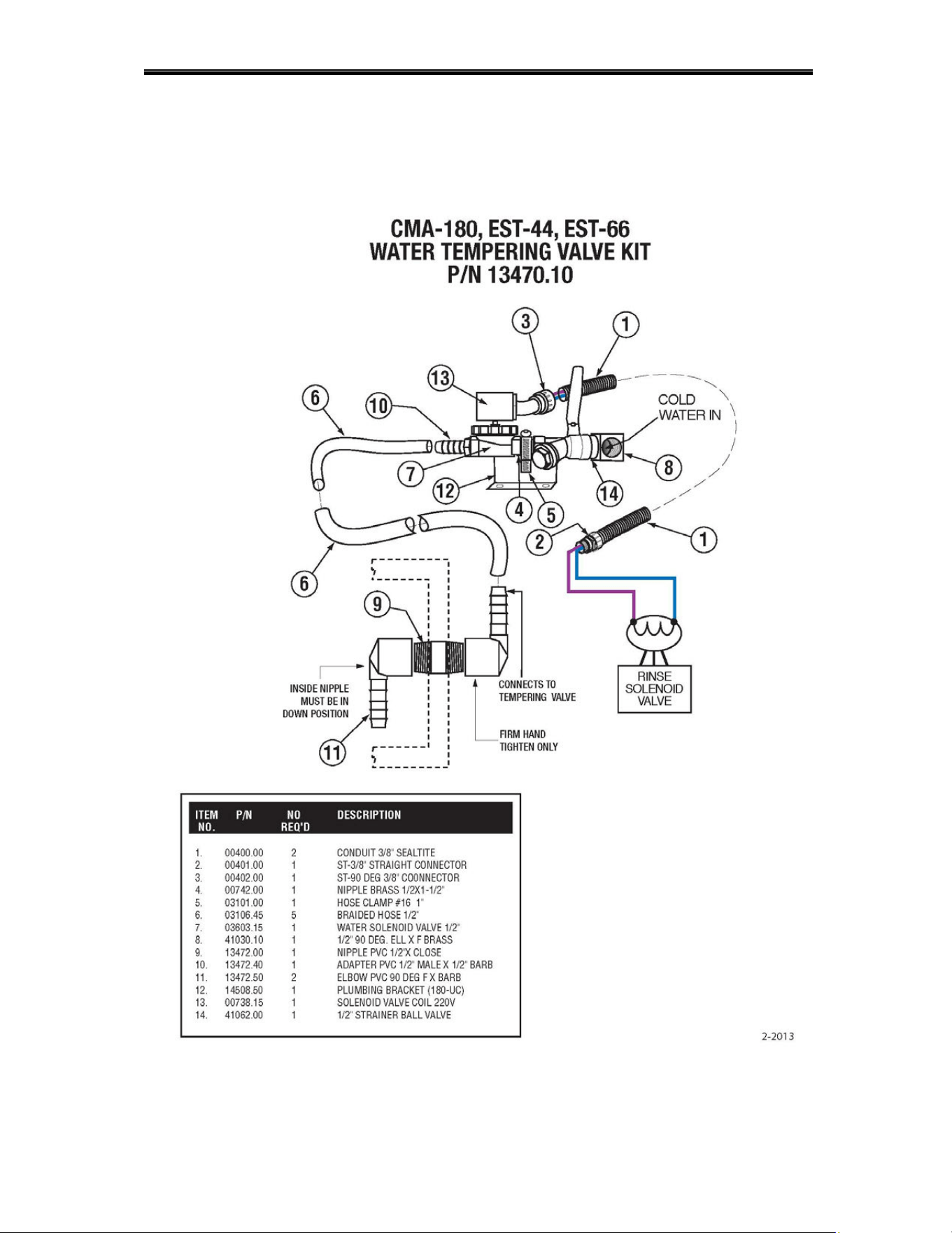
3.5. Drain Water Tempering Kit (Optional)
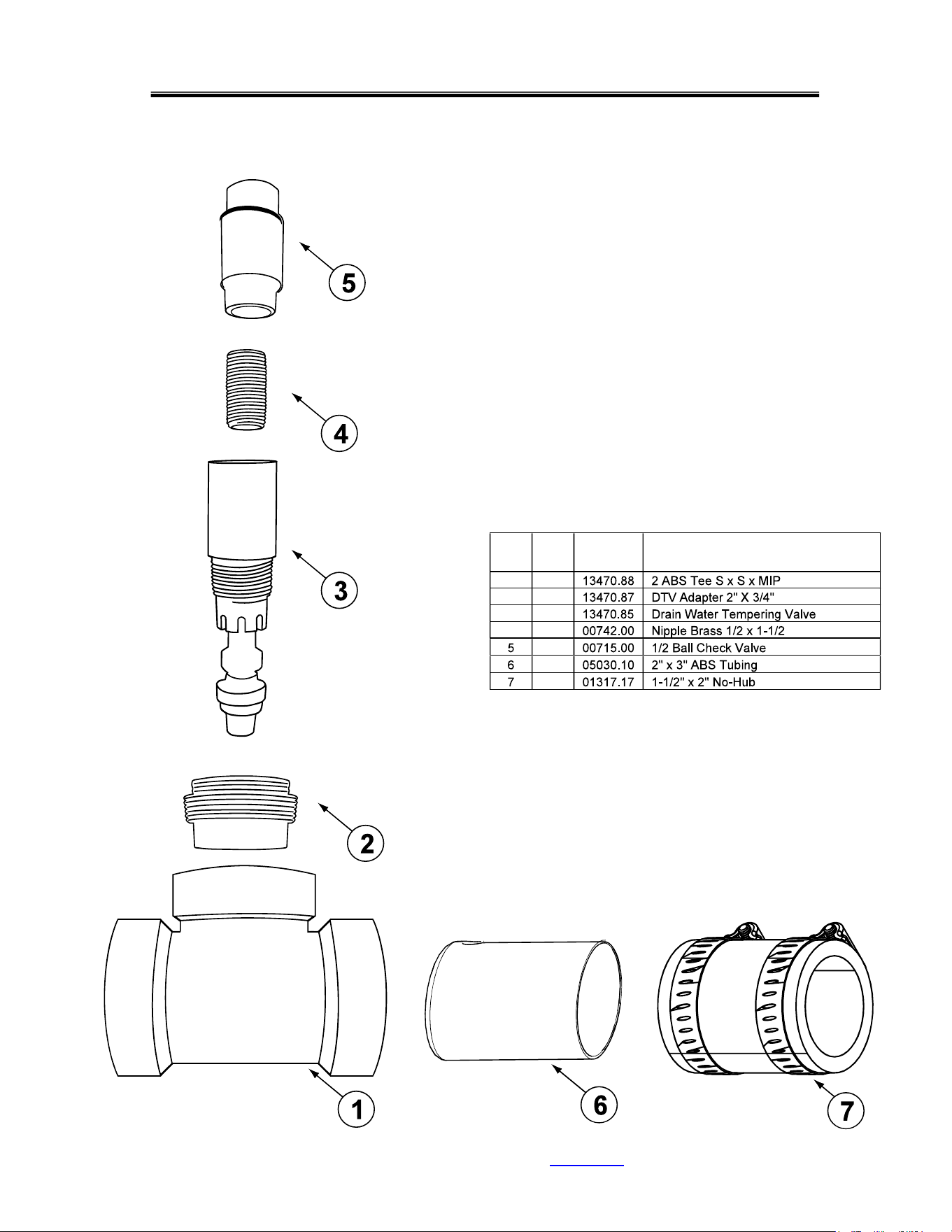
Parts Manual
Buy Parts
Page 22a
ITEM
NO.
NO.
REQ’D
P/N DESCRIPTION
1 1
2 1
3 1
4 1
1
1
1
MODEL EST-66 Installation and Operation Manual Rev.1.04A
Drain Water Tempering Valve Assembly (Effective 03-2023)
PN13475.03 Factory Installed Kit
PN13476.03 Field Installed Kit
Operation
MODEL EST-66 Installation and Operation Manual Rev.1.04A Page
24
5. Electrical Diagram For E-Temp Heater Only
Page 27
6. ELECTRICAL DIAGRAM
D
O
O
R
S
A
F
E
T
Y
S
W
I
T
C
H
D
O
O
R
S
A
F
E
T
Y
S
W
I
T
C
H
T
1
L
1
L
3
T
3
T
1
T
2
L
1
L
2
L
3
T
3
T
1
T
2
L
1
L
2
L
3
T
3
M
A
I
N
C
O
N
T
A
C
T
O
R
T
1
T
2
T
3
L
1
L
2
L
3
L
3
L
2
L
1
T
3
T
2
T
1
1
1
A
2
A
A
2
C
Y
C
L
E
S
T
A
R
T
T
R
I
P
S
W
I
T
C
H
P
O
W
E
R
S
W
I
T
C
H
3 2
7
A
U
T
O
M
A
N
U
A
L
F
I
N
A
L
R
I
N
S
E
T
R
I
P
S
W
I
T
C
H
W
A
T
E
R
S
O
L
E
N
O
I
D
V
A
L
V
E
R
I
N
S
E
W
A
T
E
R
S
O
L
E
N
O
I
D
V
A
L
V
E
N
O
T
E
1
N
O
T
E
2
,
3
N
O
T
E
4
,
&
5
220V
SIG
N
A
L
F
O
R
F
A
N
M
OT
OR
C
ON
T
R
O
L
C
ON
T
A
C
T
OR
COIL
.
CMA KIT PN13578.00
3
A
M
P
S
L
O
W
B
L
O
W
F
U
S
E
(
x
2
)
G
R
O
U
N
D
A
2
A
A
T
1
T
2
L
1
L
2
L
3
T
3
1
1
2
3
6
T
A
N
K
H
E
A
T
E
R
3
k
W
L
2
T
2
A
1
A
2
(
2
3
0
VAC
s
i
n
g
l
e
-
p
h
a
s
e
,
d
u
a
l
f
l
o
a
t
s
)
07/2023
Rev.
1
.
0
3
WASH HEATER
CONTACTOR
WASH PUMP
CONTACTOR
CONVEYOR
CONTACTOR
CONVEYOR
TIMER
T
1
L
1
L
3
T
3
RINSE HEATER
CONTACTOR
RINSE PUMP
CONTACTOR
L
2
T
2
WASH PUMP
CONTACTOR
P
U
M
P
M
O
T
O
R
P
U
M
P
M
O
T
O
R
RINSE
THERMOSTAT
WASH
THERMOSTAT
PRE-WASH
TANK
WASH
TANK
PRE-RINSE
TANK
CHEMICAL
DISPENSER
208-230V
N
O
T
E
S
:
1
:
T
A
B
L
E
L
I
M
I
T
S
W
I
T
C
H
C
O
N
N
E
C
T
I
O
N
P
R
E
-
W
I
R
E
D
A
T
F
A
C
T
O
R
Y
.
2
:
S
A
N
I
/
R
I
N
S
E
.
S
I
G
N
A
L
I
S
O
N
W
H
E
N
F
I
N
A
L
R
I
N
S
E
I
S
A
C
T
I
V
E
.
3
:
C
O
N
N
E
C
T
O
N
L
Y
T
O
P
R
I
M
A
R
Y
O
F
L
I
S
T
E
D
C
L
A
S
S
2
T
R
A
N
S
F
O
R
M
E
R
2
0
8
-
2
3
0
V
6
0
H
z
M
A
X
I
M
U
M
1
0
0
V
A
.
4
:
D
E
T
E
R
G
E
N
T
F
E
E
D
E
R
S
I
G
N
A
L
A
N
D
F
A
N
M
O
T
O
R
C
O
N
T
R
O
L
C
O
N
T
A
C
T
O
R
C
O
I
L
.
5
:
C
O
M
B
I
N
E
D
L
O
A
D
O
F
U
S
E
R
D
E
V
I
C
E
S
(
C
H
E
M
I
C
A
L
P
U
M
P
S
,
F
A
N
C
O
N
T
R
O
L
S
,
E
T
C
.
)
M
U
S
T
N
O
T
E
X
C
E
E
D
1
A
M
P
.
6
:
D
I
S
P
E
N
S
E
R
P
O
W
E
R
B
L
O
C
K
2
0
8
-
2
4
0
V
O
L
T
S
N
O
T
E
6
P
U
M
P
M
O
T
O
R
T1
T2
T3
OVERLOAD
RELAY
95
C
O
N
V
M
O
T
O
R
MODEL EST-66 Installation and Operation Manual Rev.1.04A