Owner's Manual
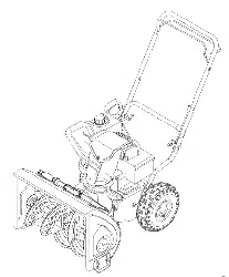
5 Horse Power
22" Two-Stage
Snow Thrower
Model No.
247.887001
CAUTION: Before
using this product,
read this manual and
follow all safety rules
and operating
instructions.
Safety
Assembly
Operation
Service
Maintenance
Espa5ol, p.29
Sears, Roebuck And Co., Hoffman Estates, IL 60179, U.S.A.
Visit our website: www.sears.com/craftsman FORM NO. 769-00750C
Printed in U.S.A. (7/30/2004)
Content Page
Warranty Information .................................... 2
Safe Operation Practices .............................. 3
Assembly ...................................................... 5
Operation ...................................................... 7
Maintenance ................................................. 11
Content Page
Service & Adjustment ....................................... 13
Off-Season Storage ......................................... 15
Trouble-Shooting ............................................. 16
Parts List ......................................................... 18
Espan51 ......................................................... 29
Two -Year Warranty on Craftsman Snow Thrower
For two years from the date of purchase, when this Craftsman Snow Thrower is maintained, lubricated and tuned up according to the instruc-
tions in the owner's manual, Sears will repair, free of charge, any defect in material and workmanship.
If this Craftsman snow thrower is used for commercial or rental purposes, this warranty applies for only 30 days from the date of purchase.
This warranty does not cover:
Expendable items which become worn during normal use, such as skid shoes, shave plate and spark plugs.
Repairs necessary because of operator abuse or negligence, including bent crankshafts and the failure to maintain the equipment
according to the instructions contained in the owner's manual.
WARRANTY SERVICE IS AVAILABLE BY RETURNING THE CRAFTSMAN SNOW THROWER TO THE NEAREST SEARS PARTS & REPAIR
CENTER IN THE UNITED STATES.
This warranty applies only while this product is in use in the United States.
This warranty gives you specific legal rights and you may also have other rights which may vary from state to state.
SEARS, ROEBUCK AND CO., D/817WA, HOFFMAN ESTATES, IL 60179
Repair Protection Agreements
Congratulations on making a smart purchase.Your new Craftsman®
product is designed and manufactured for years of dependable
operation. But like all products, it may require repair from time to
time. That's when having a Repair Protection Agreement can save
you money and aggravation.
Here's what's included in the Agreement:
Expert service by our 12,000 professional repair
_t specialists
Unlimited service and no charge for parts and labor on
all covered repairs
Product replacement if your covered product can't be
@P fixed
Discount of 10% from regular price of service and service-
related parts not covered by the agreement; also, 10% off
regular price of preventive maintenance check
Fast help by phone - phone support from a Sears
technician on products requiring in-home repair, plus
convenient repair scheduling
Purchase a Repair Protection Agreement now and protect yourself
from unexpected hassle and expense.
Once you purchase the Agreement, a simple phone call is all that it
takes for you to schedule service. You can call anytime day or night,
or schedule a service appointment online. Sears has over 12,000
professional repair specialists, who have access to over 4.5 million
quality parts and accessories. That's the kind of professionalism you
can count on to help prolong the life of your new purchase for years
to come. Purchase your Repair Protection Agreement today!
Some limitations and exclusions apply. For prices and additional
information call 1-800-827-6655.
Sears Installation Service
For Sears professional installation of home appliances, garage door
openers, water heaters, and other major home items, inthe U.S.A.
call 1-800-4-MY-HOME®.
Horsepower: 5
Engine Oil: SAE 5W30 Capacity: 21 oz.
Fuel: Unleaded Regular Capacity:
Spark Plug: RJ19LM
Eng ne: Craftsman Eng ne Mode 143.045003
Model Number ...........................................................
Serial Number ...........................................................
Date of Purchase ......................................................
Record both serial number and date of purchase and keep in a
safe place for future reference.
_, ARNING: This symbol points out important safety instructions which, if not followed, could endangerthe personal safety and/or property of yourself and others. Read and follow all instructions in this manual
before attempting to operate this machine. Failure to comply with these instructions may result in personal
injury. When you see this symbol--heed its warning.
_L ARNING: Engine Exhaust, some of its constituents, and certain vehicle components contain or emitchemicals known to State of California to cause cancer and birth defects or other reproductive harm.
DANGER: This machine was built to be operated according to the rules for safe operation in this manual. As with
any type of power equipment, carelessness or error on the part of the operator can result in serious injury. This
machine is capable of amputating hands and feet and throwing objects. Failure to observe the following safety
instructions could result in serious injury or death.
Training
1. Read, understand, and follow ail instructions on the
machine and in the manual(s) before attempting to
assemble and operate. Keep this manual in a safe place
for future and regular reference and for ordering
replacement parts.
2. Be familiar with all controls and their proper operation.
Know how to stop the machine and disengage these
controls quickly.
3. Never allow children under 14 years old to operate this
machine. Those 14 years old and over should read and
understand the operation instructions and safety rules in
this manual and be trained and supervised by a parent in
order to operate this equipment.
4. Never allow adults to operate this machine without proper
instruction.
5. Thrown objects can cause serious personal injury. Plan
your snow throwing pattern to avoid discharge of material
toward roads, bystanders and the like.
6. Keep bystanders, helpers, pets and children at least 75
feet from the machine while it is in operation. Stop
machine if anyone enters the area.
7. Exercise caution to avoid slipping or falling, especially
when backing up.
Preparation
1. Thoroughly inspect the area where the equipment is to be
used. Remove all door mats, newspapers, sleds, boards,
wires and other foreign objects which could be tripped
over or thrown by the auger/impeller.
2. Always wear safety glasses or eye shields during
operation and while performing an adjustment or repair to
protect your eyes. Thrown objects which ricochet can
cause serious injury to the eyes.
3. Do not operate without wearing adequate winter outer
garments. Do not wear jewelry, long scarves or other
loose clothing which could become entangled in moving
parts. Wear footwear which will improve footing on
slippery surfaces.
4. Use a grounded three wire extension cord and receptacle
for all units with electric start engines.
5. Adjust collector housing height to clear gravel or crushed
rock surfaces.
6. Disengage all control levers before starting the engine.
8.
9.
Never attempt to make any adjustments while engine is
running, except where specifically recommended in the
operator's manual.
Let engine and machine adjust to outdoor temperature
before starting to clear snow.
To avoid personal injury or property damage use extreme
care in handling gasoline. Gasoline is extremely
flammable and the vapors are explosive. Serious
personal injury can occur when gasoline is spilled on
yourself or your clothes which can ignite. Wash your skin
and change clothes immediately.
a. Use only an approved gasoline container.
b. Extinguish all cigarettes, cigars, pipes and other
sources of ignition.
c. Never fuel machine indoors.
d. Never remove gas cap or add fuel while the
engine is hot or running.
e. Allow engine to cool at least two minutes before
refueling.
f. Never over-fill fuel tank. Fill tank to no more than
1/zinch below bottom of filler neck to provide space
for fuel expansion.
g. Replace gasoline cap and tighten securely.
h. If gasoline is spilled, wipe it off the engine and
equipment. Move machine to another area. Wait 5
minutes before starting the engine.
i. Never store the machine or fuel container inside
where there is an open flame, spark or pilot light
(e.g. furnace, water heater, space heater, clothes
dryer etc.).
j. Allow machine to cool at least 5 minutes before
storing.
Operation
1. Do not put hands or feet near rotating parts, in the auger/
impeller housing or chute assembly. Contact with the
rotating parts can amputate hands and feet.
2. The auger/impeller control lever is a safety device. Never
bypass its operation. Doing so makes the machine
unsafe and may cause personal injury.
3. The control levers must operate easily in both directions
and automatically return to the disengaged position when
released.
4. Never operate with a missing or damaged chute
assembly. Keep all safety devices in place and working.
5. Neverrunanengineindoorsorinapoorlyventilated
area.Engineexhaustcontainscarbonmonoxide,an
odorlessanddeadlygas.
6. Donotoperatemachinewhileundertheinfluenceof
alcoholordrugs.
7. Mufflerandenginebecomehotandcancauseaburn.Do
nottouch.
8. Exerciseextremecautionwhenoperatingonorcrossing
gravelsurfaces.Stayalertforhiddenhazardsortraffic.
9. Exercisecautionwhenchangingdirectionandwhile
operatingonslopes.
10.Planyoursnowthrowingpatterntoavoiddischarge
towardswindows,walls,carsetc.Toavoidproperty
damageorpersonalinjurycausedbyaricochet.
11.Neverdirectdischargeatchildren,bystandersandpets
orallowanyoneinfrontofthemachine.
12.Donotoverloadmachinecapacitybyattemptingtoclear
snowattoofastofarate.
13.Neveroperatethismachinewithoutgoodvisibilityor
light.Alwaysbesureofyourfootingandkeepafirmhold
onthehandles.Walk,neverrun.
14.Disengagepowertotheauger/impellerwhen
transportingornetinuse.
15.Neveroperatemachineathightransportspeedson
slipperysurfaces.Lookdownandbehindandusecareif
youarebackingup.
16.Ifthemachineshouldstarttovibrateabnormally,stopthe
engine,disconnectthesparkplugandgrounditagainst
theengine.Inspectthoroughlyfordamage.Repairany
damagebeforestartingandoperating.
17.Disengageallcontrolleversandstopenginebeforeyou
leavetheoperatingposition(behindthehandles).Wait
untiltheauger/impellercomestoacompletestopbefore
uncloggingthechuteassembly,makinganyadjustments,
orinspections.
18.Neverputyourhandinthedischargeorcollector
openings.Alwaysusetheclean-outtoolprovidedto
unclogthedischargeopening.Donotunclogchute
assemblywhiletheengineisrunning.
19.Useonlyattachmentsandaccessoriesapprovedbythe
manufacturer(e.g.wheelweights,tirechains,cabsetc.).
20.Ifsituationsoccurwhicharenotcoveredinthismanual,
usecareandgoodjudgment.ContactyournearestSears
storeforassistanceorcallCustomerService.
Maintenance & Storage
1. Never tamper with safety devices. Check their proper
operation regularly.
2. Disengage all bails and stop engine. Wait until the auger/
impeller come to a complete stop. Disconnect the spark
plug wire and ground against the engine to prevent
unintended starting before cleaning, repairing, or
inspecting.
3. Check bolts, and screws for proper tightness at frequent
intervals to keep the machine in safe working condition.
Also, visually inspect machine for any damage.
4. Do not change the engine governor setting or over-speed
the engine. The governor controls the maximum safe
operating speed of the engine.
5. Snow thrower shave plates and skid shoes are subject to
wear and damage. For your safety protection, frequently
check all components and replace with original
equipment manufacturer's (O.E.M.) parts only. "Use of
parts which do not meet the original equipment
specifications may lead to improper performance and
compromise safety!"
6. Check all controls periodically to verify they engage and
disengage properly and adjust, if necessary. Refer to the
adjustment section in this operator's manual for
instructions.
7. Maintain or replace safety and instruction labels, as
necessary.
8. Observe proper disposal laws and regulations for gas,
oil, etc. to protect the environment.
9. Prior to storing, run machine a few minutes to clear snow
from machine and prevent freeze up of auger/impeller.
10. Never store the machine or fuel container inside where
there is an open flame, spark or pilot light such as a water
heater, furnace, clothes dryer etc.
11. Always refer to the operator's manual for proper
instructions on off-season storage.
Your Responsibility
Restrict the use of this power equipment to persons who read,
understand and follow warnings and instructions in this
manual and on the machine.
Do not modify engine
To avoid serious injury or death, do not modify engine in any
way. Tampering with the governor setting can lead to a
runaway engine and cause it to operate at unsafe speeds.
Never tamper with factory setting of engine governor.
Notice regarding Emissions
Engines which are certified to comply with California and
federal EPA emission regulations for SORE (Small Off Road
Equipment) are certified to operate on regular unleaded
gasoline, and may include the following emission control
systems: Engine Modification (EM) and Three Way Catalyst
(TWC) if so equipped.
IMPORTANT: This unit is shipped with the engine full
of oil. After assembly, see page 8 for fuel and oil fill-up
details.
Removing From Carton
1. Cut the corners of the carton and lay the sides flat
on the ground. Remove all packing inserts.
2. Move the snow thrower out of the carton.
3. Make certain the carton has been completely
emptied before discarding it.
Before Assembly
NOTE: Reference to right, left, front or rear of the unit is
from the operating position unless otherwise stated.
• Cut and remove cable ties holding upper handle to
chute assembly.
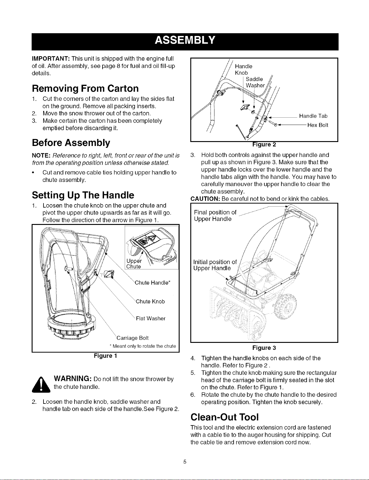
Setting Up The Handle
1. Loosen the chute knob on the upper chute and
pivot the upper chute upwards as far as it will go.
Follow the direction of the arrow in Figure 1.
Flat Washer
'Carriage Bolt
* Meant onlyto rotate the chute
Figure 1
_ ARNING: Do not lift the snow thrower by
the chute handle.
2. Loosen the handle knob, saddle washer and
handle tab on each side of the handle.See Figure 2.
Knob
Handle Tab
%_o- Hex Bolt
Figure 2
3. Hold both controls against the upper handle and
pull up as shown in Figure 3. Make sure that the
upper handle locks over the lower handle and the
handle tabs align with the handle. You may have to
carefully maneuver the upper handle to clear the
chute assembly.
CAUTION: Be careful not to bend or kink the cables.
J
J
Final position of/_
Upper Handle
Initial position of
Upper Handle
Figure 3
4. Tighten the handle knobs on each side of the
handle. Refer to Figure 2.
5. Tighten the chute knob making sure the rectangular
head of the carriage bolt is firmly seated in the slot
on the chute. Refer to Figure 1.
6. Rotate the chute by the chute handle to the desired
operating position. Tighten the knob securely.
Clean-Out Tool
This tool and the electric extension cord are fastened
with a cable tie to the auger housing for shipping. Cut
the cable tie and remove extension cord now.
Final Adjustments
IMPORTANT:Check the adjustments as instructed and
make any final adjustments necessary before operating
the unit. Check all nuts and bolts for tightness.Failure to
follow these instructions may cause damage to unit.
Tire Pressure (Pneumatic Tires)
The tires are over-inflated for shipping purposes. Check
tire pressure and reduce pressure, if needed, to 10-15
psi. Maintain equal pressure on both wheels of the
snow throwe r.
_ WARNING: Maximum tire pressure underany circumstance is 15 psi. Equal tire pressure
should be maintained at all times. Excessive
pressure (over 15 psi) when seating beads
may cause tire/rim assembly to burst with force
sufficient to cause serious injury
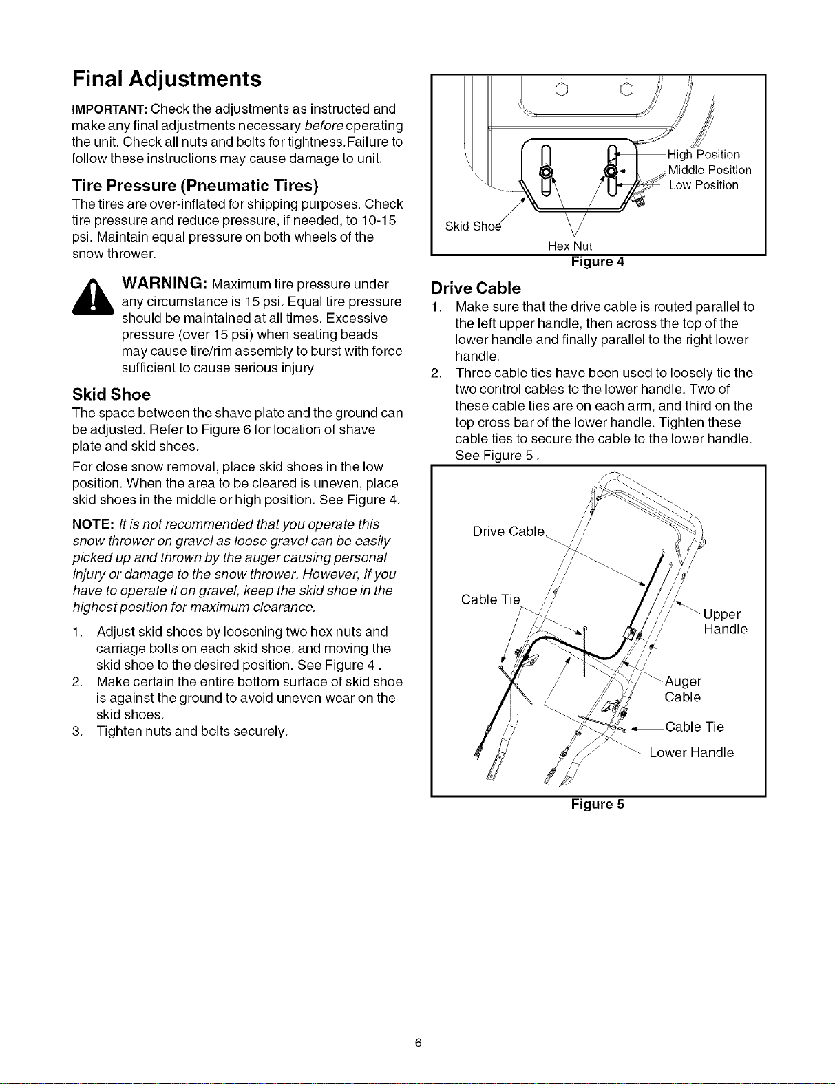
Skid Shoe
The space between the shave plate and the ground can
be adjusted. Refer to Figure 6 for location of shave
plate and skid shoes.
For close snow removal, place skid shoes in the low
position. When the area to be cleared is uneven, place
skid shoes in the middle or high position. See Figure 4.
NOTE: It is not recommended that you operate this
snow thrower on gravel as loose gravel can be easily
picked up and thrown by the auger causing personal
injury or damage to the snow thrower. However, if you
have to operate it on gravel, keep the skid shoe in the
highest position for maximum clearance.
1. Adjust skid shoes by loosening two hex nuts and
carriage bolts on each skid shoe, and moving the
skid shoe to the desired position. See Figure 4.
2. Make certain the entire bottom surface of skid shoe
is against the ground to avoid uneven wear on the
skid shoes.
3. Tighten nuts and bolts securely.
o o
Position
Middle Position
Low Position
Skid
Hex Nut
Figure 4
Drive Cable
1. Make sure that the drive cable is routed parallel to
the left upper handle, then across the top of the
lower handle and finally parallel to the right lower
handle.
2. Three cable ties have been used to loosely tie the
two control cables to the lower handle. Two of
these cable ties are on each arm, and third on the
top cross bar of the lower handle. Tighten these
cable ties to secure the cable to the lower handle.
See Figure 5.
Drive Cable_
Cable Tie
Handle
_Auger
Cable
•,Cable Tie
Lower Handle
Figure 5
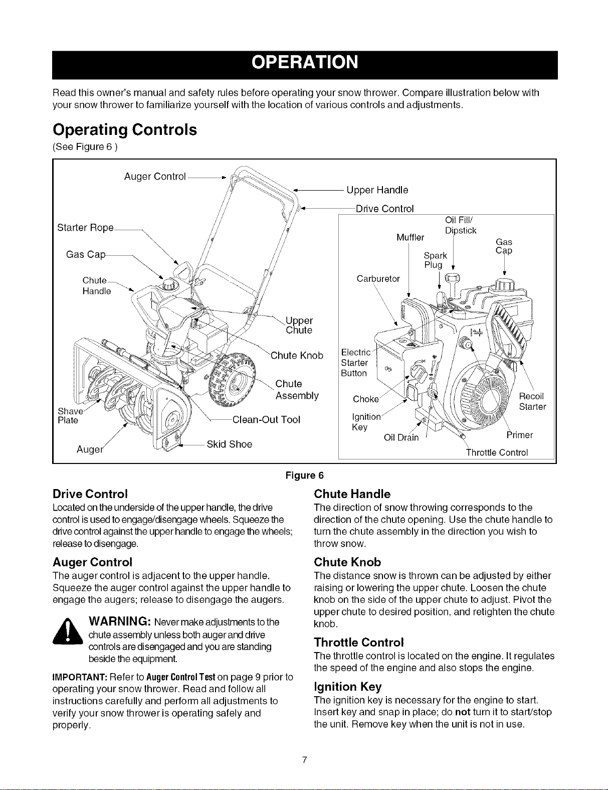
Read this owner's manual and safety rules before operating your snow thrower. Compare illustration below with
your snow thrower to familiarize yourself with the location of various controls and adjustments.
Operating Controls
(See Figure 6 )
Auger Control
Starter Rope_
\
Chute
Upper Handle
Drive Control
Oil Fill/
M" Dipstick
UTHer I
Spark |
Plug _.
Carburetor
Gas
°ip
\.
\\
\
\
\
Knob
ShE
Plate
Auger _
Chute
Assembly
Clean-Out Tool
Shoe
Choke /
Ignition _
Keg
Oil Drain
Recoil
Starter
\
\
Primer
Throttle Control
Figure 6
Drive Control
Located on the underside ofthe upper handle, thedrive
control is usedto engage/disengage wheels. Squeeze the
drivecontrol against the upper handle to engage thewheels;
releaseto disengage.
Chute Handle
The direction of snow throwing corresponds to the
direction of the chute opening. Use the chute handle to
turn the chute assembly in the direction you wish to
throw snow.
Auger Control
The auger control is adjacent to the upper handle.
Squeeze the auger control against the upper handle to
engage the augers; release to disengage the augers.
WAR NING: Never make adjustments tothe
chute assembly unless bothauger and drive
controls are disengaged and you are standing
beside the equipment.
IMPORTANT:Refer to AugerControlTeston page 9 prior to
operating your snow thrower. Read and follow all
instructions carefully and perform all adjustments to
verify your snow thrower is operating safely and
properly.
Chute Knob
The distance snow is thrown can be adjusted by either
raising or lowering the upper chute. Loosen the chute
knob on the side of the upper chute to adjust. Pivot the
upper chute to desired position, and retighten the chute
knob.
Throttle Control
The throttle control is located on the engine. It regulates
the speed of the engine and also stops the engine.
Ignition Key
The ignition key is necessary for the engine to start.
Insert key and snap in place; do not turn it to start/stop
the unit. Remove key when the unit is not in use.
Skid Shoe
The space between the shave plate and the ground can
be adjusted. For close snow removal, place skid shoes
in the low position. Use middle or high position when
area to be cleared is uneven or on gravel surfaces.
Before Starting Engine
Engine Oil
The unit is shipped with oil in engine. Follow the steps
below before starting engine each time.
1. Remove the dipstick from the oil fill. For location of
the oil fill, see Figure 6.
2. Check and make sure that the level of oil is up to
the FULL mark on the dipstick.
3. If the oil level is not up to FULL, pour fresh oil slowly
through the plug. Replace dipstick and check oil
level again.
Gasoline
_ ARNING: Since gasoline is flammable,use caution when handling or storing it. Do not
fill fuel tank while the engine is running, when it
is hot or in an enclosed area. Keep your snow
thrower away from any open flame or an
electrical spark and do not smoke during
fueling.
IMPORTANT:Your snow thrower is
equipped with a plastic fuel tank insert for
shipping purposes. Please discard it at
this time.
A. Electric Starter
The snow thrower engine is equipped with a 120 volt
A.C. electric starter and recoil starter. The electric
starter is equipped with a three-wire power cord and
plug and is designed to operate on 120 volt AC
household current.
Cold Start
1. Determine whether your house wiring is a three-
wire grounded system. Ask a licensed electrician if
you are not certain.
_ ARNING: The electric starter must beproperly grounded at all times to avoid the
possibility of electric shock to the operator. If
your house wiring system is not a three-wire
grounded system, do not use this electric starter
under any conditions.
2. If your house wiring system is grounded and a
three-hole receptacle is not available at the point
the snow thrower starter will normally be used, one
should be installed by a licensed electrician.
NOTE: When connecting the power cord, always
connect cord to starter on engine first, then plug the
other end into a three-hole grounded 120 Volt
receptacle. When disconnecting the power cord,
always unplug the end from the three-hole, grounded
receptacle first.
3.
4.
• Always use clean, fresh, unleaded
grade automotive gasoline.
• Avoid using alcohol blended fuels which can attract 6.
moisture and damage fuel system if left in tank 7.
during storage. See Off-Season Storage section on 8.
page 15. 9.
CAUTION: Never use engine or carburetor cleaner 10.
products in the fuel tank.
• Fill the fuel tank outdoors and use a funnel or spout 11.
to prevent spilling. The gasoline container should
be clean and free of rust or other foreign particles.
• Never fill the fuel tank completely. Fill the tank to no 12.
more than 1/2 inch below bottom of filler neck to
provide space for expansion of fuel.
• Wipe off any spilled fuel before starting the engine.
To Start Engine
_ ARNING: Be sure no one other than theoperator is standing near the snow thrower
while starting or operating. Do not operate this
snow thrower unless the chute assembly has
been properly installed.
• For location of engine controls, see Figure 6.
Attach spark plug wire to spark plug.
Make sure that the auger control and the drive
control are disengaged.
Remove the keys from the plastic bag. Push key
into the ignition slot. Do not turn the key. Keep
second key in a safe place.
Move the choke knob to FULL choke position.
Move throttle control to the FAST position.
Turn fuel valve on, if so equipped.
Connect power cord to the switch box on engine.
Plug the other end of the power cord into a three-
hole, grounded 120 volt A.C. receptacle.
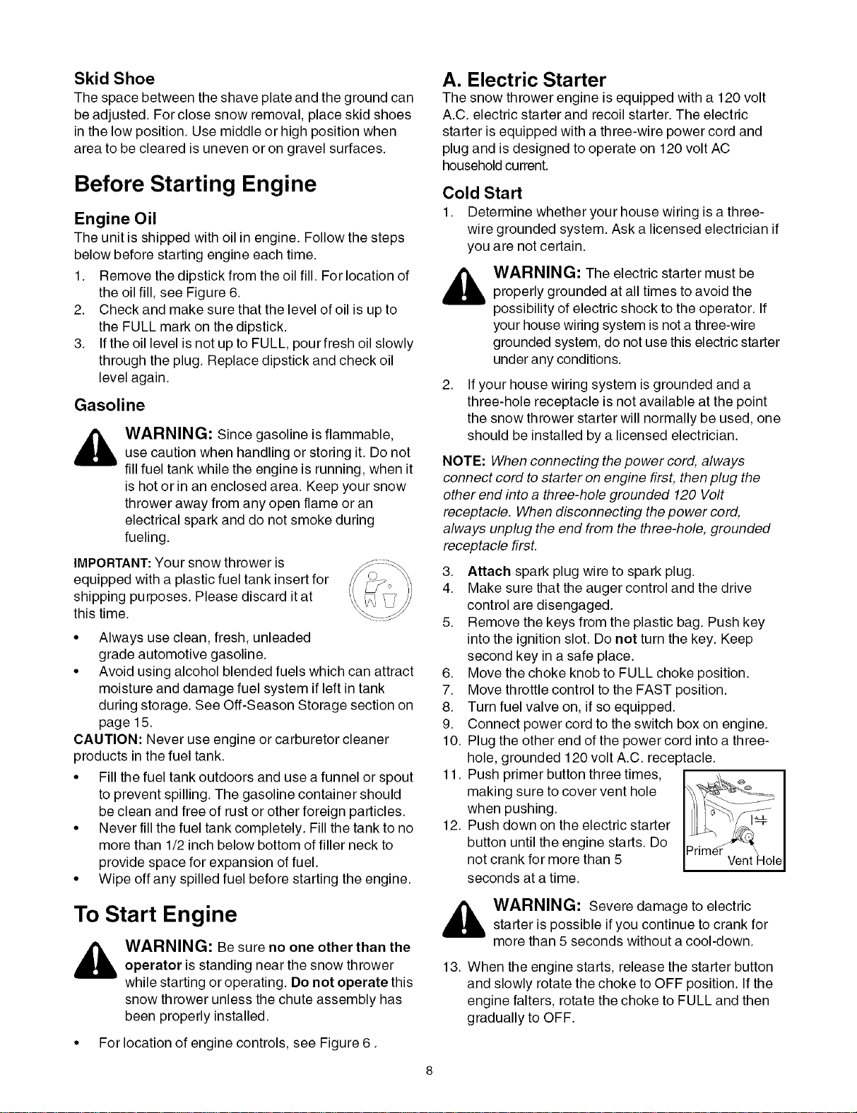
Push primer button three times,
making sure to cover vent hole
when pushing.
Push down on the electric starter
button until the engine starts. Do
not crank for more than 5
seconds at a time.
_ ARNING: Severe damage to electric
starter is possible if you continue to crank for
more than 5 seconds without a cool-down.
13. When the engine starts, release the starter button
and slowly rotate the choke to OFF position. If the
engine falters, rotate the choke to FULL and then
gradually to OFF.
NOTE:When engaging the electric starter, a slight
hesitation of a few seconds may occur before the
engine starts to turn. This is normal and is not harmful
to the engine.
14. Disconnect the power cord from the receptacle first
and then from the switch box on the engine.
15. Allow the engine to warm up for a few minutes
because the engine will not develop full power until
it reaches operating temperature. Operate at FULL
throttle when throwing snow.
NOTE: If the starter motor runs but the engine does not
turn over, the starter gear may have frozen. Place the
snow thrower in a warmer part of the garage till the gear
is free of the accumulated ice.
Warm Start
If restarting a warm engine, rotate choke to OFF
instead of FULL and press the starter button. Do not
push the primer button.
B. Recoil Starter
Make sure that the auger control and the drive control
are released.
Cold Start
1. Move throttle control to FAST position.
2. Turn fuel valve on, if so equipped.
3. Push key into the ignition slot so that it snaps into
place. Do not turn key. Remove plastic bag and
keep the second key in a safe place.
4. Rotate choke control to FULL choke position.
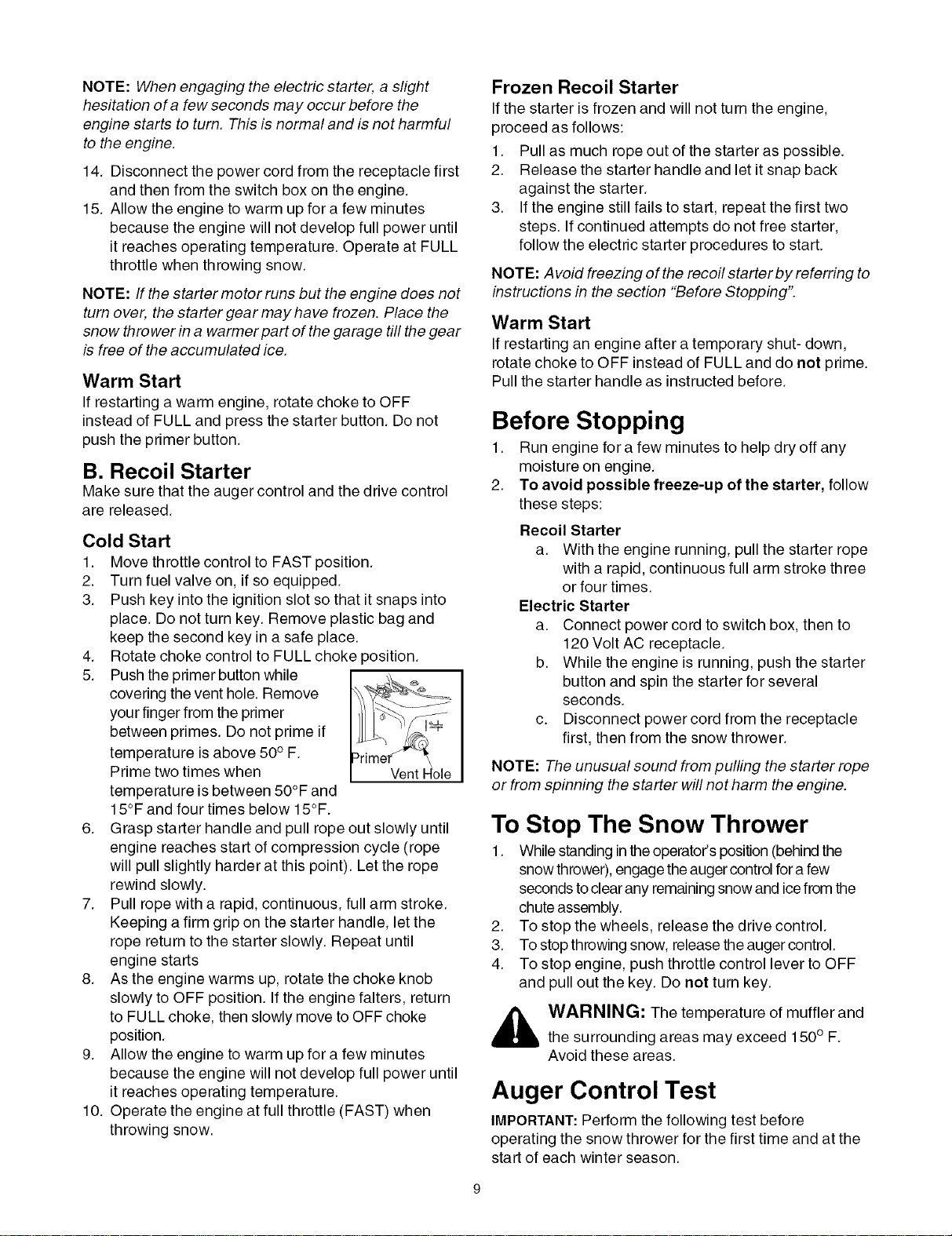
5. Push the primer button while
covering the vent hole. Remove
your finger from the primer
between primes. Do not prime if
temperature is above 50° F.
Prime two times when
temperature is between 50°F and
15°F and four times below 15°F.
6. Grasp starter handle and pull rope out slowly until
engine reaches start of compression cycle (rope
will pull slightly harder at this point). Let the rope
rewind slowly.
7. Pull rope with a rapid, continuous, full arm stroke.
Keeping a firm grip on the starter handle, let the
rope return to the starter slowly. Repeat until
engine starts
8. As the engine warms up, rotate the choke knob
slowly to OFF position. If the engine falters, return
to FULL choke, then slowly move to OFF choke
position.
9. Allow the engine to warm up for a few minutes
because the engine will not develop full power until
it reaches operating temperature.
10. Operate the engine at full throttle (FAST) when
throwing snow.
Frozen Recoil Starter
If the starter is frozen and will not turn the engine,
proceed as follows:
1. Pull as much rope out of the starter as possible.
2. Release the starter handle and let it snap back
against the starter.
3. If the engine still fails to start, repeat the first two
steps. If continued attempts do not free starter,
follow the electric starter procedures to start.
NOTE: Avoid freezing of the recoil starter by referring to
instructions in the section "Before Stopping".
Warm Start
If restarting an engine after a temporary shut- down,
rotate choke to OFF instead of FULL and do not prime.
Pull the starter handle as instructed before.
Before Stopping
1. Run engine for a few minutes to help dry off any
moisture on engine.
2. To avoid possible freeze-up of the starter, follow
these steps:
Recoil Starter
a. With the engine running, pull the starter rope
with a rapid, continuous full arm stroke three
or four times.
Electric Starter
a. Connect power cord to switch box, then to
120 Volt AC receptacle.
b. While the engine is running, push the starter
button and spin the starter for several
seconds.
c. Disconnect power cord from the receptacle
first, then from the snow thrower.
NOTE: The unusual sound from pulling the starter rope
or from spinning the starter will not harm the engine.
To Stop The Snow Thrower
1. While standing inthe operator's position (behind the
snow thrower), engage the auger control fora few
seconds to clear any remaining snow and icefrom the
chute assembly.
2. To stop the wheels, release the drive control.
3. To stop throwing snow, release the auger control.
4. To stop engine, push throttle control lever to OFF
and pull out the key. Do not turn key.
_lb ARNING: The temperature of muffler and
the surrounding areas may exceed 150 ° F.
Avoid these areas.
Auger Control Test
IMPORTANT:Perform the following test before
operating the snow thrower for the first time and at the
start of each winter season.
Checktheadjustmentoftheaugercontrolasfollows:
• Whentheaugercontrolisreleasedandinthe
disengaged"up"position,thecableshouldhave
verylittleslack,butshouldNOTbetight.
,_ WARNING: Do not over-tighten the cable.
Over-tightening may prevent the auger from
disengaging and compromise the safety of the
snow thrower.
• In a well-ventilated area, start the snow thrower
engine as instructed earlier in this section under the
heading StartingEngine.Make sure the throttle is set
in the FAST position.
• While standing in the operator's position (behind
the snow thrower) engage the auger.
• Allow the auger to remain engaged for
approximately ten (10) seconds before releasing
the auger control. Repeat this several times.
• With the engine running in the FAST position and
the auger control in the disengaged "up" position,
walk to the front of the machine.
• Confirm that the auger has completely stopped
rotating and shows NO signs of motion.
IMPORTANT: If the auger shows ANY signs of rotating,
immediately return to the operator's position and shut
off the engine. Wait for all moving parts to stop before
readjusting the auger control cable as shown in the
"Adjustments" on page 14.
Clearing the Snow
CAUTION: Check the area to be cleared for foreign
objects. Remove, if any.
1. Start the engine following Starting instructions.
2. Rotate the chute assembly to the desired direction,
away from bystanders and/or buildings.
3. Making certain no bystanders or obstacles are in
front of the unit, squeeze the auger control
completely against the upper handle to fully engage
the augers.
4. While the auger control is engaged, squeeze the
drive control completely against the upper handle
to engage the wheels.
5. As the snow thrower starts to move, maintain a firm
hold on the handle, and guide the snow thrower
along the path to be cleared.
6. Release the auger and drive controls to stop the
snow throwing action and forward motion.
NOTE: Your unit is equipped with a clutch in the
transmission. If the wheels stop turning while trying to
discharge large volumes of snow, immediately
disengage drive control and allow rotating augers to
discharge snow from the housing. Continue operation
on a narrower stretch with less volume of snow.
Operating Tips
NOTE: Allow the engine to warm up for a few minutes
as the engine will not develop full power until it reaches
operating temperature.
_ ARNING: The temperature of muffler and
surrounding areas may exceed 150° F.Avoid
these areas.
• For most efficient snow removal, remove snow
immediately after it falls.
• Discharge snow downwind whenever possible.
Slightly overlap each previous swath.
• Set the skid shoes 1/4" below the shave plate for
normal usage. The skid shoes may be adjusted
upward for hard-packed snow.
NOTE: It is not recommended that you operate this
snow thrower on gravel as loose gravel can be easily
picked up and thrown by the auger causing personal
injury and/or damage to the snow thrower.
• If for some reason, you have to operate the snow
thrower on gravel, keep the skid shoe in the highest
position for maximum clearance between the
ground and the shave plate.
• Clean the snow thrower thoroughly after each use.
Clean-Out Tool
_ WARNING: Stop engine by moving throttlelever to stop position and wait for ALL moving
parts to stop, before using the clean-out tool.
Theclean-out tool isconveniently fastened tothe rear ofthe
auger housing with a mounting clip.
When snow and ice collect in thechute assembly during
operation, use this tool to safely clean the chute and chute
opening. Follow the steps below to operate it:
1. Release both auger and drive control.
2. Stop the engine by moving throttle lever to stop
position.
3. Remove the clean-out tool from the clip which secures
itto the rear ofthe auger housing.
4. Use the shovel-shaped end ofthe clean-out tool to
dislodge and scoop any snow and ice which has
formed in and near the chute assembly.
_ WARNING: Never use your hands to cleansnow and ice from the chute assembly or auger
housing.
5. Re-fasten the clean-out toolto the mounting clip on the
rearof theauger housing.You can now re-startthe snow
thrower's enginefor more snow cleaning.
7. On each succeeding pass, readjust the chute
assembly to the desired position and slightly
overlap the previously cleared path.
10
General Recommendations
• Always observe safety rules when performing any
maintenance.
• The warranty on this snow thrower does not cover
items that have been subjected to operator abuse
or negligence. To receive full value from the
warranty, operator must maintain the snow
thrower as instructed in this manual.
• Some adjustments will have to be made
periodically to maintain your unit properly.
• All adjustments in the Service and Adjustments
section of this manual should be checked at least
once each season.
• Follow maintenance schedule on this page.
• Periodically check all fasteners and make sure
these are tight.
_ ARNING: Always stop the engine anddisconnect the spark plug wire before
performing any maintenance or adjustments.
Maint. Tasks
Product:
Lubricate pivot points
Check V belts
Engine:
Check engine oil
Change engine oil
Check spark plug
Replace spark plug
Empty fuel system
4
Maintenance Schedule
4
Every 25
hours
operation
4
4
Every
100 hrs.
operation
4
Service Dates
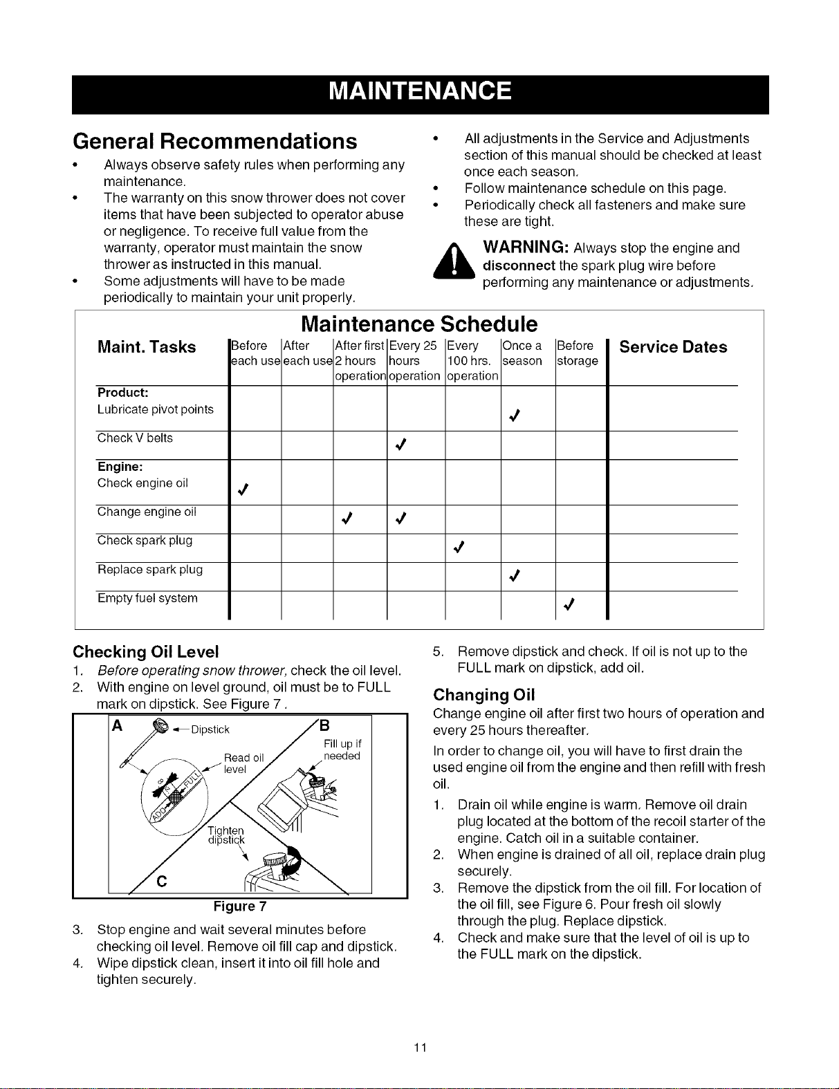
Checking Oil Level
1. Before operating snow thrower, check the oil level.
2. With engine on level ground, oil must be to FULL
mark on dipstick. See Figure 7.
A_"_ Dipstick
Read oil
Figure 7
3. Stop engine and wait several minutes before
checking oil level. Remove oil fill cap and dipstick.
4. Wipe dipstick clean, insert it into oil fill hole and
tighten securely.
5. Remove dipstick and check. If oil is not up to the
FULL mark on dipstick, add oil.
Changing Oil
Change engine oil after first two hours of operation and
every 25 hours thereafter.
In order to change oil, you will have to first drain the
used engine oil from the engine and then refill with fresh
oil.
1. Drain oil while engine is warm. Remove oil drain
plug located at the bottom of the recoil starter of the
engine. Catch oil in a suitable container.
2. When engine is drained of all oil, replace drain plug
securely.
3. Remove the dipstick from the oil fill. For location of
the oil fill, see Figure 6. Pour fresh oil slowly
through the plug. Replace dipstick.
4. Check and make sure that the level of oil is up to
the FULL mark on the dipstick.
11
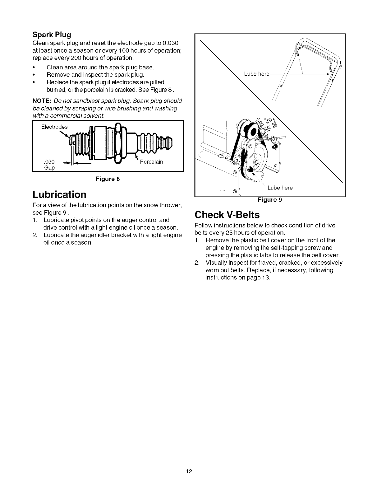
Spark Plug
Clean spark plug and reset the electrode gap to 0.030"
at least once a season or every 100 hours of operation;
replace every 200 hours of operation.
• Clean area around the spark plug base.
• Remove and inspect the spark plug.
• Replace the spark plug if electrodes are pitted,
burned, orthe porcelain is cracked. See Figure 8.
NOTE: Do not sandblast spark plug. Spark plug should
be cleaned by scraping or wire brushing and washing
with a commercial solvent.
Electrodes
.030" Porcelain
Gap
Figure 8
Lubrication
For a view of the lubrication points on the snow thrower,
see Figure 9.
1. Lubricate pivot points on the auger control and
drive control with a light engine oil once a season.
2. Lubricate the auger idler bracket with a light engine
oil once a season
Lube
,Lube here
Figure 9
Check V-Belts
Follow instructions below to check condition of drive
belts every 25 hours of operation.
1. Remove the plastic belt cover on the front of the
engine by removing the self-tapping screw and
pressing the plastic tabs to release the belt cover.
2. Visually inspect for frayed, cracked, or excessively
worn out belts. Replace, if necessary, following
instructions on page 13.
12
WARNING: Always stop the engine of the
snow thrower, disconnect spark plug wire and
move it away from the spark plug before
performing any adjustments or repairs.
WARNING: Never attempt to clean the
chute assembly or make any adjustments while
the engine is running. Always wear safety
glasses during operation or while performing
any adjustments or repairs.
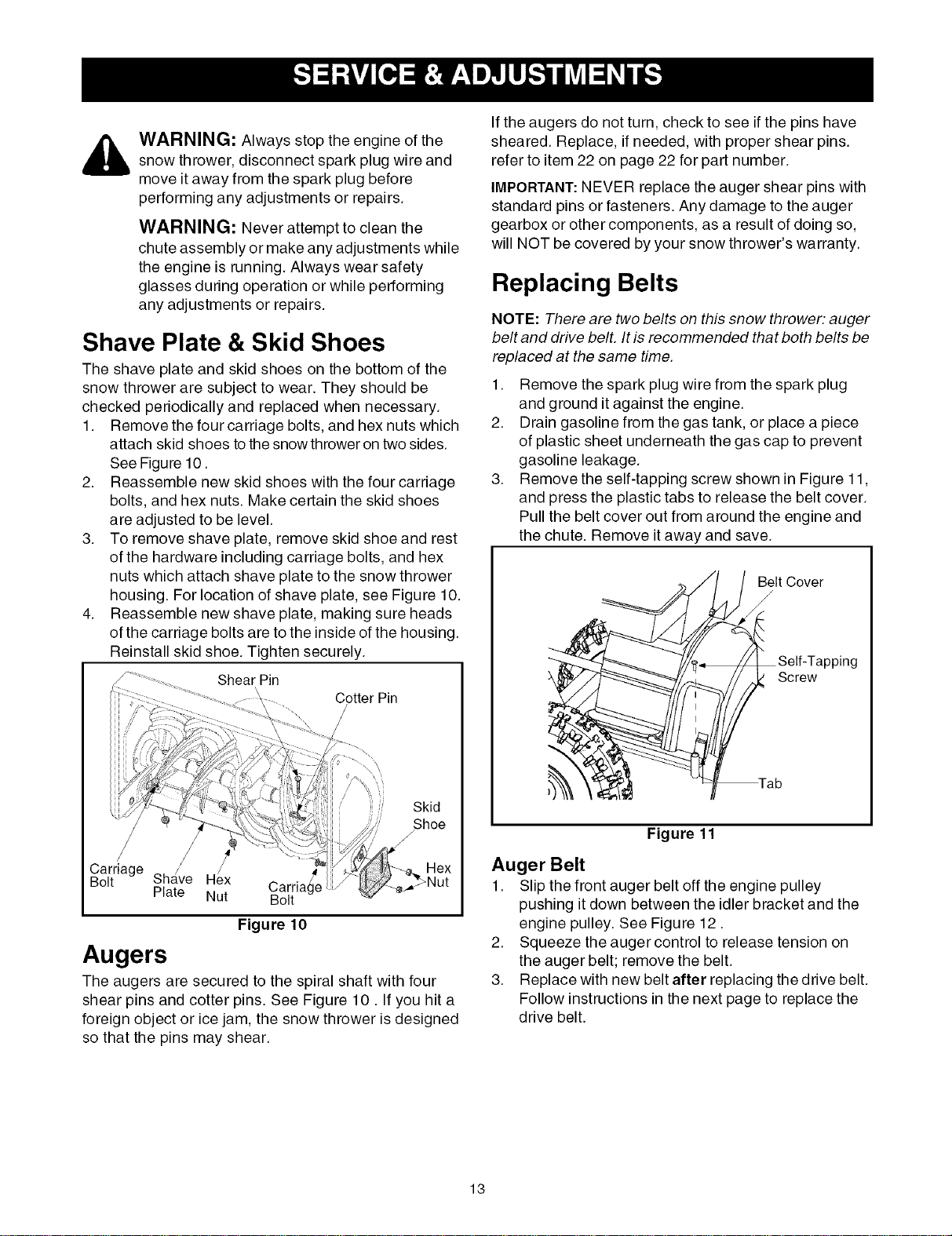
Shave Plate & Skid Shoes
The shave plate and skid shoes on the bottom of the
snow thrower are subject to wear. They should be
checked periodically and replaced when necessary.
1. Remove the four carriage bolts, and hex nuts which
attach skid shoes to the snow thrower on two sides.
See Figure 10.
2. Reassemble new skid shoes with the four carriage
bolts, and hex nuts. Make certain the skid shoes
are adjusted to be level.
3. To remove shave plate, remove skid shoe and rest
of the hardware including carriage bolts, and hex
nuts which attach shave plate to the snow thrower
housing. For location of shave plate, see Figure 10.
4. Reassemble new shave plate, making sure heads
of the carriage bolts are to the inside of the housing.
Reinstall skid shoe. Tighten securely.
Shear Pin
Cotter Pin
Skid
/Shoe
Carriage
Sha/ve Hex Carria _Age
Bolt
Plate Nut Bolt
Figure 10
Augers
The augers are secured to the spiral shaft with four
shear pins and cotter pins. See Figure 10. If you hit a
foreign object or ice jam, the snow thrower is designed
so that the pins may shear.
If the augers do not turn, check to see if the pins have
sheared. Replace, if needed, with proper shear pins.
refer to item 22 on page 22 for part number.
IMPORTANT:NEVER replace the auger shear pins with
standard pins or fasteners. Any damage to the auger
gearbox or other components, as a result of doing so,
will NOT be covered by your snow thrower's warranty.
Replacing Belts
NOTE: There are two belts on this snow thrower: auger
belt and drive bell It is recommended that both belts be
replaced at the same time.
1. Remove the spark plug wire from the spark plug
and ground it against the engine.
2. Drain gasoline from the gas tank, or place a piece
of plastic sheet underneath the gas cap to prevent
gasoline leakage.
3. Remove the self-tapping screw shown in Figure 11,
and press the plastic tabs to release the belt cover.
Pull the belt cover out from around the engine and
the chute. Remove it away and save.
Belt Cover
/
Lpping
Screw
Figure 11
Auger Belt
1. Slip the front auger belt off the engine pulley
pushing it down between the idler bracket and the
engine pulley. See Figure 12.
2. Squeeze the auger control to release tension on
the auger belt; remove the belt.
3. Replace with new belt after replacing the drive belt.
Follow instructions in the next page to replace the
drive belt.
13

Drive Belt
\
\
\
Engine Pulley
Auger Belt
)___Auger Pulley
_ Idler Bracket
Figure 12
Drive Belt
NOTE: Replace the drive belt before reassembling the
new auger belt.
1. Tip the snow thrower up and forward so that it rests
on the auger housing.
2. Remove the spring that connects the transmission
to a bolt on the engine frame. See Figure 13.
\\
\
Spring (shown
removed from
transmission)
iger Pulley
Drive Belt
NOTE:Transmission shown pushed forward
Figure 13
3. Pivot the transmission forward to release pressure
on the drive belt. Remove from transmission pulley.
4. Remove the drive belt from around the engine
pulley, and away from the unit.
5. Place the new drive belt into the groove on the
engine pulley. See Figure 12.
6. Tilt the transmission forward and position the drive
belt on the drive pulley.
7. Reconnect the spring to the bolt on the engine
frame and secure the transmission.
8. Reassemble the belt cover on the snow thrower.
Adjustments
Auger Cable
Periodicadjustment tothe auger control cable may be
required due to normal stretch and wear on thebelt.
Adjustment isneeded iftheaugers seem to hesitatewhile
turning, butthe engine maintainsspeed, orcontinue turning
with theauger control disengaged.
1. Remove the self-tapping screw and press the tabs
that secure the belt cover to the snow thrower
housing. Pull the belt cover from around the engine
and chute and keep it away. You can now access
the auger cable.
2. Tighten two hex nuts on the auger cable towards
the spring to increase the tension on the auger belt.
See Figure 14.
3. Reassemble the belt cover.
4. Start engine and verify auger control engages and
disengages properly.
NOTE: If auger continues to rotate with the control
disengaged, shut off engine and readjust.
Washer ..
BeltCover _-
Nut
Figure 14
Skid Shoe
Refer to page 6 for details.
14
If the snow thrower will not be used for 30 days or
longer, or if it is the end of the snow season when the
last possibility of snow is gone, the equipment needs to
be stored properly. Follow storage instructions below to
ensure top performance from the snow thrower for
many more years.
Preparing Engine
_ ARNING: Never store snow thrower withfuel in tank indoors or in poorly ventilated
areas, where fuel fumes may reach an open
flame, spark or pilot light as on a furnace, water
heater, clothes dryer or gas appliance.
NOTE: It is important toprevent gum deposits from
forming in essential fuel system parts of the engine
such as the carburetor, fuel filter, fuel hose or tank
during storage.
CAUTION: Alcohol blended fuels (called gasohol or
using ethanol or methanol) can attract moisture which
leads to separation and formation of acids during
storage. Acidic gas can damage the fuel system of an
engine while in storage.
To avoid engine problems, the fuel system shouldbe
emptiedbefore storage for 30 days or longer. Follow
these instructions to prepare your snow thrower for
storage:
_ WARNING: Drain fuel into an approved
container outdoors, away from any open flame.
Be certain engine is cool. Do not smoke. Fuel
left in engine during warm weather deteriorates
and will cause serious starting problems.
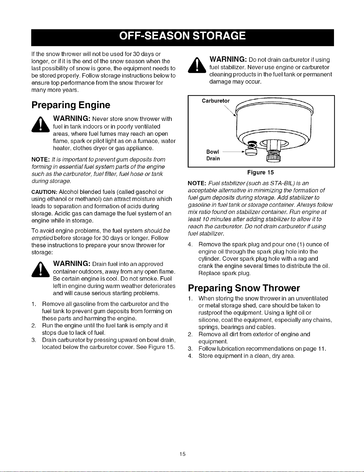
1. Remove all gasoline from the carburetor and the
fuel tank to prevent gum deposits from forming on
these parts and harming the engine.
2. Run the engine until the fuel tank is empty and it
stops due to lack of fuel.
3. Drain carburetor by pressing upward on bowl drain,
located below the carburetor cover. See Figure 15.
_ ARNING: Do not drain carburetor if using
fuel stabilizer. Never use engine or carburetor
cleaning products in the fuel tank or permanent
damage may occur.
Carburet__
Drain
Figure 15
NOTE: Fuel stabilizer (such as STA-BIL) is an
acceptable alternative in minimizing the formation of
fuel gum deposits during storage. Add stabilizer to
gasoline in fuel tank or storage container. Always follow
mix ratio found on stabilizer container. Run engine at
least 10 minutes after adding stabilizer to allow it to
reach the carburetor. Do not drain carburetor if using
fuel stabilizer.
4.
Remove the spark plug and pour one (1) ounce of
engine oil through the spark plug hole into the
cylinder. Cover spark plug hole with a rag and
crank the engine several times to distribute the oil.
Replace spark plug.
Preparing Snow Thrower
1. When storing the snow thrower in an unventilated
or metal storage shed, care should be taken to
rustproof the equipment. Using a light oil or
silicone, coat the equipment, especially any chains,
springs, bearings and cables.
2. Remove all dirt from exterior of engine and
equipment.
3. Follow lubrication recommendations on page 11.
4. Store equipment in a clean, dry area.
15
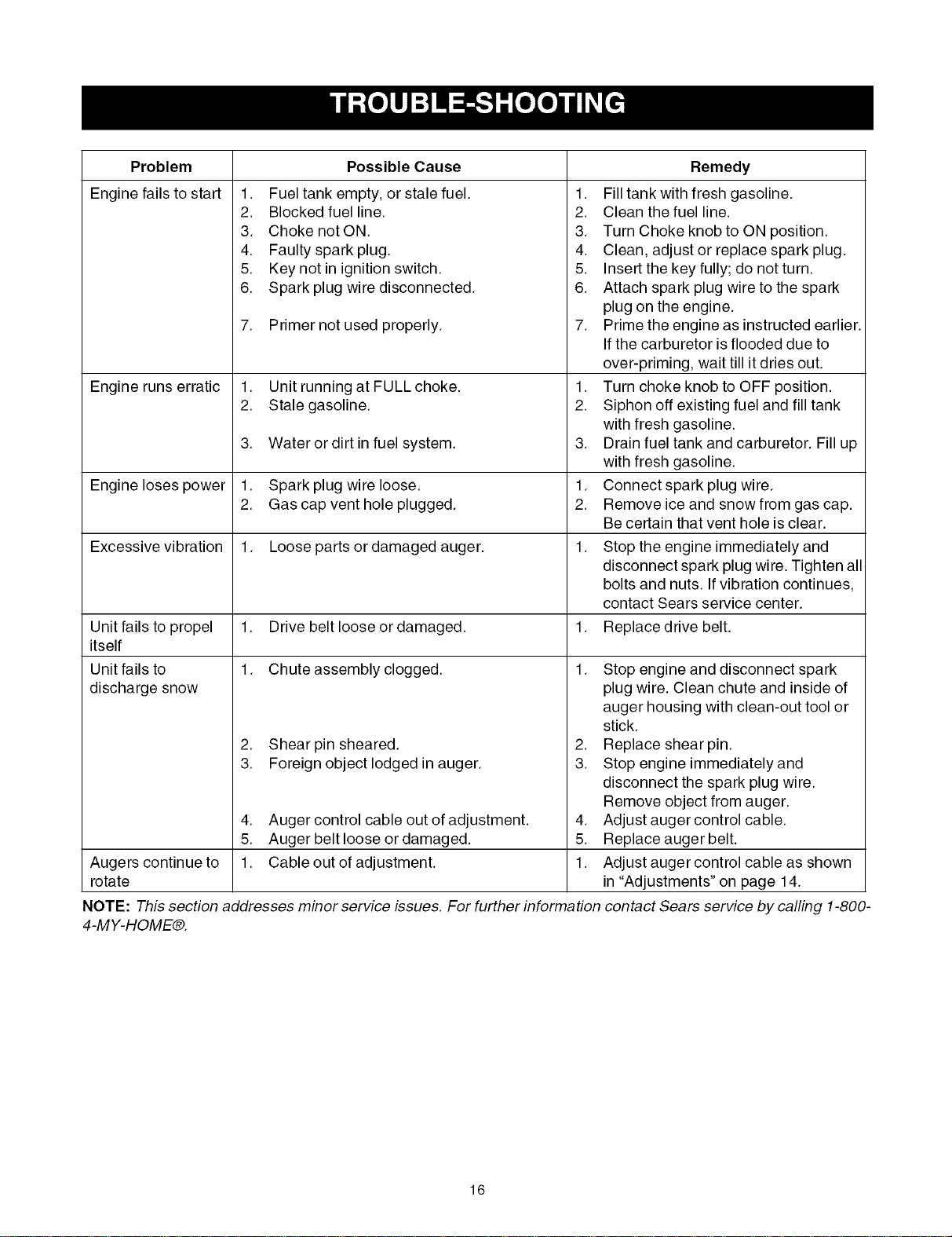
Problem
Engine fails to start 1.
2.
3.
4.
5.
6.
7.
Engine runs erratic 1.
2.
3.
Engine loses power 1.
2.
Excessive vibration 1.
Unit fails to propel 1.
itself
Unit fails to 1.
discharge snow
2.
3.
4.
5.
Augers continue to 1.
rotate
Possible Cause
Fuel tank empty, or stale fuel.
Blocked fuel line.
Choke not ON.
Faulty spark plug.
Key not in ignition switch.
Spark plug wire disconnected.
Primer not used properly.
Unit running at FULL choke.
Stale gasoline.
1.
2.
3.
4.
5.
6.
7.
1.
2.
Water or dirt in fuel system. 3.
Spark plug wire loose. 1.
Gas cap vent hole plugged. 2.
Loose parts or damaged auger. 1.
Drive belt loose or damaged. 1.
Chute assembly clogged. 1.
Shear pin sheared.
Foreign object lodged in auger.
Auger control cable out of adjustment.
Auger belt loose or damaged.
Cable out of adjustment.
2.
3.
Remedy
Fill tank with fresh gasoline.
Clean the fuel line.
Turn Choke knob to ON position.
Clean, adjust or replace spark plug.
Insert the key fully; do not turn.
Attach spark plug wire to the spark
plug on the engine.
Prime the engine as instructed earlier.
If the carburetor is flooded due to
over-priming, wait till it dries out.
Turn choke knob to OFF position.
Siphon off existing fuel and fill tank
with fresh gasoline.
Drain fuel tank and carburetor. Fill up
with fresh gasoline.
Connect spark plug wire.
Remove ice and snow from gas cap.
Be certain that vent hole is clear.
Stop the engine immediately and
disconnect spark plug wire. Tighten all
bolts and nuts. If vibration continues,
contact Sears service center.
Replace drive belt.
4.
5.
1.
NOTE: This section addresses minor service issues. For further information
4-MY-HOME®.
Stop engine and disconnect spark
plug wire. Clean chute and inside of
auger housing with clean-out tool or
stick.
Replace shear pin.
Stop engine immediately and
disconnect the spark plug wire.
Remove object from auger.
Adjust auger control cable.
Replace auger belt.
Adjust auger control cable as shown
in "Adjustments" on page 14.
contact Sears service by calling 1-800-
16
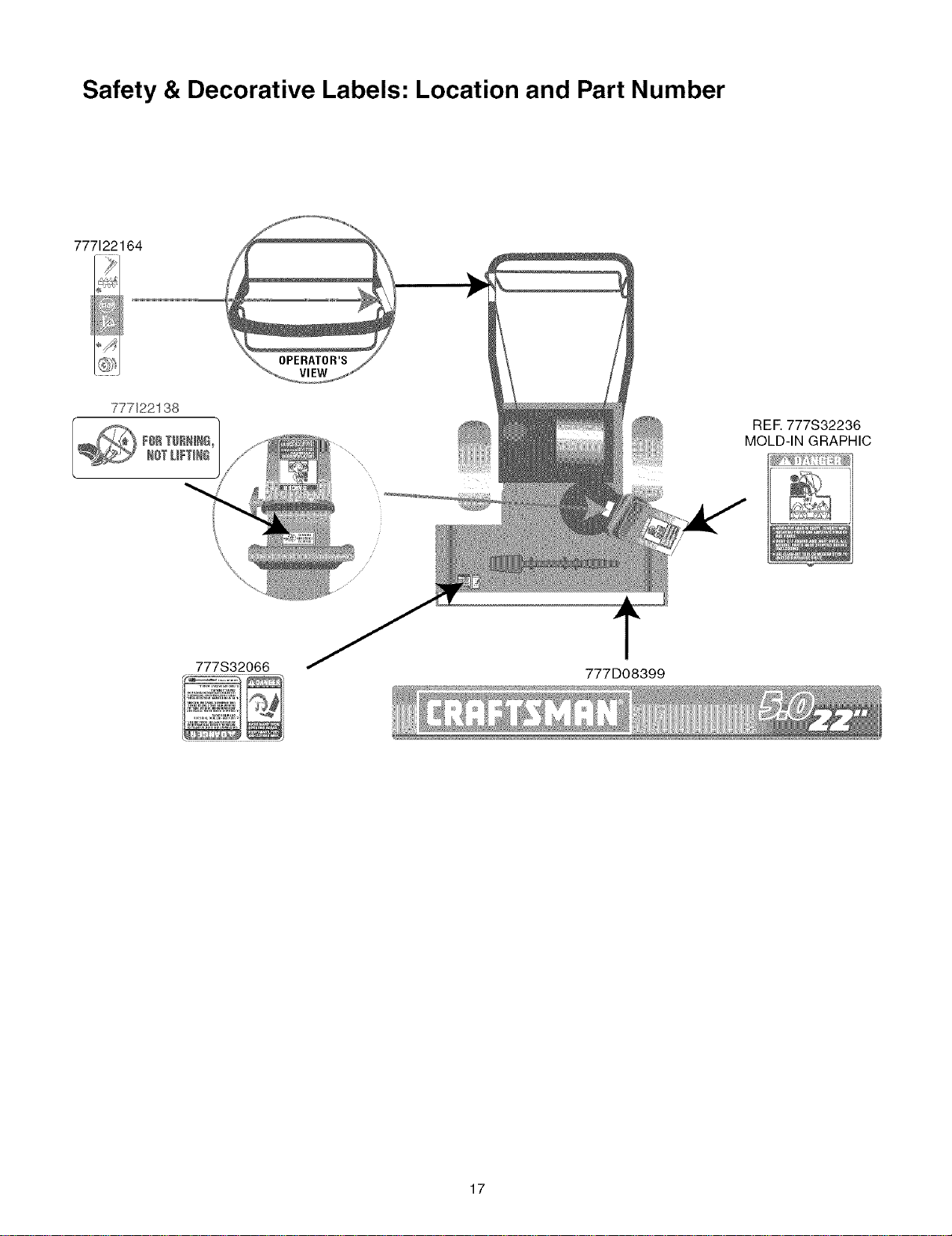
Safety & Decorative Labels: Location and Part Number
777122164
OPERATOR'S
7771221 38
REF. 777S32236
MOLD-IN GRAPHIC
777S32066
777D08399
17
I. 12
14
\\
17
\
26
6
\
\
\
\
\\
\
\
\
25
19
\
\
'27
\
23
22
_29
18
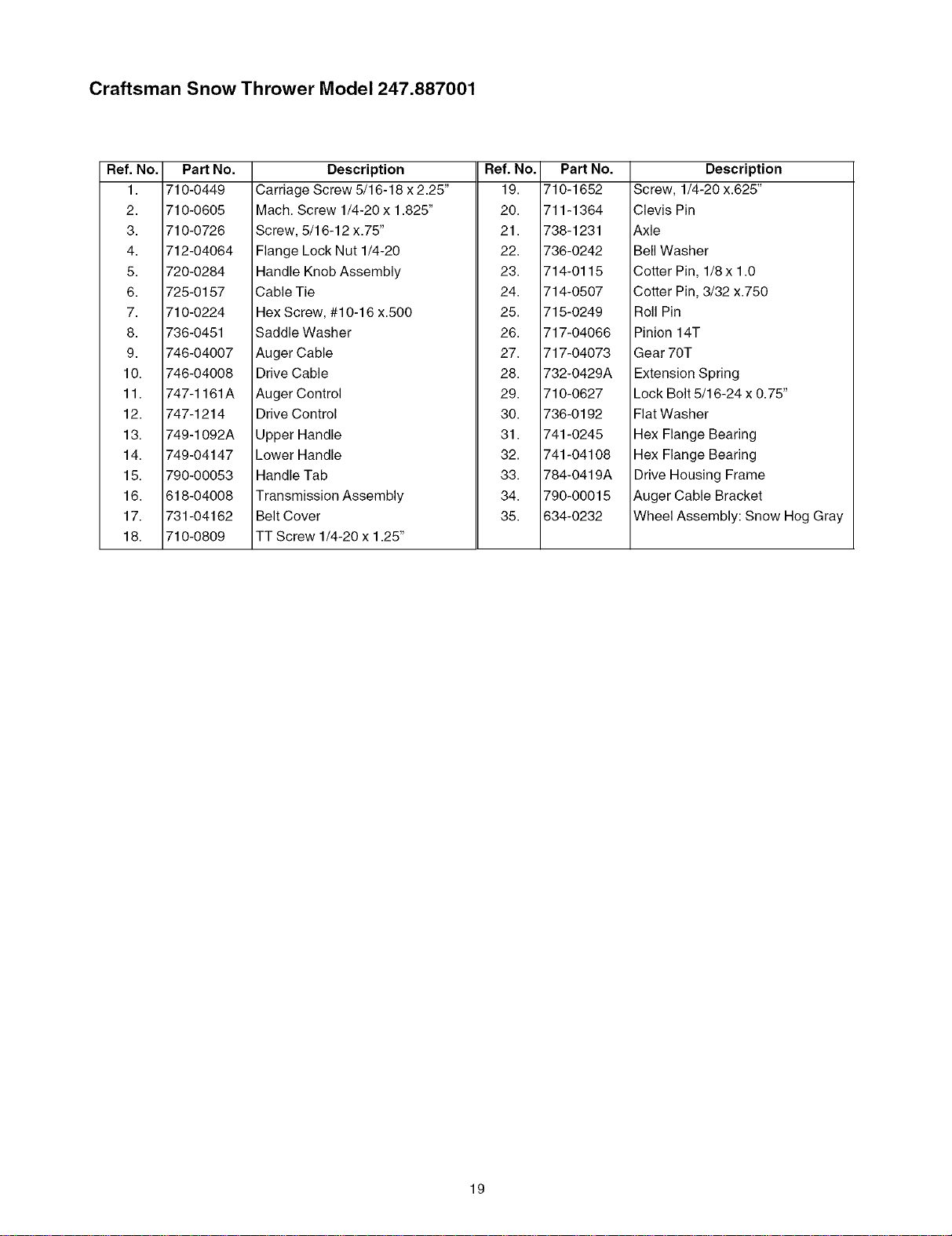
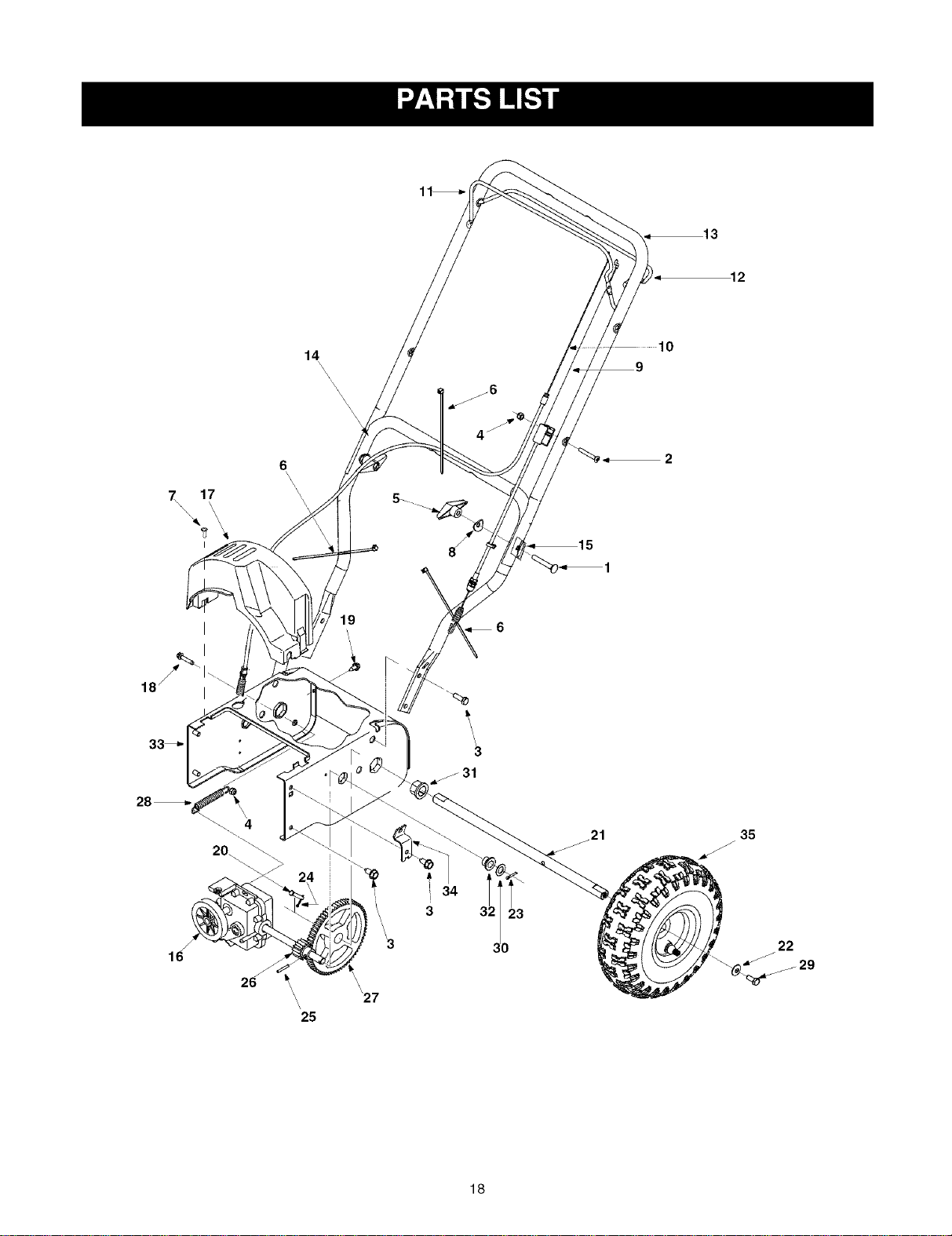
Craftsman Snow Thrower Model 247.887001
Ref. No. Part No.
1. 710-0449
2. 710-0605
3. 710-0726
4. 712-04064
5. 720-0284
6. 725-0157
7. 710-0224
8. 736-0451
9. 746-04007
10. 746-04008
11. 747-1161A
12. 747-1214
13. 749-1092A
14. 749-04147
15. 790-00053
16. 618-04008
17. 731-04162
18. 710-0809
Description
Carriage Screw 5/16-18 x 2.25"
Mach. Screw 1/4-20 x 1.825"
Screw, 5/16-12 x.75"
Flange Lock Nut 1/4-20
Handle Knob Assembly
Cable Tie
Hex Screw, #10-16 x.500
Ref. No.
19.
20.
21.
22.
23.
24.
25.
Part No.
710-1652
711-1364
738-1231
736-0242
714-0115
714-0507
715-0249
Description
Screw, 1/4-20 x.625"
Clevis Pin
Axle
Bell Washer
Cotter Pin, 1/8x 1.0
Cotter Pin, 3/32 x.750
Roll Pin
Saddle Washer
Auger Cable
Drive Cable
Auger Control
Drive Control
Upper Handle
Lower Handle
Handle Tab
Transmission Assembly
Belt Cover
TT Screw 1/4-20 x 1.25"
26.
27.
28.
29.
30.
31.
32.
33.
34.
35.
717-04066
717-04073
732-0429A
710-0627
736-0192
741-0245
741-04108
784-0419A
790-00015
634-0232
Pinion 14T
Gear 70T
Extension Spring
Lock Bolt 5/16-24 x 0.75"
Fiat Washer
Hex Flange Bearing
Hex Flange Bearing
Drive Housing Frame
Auger Cable Bracket
Wheel Assembly: Snow Hog Gray
19
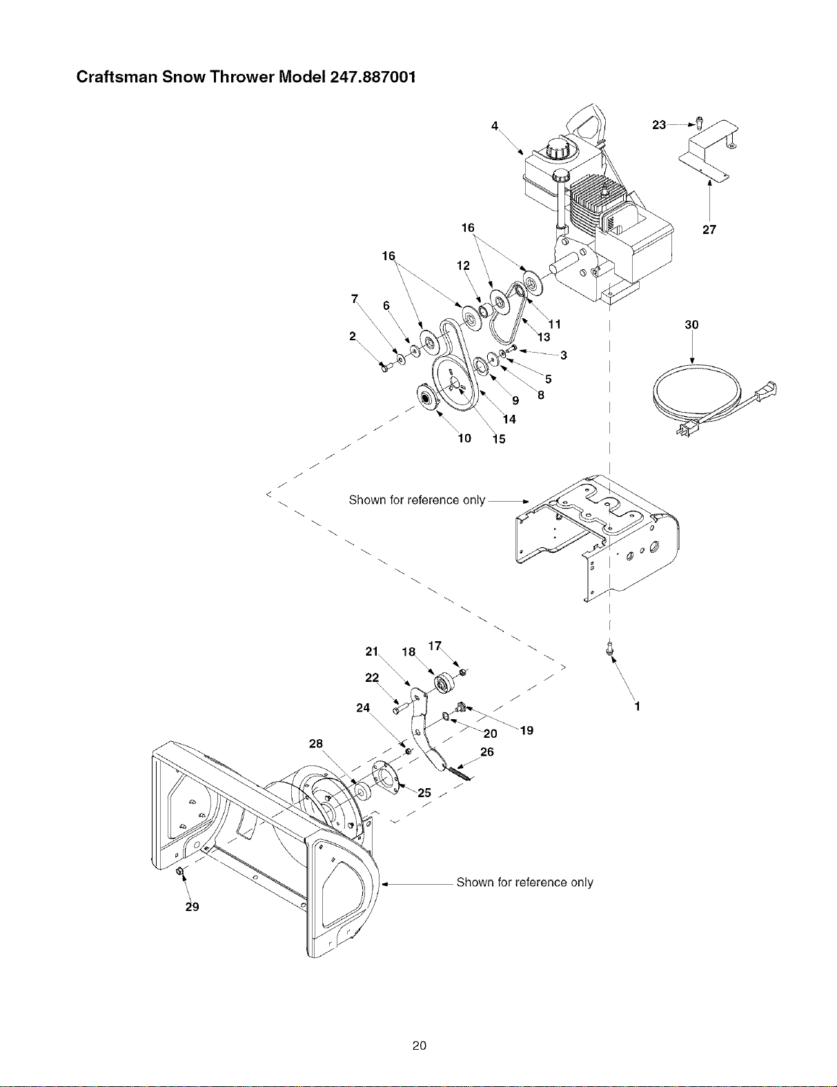
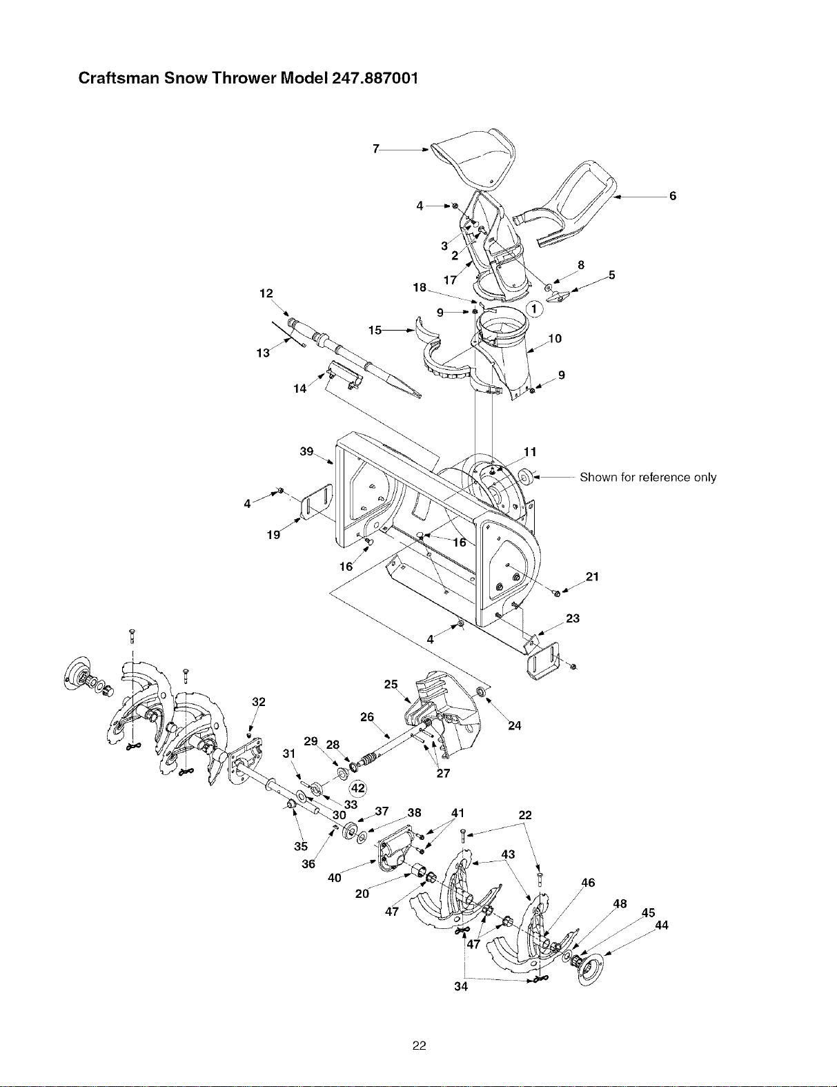
Craftsman Snow Thrower Model 247.887001
4
\\\\
16
27
12
J
J
J
J
28
Shown for reference only
21\\\
22 \
24
>
J
\
\
\
\
\
'1
30
Shown for reference only
2O
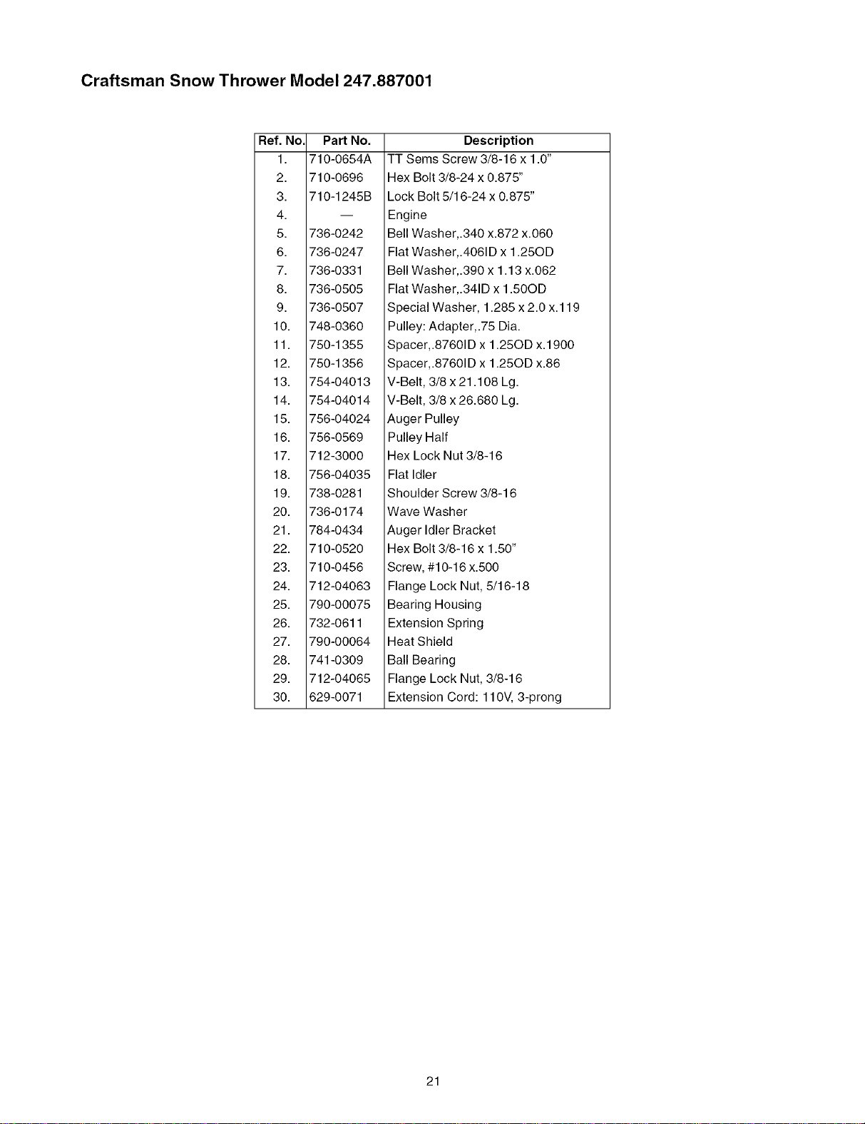
Craftsman Snow Thrower Model 247.887001
Ref. No. Part No.
1. 710-0654A
2. 710-0696
3. 710-1245B
4.
5. 736-0242
6. 736-0247
7. 736-0331
8. 736-0505
9. 736-0507
10. 748-0360
11. 750-1355
12. 750-1356
13. 754-04013
14. 754-04014
15. 756-04024
16. 756-0569
17. 712-3000
18. 756-04035
19. 738-0281
20. 736-0174
21. 784-0434
22. 710-0520
23. 710-0456
24. 712-04063
25. 790-00075
26. 732-0611
27. 790-00064
28. 741-0309
29. 712-04065
30. 629-0071
Description
TT Sems Screw 3/8-16 x 1.0"
Hex Bolt 3/8-24 x 0.875"
Lock Bolt 5/16-24 x 0.875"
Engine
Bell Washer,.340 x.872 x.060
Flat Washer,.4061D x 1.25OD
Bell Washer,.390 x 1.13 x.062
Flat Washer,.341D x 1.50OD
Special Washer, 1.285 x 2.0 x.119
Pulley: Adapter,.75 Dia.
Spacer,.87601D x 1.25OD x.1900
Spacer,.87601D x 1.25OD x.86
V-Belt, 3/8 x 21.108 Lg.
V-Belt, 3/8 x 26.680 Lg.
Auger Pulley
Pulley Half
Hex Lock Nut 3/8-16
Flat Idler
Shoulder Screw 3/8-16
Wave Washer
Auger Idler Bracket
Hex Bolt 3/8-16 x 1.50"
Screw, #10-16 x.500
Flange Lock Nut, 5/16-18
Bearing Housing
Extension Spring
Heat Shield
Ball Bearing
Flange Lock Nut, 3/8-16
Extension Cord: 110V, 3-prong
21
Craftsman Snow Thrower Model 247.887001
12
\
13_
18_ 1
11
Shown for reference only
19
25
31
29
\
36
2_
\\
20
27
_38 41
47
22
43
21
34
22
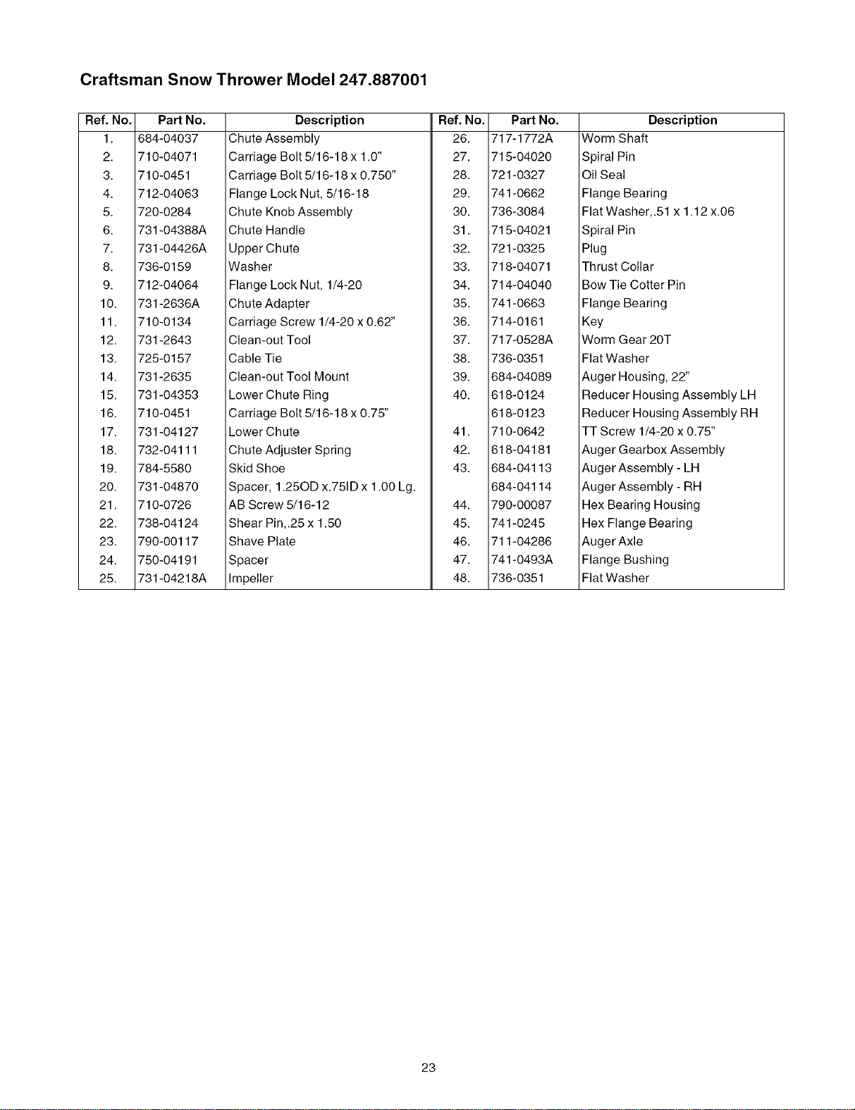
Craftsman Snow Thrower Model 247.887001
Ref. No.
1.
2.
3.
4.
5.
6.
7.
8.
9.
10.
11.
12.
13.
14.
15.
16.
17.
18.
19.
20.
21.
22.
23.
24.
25.
PaN No.
684-04037
710-04071
710-0451
712-04063
720-0284
731-04388A
731-04426A
736-0159
712-04064
731-2636A
710-0134
731-2643
725-0157
731-2635
731-04353
710-0451
731-04127
732-04111
784-5580
731-04870
710-0726
738-04124
790-00117
750-04191
731-04218A
Description
Chute Assembly
Carriage Bolt 5/16-18 x 1.0"
Carriage Bolt 5/16-18 x 0.750"
Flange Lock Nut, 5/16-18
Chute Knob Assembly
Chute Handle
Upper Chute
Washer
Flange Lock Nut, 1/4-20
Chute Adapter
Carriage Screw 1/4-20 x 0.62"
Clean-out Tool
Cable Tie
Clean-out Tool Mount
Lower Chute Ring
Carriage Bolt 5/16-18 x 0.75"
Lower Chute
Chute Adjuster Spring
Skid Shoe
Spacer, 1.25OD x.751D x 1.00 Lg.
Ref. No.
26.
27.
28.
29.
30.
31.
32.
33.
34.
35.
36.
37.
38.
39.
40.
41.
42.
43.
Part No.
717-1772A
715-04020
721-0327
741-0662
736-3084
715-04021
721-0325
718-04071
714-04040
741-0663
714-0161
717-0528A
736-0351
684-04089
618-0124
618-0123
710-0642
618-04181
684-04113
684-04114
Description
Worm Shaft
Spiral Pin
Oil Seal
Flange Bearing
Flat Washer,.51 x 1.12 x.06
Spiral Pin
Plug
Thrust Collar
Bow Tie Cotter Pin
Flange Bearing
Key
Worm Gear 20T
Fiat Washer
Auger Housing, 22"
Reducer Housing Assembly LH
Reducer Housing Assembly RH
TT Screw 1/4-20 x 0.75"
Auger Gearbox Assembly
Auger Assembly - LH
Auger Assembly - RH
AB Screw 5/16-12
Shear Pin,.25 x 1.50
Shave Plate
Spacer
Impeller
44.
45.
46.
47.
48.
790-00087
741-0245
711-04286
741-0493A
736-0351
Hex Bearing Housing
Hex Flange Bearing
Auger Axle
Flange Bushing
Flat Washer
23
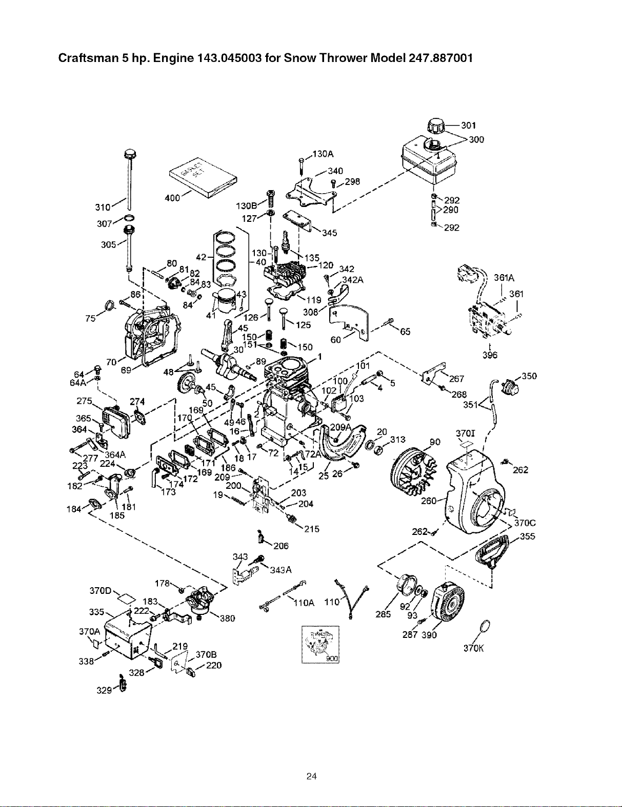
Craftsman 5 hp. Engine 143.045003 for Snow Thrower Model 247.887001
223
219
>
370B
25 26"/
203
361A
285 93
287 390
370K
24
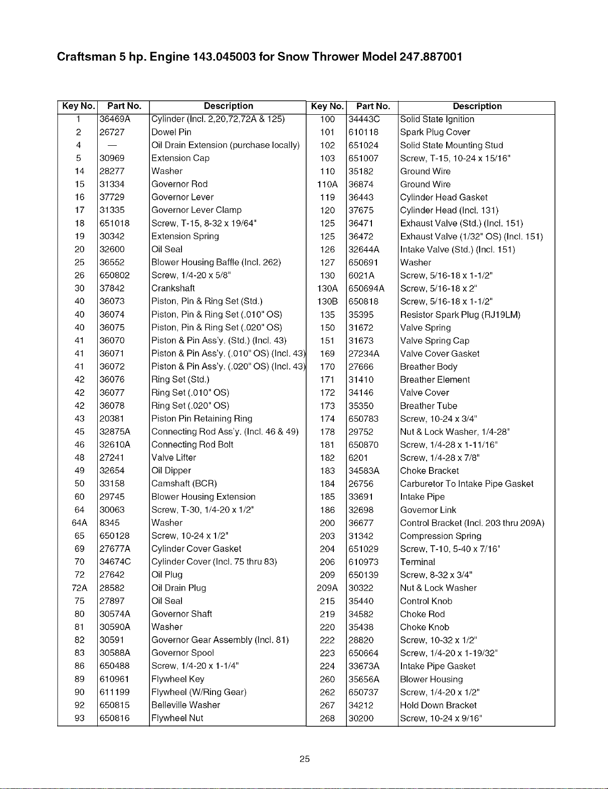
Craftsman 5 hp. Engine 143.045003 for Snow Thrower Model 247.887001
Key No.
1
2
4
5
14
15
16
17
18
19
20
25
26
3O
40
4O
40
41
41
41
42
42
42
43
45
46
48
49
50
60
64
64A
65
69
70
72
72A
75
80
81
82
83
86
89
90
92
93
Part No.
36469A
26727
30969
28277
31334
37729
31335
651018
30342
32600
36552
650802
37842
36073
36074
36075
36070
36071
36072
36076
36077
36078
20381
32875A
32610A
27241
32654
33158
29745
30063
8345
650128
27677A
34674C
27642
28582
27897
30574A
30590A
30591
30588A
650488
610961
611199
650815
650816
Description Key No.
Cylinder (Incl. 2,20,72,72A & 125) 100
Dowel Pin 101
Oil Drain Extension (purchase locally) 102
Extension Cap 103
Washer 110
Governor Rod 110A
Governor Lever 119
Governor Lever Clamp 120
Screw, T-15, 8-32 x 19/64" 125
Extension Spring 125
Oil Seal 126
Blower Housing Baffle (Incl. 262) 127
Screw, 1/4-20 x 5/8" 130
Crankshaft 130A
Piston, Pin & Ring Set (Std.) 130B
Piston, Pin & Ring Set (.010" OS) 135
Piston, Pin & Ring Set (.020" OS) 150
Piston & Pin Ass'y. (Std.) (Incl. 43) 151
Piston & Pin Ass'y. (.010" OS) (Incl. 43) 169
Piston & Pin Ass'y. (.020" OS) (Incl. 43) 170
Ring Set (Std.) 171
Ring Set (.010" OS) 172
Ring Set (.020" OS) 173
Piston Pin Retaining Ring 174
Connecting Rod Ass'y. (Incl. 46 & 49) 178
Connecting Rod Bolt 181
Valve Lifter 182
Oil Dipper 183
Camshaft (BCR) 184
Blower Housing Extension 185
Screw, T-30, 1/4-20 x 1/2" 186
Washer 200
Screw, 10-24 x 1/2" 203
Cylinder Cover Gasket 204
Cylinder Cover (Incl. 75 thru 83) 206
Oil Plug 209
Oil Drain Plug 209A
Oil Seal 215
Governor Shaft 219
Washer 220
Governor Gear Assembly (Incl. 81) 222
Governor Spool 223
Screw, 1/4-20 x 1-1/4" 224
Flywheel Key 260
Flywheel (W/Ring Gear) 262
Belleville Washer 267
Flywheel Nut 268
PaN No.
34443C
610118
651024
651007
35182
36874
36443
37675
36471
36472
32644A
650691
6021A
650694A
650818
35395
31672
31673
27234A
27666
31410
34146
35350
650783
29752
650870
6201
34583A
26756
33691
32698
36677
31342
651029
610973
650139
30322
35440
34582
35438
28820
650664
33673A
35656A
650737
34212
30200
Description
Solid State Ignition
Spark Plug Cover
Solid State Mounting Stud
Screw, T-15, 10-24 x 15/16"
Ground Wire
Ground Wire
Cylinder Head Gasket
Cylinder Head (Incl. 131)
Exhaust Valve (Std.) (Incl. 151)
Exhaust Valve (1/32" OS) (Incl. 151)
Intake Valve (Std.) (Incl. 151 )
Washer
Screw, 5/16-18 x 1-1/2"
Screw, 5/16-18 x 2"
Screw, 5/16-18 x 1-1/2"
Resistor Spark Plug (RJ19LM)
Valve Spring
Valve Spring Cap
Valve Cover Gasket
Breather Body
Breather Element
Valve Cover
Breather Tube
Screw, 10-24 x 3/4"
Nut & Lock Washer, 1/4-28"
Screw, 1/4-28 x 1-11/16"
Screw, 1/4-28 x 7/8"
Choke Bracket
Carburetor To Intake Pipe Gasket
Intake Pipe
Governor Link
Control Bracket (Incl. 203 thru 209A)
Compression Spring
Screw, T-10, 5-40 x 7/16"
Terminal
Screw, 8-32 x 3/4"
Nut & Lock Washer
Control Knob
Choke Rod
Choke Knob
Screw, 10-32 x 1/2"
Screw, 1/4-20 x 1-19/32"
Intake Pipe Gasket
Blower Housing
Screw, 1/4-20 x 1/2"
Hold Down Bracket
Screw, 10-24 x 9/16"
25
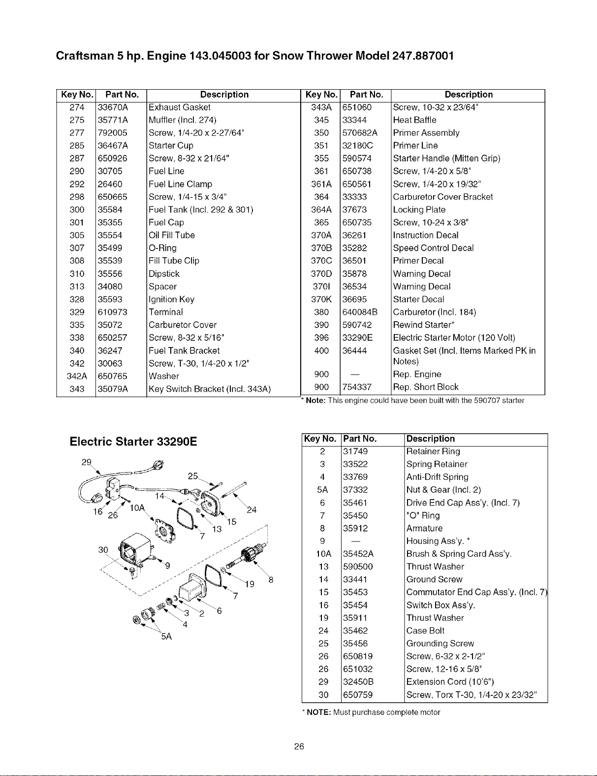
Craftsman 5 hp. Engine 143.045003 for Snow Thrower Model 247.887001
Key No.
274
275
277
285
287
29O
292
298
3OO
301
3O5
3O7
308
310
313
328
329
335
338
340
342
342A
343
Part No.
33670A
35771A
792005
36467A
650926
30705
26460
650665
35584
35355
35554
35499
35539
35556
34080
35593
610973
35072
650257
36247
30063
650765
35079A
Description
Exhaust Gasket
Muffler (Incl. 274)
Screw, 1/4-20 x 2-27/64"
Starter Cup
Screw, 8-32 x 21/64"
Fuel Line
Fuel Line Clamp
Screw, 1/4-15 x 3/4"
Fuel Tank (Incl. 292 & 301)
Fuel Cap
Oil Fill Tube
O-Ring
Fill Tube Clip
Dipstick
Spacer
Ignition Key
Terminal
Carburetor Cover
Screw, 8-32 x 5/16"
Fuel Tank Bracket
Screw, T-30, 1/4-20 x 1/2"
Washer
Key Switch Bracket (Incl. 343A)
Key No. Part No.
343A 651060
345 33344
350 570682A
351 32180C
355 590574
361 650738
361A 650561
364 33333
364A 37673
365 650735
370A 36261
370B 35282
370C 36501
370D 35878
3701 36534
370K 36695
380 640084B
390 590742
396 33290E
400 36444
900
900 754337
Description
Screw, 10-32 x 23/64"
Heat Baffle
Primer Assembly
Primer Line
Starter Handle (Mitten Grip)
Screw, 1/4-20 x 5/8"
Screw, 1/4-20 x 19/32"
Carburetor Cover Bracket
Locking Plate
Screw, 10-24 x 3/8"
Instruction Decal
Speed Control Decal
Primer Decal
Warning Decal
Warning Decal
Starter Decal
Carburetor (Incl. 184)
Rewind Starter*
Electric Starter Motor (120 Volt)
Gasket Set (Incl. Items Marked PK in
Notes)
Rep. Engine
Rep. Short Block
Note: This engine could have been built with the 590707 starter
Electric Starter 33290E
29
25.
30
\
13
7
\4
5A
7
Key No. PaN No.
2 31749
3 33522
4 33769
5A 37332
6 35461
7 35450
8 35912
9
10A 35452A
13 590500
14 33441
15 35453
16 35454
19 35911
24 35462
25 35456
26 650819
26 651032
29 32450B
30 650759
*NOTE:
Description
Retainer Ring
Spring Retainer
Anti-Drift Spring
Nut & Gear (Incl. 2)
Drive End Cap Ass'y. (Incl. 7)
"O" Ring
Armature
Housing Ass'y. *
Brush & Spring Card Ass'y.
Thrust Washer
Ground Screw
Commutator End Cap Ass'y. (Incl. 7)
Switch Box Ass'y.
Thrust Washer
Case Bolt
Grounding Screw
Screw, 6-32 x 2-1/2"
Screw, 12-16 x 5/8"
Extension Cord (10'6")
Screw, Torx T-30, 1/4-20 x 23/32"
Must purchase complete motor
26
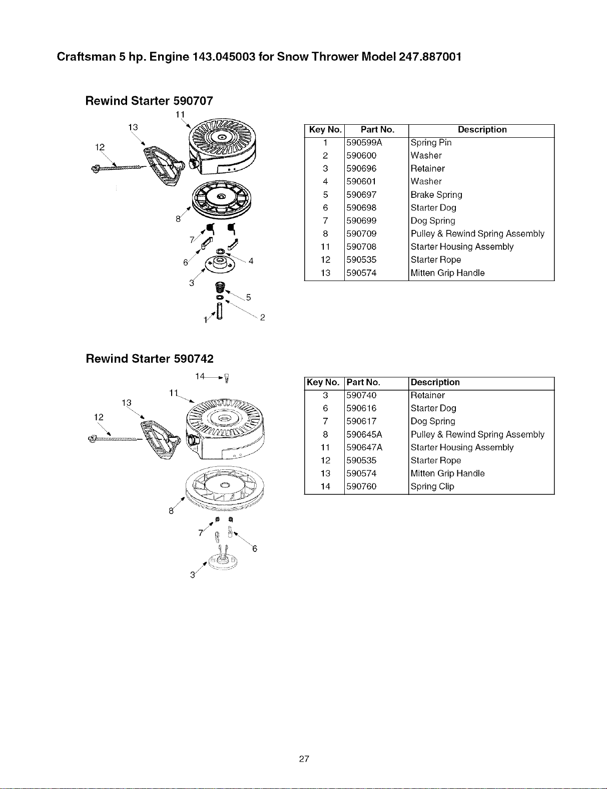
Craftsman 5 hp. Engine 143.045003 for Snow Thrower Model 247.887001
Rewind Starter 590707
11
,\
13 "_
\\\\:_
\\
/
Key No. PaN No.
1 590599A
2 590600
3 590696
4 590601
5 590697
6 590698
7 590699
8 590709
11 590708
12 590535
13 590574
Description
Spring Pin
Washer
Retainer
Washer
Brake Spring
Starter Dog
Dog Spring
Pulley & Rewind Spring Assembly
Starter Housing Assembly
Starter Rope
Mitten Grip Handle
Rewind Starter 590742
14_
11.
Key No.
3
6
7
8
11
12
13
14
Part No.
590740
590616
590617
590645A
590647A
590535
590574
590760
Description
Retainer
Starter Dog
Dog Spring
Pulley & Rewind Spring Assembly
Starter Housing Assembly
Starter Rope
Mitten Grip Handle
Spring Clip
27
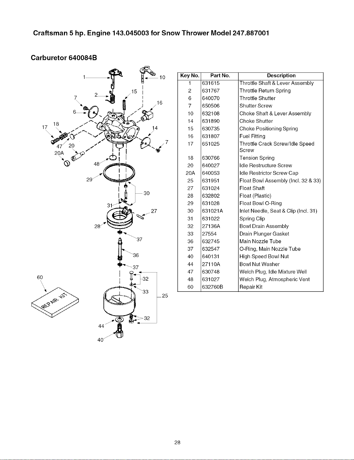
Craftsman 5 hp. Engine 143.045003 for Snow Thrower Model 247.887001
Carburetor 640084B
Key No.
1
2
6
7
10
14
15
16
17
18
2O
20A
25
27
28
29
3O
31
32
33
36
37
4O
44
47
48
6O
Part
631615
631767
640070
650506
632108
631890
630735
631807
651025
630766
640027
640053
631951
631024
632802
631028
631021A
631022
27136A
27554
632745
632547
640131
27110A
630748
631027
632760B
NO.
Description
Throttle Shaft & Lever Assembly
Throttle Return Spring
Throttle Shutter
Shutter Screw
Choke Shaft & Lever Assembly
Choke Shutter
Choke Positioning Spring
Fuel Fitting
Throttle Crack Screw/Idle Speed
Screw
Tension Spring
Idle Restructure Screw
Idle Restrictor Screw Cap
Float Bowl Assembly (Incl. 32 & 33)
Float Shaft
Float (Plastic)
Float Bowl O-Ring
Inlet Needle, Seat & Clip (Incl. 31)
Spring Clip
Bowl Drain Assembly
Drain Plunger Gasket
Main Nozzle Tube
O-Ring, Main Nozzle Tube
High Speed Bowl Nut
Bowl Nut Washer
Welch Plug, Idle Mixture Well
Welch Plug, Atmospheric Vent
Repair Kit
40_
28
Contenido Pag.
Informaci6n sobre la garantia ............................ 29
Practicas de seguridad en la operaci6n ............. 30
Ensamblado ....................................................... 32
Operaci6n .......................................................... 34
Mantenimiento ................................................... 38
Contenido Pag.
Servicio y Ajuste ................................................ 40
Almacenamiento fuera de temporada ................ 42
Guia para la soluci6n de problemas ................... 43
Lista de las piezas (English) .............................. 18
Garantia de dos afios para la m&quina quitanieve Craftsman
Durante dos afios a partir de la fecha de compra, siempre que a esta maquina quitanieve se le realice el servicio de
mantenimiento, lubricaci6n y sintonizaci6n de acuerdo alas instrucciones del manual del propietario, Sears reparara sin
cargo cualquier defecto de materiales o mano de obra.
Si esta m_tquina quitanieve Craftsman se utiliza para prop6sitos comerciales o de alquiler, esta garantia se aplica s61o
durante 30 d(as a partir de la fecha de compra.
Esta garantia no cubre:
Elementos desechables que se desgastan por el uso normal, incluyendo entre otros, zapatas antideslizantes, placa de
raspado, y buj(as.
Reparaciones necesarias debido a abuso o negligencia del operador, incluyendo abolladura del cigQefial y falla por no
realizar mantenimiento del equipo de acuerdo con las instrucciones contenidas en el manual del propietario. EL SERVICIO
DE GARANTIA EST, _, DISPONIBLE PARA LOS USUARIOS QUE LLEVEN LA M,_,QUINA QUITANIEVE CRAFTSMAN AL
CENTRO DE PARTES & REPARACION SEARS MAS CERCANO DENTRO DE LOS ESTADOS UNIDOS.
Esta garantia es valida t]nicamente mientras el producto se utilice dentro de los Estados Unidos.
Esta garantia le otorga derechos legales especfficos; usted tambien puede tener otros derechos, los cuales varian de un
estado a otro.
SEARS, ROEBUCK AND CO., D/817WA, HOFFMAN ESTATES, IL 60179
Acuerdos de protecci6n sobre reparaciones
Felicitaciones por la compra inteligente que realiz6. Su nuevo
producto Craftsman@ esta diseflado y fabricado para afios de
operacidn confiable. Pero como todo producto, es posible que
necesite reparaciones de vez en cuando. En esos casos tener un
Acuerdo de Proteccidn sobre Reparaciones le ahorrara dinero y
disgustos.
El Acuerdo incluye Io siguiente:
Servicio especializado Ilevado a cabo por 12,000
*/ especialistas profesionales en reparaciones
Servicio ilimitado sin costo para partes y mano de obra
en todas las reparaciones cubiertas
Reemplazo del productosi no es posible arreglar el
*/ producto cubierto per el acuerdo
Descuento del 10% sobre el precio regular de servicio y
partes relacionadas con el servicio no cubiertas por el
acuerdo; adem4s descuento de110% sobre el precio
regular para control de mantenimiento preventivo
Ayuda rapida por tel_fono - apoyo telef6nico de un
*_ t_cnico de Sears para los productes que requieran
reparaciones en el sitio mas un cronegrama de
reparaciones conveniente.
Compre un Acuerdo de Protecci6n sebre Reparaciones ya mismo y
evite problemas y gastos inesperados.
Una vez que compre el Acuerdo, s61otendra que realizar una
Ilamada telef6nica para programar el servicio. Llame en cualquier
momento de dia o de noche o acuerde una cita de servicio en I(nea.
Sears tiene alrededor de 12,000 especialistas en reparaciones
profesionales, los cuales tienen acceso a 4.5 millones de partes y
accesorios de calidad. Esa es la clase de profesionalismo con que
cuenta para ayudar a prolongar la vida de su nueva compra durante
los afios siguientes, iCompre hoy mismo el Acuerdo de Protecci6n
sobre Reparaciones!
Se aplican algunas limitaciones y exclusiones. Para obtener
informacidn adicional y precios Ilame al 1-800-827-6655.
Servicio de instalaci6n de Sears
Para la instalacidn profesional de Sears de aparatos dom_sticos,
dispositivos de apertura de portones, calentadores de agua y otros
articulos del hogar, en los Estados Unidos Ilame al 1-800-4-MY-
HOME@.
Ikv_[o]m]_1n(o]_,L|Jkv4_1;{o]
Caballaje: 5
Aceite del motor: SAE 5W30
Combustible: Comt_n sin plomo
Buj(as: RJ19LM
Motor: Modelo de motor Craftsman 143.045003
Modelo Nt]mero
NOmero de Serie ........................................................
Fecha de compra ......................................................
Registre el nOmero de serie y la fecha de compra y
conserve esta informaci6n en un sitio seguro para
referencia futura.
29
ADVERTENClA: Este simbolo indica instrucciones de seguridad importantes que de no seguirse,
podrian poner en peligro la seguridad personal y/o la propiedad suya y de terceros. Lea y siga todas las
instrucciones en este manual antes de iniciar la operaci6n de esta maquina. En caso de no seguir estas
instrucciones podrian producirse lesiones personales. Cuando vea este simbolo--preste atenci6n a la
advertencia..
_ ADVERTENCIA: El escape del motor de este producto, algunos de sus componentes y algunoscomponentes del vehiculo contienen o emiten productos quimicos que el estado de California considera
que pueden producir c4ncer, defectos de nacimiento u otros problemas reproductivos.
PELIGRO: Esta maquina esta diseSada para set utilizada respetando las reglas de seguridad contenidas en este manual. AI
igual que con cualquier tipo de equipo electrico, una falla o error de parte del operador puede producir graves lesiones. Esta
maquina es capaz de amputar manos y pies y de arrojar objetos con gran fuerza. De no respetar las instrucciones de seguridad
siguientes se pueden producir lesiones graves o la muerte.
Capacitacion
1. Lea,coml)renda y respete todaslas instruccionesque figuran
en la maquina oen este(os) manual(es) antes de proceder al
ensamblado y ol)eraci6n del equil)o. Guarde este manual en un
lugar segurol)ara referencias futuras y regulates y para
solicitar l)artesde reemplazo.
2. Familiarfcese con todoslos controlesy con su funcionamiento.
Sepac6mo detener la m&quinay c6mo desengranar los
controles.
3. Nunca permita que niSos menores de 14aSos operen esta
m_.quina.Los nifios de 14 afios y mayores de 14 aSosdeben
leery comprender las instrucciones de ol)eraci6n y lasreglas
de seguridad contenidas en este manual y deben ser
entrenados y supervisadosper uno de los padres.
4. Nunca l)ermita queadultos sin los conocimientos adecuados
acerca de lam_.quinala ol)eren.
5. Los objetos arrojadosper la maquina l)ueden l)roducir lesiones
graves. Planifiqueel patr6nen el quevaa irarrojando nieve
l)ara evitarque la descarga de material se realice hacia los
caminos, los observadores, etc.
6. Mantenga alos observadores, ayudantes, mascotas y a los
nifios l)or Iomenos a75 pies de la maquina mientras la misma
esta en funcionamiento. Detenga la m_.quinasialguien entra en
la zona.
7. Sea l)recavido para evitar patinarse ocaerse especialmente
cuando opera la maquina en reversa.
Preparativos
1. Revise minuciosamente la zona dondese utilizar_,el equipo.
Saque todos los felpudos, peri6dicos, trineos, tablas, cables y
otros objetos extraSoscon losque podria trol)ezaro que
podrfan ser arrojados perla barrena / motor.
2. Para l)rotegerselos ojosutilice siempreanteojos oantil)arras
de seguridad mientras opera la maquJnao mientras la ajusta o
rel)ara.Los objetos arrojados que rebotan pueden lesionar
gravemente lavista.
3. No opere la maquina sinla vestimenta adecuada para estar al
aire libre en invierno. No utilice alhajas,bufandas largasu otras
l)rendas sueltasque podrian enredarse en las partesm6viles.
Utilice uncalzado especial l)ara superficies resbaladizas.
4. Use un cord6n prolongadory untomacorriente detres cables
con conexi6n atierra l)aratodas las unidadescon motores con
encendido electrico.
5. Ajuste laaltura de la cajadel tomacorriente para limpiarla
grava olas superficies con l)iedras trituradas.
6. Desengranetodas las l)alancas de embrague antes de
arrancar el motor.
7. Nunca intente realizar ajustes mientras el motoresta en
8,
9.
marcha excepto en los casos especMcamente recomendados
en elmanual del ol)erador.
Dejeque el motory lamaquina se adal)ten ala teml)eratura
exterior antes decomenzar a sacarla nieve.
Sea sumamente cuidadoso al manipular la gasolina paraevitar
lesiones o daSos. Lagasolina es altamente inflamable y los
vapores son explosives. Sel)uede lesionar gravemente si
derrama gasolina sobre ustedo sobre la ropa yaque se puede
l)render fuego. Lavela piely cambiese de rol)a de inmediato.
a. Utilice s6lo recipientes para gasolina al)robados.
b. Apague todos los cigarrillos, cigarros, l)il)as y otras
fuentes de combusti6n.
c. Nunca cargue combustible en la maquina en un
espaciocerrado.
d. Nunca saque la tapa del combustible ni agregue
combustible mientras el motoresta caliente oen
marcha.
e. Dejeque el motor seenfrfe per Iomenos dos minutos
antesde volver acargar combustible.
f. Nunca recargue el tanque de combustible. Llene el
tanque nomas de 1/2 pulgadal)or debajo de labase
delcuello del filtro para dejar espacio para la dilataci6n
delcombustible.
g. Vuelva acolocar la tapa de la gasolina y ajt]stela bien.
h. Limpie la gasolina derramada sobre el motor y el
equil)o. Traslade lam_.quinaa otra zona. Esl)ere 5
minutes antes de encenderel motor.
i. Nunca almacene la m_.quinao el recipiente de
combustible en un esl)acio cerrado donde hayafuego,
chispas o luz piloto (per ejemplo, hornos, calentadores
deagua, calefactores, secadores de ropa,etc.).
j. Dejeque lamaquina se enfrie durante 5 minutes antes
de almacenarla.
Operacion
1. No l)ongalas manes o los pies cercade las piezas rotatorias,
en lacaja de labarrena / motor oen el canal de descarga. El
contacto con piezas rotatoriasl)uede aml)utar manesy pies.
2. La palanca del embrague de la barrena/ motores un
disl)ositivo de seguridad. Nunca pasepor alto su
funcionamiento. De hacerlola operaci6n de la maquina es
riesgosa y puedeocasionar lesiones.
3. Las palancas del embrague deben funcionar bien enambas
direcciones y regresar autom_.ticamentea la posici6n de
desengrane cuandose las suelta.
4. Nunca el)ere la m_.quinasi falta un canalde descarga oel
mismo esta daSado.Mantenga todos los dispositivos de
seguridad en sulugar yen funcionamiento.
30
5. Nuncaenciendaelmotorenespacioscerradosoenunazona
pocoventilada.Elescapedelmotorcontienemon6xidode
carbono,ungasinodoroyletal.
6. NooperelamAquinaestandobajolosefectosdelalcoholode
drogas.
7. Elsilenciadoryelmotorsecalientanyproducenuna
quemadura.Nolostoque.
8. Seasumamenteprecavidocuandooperelam_.quinasobreuna
superficiecongravaocuandolacruce.Mantengasealertapor
sisepresentanpeligrosocultosotransito.
9. Tengacuidadocuandocambiededirecci6nocuandooperela
m_.quinaenpendientes.
10.Planifiqueelpatr6nenelquevaairarrojandonieveparaevitar
queladescargadematerialseproduzcahacialasventanas,
lasparedes,losautom6viles,etc.paraevitarposiblesdafios
materialesolesionesproducidasporlosrebotes.
11.Nuncadirijaladescargahacialosni_os,losobservadoresylas
mascotasnidejequenadieseparedelantedelamaquina.
12.Nosobrecarguelacapacidaddelam_.quinatratandodesacar
lanievemuyr_.pidamente.
13.Nuncaopereestamaquinasinotienebuenavisibilidado
iluminacion.Siempredebeestarsegurodequeestabien
afirmadoysostengabienlasmanijas.Camine,nuncacorra.
14.Cortelacorrientealabarrena/ motorcuandotransporte la
m_.quinaocuando la mismano esta en uso.
15. Nunca opere la m_.quinaa alta velocidad de desplazamiento
sobre superficies resbaladizas. Mirehacia abajo y haciaatrasy
tenga cuidado cuandola useen reversa.
16. Si lamaquina comenzara a vibrar de manera anormal, detenga
el motor, desconecte elcable de labujfa y pongala de manera
que haga masa contra el motor. Inspeccione la maquina
minuciosamente para ver siesta dafiada. Reparetodos los
dafios antesde encendery operar la m_.quina.
17. Desengrane todaslas palancas de embrague y detenga el
motorantes de dejar laposici6n de operaci6n (detras de las
manijas). Espere a que la barrena/ motorse detenga por
completo antes de destapar el canal de descarga, de realizar
ajustes o inspecciones.
18. Nunca ponga las manos en las aberturas de descarga o de
recolecci6n. Utilice siemprela herramienta de limpiezaque se
adjunta para destapar la abertura de descarga. No destape el
canal dedescarga mientras el motor est6.en marcha. Antesde
destaparlo, apagueel motor y permanezca detr_s de las
manijashasta que todas las partesmoviles se hayandetenido
completamente.
19. Uses61ouniones y accesorios aprobados por el fabricante (por
ejemplo, pesas para las ruedas, cadenas para los neum_.ticos,
cabinas, etc.).
20. Si sepresentan situaciones que no estan previstas eneste
manual sea cuidadoso y use el sentido com@. Contacte al
centro de servicio Sears para obtener asistencia.
Mantenimiento & Almacenamiento
1. Nunca manipule los dispositivos deseguridad de manera
imprudente. Controle peri6dicamente que funcionen de forma
adecuada. Remitase alas seccionesde mantenimiento y
ajuste de este manual.
2. Antes de realizar la limpieza, de reparar ode revisar la
m_.quina,desengranetodas las palancas deembrague y
detenga el motor. Espere a quela barrena / motor sedetenga
porcompleto. Desconecte elcable de la bujia y p6ngalode
manera quehaga masa contra el motor para evitar que se
encienda de manera accidental.
3. Verifique frecuentemente que lospernos y tornillos esten
ajustados correctamente para asegurarse de que la m_.quina
este trabajando de manera segura. Adem_.srealice una
inspeccion visualde la m_.quinapara controlar si la mismaesta
dafiada.
4. No cambie laconfiguraci6n del regulador delmotor ni acelere
demasiado elmismo. El regulador controla la velocidad
m_.ximasegura de operacion delmotor.
5. Las placas de raspadoy las zapatas antideslizantes que se
usan con la maquinaquitanieve se desgastan y se dafian. Para
proteger su seguridad,verifique frecuentemente todos los
componentes y reemplacelos s61oconpartes de losfabricantes
de equipos originales (OEM). "Lautilizaci6n de partesque no
cumplan con las especificaciones de equipos originales podrfa
tener como resultado un rendimiento incorrecto y ademas la
seguridad podrfaestar comprometida"
6. Reviselos controles del embrague peri6dicamente para
verificar que engranen y desengranen adecuadamente y
ajtJstelossi es necesario.Consulte la secci6n de ajustesen
este manualdel operador para obtener instrucciones.
7. Mantenga/reemplace lasetiquetas/instrucciones de seguridad
segt]n sea necesario.
8. Respete las leyesy reglamentaciones referentes a la
disposici6n correcta de combustible, aceite, etc. para proteger
el medio ambiente.
9. Antes de almacenar la m_.quinaenciendala unos minutos para
sacar la nieveque hayaquedado en la mismay para evitar asi
que se congele la barrena/ motor.
10. Nunca almacene la m_.quinaoelrecipiente de combustible en
un espacio cerrado donde hayafuego, chispas oluz piloto
como por ejemplo, calentadores de agua, hornos, secadores
de ropa, etc.
11. Siempre consulte el manual del operador para obtener
instrucciones correctas acerca delalmacenamiento fuera de
temporada.
Su responsabilidad:
S61opermita que usen esta m_.quinaelectrica las personas que
lean,comprendan y respeten las advertencias y las instrucciones
queaparecen en este manual yen la m_.quina.A continuaci6n se
muestranlas etiquetas de seguridad parasu referencia.
No modifique el motor
Para evitar lesiones graves o la muerte, no modifique el motor
bajo ninguna circunstancia. Si cambia la configuraci6n del
regulador el motor puede descontrolarse y operar a
velocidades inseguras. Nunca cambie la configuracidn de
fabrica del regulador del motor.
Aviso referido a emisiones
Los motores que esta.n certificados y cumplen con las
regulaciones de emisiones federales EPA y de California
para SORE (Equipos Small Off Road Equipment) estan
certificados para operar con gasolina comt]n sin plomo y
pueden incluir los siguientes sistemas de control de
emisiones: Modificacion de motor (EM) y catalizador de tres
vias (TWC) siesta equipado de esa manera.
Calcomania de identificaci6n del motor
Estacalcomania indica el nL)merodel modelo delmotor, las
especificacionesy lafecha de fabricacidn. Por favor mire la
calcomanfaen el motorde suequipo y registreesa informaci6npara
referenciafutura.
Lacalcomaniadeidentificacidndelmotortambienincluye
especificacionessobreelperiododevida t]tildelmotorrelacionadocon
lasemisiones.Esteperiodoesta.relacionadoconlavidat]til en
conformidadconlas emisionessegLinIocertificadoporEPAy/oCARB.
Parahallarla especificacidndel periododevidat]til delmotor,porfavor
lealacalcomaniadelmotory ubiquela/etra (entrecomillas)entrelas
palabrasModeradoy PeriododeVidaUtil.Conecteunadelas
siguientesletrasconla letraimpresaensucalcomanfa.Porejemplo,a
losmodelosHSSKselos designacomo:
"C" -- 125 horas; "B" -- 250 horas; "A" -- 500 horas
31
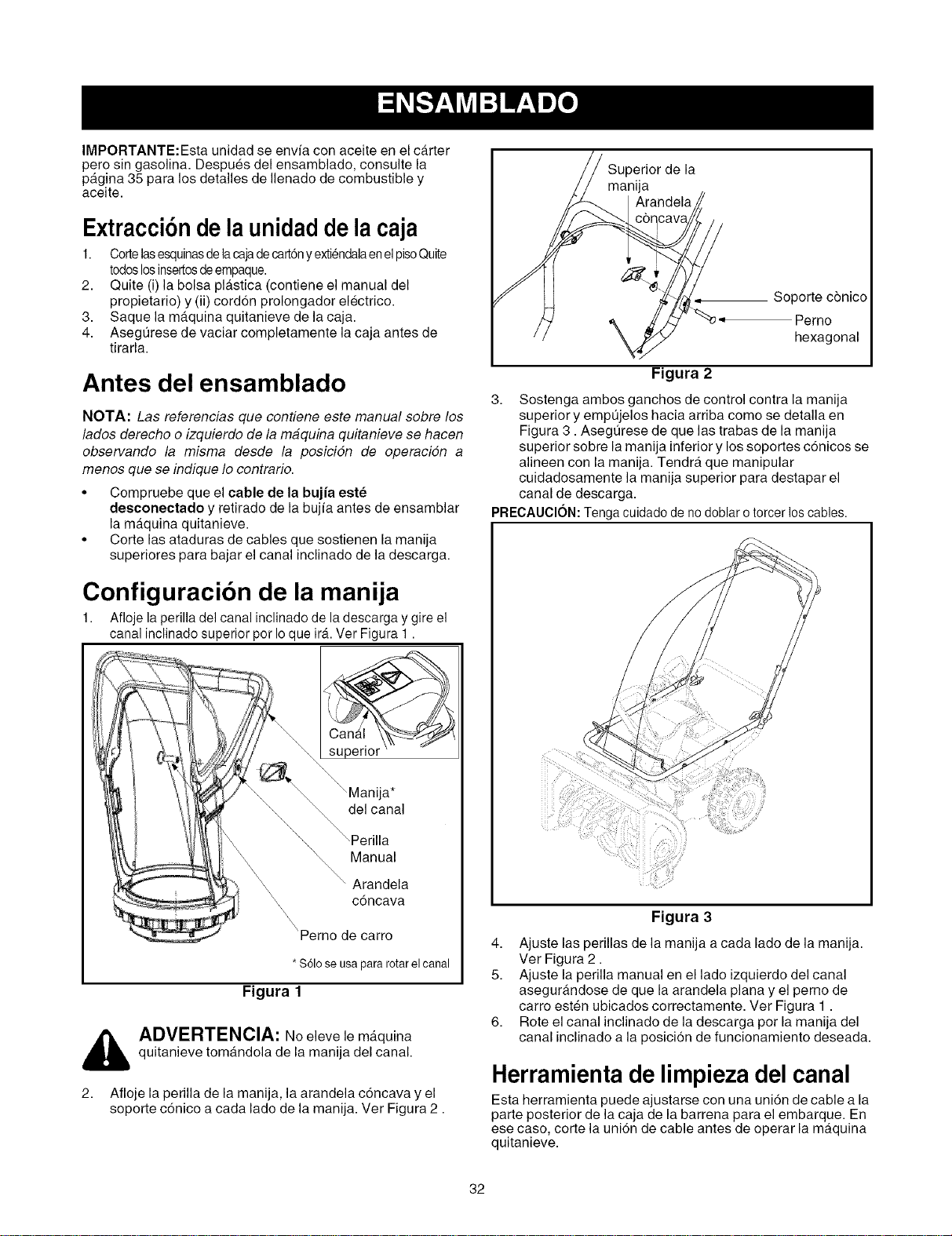
IMPORTANTE:Esta unidad se envfa con aceite en el carter
pero sin gasolina. Despues del ensamblado, consulte la
pagina 35 para los detalles de Ilenado de combustible y
aceite.
Extracci6ndela unidaddela caja
1. Cortelasesquinasdelacajadecart6ny extiendalaenel pisoQuite
todoslosinsertosdeempaque.
2. Quite (i) la bolsa plastica (contiene el manual del
propietario) y (ii) cord6n prolongador electrico.
3. Saque la maquina quitanieve de la caja.
4. Asegt]rese de vaciar completamente la caja antes de
tirarla.
Antes del ensamblado
NOTA: Las referencias que contiene este manual sobre los
lados derecho o izquierdo de la maquina quitanieve se hacen
observando la misma desde la posicidn de operacidn a
menos que se indique Io contrario.
• Compruebe que el cable de la bujia eete
desconectado y retirado de la bujfa antes de ensamblar
la maquina quitanieve.
• Corte las ataduras de cables que sostienen la manija
superiores para bajar el canal inclinado de la descarga.
Configuracibn de la manija
1. Afloje la perilla del canal inclinado de la descarga y gire el
canal inclinado superior per Io que irA.Ver Figura 1.
su erior '
ija*
delcanal
Manual
Arandela
c6ncava
'Perno de carro
*SOloseusapararotarelcanal
Figura 1
,_ ADVERTENCIA: No eleve le maquina
quitanieve tomandola de la manija del canal.
2. Afloje la perilla de la manija, la arandela c6ncava y el
soporte c6nico a cada lado de la manija. Ver Figura 2.
Superior de la
manija
Arandela
\
Soporte c6nico
'_ -_ Perno
hexagonal
Figura 2
3. Sostenga ambos ganchos de control contra la manija
superior y empt]jelos hacia arriba como se detalla en
Figura 3. Asegt]rese de que las trabas de la manija
superior sobre la manija inferior y los soportes c6nicos se
alineen con la manija. Tendra que manipular
cuidadosamente la manija superior para destapar el
canal de descarga.
PRECAUCION:Tenga cuidado de nodoblar otorcer loscables.
Figura 3
4. Ajuste las perillas de la manija a cada lado de la manija.
Ver Figura 2.
5. Ajuste la perilla manual en el lado izquierdo del canal
asegurandose de que la arandela plana y el perno de
carro esten ubicados correctamente. Ver Figura 1.
6. Rote el canal inclinado de la descarga por la manija del
canal inclinado a la posicion de funcionamiento deseada.
Herramienta de limpieza del canal
Esta herramienta puede ajustarse con una uni6n de cable a la
parte posterior de la caja de la barrena para el embarque. En
ese caso, corte la uni6n de cable antes de operar la maquina
quitanieve.
32
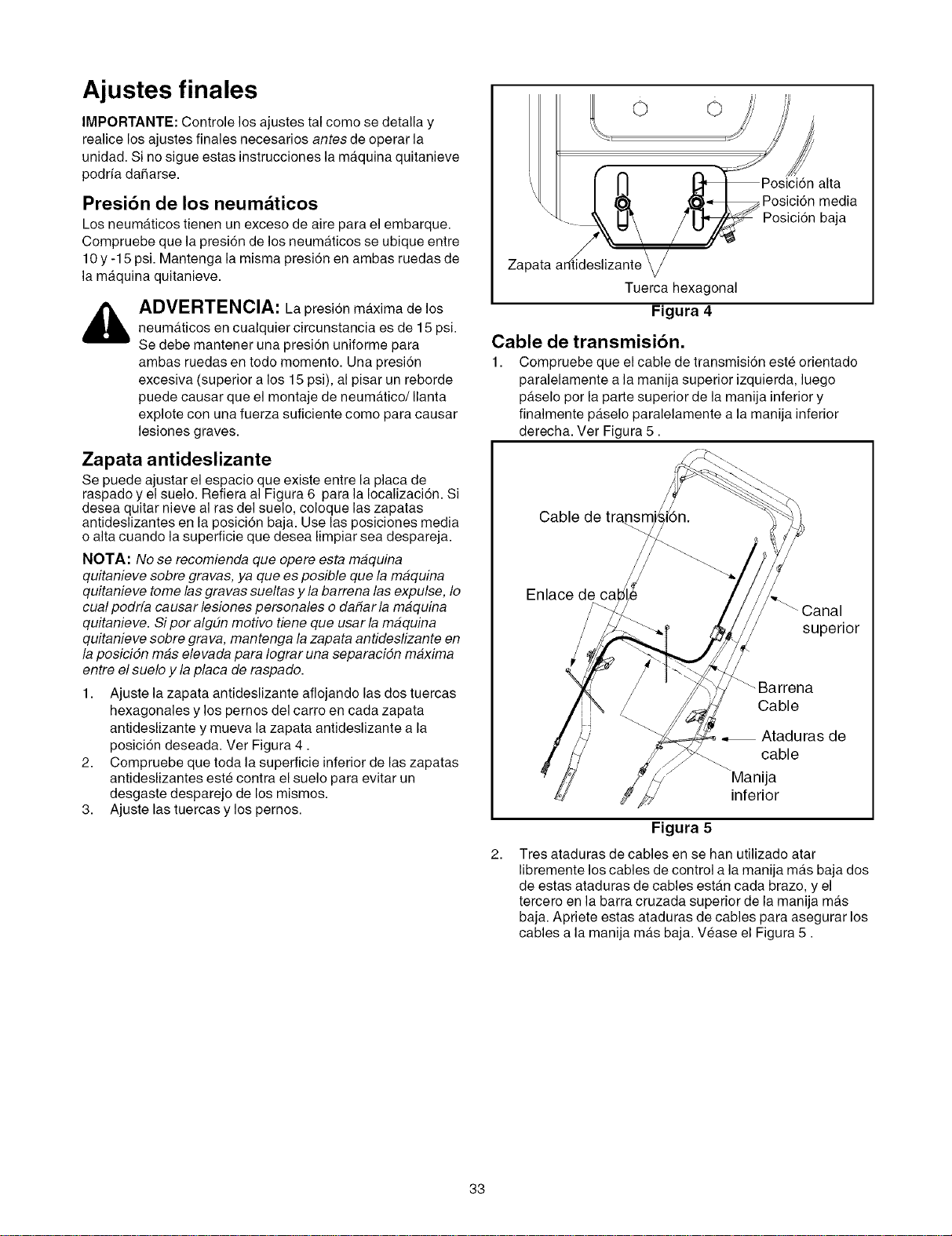
Ajustes finales
IMPORTANTE: Controle los ajustes tal como se detalla y
realice los ajustes finales necesarios antes de operar la
unidad. Si no sigue estas instrucciones la maquina quitanieve
podrfa daharse.
Presibn de los neum_ticos
Los neumaticos tienen un exceso de aire para el embarque.
Compruebe que la presi6n de los neumaticos se ubique entre
10 y -15 psi. Mantenga la misma presi6n en ambas ruedas de
la maquina quitanieve.
ADVERTENCIA: La presion maxima de los
neumAticos en cualquier circunstancia es de 15 psi.
Se debe mantener una presion uniforme para
ambas ruedas en todo momento. Una presi6n
excesiva (superior a los 15 psi), al pisar un reborde
puede causar que el montaje de neumatico/Ilanta
explote con una fuerza suficiente como para causar
lesiones graves.
Zapata antideslizante
Se puede ajustar el espacio que existe entre la placa de
raspado y el suelo. Refiera al Figura 6 para la Iocalizaci6n. Si
desea quitar nieve al ras del suelo, coloque las zapatas
antideslizantes en la posicion baja. Use las posiciones media
o alta cuando la superficie que desea limpiar sea despareja.
NOTA: No se recomienda que opere esta maquina
quitanieve sobre gravas, ya que es posible que la maquina
quitanieve tome las gravas sueltas y la barrena las expulse, Io
cual podrfa causar lesiones p ersonales o da#ar la maquina
quitanieve. Si por alg#n motivo tiene que usar la maquina
quitanieve sobre grava, mantenga la zapata antideslizante en
la posicidn mas elevada para Iograr una separaciSn maxima
entre el suelo y la placa de raspado.
1. Ajuste la zapata antideslizante aflojando las dos tuercas
hexagonales y los pernos del carro en cada zapata
antideslizante y mueva la zapata antideslizante a la
posici6n deseada. Vet Figura 4.
2. Compruebe que toda la superficie inferior de las zapatas
antideslizantes este contra el suelo para evitar un
desgaste desparejo de los mismos.
3. Ajuste las tuercas y los pernos.
o o
alta
Posici6n media
Posici6n baja
Tuerca hexagonal
Figura 4
Cable de transmisibn.
1. Compruebe que el cable de transmisi6n este orientado
paralelamente a la manija superior izquierda, luego
paselo per la parte superior de la manija inferior y
finalmente paselo paralelamente a la manija inferior
derecha. Ver Figura 5.
Cable de
Enlace de cal
superior
2.
_Barrena
Cable
Ataduras de
cable
Manija
inferior
Figura 5
Tres ataduras de cables en se han utilizado atar
libremente los cables de control a la manija mas baja dos
de estas ataduras de cables estan cada brazo, y el
tercero en la barra cruzada superior de la manija mas
baja. Apriete estas ataduras de cables para asegurar los
cables a la manija mas baja. Vease el Figura 5.
33
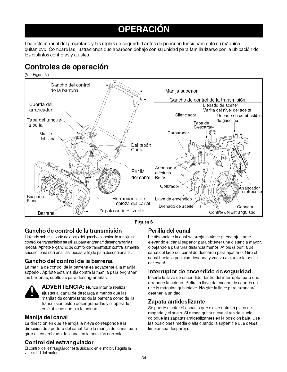
Lea este manual del propietario y las reglas de seguridad antes de poner en funcionamiento su maquina
quitanieve. Compare las ilustraciones que aparecen debajo con su unidad para familiarizarse con la ubicaci6n de
los distintos controles y ajustes.
Controles de operacibn
(Ver Figura 6)
de la barrena.
Cuerda del
arrancador _
\
la bujia
Manija
.p6n
Canal
Manija superior
Gancho de control de la transmisidn
Llenado de aceite/
Varilla del nivel del aceite
Silenciador gasoliIa
Tapade / Leenado de combustible
I Descarga*
Carb<rador
\
\
\
\
\\
\Perilla electrico
del canal Bot6n
Placa
Barrend
Herramienta de
limpieza del canal
Zapata antideslizante
Llave de
Drenado de aceite
,rrancador
le retroceso
\
Cebador
Contrbl del estrangulador
Figura 6
Gancho de control de la transmisibn
Ubicada sobre la parte de abajo delgancho superior, lamanija de
control de transmision seutiliza para engranar/desengranar las
ruedas. Apriete elgancho de control de transmisi6n contra lamanija
superior para engranar las ruedas,afl6jela para desengranarla.
Gancho del control de la barrena.
La manija de control de la barrena es adyacente a la manija
superior. Apriete esta manija contra la manija para engranar
las barrenas; sueltelas para desengranarlas.
_ DVERTENCIA: Nunca intente realizarajustes al canal de descarga a menos que las
manijas de control tanto de la barrena come de la
transmisi6n esten desengranadas y el operador
este ubicado junto a la unidad.
Manija del canal
La direccion en que se arroja la nieve corresponde a la
direccion de apertura del canal. Use la manija del canal para
girar el ensamblado del canal en la posicion correcta.
Control del estrangulador
El control del estrangulador est,. ubicado enel motor. Regulala
velocidad del motor.
Perilla del canal
La distancia a la cual se arroja la nieve puede ajustarse
elevando el canal superior para obtener una distancia mayor,
o bajandola para una distancia menor. Afloje la perilla del
canal del lado del canal de descarga para ajustarlo. Gire el
canal hacia la posicion deseada y vuelva a ajustar la perilla
del canal.
Interruptor de encendido de seguridad
Inserte la Ilave de encendido dentro del interrupter para que
arranque la unidad. Retire la Ilave de encendido cuando no
use la maquina quitanieve. No gire la Ilave para arrancar/
detener la unidad.
Zapata antideslizante
Se puede ajustar el espacio que existe entre la placa de
raspado y el suelo. Si desea quitar nieve al ras del suelo,
coloque las zapatas antideslizantes en la posici6n baja. Use
las posiciones media o alta cuando la superficie que desea
limpiar sea despareja.
34
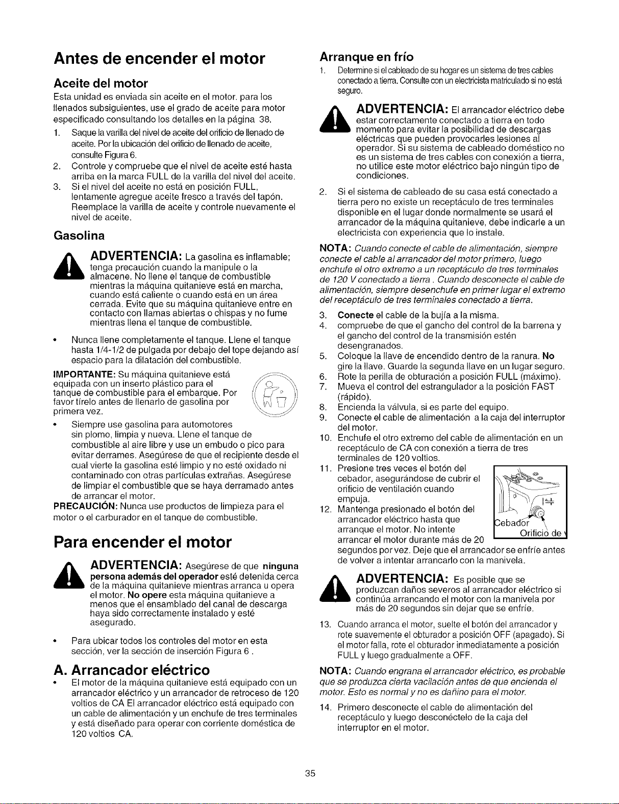
Antes de encender el motor
Aceite del motor
Esta unidad es enviada sin aceite en el motor, para los
Ilenados subsiguientes, use el grado de aceite para motor
especificado consultando los detalles en la pagina 38.
1. Saque lavarilla del nivelde aceite del orificiode Ilenadode
aceite. Por la ubicaci6n del orificio de Ilenado de aceite,
consulte Figura 6.
2. Controle y compruebe que el nivel de aceite este hasta
arriba en la marca FULL de la varilla del nivel del aceite.
3. Si el nivel del aceite no esta en posici6n FULL,
lentamente agregue aceite fresco a traves del tap6n.
Reemplace la varilla de aceite y controle nuevamente el
nivel de aceite.
Gasolina
_ DVERTENCIA: La gasolina es inflamable;
tenga precauci6n cuando la manipule o la
almacene. No Ilene el tanque de combustible
mientras la maquina quitanieve esta en marcha,
cuando esta caliente o cuando esta en un Area
cerrada. Evite que su maquina quitanieve entre en
contacto con llamas abiertas o chispas y no fume
mientras Ilena el tanque de combustible.
Arranque en frio
1. Determinesiel cableadodesuhogaresunsistemadetrescables
conectadoatierra.ConsulteconunelectricistamatriculadosinoestA
seguro.
_ DVERTENClA: El arrancador el6ctrico debe
estar correctamente conectaclo a tierra en todo
momento para evitar la posibilidad de descargas
el6ctricas que pueden provocarles lesiones al
operador. Si su sistema de cableado domestico no
es un sistema de tres cables con conexi6n a tierra,
no utilice este motor electrico bajo ningQn tipo de
condiciones.
2. Si el sistema de cableado de su casa esta conectado a
tierra pero no existe un receptaculo de tres terminales
disponible en el lugar donde normalmente se usara el
arrancador de la maquina quitanieve, debe indicarle a un
electricista con experiencia que Io instale.
NOTA: Cuando conecte el cable de alimentacidn, siempre
conecte el cable al arrancador del motor primero, luego
enchufe el otro extremo a un receptaculo de tres terminales
de 120 V conectado a tierra . Cuando desconecte el cable de
alimentacidn, siempre desenchufe en primer lugar el extremo
del receptaculo de tres terminales conectado a tierra.
3.
4.
• Nunca Ilene completamente el tanque. Llene el tanque
hasta 1/4-1/2 de pulgada por debajo del tope dejando asf
espacio para la dilatacion del combustible. 5.
IMPORTANTE: Su maquina quitanieve esta 6.
equipada con un inserto plastico para el 7.
tanque de combustible para el embarque. Por
favor tffelo antes de Ilenarlo de gasolina por 8.
primera vez. 9.
• Siempre use gasolina para automotores
sin plomo, limpia y nueva. Llene el tanque de 10.
combustible al aire libre y use un embudo o pico para
evitar derrames. AsegQrese de que el recipiente desde el
cual vierte la gasolina este limpio y no este oxidado ni 11.
contaminado con otras partfculas extraSas. AsegQrese
de limpiar el combustible que se haya derramado antes
de arrancar el motor.
PRECAUClON: Nunca use productos de limpieza para el 12.
motor o el carburador en el tanque de combustible.
Para encender el motor
ADVERTENCIA: AsegQrese de que ninguna
persona ademas del operador este detenida cerca
de la maquina quitanieve mientras arranca u opera
el motor. No opere esta maquina quitanieve a
menos que el ensamblado del canal de descarga
haya sido correctamente instalado y este
asegurado.
• Para ubicar todos los controles del motor en esta
secci6n, ver la secci6n de inserci6n Figura 6.
A. Arrancador el6ctrico
• El motor de la maquina quitanieve esta equipado con un
arrancador el6ctrico y un arrancador de retroceso de 120
voltios de CA El arrancador electrico esta equipado con
un cable de alimentaci6n y un enchufe de tres terminales
y esta disehado para operar con corriente domestica de
120 voltios CA.
Conecte el cable de la bujfa a la misma.
compruebe de que el gancho del control de la barrena y
el gancho del control de la transmisi6n esten
desengranados.
Coloque la Ilave de encendido dentro de la ranura. No
gire la Ilave. Guarde la segunda Ilave en un lugar seguro.
Rote la perilla de obturacion a posicion FULL (maximo).
Mueva el control del estrangulador a la posicion FAST
(rapido).
Encienda la vMvula, si es parte del equipo.
Conecte el cable de alimentaci6n a la caja del interruptor
del motor.
Enchufe el otro extremo del cable de alimentacion en un
receptaculo de CA con conexion a tierra de tres
terminales de 120 voltios.
Presione tres veces el boton del
cebador, asegurandose de cubrir el
orificio de ventilacion cuando
empuja.
Mantenga presionado el boton del
arrancador el6ctrico hasta que
arranque el motor. No intente
arrancar el motor durante mas de 20
segundos por vez. Deje que el arrancador se enfrfe antes
de volver a intentar arrancarlo con la manivela.
_ ADVERTENCIA: Es posible que se
produzcan daSos severos al arrancador el6ctrico si
continQa arrancando el motor con la manivela por
mas de 20 segundos sin dejar que se enfrfe.
13. Cuando arranca el motor, suelte el bot6n del arrancador y
rote suavemente el obturador a posici6n OFF (apagado). Si
el motor falla, rote el obturador inmediatamente a posici6n
FULL y luego gradualmente a OFF.
NOTA: Cuando engrana el arrancador electrico, es probable
que se produzca cierta vacilacidn antes de que encienda el
motor. Esto es normal y no es da#ino para el motor.
14. Primero desconecte el cable de alimentaci6n del
receptaculo y luego descon6ctelo de la caja del
interruptor en el motor.
35
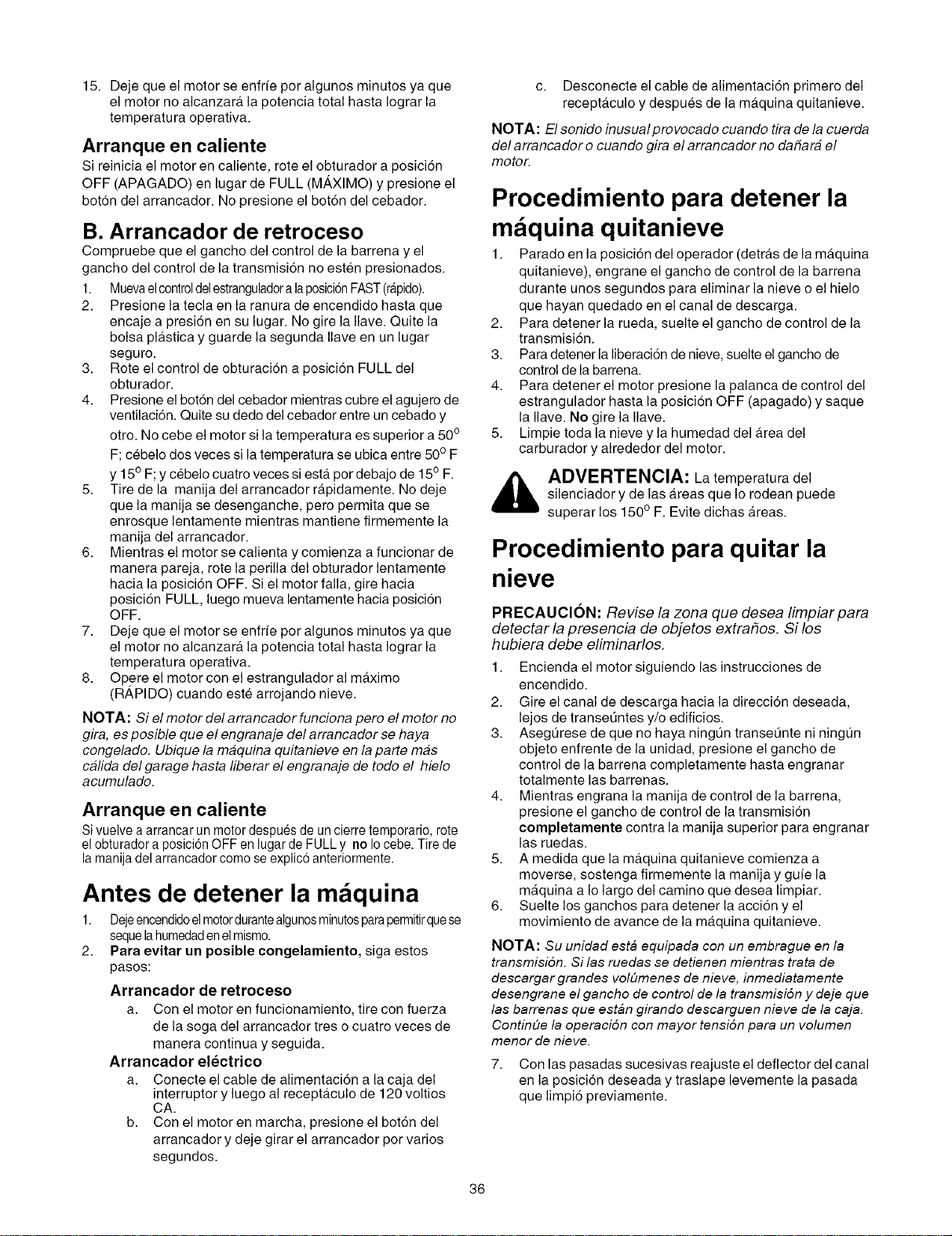
15.Dejequeelmotorseenfrfeporalgunosminutosyaque
elmotornoalcanzaralapotenciatotalhastaIograrla
temperaturaoperativa.
Arranque en caliente
Si reinicia el motor en caliente, rote el obturador a posici6n
OFF (APAGADO) en lugar de FULL (M_,XIMO) y presione el
boton del arrancador. No presione el bot6n del cebador.
B. Arrancador de retroceso
Compruebe que el gancho del control de la barrena y el
gancho del control de la transmisi6n no esten presionados.
1. Muevaelcontroldelestranguladoralaposici6nFAST(rapido).
2. Presione la tecla en la ranura de encendido hasta que
encaje a presi6n en su lugar. No gire la Ilave. Quite la
bolsa plAstica y guarde la segunda Ilave en un lugar
seguro.
3. Rote el control de obturaci6n a posiciSn FULL del
obturador.
4. Presione el botSn del cebador mientras cubre el agujero de
ventilaci6n. Quite su dedo del cebador entre un cebado y
otro. No cebe el motor si la temperatura es superior a 500
F; cebelo dos veces si la temperatura se ubica entre 50° F
y 15° F;y cebelo cuatro veces siestA pot debajo de 150 F.
5. Tire de la manija del arrancador rApidamente. No deje
que la manija se desenganche, pero permita que se
enrosque lentamente mientras mantiene firmemente la
manija del arrancador.
6. Mientras el motor se calienta y comienza a funcionar de
manera pareja, rote la perilla del obturador lentamente
hacia la posici6n OFF. Si el motor falla, gire hacia
posiciSn FULL, luego mueva lentamente hacia posici6n
OFF.
7. Deje que el motor se enfrfe por algunos minutos ya que
el motor no alcanzarA la potencia total hasta Iograr la
temperatura operativa.
8. Opere el motor con el estrangulador al maximo
(R_,PIDO) cuando este arrojando nieve.
NOTA: Si el motor del arrancador funciona pero el motor no
gira, es posible que el engranaje del arrancador se haya
congelado. Ubique la maquina quitanieve en la parte mas
calida del garage hasta liberar el engranaje de todo el hielo
acumulado.
Arranque en caliente
Si vuelve a arrancar un motordespues de uncierre temporario,rote
el obturador a posici6n OFF en lugar deFULL y no Iocebe.Tire de
la manija del arrancadorcomo se explic6 anteriormente.
Antes de detener la m quina
1. Dejeencendidoelmotordurantealgunosminutosparapermitirquese
sequela humedadenelmismo.
2. Para evitar un posible congelamiento, siga estos
pasos:
Arrancador de retroceso
a. Con el motor en funcionamiento, tire con fuerza
de la soga del arrancador tres o cuatro veces de
manera continua y seguida.
Arrancador el_ctrico
a. Conecte el cable de alimentaci6n a la caja del
interruptor y luego al recepta.culo de 120 voltios
CA.
b. Con el motor en marcha, presione el botSn del
arrancador y deje girar el arrancador por varios
segundos.
c. Desconecte el cable de alimentaci6n primero del
receptaculo y despues de la maquina quitanieve.
NOTA: El sonido inusual provocado cuando tira de la cuerda
del arrancador o cuando gira el arrancador no da#ara el
motor.
Procedimiento para detener la
m quina quitanieve
1. Parado en la posici6n del operador (detras de la maquina
quitanieve), engrane el gancho de control de la barrena
durante unos segundos para eliminar la nieve o el hielo
que hayan quedado en el canal de descarga.
2. Para detener la rueda, suelte el gancho de control de la
transmisi6n.
3. Para detener la liberacion de nieve, suelte el gancho de
control de la barrena.
4. Para detener el motor presione la palanca de control del
estrangulador hasta la posicion OFF (apagado) y saque
la Ilave. No gire la Ilave.
5. Limpie toda la nieve y la humedad del Area del
carburador y alrededor del motor.
_ ADVERTENCIA: La temperatura del
silenciador y de las Areas que Io rodean puede
superar los 150 ° F. Evite dichas Areas.
Procedimiento para quitar la
nieve
PRECAUCION: Revise la zona que desea limpiar para
detectar la presencia de objetos extra#os. Si los
hubiera debe eliminarlos.
1. Encienda el motor siguiendo las instrucciones de
encendido.
2. Gire el canal de descarga hacia la direcci6n deseada,
lejos de transet_ntes y/o edificios.
3. Asegt_rese de que no haya ningQn transet_nte ni ningun
objeto enfrente de la unidad, presione el gancho de
control de la barrena completamente hasta engranar
totalmente las barrenas.
4. Mientras engrana la manija de control de la barrena,
presione el gancho de control de la transmisi6n
completamente contra la manija superior para engranar
las ruedas.
5. A medida que la maquina quitanieve comienza a
moverse, sostenga firmemente la manija y gufe la
maquina a Io largo del camino que desea limpiar.
6. Suelte los ganchos para detener la acci6n y el
movimiento de avarice de la maquina quitanieve.
NOTA: Su unidad esta equipada con un embrague en la
transmisiSn. Si las ruedas se detienen mientras trata de
descargar grandes volbmenes de nieve, inmediatamente
desengrane el gancho de control de la transmisi6n y deje que
las barrenas que est_n girando descarguen nieve de la caja.
Continbe la operaciSn con mayortensi6n para un volumen
menor de nieve.
7. Con las pasadas sucesivas reajuste el deflector del canal
en la posicion deseada y traslape levemente la pasada
que limpi6 previamente.
36
Consejos de operacibn
NOTA: Deje que el motor se caliente unos minutos ya que el
mismo no desarrolla la potencia maxima hasta que alcanza la
temperatura de funcionamiento.
• Para que el quitado de la nieve sea mas eficiente debe
hacerlo inmediatamente despues de la cafda de la
misma.
• En Io posible, descargue la nieve en direccion al viento.
Traslape levemente las pasadas anteriores.
• Configure las zapatas antideslizantes 1/4" por debajo de
la barra de raspado para un uso normal. Las zapatas
antideslizantes se pueden ajustar hacia arriba cuando la
nieve este muy compactada.
NOTA: No se recomienda que opere esta maquina
quitanieve sobre gravas, ya que es posible que la maquina
quitanieve tome las gravas sueltas y la barrena las expulse, Io
cual podrfa causar lesiones personales y/o da#ar la maquina
quitanieve.
• Si por algOn motivo tiene que usar la maquina quitanieve
sobre grava, mantenga la zapata antideslizante en la
posicion ma.selevada para Iograr una separacidn
maxima entre el suelo y la placa de raspado.
• Limpie cuidadosamente la maquina quitanieve despues
de cada uso.
Herramienta de limpieza del canal
_L DVERTENCIA: Detenga el motor quitando
la Ilave de encendido y espere que se detengan
TODAS las partes moviles antes de usar la
herramienta de limpieza del canal.
La herramienta de limpieza esta ajustada convenientemente
a la parte posterior de lacaja de la barrena con una horquilla
de ensamblado. Ver 6. Vuelva acolocar la Ilave de encendido
y arranque el motor de la maquina quitanieve para continuar
quitando nieve..
Cuando se acumulen nieve y hielo en el canal de descarga
durante la operacion, use esta herramienta para limpiar de
manera segura el canal y la abertura del canal. Siga los
pasos que aparecen debajo para operarla:
1. Sueltelosganchosdecontrolde labarrenay latransmisi6n.
2. Para detener el motor saque la Ilave de encendido.
3. Saque la herramienta de limpieza de la horquilla que la
ajusta ala parte posterior de la caja de la barrena.
4. Use el extremo con forma de pala de la herramienta de
limpieza para desplazar y recoger la nieve y el hielo que se
formaron cerca del canal de descarga.
_ ADVERTENCIA: Nunca use sus manos para
limpiar la nieve y el hielo del canal de descarga o la
caja de la barrena.
5. Vuelva a ajustar laherramienta de limpieza delcanal a la
horquilla de ensamblado ubicado en la parteposterior de la
caja de la barrena.
6. Vuelva a colocar la Ilave deencendido y arranque elmotor de
la maquina quitanieve para continuar quitando nieve.
37
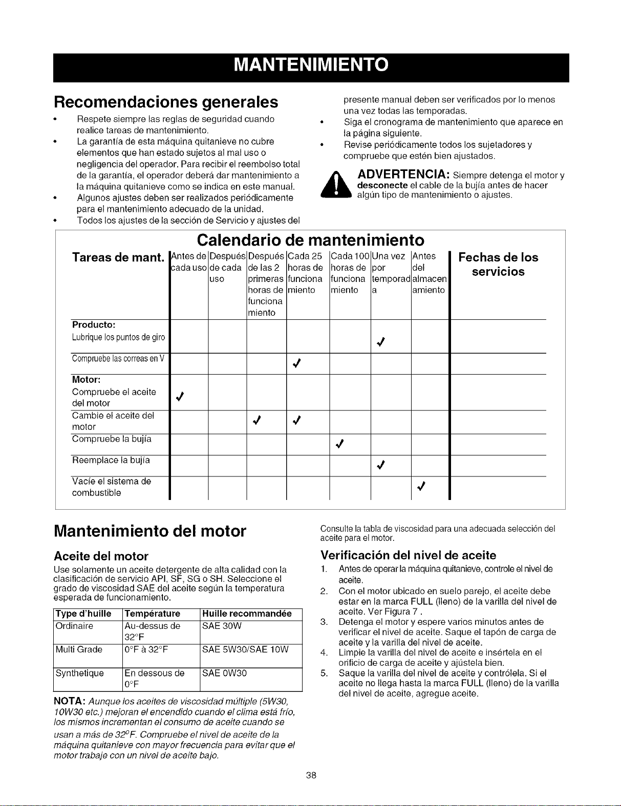
Recomendaciones generales
• Respete siempre las reglas de seguridad cuando
realice tareas de mantenimiento.
• La garantfa de esta maquina quitanieve no cubre
elementos que hart estado sujetos al real use o
negligencia del operador. Para recibir el reembolso total
de la garant[a, el operador debera, dar mantenimiento a
la ma.quina quitanieve come se indica en este manual.
• Algunos ajustes deben ser realizados peri6dicamente
para el mantenimiento adecuado de la unidad.
• Todos los ajustes de la secci6n de Servicio y ajustes del
Tareas de mant.
Producto:
Lubriquelospuntosdegiro
CompruebelascorreasenV
Motor:
Compruebe el aceite
del motor
Cambie el aceite del
motor
Compruebe la bujia
Reemplace la bujfa
Vacie el sistema de
combustible
4
presente manual deben set verificados per Io menos
una vez todas las temporadas.
• Siga el cronograma de mantenimiento que aparece en
la pagina siguiente.
• Revise peri6dicamente todos los sujetadores y
compruebe que esten bien ajustados.
_ DVERTENCIA: Siempre detenga el motor y
desconecte el cable de la bujia antes de hacer
algt]n tipo de mantenimiento o ajustes.
Calendario de mantenimiento
Cada 25
horas de
funciona
miento
¢
4
Cada 100
horas de
funciona
miento
4
4
Fechas de los
servicios
Mantenimiento del motor
Aceite del motor
Use solamente un aceite detergente de alta calidad con la
clasificaci6n de servicio API, SF, SG o SH. Seleccione el
grade de viscosidad SAE del aceite segt]n la temperatura
esperada de funcionamiento.
Type d'huille Temperature
Ordinaire Au-dessus de
32OF
Multi Grade 0°F & 32°F
Synthetique En dessous de
0OF
NOTA: Aunque los aceites de viscesidad m#ltiple (5W30,
10W30 etc.) mejoran el encendide cuando el clima esta fife,
los mismos incrementan el consume de aceite cuando se
usan a mas de 32°F. Cempruebe el nivel de aceite de la
maquina quitanieve con mayor frecuencia para evitar que el
motortrabaje con un nivel de aceite bajo.
Huille recommandee
SAE 30W
SAE 5W30/SAE 10W
SAE 0W30
Consulte latabla de viscosidad para unaadecuada selecci6n del
aceitepara el motor.
Verificacibn del nivel de aceite
1. Antes de operar lamaquina quitanieve, controle el nivel de
aceite.
2. Con el motor ubicado en suelo parejo, el aceite debe
estar en la marca FULL (lleno) de la varilla del nivel de
aceite. Ver Figura 7.
3. Detenga el motor y espere varies minutes antes de
verificar el nivel de aceite. Saque el tapon de carga de
aceite y la varilla del nivel de aceite.
4. Limpie la varilla del nivel de aceite e insertela en el
orificio de carga de aceite y ajt]stela bien.
5. Saque la varilla del nivel de aceite y contr61ela. Si el
aceite no Ilega hasta la marca FULL (lleno) de la varilla
del nivel de aceite, agregue aceite.
38
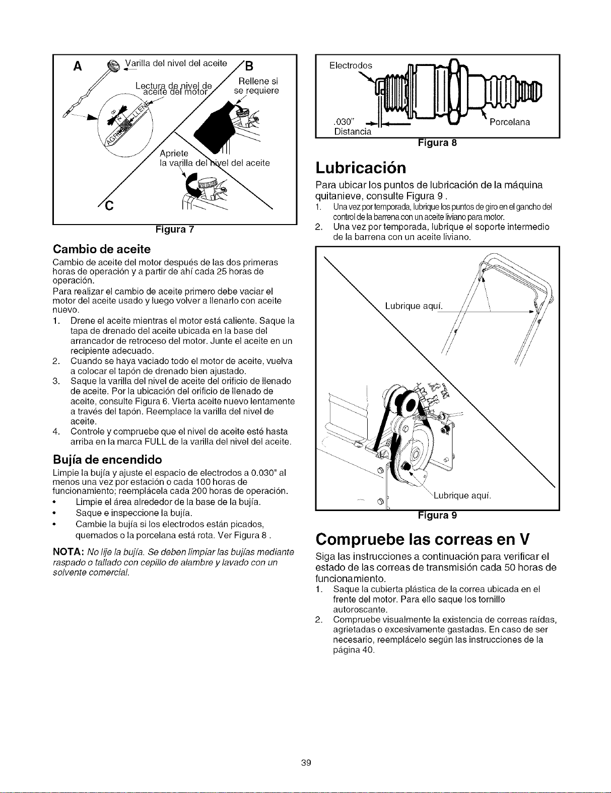
A
Varilla del nivel del aceite
Rellene si
se/requiere
aceite
/c
Figura 7
Cambio de aceite
Cambio de aceite del motor despues de las dos primeras
horas de operacion y a partir de ah/cada 25 horas de
operaci6n.
Para realizar el cambio de aceite primero debe vaciar el
motor del aceite usado y luego volver a Ilenarlo con aceite
nuevo.
1. Drene el aceite mientras el motor esta caliente. Saque la
tapa de drenado del aceite ubicada en la base del
arrancador de retroceso del motor. Junte el aceite en un
recipiente adecuado.
2. Cuando se haya vaciado todo el motor de aceite, vuelva
a colocar el tap6n de drenado bien ajustado.
3. Saque la varilla del nivel de aceite del orificio de Ilenado
de aceite. Por la ubicaci6n del orificio de Ilenado de
aceite, consulte Figura 6. Vierta aceite nuevo lentamente
a traves del tapon. Reemplace la varilla del nivel de
aceite.
4. Controle y compruebe que el nivel de aceite este hasta
arriba en la marca FULL de la varilla del nivel del aceite.
Bujia de encendido
Limpie la bujfa y ajuste el espacio de electrodos a 0.030" al
menos una vez por estaci6n o cada 100 horas de
funcionamiento; reemplacela cada 200 horas de operacion.
• Limpie el area alrededor de la base de la bujfa.
• Saque e inspeccione la bujfa.
• Cambie la bujfa si los electrodos estan picados,
quemados o la porcelana esta rota. Vet Figura 8.
NOTA: No lije la bujfa. Se deben limpiar las bujfas mediante
raspado o tallado con cepillo de alambre y lavado con un
solvente comercial.
Electrodos
.030" Porcelana
Distancia
Figura 8
Lubricaci6n
Para ubicar los puntos de lubricacidn de la maquina
quitanieve, consulte Figura 9.
1. Unavezportemporada,hbriquelospuntosdegiroenelganchodel
controlde labarrenaconunaceitelivianoparamotor.
2. Una vez pot temporada, lubrique el soporte intermedio
de la barrena con un aceite liviano.
Lubrique aquf.
lue aqul.
Figura 9
Compruebe las correas en V
Siga las instrucciones a continuaci6n para verificar el
estado de las correas de transmisidn cada 50 horas de
funcionamiento.
1. Saque la cubierta plastica de la correa ubicada en el
frente del motor. Para ello saque los tornillo
autoroscante.
2. Compruebe visualmente la existencia de correas rafdas,
agrietadas o excesivamente gastadas. En caso de ser
necesario, reemplacelo segt]n las instrucciones de la
pagina 40.
39
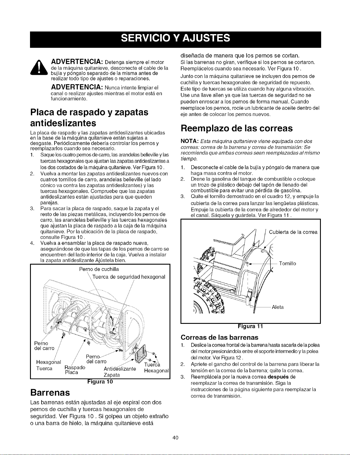
_ DVERTENClA: Detenga siempre el motor
de la maquina quitanieve, desconecte el cable de la
bujfa y p6ngalo separado de la misma antes de
realizar todo tipo de ajustes o reparaciones.
ADVERTENClA: Nunca intente limpiar el
canal o realizar ajustes mientras el motor esta en
funcionamiento.
Placa de raspado y zapatas
antideslizantes
La placa de raspado y las zapatas antideslizantes ubicadas
en la base de la maquina quitanieve estan sujetas a
desgaste. Periodicamente deberfa controlar los pernos y
reemplazarlos cuando sea necesario.
1. Saque loscuatro pernosde carro, las arandelas bellevilley las
tuercas hexagonales que ajustan laszapatas antideslizantes a
los dos costados de la maquina quitanieve. Ver Figura 10.
2. Vuelva a montar las zapatas antideslizantes nuevos con
cuatros tornillos de carro, arandelas belleville (el lado
conico va contra las zapatas antideslizantes) y las
tuercas hexagonales. Compruebe que las zapatas
antideslizantes esta.n ajustadas para que queden
parejas.
3. Para sacar la placa de raspado, saque la zapata y el
resto de las piezas metalicas, incluyendo los pernos de
carro, las arandelas belleville y las tuercas hexagonales
que ajustan la placa de raspado a la caja de la maquina
quitanieve. Por la ubicaci6n de la placa de raspado,
consulte Figura 10.
4. Vuelva a ensamblar la placa de raspado nueva,
asegurandose de que las tapas de los pernos de carro se
encuentren del lado interior de la caja. Vuelva a instalar
la zapata antideslizante AjQstela bien.
Perno de cuchilla
\\\Tuerca de seguridad hexagonal
\
\
Perno
del carro
Perno_
Ra_pado_del carro j
• ._,. uerca
Tuerca
Placa Anhdeshzante Hexagonal
Zapata
Figura 10
Barrenas
Las barrenas estan ajustadas al eje espiral con dos
pernos de cuchilla y tuercas hexagonales de
seguridad. Ver Figura 10. Si golpea un objeto extraSo
o una barra de hielo, la mb.quina quitanieve esta
diseSada de manera que los pernos se cortan.
Si las barrenas no giran, verifique si los pernos se cortaron.
Reemplacelos cuando sea necesario. Ver Figura 10.
Junto con la maquina quitanieve se incluyen dos pernos de
cuchilla y tuercas hexagonales de seguridad de repuesto.
Este tipo de tuercas se utiliza cuando hay alguna vibraci6n.
Use una Ilave allen ya que las tuercas de seguridad no se
pueden enroscar a los pernos de forma manual• Cuando
reemplace los pernos, rocfe un lubricante de aceite dentro del
eje antes de colocar los pernos nuevos.
Reemplazo de las correas
NOTA: Esta maquina quitanieve viene equipada con dos
correas: correa de la barrena y correa de transmisidn: Se
recomienda que ambas correas sean reemplazadas al mismo
tiempo.
1. Desconecte el cable de la bujfa y pongalo de manera que
haga masa contra el motor•
2. Drene la gasolina del tanque de combustible ocoloque
un trozo de plastico debajo del tapon de Ilenado del
combustible para evitar una perdida de gasolina.
3. Quite el tornillo demostrado en el cuadro 12, y empuje la
cubierta de la correa para lanzar las leng(Jetas plasticas.
Empuje la cubierta de la correa de alrededor del motor y
el canal• Saquela y guardela. Ver Figura 11.
Cubierta de la correa
/
Figura 11
Correas de las barrenas
1. Deslice lacorreafrontal de la barrena hasta sacarlade la polea
del motor presionandola entre el soporte intermedio y la polea
del motor• Ver Figura 12.
2. Apriete el gancho del control de la barrena para liberar la
tensi6n en lacorrea de la barrena; quite la correa.
3. Reemplacela por la nueva correa despuee de
reemplazar la correa de transmisi6n. Siga la
instrucciones de la pagina siguiente para reemplazar la
correa de transmision.
40
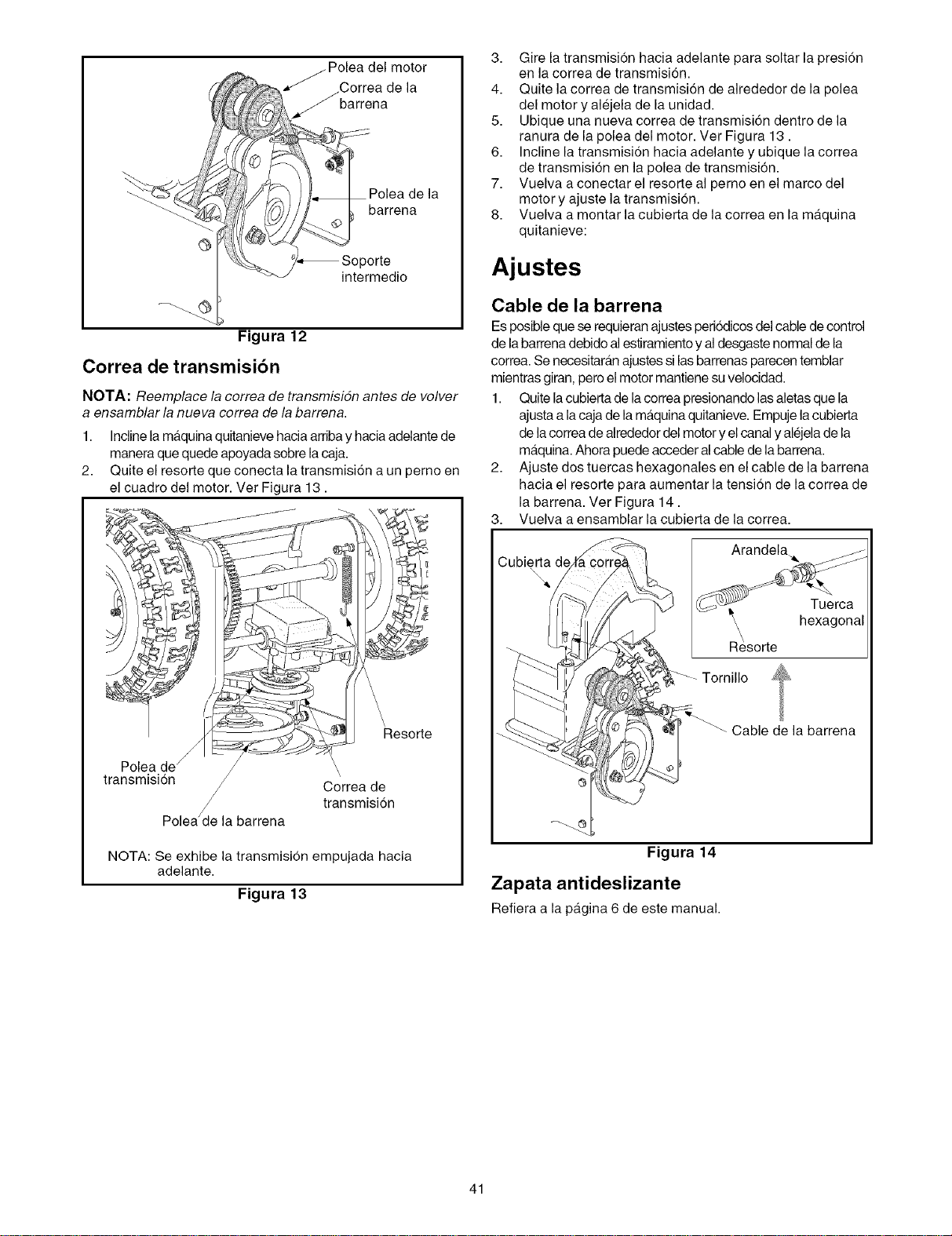
Figura 12
Correa de transmisibn
intermedio
NOTA: Reemplace la cerrea de transmisidn antes de velver
a ensamblarla nueva cerrea de la barrena.
1. Incline la maquina quitanieve haciaarriba y hacia adelante de
manera quequede apoyada sobre lacaja.
2. Quite el resorte que conecta la transmision a un perno en
el cuadro del motor. Ver Figura 13.
Resorte
Polea de
transmision
Polea_e la barrena
\
\
Correa de
transmision
NOTA: Se exhibe la transmision empujada hacia
adelante.
Figura 13
3. Gire la transmision hacia adelante para soltar la presi6n
en la correa de transmision.
4. Quite la correa de transmision de alrededor de la polea
del motor y alejela de la unidad.
5. Ubique una nueva correa de transmisi6n dentro de la
ranura de la polea del motor. Vet Figura 13.
6. Incline la transmision hacia adelante y ubique la correa
de transmision en la polea de transmisi6n.
7. Vuelva a conectar el resorte al perno en el marco del
motor y ajuste la transmision.
8. Vuelva a montar la cubierta de lacorrea en la maquina
quitanieve:
Ajustes
Cable de la barrena
Esposible quese requieran ajustes periodicos delcable de control
de labarrena debido alestiramiento y al desgaste normal de la
correa. Se necesitaran ajustessi las barrenas parecen temblar
mientras giran, pero el motor mantiene suvelocidad.
1. Quite lacubierta de la correa presionando las aletas que la
ajusta a la caja de la maquina quitanieve. Empuje la cubierta
de lacorrea de alrededor del motor y el canal y alejela de la
maquina. Ahora puede acceder al cable de la barrena.
2. Ajuste dos tuercas hexagonales en el cable de la barrena
hacia el resorte para aumentar la tension de lacorrea de
la barrena. Ver Figura 14.
3. Vuelva a ensamblar la cubierta de la correa.
Cubierta de
hexagonal
_-- Tornillo
Cable de la barrena
Figura 14
Zapata antideslizante
Refiera a la pagina 6 de este manual.
41
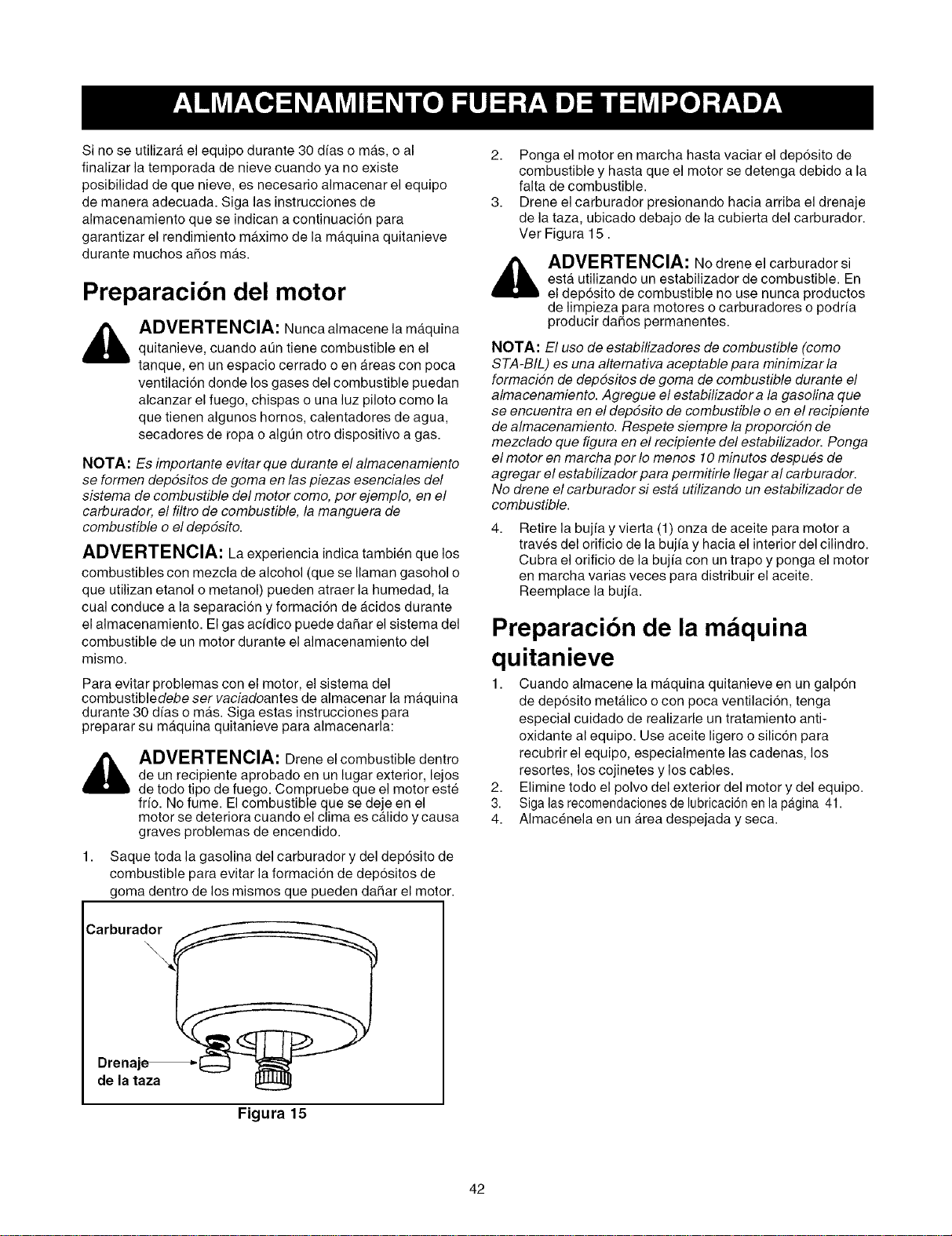
Sinoseutilizaraelequipodurante30dfasomas,oal
finalizarlatemporadadenievecuandoyanoexiste
posibilidaddequenieve,esnecesarioalmacenarelequipo
demaneraadecuada.Sigalasinstruccionesde
almacenamientoqueseindicanacontinuaci6npara
garantizarelrendimientomaximodelamaquinaquitanieve
durantemuchosaSosmas.
Preparacibn del motor
ADVERTENCIA: Nunca almacene la maquina
quitanieve, cuando at]n tiene combustible en el
tanque, en un espacio cerrado o en Areas con poca
ventilacidn donde los gases del combustible puedan
alcanzar el fuego, chispas o una luz piloto como la
que tienen algunos hornos, calentadores de agua,
secadores de ropa o algt]n otro dispositivo a gas.
NOTA: Es importante evitar que durante el almacenamiento
se formen depdsitos de goma en las piezas esenciales del
sistema de combustible del motor como, por ejemplo, en el
carburador, el filtro de combustible, la manguera de
combustible o eldepdsito.
ADVERTENCIA: La experiencia indica tambien que los
combustibles con mezcla de alcohol (que se Ilaman gasohol o
que utilizan etanol o metanol) pueden atraer la humedad, la
cual conduce a la separacion y formaci6n de acidos durante
el almacenamiento. El gas acfdico puede daSar el sistema del
combustible de un motor durante el almacenamiento del
mismo.
Para evitar problemas con el motor, el sistema del
combustibledebe ser vaciadoantes de almacenar la maquina
durante 30 d[as o mas. Siga estas instrucciones para
preparar su maquina quitanieve para almacenarla:
_ ADVERTENCIA: Drene elcombustible dentro
de un recipiente aprobado en un lugar exterior, lejos
de todo tipo de fuego. Compruebe que el motor este
fifo. No fume. El combustible que se deje en el
motor se deteriora cuando el clima es calido y causa
graves problemas de encendido.
1. Saque toda la gasolina del carburador y del dep6sito de
combustible para evitar la formacion de depositos de
goma dentro de los mismos que pueden dahar el motor.
Carburado__
Drenaje_ _:::_
de la taza
Figura 15
2. Ponga el motor en marcha hasta vaciar el dep6sito de
combustible y hasta que el motor se detenga debido a la
falta de combustible.
3. Drene el carburador presionando hacia arriba el drenaje
de la taza, ubicado debajo de la cubierta del carburador.
Ver Figura 15.
_ ADVERTENCIA: No drene el carburador si
esta utilizando un estabilizador de combustible. En
el dep6sito de combustible no use nunca productos
de limpieza para motores o carburadores o podrfa
producir daSos permanentes.
NOTA: El uso de estabilizadores de combustible (como
STA-BIL) es una altemativa aceptable para minimizar la
formacidn de depdsitos de goma de combustible durante el
almacenamiento. Agregue el estabilizador a la gasolina que
se encuentra en el depdsito de combustible o en el recipiente
de almacenamiento. Respete siempre la proporcidn de
mezclado que figura en el recipiente del estabilizador. Ponga
el motor en marcha por Io menos 10 minutos despu#s de
agregar el estabilizador para permitirle flegar al carburador.
No drene el carburador siesta utilizando un estabilizador de
combustible.
4,
Retire la bujfa y vierta (1) onza de aceite para motor a
traves del orificio de la bujia y hacia el interior del cilindro.
Cubra el orificio de la bujfa con un trapo y ponga el motor
en marcha varias veces para distribuir el aceite.
Reemplace la bujfa.
Preparacibn de la m quina
quitanieve
1. Cuando almacene la maquina quitanieve en un galpon
de deposito metalico o con poca ventilacion, tenga
especial cuidado de realizarle un tratamiento anti-
oxidante al equipo. Use aceite ligero o silicon para
recubrir el equipo, especialmente las cadenas, los
resortes, los cojinetes y los cables.
2. Elimine todo el polvo del exterior del motor y del equipo.
3. Siga las recomendaciones de lubricaci6n en lapagina 41.
4. Almacenela en un Area despejada y seca.
42
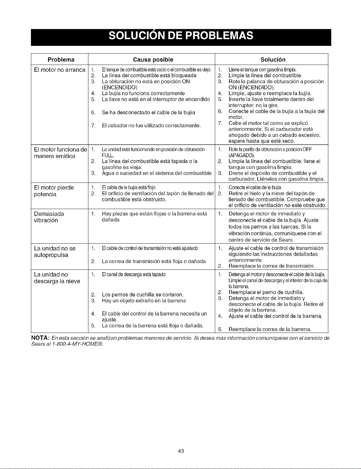
Problema Causa posible Solucibn
El motor no arranca
1. Eltanquedecombustibleestavaciooelcombustibleesviejo
2. La Ifnea del combustible esta bloqueada
3. La obturaci6n no esta en posicion ON
(ENCENDIDO)
4. La bujfa no funciona correctamente
5. La Ilave no esta. en el interruptor de encendido
6,
7.
Se ha desconectado el cable de la bujfa
El motorfuncionade 1.
manera erratica
2.
3.
El motor pierde 1.
potencia 2.
Demasiada 1.
vibraci6n
La unidad no se 1.
autopropulsa
2.
La unidad no 1.
descarga la nieve
2.
3.
4.
5,
El cebador no fue utilizado correctamente.
Launidadestafuncionandoenposiciondeobturaci6n
FULL.
La Ifnea del combustible esta tapada o la
gasolina es vieja.
Agua o suciedad en el sistema del combustible
Elcabledelabujfaestaflojo
El orificio de ventilacion del tapon de Ilenado del
combustible esta.obstruido.
Hay piezas que estan flojas o la barrena esta
daSada
Elcabledecontroldetransmisi6nnoestaajustado
La correa de transmisidn esta floja o daSada
Elcanaldedescargaestatapado
Los pernos de cuchilla se cortaron.
Hay un objeto extraho en la barrena
El cable del control de la barrena necesita un
ajuste.
La correa de la barrena esta floja o dahada.
1. Lleneeltanquecongasolinalimpia.
2. Limpie la Ifnea del combustible.
3. Rote la palanca de obturaci6n a posici6n
ON (ENCENDIDO).
4. Limpie, ajuste o reemplace la bujfa.
5. Inserte la Ilave totalmente dentro del
interruptor; no la gire.
6. Conecte el cable de la bujfa a la bujfa del
motor.
7. Cebe el motor tal como se explic6
anteriormente. Si el carburador esta
ahogado debido a un cebado excesivo,
espere hasta que este seco.
1. Rotelaperilladeobturacionaposici6nOFF
(APAGADO).
2. Limpie la Ifnea del combustible; Ilene el
tanque con gasolina limpia.
3. Drene el dep6sito de combustible y el
carburador. Llenelos con gasolina limpia.
1. Conecteelcabledelabujfa.
2. Retire el hielo y la nieve del tapon de
Ilenado del combustible. Compruebe que
el orificio de ventilaci6n no este obstruido.
Detenga el motor de inmediato y
desconecte el cable de la bujia. Ajuste
todos los pernos y las tuercas. Si la
vibraci6n contint]a, comunfquese con el
centro de servicio de Sears.
1. Ajuste el cable de control de transmision
siguiendo las instrucciones detalladas
anteriormente.
2. Reemplace la correa de transmision.
1. Detengael motory desconecteel cabledela bujia.
Limpieel canaldedescargayel interiordelacajade
labarrena.
2. Reemplace el perno de cuchilla.
3. Detenga el motor de inmediatoy
desconecte el cable de la bujfa. Retire el
objeto de labarrena.
4. Ajuste el cable del control de la barrena.
5.
Reemplace la correa de la barrena.
NOTA: En esta seccidn se analizan problemas menores de servicio. Si desea mas informacidn comunfquese con el servicio de
Sears al 1-800-4-MY-HOME®.
43

Your Home
For repair-in your home-of all major brand appliances,
lawn and garden equipment, or heating and cooling systems,
no matter who made it, no matter who sold it! ..................
For the replacement parts, accessories and
owner's manuals that you need to do-it-yourself. ....................................
For Sears professional installation of home appliances
and items like garage door openers and water heaters. ..................
1-800-4-MY-H 0 ME® (1-800-469-4663)
oa,,an t, o, o,oht sodOaoada ..................
www.sears.com www.sears.ca
OurHome
For repair of carry-in items like vacuums, lawn equipment,
and electronics, call or go on-line for the location of your nearest
Sears Parts & Repair Center.
1-800-488-1222
Call anytime, day or night (U.S.A. only)
www.sears.com
To purchase a protection agreement (U.S.A.)
or maintenance agreement (Canada) on a product serviced by Sears:
1-800-827-6655 (U.S.A.) 1-800-361-6665 (Canada)
Pard pedir servicio de reparacien Au Canada pour service en frangais:
a domicilio, y para ordenar piezas. 1-800- LE- FOYER Mc
1-8 88-S U-HOGAR sM
(1-800-533-6937)
(1-888-784-6427) www.sears.ca .............................
SEARS
SM
® Registered Trademark / TMTrademark / Service Mark of Sears, Roebuck and Co.
TM SM
® Marca Registrada / Marca de F_brica / Marca de Servicio de Sears, Roebuck and Co.
MC MD
Marque de commerce / Marque d6pos6e de Sears, Roebuck and Co. ® Sears, Roebuck and Co.


