
Operator's Manual
Snow Thrower
3.8 Horsepower 4-Cycle Engine
21-inch Single Stage
Auger Propelled
Model536.885201
CAUTION: Before using this product,
read this manual and follow all of its
Safety Rules and Operating Instructions.
CRRFTSMRN °
Manual del usario
Quitanieves
de 21 pulgadas
3.8 caballos de fuerza (hp)
Monoetapico
Propulsado por barrena
Modelo 536.885201
PRECAUCION: Antes de usar este producto,
lea este manual y siga todas las reglas de
seguridad e instrucciones de operaci6n.
Sears, Roebuck and Co., Hoffman Estates, IL 60179 U.S.A.
F-011060M www.sears.com/craftsman

NnIL,'q:] ! =l(o]j[_o] _Innl=1_In_
WARRANTY STATEMENT ......
SAFETY RULES ...............
INTERNATIONAL SYMBOLS . ..
ASSEMBLY ...................
OPERATION ..................
MAINTENANCE ...............
SERVICE AND ADJUSTMENT ..
2 STORAGE .................... 23
3 TROUBLE SHOOTING CHART.. 24
5 REPAIR PARTS ............... 28
7 ENGINE REPAIR PARTS ....... 34
9 SPANISH (ESPAI_IOL) .......... 40
15 PARTS ORDERING/SERVICE ..
18 BACK COVER
LIMITED ONE-YEAR WARRANTY ON CRAFTSMAN SNOW THROWER
For one years from the date of purchase, when this Craftsman Snow thrower is maintained,
lubricated, and tuned up according to the operating and maintenance instructions in the
owner's manual, Sears will repair, free of charge, any defect in material or workmanship.
If this Craftsman Snow thrower is used for commercial or rental purposes, this warranty ap-
plies for only 90 days from the date of purchase.
This warranty does not cover the following:
Items which become worn during normal use, such as spark plugs, drive belts and shear
pins.
Repair necessary because of operator abuse or negligence, including bent crankshafts
and the failure to maintain the equipment according to the instructions contained inthe
owner's manual.
WARRANTY SERVICE IS AVAILABLE BY RETURNING THE CRAFTSMAN SNOW
THROWER TO THE NEAREST SEARS SERVICE CENTER/DEPARTMENT IN THE
UNITED STATES. THIS WARRANTY APPLIES ONLY WHILE THIS PRODUCT IS IN USE
IN THE UNITED STATES.
This warranty gives you specific legal rights, and you may also have other rights which may
vary from state to state.
Sears, Roebuck and Co., D817WA, Hoffman Estates. IL 60179
GENERAL RECOMMENDATIONS
The warranty on this snow thrower does
not cover items that have been sub-
jected to operator abuse or negligence.
To receive full value from the warranty,
the operator must maintain the snow
thrower as instructed in this manual.
Some adjustments will need to be made
periodically to properly maintain your
snow thrower.
All adjustments in the Service and Ad-
justments section of this manual must
be checked at least once each season.
F-011060M
PRODUCT SPECIFICATIONS
Horse Power: 3.8
Displacement: 10 cu. in.
Fuel Tank: 1 quart
Champion RJf 9LM
Spark Plug: Gap 0.030
NOTE: Engine horsepower ratings
may vary by engine adjustments,
manufacturing variances, altitude, at-
mospheric conditions, fuel and main-
tenance.

_lk OOK FOR THIS SYMBOL TO POINT OUT IMPORTANT SAFETY PRECAUTIONS.
IT MEANS-- ATTENTION!!! BECOME ALERT!!! YOUR SAFETY IS INVOLVED.
Engine Exhaust, some of its con-
stituents, and certain vehicle com-
ponents contain or emit chemicals
known to the State of California to
cause cancer and birth defects or
other reproductive harm.
Battery posts, terminals and re-
lated accessories contain lead
and lead compounds, chemicals
known to the State of California to
cause cancer and birth defects or
other reproductive harm. WASH
HANDS AFTER HANDLING.
d_lb WARNING: Always disconnect
the spark plug wire and place it
where it cannot make contact
with spark plug to prevent accidental
starting during: Preparation, Mainte-
nance, or Storage of you snow thrower.
IMPORTANT: Safety standards require oper=
ator presence controls to minimize the risk of in-
jury. Your snow thrower isequipped with such
controls. Do not attempt to defeat the function
of the operator presence control under any cir-
cumstances.
TRAINING
1. Read the operating and service instruction
manual carefully. Be thoroughly familiar
with the controls and the proper use of the
equipment. Know how to stop the unit and
disengage the controls quickly.
2. Never allow children to operate the equip=
merit. Never allow adults to operate the
equipment without proper instruction.
3. Keep the area of operation clear of all per-
sons, particularly small children and pets.
4. Exercise caution to avoid slipping or falling
especially when operating in reverse.
PREPARATION
1. Thoroughly inspect the area where the
equipment is to be used and remove all
doormats, sleds, boards, wires, and other
foreign objects.
F-011060M
2. Disengage all cIu[ches before starting the
engine (motor).
3. Do not operate the equipment without
wearing adequate winter outer garments.
Wear footwear that will improve footing on
slippery surfaces.
4. Handle fuel with care; it is highly flam-
mable.
a. Use an approved fuel container.
b. Never remove fuel tank cap or add fuel
to a running engine (motor) or hot en-
gine (motor).
c. Fill fuel tank outdoors with extreme
care. Never fill fuel tank indoors.
d. RepIace fuel cap securely and wipe up
spilled fuel.
Never store fuel or snow thrower with
fuel in the tank inside of a building
where fumes may reach an open flame
or spark.
f. Check fuel supply before each use, al-
lowing space for expansion as the heat
of the engine (motor) and/or sun can
cause fuel to expand.
5. For all units with electdc starting motors
use electric starting extension cords certi-
fied CSA!UL. Use only with a receptacle
that has been installed in accordance with
local inspection authodties.
6. Never attempt to make any adjustments
while the engine (motor) is running (except
when specifically recommended by manu-
facturer).
7. Let engine (motor) and snow thrower ad-
justto outdoor temperatures before starting
to clear snow.
8. Always wear safety glasses or eye shields
during operation or while performing an ad-
justment or repair to protect eyes from
foreign objects that may be thrown from the
snow thrower.
OPERATION
1. Do not operate this machine if you are tak-
ing drugs or other medication which can
cause drowsiness or affect your ability to
operate this machine,
2. Do not use this machine ifyou are mentally
or physically unable to operate this ma-
chine safely.

3. Donotputhandsorfeetnearorunderro-
tatingparts.Keepclearofthedischarge
openingatalltimes.
4. Exerciseextremecautionwhenoperating
onorcrossinggraveldrives,walksor
roads.Stayalertforhiddenhazardsor
traffic.
5. Afterstrikingaforeignobject,stoptheen-
gine(motor),removethewirefromthe
sparkplug,thoroughlyinspectsnow
throwerforanydamage,andrepairthe
damagebeforerestartingandoperating
thesnowthrower.
6. Iftheunitshouldstarttovibrateabnormal-
Iy,stoptheengine(motor)andcheckim-
mediatelyforthecause.Vibrationis
generallyawarningoftrouble.
7. Stoptheengine(motor}wheneveryou
leavetheoperatingposition,beforeun-
cloggingtheauger/impellerhousingordis-
chargechuteandwhenmakingany
repairs,adjustments,orinspections.
8. Whencleaning,repairing,orinspecting,
makecertaintheauger/impellerandall
movingpartshavestoppedandallcontrols
aredisengaged.Disconnectthesparkplug
wireandkeepthewireawayfromthespark
plugtopreventaccidentalstarting.
9. Takeallpossibleprecautionswhenleaving
thesnowthrowerunattended.Disengage
theauger/impellerandstoptheengine
(motor).
10.Donotruntheengine(motor)indoors,ex-
ceptwhenstartingtheengine(motor)and
fortransportingthesnowthrowerinorout
ofthebuilding.Opentheoutsidedoors;ex-
haustfumesaredangerous(containing
CARSONMONOXIDE,anODORLESS
andDEADLYGAS).
11.Donotclearsnowacrossthefaceof
slopes.Exerciseextremecautionwhen
changingdirectiononslopes.Donotat-
tempttoclearsteepslopes.
12.Neveroperatethesnowthrowerwithout
properguards,platesorothersafetypro-
tectivedevicesinplace.
13.Neveroperatethesnowthrowernearen-
closures,automobiles,windowwells,
drop-offs,andthelikewithoutproperad-
justmentofthesnowdischargeangle.
Keepchildrenandpetsaway.
14.Donotoverloadthemachinecapacityby
attemptingtoclearsnowattoofastarate.
15.Neveroperatethemachineathightrans-
portspeedsonslipperysurfaces.Lookbe-
hindandusecarewhenbackingup.
16.Neverdirectdischargeatbystandersor
allowanyoneinfrontoftheunit.
17.Disengagepowertothecollector/impeller
whensnowthroweristransportedornotin
use,
18.Useonlyattachmentsandaccessoriesap-
provedbytheman_acturerofthesnow
thrower.
19.Neveroperatethesnowthrowerwithout
goodvisibilityorlight.Alwaysbesureof
yourfootingandkeepafirmholdonthe
handles.Walk;neverrun.
20.Donotover-reach.Keepproperfooting
andbalanceata]Itimes.
21.Donotattempttousesnowthrowerona
roof.
MAINTENANCE AND STORAGE
1. Check bolts at frequent intervals for proper
tightness to be sure the equipment is in
safe working condition.
2. Never store the snow thrower with fuel in
the tank inside a building where ignition
sources are present such as hot water and
space heaters, clothes dryers, and the like.
Allow the engine (motor) to cool before
storing in any enclosure.
3. Always refer to operator's guide instruc-
tions for important details if the snow
thrower is to be stored for an extended
period.
4. Maintain or replace safety and instruction
labels, as necessary.
5. Run the snow thrower a few minutes after
throwing snow to prevent freeze-up of the
auger/impeller.
_IL WARNING: This snow thrower is
for use on sidewalks, driveways
and other ground level surfaces.
Caution should be exercised while using on
steep sloping surfaces. DO NOT USE
SNOW THROWER ON SURFACES ABOVE
GROUND LEVEL such as roofs of resi-
dences, garages, porches or other such
structures or buildings.
F-011060M 4
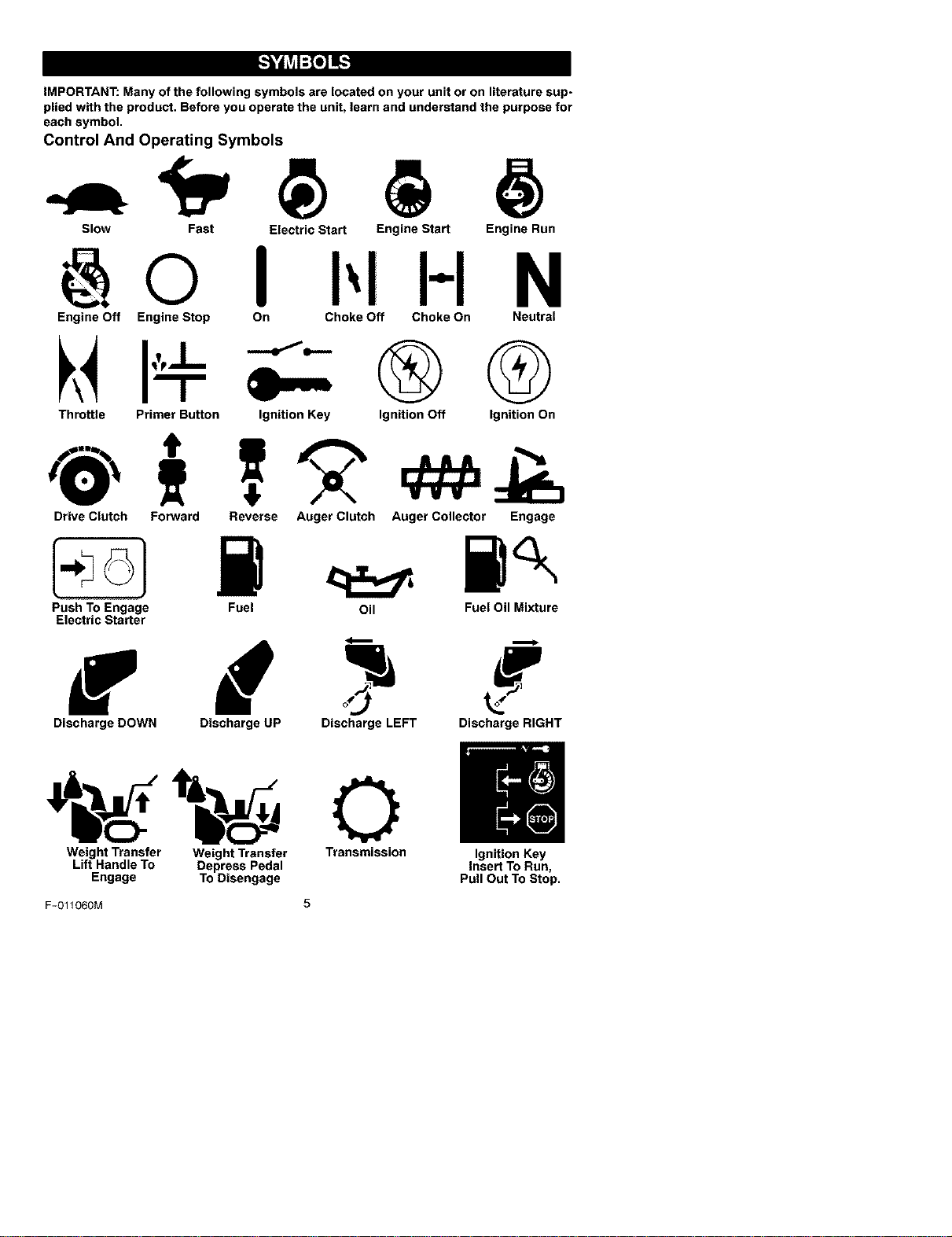
IMPORTANT: Many of the following symbols are located on your unit or on literature sup-
plied with the product. Before you operate the unit, learn and understand the purpose for
each symbol.
Control And Operating Symbols
Slow Fast Electric Start Engine Start Engine Run
H N
Engine Off Engine Stop On Choke Off Choke On Neutral
Throttle Primer Button Ignition Key
®Q
Ignition Off Ignition On
Drive Clutch Forward Reverse Auger Clutch Auger Collector Engage
Push To Engage
Electric Starter
Fuel Oil Fuel Oil Mixture
f d
Discharge DOWN Discharge UP Discharge LEFT Discharge RIGHT
Weight Transfer Weight Transfer Transmission Ignition Key
Lift Handle To Depress Pedal Insert To Run,
Engage To Disengage Pull Out To Stop.
F-O11060M 5
Safety Warning Symbols
DANGER
Thrown Objects.
Keep Bystanders Away.
IMPORTANT
Read Owner's Manual
Before Operating
This Machine.
DANGER
Thrown Objects.
Keep Bystanders Away.
DANGER
Avoid Injury From
Rotating Auger. Keep
Hands, Feet And
Clothing Away.
WARNING
DANGER
Stop The Engine
Before Unclogging
Discharge Chute!
WARNING
Hot Surface
STOP
F-O11060M 6
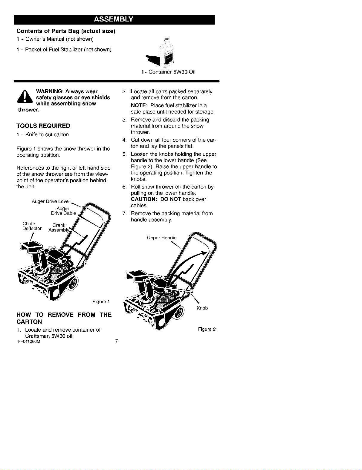
Contents of Parts Bag (actual size)
1 - Owner's Manual (notshown)
1 - Packet of Fuel Stabilizer (not shown)
1- Container 5W30 Oil
,_ WARNING: Always wearsafety glasses or eye shields
while assembling snow
thrower.
TOOLS REQUIRED
1 - Knife tocut carton
Figure 1 shows the snow thrower in the
operating position.
References to the right or left hand side
of the snow thrower are from the view-
point of the operator's position behind
the unit.
Auger Drive Lever _.
Auger
Drive Cable
Chute Crank
Deflector
Figure 1
HOW TO REMOVE FROM THE
CARTON
1. Locate and remove container of
Craftsman 5W30 oil.
F-011060M
2,
3,
4.
5.
6,
7,
Locate all parts packed separately
and remove from the carton.
NOTE: Place fuel stabilizer in a
safe place until needed for storage.
Remove and discard the packing
material from around the snow
thrower.
Cut down all four corners of the car-
ton and lay the panels flat.
Loosen the knobs holding the upper
handle to the lower handle (See
Figure 2). Raise the upper handle to
the operating position. Tighten the
knobs.
Roll snow thrower off the carton by
pulling on the lower handle.
CAUTION: DO NOT back over
cables.
Remove the packing material from
handle assembly.
Knob
Figure 2

_" CHECKLIST
Before you operate your new snow
thrower, to ensure that you receive the
best performance and satisfaction from
this quality product, please review the
following checklist:
_' All assembly instructions have been
completed.
_' The discharge chute rotates freely.
_' No remaining loose parts in carton.
While learning how to use your snow
thrower, pay extra attention to the fol-
lowing important items:
_' Engine oil is at proper level.
_' Make sure gas tank is filled properly
with clean, fresh, unleaded gasoline.
_' Become familiar with all controls-
their location and function. Operate
controls before starting engine.
F-011060M 8
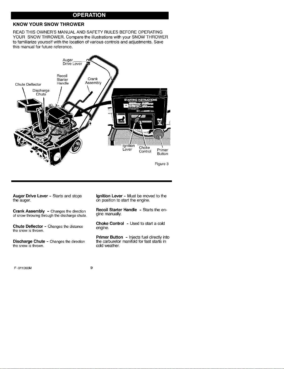
KNOW YOUR SNOW THROWER
READ THIS OWNER'S MANUAL AND SAFETY RULES BEFORE OPERATING
YOUR SNOW THROWER. Compare the illustrations with your SNOW THROWER
to familiarize yourself with the location of various controls and adjustments. Save
this manual for future reference.
Drive Lever
Recoil
Starter
Chute Deflector Handle
Discharge
Chute
Ignition
Lever Choke
Cont_I
Primer
Bu_on
Figure 3
Auger Drive Lever- Starts and stops
the auger.
Crank Assembly - Changesthe direction
of snowthrowingthroughthe dischargechLOe,
Chute Deflector - Changes the distance
the snow isthrown.
Discharge Chute - Changesthe direction
the snow isthrown.
Ignition Lever - Must be moved to the
on position to start the engine.
RecoilStarter Handle - Startstheen-
gine manually.
Choke Control - Used to start a cold
engine.
Primer Button - Injects fuel directly into
the carburetor manifold for fast starts in
cold weather.
F-011060M 9
The operation of any snow thrower can
result in foreign objects being thrown
into the eyes, which can result in se-
vere eye damage. Always wear safety
glasses or eye shields while operating
the snow thrower.
We recommend standard safety
glasses or a wide vision safety mask for
over your glasses.
,_ WARNING: Read Owner's
Manual before operating
machine. Never direct dis-
charge toward bystanders stop the
engine before unclogging discharge
chute or auger housing and before
leaving the machine.
TO STOP YOUR
SNOW THROWER
1. To stop throwing snow, release the
auger drive lever. See Figure 3.
NOTE: Ifthe snow thrower contin-
ues to slowly move forward, see
"How To Adjust The Auger Control
Cable" in the Service And Adjust-
ment Section.
2. To stop the engine, move the igni-
tion lever to the off position.
TO CONTROL SNOW DISCHARGE
1. Turn the chute control rod to set the
direction of the snow throwing.
2. Loosen the wing knob on the chute
deflector and move the deflector to
set the distance. Move the deflector
(Up) for more distance, (Down) for
less distance. Then tighten the
wing knob (See Figure 4).
Deflector Down Deflector Up
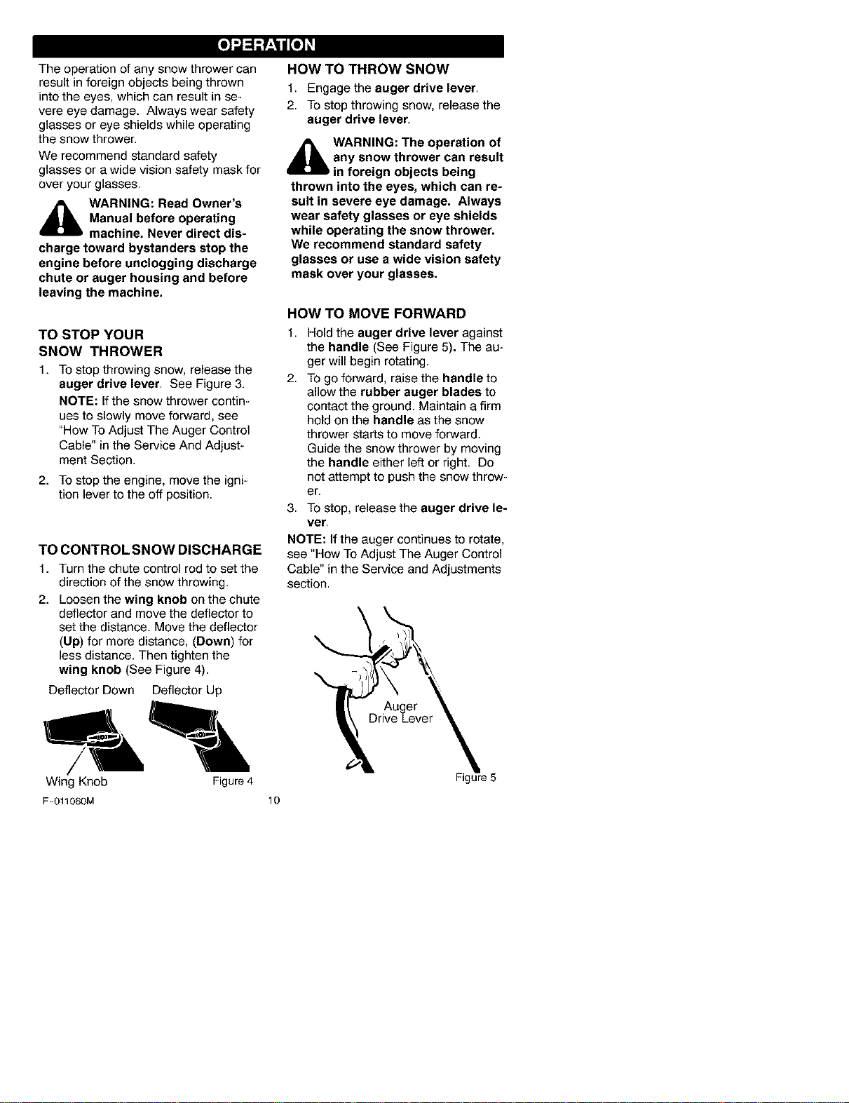
HOW TO THROW SNOW
1. Engage the auger drive lever.
2. To stop throwing snow, release the
auger drive lever.
,_ WARNING: The operation of
any snow thrower can result
in foreign objects being
thrown into the eyes, which can re-
sult in severe eye damage. Always
wear safety glasses or eye shields
while operating the snow thrower.
We recommend standard safety
glasses or use a wide vision safety
mask over your glasses.
HOW TO MOVE FORWARD
1,
2.
Hold the auger drive lever against
the handle (See Figure 5). The au-
ger will begin rotating.
To go forward, raise the handle to
allow the rubber auger blades to
contact the ground. Maintain a firm
hold on the handle as the snow
thrower starts to move forward.
Guide the snow thrower by moving
the handle either left or right. Do
not attempt to push the snow throw-
er.
3. To stop, release the auger drive le-
ver.
NOTE: If the auger continues to rotate,
see "How To Adjust The Auger Control
Cable" in the Service and Adjustments
section.
Wing Knob Figure 4
F-011060M 10
Figure 5
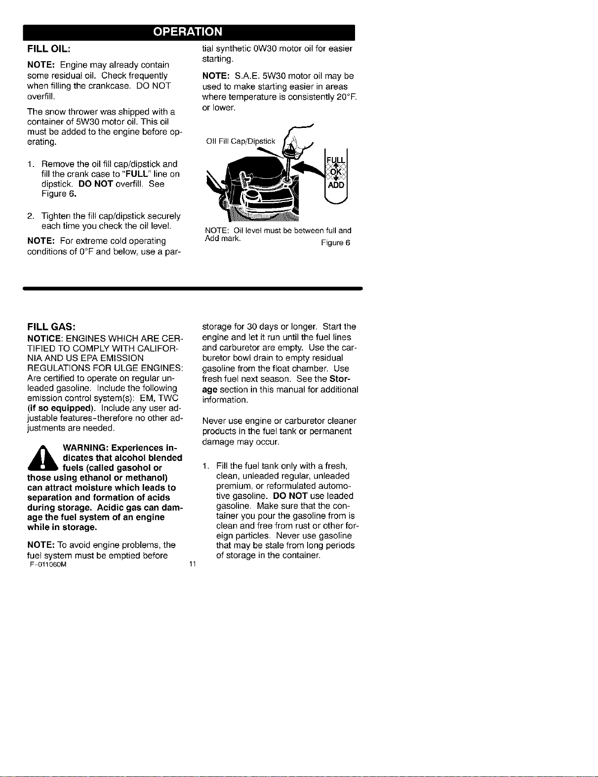
FILL OIL:
NOTE: Engine may already contain
some residual oil. Check frequently
when filling the crankcase. DO NOT
overfill.
The snow thrower was shipped with a
container of 5W30 motor oil. This oil
must be added to the engine before op-
erating.
1. Remove the oil fill cap/dipstick and
fill the crank case to "FULL" line on
dipstick. DO NOT overfill. See
Figure 6.
2. Tighten the fill cap/dipstick securely
each time you check the oil level.
NOTE: For extreme cold operating
conditions of 0°F and below, use a par-
tial synthetic 0W30 motor oil for easier
starting.
NOTE: S.A.E. 5W30 motor oil may be
used to make starting easier in areas
where temperature is consistently 20°E
or lower.
OII Fill Cap/Dipstick
NOTE: Oil level must be behNeen full and
Add mark.
Figure 6
FILL GAS:
NOTICE: ENGINES WHICH ARE CER-
TIFIED TO COMPLY WITH CALIFOR-
NIA AND US EPA EMISSION
REGULATIONS FOR ULGE ENGINES:
Are certified to operate on regular un-
leaded gasoline. Includethe following
emission control system(s): EM, TWC
(if so equipped). Include any user ad-
justable features-therefore no other ad-
justments are needed.
_lb WARNING: Experiences in-
dicates that alcohol blended
fuels (called gasohol or
those using ethanol or methanol)
can attract moisture which leads to
separation and formation of acids
during storage. Acidic gas can dam-
age the fuel system of an engine
while in storage.
NOTE: To avoid engine problems, the
fuel system must be emptied before
F-011060M
storage for 30 days or longer. Start the
engine and let it run until the fuel lines
and carburetor are empty. Use the car-
buretor bowl drain to empty residual
gasoline from the float chamber. Use
fresh fuel next season. See the Stor-
age section in this manual for additional
information.
Never use engine or carburetor cleaner
products in the fuel tank or permanent
damage may occur.
11
1,
Fill the fuel tank only with a fresh,
clean, unleaded regular, unleaded
premium, or reformulated automo-
tive gasoline. DO NOT use leaded
gasoline. Make sure that the con-
tainer you pour the gasoline from is
clean and free from rust or other for-
eign particles. Never use gasoline
that may be stale from long periods
of storage in the container.
_lb ARNING: Gasoline is flam-
mable. Always use caution
when handling or storing
gasoline.
Do not fill fuel tank while snow
thrower is running, when it is hot, or
when snow thrower is in an en-
closed area.
Keep away from open flame or an
electrical spark and do not smoke
while filling the fuel tank.
Never fill the tank completely. Fill
the tank to within 1/4"-1/2" from the
top to provide space for expansion
of fuel.
Always fill fuel tank outdoors and
use a funnel or spout to prevent
spilling.
Make sure to wipe up any spilled
fuel before stating the engine.
Store gasoline in a clean, approved
container and keep the cap in place
on the container.
BEFORE STARTING THE ENGINE
1. Before you service or start the en-
gine, familiarize yourself with the
snow thrower. Be sure you under-
stand the function and location of all
controls.
2. Be sure that all fasteners are tight.
3. Before starting the engine, make
sure all controls operate correctly.
COLD START
1. Move the ignition lever to the on
position.
2. Make sure the auger drive lever is
in the disengaged (RELEASED)
position.
3. Move the choke control to the full
choke position.
4. Push the primer button while cov-
ering the vent hole as follows: Re-
move finger from primer button
between primes.
Do not prime if temperature above
50 ° F (10° C).
Push two time if temperature is 50°
F (10° C) to 15°F (-10 ° C).
Push four times if temperature is
below 15° F (-10 ° C).
Push five time if temperature is be-
low0 ° F (-18 ° C).
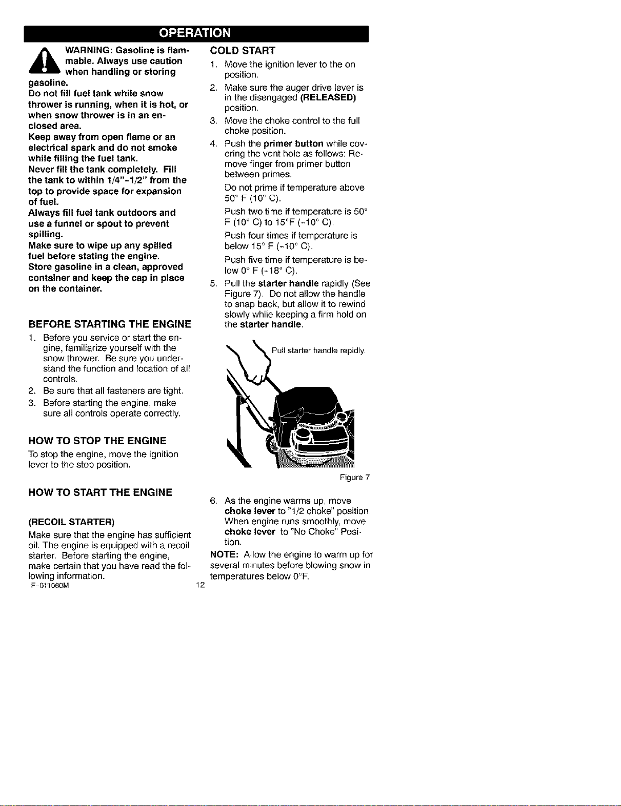
5. Pull the starter handle rapidly (See
Figure 7). Do not allow the handle
to snap back, but allow it to rewind
slowly while keeping a firm hold on
the starter handle.
Puil starter handle repidly.
HOW TO STOP THE ENGINE
To stop the engine, move the ignition
lever to the stop position.
HOW TO START THE ENGINE
(RECOIL STARTER)
Make sure that the engine has sufficient
oil. The engine is equipped with a recoil
starter. Before starting the engine,
make certain that you have read the fol-
lowing information.
F-011060M
Figure 7
12
6. As the engine warms up, move
choke lever to "1/2 choke" position.
When engine runs smoothly, move
choke lever to "No Choke" Posi-
tion.
NOTE: Allow the engine to warm up for
several minutes before blowing snow in
temperatures below 0°E
WARM START
If restarting a warm engine after a short
shutdown, leave choke at "OFF" and do
not push the primer button. If the en-
gine fails to start, follow the Cold Start
instructions.
FROZEN STARTER
Ifthe starter is frozen and will not turn
engine:
1. Pull as much rope out of the starter
as possible.
2. Release the starter handle and let it
snap back against the starter.
Ifthe engine still fails to start, repeat the
two previous steps until the engine
starts. Then continue with the direc-
tions for cold start.
To help prevent possible freeze-up of
recoil starter and engine controls, pro-
ceed as follows after each snow remov-
al job.
1. With the engine running, pull the
starter rope hard with a continuous
full arm stroke three or four times.
Pulling of starter rope will produce a
loud clattering sound. This is not
harmful to the engine or starter.
2. With the engine not running, wipe all
snow and moisture from the carbu-
retor cover in area of control levers.
Also move throttle control, choke
control, and starter handle several
times.
_lb WARNING: Never run en-
gine indoors or in enclosed,
poorly ventilated areas. En-
gine exhaust contains CARBON
MONOXIDE, AN ODORLESS AND
DEADLY GAS. Keep hands, feet,
hair and loose clothing away from
any moving parts on engine and
snow thrower.
The temperature of muffler and
nearby areas may exceed 150°1=.
Avoid these areas.
DO NOT allow children or young
teenagers to operate or be near
snow thrower while it is operating.
_lb ARNING: Do not attempt
to remove any item that may
become lodged in auger
without taking the following precau-
tions:
• Release auger drive lever.
• Move the ignition lever to the
stop position to stop the engine.
• Disconnect spark plug wire.
Do not place your hands in the
auger or discharge chute. Use a
pry bar.
SNOW THROWING TIPS
1. When the handle is raised, the au-
ger blades will engage the ground
and the snow thrower will move for-
ward. When the auger drive lever is
released, the auger blades will stop.
If the blades do not stop, see "How
To Adjust The Auger Drive Cable" in
the Service And Adjustment section.
2. Most efficient snow throwing is ac-
complished when the snow is re-
moved immediately after if falls.
3. For complete snow removal, slightly
overlap each previous path.
4. Whenever possible, discharge the
snow down wind.
F-011060M
13
5,
6,
The distance the snow will be dis-
charged can be adjusted by moving
the discharge chute deflector. Raise
the deflector for more distance or
lower the deflector for less distance.
In windy conditions, lower the chute
deflector to direct the discharged
snow close to the ground where it is
less likely to blow into unwanted
areas.
7. For safety and to prevent damage
to the snow thrower, keep the area
to be cleared free of stones, toys
and other foreign objects.
8. Do not use the auger propelling fea-
ture when clearing gravel or
crushedrockdriveways.Movethe
handledowntoslightlyraisetheau-
ger.
9. Theforwardspeedofthesnow
throwerisdependentonthedepth
andweightofthesnow.Experience
willestablishthemosteffective
methodofusingthesnowthrower
underdifferentconditions.
10.Aftereachsnowthrowingjob,allow
theenginetorunforafewminutes.
Thesnowandaccumulatedicewill
meltofftheengine.
11.Cleanthesnowthroweraftereach
use.
12.Removeice,snowanddebrisfrom
theentiresnowthrower.Flushwith
watertoremoveallsaltorother
chemicals.Wipesnowthrowerdry.
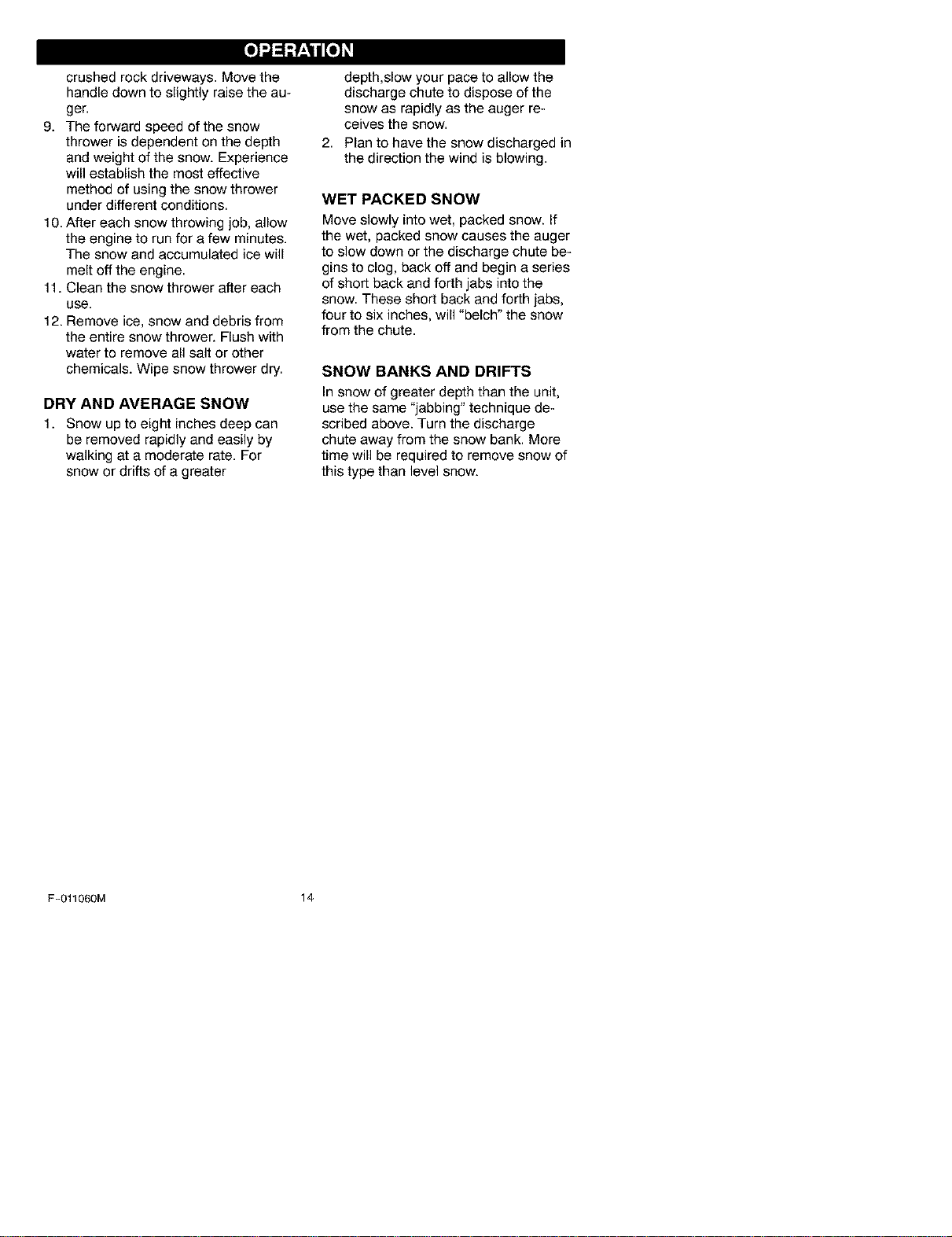
DRY AND AVERAGE SNOW
1. Snow up to eight inches deep can
be removed rapidly and easily by
walking at a moderate rate. For
snow or drifts of a greater
depth,slow your pace to allow the
discharge chute to dispose of the
snow as rapidly as the auger re-
ceives the snow.
2. Plan to have the snow discharged in
the direction the wind is blowing.
WET PACKED SNOW
Move slowly into wet, packed snow. If
the wet, packed snow causes the auger
to slow down or the discharge chute be-
gins to clog, back off and begin a series
of short back and forth jabs into the
snow. These short back and forth jabs,
four to six inches, will "belch" the snow
from the chute.
SNOW BANKS AND DRIFTS
In snow of greater depth than the unit,
use the same "jabbing" technique de-
scribed above. Turn the discharge
chute away from the snow bank. More
time will be required to remove snow of
this type than level snow.
F-O11060M 14
CUSTOMER RESPONSIBILITIES
SERVICERECORDS
Fillindatesasyou Before Every Every Every
completeregular Each 5 10 25 Each Before SERVICE
service. Use Often Hours Hours Hours SeasonStorage DATES
Check Engine Oil Level _/ _r _/ •
Change Engine Oil _/ _/
Tighten A_IScrews and I I I I I
Nuts
Check Spark Plug _/ _/
, , , , , , ,
Lubricate Chute Control .....
Flange
Drain Fuel ,/
CheckFuel _/ • I I I I I I
Check Auger Drive
_able Ad ustment
See Cab e Ad ustment _/
GENERAL RECOMMENDATIONS
The warranty on this snow thrower
does not cover items that have been
subjected to operator abuse or negli-
gence. To receive full value from the
warranty, the operator must maintain
the snow thrower as instructed inthis
manual.
Some adjustments will need to be
made periodically to properly maintain
your snow thrower.
All adjustments in the Service and Ad-
justments section of this manual
should be checked at least once each
season.
AFTER EACH USE
Check for any loose or damaged
parts.
Tighten any loose fasteners.
Check and maintain the auger.
Check controls to make sure they
are functioning properly.
If any parts are worn or damaged,
replace immediately.
Run the machine to clear the auger
of snow.
To prevent freezing of the auger or
controls, remove all snow and slush
from the snow thrower.
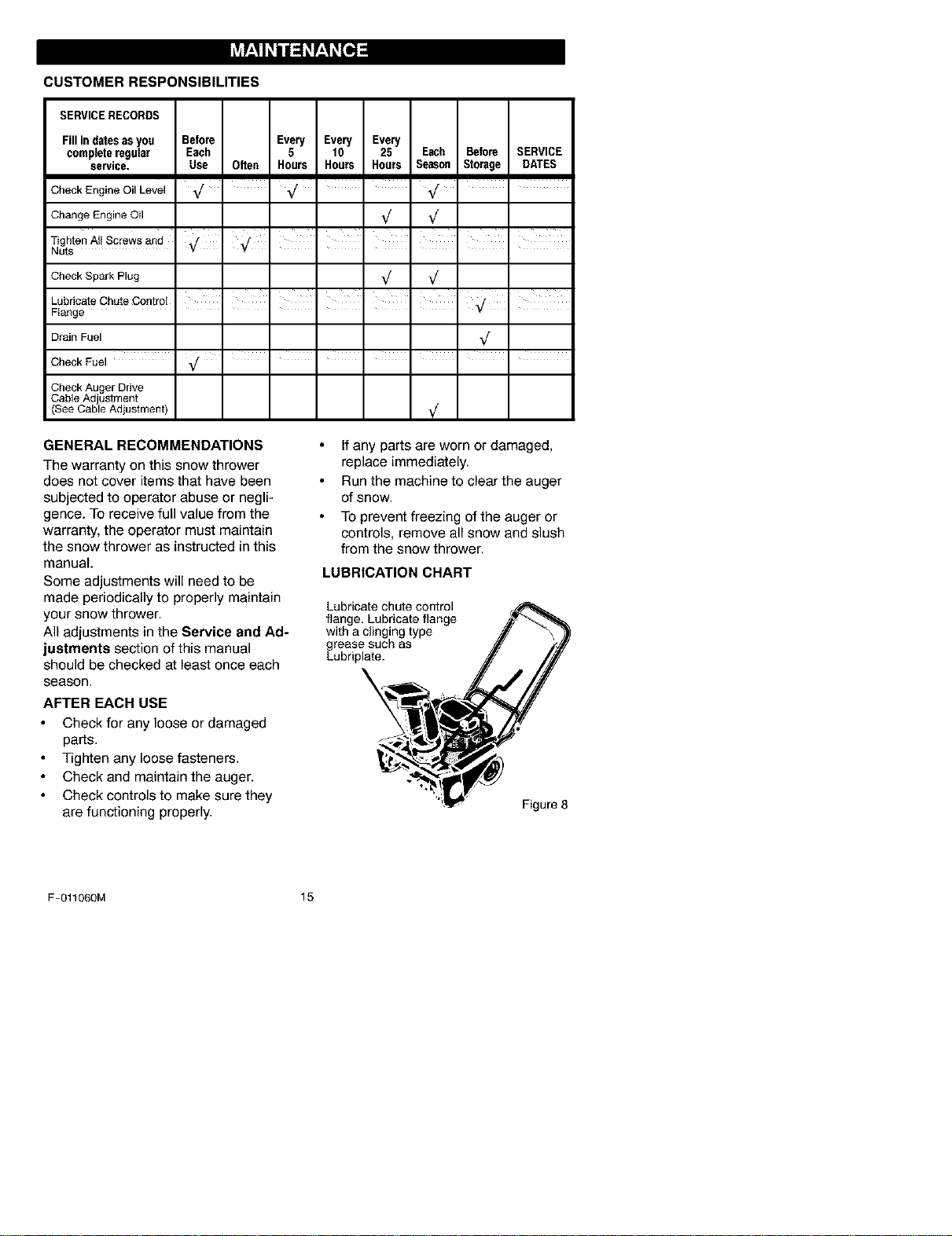
LUBRICATION CHART
Lubricate chute control
flange, Lubricate flange
with a clinging type
grease such as
Lubriplate.
Figure 8
F-Ot1060M 15
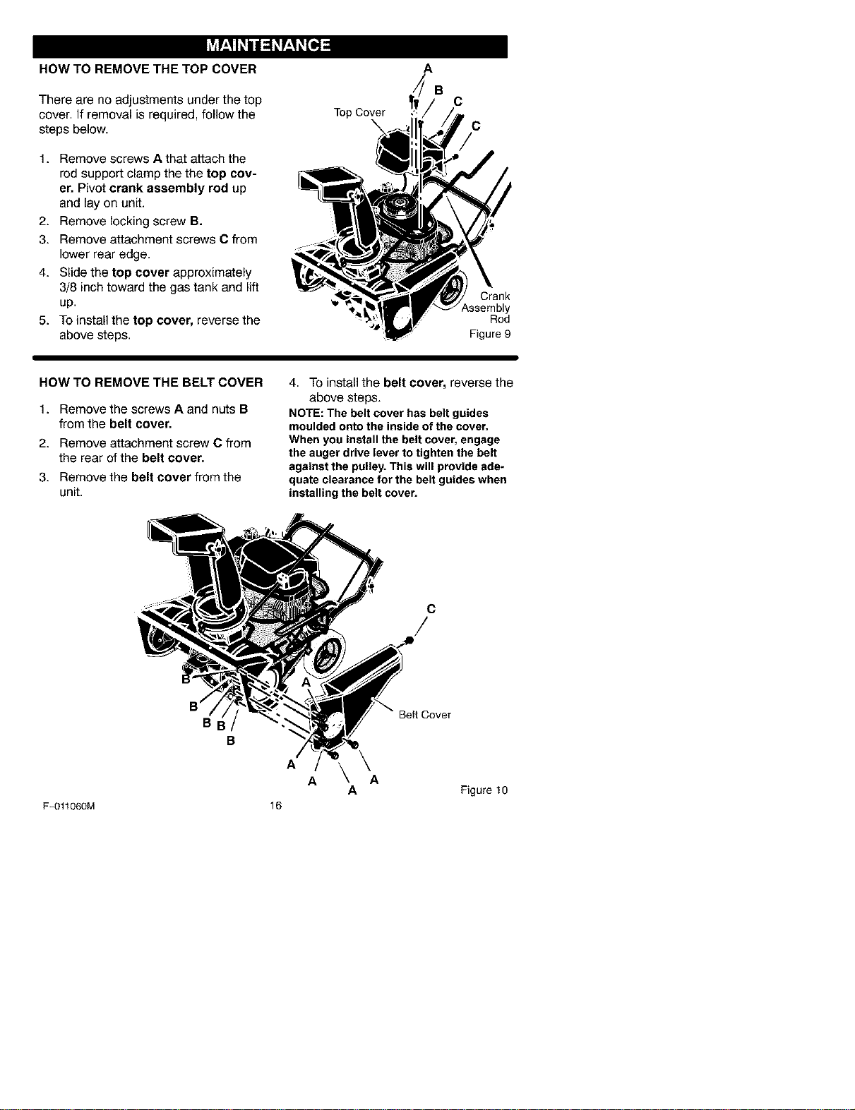
HOW TO REMOVE THE TOP COVER
There are no adjustments under the top
cover. If removal is required, follow the
steps below.
1. Remove screws A that attach the
rod support clamp the the top cov-
er, Pivot crank assembly rod up
and lay on unit.
2. Remove locking screw B.
3. Remove attachment screws C from
lower rear edge.
4. Slide the top cover approximately
3/8 inch toward the gas tank and lift
up.
5. To install the top cover, reverse the
above steps.
Top Cover
A
B
C
C
Crank
ssembly
Rod
Figure 9
HOW TO REMOVE THE BELT COVER
1. Remove the screws A and nuts B
from the belt cover,
2. Remove attachment screw C from
the rear of the belt cover,
3. Remove the belt cover from the
unit.
4. To install the belt cover, reverse the
above steps.
NOTE: The belt cover has belt guides
moulded onto the inside of the cover.
When you install the belt cover, engage
the auger drive lever to tighten the belt
against the pulley. This will provide ade-
quate clearance for the belt guides when
installing the belt cover.
C
F-01r060M
BI
B
A
16
Beit Cover
\
A A
A Figure10
ENGINE
LUBRICATION
Check the crankcase oil level before
starting the engine and after each five
(5) hours of continuous use. See
Figure 11. Add S.A.E. 5W30 motor oil
as needed. Tighten oil fill cap/dipstick
securely each time you check the oil
level.
Oll FillCap/Dipstick
NOTE: Oil levelmustbe between the
FULL and ADD mark.
Figure 11
Change the oil every twenty-five (25)
hours or at least once a year if the
snow thrower is not used for twenty-
five (25) hours.
HOW TO CHANGE THE ENGINE OIL
To change the engine oil, the engine
must be tilted forward and the oil
drained from the oil fill tube as follows.
1. Lift the rear of the snowthrower and
tilt the unit forward. In the correct
position, the snowthrower will be
setting on the front of the auger
housing.
2. Put an oil drain pan under the oil
fill tube (See Figure 12).
3,
4.
5.
Carefully remove the oil fill cap/dip-
stick. Oil will begin to flow into the
oil drain pan.
After all the oil has drained from the
engine, set the snowthrower in the
operating position.
Fill the engine with S.A.E. 5W30 oil.
Make sure the oil reaches the FULL
mark on the oil fill cap/dipstick. DO
NOT OVERFILL.
NOTE: For extreme cold operating
conditions of 0°F and below, use a par-
tial synthetic 0W30 motor oil for easier
starting.
SPARK PLUG
Check the spark plug every twenty-
five (25) hours. Replace the spark plug
if the electrodes are pitted or burned or
if the porcelain is cracked.
1,
2,
3.
Make sure the spark plug is clean.
Clean the spark plug by carefully
scraping the electrodes (do not
sand blast or use a wire brush).
Check the spark plug gap with a
feeler gauge and reset gap to 0.30"
if necessary. See Figure 13.
Before installing the spark plug,
coat the threads lightly with oil for
easy removal. Tighten the spark
plug to a torque of 15 foot-pounds.
Fill Tube
OII Drain
, Pan
Feeler Gauge
0.030"
Spark Plug
Figure 13
Figure 12
F-011060M 17
_lb WARNING: To prevent acci-
dental starting when making
any adjustments or repairs,
always disconnect the spark plug
wire and place it where it cannot
make contact with the spark plug.
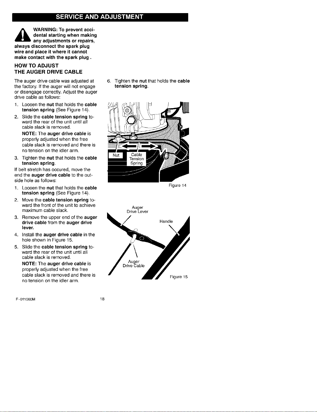
HOW TO ADJUST
THE AUGER DRIVE CABLE
The auger drive cable was adjusted at
the factory. If the auger will not engage
or disengage correctly. Adjust the auger
drive cable as follows:
1. Loosen the nut that holds the cable
tension spring (See Figure 14).
2. Slide the cable tension spring to-
ward the rear of the unit until all
cable slack is removed.
NOTE: The auger drive cable is
properly adjusted when the free
cable slack is removed and there is
no tension on the idler arm.
3. Tighten the nut that holds the cable
tension spring.
If belt stretch has occured, move the
end the auger drive cable to the out-
side hole as follows:
1. Loosen the nut that holds the cable
tension spring (See Figure 14).
2. Move the cable tension spring to-
ward the front of the unit to achieve
maximum cable slack.
3. Remove the upper end of the auger
drive cable from the auger drive
lever.
4. Install the auger drive cable in the
hole shown in Figure 15.
5. Slide the cable tension spring to-
ward the rear of the unit until all
cable slack is removed.
NOTE: The auger drive cable is
properly adjusted when the free
cable slack is removed and there is
no tension on the idler arm.
6. Tighten the nut that holds the cable
tension spring.
Auger
Drive Lever
Figure 14
Handle
\
Auger
Drive Cable
Figure 15
F-011060M 18
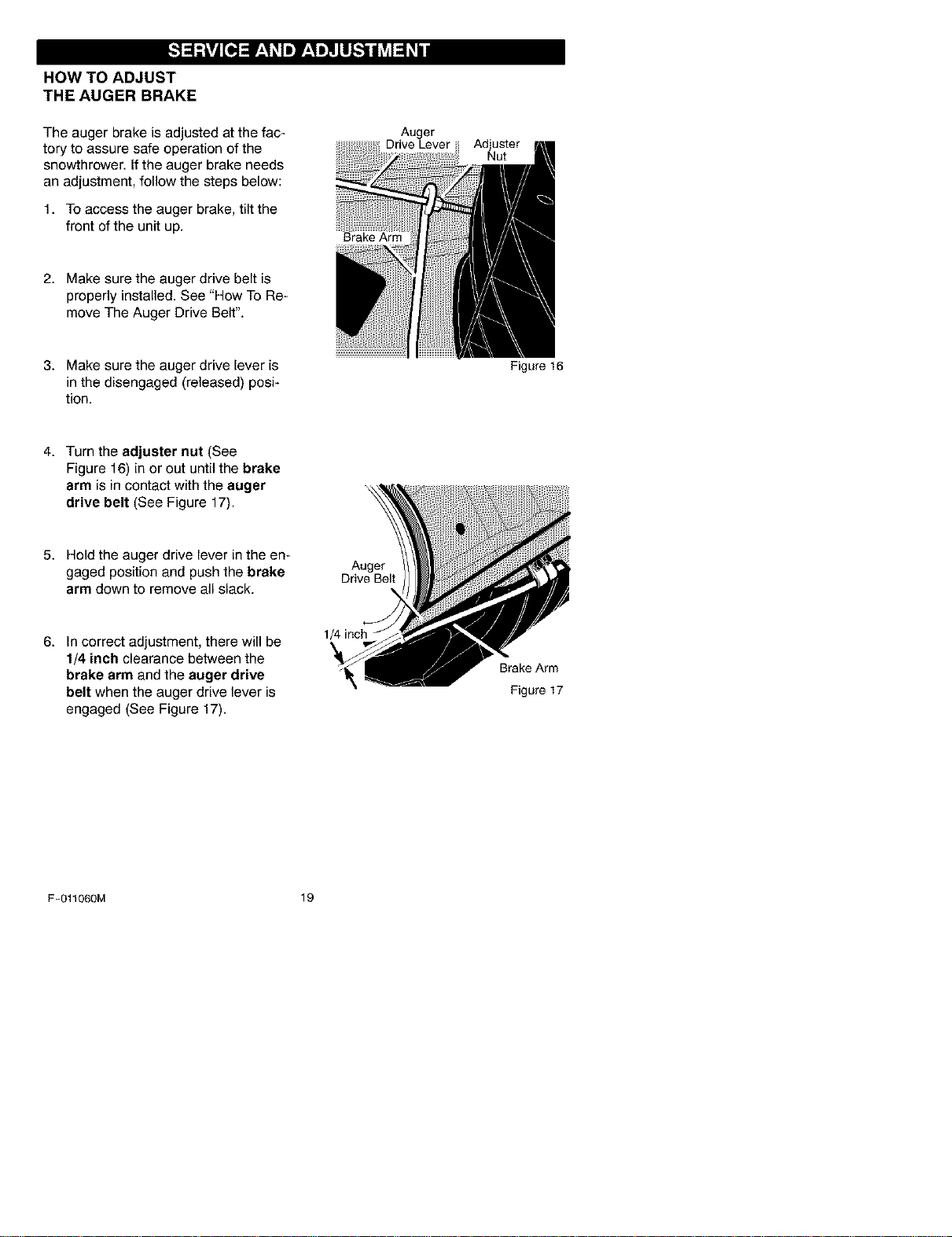
HOW TO ADJUST
THE AUGER BRAKE
The auger brake is adjusted at the fac-
tory to assure safe operation of the
snowthrower. If the auger brake needs
an adjustment, follow the steps below:
1. To access the auger brake, tilt the
front of the unit up.
2. Make sure the auger drive belt is
properly installed. See "How To Re-
move The Auger Drive Belt".
Auger
Drive Lever
Brake Arm
Adjuster
Nut
3. Make sure the auger drive lever is
in the disengaged (released) posi-
tion.
Figure 16
4. Turn the adjuster nut (See
Figure 16) in or out until the brake
arm is in contact with the auger
drive belt (See Figure 17).
5. Hold the auger drive lever in the en-
gaged position and push the brake
arm down to remove all slack.
Auger
Drive Belt
6. In correct adjustment, there will be
1/4 inch clearance between the
brake arm and the auger drive
belt when the auger drive lever is
engaged (See Figure 17).
1/4 inch
Brake Arm
Figure 17
F-011060M 19
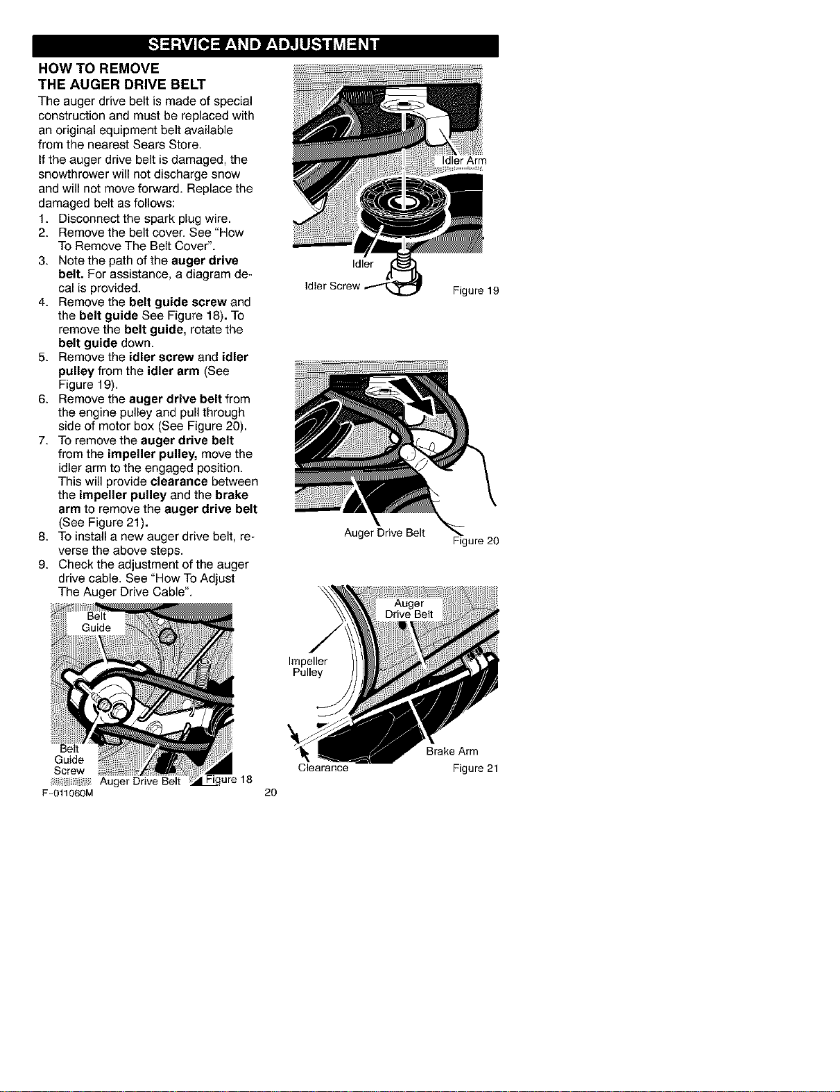
HOW TO REMOVE
THE AUGER DRIVE BELT
The auger drive belt is made of special
construction and must be replaced with
an original equipment belt available
from the nearest Sears Store.
Ifthe auger drive belt is damaged, the
snowthrower will not discharge snow
and will not move forward. Replace the
damaged belt as follows:
1. Disconnect the spark plug wire.
2. Remove the belt cover. See "How
To Remove The Belt Cover".
3. Note the path of the auger drive
belt. For assistance, a diagram de-
cal is provided.
4. Remove the belt guide screw and
the belt guide See Figure 18). To
remove the belt guide, rotate the
belt guide down.
5. Remove the idler screw and idler
pulley from the idler arm (See
Figure 19).
6. Remove the auger drive belt from
the engine pulley and pull through
side of motor box (See Figure 20).
7. To remove the auger drive belt
from the impeller pulley, move the
idler arm to the engaged position.
This will provide clearance between
the impeller pulley and the brake
arm to remove the auger drive belt
(See Figure 21).
8. To install a new auger drive belt, re-
verse the above steps.
9. Check the adjustment of the auger
drive cable. See "How To Adjust
The Auger Drive Cable".
Belt
Guide
Screw
Auger Drive Belt
F-011060M
ure 18
Idler
Idler Screw
Auger Drive Belt
Impeller
Pulley
Clearance
20
Idler Arm
Figure 19
Figure 20
Brake Arm
Figure 21
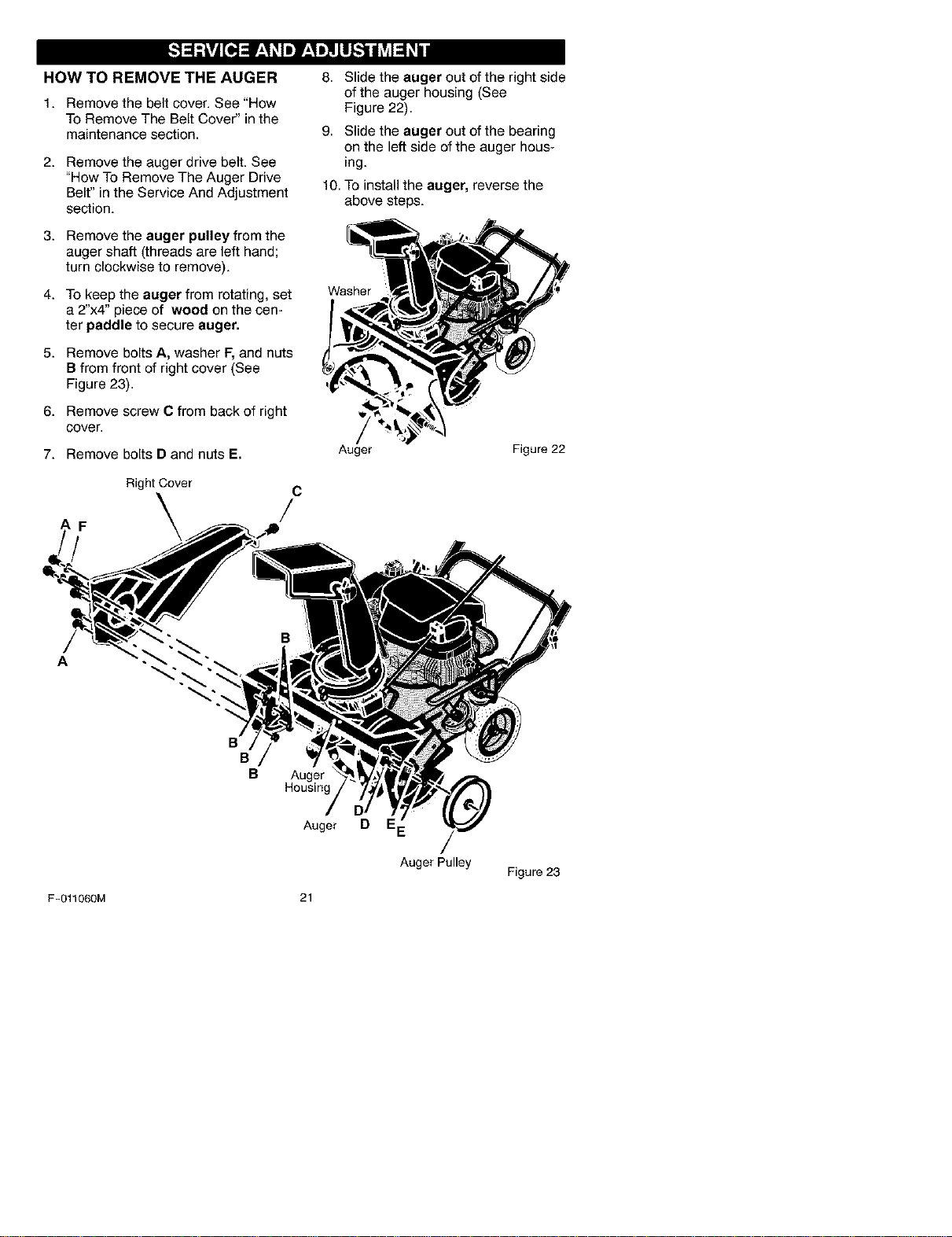
HOW TO REMOVE THE AUGER 8. Slide the auger out of the right side
of the auger housing (See
Figure 22).
1. Remove the belt cover. See "How
To Remove The Belt Cover" in the
maintenance section.
2. Remove the auger drive belt. See
"How To Remove The Auger Drive
Belt" in the Service And Adjustment
section.
3. Remove the auger pulley from the
auger shaft (threads are left hand;
turn clockwise to remove).
4. To keep the auger from rotating, set
a 2"x4" piece of wood on the cen-
ter paddle to secure auger,
5. Remove bolts A, washer F, and nuts
B from front of right cover (See
Figure 23).
6. Remove screw C from back of right
cover.
7. Remove bolts D and nuts E.
AF
Right Cover
C
/
9. Slide the auger out of the bearing
on the left side of the auger hous-
ing.
10. To install the auger, reverse the
above steps.
Washer
Auger Figure 22
A
F-011060M
B
B
B
Auger
Housing
Auger
21
D
Auger Pulley
Figure 23
TO ADJUST THE CARBURETOR
The carburetor is not adjustable. En-
gine performance should not be af-
fected at altitudes up to 7,000 feet. For
operation at higher elevations, contact
your nearest Sears Store.
IMPORTANT: Never tamper with the
engine governor, which is factory set for
proper engine speed. Over-speeding
the engine above the factory high
speed setting can be dangerous. If you
think the engine-governed high speed
needs adjusting, contact your nearest
Craftsman Store, which has the proper
equipment and experience to make any
necessary adjustments.
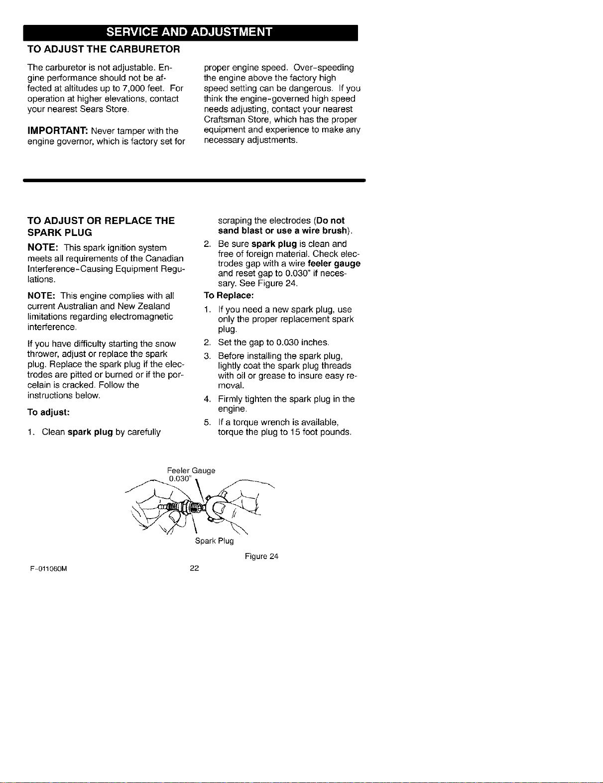
TO ADJUST OR REPLACE THE
SPARK PLUG
NOTE: This spark ignition system
meets all requirements of the Canadian
Interference-Causing Equipment Regu-
lations.
NOTE: This engine complies with all
current Australian and New Zealand
limitations regarding electromagnetic
interference.
Ifyou have difficulty starting the snow
thrower, adjust or replace the spark
plug. Replace the spark plug if the elec-
trodes are pitted or burned or if the por-
celain is cracked. Follow the
instructions below.
TO adjust:
1. Clean spark plug by carefully
scraping the electrodes (Do not
sand blast or use a wire brush).
2. Be sure spark plug is clean and
free of foreign material. Check elec-
trodes gap with a wire feeler gauge
and reset gap to 0.030" if neces-
sary. See Figure 24.
To Replace:
1. If you need a new spark plug, use
only the proper replacement spark
plug.
2. Set the gap to 0.030 inches.
3. Before installing the spark plug,
lightly coat the spark plug threads
with oil or grease to insure easy re-
moval.
4. Firmly tighten the spark plug in the
engine.
5. If a torque wrench is available,
torque the plug to 15 foot pounds.
Feeler Gauge
F-011060M
Spark Plug
Figure 24
22
_[b ARNING: Never store your
snow thrower indoors or in
an enclosed, poorly venti-
lated area. If gasoline remains in the
tank, fumes may reach an open
flame, spark or pilot light from a fur-
nace, water heater, clothes dryer,
cigarette, etc.
NOTE: To prevent engine damage (if
snow thrower is not used for more than
30 days) follow the steps below.
SNOW THROWER
1. Thoroughly clean the snow thrower.
2. Lubricate all lubrication points. See
the Maintenance section.
3. Be sure that all nuts, bolts and
screws are securely fastened. In-
spect all visible moving parts for
damage, breakage and wear. Re-
place if necessary.
4. Touch up all rusted or chipped paint
surfaces; sand lightly before paint-
ing.
5. Cover the bare metal parts of the
blower housing auger and the im-
peller with rust preventative, such
as a spray lubricant.
NOTE: A yearly checkup or tune-up by
a Sears service center is a good way of
ensuring that your snow thrower will
provide maximum performance for the
next season.
ENGINE
_lb ARNING: Drain the gaso-
line outdoors, away from
fire or flame.
Gasoline must be removed or treated to
prevent gum deposits from forming in
the fuel tank, filter, hose, and carburetor
during storage. Also, during storage al-
cohol blended gasoline that uses etha-
nol or methanol (sometimes called
gasohol) attracts water. It acts on the
gasoline to form acids which damage
the engine.
F-011060M
1,
2.
3,
4,
5.
TO remove gasoline, run the engine
until the fuel tank is empty and the
engine stops.
If you do not remove the gasoline,
use fuel stabilizer supplied with unit
or purchase Craftsman Fuel Stabi-
lizer No. 3550. Add fuel stabilizer to
any gasoline left in the tank to mini-
mize gum deposits and acids. If the
fuel tank is almost empty, mix stabi-
lizer with fresh gasoline in a sepa-
rate container and add some to the
fuel tank.
Always follow the instruction on the
stabilizer container. After the stabi-
lizer is added to the fuel tank, run
the engine at least ten minutes to
allow the mixture to reach the car-
buretor.
Change the engine oil.
Lubricate the piston/cylinder area.
First, remove the spark plug and
squirt a few drops of clean engine
oil into the spark plug hole. Next,
cover the spark plug hole with a rag
to absorb oil spray. Then, pull two or
three times on the recoil starter rope
to rotate the engine. Finally, install
the spark plug and attach the spark
plug wire.
23
OTHER
1. If possible, store your snow thrower
indoors and cover it to give protec-
tion from dust and dirt.
2, If the machine must be stored out-
doors, block up the snow thrower to
be sure the entire machine is off the
ground.
3. Cover the snow thrower with a suit-
able protective cover that does not
retain moisture. Do not use plastic.
IMPORTANT: Never cover snow
thrower while engine and exhaust areas
are still warm.
TROUBLE CORRECTION
Difficult starting Replacespark plug.
CAUSE
Defectivespark plug.
Wateror dirt in fuel system.
Use carburetor bowl drain to
flush and refill with fresh fuel.
Engine rune erratic Blocked fuel line, empty gas Clean fuel line; check fuel
tank, or stale gasoline, supply; add fresh gasoline
Engine stalls Unit running on CHOKE. Set choke lever to run or off
position.
Engine runs erratic; Water or dirt in fuel system. Use carburetor bowl drain to
Loss of power flush and refill with fresh fuel.
Excessive vibration Damaged auger assembly Repair or replace the auger
assembly.
Unit fails to propel itself Replace drive beit,Drive belt ioose or damaged.
Incorrect adjustment of auger
drive cable
Auger drive belt loose or
damaged.
Auger control cable not
adjusted correctly.
Discharge chute clogged.
Adjust auger drive cable.
Unit fails to discharge
snow
Adjust auger drive belt;
replace if damaged.
Adjust auger control cable.
Stop engine immediately and
disconnect spark plug wire.
Clean discharge chute and
inside of auger housing.
Foreign object lodged in Stop engine immediately and
auger disconnect spark plug wire,
Remove object from auger.
F-011060M 24
SEARS, ROEBUCK AND CO.
Federal and California Emission Control Systems Limited Warranty
Small Off-Road Engines
CALIFORNIA & US EPA EMISSION
CONTROL WARRANTY STATEMENT
The U. S. Environmental Protection Agency
("EPA"), the California Air Resources Board
("CARB") and Sears, Roebuck and Co. are
pleased to explain the Federal and California
Emission Control Systems Warranty on your
new small oft-road engine. In California, new
1995 and later smali oft-road engines must be
designed, built and equipped to meet the
State's stringent anti-smog standards. In oth-
er states, new 1997 and later model year en-
gines must be designed, built and equipped, at
the time of sale, to meet the U.S. EPA regula-
tions for small non-road engines. Sears, Roe-
buck and Co. will warrant the emission control
system on your small oft-road engine for the
periods of time listed below, provided there
has been no abuse, neglect, unapproved mod-
ification, or improper maintenance of your
small oft-road engine.
Your emission control system may include
parts such as the carburetor, ignition system
and exhaust system. Also included may be the
compression release system and other emis-
sion-related assemblies.
Where a warrantable condition exists, Sears,
Roebuck and Co. will repair your small off-
road engine at no cost to you for diagnosis,
parts and labor.
MANUFACTURER'S EMISSION
CONTROL SYSTEM WARRANTY
COVERAGE
Emission control systems on 1995 and later
model year California small oft-road engines
are warranted for two years as hereinafter
noted. In other states, 1997 and later model
year engines are also warranted for two years.
If, during such warranty period, any emission-
related part on your engine is defective in ma-
terials or workmanship, the part will be
repaired or replaced by Sears, Roebuck and
Co.
OWNER'S WARRANTY
RESPONSIBILITIES
As the small oft-road engine owner, you are
responsible for the performance of the re-
F-011060M
quired maintenance listed in your Owner's
Manual, but Sears, Roebuck and Co. will not
deny warranty solely due to the lack of receipts
or for your failure to provide written evidence
of the performance of all scheduled mainte-
nance.
As the small oft-road engine owner, you
should, however, be aware that Sears, Roe-
buck and Co. may deny you warranty cover-
age if your small oft-road engine or a part
thereof has failed due to abuse, neglect, im-
proper maintenance or unapproved modifica-
tions.
You are responsible for presenting your small
oft-road engine to a Sears, Roebuck and Co.
Authorized Service Outlet as soon as a prob-
lem exists. The warranty repairs should be
completed in a reasonable amount of time, not
to exceed 30 days.
Warranty service can be arranged by contact-
ing either a Sears, Roebuck and Co. Autho-
rized Service Outlet, or by contacting Sears,
Roebuck and Co. at 1-800-473-7247.
25
IMPORTANT NOTE
Esta This warranty statement explains your
rights and obligations under the Emission
Control System Warranty ("ECS Warranty")
which is provided to you by Sears, Roebuck
and Co. pursuant to California law. See also
the Sears, Roebuck and Co. Limited Warran-
ties for Sears, Roebuck and Co. which is en-
closed therewith on a separate sheet and also
is provided to you by Sears, Roebuck and Co.
The ECS Warranty applies only to the emis-
sion control system of your new engine. To the
extent that there is any conflict in terms be-
tween the ECS Warranty and the Sears, Roe-
buck and Co. Warranty, the ECS Warranty
shall apply except in any circumstances in
which the Sears, Roebuck and Co. Warranty
may provide a Iongerwarranty period. Both the
ECS Warranty and the Sears, Roebuck and
Co. Warranty describe important rights and
obligations with respect to your new engine.
Warranty service can only be performed by a
Sears, Roebuck and Co. Authorized Service
Outlet. At the time of requesting warranty ser-
vice, evidence must be presented of the date
of sale to the original purchaser. The purchas-
ershallpayanychargesformakingservice
callsand/orfortransportingtheproductsto
andfromtheplacewheretheinspectionand/
orwarrantyworkisperformed.Thepurchaser
shallberesponsibleforanydamageorlossin-
curredinconnectionwiththetransportationof
anyengineoranypart(s)thereofsubmittedfor
inspectionand/orwarrantywork.
Ifyouhaveanyquestionsregardingyourwar-
rantyrightsandresponsibilities,youshould
contactSears,Roebuckand Oo. at
1-800-473-7247.
EMISSION CONTROL SYSTEM
WARRANTY
Emission Control System Warranty ("ECS
Warranty") for 1995 and later model year Cali-
fornia small off-road engines (for other states,
1997 and later model year engines):
A. APPLICABILITY: This warranty shall apply
to 1995 and later model year California small
off-road engines (for other states, 1997 and
later model year engines). The ECS Warranty
Period shall begin on the date the new engine
or equipment is delivered to its original, end-
use purchaser, and shall continue for 24 con-
secutive months thereafter.
B. GENERAL EMISSIONS WARRANTY
COVERAGE: Sears, Roebuck and Co. war-
rants to the original, end-use purchaser of the
new engine or equipment and to each subse-
quent purchaser that each of its small off- road
engines is:
1. Designed, built and equipped so as to con-
form with all applicable regulations adopted by
the Air Resources Board pursuant to its au-
thority in Chapters 1 and 2, Part 5, Division 26
of the Health and Safety Code, and
2. Free from defects in materials and work-
manship which, at any time during the ECS
Warranty Period, will cause awarranted emis-
sions-related part to fail to be identical in all
material respects to the part as described in
the engine manufacturer's application forcer[i-
fication.
C. The ECS Warranty only pertains to emis-
sions-related parts on your engine, as follows:
1. Any warranted, emissions-related parts
which are not scheduled for replacement as
required maintenance in the Owner's Manual
shall be warranted for the ECS Warranty Peri-
od. If any such part fails during the ECS War-
ranty Period, it shall be repaired or replaced by
F-011060M
26
Sears, Roebuck and Co. according to Subsec-
tion 4 below. Any such part repaired or re-
placed under the ECS Warranty shall be
warranted for any remainder of the ECS War-
ranty Period.
2. Any warranted, emissions-related part
which is scheduled only for regular inspection
as specified in the Owner's Manual shall be
warranted for the ECS Warranty Period. A
statement in such written instructions to the ef-
fect of "repair or replace as necessary", shall
not reduce the ECS Warranty Period. Any
such part repaired or replaced under the ECS
Warranty shall be warranted for the remainder
of the ECS Warranty Period.
3. Any warranted, emissions-related part
which is scheduled for replacement as re-
quired maintenance in the Owner's Manual,
shall be warranted for the period of time prior
to the first scheduled replacement point for
that part. Ifthe part fails prior to the first sched-
uled replacement, the part shall be repaired or
replaced by Sears, Roebuck and Co. accord-
ing to Subsection 4 below. Any such emis-
sions-related part repaired or replaced under
the ECS Warranty, shall be warranted for the
remainder of the ECS Warranty Period prior to
the first scheduled replacement point for such
emissions-related part.
4. Repair or replacement of any warranted,
emissions-related part under this ECS War-
ranty shall be performed at no charge to the
owner at a Sears, Roebuck and Co. Autho-
rized Service Outlet.
5. The owner shall not be charged for diagnos-
tic labor which leads to the determination that
a part covered by the ECS Warranty is in fact
defective, provided that such diagnostic work
is performed at a Sears, Roebuck and Co. Au-
thorized Service Outlet.
6. Sears, Roebuck and Co. shall be liable for
damages to other original engine components
or approved modifications proximately caused
by a failure under warranty of an emission- re-
lated part covered by the ECS Warranty.
7 Throughout the ECS Warranty Period,
Sears, Roebuck and Co. shall maintain a sup-
ply of warranted emission-related parts suffi-
cient to meet the expected demand for such
emission-related parts.
8. Any Sears, Roebuck and Co. authorized
and approved emission-related replacement
part may be used in the performance of any
ECS Warranty maintenance or repair and will
be provided without charge to the owner. Such
useshallnotreduceSears,RoebuckandCo.
ECSWarrantyobligations.
9.Unapprovedadd-onormodifiedpartsmay
notbeusedtomodifyorrepairaSears,Roe-
buckandCo.engine.SuchusevoidsthisECS
Warrantyandshallbesufficientgroundsfor
disallowinganECSWarrantyclaim.Sears,
RoebuckandCo.shallnotbeliablehereunder
forfailuresofanywarrantedpartsofaSears,
RoebuckandCo.enginecausedbytheuseof
suchanunapprovedadd-onormodifiedpart.
EMISSION-RELATED PARTS
INCLUDE THE FOLLOWING:
1. Carburetor Assembly and its Internal Com-
ponents
a) Fuel filter
b) Carburetor gaskets
c) Intake pipe
2. Air Cleaner Assembly
a) Air filter element
3. Ignition System, including:
a) Spark plug
b) Ignition module
c) Flywheel assembly
4. Catalytic Muffler (if so equipped)
a) Muffler gasket (if so equipped)
b) Exhaust manifold (if so equipped)
5. Crankcase Breather Assembly and its
Components
a) Breather connection tube
10/22/99 EPA/CARB
Sears, Roebuck and Co., Hoffman Estates, IL 60179 U.S.A.
F-011060M 27
CONTENIDO
P|EZAS DE REPUESTO 26 OPERACI(_N
PIEZAS DE REPUEST0 DEL MOTOR 32 MANTENIMIENTO
GARANTiA 40 SERV|C|O YAJUSTES
REGLAS DE SEGURIDAD 41 ALMACENAMIENTO
SiMBOLOS INTERNACIONALES 44 PEDIDO DE PIEZAS/SERVICIO
ENSAMBLAJE 46 CUBIERTA DE ATRAS
48
54
57
63
68
GARANTiA LIMITADA DE UN AI_IO PARA LA MAQUINA
QUITANIEVES DE CRAFTSMAN
Por un argoa partJrde la fecha de compra, siempre que a este quitanJeves Craftsman se ]e de
mantenimiento, lubricacJ6ny aftnamJentodeacuerdo con lasinstrucciones de operaci6n ymante-
nimiento presentadas en el manual del propietario, Sears reparar& sin cargo alguno, cua]quJer
defecto en eI material y mano de obra.
Si este quitanieves de Craftsman es usado para prop6sitos comercia]es o dearrendamiento, esta
garantia ser& v&lJdasoiamente por 90 dias a partir de la fecha de compra.
Esta garantia no cubre Io siguiente:
Elementos fungJbles loscuales se gastan durante eluso normal, tales como bujias, correas
de transmJsJ6ny pasadores de seguridad.
Reparaciones necesafias debido al abuso o negligencia del operador, inc]uyendo eje de ci_
gQer_a] doblado, y por no darle el mantenimiento necesario a ]a unidad, segO n Io recomendado
en las instrucciones contenidas en el manual det propietario.
EL SERVlCIO DE GARANTiA SE PUEDE OBTENER LLEVANDO EL QUITANIEVES DE
CRAFTSMAN AL CENTRO\DEPARTAMENTO DE SERVICIO SEARS MAS CERCANO EN
LOS ESTADOS UNIDOS. ESTA GARANTiA ES VP.LIDA SOLO CUANDO ESTE PRODUCTO
ES USADO EN LOS ESTADOS UNIDOS.
Esta garantia le otorga derechos lega]es especificos, yes posibie que tenga otros derechos los
cuales varian de estado a estado.
Sears, Roebuck and Co., D817WA, Hoffman Estates, IL 60179
RECOMENDACIONESGENERALES
La garantia de este quitanieves no cubre
componentes que han estado sujetos a abu-
so o negligencia por parte del operador. Para
recibir el valor total de la garantia, et opera-
dor debera dar mantenimiento al quitanieves
de acuerdo a las instrucciones contenidas en
este manual.
SerA necesario efectuar algunos ajustes pe-
ri6dicamente para mantener su quitanieves
en buenas condiciones de funcionamiento.
Todos los ajustes en la secci6n Servieio y
Ajustes de este manual deben ser veriflca-
dos pot Io menos una vez durante cada esta-
ci6n.
ESPECIFICACIONES DEL PRODUCTO
Caballos de fuerza: 3,8
Cilindrada: 10 pulgs, cu.
Tanque de combustible: 1/4 de gal6n
Bujia: Champion RJ19LM
Entreh erro 0,030
NOTA: Los cabalios de fuerza del motor
pueden variar segt_n ajustes al mismo, va*
riantes del proceso de fabricacion, altitud,
condiciones atmosfericas, combustible y
mantenimiento.
F-O11060M 28
Preste atenci6n a este simbolo, le indica precaucion_s de seguridad importan-
tes. Este simbolo significa--iiiATENCION!H iiiESTE ALERTA!!! SE TRATA DE
SU SEGURIDAD.
Las emanaciones de escape
producidas por este motor
contienen quimicos reconocidos
por el Estado de California como
carcinogenos, tambien pueden
producir defectos en los recien
nacidos o causar otros da_os al
sistema reproductivo.
Los bornes, terminales y acceso-
rios relacionados con la baterla
contienen plomo y compuestos
del plomo, ademas de sustan-
cias quimicas que el Estado de
California reconoce como carci-
nogenas, ademas estas sustan-
cias pueden producir daiios
congenitos a los bebes y da_os
al sistema reproductor humano.
DEBE LAVARSE MUY BIEN LAS
MANOS DESPUES DE MANIPU-
LAR ESTOS COMPONENTES.
IMPORTANTE: Para prevenir lesiones, las
normas de seguridad requieren controles que
solo puedan ser manejados en presencia del
operador. Su quitanieves est_ equipado con
dichos controles. Pot ningSnmotivo intente pa-
sar por alto la funci6n del control en presencia
del operador.
CAPACITACION
Lea con atenciSn el manual instrucciones
sobre operaci6n y servicio. Familiaricese
completamente con los controles y el uso
apropiado de la unidad. Sepa cSmo parar
el quitanieves y c6mo desenganchar los
controles rApidamente.
2. Nunca permita a nifios operar el quitanie-
yes. Nunca permita que adultos operen el
quitanieves sin la instrucciSn apropiada.
3. Mantenga el area de operaci6n del quita-
nieves libre de personas, especialmente
nifios pequefios y mascotas.
F-011060M
4. Tenga mucho cuidado para evitar resba-
Iones o cafdas, especialmente cuando es-
te retrocediendo.
PREPARACK) N
1,
2,
3.
4,
Inspeccione completamente el Area don-
de se usara el quitanieves, y retire todas
Ins esteras, trineos, tableros, cables y
otros objetos extrafios.
Desenganche todos los embragues antes
de arranoar el motor.
Para operar el quitanieves, vista prendas
de invierno adecuadas para trabajar a la
intemperie. Vista calzado que le de buena
tracci6n sobre superficies resbalosas.
Tenga cuidado en el manejo del combus-
tible; este es sumamente inflamable.
(a) Use un contenedor aprobado para
combustible.
(b) Nunca quite la tapa del tanque de
combustible ni afiada combustible a
un motor en marcha o a un motor ca-
liente.
(c) Llene el tanque de combustible a la
intemperie, con mucho cuidado. Nun-
ca Ilene el tanque dentro de un recin-
to cerrado.
(d) Vuelva a colocar la tapa del tanque de
combustible de manera segura, y lim-
pie el combustible derramado.
(e) Nunca almacene combustible o el qui-
tanieves con combustible en el tan-
que, dentro de un edificio donde los
vapores pudiesen alcanzar alguna
llama abierta o chispas.
Verifique que la unidad tenga suficien-
te combustible antes de cada uso, y
deje un espacio adicional en el tan-
que para la expansi6n puesto que el
calor del motor y/o del sol hace que
el combustible se expanda.
5. Para todas Ins unidades con motores de
arranque el6ctrico, use cables de exten-
si6n con certificaci6n CSA/UL. Use sola-
29
mentetomacorrientesquehayansido
instaladosdeacuerdoconlosreglamen-
tosdeinspecci6nlocales.
6. Jamasintenteefectuarningt_najuste
mientrasel motor se encuentra en marcha
(excepto cuando el fabricante Io reco-
miende especfficamente).
7. Permita que el motor y el quitanieves se
ajusten a las temperaturas exteriores an-
tes de comenzar a despejar la nieve.
8. Siempre use gafas de seguridad o protec-
totes faciales durante la operaci6n, o
mientras se efectt3a un aiuste o repara-
ci6n, para proteger sus ojos de objetos
extraflos que pudiesen ser lanzados por
el quitanieves.
OPERACI(_N
No opere esta maquina si estA tomando
medicinas que puedan causarle somno-
Iencia o afectar su habilidad para operar
esta unidad.
2. No opere esta unidad si pot motivos emo-
cionales o ffsicos se le dificulta operar la
unidad en forma segura.
3_
No coloque las manos o los pies cerca o
debajo de las piezas en movimiento Man-
t@ngase todo el tiempo a buena distancia
del tubo de descarga.
4. Tenga mucho cuidado al operar la unidad
en o a tray, s de entradas de ooohes, sen-
deros o oaminos con grava. Uantengase
alerta de peligros ocultos o trafico.
5. Si golpea un objeto extraSo, pare el mo-
tor, desconecte et cable de la bujJa, ins-
peccione meticulosamente el quitanieves
por si hubiera algSn daSo, y repare los
daSos antes de arrancar y operar el quita-
nieves nuevamente.
8.
9.
10.
6. Si la unidad comienza a vibrar de manera
excesiva, pare el motor y revise la mAqui-
na inmediatamente para encontrar la cau-
sa. Generalmente, lavibraci6n es una
adver[encia de problema.
7. Pare el motor cuando deje la posici6n de
operaci6n, antes de desobstruir el aloja-
miento de la barrena/impulsor o el tubo de
descarga, y cuando realice cualquier re-
paraci6n, ajuste o inspecci6n a Ia unidad.
F-011060M
11.
12.
13.
14.
15.
16.
17.
18.
19.
3O
Cuando limpie, repare o inspeccione la
unidad, asegSrese de que la barrena/im-
pulsor y todas las partes m6viles se en-
cuentren detenidas y que todos los
controles esten desenganchados. Desco-
necte el cable de de la bujJa y mant6ngalo
alejado de Ia bujia para evitar un arranque
accidental.
Tome todas las precauciones posibles al
dejar el quitanieves desatendido. Desen-
ganche la barrena/impulsor y pare el mo-
tor.
No haga arrancar el motor en recintos ce-
rrados, excepto para arranoar y para
transportar el quitanieves hacia adentro o
hacia afuera del recinto. Abra las puertas
que dan al exterior; los vapores de esca-
pe son peligrosos (contienen MONOXIDO
DE CARBONO, un GAS INODORO y
MORTAL).
No quite la nieve lateralmente en pendien-
tes Tenga mucho cuidado cuando cam-
bie de direcci6n en pendientes. No intente
limpiar pendientes muy pronunciadas.
Nunca opere el quitanieves sin que las
guardas, placas u otros dispositivos de
seguridad se enouentren en su lugar.
Nunca opere el quitanieves cerca de es-
caparates, autom6viles, vidrieras, sitios
bajada de pasajeros, y similares sin el
ajuste apropiado del Angulo de descarga
de la nieve. Mantenga a los niSos y mas-
cotas alejados del Area que estA despe-
jando.
No sobrecargue la capacidad de la mAqui-
na al intentar limpiar nieve a una vetoci-
dad demasiado rapid&
Nunca opere el quitanieves a altas veloci-
dades de transporte sobre superficies res-
balosas. Mire hacia atrAs y tenga cuidado
al retrooeder.
Nunca oriente la descarga de nieve hacia
espectadores ni permita a nadie frente al
quitanieves.
Desenganche la fuerza motriz de la barre-
na/propulsor cuando el quitanieves sea
trasporfada o no est_ en uso.
Utilice 5nicamente aditamentos y acceso-
rios aprobados pot et fabricante del quita-
nieves.
Nunca opere el quitanieves sin tenet bue-
na visibilidad o iluminaci6n. Aseg@ese
siemprequetienebuenaestabilidad,y
sujeteconfirmezaelmangodelaunidad.
Camine;nuncaoorra.
20.Noexcedasualcance.Piseconseguridad
ymantengasebienequilibradoentodo
momento.
21.Nointenteusarelquitanievesenuntecho.
MANTENIMIENTOYALMACENAMIENTO
2.
Revise con frecuenoia que los pemos es-
ten bien apretados para asegurar que la
unidad estA en condiciones seguras de
funcionamiento.
Nunca guarde el quitanieves, con com-
bustible en el tanque, dentro de recintos
donde hubieran fuentes de ignici6n pre-
sentes, tales como oalentadores de agua
y estufas, secadoras de ropa, y similares.
Permita que el motor se enfrie antes de
almacenarlo en cualquier recinto.
3.
4,
Siva a almacenar el quitanieves por un
periodo prolongado, siempre consulte las
instrucciones del manual del operador
donde encontrara detalles importantes.
Mantenga o reemplace las etiquetas de
seguridad e instrucciones, segt_n sea ne-
cesario.
5.
Mantenga el quitanieves en marcha unos
cuantos minutos despues de despejar la
nieve para evitar que se congele la barre-
na/propulsor.
ADVERTENCIA: Este quitanieves
es para uso en aceras, entradas
de auto y otras superficies de te-
rreno planas. Se debe tener cuidado al
usar el quitanieves en superficies inclina-
das. NO USE EL QUITANIEVES EN SU-
PERFICIES SOBRE EL NIVEL DEL SUELO
tales como techos de casas, de garajes,
en porches u otras estructuras o cons-
trucciones similares.
F-O11060M 31
B']]_I_t]_t]. _]
IMPORTANTE: Los siguientes simbolos est_n ubicados en la unidad o en las hojas informativas
que vienen con el producto. Antes de operar launidad entienda y aprenda el objetivo de cada slm-
bolo.
Simbolos de control y operacion
Despacio R_pido Arranque electrico Arranque de motor
@ o I
Motor en maroha Motor parado Apagado Encendido
H N
Ahogador Ahogador
desactivado activado Neutro Acelerador
Boton cebador Llave de encendido
® @
Ignicion Ignicion
desactivada activada
Embrague
de propulsion
Colector
de barrena
F-011060M
Avance Marcha atras de barrena
O_onar 0
Enganchar el arranque electrico Transmision
32
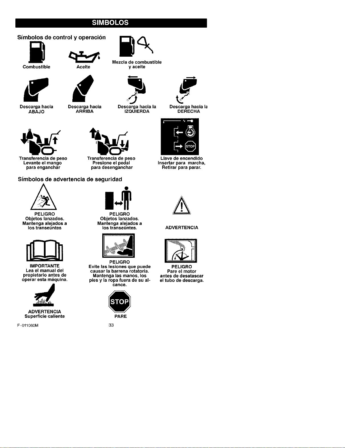
Simbolos de control y operacion
Mezcla de combustible
Combustible Aceite y aceite
Descarga hacia Descarga hacia Descarga hacia la Descarga hacia la
ABAJO ARRIBA IZQUIERDA DERECHA
i' o]
Transferencia de peso Transferencia de peso Llave de encendido
Levante el mango Presione el pedal Insertar para marcha,
para enganchar para desenganchar Retirar para parar.
Simbolos de advertencia de seguridad
N .
PELIGRO PELIGRO
Objetos lanzados.
Mantenga alejados a
los transeuntes
Objetos lanzados.
Mantenga alejados a
los transet_ntes. ADVERTENCIA
IMPORTANTE
Lea el manual del
propietario antes de
operar esta maquina.
PEUGRO
Evite las lesiones que pueds
causar la barrena rotatoria.
Mantenga las manos, los
pies y la ropa fuera de su al-
canoe=
PELIGRO
Pare el motor
antes de dssatascar
el tubo de descarga.
ADVERTENClA
Superficie caliente PARE
F-O11060M 33
I ::1_[.,',.__,'q_vjI=]IV_,IJ_l
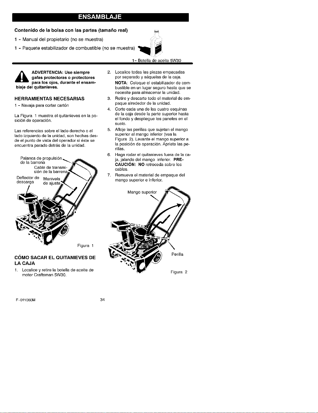
Contenido de la bolsa con las partes (tamaiio real)
1 - Manual del propietario (no se muestra)
1 - Paquete estabilizador de combustible (no se muestra)
1- Botella de aceite 5W30
,_ ADVERTENClA: Use siempre
gafas protectoras o protectores
para los ojos, durante el ensam-
blaje del quitanieves.
HERRAMIENTAS NECESARIAS
1- Navaja para co[tar cart6n
La Figura 1 muestra el quitanieves en Ia po-
siciSn de operaci6n.
Las referencias sobre el lado derecho o el
Iado izquierdo de la unidad, son hechas des-
de el punto de vista del operador si este se
encuentra parado detras de la unidad.
Palanca de propuIsi6n _,
de la barrena
Cable de transmi-
Deflector de Manivela
descarga de a
Figura 1
C6MO SACAR EL QUlTANIEVES DE
LA CAJA
1. Localice y retire la botella de aceite de
motor Craftsman 5W30.
2. Localice todas las piezas empacadas
por separado y saquelas de la caja.
NOTA: Coloque el estabilizador de com-
bustible en un lugar seguro hasta que se
necesite para almacenar Ia unidad.
3. Retire y descarte todo el material de em-
paque alrededor de la unidad.
4, Corte cada una de las cuatro esquinas
de la caja desde la parte superior hasta
el fondo y despliegue los paneles en el
suelo.
5.
Afloje las periIlas que sujetan el mango
superior al mango inferior (yea la
Figura 2). Levante el mango superior a
la posici6n de operaci6n. Apriete ias pe-
rillas.
Haga rodar et quitanieves fuera de la ca-
ja, jalando del mango inferior. PRE-
CAUClON: NO retroceda sobre los
cables.
Remueva et material de empaque del
mango superior e inferior.
Mango superior
Perilla
_*.41
Figura 2
F-011060M 34
I ::1_[.:.__,'q_vjI:] IV_,IJ_l
_" LISTA DE REVISION
Antes de operar su nuevo quitanieves, y pa-
ra asegurar que obtenga el mejor rendimien-
to y la mayor satisfacci6n de este producto
de calidad, por favor haga un repaso de la
siguiente lista de revisi6n:
_' Se han completado todas las instruccio-
nes de ensamblado.
_' El tubo de descarga gira libremente.
_' No quedan piezas sueltas en la caja de
cart6n.
AI mismo tiempo que aprende a usar su qui-
tanieves, preste mucha atenci6n a ios deta-
lies siguientes:
#" El aceite del motor est_ al nivel adecuado.
#" AsegSrese que el tanque de gasolina este
Ileno con gasolina limpia, fresca y sin plo-
mo.
#" Familiaricese con todos los controles, su
ubicaci6n y funci6n. Opere los controles
antes de hacer arranoar el motor.
F-011060M 35

CONOZCA SU QUITANIEVES
LEA ESTE MANUAL DE INSTRUCCIONES Y LAS REGLAS DE SEGURI-
DAD ANTES DE OPERAR SU QUITANIEVES. Compare las ilustraciones con su
QUITANIEVES parafamiliarizarse con la ubicaci6n de los diversos controles y ajustes. Guarde
este manual p8ra referenoiafutura.
Palanc8 de propulsi6n
de I8 barren8 --
Manij8 de
Deflector del tu- arrsnque
bo de descarga manual
Tubo de
descarga
Palanca Bot6n
Control de ignici6n cebador
deI ahogador
Figura 3
Palanca de propulsion de la barrrena - Ac-
cion8 y detiene la barren8.
Manivela de ajuste - Cambia la direcci6n de
Ia descarga de nieve.
Deflector del tubo de descarga -Cambia la
distsncia del Ianzamiento de 18nieve.
Tubo de descarga - Cambi8 18direcci6n en
que se lanza la nieve.
F-011060M 36
Palanca de ignicion- Debe moverse a la
posici6n de encendido para 8rrancar el motor,
Manija de arranque manual - Arranca el
motor manualmente.
Control del ahogador - Se usa para arran-
car un motor frio.
Botbn de cebado - Injecta el combustible
directamente en el csrburador 0 distribuidor
para un arrsnque rApido en temperaturas
frias.
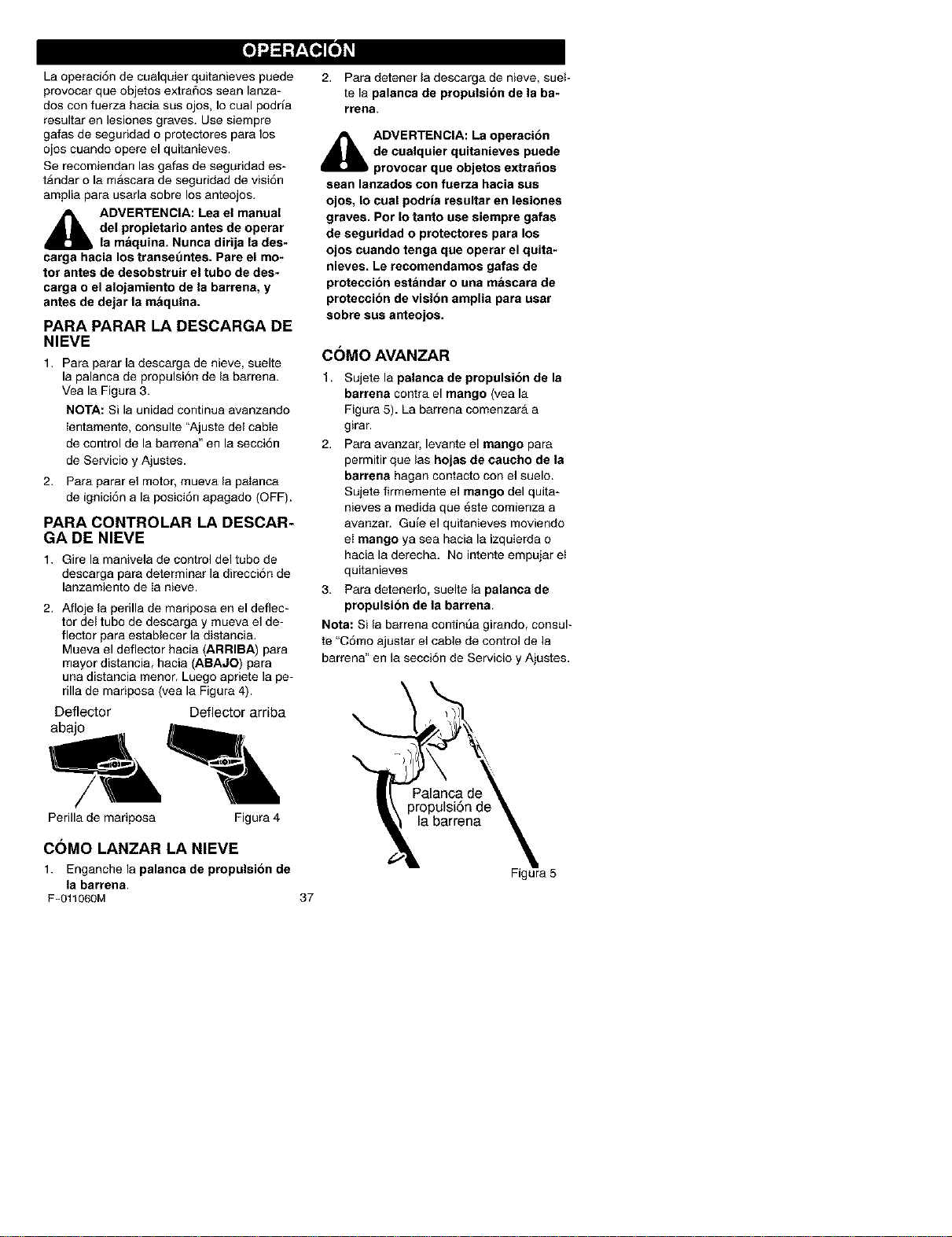
Laoperaci6ndecualquierquitanievespuede
provocarqueobjetosextraSosseaRlanza-
dosconfuerzahaciasusojos,Iocualpodria
resultarenlesionesgraves.Usesiempre
gafasdeseguridadoprotectoresparalos
ojoscuandoopereelquitanieves.
Serecomiendanlasgafasdeseguridades-
tandarolamascaradeseguridaddevisi6n
ampliaparausarlasobrelosanteojos.
_IL ADVERTENCIA: Lea el manual
del propietario antes de operar
la maquina. Nunca dirija la des-
carga hacia los transeuntes. Pare el mo-
tor antes de desobstroir el tubo de des-
carga o el alojamiento de la barrena, y
antes de dejar la maquina.
PARA PARAR LA DESCARGA DE
NIEVE
1. Para parar la descarga de nieve, suelte
la palanca de propulsi6n de la barrena.
Vea la Figura 3.
NOTA: Si la unidad continua avanzando
ientamente, consulte "Ajuste del cable
de control de la barrena" en la secci6n
de Servicio y Ajustes.
2. Para parar el motor, mueva la palanca
de ignici6n a la posici6n apagado (OFF).
PARA CONTROLAR LA DESCAR-
GA DE NIEVE
1. Gire la manivela de control del tubo de
descarga para determinar la direcci6n de
lanzamiento de Ia nieve.
2. Afloje la perilla de mariposa en el deflec-
tor del tube de descarga y mueva el de-
flector para establecer la distancia.
Mueva el deflector hacia (ARRIBA) para
mayor distancia, hacia (ABAJO) para
una distancia menor. Luego apriete la pe-
rilla de mariposa (yea la Figura 4).
Deflector Deflector arriba
abajo
Perilla de mariposa Figura 4
COMO LANZAR LA NIEVE
1. Enganohe la palanca de propulsion de
la barrena.
F-O11060M
2. Para detener la descarga de nieve, suet-
te la palanca de propulsion de la ba-
rrena.
_1= ADVERTENCIA: La operaoibn
de oualquier quitanieves puede
provocar que objetos extraSos
seaR lanzados con faerza hacia sus
ojos, Io cual podria resoltar en lesiones
graves. Por Io tanto use siempre galas
de seguridad o protectores para los
ojos cuando tenga que operar el quita-
nieves. Le recomendamos gafas de
proteccion estAndar o ana mascara de
proteccion de vision amplia para usar
sobre sus anteojos.
C()MO AVANZAR
t. Sujete la palanca de propulsibn de la
barrena contra el mango (yea la
Figura 5). La barrena comenzarA a
girar.
2. Para avanzar, levante el mango para
permitir que las hojas de caucho de la
barrena hagan contacto con el suelo.
Sujete firmemente el mango del quita-
nieves a medida que 6ste comienza a
avanzar. Guie el quitanieves moviendo
el mango ya sea hacia la izquierda o
hacia la derecha. No intente empujar et
quitanieves
3. Para detenerlo, suelte la palanca de
propulsion de la barrens.
Nots: Si la barrena continSa girando, consul-
te "C6mo ajustar el cable de control de la
barrena" en la secci6n de Servicio y Ajustes.
37
Figura 5
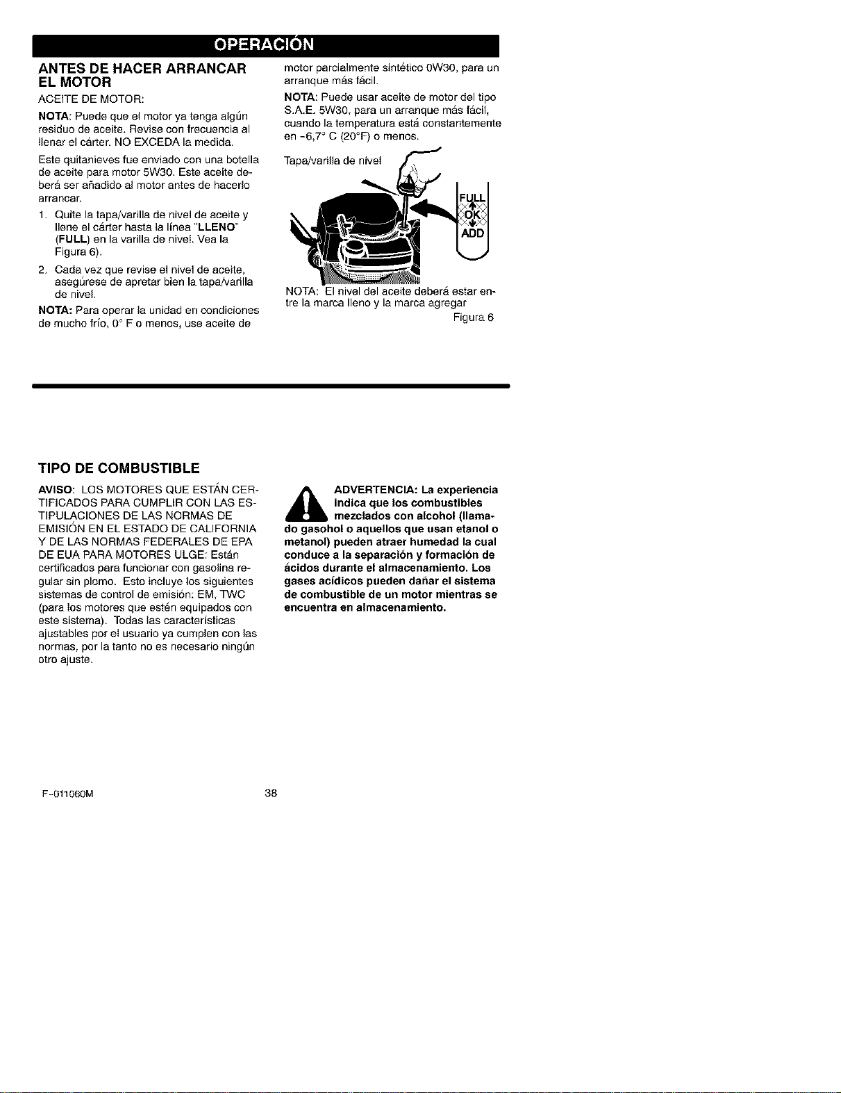
ANTES DE HACER ARRANCAR
EL MOTOR
ACEITE DE MOTOR:
NOTA: Puede que el motor ya tenga algSn
residuo de aceite. Revise con frecuencia al
ilenar el carter. NO EXCEDA la medida.
Este quitanieves fue enviado con una botella
de aceite para motor 5W30. Este aceite de-
hera set aSadido al motor antes de hacerlo
arranoar.
1. Quite la tapa/varilla de nivel de aceite y
Ilene el carter hasta la linea "LLENO"
(FULL) en la varilla de niveL Vea la
Figura 6).
2. Cada vez que revise el nivel de aceite,
asegSrese de apretar bien la tapa/varilla
de nivei.
NOTA: Para operar la unidad en condiciones
de mucho frio, 0° F o menos, use aceite de
motor parcialmente sintetico 0W30, para un
arranque mas facil.
NOTA: Puede usar aceite de motor del tipo
S.A.E. 5W30, para un arranque mas facil,
ouando la temperatura est_ constantemerlte
en -6,7 _'C (20°F) o menos.
Tapa/varilla de nivet
NOTA: El nivel del aceite deberA estar en-
tre la marca Ileno y la marca agregar
Figura 6
TIPO DE COMBUSTIBLE
AVISO: LOS MOTORES QUE EST_.N CER-
TIFiCADOS PARA CUMPLiR CON LAS ES-
TIPULAClONES DE LAS NORMAS DE
EMiSiON EN EL ESTADO DE CALIFORNIA
Y DE LAS NORMAS FEDERALES DE EPA
DE EUA PARA MOTORES ULGE: Est_n
certiflcados para funcionar con gasolina re-
gular sin plomo. Esto incluye los siguientes
sistemas de control de emisi6n: EM, TWC
(para Ios motores que est6n equipados con
este sistema). Todas las caracteristicas
ajustables por el usuario ya cumplen con las
normas, pot la tanto no es necesario ningLin
otro ajuste.
_lb DVERTENClA: La experiencia
indica que los combustibles
mezclados con alcohol (llama-
do gasohol o aquellos que osan etanol o
metanol) pueden atraer humedad la cual
conduce a la separacion y formacion de
acidos durante el almacenamiento. Los
gases acidicos pueden da_ar el sistema
de combustible de on motor mientras se
encuentra en almacenamiento.
F-011060M 38
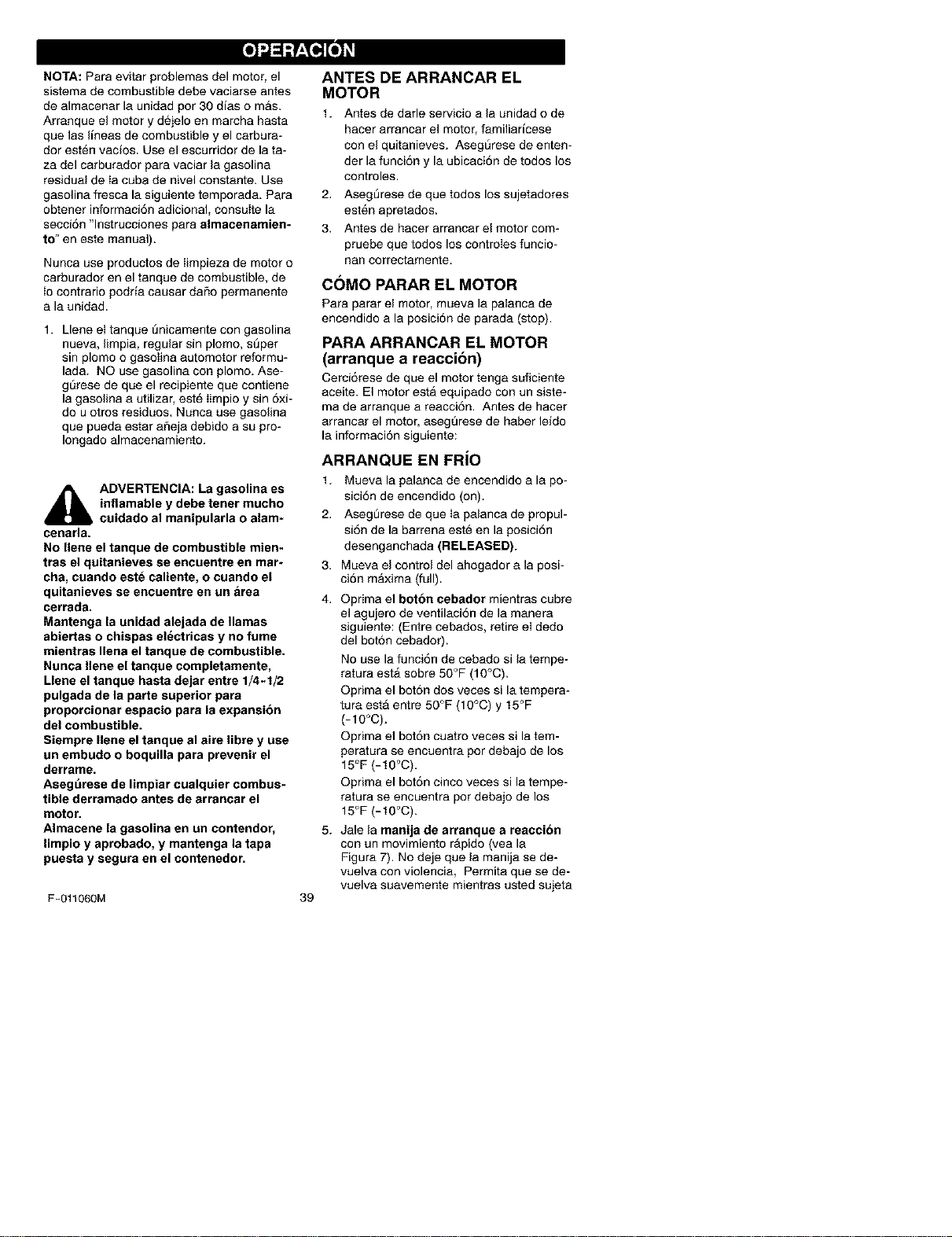
NOTA: Para evitar problemas del motor, el
sistema de combustible debe vaciarse antes
de almacenar la unidad por 30 dias o mas.
Arranque el motor y dejelo en marcha hasta
que las lineas de combustible y el carbura-
dor esten vacios. Use el escurridor de la ta-
za del carburador para vaciar la gasolina
residual de Ia cuba de nivel constante. Use
gasolina fresca la siguiente temporada. Para
obtener informaci6n adicional, consulte la
secci6n "lnstrucciones para almacenamien-
to" en este manual).
Nunca use productos de Iimpieza de motor o
carburador en el tanque de combustible, de
io contrario podria causar daflo permanente
a la unidad.
1. Llene el tanque Enicamente con gasolina
nueva, limpia, regular sin plomo, s@er
sin plomo o gasoIina automotor reformu-
lada. NO use gasolina con plomo. Ase-
gt_rese de que el recipiente que contiene
la gasolina a utilizar, este Iimpio y sin 6xi-
do u otros residuos. Nunca use gasolina
que pueda estar afieja debido a su pro-
Iongado almacenamiento.
_lb DVERTENCIA: La gasolina es
inflamable y debe tener mucho
cuidado al manipularla o alam*
cenarla.
No Ilene el tanque de combustible mien-
tras el quitanieves se encuentre en mar-
cha, cuando este caliente, o cuando el
quitanieves se encuentre en un area
cerrada.
Mantenga la unidad alejada de llamas
abiertas o chispas electricas y no fume
mientras Ilena el tanque de combustible.
Nunca Ilene el tanque completamente,
Llene el tanque hasta dejar entre 1/4-1/2
pulgada de la parte superior para
proporcionar espacio para la expansion
del combustible.
Siempre Ilene el tanque al aire libre y use
un embudo o boquilla para prevenir el
derrame.
Asegt_rese de limpiar cualquier combus-
tible derramado antes de arrancar el
motor.
Almacene la gasolina en un contendor,
limpio y aprobado, y mantenga la tapa
puesta y segura en el contenedor.
F-011060M
39
ANTES DEARRANCAREL
MOTOR
1. Antes de darle servicio a la unidad o de
hacer arrancar el motor, familiaricese
con el quitanieves. Aseg5rese de enten-
der la funci6n y la ubicaci6n de todos los
controles.
2. AsegSrese de que todos los sujetadores
esten apretados.
3. Antes de haoer arrancar el motor com-
pruebe que todos los controIes funcio-
nan correctamente.
COMOPARARELMOTOR
Para parar el motor, mueva la palanca de
encendido a la posici6n de parada (stop).
PARA ARRANCAR EL MOTOR
(arranque a reaccibn)
Cerci6rese de que el motor tenga suficiente
aceite. El motor esta equipado con un siste-
ma de arranque a reacci6n. Antes de hacer
arrancar el motor, asegt3rese de haber leido
la informaci6n siguiente:
ARRANQUE EN FRJO
1. Mueva la palanca de encendido a la po-
sici6n de encendido (on).
2. AsegSrese de que Ia palanca de propul-
si6n de la barrena est@en la posici6n
desenganohada (RELEASED).
3. Mueva el control del ahogador a la posi-
oi6n m_xima (full).
4. Oprima el boron cebador mientras cubre
el agujero de ventilaci6n de la manera
siguiente: (Entre cebados, retire el dedo
del bot6n cebador).
No use la funci6n de cebado si la tempe-
ratura est_ sobre 50°F (10°C).
Oprima el bot6n dos veces si la tempera-
tufa estA entre 50°F (10°C) y t5°F
(-10°C).
Oprima el bot6n cuatro veces si la tem-
peratura se encuentra por debajo de los
15°F (-t0°C).
Oprima el bot6n cinco veces si la tempe-
ratura se encuentra pot debajo de los
15°F (-t 0°C).
5. Jale la manija de arranque a reaccibn
con un rnovimiente rApido(yea la
Figura 7). No deje que la manija se de-
vuelva con violencia, Permita que se de-
vuelva suavemente mientras usted sujeta
firmementela manija de arranque a
reaccibn.
Jale rApidamente Ia manija
Figura 7
6, Mientras el motor se v8 calentando, mue-
va 18palanc8 det ahogador a 18posici6n
de "1/2", Cuando el motor este funcio-
nando uniformemente, muev8 la palanca
del ahogador a la posici6n "No choke",
NOTA: Deje que el motor se c81iente pot
algunos minutos antes de comenzar a remo-
ver y arrojar nieve, en tempersturas inferio-
res a los O°F (-18_'C),
ARRANQUE EN CALIENTE
Si est_ arrancando un motor caliente des-
pu6s de haberlo apagado por un periodo
corto, deje el ahogador en "APAGADO"
(OFF) y no optima el bot6n cebador.
ARRANQUE CONGELADO
Si el dispositivo de arranque esta congetado
y no puede hacer 8rrsncar el motor:
1. Jale la mayor Iongitud de cuerda del
arrancador 8 reacci6n como sea posible.
2. Suelte la manija del arrancador y dejeta
que se enrolle rapidamente contr8 el
arrancador.
Si el motor todav[8 no arranca, repita estos
pasos hasta que Iogre encenderlo, Luego
continue con Ias instrucciones para arranque
en frio.
Para 8yudar 8 evitar que se congele el
8rrancador a reacci6n y los controles del
motor, proceda de 18manera siguiente des-
pues de cad8 trabsjo de remoci6n de nieve,
t, Con el motor en march8, jale la cuerda
de 8rranque energica y continuadamente
extendiendo todo el brazo, unas tres 0
cuatro veces. El jalado de la cuerda de
arranque producira un sonido de repi-
queteo fuerte, Esto no causa daflo ni 81
motor ni al 8rrsnoador,
Con el motor parado, limpie tod8 la nieve
y humedad de 18cubiert8 det carburador
en el area de las palancas de control.
Asimismo, muev8 el control de 8celera-
ci6n, control del 8hogador y manija del
arrancador varias veoes,
_1= DVERTENCIA: Nunca arran-
que el motor dentro de un re-
cinto cerrado o en areas con
poca ventilacibn. Los gases de escape
del motor oontienen MONOXIDO DE
CARBONO, UN GAS INODORO Y MOR-
TAL. Mantenga las manos, los pies, el
pelo y la ropas sueltas alejadas de las
partes en movimiento tanto del motor
como del quitanieves. Latemperatura
del silenciador y de las piezas alrededor
del silenciador puede exceder los 150°1£
Evite tocar estas partes. Mantenga ale-
gados los niSos y jbvenes del quitanie-
ves cuando _ste esta en funcionamiento;
NO les deja operar la unidad.
,_ ADVERTENCIA: No intente re-
mover ning_3n objeto atascado
en la barrena sin tomar primero
las precauciones siguientes:
Suelte la palanca de propulsion de la
barrena.
Maeva la palanca de encendido a la
posicion stop para parar el motor.
Desconecte el cable de la bujia.
No coloque las manos en la barrena o
en el tubo de descarga. Use una barra
de apalancamiento.
SUGERENCIAS PARA EL
LANZAMIENTO DE NIEVE
1. Cuando se levsnt8 el mango, las hojas
de cauoho de la barren8 entran en con-
tacto con el suelo y el quitanieves avan-
F-O11060M
4O
z8, Cuando se suelta la palanca de
propulsiSn de la barrena, las hojas de
caucho de la barren8 se paran. Si las
hojas de caucho no paran, consulte "C6-
mo ajustar el cable de propulsi6n de la
barrena"enIasecci6ndeServicioy
Ajustes.
2. EllanzamientodenievemAsefectivose
Iogracuandolanievesequitainmedia-
tamentedespu6sdelanevada.
3. Paraquitarcompletamentelanieve,so-
brepongaligeramenteIaspasadasdel
quitanieves.
4. Cuandoseaposible,descarguelanieve
afavordelviento.
5. Sepuedeajustarladistanciaalaquela
nieveseralanzada,moviendoeldeflec-
tordeltubodedescarga.Paramasdis-
tancialevanteeldeflector,paramenos
distanciabajeeldeflector.
6. Encondicionesdemuchoviento,bajeel
deflectordeltubodedescargaparadiri-
girlanievelanzadamascercadeIsuelo
paraevitarqueelvientolasoplehacia
Areasnodeseadas.
7. Parasuseguridadyparaprevenirelda-
5oaIquitanieves,mantengaetAreaque
vaalimpiar,librederocas,juguetesy
otrosobjetosextraSos.
8. Nouselafunci6ndepropulsi6ndela
barrenacuandoestepasandosobreen-
tradasdeautocubiertascongravaoto-
catriturada.Muevaelmangohacia
abajoparaIevantarIigeramenteIabarre-
na.
9. Lavelocidaddeavaricedelquitanieves
dependedelaprofundidadydelpesode
Ianieve.LamaneramAseficientede
usarelquitanievesseradeterminadapot
suexperienciabajodiversascondicio-
nes,
10.Despuesdecadatrabajodejequeel
motorfuncioneporunosminutos.As{
sederretiralanieveyeihieloacumula-
dosenetmotor.
11. Limpie el quitanieves despu6s de cada
USO,
12. Quite el hielo, la nieve y los residuos de
todo el quitanieves, EnjuAguelo con
agua para quitarle toda la sal y otros
productos quimicos. Seque el quitanie-
yes.
NIEVE SECA Y DE
POCA PROFUNDIDAD
1. La nieve que se acumule hasta profundi-
dades de ocho puIgadas puede quitarse
rapida y facilmente, caminando a una
velocidad moderada con el quitanieves.
Para acumulaciones de nieve de mayor
profundidad, camine mas lento para per-
mitir la descarga uniforme de nieve tan
pronto sea recogida pot la barrena.
2. Intente descargar la nieve a favor del
viento,
NIEVE MOJADA Y COMPACTA
Avance lentamente para despejar la nieve
mojada y compact& Si este tipo de nieve
hace que la barrena gire mas lento o empie-
za a atascar et tubo de descarga, retirese un
poco y empiece una serie de movimientos
cortos con el quitanieves, hacia adelante y
hacia arras. Estos movimientos cortos en la
nieve (de cuatro a seis pulgadas), ayudaran
a arrojar la nieve deI tubo de descarga.
BANCOS Y ACUMULACIONES
GRANDES DE NIEVE
Para despejar la nieve que se acumula a
una altura mayor que el quitanieves, use et
m@todo descrito anteriormente (movimientos
cortos hacia adelante y hacia atrAs). Oriente
el tubo de descarga en direcci6n opuesta a
la del banco o acumulaci6n grande de nieve.
La remoci6n de este tipo de nieve tomarA
mas tiempo.
F-O11060M 41
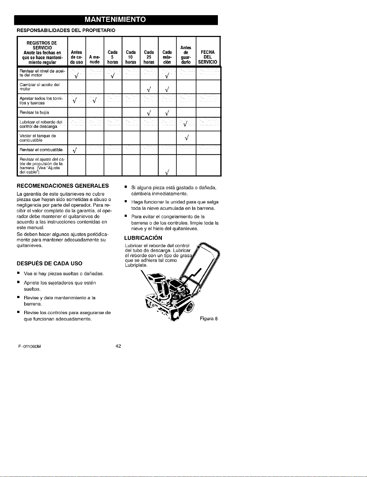
RESPONSABILIDADES DEL PROPIETARIO
REGISTROSDE
SERVICIO Antes
Anotelas fechasen Antes Cada Cada Cada Cada de FECHA
que se hacemanteni- deca- A me- 5 10 25 esta- gear- DEL
mientoregular da uso nudo horas horas horas ei6n darlo SERVICIO
Reviserel nivet deacei- ' ' ' ' ' ' ' '
te del motor _/ Vf _/ "
Cambiar eI aceitedei
motor _/ _/
Apretar todos_ostorni-' ,/ ' _/ ' I I I I I
Ilosytuercas _
Reviser la bujia _/ _/
, , , , , , ,
Lubricar e_reborde del
control de descarga ......
Vaciarettanque de _/
combustibJe
Reviserel combustible _/ .......
Reviser el ajuste del ca-
Ne de propulsi6n de la
barrena (Vea"Ajuste
de1cable") _/
RECOMENDACIONESGENERALES
La garanSa de este quitanieves no cubre
piezas que hayan sido sometidas a abuso o
negligencia pot parte del operador. Pare re-
cibir el valor completo de la garantia, el ope-
rador debe mantener el quitanieves de
acuerdo a las instruooiones contenidas en
este manual,
Se deben hacer algunos ajustes peri6dica-
mente para msntener adecuadamente su
quitanieves.
DESPUES DE CADA USO
• Yea si hay piezas sueltas o da_adas.
• Apriete los sujetadores que esten
sueltos.
• Revise y dele mantenimiento ala
barrena.
• Revise los controles para asegurarse de
que funcionan adecuadamente.
• Si alguna pieza estA gastada o daSada,
cambiela inmediatamente.
• Haga funcionar la unidad para que salga
toda la nieve acumulada en la barren&
•Para evitar el congelamiento de la
barrena o de los controles, limpie toda la
nieve y ei hielo del quitanieves.
LUBRICACION
Lubricar el reborde del control
del tubo de descarga. Lubricar
el reborde con un
que se adhiera tal como
Lubriptate.
\
%
Figure 8
F-011060M 42
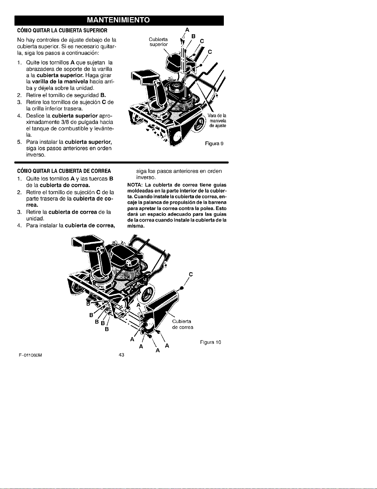
C6MO QUITARLACUBIERTASUPERIOR
No hay controles de ajuste debajo de la
cubierta superior. Si es necesario quitar-
la, siga los pasos a continuaci6n:
1. Quite los tornillos A que sujetan la
abrazadera de soporte de la varilla
a la eubierte superior. Haga girar
la varilla de la manivela hacia arri-
bay dejela sobre la unidad.
2. Retire el tornillo de seguridad B.
3. Retire los tornillos de sujeci6n C de
la orilla inferior trasera.
4. Deslice la cubierta superior apro-
ximadamente 3/8 de pulgada hacia
el tanque de combustible y lev&nte-
la.
5. Para instalar la cubierte superior,
siga los pasos anteriores en orden
inverse.
Cubierta
superior
A
B
C
C
Varadela
manivela
deajuste
Figura 9
C6MO QUITARLACUBIERTADECORREA
1. Quite los tornillos A y las tuercas B
de la eubierta de eorrea.
2. Retire el tornillo de sujeci6n C de la
parte trasera de la cubierta de co-
rrea,
3. Retire la cubierta de correa de la
unidad.
4. Para instalar la cubierta de correa,
siga los pasos anteriores en orden
inverse.
NOTA: La cubierta de correa tiene guias
moldeadas en la parte interior de la cobier-
ta. Cuando instale la cubierta de correa, en-
caje la palanca de propulsion de la barrena
para apretar la correa contra la polea. Esto
dara un espacio adecuado para las guias
de la correa coando instale lacubierta de la
misma.
C
/
BI
B
Cubierta
de oorrea
A
Figura 10
A
A
A
F-011060M 43
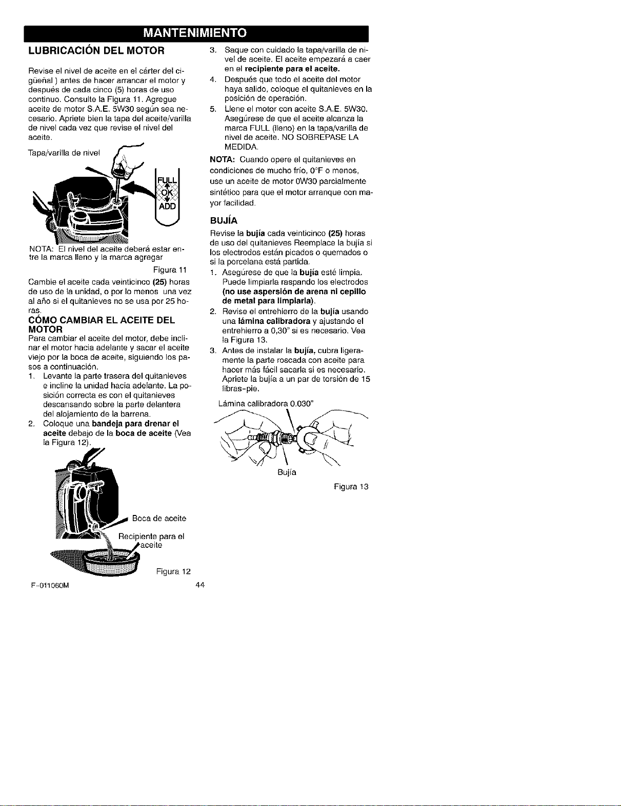
LUBRICACION DEL MOTOR
Revise el nivel de aceite en el carter deI ci-
gt3efial ) antes de hacer arrancar el motor y
despues de cada cinco (5) horas de use
continue. Consulte la Figura 11. Agregue
aceite de motor S.A.E. 5W30 segSn sea ne-
cesario. Apriete bien la tapa del aceite/varilla
de nivel cada vez que revise et nivet del
aceite.
Tapa/varilla de nivel
NOTA: El nivel del aceite debera estar en-
tre la marca Ileno y la marca agregar
Figura 11
Cambie el aceite cada veinticinco (25) horas
de use de la unidad, o per Io menos una vez
al afio si el quitanieves no se usa per 25 ho-
ras,
C6MO CAMBIAR EL ACEITE DEL
MOTOR
Para cambiar el aceite del motor, debe incli-
nat el motor hacia adelante y sacar el aceite
viejo per la boca de aceite, siguiendo los pa-
sos a continuaci6n.
1. Levante la parte trasera del quitanieves
e incline la unidad hacia adelante. La po-
sici6n correcta es con el quitanieves
descansando sobre la parte delantera
del alojamiento de la barrena.
2. Coloque una bandeja pare drenar el
aceite debajo de la boca de aceite (Vea
Ia Figura 12).
3. Saque con cuidado la tapa/varilla de ni-
vel de aceite. El aceite empezarA a caer
en el reeipiente pare el aceite.
4. Despu6s que todo el aceite del motor
haya salido, coloque el quitanieves en la
posici6n de operaci6n.
5, Uene el motor con aceite S,A,E, 5W30,
AsegSrese de que el aceite alcanza la
marca FULL (]leno) en la tapa/varilla de
nivel de aceite, NO SOBREPASE LA
MEDIDA.
NOTA: Cuando opere el quitanieves en
condiciones de mucho frio, 0"F o menos,
use un aceite de motor 0W30 parcialmente
sintetico para que el motor arranque con ma-
yor facilidad.
BUJiA
Revise Ia bujia cada veinticinco (25) horas
de use del quitanieves Reemplace la bujla si
los electrodes est_n picados o quemados o
si la porcelana estA partida.
t. Asegt_rese de que la bujia este limpia.
Puede limpiarla raspando los electrodes
(no use aspersion de arena ni cepillo
de metal para limpiarla),
2. Revise el entrehierro de la bujia usando
una lamina calibradora y ajustando el
entrehierro a 0,30" si es necesario. Vea
Ia Figura 13,
3. Antes de instalar la bujia, cubra ligera-
mente la parte roscada con aceite para
hacer mas facil sacarla si es necesario.
Apriete la bujia a un par de torsi6n de 15
libras- pie.
LAmina calibradora 0.030"
Bujia
Figura 13
Recipiente para el
Figura 12
F-011060M 44
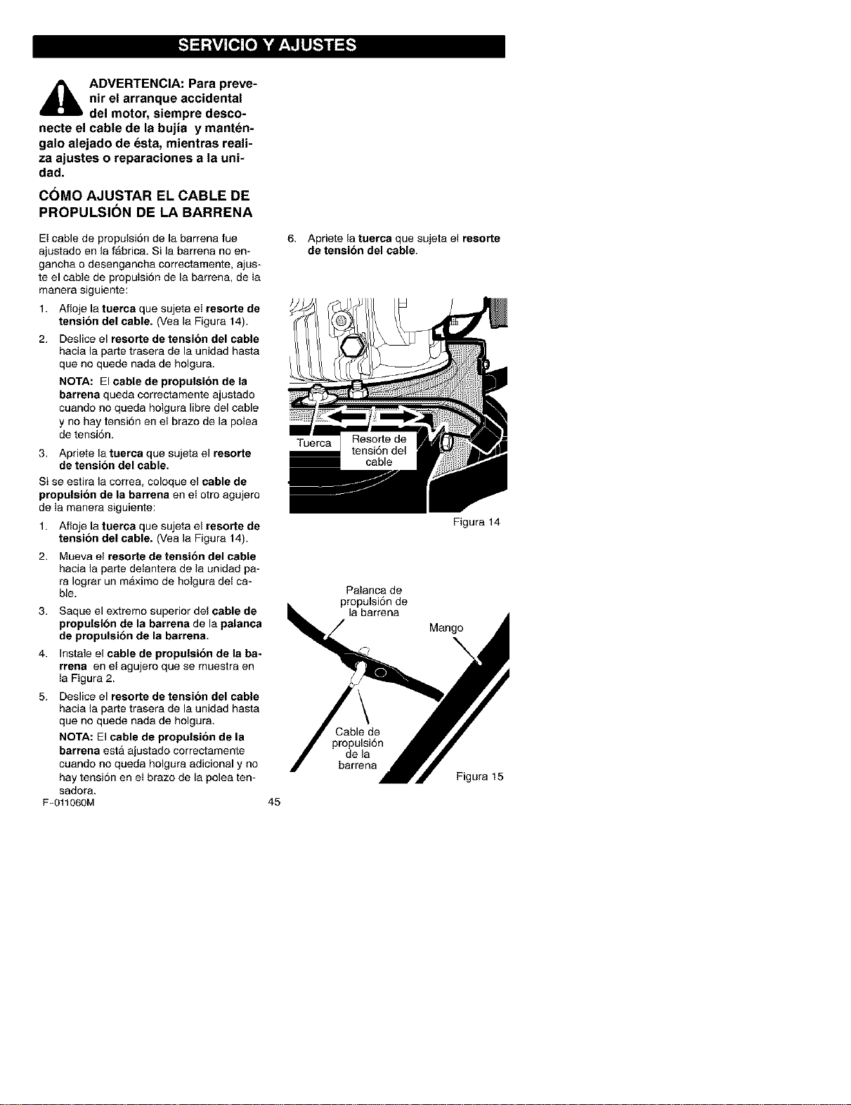
,_ ADVERTENCIA: Para preve-
nir el arranque accidental
del motor, siempre desco-
necte el cable de la bujia y manten-
galo alejado de esta, mientras reali-
za ajustes o reparaciones a la uni-
dad.
COMO AJUSTAR EL CABLE DE
PROPULSION DE LA BARRENA
El cable de propulsi6n de la barrena fue
ajustado en la fabric& Si la barrena no en-
ganoba o desengancba correctamente, ajus-
te el cable de propulsi6n de la barrena, de Ia
manera siguiente:
1. Afloje la tuerca que sujeta eI resorte de
tension del cable. (Vea la Figura 14).
2. Deslice el resorte de tension del cable
hacia la parte trasera de la unidad hasta
que no quede nada de holgura.
NOTA: El cable de propulsion de la
barrena queda correctamente ajustado
cuando no queda holgura libre del cable
y no hay tensi6n en et brazo de la polea
de tensi6n.
3. Apriete la taerca que sujeta el reaorte
de tension del cable.
Si se estira la correa, coloque el cable de
propulsion de la barrena en el otro agujero
de Ia manera siguiente:
1. Afloje la tuerca que sujeta el resorte de
tension del cable. (Vea la Figura 14).
2. Mueva el resorte de tensibn del cable
hacia la parte detantera de la unidad pa-
ra Iograr un maximo de holgura det ca-
ble.
3. Saque el extremo superior del cable de
propulsibn de la barrena de la palanca
de propulsibn de la barrena.
4. Instale el cable de propulsibn de la ba-
rrena en el agujero que se muestra en
Ia Figura 2.
5. Deslice el resorte de tension del cable
hacia la parte trasera de la unidad hasta
que no quede nada de holgura.
NOTA: El cable de propulsion de la
barrena esta ajustado correctamente
cuando no queda bolgura adicional y no
hay tensi6n en ei brazo de la polea ten-
sadora.
F-011060M
6. Apriete la tuerca que sujeta el reaorte
de tensibn del cable.
Tuerca
m
cable
Figura 14
Palanca de
propulsi6n de
la barrena
Mango
\
45
Cable de
propulsi6n
de la
barrena
Figura 15
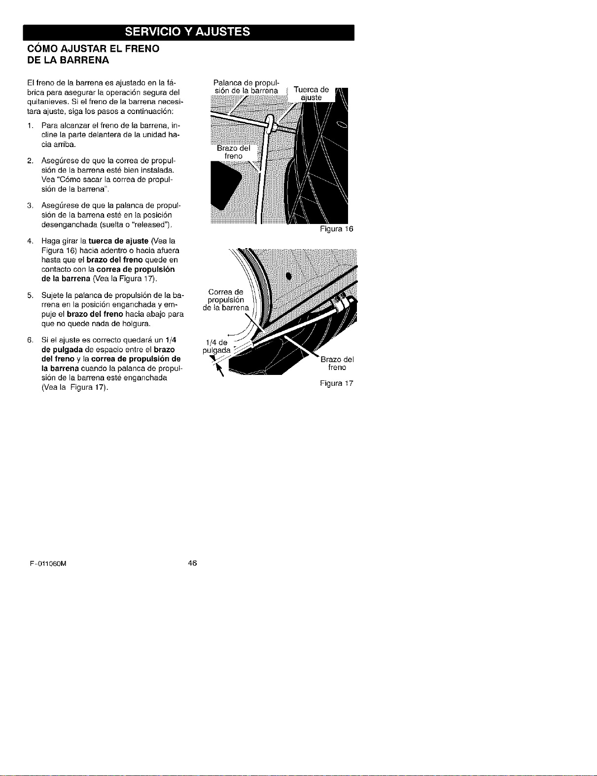
COMO AJUSTAR EL FRENO
DE LA BARRENA
El freno de la barrena es ajustado en la fa-
brica para asegurar la operaci6n segura del
quitanieves. Si el freno de la barrena necesi-
tara ajuste, siga los pasos a continuaci6n:
1. Para alcanzar el freno de la barrena, in-
cline la parte delantera de la unidad ha-
cia arriba.
2. Asegt_rese de que la correa de propul-
si6n de la barrena este bien instalada.
Vea "C6mo sacar la correa de propul-
si6n de la barrena".
3. Asegt_rese de que la palanca de propul-
si6n de la barrena este en Ia posici6n
desenganchada (suetta o "released").
4. Haga girar la tuerca de ajuste (Vea la
Figura 16) hacia adentro o hacia afuera
hasta que el brazo del freno quede en
contacto con la correa de propulsion
de la barrena (Vea Ia Figura 17).
Palanca de propul-
si6n de la barrena
Brazo del
freno
5. Sujete la palanca de propulsi6n de la ba- Correa de
propulsi6n
rrena en la posici6n enganchada y em- de Ia barrena
puje el brazo del freno hacia abajo para
que no quede nada de holgura.
6. Si el ajuste es correcto quedarA un 1/4
de pulgada de espacio entre el brazo
del freno y la correa de propulsion de
la barrena cuando la palanca de propuI-
si6n de la barrena este enganchada
(Vea la Figura 17).
1/4 de -
pulgada
Tuerca de
ajuste
Figura 16
• Braze del
freno
Figura 17
F-011060M 46
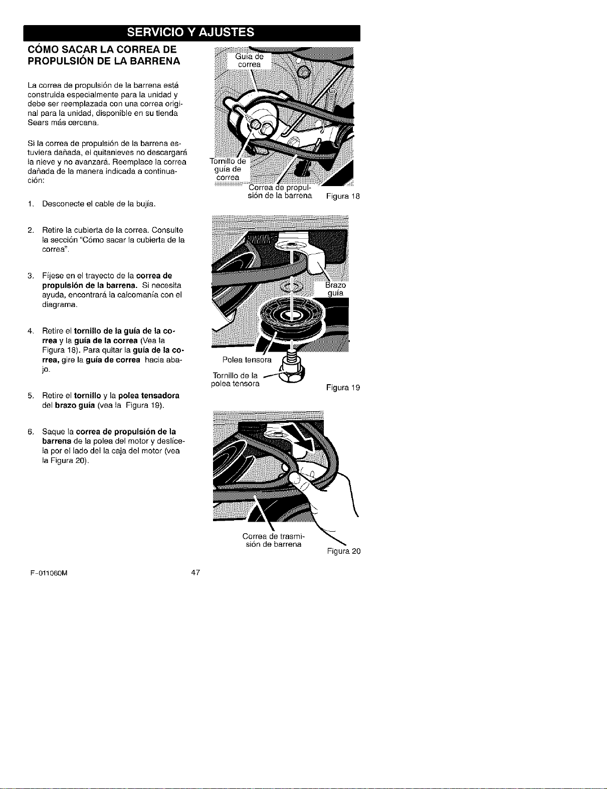
COMO SACAR LA CORREA DE
PROPULSION DE LA BARRENA
La correa de propulsi6n de la barrena esta
construida especialmente para la unidad y
debe set reemplazada con una correa origi-
nal para la unidad, disponible en su tienda
Sears mAs cercana.
Si la correa de propulsi6n de la barrena es-
tuviera daSada, el quitanieves no descargarA
ia nieve y no avanzar& Reemplace la correa
dar_ada de la manera indicada a continua-
ci6n:
1. Desconecte el cable de Ia bujia.
TornilIo de
guia de
correa
Correa de propul-
si6n de la barrena
Figura 18
2. Retire la cubierta de la correa. Consulte
Ia secci6n "C6mo sacar la cubierta de la
correa".
3. Fijese en el trayecto de la correa de
propulsibn de la barrena. Si necesita
ayuda, encontrar_ Ia calcomania con el
diagrama.
Brazo
guia
4. Retire el tornillo de la guia de la co-
rrea y la guia de la correa (Vea Ia
Figura 18). Para quitar la guia de la co-
rrea, gire la guia de correa hacia aba-
jo.
5. Retire el tornillo y la polea tensadora
del brazo guia (yea Ia Figura 19).
Potea tensora
Tornillo de la
polea tensora
Figura 19
6. Saque la correa de propulsion de la
barrena de la polea del motor y deslice-
Ia pot el lado deIla caja del motor (vea
Ia Figura 20).
Correa de trasmi-
si6n de barrena
Figura 20
F-011060M 47
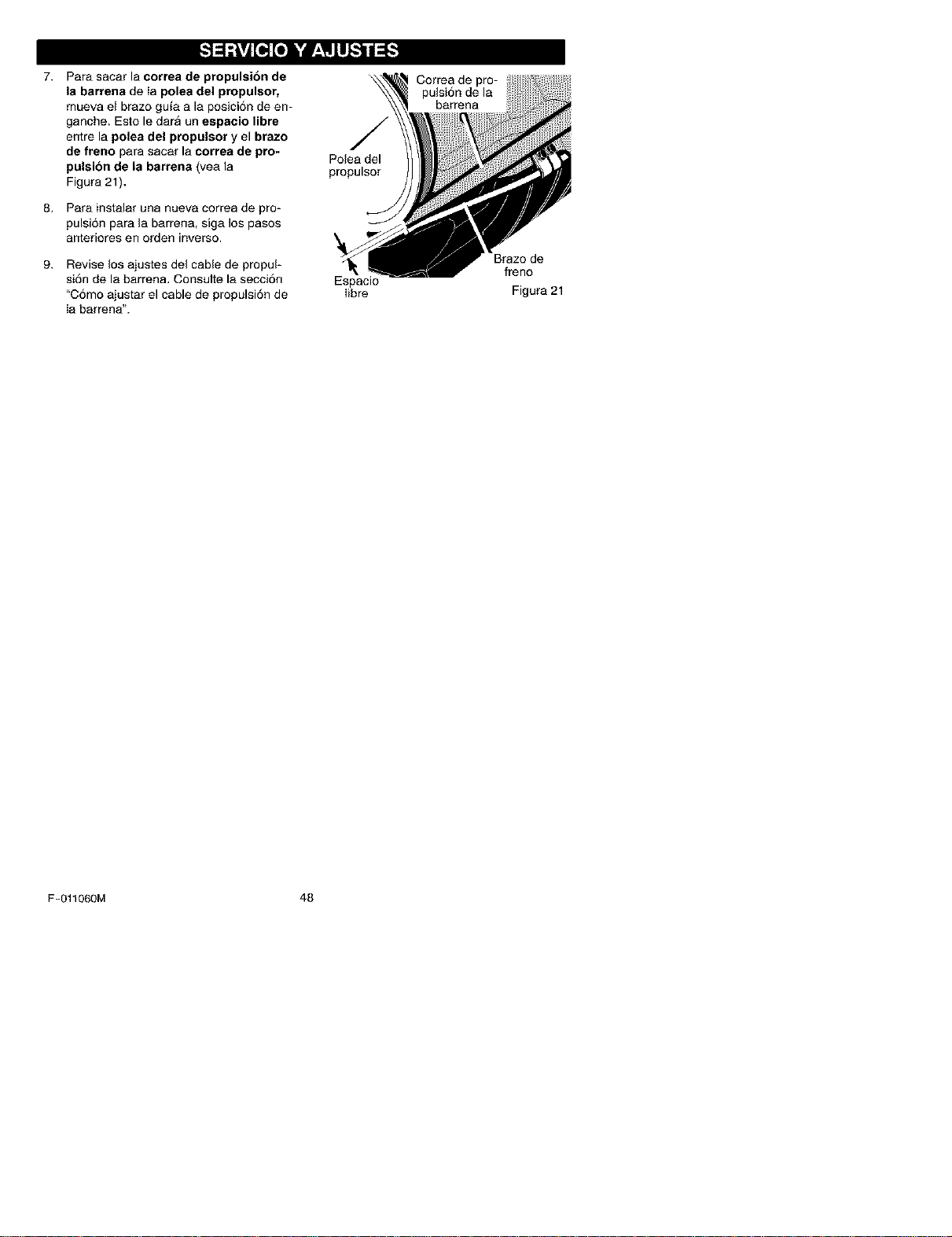
7. Para sacar la correa de propulsibn de
la barrena de Ia polea del propulsor,
mueva el brazo guia a la posici6n de en-
ganche. Esto le dara un espacio libre
entre la polea del propulsor y el brazo
de freno para sacar la correa de pro-
pulsion de la barrena (vea la
Figura 21).
8. Para instalar una nueva correa de pro-
pulsi6n para la barrena, siga los pasos
anteriores en orden inverso.
9. Revise los ajustes del cable de propul-
si6n de la barrena, Consulte la secci6n
"C6mo ajustar el cable de propulsi6n de
Ia bar rena".
Polea del
propulsor
Espacio
Iibre
Correa de pro-
pulsi6n de la
barrena
Brazo de
freno
Figura 21
F-O11060M 48
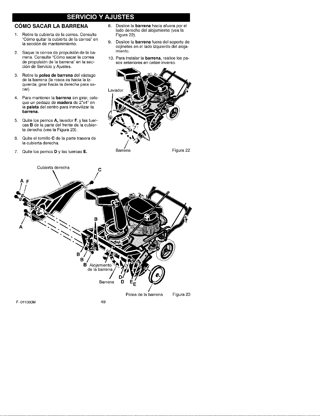
C()MO SACAR LA BARRENA 8. Deslice la barrena hacia afuera por el
lado derecho del alojamiento (yea Ia
Figura 22).
1. Retire la cubierta de la correa. Consulte
"C6mo quitar la cubierta de la correa" en
Ia secci6n de mantenimiento.
2. Saque la correa de propulsi6n de la ba-
rrena. Consulte "C6mo sacar la oorrea
de propulsi6n de la barrena" en la sec-
ei6n de Servicio y Ajustes.
3. Retire la polea de barrena del vastago
de la barrena (la rosca ee hacia la iz-
quierda; girar hacia Ia derecha para sa-
car).
4. Para mantener la barrena sin girar, colo-
que un pedazo de madera de 2"x4" en
Ia paleta del centro para inmovilizar Ia
barrena.
5. Quite los pernos A, Iavador F, y las tuer-
cas B de la parte del frente de la cubier-
ta derecha (vea la Figura 23).
6. Quite el tornillo C de la parte trasera de
Ia cubierta derecha.
7. Quite Ios pernos D y las tuercas E.
9. Deslice la barrena fuera del soporte de
cojinetes en el lado izquierdo deI aloja-
miento.
10. Para instalar la barrena, realice los pa-
sos anteriores en orden inverso.
Lavador
Barrena Figura 22
Cubierta derecha C
AF /
B
B
B Alojamiento"
de la barrena
Barrena D
Polea de la barrena Figura 23
F-011060M 49
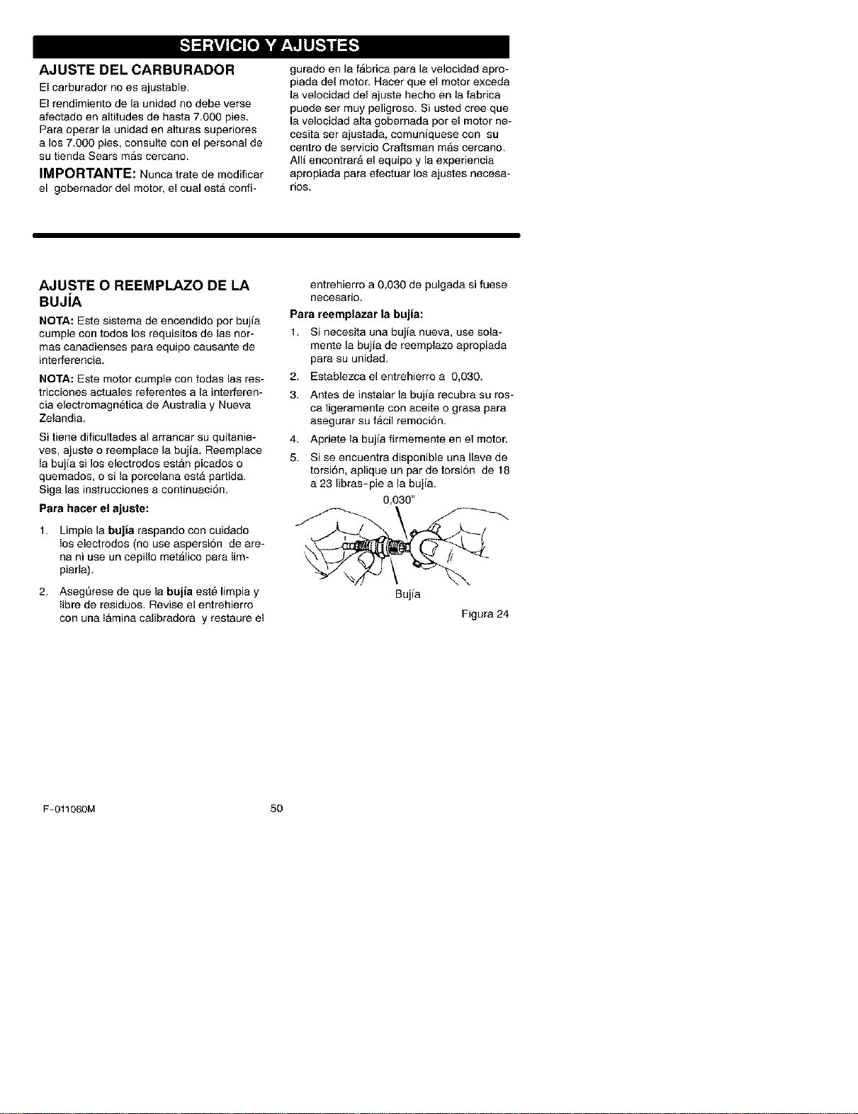
AJUSTE DEL CARBURADOR
Ei carburador no es ajustable.
El rendimiento de la unidad no debe verse
afectado en altitudes de hasta 7.000 pies.
Para operar la unidad en alturas superiores
a los 7.000 pies, consulte con el personal de
su tienda Sears mas cercano.
IMPORTANTE: Nunca trate de modificar
el gobernador det motor, el cual esta confi-
gurado en la fAbrica para la velocidad apro-
piada del motor. Hacer que el motor exceda
la velooidad del ajuste hecho en la fabrica
puede ser muy peligroso. Si usted cree que
la velocidad alta gobernada pot et motor ne-
cesita set ajustada, oomuniquese con su
centro de servicio Craftsman mas cercano.
Alli encontrarA el equipo y la experiencia
apropiada para efeotuar los ajustes necesa-
rios.
AJUSTE O REEMPLAZO DE LA
BUJiA
NOTA: Este sistema de encendido per bujia
cumple con todos los requisites de las nor-
mas canadienses para equipo causante de
interferencia.
NOTA: Este motor cumple con todas las res-
tricciones actuales referentes a la interferen-
oia electromagnetica de Australia y Nueva
Zelandia.
Si tiene dificultades al arrancar su quitanie-
yes, ajuste o reemplace la bujia. Reemplace
Ia bujia si los electrodos estan picados o
quemados, o si Ia porcelana est_ partida.
Siga las instrucciones a continuaci6n.
Para hater el ajuste:
1. Limpie la bujia raspando con cuidado
los eIectrodos (no use aspersi6n de are-
na ni use un cepillo met_lico para iim-
piarla).
2. Asegt_rese de que la bujia este limpia y
Iibre de residuos. Revise el entrehierro
con una Iamina calibradora y restaure et
entrehierro a 0,030 de pulgada si fuese
neoesario.
Para reemplazar la bujia:
1. Si necesita una bujia nueva, use sola-
mente la bujia de reemptazo apropiada
para su unidad.
2. Establezca el entrehierro a 0,030.
3. Antes de instalar la bujia recubra su ros-
ca ligeramente con aceite o grasa para
asegurar su facil remoci6n.
4. Apriete Ia bujia firmemente en el motor.
5. Si se encuentra disponible una Ilave de
torsi6n, aplique un par de torsi6n de 18
a 23 Iibras-pie a la bujia.
0,030"
Bujia
Figura 24
F-011060M 50
M ! _vjr;To]=1_r;__vjII=1_ilI[O]
_lb DVERTENCIA: Nunca guarde
su quitanieves en recintos cerra-
dos o en un area sin ventilacibn
adecuada. Los vapores de combustible
podrian alcanzar alguna llama abierta,
chispa o la llama de un piloto ya sea de
la caldera, calentador de agua, secadora
de ropa, cigarrillo, etc.
NOTA: Para evitar dar_o al motor (si el quita-
nieves no se usa por mAs 30 dias) siga los
pasos detallados a continuaci6n.
QUlTANIEVES
1. Limpie completamente el quitanieves.
2. Lubrique todos los puntos de lubricaci6n
(consulte la secci6n de Mantenimiento).
3. Asegt3rese de que todas las tuercas, per-
nosy tornillos estan bien apretados. Ins-
peccione todas las piezas m6viles
visibles para detectar daSos, roturas y
desgaste. EfectL_e reemplazos si fuese
neoesario.
4. Retoque todas las superficies oxidadas o
con pintura resquebrajada, lijandolas li-
geramente antes de pintarlas.
5. Cubra las piezas de metal expuestas del
alojamiento de la barrena y el impulsor
con un material para prevenir la oorro-
si6n, tal como un lubricante en aerosol.
NOTA: Una revisi6n o afinado anual pot un
Centro de Servicio Sears es una buena ma-
nera de asegurar que su quitanieves le brin-
dara el m_iximo rendimiento la siguiente
temporada.
MOTOR
ADVERTENCIA: VacJe el tanque
de gasolina al aire libre, lejos
de fuentes de ignicion.
La gasolina deberA ser removida o tratada
para prevenir la formaci6n de dep6sitos de
goma en el tanque, filtro, manguera y carbu-
rador durante el almacenamiento. Asimismo,
durante eI almacenamiento, la gasolina mez-
clada con alcohol en la cual se ha utilizado
etanol o metanol (a veces Ilamada gasohol)
atrae agua. Esta agua act_a sobre la gasoli-
na para formar Acidos que daSan el motor.
t,
2.
Para remover la gasolina, mantenga el
motor en marcha hasta que el tanque
quede vacio y el motor se pare.
Si no desea sacar gasolina, use el esta-
bilizador de combustible provisto con la
unidad o compre estabilizador de com-
bustible Craftsman No. 3550. ASada es-
tabilizador de combustible a la cantidad
de gasolina que permanezca en el tan-
que para minimizar los dep6sitos de go-
may acido. Si el tanque esta casi vacio,
mezcle el estabilizador con gasolina fres-
ca en un recipiente separado y aSada un
poco de esta mezcla al tanque.
Siempre siga las instrucciones en el en-
vase del estabilizador. Despues de a_a-
dir el estabilizador al tanque, haga correr
el motor durante 10 minutos pot Io me-
nos para permitir que ia mezcla alcance
el carburador.
Cambie ei aceite del motor.
Lubrique el area del pist6n/cilindro. Esto
se hace sacando primero la bujia y coto-
cando unas pocas gotas de aceite de
motor limpio en la cavidad de la bujia.
Luego, cubra la cavidad de la bujia con
un paso para absorber el exceso de acei-
te. A continuaci6n, jale dos o tres veces
la cuerda de arranque a reacci6n del mo-
tor para hacerlo rotar. Finalmente, reins-
tale la bujia y conecte el cable de la
bujia.
OTRAS SUGERENClAS
1. Si fuera posible, aimacene su quitanieves
dentro de algSn recinto y cSbralo para
protegerlo contra el potvo y la suciedad.
2. Si debe almacenar la maquina al aire li-
bre, col6quela sobre bloques para que
esta no quede en contacto con et sueto.
3. Cubra el quitanieves con una cubierta
protectora apropiada que no retenga hu-
medad. No use plastico.
IMPORTANTE: Nunca cubra el quitanieves
mientras las Areas del motor y el escape es-
ten todavia calientes.
F-011060M 51
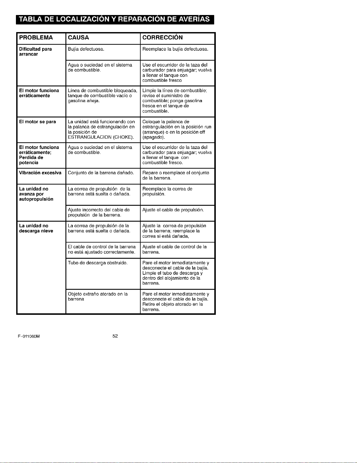
II f_,1:] mL,II _]:11m[o[o__,1mlVL,_o,][o]_h'dl :t :1-.J_,1:r±_ [o]_I _]_±\vj _ :t r±_
PROBLEMA CAUSA CORRECCION
Dificultad para Buj_adefectuesa. Reernplace la bujia defectuesa.
arrancar
Agua o suciedad en et sistema Use el escurridor de la taza del
de combustible, carburador para enjuagar; vuelva
a Ilenar el tanque con
combustible fresco
El motor funoiona Linea de combustible bloqueada, Limpie la linea de combustible;
err_ticamente tanque de combustible vacio o revise el suministro de
gasolina afleja, combustible; ponga gasolina
fresca en el tanque de
combustible.
El motor se para La unidad est_ funcionando con Coloque la palanca de
la palanca de estrangulaci6n en estrangulaci6n en la posici6n run
la posici6n de (arranque) o en Ia posiciSn off
ESTRANGULACION (CHOKE). (apagado).
El motor funciona Agua o suciedad en et sistema Use el escurridor de la taza del
erraticamente; de combustible, carburador para enjuagar; vuelva
Perdida de a Ilenar el tanque con
)otencia combustible fresco.
Vibracion excesiva Conjunto de Ia barrena dar_ado. Repare o reemplace el conjunto
de la barren&
La unidad no La correa de propulsi6n de la Reemplace la correa de
avanza por barrena est_ suelta o daflada, propulsi6n.
autopropulsion
Ajuste incorrecto del cable de Ajuste el cable de propulsi6n.
propulsi6n de la barren&
La unidad no La correa de propulsi6n de la Ajuste la correa de propulsi6n
descarga nieve barrena est_ suelta o daflada, de la barrena; reemplace la
correa siesta daSada,
El cable de control de Ia barrena Ajuste el cable de control de la
no est_ ajustado correctamente, barren&
Tubo de descarga obstruido. Pare el motor inmediatamente y
desconecte el cable de la bujia.
Limpie el tubo de descarga y
dentro del alojamiento de la
barren&
Objeto extraSo atorado en la
barrena
Pare el motor inmediatamente y
desconecte el cable de la buj_a,
Retire el objeto atorado en la
barrena.
F-011060M 52
SEARS, ROEBUCK AND CO.
Garantia limitada de cumplimiento con el Sistema Federal
de control de emisiones y con el sistema de control de
emisiones del Estado de California
Motores pequehos no aptos para carretera (off-road)
CONTROL DE EMISIONES DE
CALIFORNIA Y DE LA AGENCIA DE
PROTECCI(_N AMBIENTAL (EPA) DE
E.U.A. - DECLARACI(_N DE LA
GARANTIA
La Agencia de Protecci6n Ambiental de los
Estados Unidos (en Io sucesivo "EPA"), el
Consejo de California para los Recursos del
Aire (en Io sucesivo "CARB") y Sears, Roe-
buck and Co. tienen el placer de explicar Ioque
es la Garantla Federal y de California para Sis-
temas de Control de Emisiones de su nuevo
motor pequeSo para vehiculos off-road. En
California, los motores pequeflos paravehicu-
los off-road de modelo 1995 y modelos de
aSos posteriores deben set disefiados, cons-
truidos y equipados para cumplir con las es-
trictas normas anti contaminaci6n del Estado.
En otros estados, los motores modelo 1997 y
modelos de aflos posteriores deben estar di-
seflados, construidos y equipados, al momen-
to de su venta, para que cumpIan con las
disposiciones de la EPA acerca de motores
pequeSos para vehiculos off-road. Sears,
Roebuck and Co. garantizarA el sistema para
el control de emisiones de su motor pequefio
para vehiculos off-road por los periodos de
tiempo que se mencionan mas adelante, con
tal que su motor pequefio para vehiculos off-
road no haya sufrido algSn abuse, negligen-
cia, modificaci6n no aprobada o
mantenimiento indebido.
Es probable que su sistema para el control de
emisiones incluya partes como el carburador,
el sistema de encendido y el sistema de esca-
pe. Tambien es posible que se incluya el siste-
ma de descompresiSn y otros ensamblajes
relacionados con emisiones.
Cuando surja una condici6n protegida per la
garantia, Sears, Roebuck and Co. reparara su
motor pequeSo para vehiculos off-road sin
costo alguno para usted pot concepto de diag-
n6stico, partes y mano de obra.
SISTEMA PARA EL CONTROL DE
EMISIONES DEL FABRICANTE -
COBERTURA DE LA GARANTIA
Los sistemas para el control de emisiones mo-
delo 1995 y modelos de aflos posteriores de
motores pequeflos paravehfculos off-road en
California estAn garantizados per dos aSos, tal
y como se menciona en la presente garantia.
En otros estados, los motores modelo t 997 y
modelos de aflos posteriores tambien estan
garantizados pot dos a_os. En caso de que,
durante dicho periodo de la garantia, cualquier
parte de su motor relacionada con emisiones
este defectuosa en sus materiales o hechura,
Sears, Roebuck and Co. reparara o cambiarA
dicha parte.
RESPONSABILIDADES DEL
PROPIETARIO DE LA GARANTJA
Como propietario del motor pequeAo para ve-
hiculos off-road usted es responsable de que
se Ileve a cabo el mantenimiento requerido
que se menciona en el Manual del Propietario,
pero Sears, Roebuck and Co. no negara la ga-
rantia 5nicamente debido a lafalta de un reci-
boo a que usted no proporcione una prueba
escrita de que se ha Ilevado a cabo el manteni-
miento programado.
No obstante, usted, como propietario del mo-
tor pequefio para vehiculos off-road, debera
estar consciente de que Sears, Roebuck and
Co. le puede negar la cobertura de la garantia
si su motor oalg unaparte del mismo hafallado
debido aun abuso, negligencia, mantenimien-
to inadecuado o modificaciones no aproba-
das.
Usted es responsable de presentar su motor
pequeflo para vehiculos off-road en el Taller
Autorizado de Servicio de Sears, Roebuck
and Co. en cuanto surja el problema. Las repa-
raciones bajo la garantia deben Ilevarse a ca-
bo dentro de un periodo de tiempo razonable
que no exceda de 30 dias.
Se puede programar el servicio de garantia
Ilamando al Taller Autorizado de Servicio de
F-011060M 53
Sears, Roebuck and Co. o a Sears, Roebuck
and Co. al 1-800-473-7247 (llamada gratuita
en E.U.A.).
NOTA IMPORTANTE
Esta declaraci6n de la garantia explica los de-
rechos y las obligaciones que usted tiene de
conformidad con la Garantia del Sistema para
el Control de Emisiones (en Io sucesivo la"Ga-
rantia SCE"), la cual Sears, Roebuck and Co.
Ie proporciona de conformidad con las leyes
de California. V6ase tambien las Garantias Li-
mitadas de Sears, Roebuck and Co. que se
adjuntan a la Garantia SCE en una hoja por
separado y que tambien le proporciona Sears,
Roebuck and Co. La Garant[a SCE t_nicamen-
te se aplica en el sistema para el control de
emisiones de su motor nuevo. Hasta el punto
en donde no haya ning_n conflicto en terminos
entre la Garantia SCE y la Garantia de Sears,
Roebuck and Co., la Garantla SCE aplicar_
para cualquier circunstancia a excepci6n de
aquella en que la Garantia de Sears, Roebuck
and Co. pueda proporcionar un periodo de ga-
rantia mAs largo. La Garantia SCE y la Garan-
tim de Sears, Roebuck and Co. describen
importantes derechos y obligaciones que us-
ted tiene con respecto a su motor nuevo.
S61o se puede Ilevar a cabo el servicio de ga-
rantia en un Taller Autorizado de Servicio de
Sears, Roebuck and Co. AImomento de solici-
tar un servicio de garantia, se debe presentar
una prueba de la feche de compra por parte
del comprador original. El comprador pagarA
cualquier cargo pot concepto de Ilamadas de
servicio y/o transportaci6n de productos des-
de y para el lugar en donde se Ileve a cabo el
trabajo de inspecci6n y/o garantia. El compra-
dor sera responsable de cualquier da_o o per-
dida en el que se incurra con relaci6n a la
transportaci6n de cualquier motor o cualquier
parte del mismo que se presente para inspec-
ci6n y/o trabajo de garantia.
Si tiene alg una preg unta con relaci6n a sus de-
rechos y responsabilidades, debera Ilamar a
Sears, Roebuck and Co. al 1-800-473-7247.
GARANTiA DEL SISTEMA PARA EL
CONTROL DE EMISIONES
Garantia del Sistema para et Control de Emi-
siones ("Garantia SCE") de motores peque-
Los para vehiculos off-road modelo 1995 y
modelos de aSos posteriores en California
(para otros estados, motores modelo 1997 y
aflos posteriores):
F-011060M
54
A. CAMPO DE APLICAOION: Esta garantia
deberA aplicarse a los motores peq ue5os para
vehiculos off-road modelo 1995 y modelos de
aSos posteriores en California (para otros es-
tados, motores modelo 1997 y modelos de
aSos posteriores). El Periodo de la Garantia
SCE iniciarA en la fecha de entrega del nuevo
motor o equipo al comprador original y conti-
nuara durante ios siguientes 24 meses conse-
cutivos.
B. COBERTURA GENERAL DE LA GA-
RANTiA DEL SISTEMA PARA EL CON-
TROL DE EMISIONES: Sears, Roebuck and
Co. garantiza al comprador original del nuevo
motor o equipo y a cada comprador subse-
cuente que su motor pequeflo para vehiculos
off-road est.:
1. Dise_ado, construido y equipado para que
cumpla con todas las disposiciones aplicables
adoptadas por el Consejo para los Recursos
del Aire de conformidad con su autoridad es-
pecificada en los Cap[tulos 1 y 2, Parte 5, Divi-
si6n 28 del C6digo de Salud y Seguridad, y
2. Libre de defectos en sus materiales y mano
de obra, los cuales, en cualquier momento du-
rante el Periodo de la Garantla SCE, cause la
falla de una parte reIacionada con emisiones
y que est_ bajo la garantia en cuanto a que no
sea identica en sus materiales a la parte des-
crita en la solicitud de motor dei fabricante pa-
ra su certificaci6n.
C. La Garantia SCE s61oafafle alas partes de
su motor relacionadas con emisiones de la si-
guiente manera:
1. Cualquier parte relacionada con emisiones
que no se especifique como de cambio, tal y
como se requiere en el mantenimiento especi-
ficado en el Manual del Propietado, debera ga-
rantizarse pot el Periodo de la Garantia SCE.
Si dicha parte falla durante el Periodo de la Ga-
rantia SCE, Sears, Roebuck and Co. la repa-
rata o cambiara de acuerdo con la Subsecci6n
4 que se menciona mas adelante. Cualquier
parte reparada o cambiada de conformidad
con la Garantia SCE deberA estar garantizada
pot el resto del Periodo de la misma.
2. Cualquier parte garantizada y relacionada
con emisiones que est_ especificada s61o pa-
ra inspecciones regulares conforme al Manual
del Propietario deberA estar garantizada pot el
Periodo de la Garantia SCE. Una declaraci6n
en dichas instrucciones pot escrito a efecto de
"reparar o oambiar tal y como sea necesario"
no reducirA el Periodo de la Garantia SCE. Di-
cha parte reparada o cambiada conforme a la
GarantiaSCEdeberAgarantizarseperelresto
delPeriododelamisma.
3.CualquierpartegarantizadayreIacionada
conemisionesqueseespecifiqueparacam-
bio,deconformidadconelManualdelPropie-
tario,deber&garantizarseporelperiodode
tiempoprevioalprimerpuntodecambiode
esaparte.Silapartefallaantesdelprimer
cambioprogramado,Sears,RoebuckandCo.
repararAocambiaraesapartedeacuerdocon
laSubsecci6n4quesemencionamasadelan-
te.Cualquierparterelacionadaconemisiones
queserepareocambiedeconformidadconla
GarantiaSCEdeberAestargarantizadaporel
restodetPeriododelamismaprevioalprimer
puntodecambioprogramadodeesapartere-
iacionadaconemisiones.
4.Lareparaci6noelcambiodecualquierparte
garantizadayrelacionadaconemisionesde
conformidadconestaGarantlaSCEsedebe-
rAIlevaracabo,sincargoalgunoparaelpro-
pietario,enunTallerAutorizadodeServiciode
Sears,RoebuckandCo.
5.Nosecargaraalpropietarioelcostopertra-
bajodediagn6stico,elcualIlevaaladetermi-
naci6ndequeunaparteprotegidapotla
GarantiaSCEsiest_defectuosa,provistoque
dichotrabajodediagn6sticoseIleveacaboen
unTallerAutorizadodeServiciodeSears,
RoebuckandCo.
6.Sears,RoebuckandCo.seraresponsable
dedaSosaotroscomponentesoriginalesdel
motoromodificacionesaprobadasqueproba-
blementeseancausadospotunafallacom-
prendidaen la garantiade unaparte
relacionadaconemisionescubiertaporlaGa-
rantiaSCE.
7.DuranteelPeriododelaGarant[aSCE,
Sears,RoebuckandCo.deberAconservarun
suministrodepartesgarantizadasyrelaciona-
dasconemisionesqueseasuficientepara
cumplirlademandaesperadadeesaspartes
relaoionadasconemisiones.
8.Sepuedeutilizarcualquierpartederepues-
torelacionadaconemisionesautorizaday
aprobadaperSears,RoebuckandCo.para
utilizarseeneldesempeflodecualquierman-
tenimientoocambiodelaGarantiaSCE,la
cualseproporcionarAsincargoalgunoparael
propietario.DichousonoreducirAlasobliga-
cionesdeSears,RoebuckandCo.conforme
alaGarantiaSCE.
9.Laspartesqueseagreguenomodifiquen
sinaprobaci6nnosepodranutilizarparamo-
dificarorepararunmotordeSears,Roebuck
andCo.DichousoanulaestaGarant[aSCEy
conformar_lasbasessuficientespararecha-
zarlademandadeunaGarantiaSCE.Sears,
RoebuckandCo.noseraresponsable,con-
formeaestagarantla,porlasfallasdecual-
quierpartegarantizadadeunmotordeSears,
RoebuckandCo.causadaspotelusodedi-
chaparteagregadaomodificadasinaproba-
ci6n.
LAS PARTES RELACIONADAS CON
EMISIONES INCLUYEN A LAS
SIGUIENTES:
1. Ensamblaje deI carburador y sus compo-
nentes intemos
a) Filtro de combustible
b) Empaques (juntas) del carburador
c) Tubo de entrada
2. Ensamblaje del depurador de aire
a) Elemento del filtro de aire
3. Sistema de encendido, que incluye:
a) Buj_a de encendido
b) M6dulo de encendido
c) Ensamblaje del volante
4. Silenciador catalitico (si est_ equipado)
a) Empaque del silenciador (siesta equipado)
b) Colector de escape (siesta equipado)
5. Ensamblaje del respiradero del carter del ci-
gL_eSaly sus componentes
a) Tubo de conexi6n deI respiradero
10/22/99 EPA/CARB
Sears, Roebuck and Co., Hoffman Estates, Ib 60179 U.S.A.
F-011060M 55
For repair of major brand appliances in your own home.,.
no matter who made it, no matter who sold it!
iiiiiiiiiii
1-800-4-MY-HOME SMAny,_medayor night
(,-800469-4663!
iiiiiiiiiii
www.sears.com
iiiiiiiiiii
TO bring in products such as vacuums,
lawn equipment and electronics for repair, call for
the location of your nearest Sears Parts & Repair Center.
1-800-488-1222 Anytime, day or night
www.sears.com
Fortherep,acementpa_s,accessoriesandownersmanuals
that you need to do-it-yourself, call Sears PartsDirectSM!
iiiiiiiiiii
1-800-366-PART 6a.m.-11p.m.CST,
(,.soo.306-72,s 7d ysaweek
iiiiiiiiiii
www.sears.com/partsdirect
TO purchase or inquire about a Sears Service Agreement:
iiiiiiiiiii
1-800-827-6655
iiiiiiiiiii
7 a.m.- 5 p.m. OST_ MOFL- Sa,.
® Registered Trademark / TM Trademark of Sears, Roebuck and Co,
TM
© Sears, Roebuck and Co ® Marca Registrada / Marca de Fabrica de Sears, Roebuck and Co
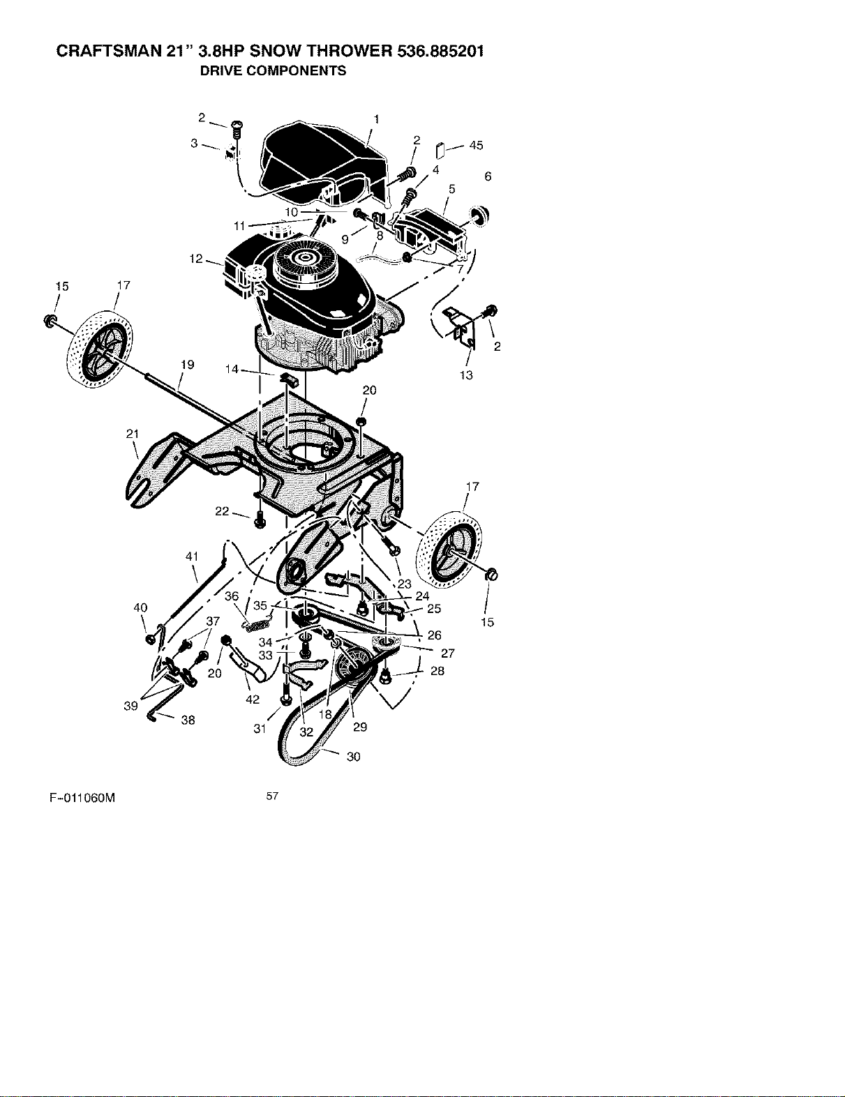
CRAFTSMAN 21" 3.8HP SNOW THROWER 536.885201
DRIVE COMPONENTS
1
2
_t 45
4 6
5
15 17
/ /
21
19
2O
/
13
17
4O
\
39
41
38
42
/
31
29
30
27
28
/
15
F-O11060M 57
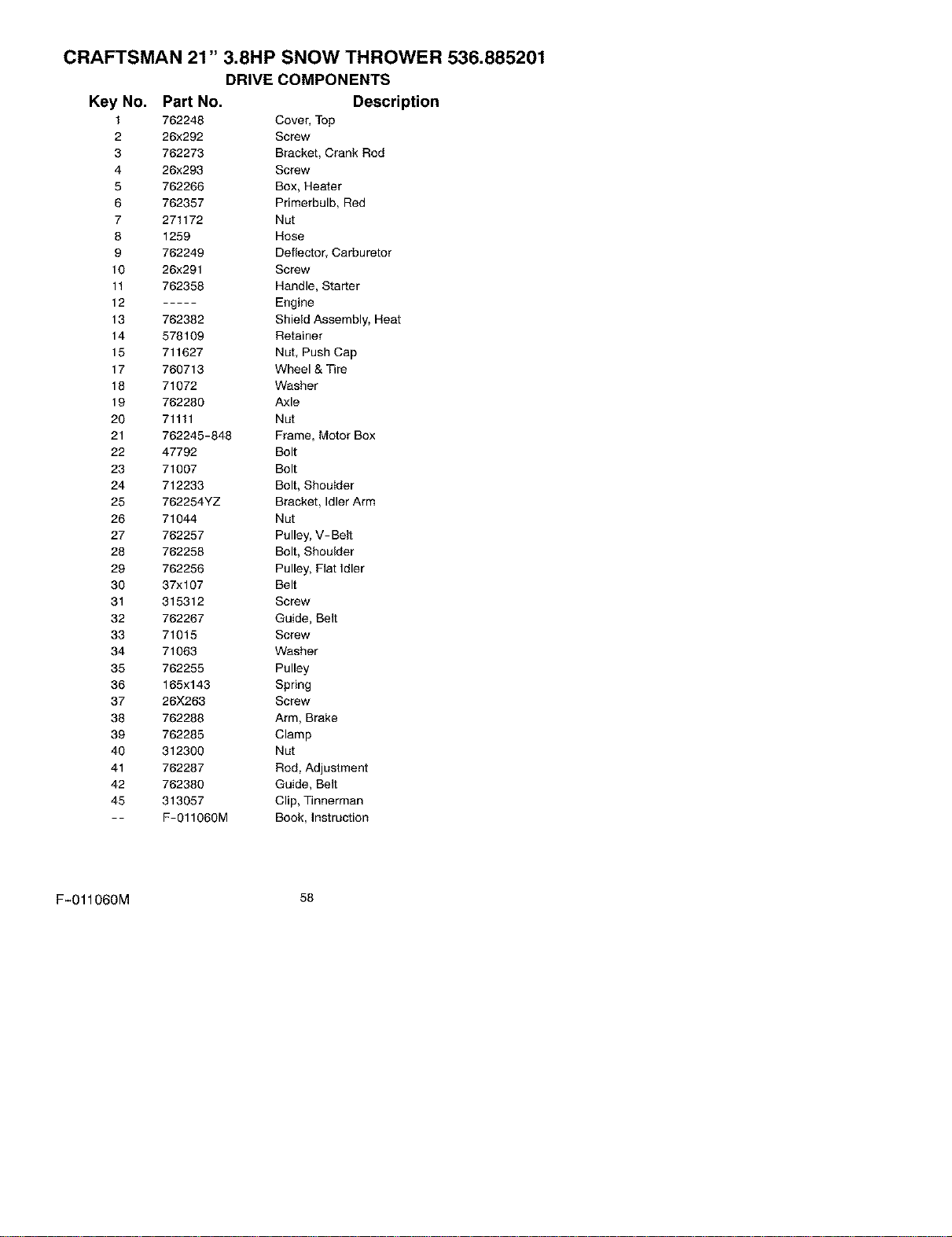
CRAFTSMAN 21" 3.8HP SNOW THROWER 536.885201
DRIVE COMPONENTS
Key No. Part No. Description
1 762248 Cover, Top
2 26x292 Screw
3 762273 Bracket, Crank Rod
4 26x293 Screw
5 762266 Box, Heater
6 762357 Primerbulb, Red
7 271172 Nut
8 1259 Hose
9 762249 Deflector, Carburetor
10 26x291 Screw
11 762358 Handle, Starter
12 ..... Engine
13 762382 Shield Assembly, Heat
14 578109 Retainer
15 711627 Nut, Push Cap
17 760713 Wheel & Tire
18 71072 Washer
19 762280 Axle
20 71111 Nut
21 762245-848 Frame, Motor Box
22 47792 Bolt
23 71007 Bolt
24 712233 Bolt, ShouIder
25 762254YZ Bracket, Idler Arm
26 71044 Nut
27 762257 Pulley, V-Belt
28 762258 Bolt, Shoulder
29 762256 Pulley, Flat Idler
30 37xl 07 Belt
31 315312 Screw
32 762267 Guide, Belt
33 71015 Screw
34 71063 Washer
35 762255 Pulley
36 165x143 Spring
37 26X263 Screw
38 762288 Arm, Brake
39 762285 Clamp
40 312300 Nut
41 762287 Rod, Adjustment
42 762380 Guide, Belt
45 313057 Clip, Tinnerman
- - F-O1106OM Book, Instruction
F-O11060M 58
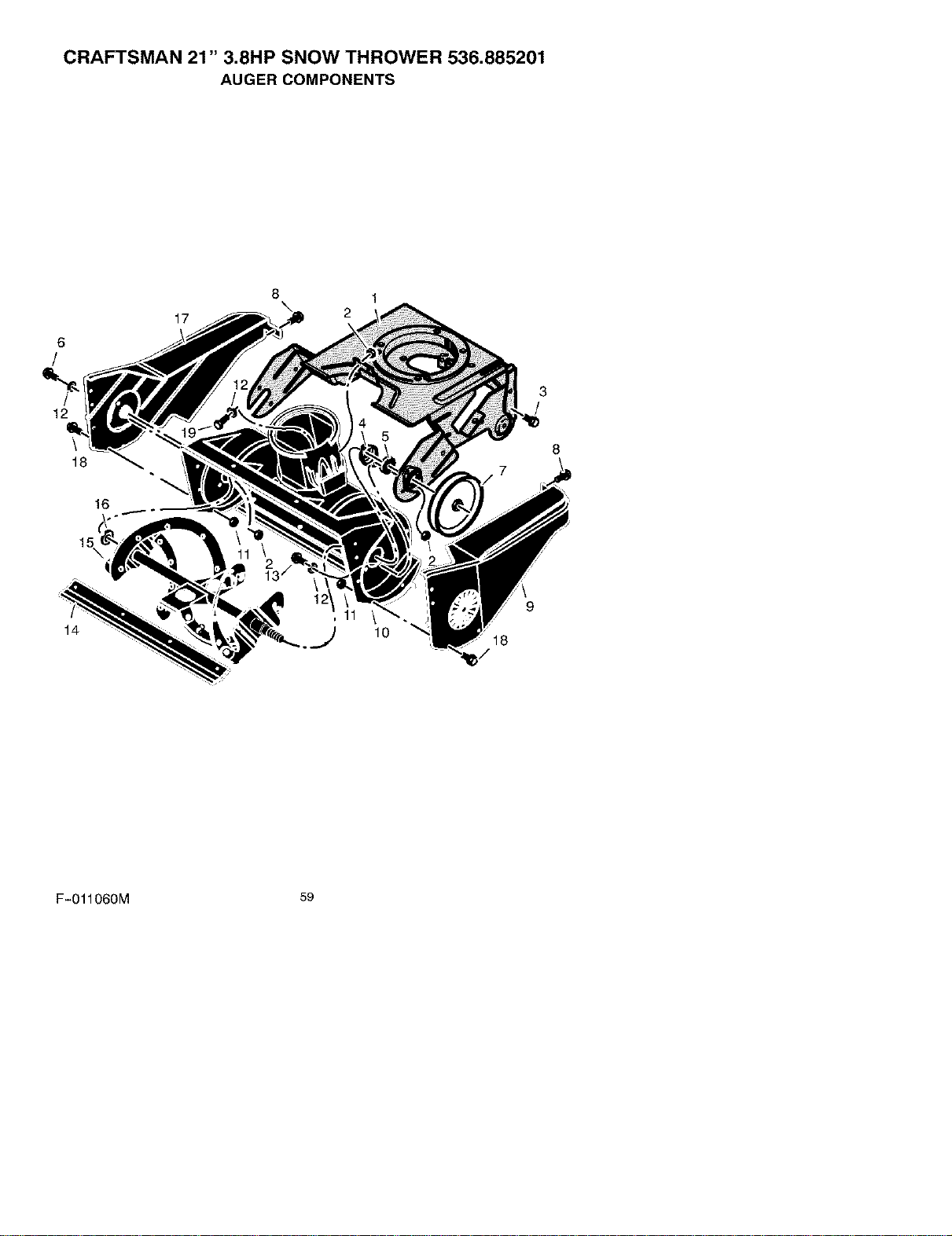
CRAFTSMAN 21" 3.8HP SNOW THROWER 536.885201
AUGER COMPONENTS
6
/
12
\
18
17
1
2
3
/
8
16
14
10
9
18
F-O11060M 59
CRAFTSMAN 21" 3.8HP SNOW THROWER 536.885201
AUGER COMPONENTS
Key No. Part No. Description
1 762246-848 Frame, Motor Box
2 302635 Nut
3 710079 Bolt
4 580251 Retainer, Bearing
5 43846 Bearing
6 302628 Bolt
7 338965 Pulley, Auger
8 710274 Screw
9 762277 Cover, Left Belt
10 762266 Housing, Auger
11 312300 Nut
12 71067 Washer
13 579052 Bolt
14 55323 Blade, Scraper
15 327072 Auger Assembly
16 580969 Washer
17 762276 Cover, Right
18 12342 Screw
19 302626 Screw
F-O11060M 60
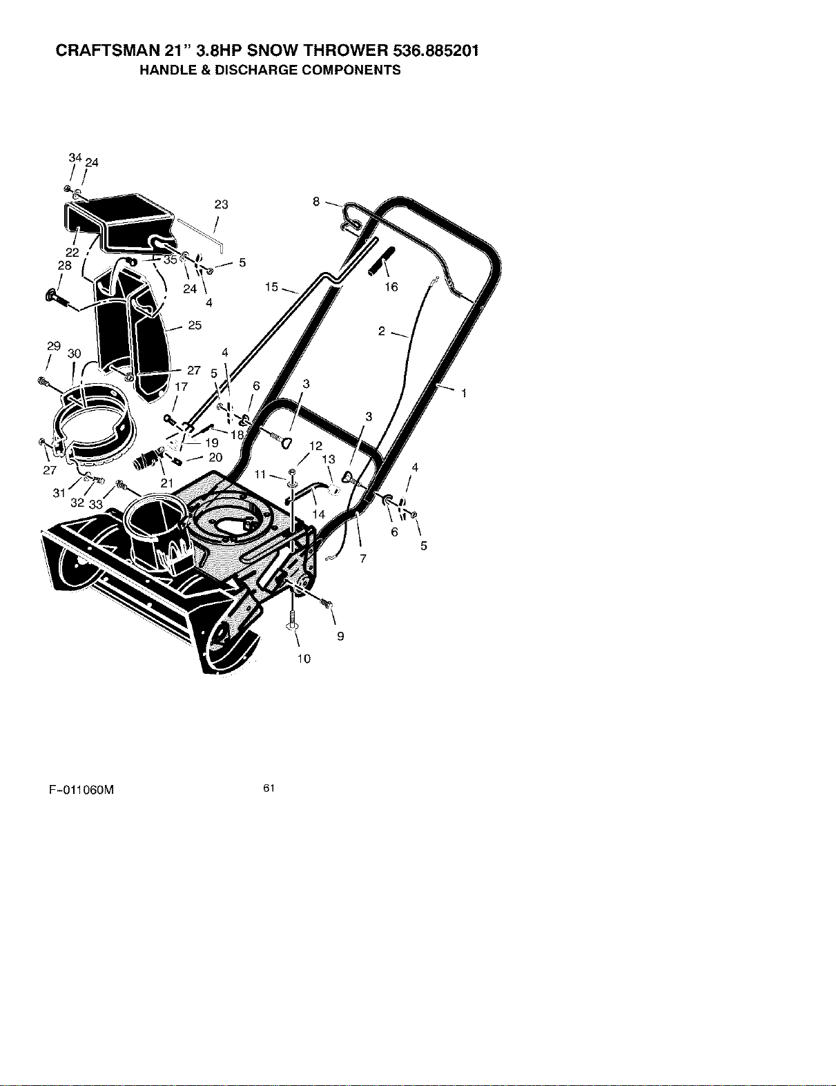
CRAFTSMAN 21" 3.8HP SNOW THROWER 536.885201
HANDLE & DISCHARGE COMPONENTS
22
28
23
/
29
/
27
31
4
/
6
5
7
9
10
F-O11060M 61
CRAFTSMAN 21" 3.8HP SNOW THROWER 536.885201
HANDLE & DISCHARGE COMPONENTS
Key No. Part No. Description
1 762252-853 Handle, Upper
2 762259 Cable, Auger Drive
3 337584 Bolt
4 57171 Knob
5 71037 Nut
6 311936 Washer
7 762250-853 Handle, Lower
8 762251-853 Lever, Auger Drive
9 70984 Screw
10 340715 Bolt
11 712123 Washer
12 780029 Nut
13 762281 Bushing, Tensioner
14 762282 Bracket, Cable Tensioner
15 762362YZ Rod, Crank
16 762289 Grip, Crank Rod
17 578309 Pin, Clevis
18 579493 Pin, Cotter
19 578063 Block, Universal Pivot
20 578060 Pin
21 585196 Gear, Worm
22 325847 Deflector
23 308931 Pin, Pivot
24 71071 Washer
25 334234 Chute, Discharge
27 302635 Nut
28 302843 Bolt
29 313686 Bolt
30 762286 Ring, Chute
31 71067 Washer
32 302628 Bolt
33 70984 Bolt
34 71391 Locknut
35 578088 Bolt
F-011060M 62
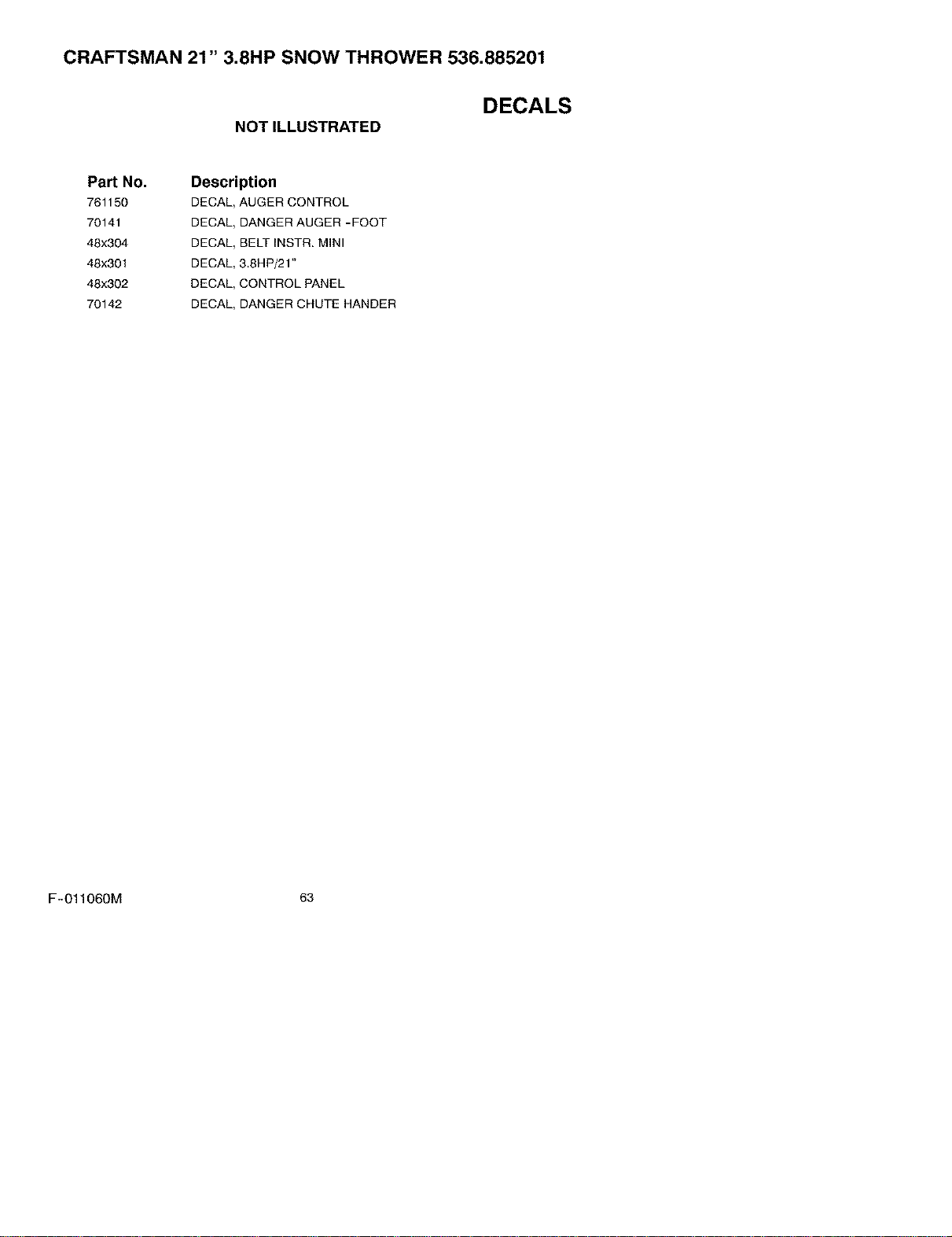
CRAFTSMAN 21" 3.8HP SNOW THROWER 536.885201
NOTILLUSTRATED
DECALS
Part No.
761150
70141
48x304
48x301
48x302
70142
Description
DECAL, AUGER CONTROL
DECAL, DANGER AUGER -FOOT
DECAL, BELT INSTR. MINI
DECAL, 3.8HP/21"
DECAL, CONTROL PANEL
DECAL, DANGER CHUTE HANDER
F-O11060M 63
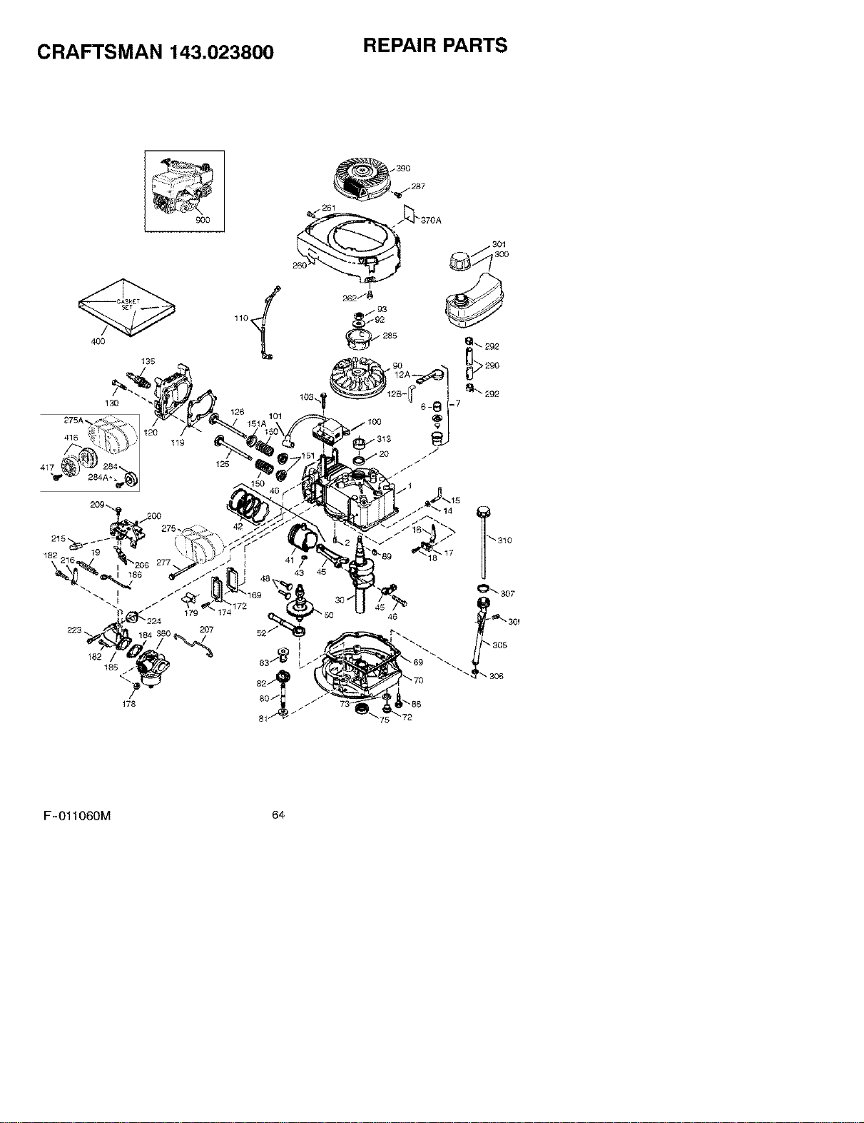
CRAFTSMAN 143.023800 REPAIR PARTS
900
178
182
185
/ 93
285
_172
2O7
F-O11060M 64
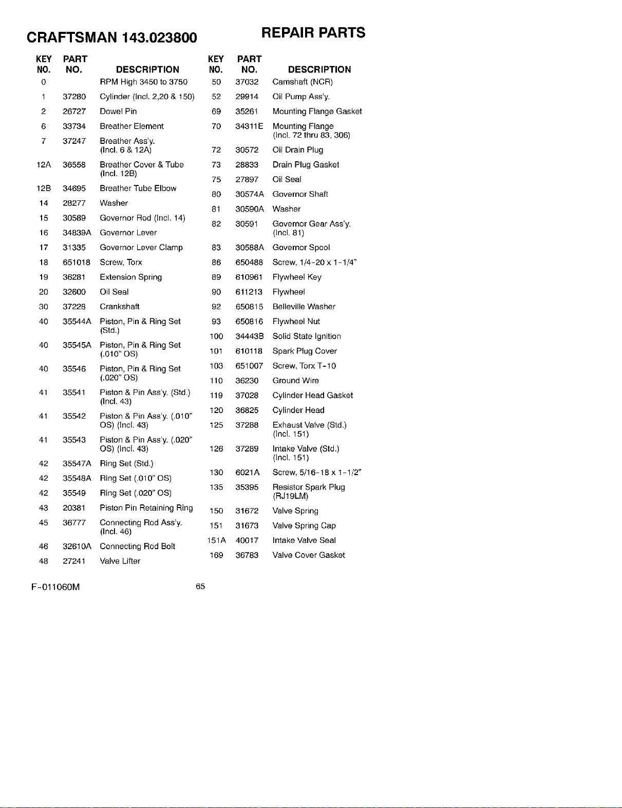
CRAFTSMAN 143.023800
KEY PART
NO. NO. DESCRIPTION
0 RPM High 3450 to 3750
1 37280 Cylinder (Incl. 2,20 & t 50)
2 26727 Dowel Pin
6 33734 Breather Element
7 37247 Breather Ass'y.
(Incl. 6 & 12A)
12A 36558 Breather Cover & Tube
(Incl. 12B)
12B 34695 Breather Tube Elbow
14 28277 Washer
15 30589 Governor Rod (Incl. 14)
16 34839A Governor Lever
17 31335 Governor Lever Clamp
18 651018 Screw, Torx
19 36281 Extension Spring
20 32600 Oil Seal
30 37228 Crankshaft
40 35544A Piston, Pin & Ring Set
(Std,)
40 35545A Piston, Pin & Ring Set
(,0t 0" OS)
40 35546 Piston, Pin & Ring Set
(,020" OS)
41 35541 Piston & Pin Ass'y. (Std.)
(Incl. 43)
41 35542 Piston & Pin Ass'y. (,010"
OS) (Ind. 43)
41 35543 Piston & Pin Ass'y. (.020"
OS) (Ind. 43)
42 35547A Ring Set (Std.)
42 35548A Ring Set (,010" OS)
42 35549 Ring Set (.020" OS)
43 20381 Piston Pin Retaining Ring
45 36777 Connecting Rod Ass'y.
(Incl. 46)
46 326t0A Connecting Rod Boit
48 27241 Valve Lifter
REPAIR PARTS
KEY PART
NO. NO. DESCRIPTION
50 37032 Camshaft (NCR)
52 29914 Oil Pump Ass'y.
69 35261 Mounting Flange Gasket
70 34311E Mounting Flange
(Incl. 72 thru 83,306)
72 30572 Oil Drain Plug
73 28833 Drain Plug Gasket
75 27897 Oil Seal
80 30574A Governor Shaft
81 30590A Washer
82 30591 Governor Gear Ass'y.
(Incl. 81)
83 30588A Governor Spool
86 650488 Screw, 1/4-20 x 1-1/4"
89 610961 Flywheei Key
90 611213 Flywheel
92 650815 Belleville Washer
93 650816 Flywheel Nut
t00 34443B Solid State Ignition
101 610118 Spark Plug Cover
103 651007 Screw, Torx T-t 0
110 36230 Ground Wire
119 37028 Cylinder Head Gasket
t 20 36825 Cylinder Head
t 25 37288 Exhaust Valve (Std.)
(Incl. 151)
t 26 37289 Intake Valve (Std,)
(Incl. 151)
130 6021A Screw, 5/16-18 x 1-1/2"
t35 35395 Resistor Spark Plug
(RJt9LM)
150 31672 Valve Spring
151 31673 Valve Spring Cap
151A 40017 Intake Valve Seal
t 59 35783 Valve Cover Gasket
F-011060M 65
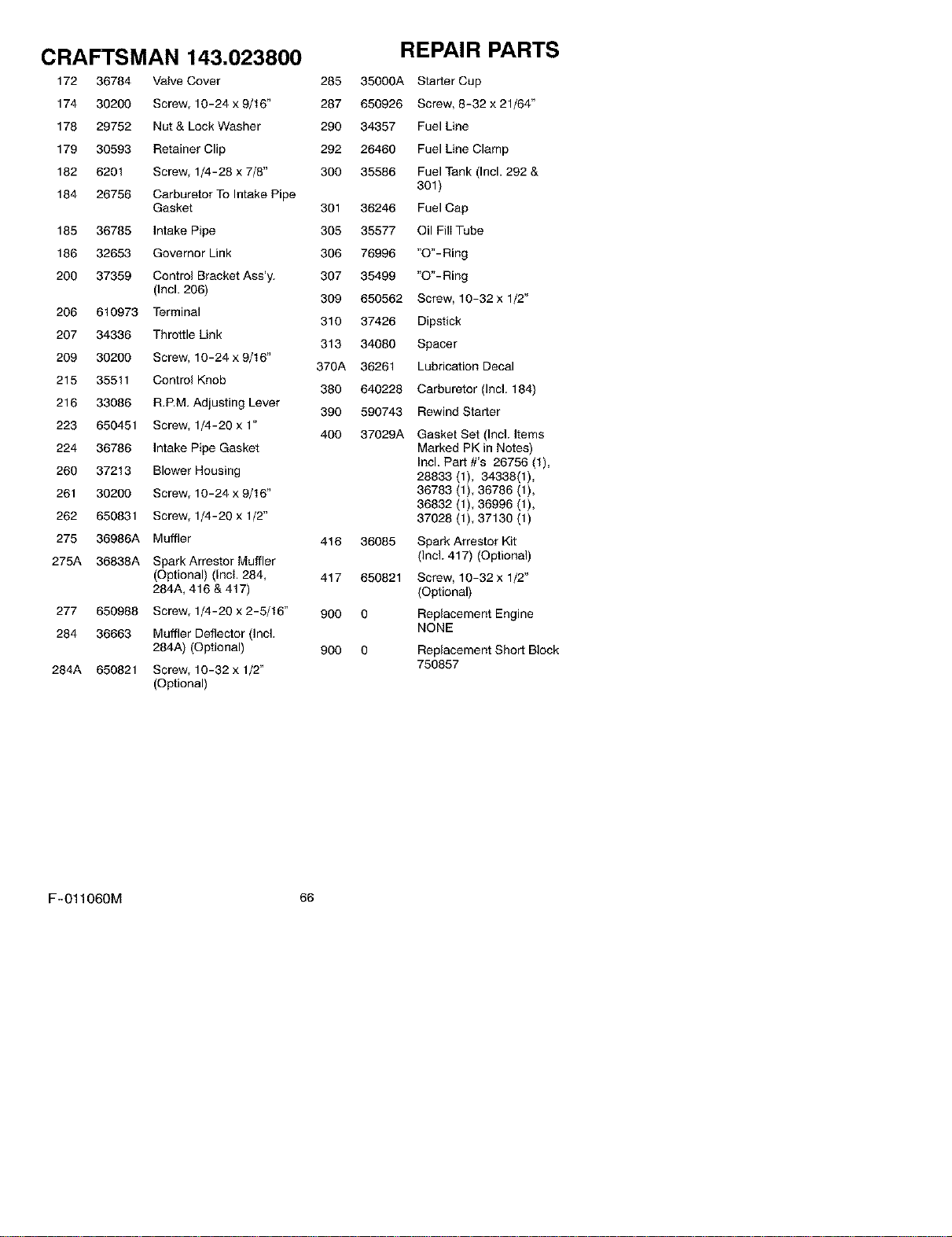
CRAFTSMAN 143.023800 REPAIR PARTS
172 36784 VaNe Cover 285 35000A Starter Cup
174 30200 Screw, 10-24 x 9/16" 287 650926 Screw, 8-32 x 21/64"
178 29752 Nut & Lock Washer 290 34357 Fuel Line
179 30593 Retainer Clip 292 26460 Fuel Line Clamp
182 6201 Screw, 1/4-28 x 7/8" 300 35586 Fuel Tank (Incl. 292 &
301)
184 26756 Carburetor To Intake Pipe
Gasket 301 36246 Fuel Cap
185 36785 Intake Pipe 305 35577 Oil Fill Tube
186 32653 Governor Link 306 76996 "O"- Ring
200 37359 Control Bracket Ass'y. 307 35499 "O"-Ring
(Incl. 206)
309 650562 Screw, 10-32 x 1/2"
206 610973 Terminal
310 37426 Dipstick
207 34336 Throttle Link
313 34080 Spacer
209 30200 Screw, 10-24 x 9/16"
370A 36261 Lubrication Decal
215 35511 Control Knob
380 640228 Carburetor (Incl. 184)
216 33086 R.P.M. Adjusting Lever
390 590743 Rewind Starter
223 650451 Screw, 1/4-20 x 1"
400 37029A Gasket Set (Incl. Items
224 36786 Intake Pipe Gasket Marked PK in Notes)
Incl. Part #'s 26756 (1),
260 37213 Blower Housing 28833 (1), 34338(1),
261 30200 Screw, 10-24 x 9/16" 36783 (1), 36786 (1),
36832 (1), 36996 (1),
262 650831 Screw, 1/4-20 x 1/2" 37028 (1), 37130 (1)
275 36986A Muffler 416 36085 Spark Arrestor Kit
275A 36838A Spark Arrestor Muffler (Incl. 417) (Optional)
(Optional) (Incl. 284, 417 650821 Screw, 10-32 x 1/2"
284A, 416 & 417) (Optional)
277 650988 Screw, 1/4-20 x 2-5/16" 900 O Replacement Engine
284 36663 Muffler Deflector (Incl. NONE
284A) (Optional) 900 O Replacement Short Block
284A 650821 Screw, 10-32 x 1/2" 750857
(Optional)
F-011060M 66
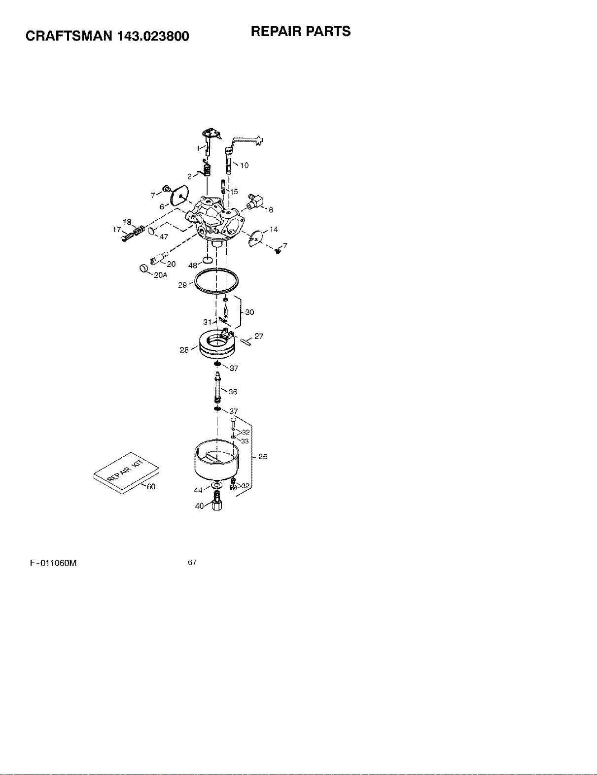
CRAFTSMAN 143.023800 REPAIR PARTS
F-O11060M 67
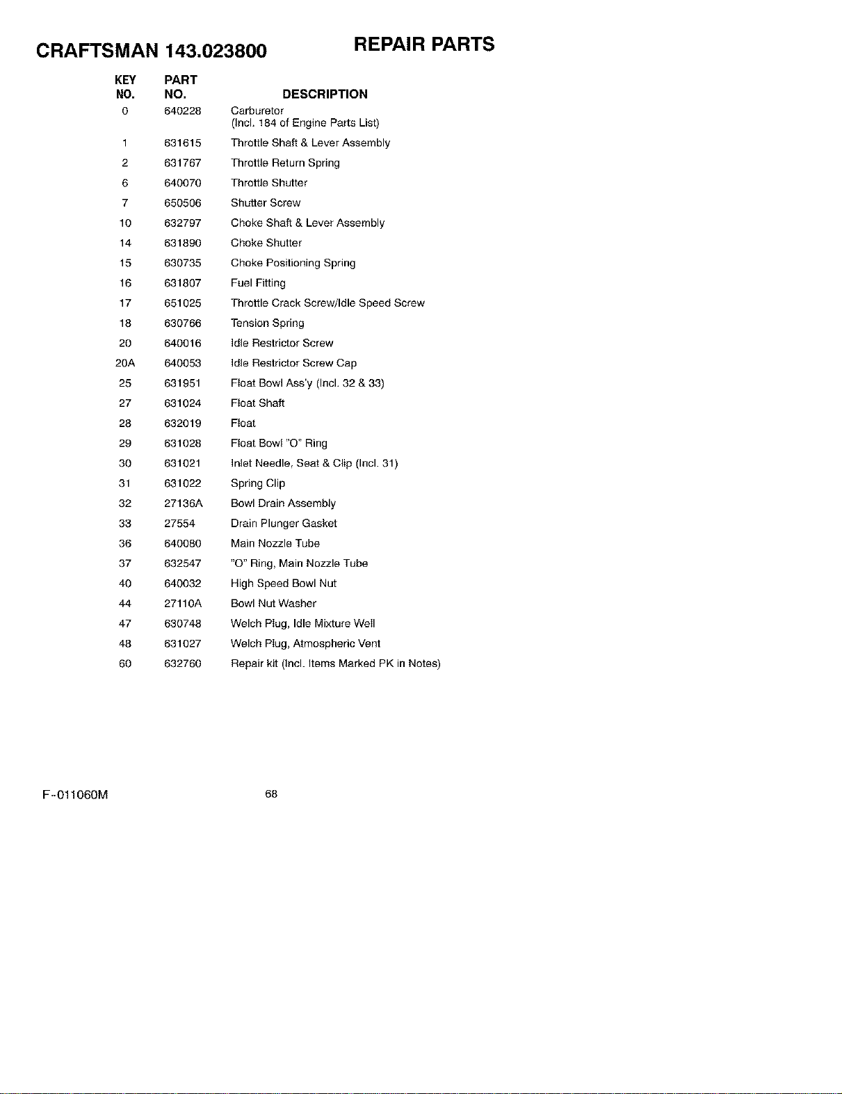
CRAFTSMAN
KEY PART
NO. NO.
O 640228
1
2
6
7
10
14
15
16
17
18
20
20A
25
27
28
29
30
31
32
33
36
37
40
44
47
48
60
143,023800
REPAIR PARTS
DESCRIPTION
Carburetor
(Incl. 184 of Engine Parts List)
631615 Throttle Shaft & Lever Assembly
631767 Throttle Return Spring
640070 Throttle Shutter
650506 Shutter Screw
632797 Choke Shaft & Lever Assembly
631890 Choke Shutter
630735 Choke Positioning Spring
631807 Fuel Fitting
651025 Throttle Crack Screw/Idle Speed Screw
630766 Tension Spring
640016 Idle Restrictor Screw
640053 Idle Restrictor Screw Cap
631951 Float Bowl Ass'y (Incl. 32 & 33)
631024 Float Shaft
632019 Float
631028 Float Bowl "O" Ring
631021 Inlet Needle, Seat & Clip (Incl. 31)
631022 Spring Clip
27136A Bowl Drain Assembly
27554 Drain Plunger Gasket
640080 Main Nozzle Tube
632547 "O" Ring, Main Nozzle Tube
640032 High Speed Bowl Nut
27110A Bowl Nut Washer
630746 Welch Piug, Idle Mixture Weil
631627 Welch Piug, Atmospheric Vent
632760 Repair kit (Incl. Items Marked PK in Notes)
F-011060M 68
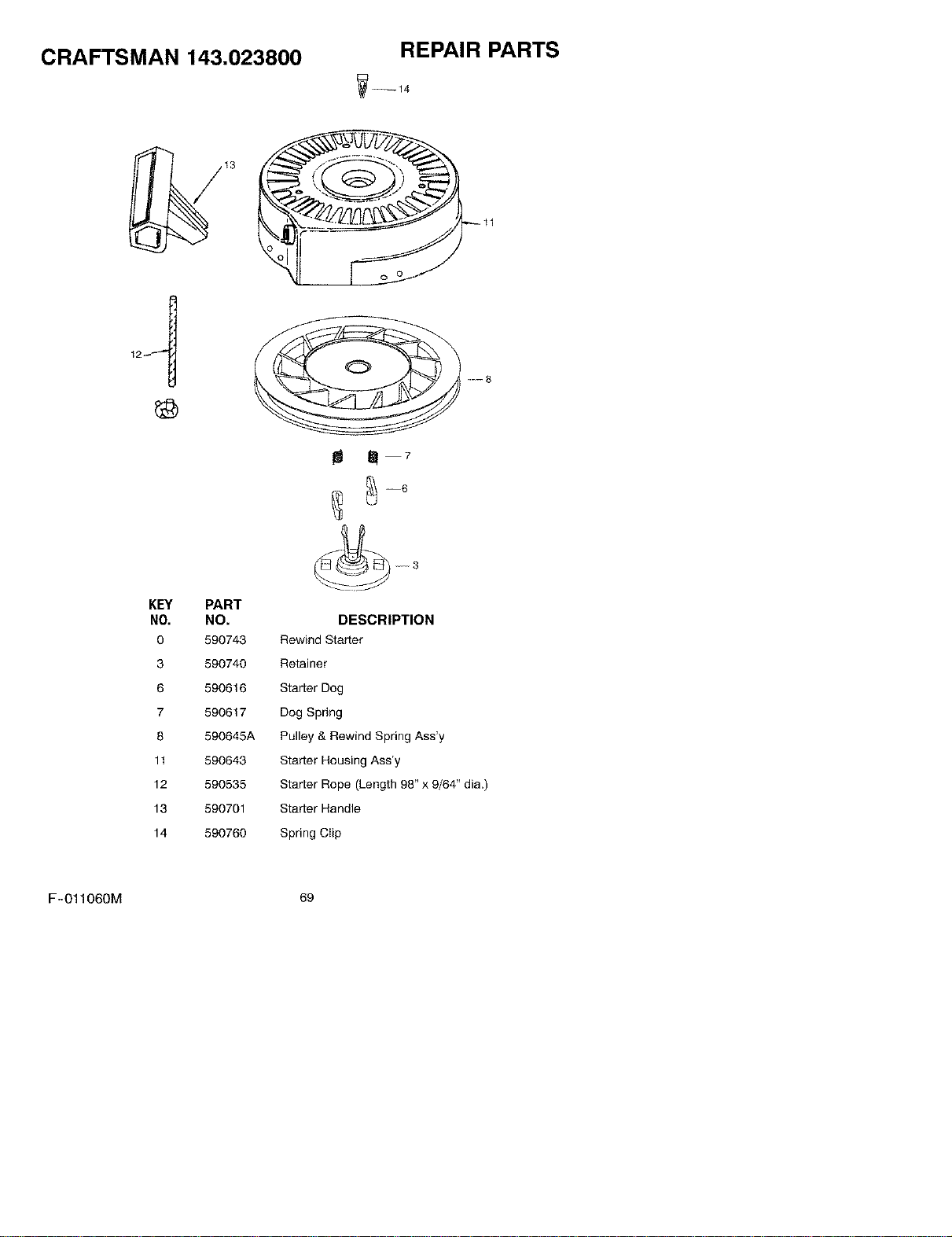
CRAFTSMAN 143.023800
REPAIR PARTS
m m 7
KEY PART
NO. NO.
0 599743
3 599740
6 590616
7 590617
8 590645A
11 590643
12 590535
13 590701
14 590760
DESCRIPTION
Rewind Starter
Retainer
Starter Dog
Dog Spring
Pulley & Rewind Spring Ass'y
Starter Housing Ass'y
Starter Rope (Length 98" x 9/64" dia.)
Starter Handle
Spring Clip
F-O11060M 69


