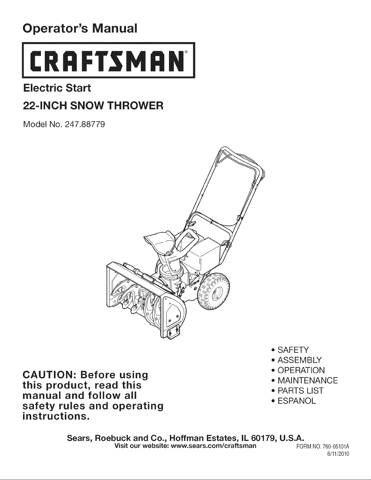
Operator's Manual
CRRFI'$1 1RN
Electric Start
22=INCH SNOW THROWER
Model No. 247.88779
CAUTION: Before using
this product, read this
manual and follow all
safety rules and operating
instructions.
o SAFETY
ASSEMBLY
OPERATION
MAINTENANCE
PARTS LIST
ESPANOL
Sears, Roebuck and Co., Hoffman Estates, IL 60179, U.S.A.
Visit our website: www.sears.com/craftsman FORMNO.769-05101A
6/11/2010
WarrantyStatement.................... Page2
SafeOperationPractices................ Page3
SafetyLabels......................... Page7
Assembly............................ Page8
Operation........................... Page12
Maintenance&Service................. Page16
Off-SeasonStorage................... Page21
Troubleshooting...................... Page22
PartsList............................ Page23
RepairProtectionAgreement............ Page35
Espa_ol............................. Page36
ContactNumbers.................. BackCover
CRAFTSMAN FULL WARRANTY
Whenoperatedand maintainedaccordingto all suppliedinstructions,if this Craftsmansnowthrowerfailsdueto a defectin materialorworkmanshipwithintwo
yearsfrom the dateof purchase,return it to any Searsstore, Sears Parts& RepairServiceCenter,orotherCraftsmanoutlet inthe UnitedStatesforfree repair(or
replacementif repairprovesimpossible).
Thiswarrantyappliesfor only90 daysfromthe dateof purchaseif this chipper-shredderis ever usedfor commercialor rentalpurposes.
This warranty covers ONLYdefects inmaterial and workmanship. Sears will NOTpay for:
• Expendableitemsthat becomewornduringnormaluse, includingbut notlimitedto
augerbladesor paddles,skidshoes,shaveplate,shear pins,sparkplug,air cleaner,belts,andoil filter.
• Standardmaintenanceservicing,oil changes,or tune-ups.
• Tire replacementor repaircausedbypuncturesfrom outsideobjects,suchas nails,thorns,stumps,orglass.
• Tire orwheel replacementor repairresultingfrom normalwear,accident,or improperoperationor maintenance.
• Repairsnecessarybecauseof operatorabuse,includingbutnotlimited to damagecaused byover-speedingthe engine,orfrom impactingobjectsthat bend
theauger,frameor crankshaft.
, Repairsnecessarybecauseof operatornegligence,includingbutnotlimitedto, electricalandmechanicaldamagecausedby improperstorage,failureto use
thepropergradeand amountof engine oil, or failureto maintaintheequipmentaccordingto the instructionscontainedinthe operator'smanual.
• Engine(fuelsystem)cleaningor repairscausedbyfuel determinedto be contaminatedor oxidized(stale).In general,fuel shouldbe usedwithin30 daysof
its purchasedate.
• Normaldeteriorationandwearof the exteriorfinishes,or productlabelreplacement.
Thiswarrantyappliesonly whilethis productis withinthe UnitedStates.
Thiswarrantygivesyou specificlegalrights,and you mayalso haveotherrightswhichvaryfromstateto state.
Sears, Roebuck and Co., Hoffman Estates, IL 60179
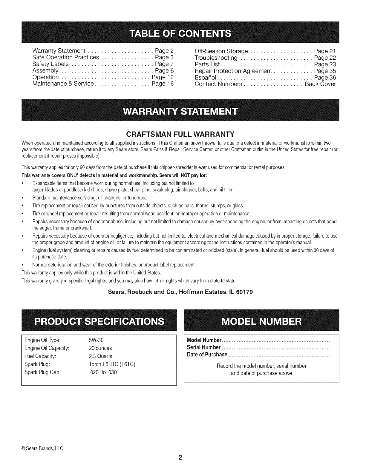
EngineOilType: 5W-30
EngineOilCapacity: 20ounces
FuelCapacity: 2.3Quarts
SparkPlug: TorchF6RTC(F6TC)
SparkPlugGap: .020"to .030"
ModelNumber.................................................................
Serial Number .................................................................
Dateof Purchase.............................................................
Recordthe modelnumber,serialnumber
anddateof purchaseabove
© Sears Brands,LLC
2
Thissymbolpointsout importantsafetyinstructionswhich,if not
followed,couldendangerthepersonalsafetyand/orpropertyof
yourselfand others. Readandfollowall instructionsin thismanual
beforeattemptingto operatethismachine.Failureto complywith
theseinstructionsmay resultin personalinjury.Whenyou seethis
symbol,HEEDITS WARNING!
CALIFORNIA PROPOSITION 65
EngineExhaust,someof itsconstituents,and certainvehicle
componentscontainoremitchemicalsknownto Stateof California
to cause cancerand birthdefectsorotherreproductiveharm,
Thismachinewasbuiltto beoperatedaccordingto the safeopera-
tion practicesin this manual.As withanytype of powerequipment,
carelessnessor error on the partof the operatorcan resultin serious
injury.Thismachineis capableof amputatingfingers,hands,toes
andfeetandthrowingdebris.Failureto observethe followingsafety
instructionscouldresultin seriousinjuryor death.
Your Responsibility--Restrict the use of this powermachineto
personswho read,understandandfollowthewarningsand instruc-
tionsin thismanualandon the machine,
SAVE THESE INSTRUCTIONS!
TRAiNiNG
• Read,understand,andfollowall instructionson the machineand
in themanual(s)beforeattemptingto assembleandoperate.
Failureto do socan resultinseriousinjuryto the operatorand/
orbystanders.Keepthis manualin a safe placeforfuture and
regularreferenceandfor orderingreplacementparts. Forques-
tionscall,1-800-4MY-HOME.
• Befamiliarwith all controlsand their properoperation.Knowhow
to stop the machineanddisengagethemquickly.
Neverallowchildrenunder14yearsof age to operatethis
machine.Children14andover shouldreadandunderstandthe
instructionsand safe operationpracticesin this manualandon
the machineandbe trainedand supervisedby an adult.
Neverallowadultsto operatethis machinewithoutproper
instruction.
• Thrownobjectscan causeseriouspersonalinjury.Planyour
snow-throwingpatternto avoiddischargeof materialtoward
roads,bystandersandthe like.
Keepbystanders,pets and childrenat least75feetfromthe
machinewhile itisin operation.Stopmachineifanyoneenters
the area.
Exercisecautionto avoidslippingor falling,especiallywhen
operatingin reverse.
PREPARATION
Thoroughlyinspectthearea wherethe equipmentis to beused.
Removeall doormats,newspapers,sleds,boards,wiresandother
foreignobjects,whichcouldbe trippedoveror thrownby the auger/
impeller.
Alwayswear safetyglassesor eyeshieldsduringoperationand
while performingan adjustmentor repairto protectyoureyes.
Thrownobjectswhich ricochetcancause seriousinjuryto the
eyes.
Donot operatewithoutwearingadequatewinteroutergarments.
Donot wearjewelry,long scarvesor otherlooseclothing,which
could becomeentangledinmovingparts.Wearfootwearwhich
will improvefooting on slipperysurfaces.
Usea groundedthree-wireextensioncordand receptaclefor all
machineswith electricstartengines.
Disengageall controlleversbeforestartingthe engine.
Adjustcollectorhousingheightto cleargravelor crushedrock
surfaces.
Neverattemptto makeanyadjustmentswhileengineis running,
exceptwherespecificallyrecommendedinthe operator'smanual.
Letengineand machineadjustto outdoortemperaturebefore
startingto clearsnow.
3
Safe Handling of Gasoline
Toavoidpersonalinjuryor propertydamageuseextremecare in
handlinggasoline.Gasolineis extremelyflammableandthe vaporsare
explosive.Seriouspersonalinjurycan occurwhengasolineis spilled
onyourselfor yourclotheswhichcan ignite.Washyour skinand
changeclothesimmediately.
• Useonly an approvedgasolinecontainer.
• Extinguishall cigarettes,cigars,pipesandother sources
of ignition.
• Neverfuelmachineindoors.
• Neverremovegas capor addfuel whilethe engineis hot
or running.
• Allowengineto coolat leasttwo minutesbeforerefueling.
• Neveroverfill fueltank. Filltankto no morethan1/2inch
belowbottomof filler neckto providespacefor fuel
expansion.
• Replacegasolinecap andtightensecurely.
• If gasolineis spilled,wipeit off the engineandequipment.
Movemachineto anotherarea.Wait5 minutesbefore
startingthe engine.
• Neverstorethe machineor fuel containerinsidewhere
thereis anopenflame,sparkor pilotlight (e.g.furnace,
waterheater,spaceheater,clothesdryer etc.).
• Allowmachineto cool at least5 minutesbeforestoring.
• Neverfill containersinsidea vehicleor ona truckor trailer
bedwitha plasticliner.Alwaysplacecontainersonthe
groundawayfromyourvehicle beforefilling.
• If possible,removegas-poweredequipmentfromthetruck
ortrailerand refuelit on the ground.If thisis not possible,
then refuelsuchequipmenton a trailerwith a portable
container,ratherthan from a gasolinedispensernozzle.
• Keepthe nozzlein contactwiththe rimof the fueltankor
containeropeningat alltimesuntil fuelingis complete.Do
notuse a nozzlelock-opendevice.
OPERATION
• Do not puthandsorfeetnear rotatingparts,in the auger/impeller
housingor chuteassembly.Contactwiththe rotatingpartscan
amputatehandsandfeet.
• Theauger/impellercontrolleveris a safetydevice.Neverbypass
itsoperation.Doingso makesthe machineunsafeandmaycause
personalinjury.
• Thecontrolleversmustoperateeasilyin bothdirectionsand
automaticallyreturnto the disengagedpositionwhenreleased.
• Neveroperatewitha missingor damagedchuteassembly.Keep
all safetydevicesin placeand working.
• Neverrunan engine indoorsor in a poorlyventilatedarea. Engine
exhaustcontainscarbonmonoxide,anodorlessanddeadlygas.
• Do notoperatemachinewhileunderthe influenceof alcoholor
drugs.
• Mufflerandenginebecomehotand can causea burn.Do not
touch.Keepchildrenaway.
• Exerciseextremecautionwhenoperatingon orcrossinggravel
surfaces.Stay alertfor hiddenhazardsor traffic.
• Exercisecautionwhenchangingdirectionandwhileoperatingon
slopes.
• Planyoursnow-throwingpatternto avoiddischargetowards
windows,walls,carsetc. Thus,avoidingpossibleproperty
damageor personalinjurycausedby a ricochet.
• Neverdirectdischargeat children,bystandersand petsor allow
anyonein front of the machine.
• Donot overloadmachinecapacityby attemptingto clearsnowat
too fastof a rate.
• Neveroperatethis machinewithoutgoodvisibilityorlight.Always
be sureof yourfootingand keepa firmholdon the handles.Walk,
neverrun.
• Disengagepowerto theauger/impellerwhentransportingor not
in use.
• Neveroperatemachineat hightransportspeedson slippery
surfaces.Lookdownand behindand usecare whenbackingup.
• If the machineshouldstart to vibrateabnormally,stop the engine,
disconnectthe sparkplugwire andgroundit againstthe engine.
Inspectthoroughlyfor damage.Repairanydamagebefore
startingand operating.
• Disengageall controlleversandstopenginebeforeyouleave
the operatingposition(behindthe handles).Waituntilthe auger/
impellercomesto a completestopbeforeuncloggingthechute
assembly,makingany adjustments,or inspections.
• Neverput yourhandinthe dischargeor collectoropenings.Do
not unclogchuteassemblywhileengineis running.Shutoff
engineand remainbehindhandlesuntilall movingpartshave
stoppedbeforeunclogging.
• Useonly attachmentsand accessoriesapprovedby the manufac-
turer (e.g.wheelweights,tire chains,cabsetc.).
• Whenstartingengine,pullcord slowlyuntilresistanceis felt, then
pull rapidly.Rapidretractionof startercord(kickback)will pull
handandarmtowardenginefasterthan youcan let go. Broken
bones,fractures,bruisesor sprainscould result.
• If situationsoccurwhichare notcoveredinthis manual,use care
andgoodjudgment.ContactCustomerSupportfor assistance
andthe nameof your nearestservicingdealer.
CLEARING A CLOGGED DISCHARGE CHUTE
Handcontactwith the rotatingimpellerinsidethe dischargechute
is the mostcommoncauseof injuryassociatedwith snowthrowers.
Neveruse yourhand to cleanout thedischargechute.
Toclear thechute:
1. SHUTTHEENGINEOFF!
2. Wait 10secondsto be surethe impellerbladeshavestopped
rotating.
3. Alwaysusea clean-outtool, not yourhands.
4
MAINTENANCE & STORAGE
• Nevertamperwithsafetydevices.Checktheirproperoperation
regularly.Referto the maintenanceandadjustmentsectionsof
thismanual.
• Beforecleaning,repairing,or inspectingmachinedisengageall
controlleversandstopthe engine.Waituntilthe auger/impeller
cometo a completestop.Disconnectthe sparkplug wireand
groundagainsttheengineto preventunintendedstarting.
Checkboltsand screwsfor propertightnessat frequentintervals
to keepthe machinein safe workingcondition.Also,visually
inspectmachinefor anydamage.
Do notchangetheenginegovernorsettingor over-speedthe
engine.Thegovernorcontrolsthe maximumsafeoperatingspeed
of the engine.
Snowthrowershaveplatesand skidshoesaresubjectto wear
anddamage.Foryoursafetyprotection,frequentlycheckall
componentsand replacewithoriginalequipmentmanufacturer's
(OEM)parts only."Useof parts whichdo not meetthe original
equipmentspecificationsmayleadto improperperformanceand
compromisesafety!"
Checkcontrolleversperiodicallyto verifythey engageand disen-
gageproperlyand adjust,if necessary.Referto the adjustment
sectioninthis operator'smanualfor instructions.
Maintainor replacesafetyandinstructionlabels,as necessary.
• Observeproperdisposallawsand regulationsfor gas, oil,etc. to
protectthe environment.
Priorto storing,run machinea few minutestoclear snowfrom
machineand preventfreezeupof auger/impeller.
Neverstorethe machineor fuel containerinsidewherethereisan
openflame,spark or pilot lightsuchas a waterheater,furnace,
clothesdryer etc.
Alwaysreferto the operator'smanualfor properinstructionson
off-seasonstorage.
Checkfuelline,tank, cap,and fittings frequentlyfor cracksor
leaks.Replaceif necessary.
Do notcrankenginewithsparkplugremoved.
Accordingto the ConsumerProductsSafetyCommission(CPSC)
andthe U.S.EnvironmentalProtectionAgency(EPA),this product
hasan AverageUsefulLifeof seven(7)years,or 60 hoursof
operation.At the endof theAverageUsefulLifehavethe machine
inspectedannuallybyan authorizedservicedealer to ensurethat
allmechanicaland safetysystemsareworkingproperlyand not
wornexcessively.Failureto do so can resultin accidents,injuries
ordeath.
DO NOT MODIFY ENGINE
Toavoidseriousinjuryor death,do not modifyengineinany way.
Tamperingwiththe governorsettingcanleadto a runawayengineand
causeit to operateat unsafespeeds.Nevertamperwithfactorysetting
of engine governor.
NOTICE REGARDING EMISSIONS
Engineswhich are certifiedtocomplywithCaliforniaand federal
EPAemissionregulationsfor SORE(SmallOff RoadEquipment)are
certifiedto operateon regularunleadedgasoline,and mayinclude
the followingemissioncontrolsystems:EngineModification(EM),
OxidizingCatalyst(OC),SecondaryAirInjection(SAI)and ThreeWay
Catalyst(TWO)if so equipped.
SPARK ARRESTOR
Thismachineisequippedwithaninternalcombustionengineand
shouldnotbe usedonor nearany unimprovedforest-covered,
brush-coveredorgrass-coveredlandunlessthe engine'sexhaust
systemisequippedwitha sparkarrestormeetingapplicablelocalor
statelaws (if any)
Ifa sparkarrestoris used,it shouldbe maintainedin effectiveworking
orderby theoperator.Inthe State of Californiathe aboveis required
bylaw (Section4442of the CaliforniaPublicResourcesCode).Other
statesmayhavesimilarlaws. Federallawsapplyonfederallands.
A sparkarrestorfor the muffleris availablethroughyournearestSears
PartsandRepairServiceCenter.
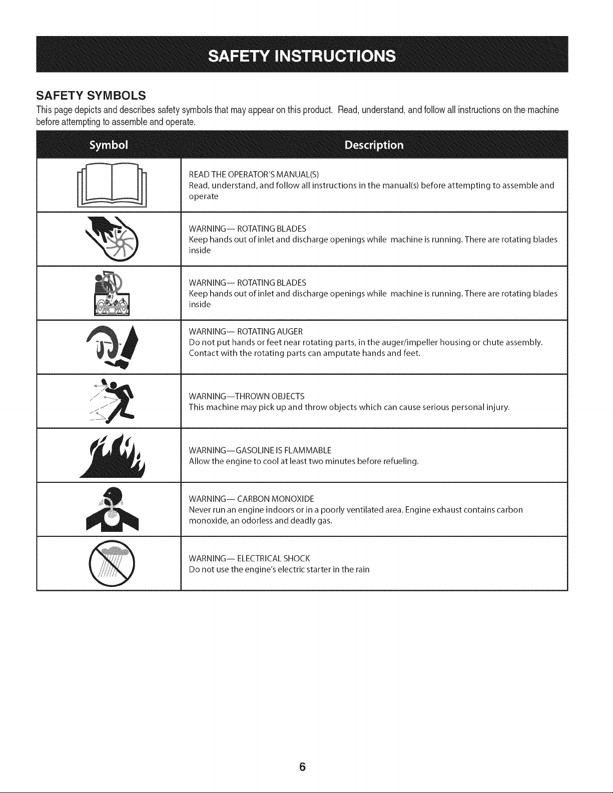
SAFETY SYMBOLS
Thispagedepictsand describessafetysymbolsthatmayappearonthisproduct. Read,understand,andfollowall instructionson the machine
beforeattemptingto assembleandoperate.
. +
i
i
"JIp
READ THE OPERATOR'S MANUAL(S)
Read, understand, and follow all instructions in the manual(s) before attempting to assemble and
operate
WARNING-- ROTATING BLADES
Keep hands out of inlet and discharge openings while machine is running. There are rotating blades
inside
WARNING-- ROTATING BLADES
Keep hands out of inlet and discharge openings while machine is running. There are rotating blades
inside
WARNING-- ROTATING AUGER
Do not put hands or feet near rotating parts, in the auger/impeller housing or chute assembly.
Contact with the rotating parts can amputate hands and feet.
WARNING--THROWN OBJECTS
This machine may pick up and throw objects which can cause serious personal injury.
WARNING--GASOLINE IS FLAMMABLE
Allow the engine to cool at least two minutes before refueling.
WARNING-- CARBON MONOXIDE
Never run an engine indoors or in a poorly ventilated area. Engine exhaust contains carbon
monoxide, an odorless and deadly gas+
WARNING-- ELECTRICAL SHOCK
Do not use the engine's electric starter in the rain
6
1. KEEPAWAYFROMROTATINGiMPELLERANDAUGER.CONTACT
WiTHiMPELLERORAUGERCANAMPUTATEHANDSANDFEET,
2, USECLEAN=OUTTOOLTOUNCLOGDISCHARGECHUTE.
3. DISENGAGECLUTCHLEVERS,STOPENGINE,ANDREMAINBEHIND
HANDLESUNTILALLMOVINGPARTSHAVESTOPPEDBEFORE
UNCLOGGINGORSERViCiNGMACHINE.
4. TOAVOIDTHROWNOBJECTSiNJURiES,NEVERDIRECT
DISCHARGEATBYSTANDERS.USEEXTRACAUTIONWHEN
OPERATINGONGRAVELSURFACES.
5. READOPERATOR'SMANUAL.
CLEAN-OUTTOOL =mll_li=J__
7
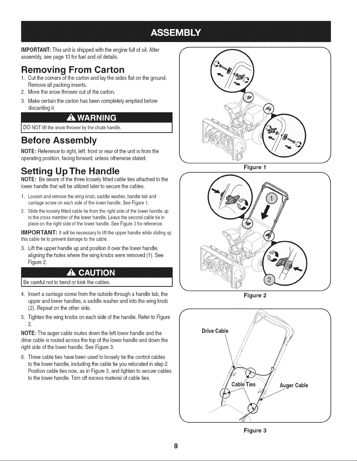
iMPORTANT:This unitis shippedwiththeengine fullof oil. After
assembly,see page 10for fuel andoildetails.
Removing From Carton
1. Cut the cornersof thecarton and lay the sidesflat on the ground.
Removeall packinginserts.
2. Movethe snowthrowerout of thecarton.
3. Makecertainthe cartonhas beencompletelyemptiedbefore
discardingit.
DO NOTliftthe snowthrower bythe chute handle.
Before Assembly
NOTE: Referenceto right,left, frontor rearof the unit isfromthe
operatingposition,facingforward,unlessotherwisestated.
Setting Up The Handle
NOTE: Be awareof the three looselyfitted cableties attachedto the
lowerhandlethat will be utilizedlaterto securethe cables.
1. Loosenand removethe wing knob,saddlewasher,handletab and
carriagescrew on eachside of the lowerhandle.See Figure1.
2. Slidethe looselyfitted cabletie from the rightside of the lowerhandle up
to thecross memberof the lowerhandle.Leavethe secondcabletie in
placeon the rightside of the lowerhandle.See Figure3 for reference.
iMPORTANT: Itwill be necessaryto lift the upper handlewhilesliding up
thiscable tie to preventdamage to thecable.
3. Lift the upper handle up and position it over the lower handle,
aligning the holes where the wing knobs were removed (1). See
Figure 2.
Becarefulnot to bendor kink the cables.
4. Inserta carriagescrewfromthe outsidethrougha handletab,the
upperand lowerhandles,a saddlewasherand intothe wing knob
(2). Repeatonthe otherside.
5. Tightenthewing knobson each sideof the handle.Referto Figure
2.
NOTE:The augercable routesdownthe left lowerhandleandthe
drivecableis routedacrossthe top of the lowerhandleanddownthe
rightside of the lowerhandle.SeeFigure3.
.
Threecabletieshavebeen usedto looselytie the controlcables
to the lowerhandle,includingthe cabletie you relocatedin step 2.
Positioncable tiesnow,as inFigure3, andtighten to securecables
to the lowerhandle.Trimoff excess materialof cableties.
f
Figure 1
Drive Cable
Figure 2
/
get Cable
_js jj
J
Figure 3
8
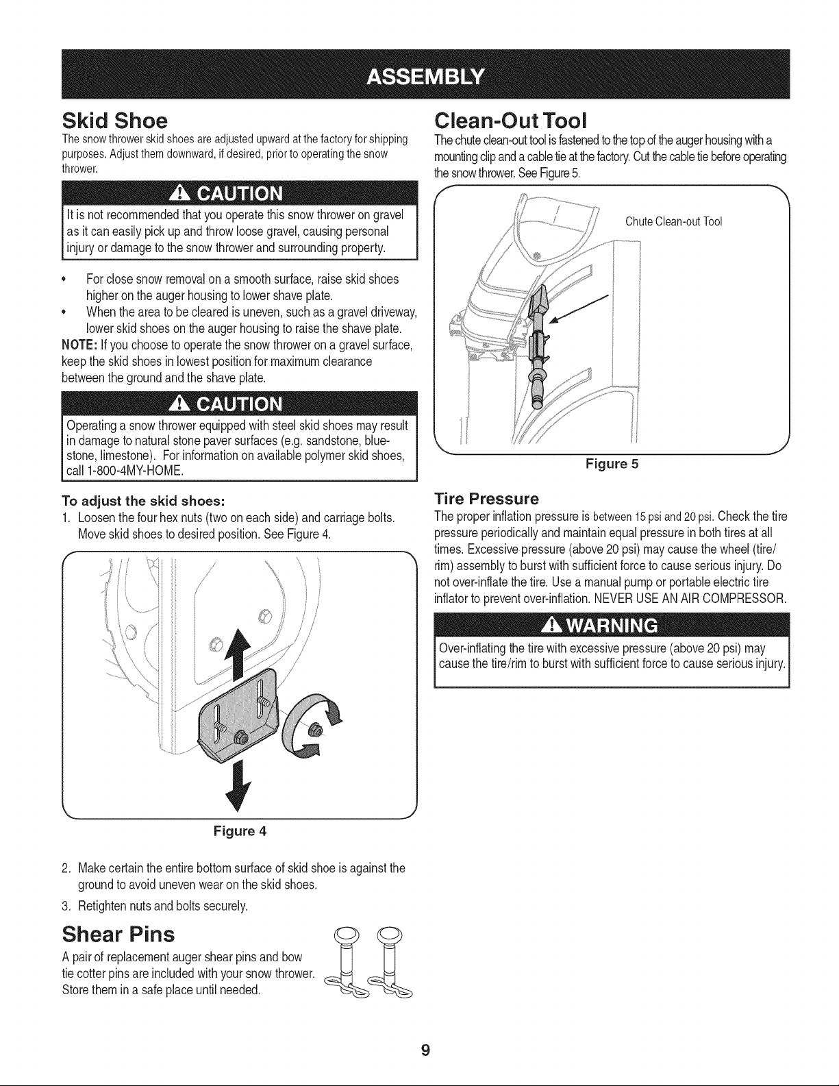
Skid Shoe
Thesnowthrowerskidshoesareadjustedupwardatthefactoryforshipping
purposes.Adjustthemdownward,ifdesired,priortooperatingthesnow
thrower.
It is not recommendedthatyouoperatethis snowthroweron gravel
as it can easilypick up andthrowloosegravel,causingpersonal
injuryor damageto the snowthrowerand surroundingproperty.
• Forclosesnowremovalon a smoothsurface,raiseskidshoes
higheronthe auger housingto lowershaveplate.
• Whenthearea to be clearedis uneven,suchas a graveldriveway,
lowerskid shoeson theaugerhousingto raisethe shaveplate.
NOTE: If you chooseto operatethe snowthroweron a gravelsurface,
keepthe skidshoesin lowestpositionfor maximumclearance
betweenthe groundandthe shaveplate.
Operatinga snowthrowerequippedwithsteelskidshoesmayresult
in damageto naturalstonepaversurfaces(e.g.sandstone,blue-
stone,limestone). Forinformationonavailablepolymerskid shoes,
call 1-800-4MY-HOME.
Clean-Out Tool
Thechuteclean-outtoolisfastenedto thetopd theaugerhousingwitha
mountingclipanda cabletieat thefactory.Cutthecabletiebeforeoperating
thesnowthrower.SeeFigure5.
ChuteClean-outTool
Figure 5
To adjust the skid shoes:
1. Loosenthe fourhex nuts(twooneach side)and carriagebolts.
Moveskidshoesto desiredposition.See Figure4.
/
/,
//
©
Tire Pressure
The properinflationpressureis between15psiand20psi.Checkthe tire
pressureperiodicallyand maintainequalpressurein bothtiresat all
times.Excessivepressure(above20 psi)maycausethe wheel(tire/
rim)assemblyto burstwithsufficientforceto causeseriousinjury.Do
notover-inflatethe tire. Use a manualpumpor portableelectrictire
inflatorto preventover-inflation.NEVERUSEANAIRCOMPRESSOR.
Over-inflatingthe tirewith excessivepressure(above20psi) may
causethe tire/rimto burstwithsufficientforceto causeseriousinjury.
Figure 4
2. Makecertain theentirebottomsurfaceof skid shoeis againstthe
groundto avoidunevenwearonthe skidshoes.
3. Retightennutsandboltssecurely.
Shear Pins
A pairof replacementaugershearpinsandbow
tie cotterpinsare includedwith yoursnowthrower.
Storethem in a safe placeuntilneeded.
9
Fuel Recommendations
Useautomotivegasoline(unleadedor low leadedto minimizecombus-
tionchamberdeposits)witha minimumof 87 octane.Gasolinewith
upto 10%ethanolor 15%MTBE(MethylTertiaryButyl Ether)canbe
used.Neverusean oil/gasolinemixtureor dirtygasoline.Avoidgetting
dirt,dust,or waterin thefuel tank. DO NOTuse E85gasoline.
* Refuelin awell-ventilatedareawiththe enginestopped.Donot
smokeor allowflamesorsparksin the area wheretheengine is
refueledor wheregasolineisstored.
* Do notoverfillthe fuel tank.After refueling,makesurethe tank
cap is closedproperlyandsecurely.
* Becarefulnot to spillfuel when refueling.Spilledfuelor fuelvapor
mayignite.Ifany fuel isspilled,makesurethe areaisdry before
startingtheengine.
* Avoidrepeatedor prolongedcontactwith skin or breathingof
vapor.
Adding Fuel
Useextremecarewhenhandlinggasoline.Gasolineis extremely
flammableand the vaporsare explosive. Neverfuel the machine
indoorsorwhile the engineishotor running.Extinguishcigarettes,
cigars,pipesandother sourcesof ignition.
Alwayskeephandsand feetclear of equipmentmovingparts.Do not
usea pressurizedstartingfluid.Vaporsare flammable.
1. Cleanaroundfuel fill beforeremovingcap to fuel.
2. A fuel levelindicatoris located inthefuel tank. Filltankuntil fuel
reachesthe fuel level indictor,Figure6. Be carefulnotto overfill.
FuelLevelIndicator
TopView
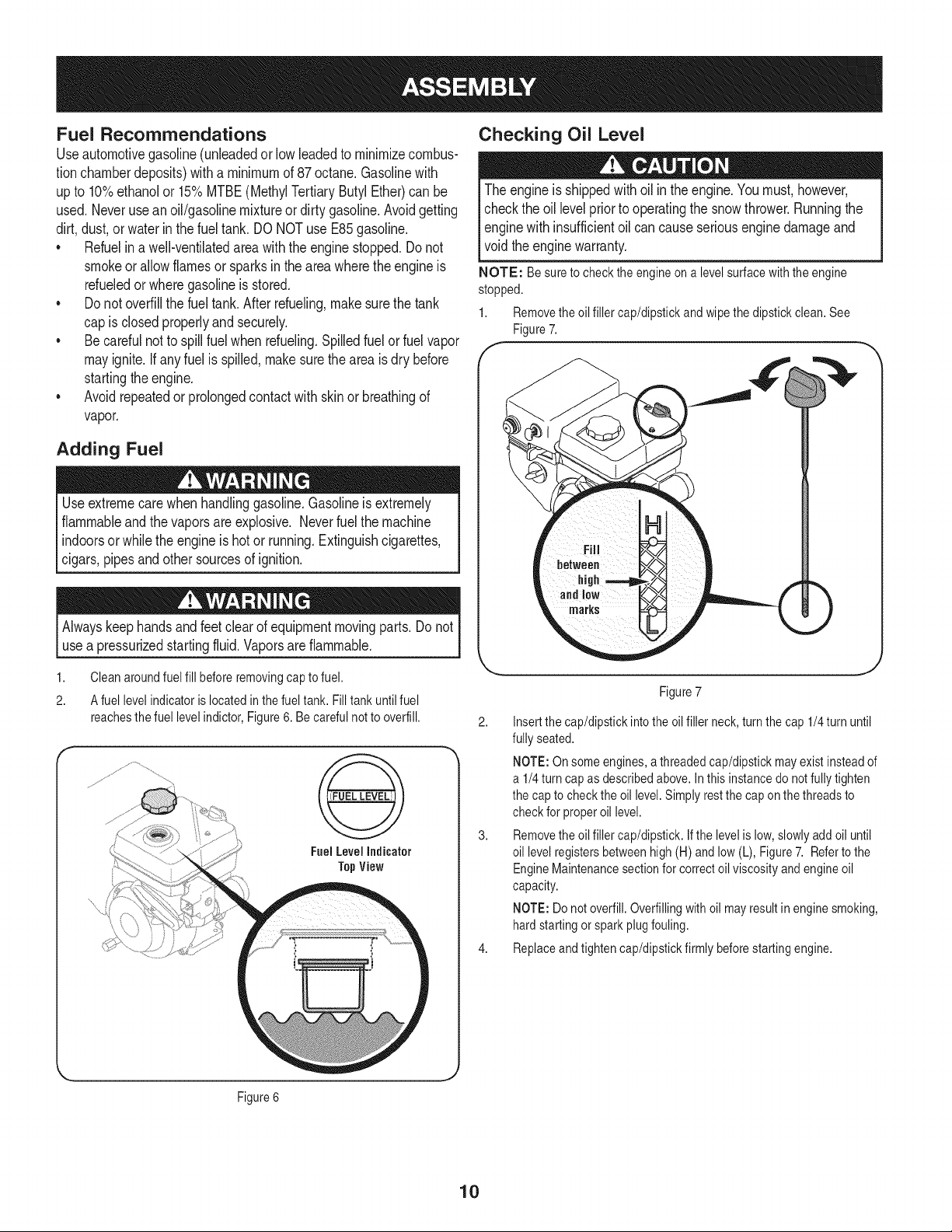
Checking Oil Level
The engineis shippedwithoil in theengine.Youmust, however,
checkthe oil levelpriorto operatingthe snowthrower.Runningthe
enginewithinsufficientoil cancauseseriousengine damageand
void theenginewarranty.
NOTE: Be sureto check the engineon a levelsurfacewith the engine
stopped.
1. Removetheoil filler cap/dipstickand wipethe dipstickclean.See
Figure7.
f-
)
Figure7
2. Insertthe cap/dipstickinto the oilfiller neck, turn thecap 1/4turn until
fully seated.
NOTE:On someengines,a threadedcap/dipstickmay existinsteadof
a 1/4turn cap as describedabove.In this instancedo notfully tighten
the cap to check the oil level.Simply restthe cap on the threadsto
check for properoil level.
3. Removethe oil filler cap/dipstick. Ifthe levelis low,slowlyadd oil until
oil levelregistersbetweenhigh (H) andlow (L), Figure7. Referto the
EngineMaintenancesectionfor correctoil viscosityandengine oil
capacity.
NOTE:Do notoverfill.Overfillingwith oil mayresult in enginesmoking,
hardstartingor sparkplugfouling.
4. Replaceandtighten cap/dipstickfirmly beforestartingengine.
Figure6
10
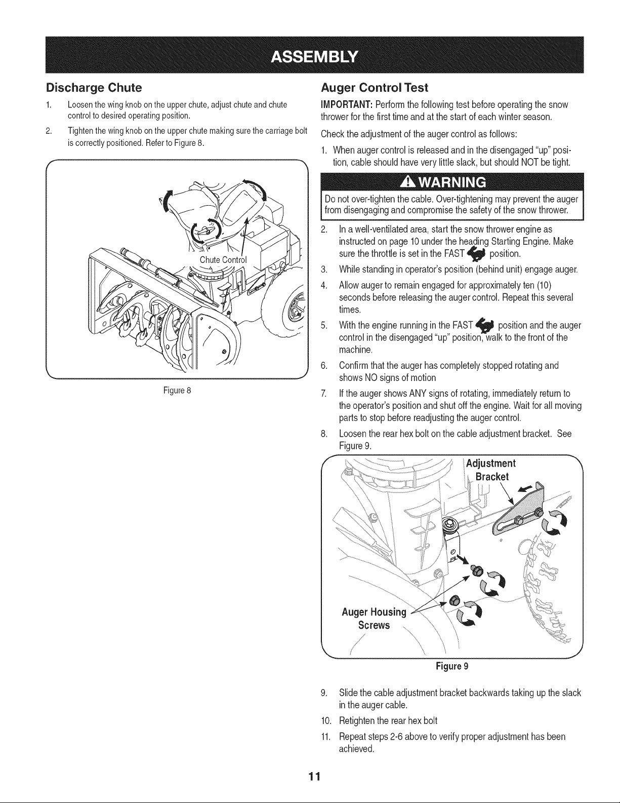
Discharge Chute
1. Loosenthewingknobontheupperchute,adjustchuteandchute
controlto desiredoperatingposition.
2. Tightenthewingknobontheupperchutemakingsurethecarriagebolt
iscorrectlypositioned.Referto Figure8.
Auger Control Test
iMPORTANT:Performthefollowingtest beforeoperatingthesnow
throwerfor the firsttimeandat the startof eachwinterseason.
Checkthe adjustmentof theaugercontrolas follows:
1. Whenaugercontrolisreleasedandinthe disengaged"up" posi-
tion,cable shouldhavevery littleslack,but shouldNOTbe tight.
Figure8
J
Donot over-tightenthe cable.Over-tighteningmaypreventthe auger
fromdisengagingand compromisethe safetyof the snowthrower.
2. Ina well-ventilatedarea,startthe snow throwerengineas
instructedon page10underthe headingStartingEngine.Make
thethrottleisset inthe FAST
sure
position.
3. Whilestandingin operator'sposition(behindunit) engageauger.
4. Allowaugerto remainengagedforapproximatelyten (10)
secondsbeforereleasingthe augercontrol.Repeatthis several
times.
5. Withthe engine runninginthe FAST_ positionand the
auger
controlinthe disengaged"up"position,walkto the frontof the
machine.
6. Confirmthatthe auger hascompletelystoppedrotatingand
showsNO signsof motion
7. Ifthe augershowsANYsignsof rotating,immediatelyreturnto
the operator'spositionand shut off the engine.Waitfor all moving
partsto stopbeforereadjustingthe augercontrol.
8. Loosenthe rear hexbolton the cableadjustmentbracket. See
Figure9.
f Adjustment "
Bracket
Auger Housing
Screws
Figure 9
9. Slidethe cableadjustmentbracketbackwardstakingup the slack
inthe augercable.
10. Retightenthe rearhexbolt
11. Repeatsteps2-6aboveto verifyproperadjustmenthas been
achieved.
11
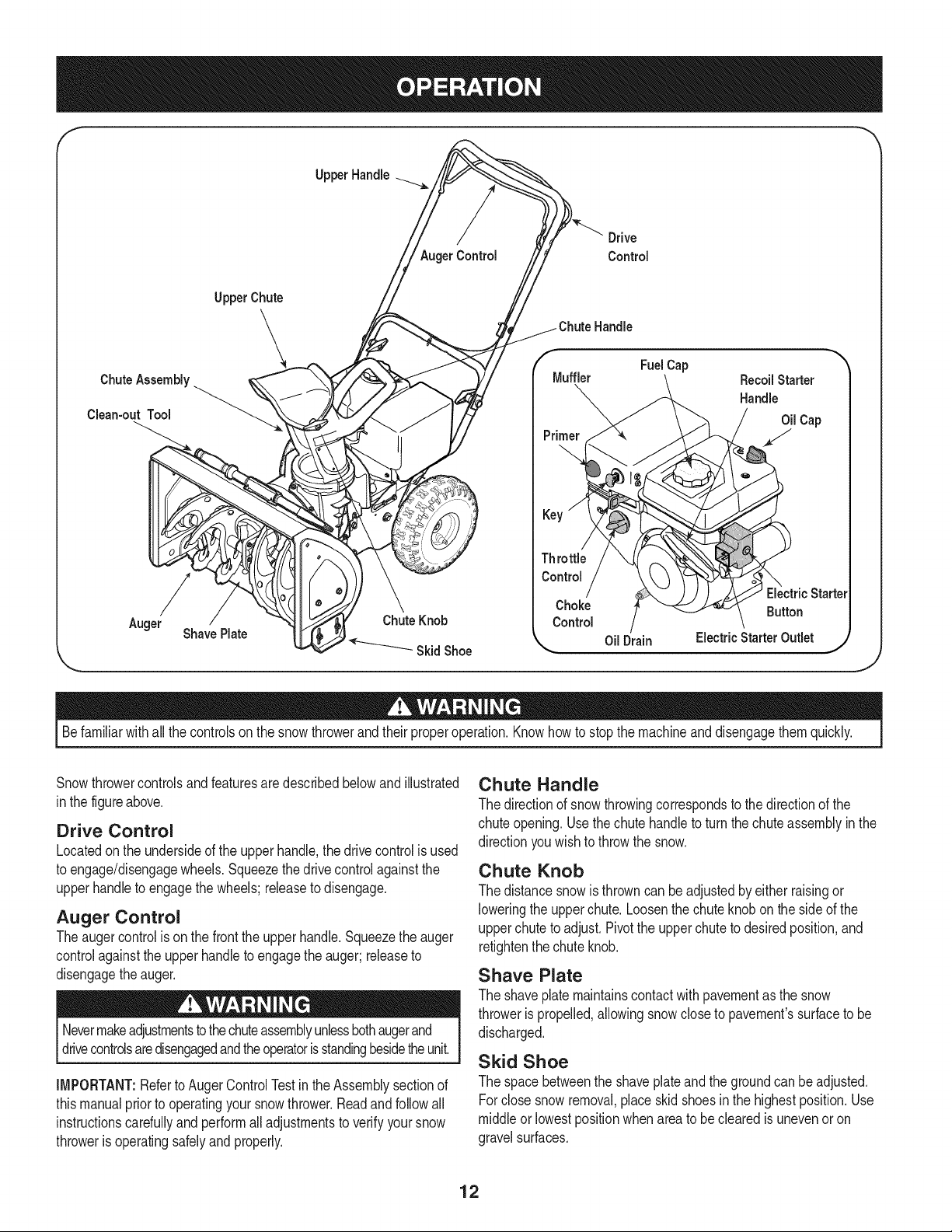
f
Upper Handle
Drive
AugerControl Control
Chute Assembly
Clean-out Tool
Auger
UpperChute
\
ShavePlate
Chute Knob
Skid Shoe
Handle
/f FuelCap
Muffler RecoilStarter
Handle
Oil Cap
Throttle
Control
ElectricStarter
Choke Button
Control
OilDrain ElectricStarterOutlet )
,J
Befamiliarwithall the controlson the snowthrowerand theirproperoperation.Knowhowto stopthe machineanddisengagethem quickly.
Snowthrowercontrolsandfeaturesare describedbelowandillustrated
inthe figureabove.
Drive Control
Locatedon the undersideof the upperhandle,the drivecontrolisused
to engage/disengagewheels.Squeezethe drivecontrolagainstthe
upperhandleto engagethe wheels;releaseto disengage.
Auger Control
Theauger controlis onthe frontthe upperhandle.Squeezethe auger
controlagainstthe upperhandleto engagethe auger;releaseto
disengagethe auger.
Nevermakeadjustmentstothechuteassemblyunlessbothaugerand
drivecontrolsaredisengagedandtheoperatorisstandingbesidetheunit.
IMPORTANT:Referto AugerControlTestinthe Assemblysectionof
thismanualprior to operatingyoursnow thrower.Readand followall
instructionscarefullyandperformall adjustmentsto verifyyoursnow
throweris operatingsafelyand properly.
Chute Handle
The directionof snowthrowingcorrespondsto thedirectionof the
chuteopening.Use thechutehandleto turn thechuteassemblyin the
directionyouwish to throwthe snow.
Chute Knob
The distancesnowis throwncan be adjustedby either raisingor
loweringthe upperchute.Loosenthe chute knobonthe side of the
upperchuteto adjust.Pivotthe upperchuteto desiredposition,and
retightenthechuteknob.
Shave Plate
The shaveplatemaintainscontactwithpavementas the snow
throweris propelled,allowingsnowclose to pavement'ssurfaceto be
discharged.
Skid Shoe
The spacebetweenthe shaveplateand thegroundcan be adjusted.
Forclose snowremoval,placeskid shoesin the highestposition.Use
middleor lowestpositionwhenarea to be clearedis unevenor on
gravelsurfaces.
12
Auger
Whenengaged,the auger rotatesanddrawssnowintothe auger
housing.
Chute Assembly
Snowdrawninto theaugerhousingis dischargedout the chute
assembly.
Choke Control
Thechokecontrol aidsin startingthe engine.For
informationon choke usage,seeStartingThe
Enginelaterin this section.
Recoil Starter & Starter Handle
Thismotoris fittedwitha recoilactionpullstartand
a mittengrip handlefor easyaccesswhilewearingglovesor mittens.
Key
Thekey is a safetydevice.It mustbefullyinserted _ ,,,,._
in orderfor the engineto start. Removethekey
Fe
whenthe snowthroweris not inuse.
NOTE:Do notturn the keyin anattemptto start
the engine.Doingso maycause it to break.
Electric Starter Button
Pressingthe electricstarterbuttonengagesthe engine'selectric
starterwhenpluggedintoa 120Vpowersource.
Clean=Out Tool
Neveruseyour handsto clear a cloggedchuteassembly.Shutoff
engineandremainbehindhandlesuntilall movingpartshavestopped
[before usng the c can-out too to c earthechute assemby.
The chuteclean-outtool is convenientlyfastenedto the rearof the
augerhousingwith a mountingclip.Shouldsnowand ice become
lodgedinthe chute assemblyduringoperation,proceedas followsto
safelycleanthe chuteassemblyandchuteopening:
1. Releaseboththe AugerControland the Drive Control.
2. Stoptheengineby removingthe key.
3. Removethe clean-outtool from the clipwhichsecuresit to the
rearof the auger housing.
4. Usethe shovel-shapedendof the clean-outtoolto dislodgeand
scoopanysnow and ice whichhas formedinand nearthe chute
assembly.
5. Refastenthe clean-outtoolto the mountingclip on the rearof
the auger housing,reinsertthe keyand startthe snowthrower's
engine.
6. Whilestandingin theoperator'sposition(behindthe snow
thrower),engagethe augercontrolfor a few secondsto clearany
remainingsnowand icefrom the chuteassembly.
Before Starting Engine
Electric Starter Outlet
Requiresthe useof a three-prongoutdoorextensioncord(included)
anda 120Vpowersource/walloutlet.
Primer
Pressingthe primerforcesfuel directlyinto
engine'scarburetorto aid in cold-weatherstarting, qk_/,..=_,,L.,_
Referto the startinginstructionsin theOperation I
sectionof this manualfor properprimerusage.The |
imagetothe rightcorrespondswiththe labelon the
engineidentifyingthe primer.
Oil Fill
Removeoil cap to addoil. Referto the Maintenance& Service section
for checkingandaddingoil instructions.
Gasoline Cap
Removegascap to add fuel. Unit runson regulargas.
NOTE:This unit may includea fuel plug,whichisonly usedduring
assemblyto keepdirt and debrisout of fueltank. Discardthefuel plug
beforefillingthe fuel tank.
Throttle Control
Read,understand,andfollowallinstructionsand warningsonthe
machineandinthis manualbeforeoperating.
Check Engine Oil
The unitwas shippedwith oil in the engine.Checkoil levelbeforeeach
operationto ensureadequateoil inthe engine.Forfurther instructions,
referto the Maintenance& Servicesectionof this manual.
NOTE:Be sureto checkthe engineona levelsurfacewith theengine
stopped.
1. Removethe oil filler cap/dipstickand wipe thedipstickclean.
2. Insertthe cap/dipstickintothe oil filler neck,turn thecap 1/4turn
untilfully seated.
NOTE:On someengines,a threadedcap/dipstickmayexist
insteadof a 1/4turncap as describedabove. Inthis instancedo
notfully tightenthe capto checktheoil level.Simplyrestthe cap
on the threadsto checkfor properoil level.
Removethe oil filler cap/dipstick.Ifthe levelis low,slowlyadd
oil (5W-30,witha minimumclassificationof SF/SG)untiloil level
registersbetweenhigh (H) and low (L).
NOTE:Donot overfill.Overfillingwithoil mayresultin enginesmoking,
hardstartingor sparkplug fouling.
4. Replaceandtightencap/dipstickfirmly beforestartingengine.
Thethrottlecontrolis locatedon the engine.It regulatesthe speedof
the engineand will shutoff the enginewhenplacedin the Stop__
position.
13
Gasoline
Useautomotivegasoline(unleadedor low leadedto minimizecombus-
tionchamberdeposits)witha minimumof 87 octane.Gasolinewith
upto 10%ethanolor 15%MTBE(MethylTertiaryButyl Ether)canbe
used.Neverusean oil/gasolinemixtureor dirtygasoline.Avoidgetting
dirt,dust,or waterin thefuel tank. DO NOTuse E85gasoline.
• Refuelin awell-ventilatedareawiththe engine stopped.Donot
smokeor allowflamesorsparksin the area wheretheengine is
refueledor wheregasolineisstored.
• Do notoverfillthe fuel tank.Afterrefueling,makesurethe tank
cap is closedproperlyandsecurely.
• Becarefulnot to spillfuel when refueling.Spilledfuelor fuelvapor
mayignite.Ifany fuel isspilled,makesurethe areaisdry before
startingtheengine.
• Avoidrepeatedor prolongedcontactwithskinor breathingof
vapor.
Useextremecarewhenhandlinggasoline.Gasolineis extremely
flammableand the vaporsareexplosive.Neverfuelthe machine
indoorsor whilethe engineishot or running.Extinguishcigarettes,
cigars,pipes andother sourcesof ignition.
1. Cleanaroundfuelfill beforeremovingcap to fuelto avoiddirt and
debrisfallingintofuel tank.
2. Afuel levelindicatorislocatedinthe fuel tank. Filltankuntilfuel
reachesthe fuel levelindictor.SeeFigure10 inset.Becarefulnot
to overfill.
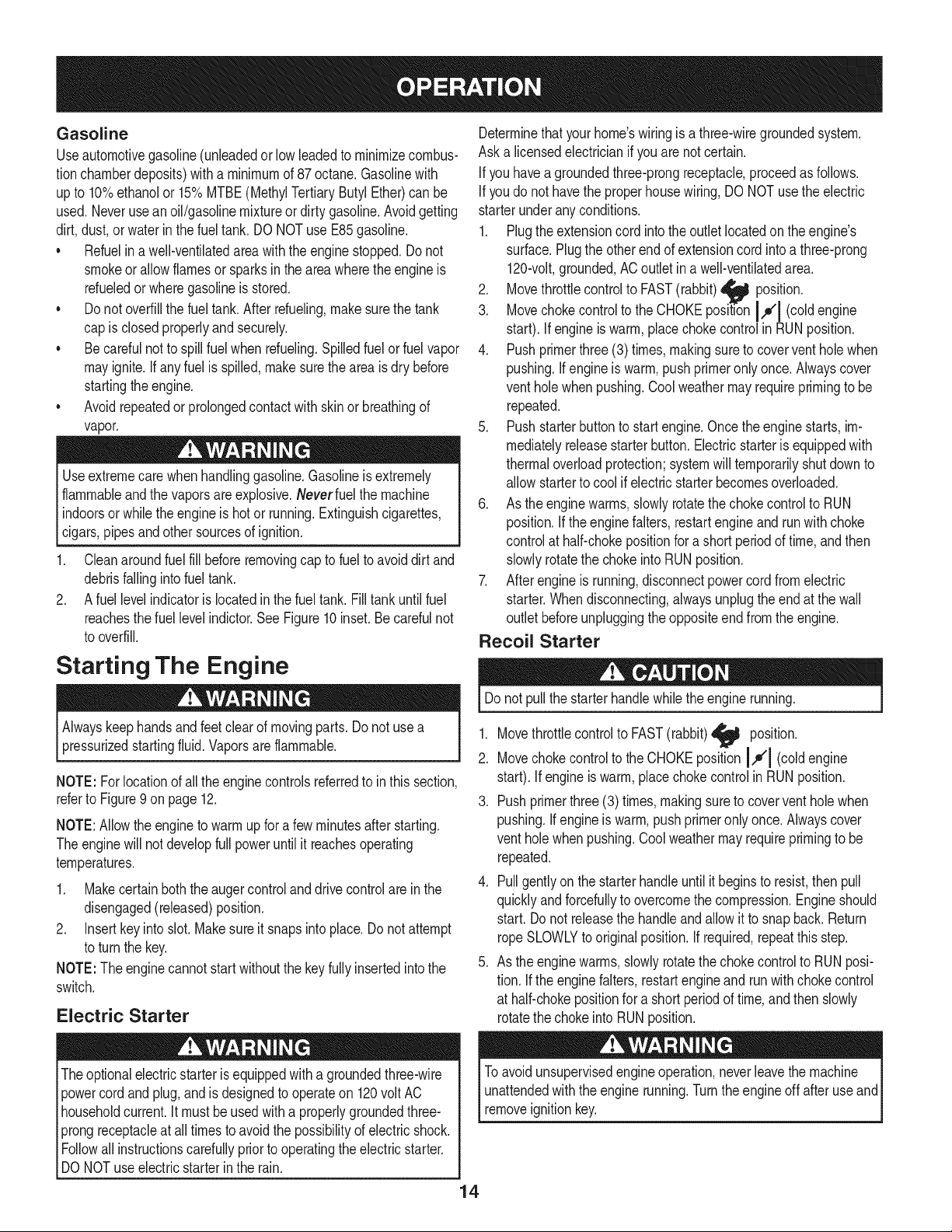
Starting The Engine
Alwayskeephandsand feetclear of movingparts.Do notuse a
pressurizedstartingfluid.Vaporsare flammable.
NOTE: Forlocationof allthe enginecontrolsreferredto inthis section,
referto Figure9on page12.
NOTE:Allowtheengineto warmup for a few minutesafterstarting.
Theenginewill not developfull poweruntil it reachesoperating
temperatures.
1. Makecertainboththe augercontrolanddrivecontrolare inthe
disengaged(released)position.
2. Insertkey into slot.Makesureit snapsinto place.Do notattempt
to turnthe key.
NOTE:The enginecannotstart withoutthe key fully insertedintothe
switch.
Electric Starter
Theoptionalelectricstarterisequippedwitha groundedthree-wire
powercord and plug,andisdesignedto operateon 120volt AC
householdcurrent.It mustbe usedwitha properlygroundedthree-
prongreceptacleat all timesto avoidthe possibilityof electricshock.
Followall instructionscarefullypriorto operatingthe electricstarter.
DO NOTuse electricstarterin the rain.
Determinethat yourhome'swiringis a three-wiregroundedsystem.
Aska licensedelectricianif you arenotcertain.
Ifyou havea groundedthree-prongreceptacle,proceedas follows.
Ifyou do not havethe properhousewiring, DONOTusethe electric
starterunder anyconditions.
1. Plugthe extensioncord intothe outlet locatedon the engine's
surface.Plugthe otherendof extensioncord intoa three-prong
120-volt,grounded,AC outletina well-ventilatedarea.
2. Movethrottlecontrolto FAST(rabbit)_ position.
3. Movechokecontrolto the CHOKEposition I,,o'1(coldengine
start). Ifengineiswarm,placechokecontrolinRUNposition.
4. Pushprimerthree(3) times,makingsureto coverventholewhen
pushing.If engineis warm,pushprimeronly once.Alwayscover
ventholewhenpushing.Coolweathermayrequireprimingto be
repeated.
5. Pushstarterbuttonto startengine.Oncetheenginestarts,im-
mediatelyreleasestarterbutton.Electricstarteris equippedwith
thermaloverloadprotection;systemwill temporarilyshutdownto
allow starterto cool if electricstarterbecomesoverloaded.
6. As the enginewarms,slowlyrotatethechoke controlto RUN
position.Ifthe enginefalters, restartengineand runwith choke
controlat half-chokepositionfor a short periodof time,andthen
slowlyrotatethe chokeintoRUNposition.
7. Afterengineis running,disconnectpowercord fromelectric
starter.Whendisconnecting,alwaysunplugthe end at the wall
outletbeforeunpluggingthe oppositeend fromthe engine.
Recoil Starter
Donot pullthe starterhandlewhiletheengine running.
1. Movethrottlecontrolto FAST(rabbit)_j_ position.
2. Movechokecontrolto the CHOKEpositionI,,_'l (coldengine
start). Ifengineiswarm,placechokecontrol in RUNposition.
3. Pushprimerthree(3) times,makingsureto coverventholewhen
pushing.If engineis warm,pushprimeronly once.Alwayscover
ventholewhenpushing.Coolweathermayrequireprimingto be
repeated.
4. Pullgently on the starterhandleuntil it beginsto resist,thenpull
quicklyand forcefullyto overcomethe compression.Engineshould
start. Donot releasethe handleandallowit to snapback.Return
ropeSLOWLYto originalposition.If required,repeatthis step.
5. As the enginewarms,slowlyrotatethechokecontrolto RUNposi-
tion. Ifthe enginefalters,restartengineandrunwithchokecontrol
at half-chokepositionfor a shortperiod of time,andthenslowly
rotatethe chokeintoRUNposition.
Toavoidunsupervisedengineoperation,neverleavethe machine
unattendedwiththe enginerunning.Turnthe engineoff afteruseand
removeignitionkey.
4
Stopping The Engine
Runenginefor a few minutesbeforestoppingto helpdry off any
moistureon the engine.
1. Movethrottlecontrolto STOP position.
2. Removethekey.Removingthe keywill reducethe possibilityof
unauthorizedstartingof the enginewhileequipmentis notin use.
Keepthe key in a safeplace.The enginecannotstart withoutthe
key.
3. Wipeany moistureawayfromthe controlson theengine..
To Stop The Snow Thrower
1. Tostopthe wheels,releasethe drivecontrol.
2. Tostopthrowingsnow,releasethe augercontrol.
3. Tostopengine,movethrottlecontrolleverto OFF @ and pull out
the key.Donot turn key.
Thetemperatureof mufflerand the surroundingareasmayexceed
1500F.Avoidtheseareas.
Using Snow Thrower to Clear
Snow
CAUTION:Checktheareato be clearedfor foreignobjects.Remove
foreignobjects,if any.
1. Start theenginefollowingstartinginstructions.
2. Allowtheengine to warmup for a few minutesas the enginewill not
developfull poweruntilit reachesoperatingtemperature.
3. Rotatethe chute assemblyto the desireddirection,awayfrom
bystandersand/or buildings.
4. Makingcertainno bystandersor obstaclesare in front of the unit,
squeezethe augercontrolcompletelyagainstthe upperhandleto
fullyengagetheauger.
5. Whiletheauger controlis engaged,squeezethe drivecontrol
completelyagainstthe upperhandleto engagethe wheels.Do not
"feather"thedrive control.
6. As the snowthrowerstartsto move,maintaina firmholdon the
handle,and guide the snowthroweralongthe pathto be cleared.
7. Releasethe augerand drivecontrolsto stopthe snowthrowing
actionandforwardmotion.
NOTE:Yourunit isequippedwitha clutchinthe transmission.If the
wheelsstopturningwhiletryingto dischargelargevolumesof snow,
immediatelydisengagethedrivecontroland allowthe rotatingauger
to dischargesnowfromthe housing.Reducethe clearingwidthand
continueoperation.
8. On eachsucceedingpass,readjustthe chuteassemblyto the
desiredpositionand slightlyoverlapthe previouslyclearedpath.
Positioning Discharge Chute
Loosenthechuteknoband pivotupperchuteto desiredposition.Tighten
the chuteknobmakingsurethe carriageboltiscorrectlypositioned.
Rotatechutehandleto desiredoperatingposition.
Donot lift the snowthrowerat any time bythe chute handle.
Operating Tips
1. Formostdficientsnowremoval,removesnowimmediatelyafteritfalls.
2. Dischargesnowdownwindwheneverpossible.Slightlyoverlap
each previouspath.
3. Setthe skidshoes1/4"belowthe shaveplatefor normalusage.
The skid shoesmay be adjustedupwardfor hard-packedsnow.
NOTE:It isnot recommendedthat youoperatethis snowthroweron
gravelas loosegravelcan be easilypickedup and thrownbythe auger
causingpersonalinjuryand/or damageto the snowthrower.
4. If you chooseto operatethe snowthrowerongravel,keepthe skid
shoeinthe lowestpositionfor maximumclearancebetweenthe
groundandthe shaveplate.
5. Cleanthe snowthrowerthoroughlyaftereachuse.
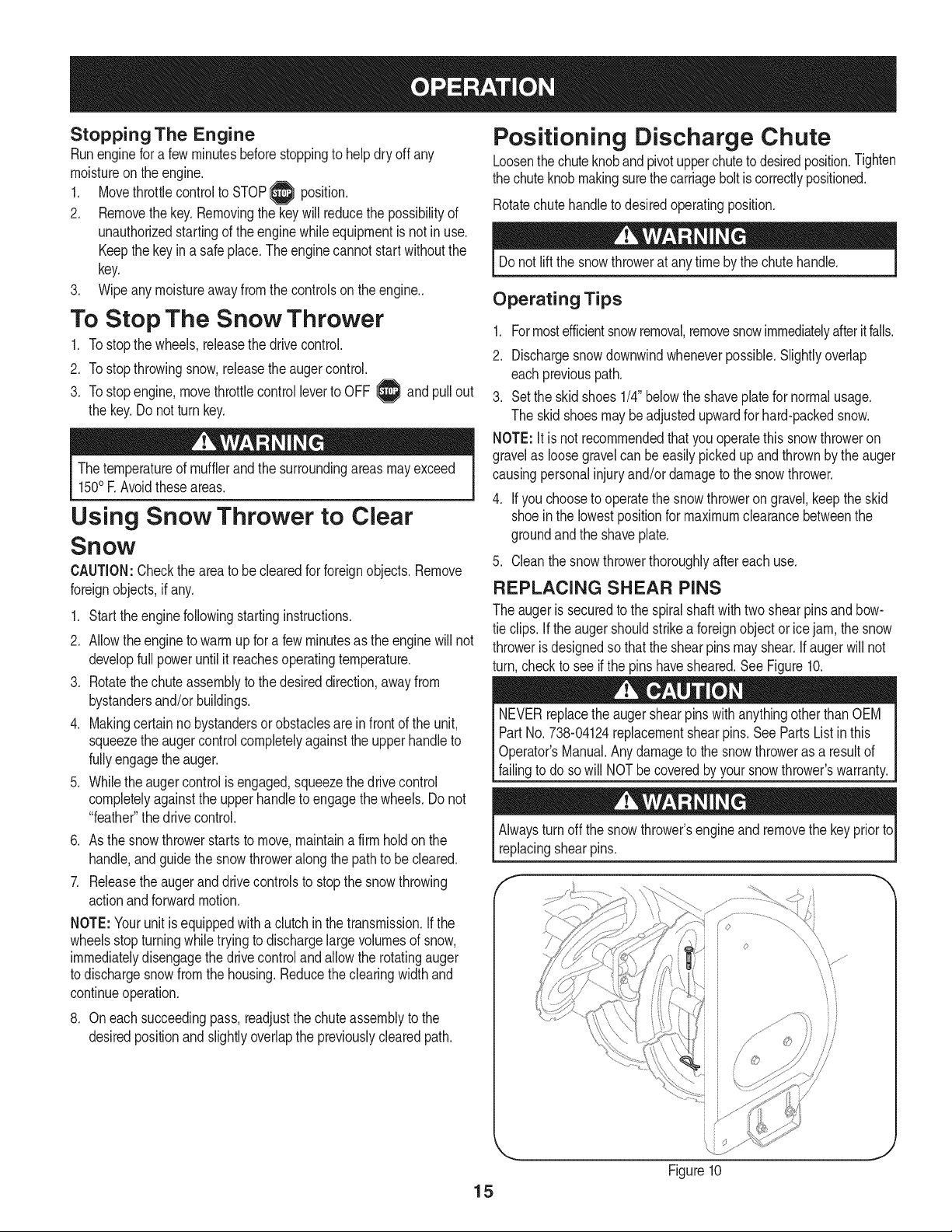
REPLACING SHEAR PINS
The augeris securedto the spiralshaftwithtwo shearpinsand bow-
tie clips. If the auger shouldstrikea foreignobjector icejam,the snow
throweris designedso thatthe shearpinsmay shear.Ifaugerwill not
turn,checkto see ifthe pins havesheared.SeeFigure10.
NEVERreplacethe augershearpinswith anythingotherthan OEM
PartNo. 738-04124replacementshearpins. See Parts List in this
Operator'sManual.Any damageto the snowthroweras a resultof
failingto do sowill NOTbecoveredbyyour snowthrower'swarranty.
Alwaysturn off the snowthrower'sengineand removethe keyprior to
replacingshearpins.
15
Figure10
J
Beforeservicing,repairing,lubricatingorinspecting,disengageall
controlsandstopengine.Waituntilallmovingpartshavecometoa
completestop.Removethekeytopreventunintendedstarting.Always
wearsafetyglassesduringoperationorwhileperforminganyadjust-
mentsorrepairs.
Followthemaintenanceschedulegivenbelow.Thischartdescribes
serviceguidelinesonly.UsetheServiceLogcolumntokeeptrack
ofcompletedmaintenancetasks.TolocatethenearestSears
ServiceCenteror to scheduleservice,simplycontact Searsat
1-800-4-MY-HOME®.
Maintenance Schedule
EachUseand every 5
hours
1st5 hours
Annuallyor 25hours
= =
1. Engineoil level
2. Looseor missinghardware
3. Unitandengine.
1. Engineoil
1. Sparkplug
2. Controllinkagesand pivots
3. Wheels
4. Gearshaft and Augershaft
1. Engineoil
1. Sparkplug
Annuallyor 50hours
Annuallyor 100hours
BeforeStorage 1. Fuelsystem 1.
1. Check
2. Tightenor replace
3. Clean
1. Change
1. Check
2. Lubewithlightoil
3. Lubewithmultipurposeautogrease
4. Lubewithlightoil
1. Change
1. Clean,adjustgap,or replaceif
necessary
Runengineuntilit stopsfrom lack
of fuel
f
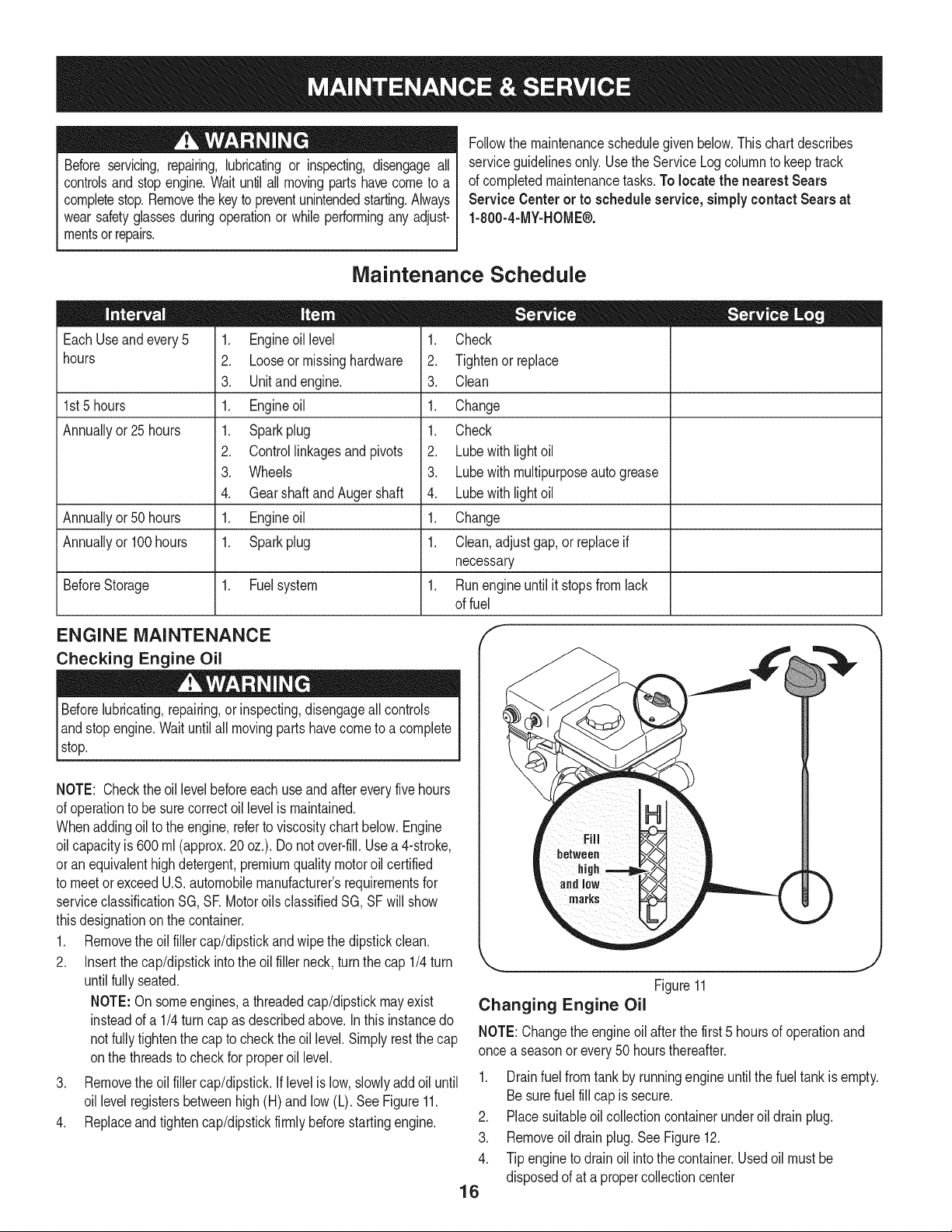
ENGINE MAINTENANCE
Checking Engine Oil
Beforelubricating,repairing,or inspecting,disengageall controls
Iand stop engine.Waituntilall movingpartshavecometo a complete
_stop.
NOTE: Checktheoil levelbeforeeachuseand after every five hours
of operationto besurecorrectoil levelis maintained.
Whenaddingoil to the engine,referto viscositychart below.Engine
oilcapacityis 600ml (approx.20 oz.). Donot over-fill.Usea 4-stroke,
oran equivalenthighdetergent,premiumquality motoroil certified
to meet or exceedU.S.automobilemanufacturer'srequirementsfor
serviceclassificationSG, SR MotoroilsclassifiedSG, SFwill show
thisdesignationonthe container.
1. Removethe oil fillercap/dipstickandwipethe dipstickclean.
2. Insertthe cap/dipstickintothe oil filler neck,turnthe cap 1/4turn
untilfully seated.
NOTE:On someengines,a threadedcap/dipstickmayexist
insteadof a 1/4turn cap as describedabove.In thisinstancedo
not fullytightenthe cap to checkthe oil level.Simplyrestthe cap
onthe threadsto checkfor properoil level.
3. Removethe oil fillercap/dipstick.Iflevelis low,slowlyadd oiluntil
oil levelregistersbetweenhigh(H) and low (L). SeeFigure11.
4. Replaceandtightencap/dipstickfirmlybeforestartingengine.
j
Figure11
Changing Engine Oil
NOTE:Changethe engineoil after thefirst 5 hoursof operationand
once a seasonor every50 hoursthereafter.
1. Drainfuel from tank by runningengine untilthefuel tank is empty.
Besurefuel fill capis secure.
2. Placesuitableoil collectioncontainerunderoil drainplug.
3. Removeoil drainplug.SeeFigure12.
4. Tip engineto drain oil intothe container.Usedoil mustbe
disposedof at a propercollectioncenter
16
f
Usedoil is a hazardouswasteproduct.Disposeof usedoil properly.
Donotdiscardwith householdwaste.Checkwith yourlocalauthori-
tiesor SearsServiceCenterfor safedisposal/recyclingfacilities.
.
6.
Reinstallthe drain plugand tightenit securely.
Refillwiththe recommendedoil and checkthe oil level.See
RecommendedOil Usagechart.Theengine'soil capacityis 20
ounces.
i i
(%-400 -200 0o 200 400
("c) -30° -20° -10° 0°
Oil Drain
Plug
Figure12
.J
DO NOTuse non-detergentoil or 2-strokeengineoil. It could shorten
the engine'sservicelife.
7. Reinstallthe oil fillercap/dipsticksecurely.
Thoroughlywashyour handswith soapandwateras soonas
possibleafterhandling usedoil.
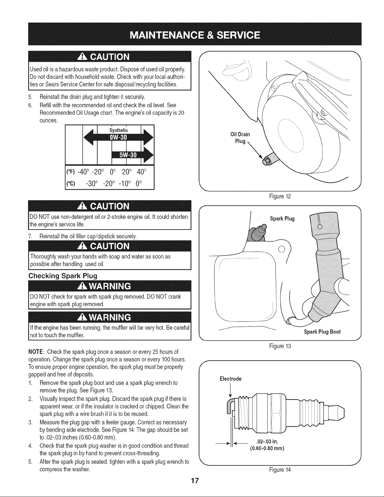
Checking Spark Plug
DO NOTcheckfor sparkwithsparkplugremoved.DO NOTcrank
enginewithsparkplugremoved.
Ifthe engine hasbeenrunning,the mufflerwill bevery hot.Becareful
notto touchthe muffler.
NOTE: Checkthe sparkplugoncea seasonorevery25hoursof
operation.Changethe sparkplug oncea seasonor every100hours.
Toensureproperengine operation,the sparkplug mustbe properly
gappedandfreeof deposits.
1. Removethespark plug bootanduse a sparkplugwrenchto
removethe plug.See Figure13.
2. Visuallyinspectthe spark plug.Discardthe spark plug if thereis
apparentwear,or if the insulatoris crackedor chipped.Cleanthe
sparkplugwitha wirebrush if it is to be reused.
3. Measurethe pluggapwitha feelergauge.Correctas necessary
by bendingsideelectrode.SeeFigure14.The gap shouldbeset
to .02-.03inches(0.60-0.80ram).
4. Checkthatthe sparkplug washeris ingoodconditionandthread
the sparkplug in by handto preventcross-threading.
5. Afterthespark plug is seated,tightenwitha sparkplugwrenchto
compressthe washer.
SparkPlug
Spark Plug Boot
Figure13
Electrode
___,. ,___ .02-.03 in.
(0.60-0.80 ram)
Figure14
17
NOTE:Wheninstallinga newsparkplug,tighten 1/2-turnafterthe
sparkplugseatsto compressthe washer.Whenreinstallinga used
sparkplug,tighten 1/81to 1/41turnafterthe sparkplugseatsto
compressthe washer.GeneralRecommendations
1. Alwaysobservesafetyruleswhenperformingany maintenance.
2. Thewarrantyon thissnowthrowerdoes notcoveritemsthat have
beensubjectedto operatorabuseor negligence.To receivefull
valuefromthe warranty,operatormustmaintainthe snowthrower
as instructedin thismanual.
3. Periodicallycheckall fastenersand hardwareto makesurethese
aretight.
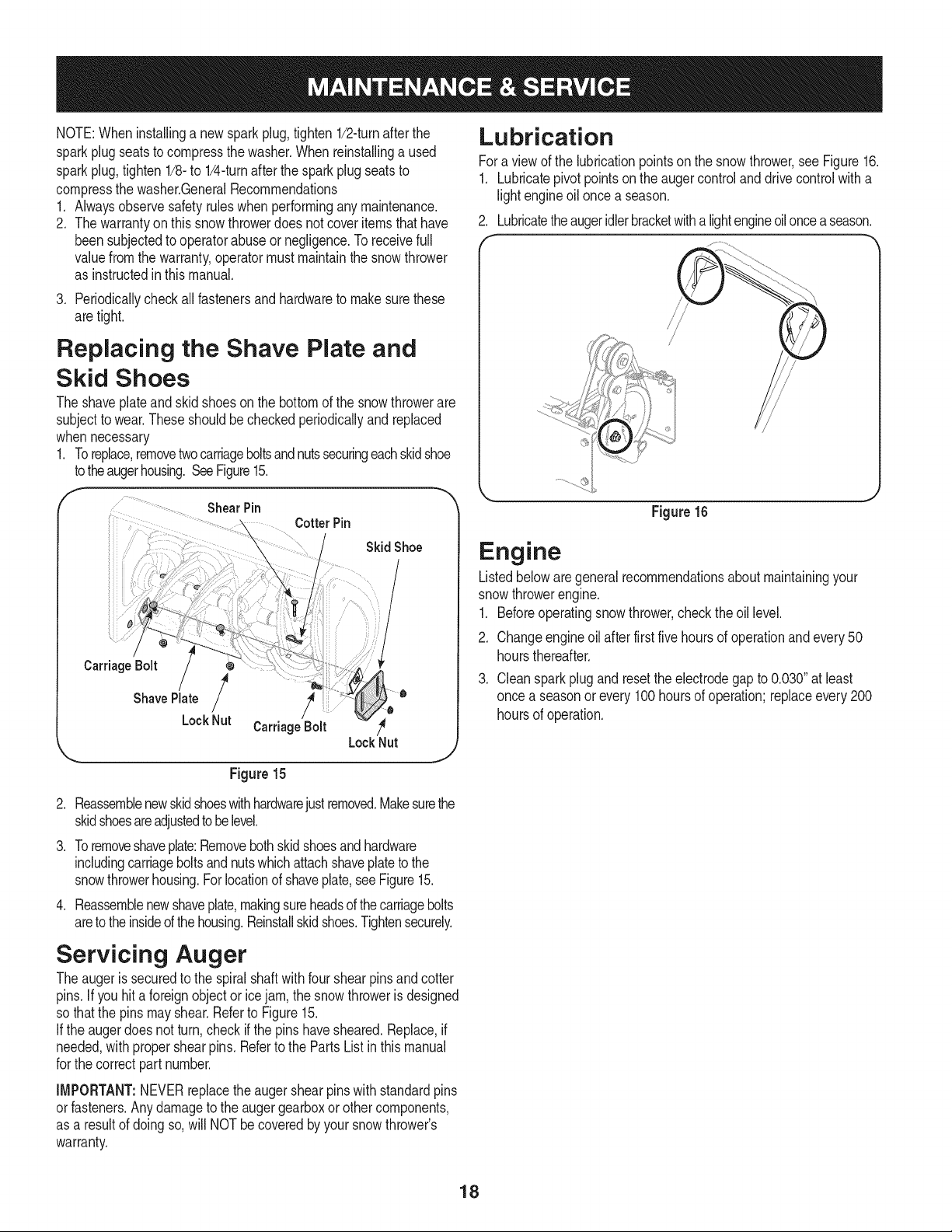
Replacing the Shave Plate and
Skid Shoes
The shaveplateand skid shoesonthe bottomof the snowthrowerare
subjectto wear.These shouldbe checkedperiodicallyandreplaced
whennecessary
1. Toreplace,removetwocarriageboltsandnutssecuringeachskidshoe
totheaugerhousing.SeeFigure15.
f
ShearPin
CotterPin
Carriage Bolt
Shave Plate /
LockNut
SkidShoe
l
/
CarriageBolt /_
LockNut
Figure15
J
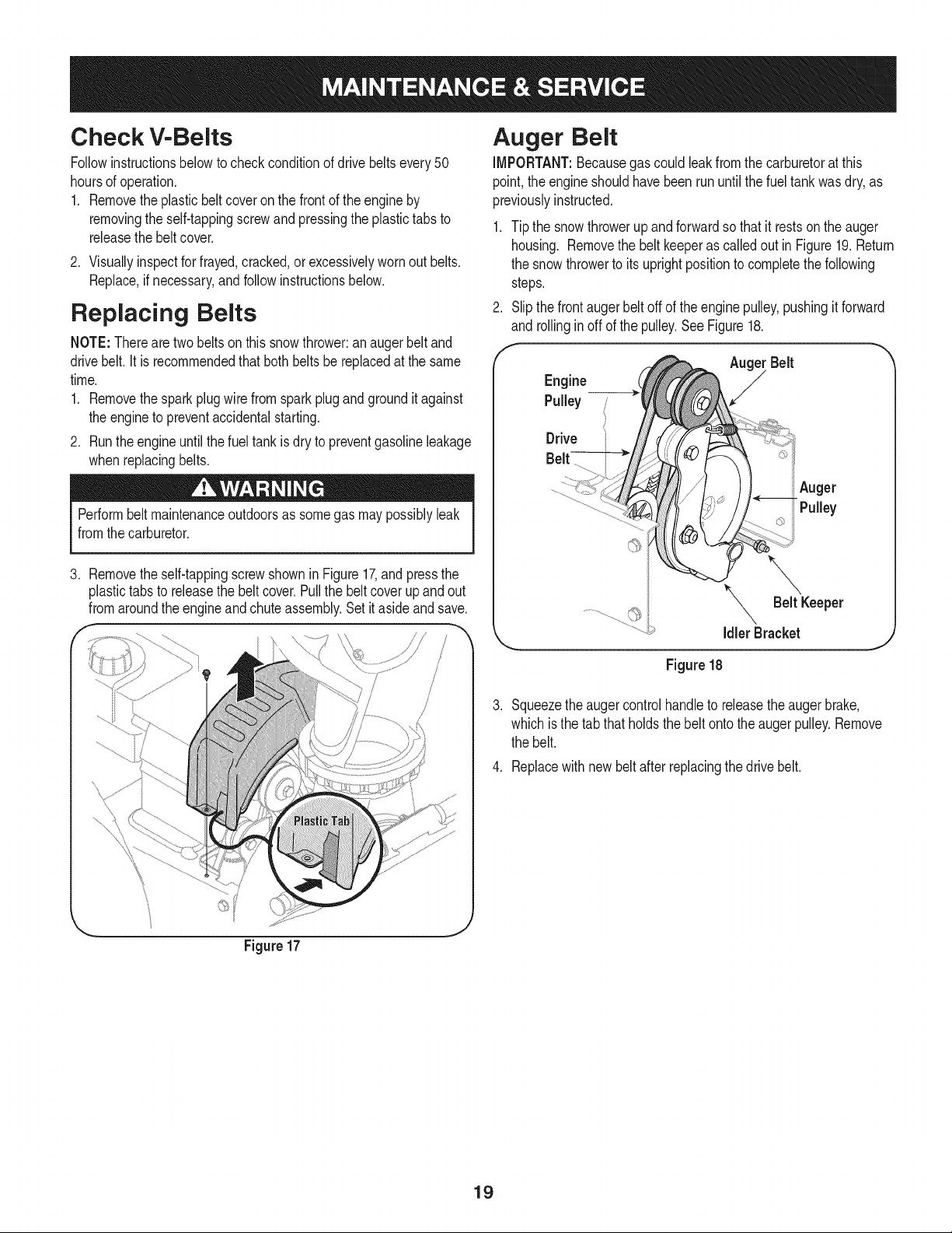
Lubrication
Fora viewof the lubricationpointsonthe snowthrower,see Figure16.
1. Lubricatepivotpointson the augercontroland drivecontrolwitha
light engineoil once a season.
2. Lubricatetheaugeridlerbracketwitha lightengineoilonceaseason.
Figure 16
Engine
Listedbeloware general recommendationsaboutmaintainingyour
snowthrowerengine.
1. Beforeoperatingsnowthrower,checkthe oil level.
2. Changeengineoilafterfirst five hoursof operationand every 50
hoursthereafter.
3. Cleansparkplugandresetthe electrodegapto 0.030"at least
once a seasonor every 100hoursof operation;replaceevery200
hoursof operation.
.
3.
.
Reassemblenewskidshoeswithhardwarejustremoved.Makesurethe
skidshoesareadjustedtobe level.
Toremoveshaveplate:Removebothskid shoesand hardware
includingcarriageboltsand nutswhichattachshaveplatetothe
snowthrowerhousing.Forlocationof shaveplate,see Figure15.
Reassemblenewshaveplate,makingsureheadsof thecarriagebolts
areto theinsideof thehousing.Reinstallskidshoes.Tightensecurely.
Servicing Auger
Theauger is securedto the spiralshaftwith fourshearpinsand cotter
pins.Ifyou hit a foreignobject or ice jam,the snowthroweris designed
so that the pinsmayshear.Referto Figure15.
Ifthe auger doesnot turn,check ifthe pinshavesheared.Replace,if
needed,with propershearpins.Referto the Parts List inthis manual
for thecorrectpart number.
IMPORTANT:NEVERreplacetheauger shearpinswith standardpins
orfasteners.Anydamageto the auger gearboxor othercomponents,
as a resultof doing so, will NOTbe coveredby yoursnowthrower's
warranty.
18
Check V-Belts
Followinstructionsbelowto checkconditionof drivebeltsevery50
hoursof operation.
1. Removetheplasticbelt coveronthe front of the engineby
removingthe self-tappingscrewand pressingthe plastictabs to
releasethe beltcover.
2. Visuallyinspectfor frayed,cracked,orexcessivelyworn outbelts.
Replace,if necessary,andfollowinstructionsbelow.
Replacing Belts
NOTE:Therearetwobeltson this snowthrower:an augerbelt and
drivebelt. It isrecommendedthat both belts be replacedat the same
time.
1. Removethespark plug wirefromsparkplugandgrounditagainst
the engineto preventaccidentalstarting.
2. Runthe engineuntilthe fuel tankisdry to preventgasolineleakage
whenreplacingbelts.
Performbelt maintenanceoutdoorsas somegas maypossiblyleak
fromthe carburetor.
3. Removetheself-tappingscrewshownin Figure17,andpressthe
plastictabs to releasethe beltcover.Pullthe belt coverupand out
fromaroundthe engineandchuteassembly.Set it asideandsave.
Figure17
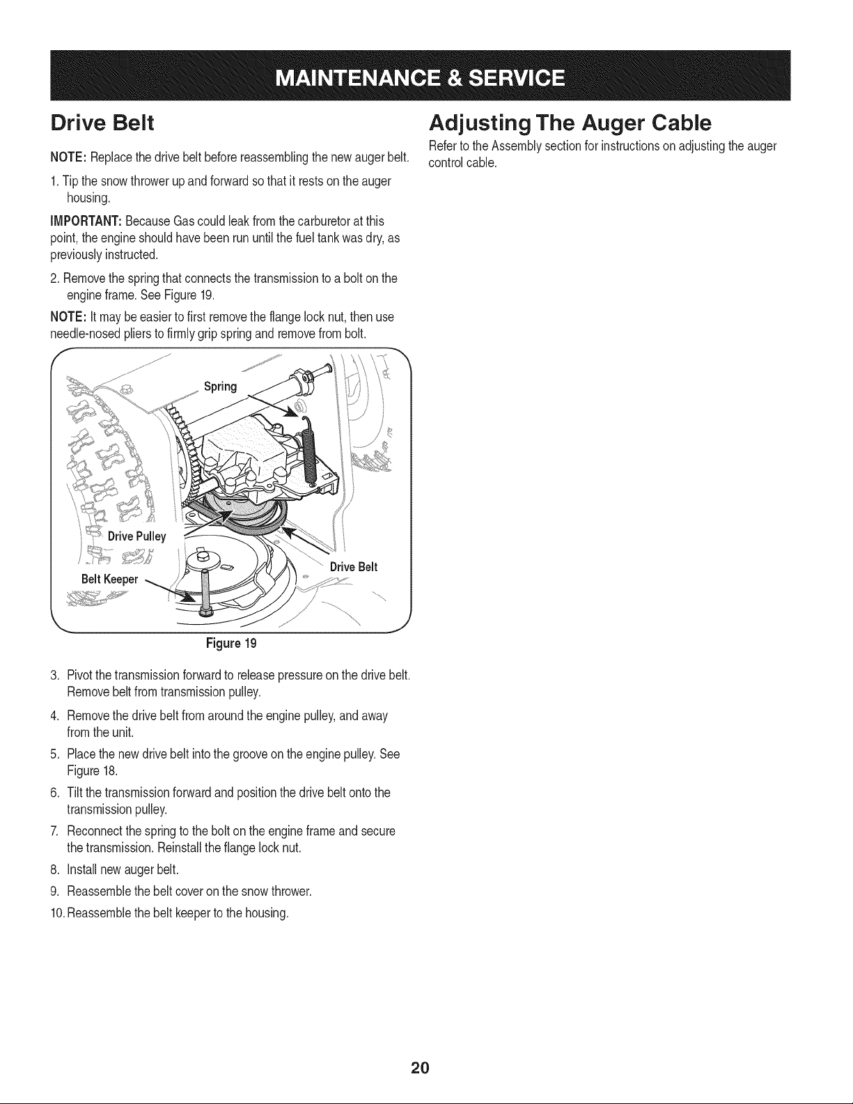
Auger Belt
iMPORTANT:Becausegas could leakfromthe carburetorat this
point,the engineshouldhavebeen run until thefuel tankwasdry,as
previouslyinstructed.
1. Tip the snowthrowerupandforwardso that it restson the auger
housing. Removethe beltkeeperas calledout inFigure19.Return
the snow throwerto itsuprightpositionto completethe following
steps.
2. Slipthe frontaugerbelt offof theengine pulley,pushingit forward
and rollinginoff of the pulley.SeeFigure18.
Idler Bracket
Figure18
Squeezethe augercontrolhandleto releasetheaugerbrake,
whichisthe tab thatholdsthe beltonto theauger pulley.Remove
the belt.
4. Replacewithnew beltafterreplacingthedrive belt.
19
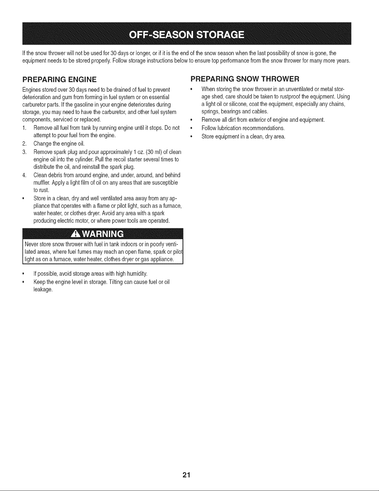
Drive Belt
NOTE: Replacethe drivebelt beforereassemblingthe newaugerbelt.
1.Tip the snowthrowerupandforwardsothat it restson theauger
housing.
IMPORTANT:BecauseGascould leakfromthecarburetorat this
point,the engineshouldhavebeen run untilthe fuel tankwas dry, as
previouslyinstructed.
2. Removethe springthat connectsthe transmissionto a bolt on the
engineframe.See Figure19.
NOTE: It may be easierto first removethe flangelock nut, then use
needle-nosedpliersto firmlygrip springandremovefrom bolt.
F
Adjusting The Auger Cable
Referto theAssemblysectionfor instructionson adjustingthe auger
controlcable.
Spring
........ _'*'_:" ...............DriveBelt
BeltKeeper
Figure19
3. Pivotthe transmissionforwardto releasepressureon the drivebelt.
Removebeltfromtransmissionpulley.
4. Removethe drivebelt from aroundthe enginepulley,and away
fromthe unit.
5. Placethe newdrivebelt intothe grooveonthe enginepulley.See
Figure18.
6. Tilt the transmissionforwardandpositionthe drive beltontothe
transmissionpulley.
7. Reconnectthe springto thebolt onthe engineframeandsecure
thetransmission.Reinstalltheflange lock nut.
8. Installnewauger belt.
9. Reassemblethe belt coveronthe snowthrower.
10.Reassemblethe belt keeperto the housing.
2O
Ifthe snowthrowerwillnot be usedfor30 daysor longer,or if it is the end of the snowseasonwhenthe last possibilityof snowis gone,the
equipmentneedsto be storedproperly.Followstorageinstructionsbelowto ensuretop performancefromthe snowthrowerfor manymoreyears.
PREPARING ENGINE
Enginesstoredover30daysneedto be drainedof fuel to prevent
deteriorationandgumfrom formingin fuel systemor onessential
carburetorparts.If thegasolineinyourenginedeterioratesduring
storage,youmayneedto havethe carburetor,andotherfuel system
components,servicedor replaced.
1. Removeall fuel fromtank by runningengineuntil it stops.Donot
attemptto pourfuel from the engine.
2. Changethe engineoil.
3. Removesparkplug and pour approximately1 oz. (30 rnl)of clean
engineoil intothe cylinder.Pullthe recoilstarterseveraltimesto
distributetheoil, and reinstallthe spark plug.
4. Cleandebrisfromaroundengine,and under,around,and behind
muffler.Applya lightfilm of oil on anyareasthatare susceptible
to rust.
• Storeina clean,dry andwellventilatedarea awayfrom anyap-
pliancethat operateswith a flame or pilotlight,suchas a furnace,
waterheater,or clothesdryer.Avoidany areawith a spark
producingelectricmotor,or wherepowertoolsareoperated.
Neverstoresnowthrowerwithfuel intank indoorsor inpoorlyventi-
latedareas,wherefuel fumesmayreachan openflame,spark or pilol
lightas ona furnace,waterheater,clothesdryer or gas appliance.
• If possible,avoidstorageareaswithhighhumidity.
• Keepthe enginelevelin storage.Tiltingcan causefuel oroil
leakage.
PREPARING SNOW THROWER
Whenstoringthe snowthrowerin an unventilatedormetalstor-
age shed,careshouldbetakento rustprooftheequipment.Using
a light oilor silicone,coattheequipment,especiallyanychains,
springs,bearingsandcables.
• Removealldirt fromexteriorof engineandequipment.
• Followlubricationrecommendations.
• Storeequipmentin a clean,dry area.
21
Beforeperforminganytypeof maintenance/service,disengageall
controlsandstopthe engine.Waituntilallmovingpartshavecometo a
completestop.Removethekeyto preventunintendedstarting.Always
wearsafetyglassesduringoperationorwhileperforminganyadjustments
orrepairs.
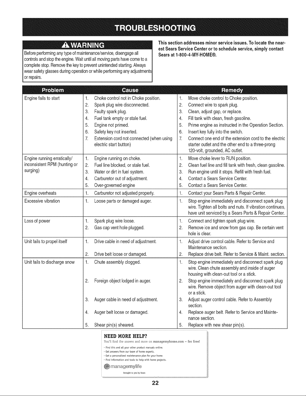
This sectionaddresses minor serviceissues.To locate the near-
est Sears Service Centerorto scheduleservice,simplycontact
Searsat 1-800-4-MY-HOME®.
Enginefailsto start
Enginerunningerratically/
inconsistentRPM(huntingor
surging)
1. Chokecontrolnot in Chokeposition.
2. Sparkplug wiredisconnected.
3. Faultysparkplug.
4. Fueltank emptyor stalefuel.
5. Enginenot primed.
6. Safetykey not inserted.
7. Extensioncord notconnected(whenusing
electricstart button)
.
2.
3.
4.
5.
1.
1.
Engineoverheats
Excessivevibration
Lossof power 1. Sparkplugwireloose.
2. Gascap ventholeplugged.
Unitfailsto propelitself 1. Drivecablein needof adjustment.
2. Drivebeltlooseordamaged.
Unitfailsto dischargesnow 1. Chuteassemblyclogged.
2. Foreignobject lodgedin auger.
1. Movechokecontrolto Chokeposition.
2. Connectwireto sparkplug.
3. Clean,adjustgap, or replace.
4. Filltank with clean,fresh gasoline.
5. Primeengineas instructedin theOperationSection.
6. Insertkey fully intothe switch.
7. Connectone end of the extensioncordto the electric
starteroutletand the otherend to a three-prong
120-volt,grounded,AC outlet.
Enginerunningonchoke. 1. Movechokeleverto RUNposition.
Fuelline blocked,or stalefuel. 2. Cleanfuel lineandfill tankwithfresh, cleangasoline.
Wateror dirt infuel system. 3. Runengine untilit stops.Refillwithfreshfuel.
Carburetoroutof adjustment. 4. Contacta SearsServiceCenter.
Over-governedengine 5. Contacta SearsServiceCenter.
Carburetornotadjustedproperly. 1. ContactyourSearsParts & RepairCenter.
Looseparts or damagedauger. 1. Stopengineimmediatelyanddisconnectspark plug
wire.Tightenall boltsandnuts.If vibrationcontinues,
haveunit servicedby a SearsParts& RepairCenter.
1. Connectandtightensparkplugwire.
2. Removeice and snowfrom gas cap.Becertainvent
holeis clear.
1. Adjustdrivecontrolcable.Referto Serviceand
Maintenancesection.
2. Replacedrivebelt.Referto Service & Maint.section.
1. Stopengineimmediatelyanddisconnectspark plug
wire.Cleanchute assemblyandinsideof auger
housingwith clean-outtoolor a stick.
2. Stopengine immediatelyand disconnectspark plug
wire.Removeobject from augerwith clean-outtool
or a stick.
Augercable in need of adjustment. 3. Adjustaugercontrolcable.Referto Assembly
section.
Augerbeltlooseor damaged. 4. Replaceaugerbelt.Referto Serviceand Mainte-
nancesection.
Shearpin(s)sheared. 5. Replacewith newshearpin(s).
NEED MORE HELP?
o Find this and a[[ your other product manuals online.
o 6et answers from our team of home experts.
o 6et a personalized maintenance plan for your home,
o Find information and tools to help with home projects.
.
4.
5.
22
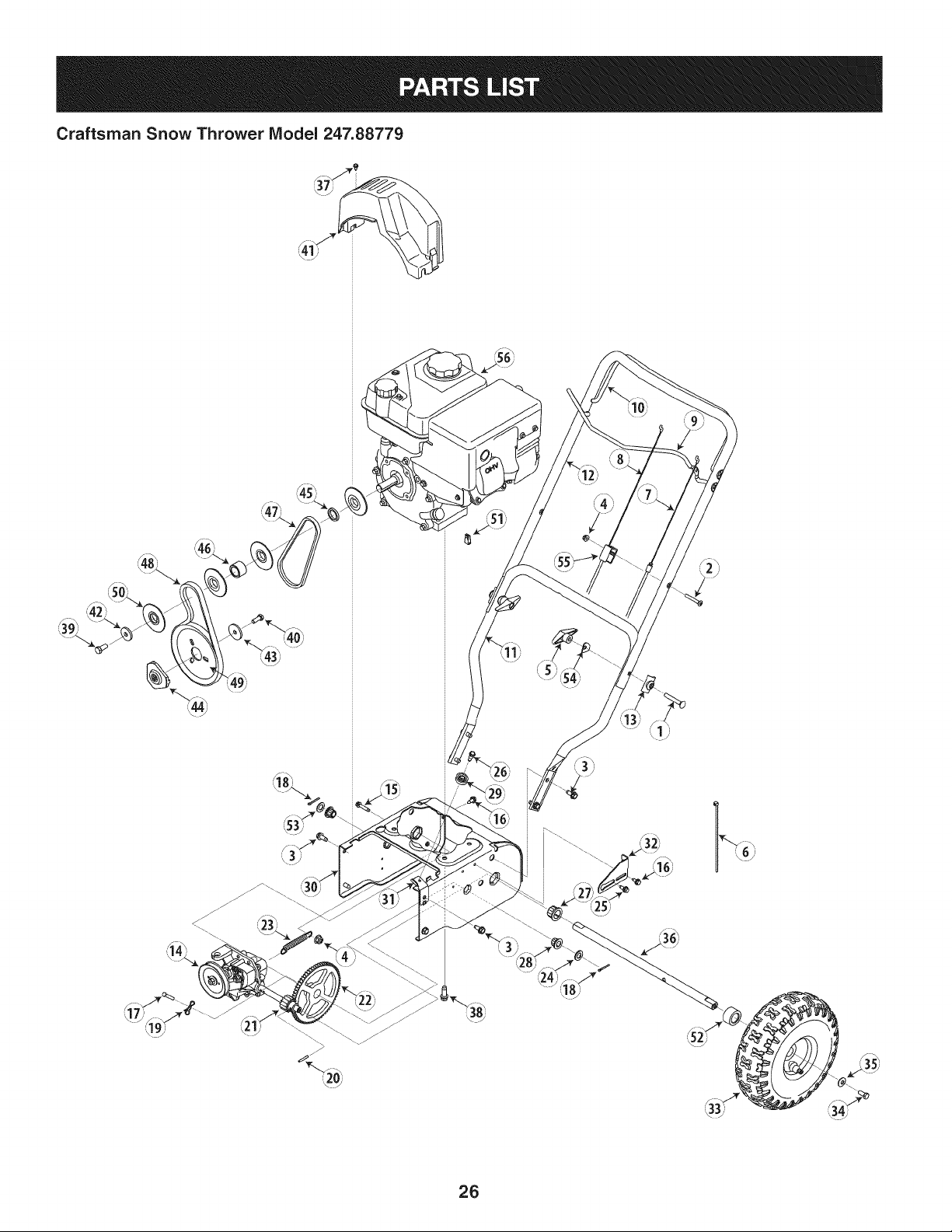
Craftsman Snow Thrower Model 247.88779
777S32636
"lVnNV_ S,UOIVU3dOQV3U"g
"S33VdUnS13AVU9NO_NilVU3dO
N3HMNOJlnV3VHIX33Sn"SU30NVlSA8lV 39HVHOSlO
13_UIGH3A3N'S31UgrNI$133r80 NMOUH1QIOAVOL"_
"3NiHOVW9NIOIAU3SHO9NI9903ON9
3U0:138g:IddOLS3AVHSLUVdONIA0_ITIV'IILNR$3"IQNVH
QNIH_8NiVW3tJONV'3NION]dOlS'SEFIA:FIH31R13_gVON3SJQ"_
"3/RHO39UVHOSIO9013NnO1qO01/OO'NV3lO3Sll "Z
"IBBdQNV SONVHBlVlnd_VNV3UBOnVUOU]ll]dBlHIIAA
IOVINO0"U]OflVONVUB]13d_l 9NIIVIOUWOU__VMVd]B_"L
J
777S32236 777123249
777X43688
........................eeNOT...................
USEE85 ORFUEL
CONTAININGMORE
THAN10% ETHANOL
777122164
i/
777i22138
777D12682
777D12657
777Dl1429
23
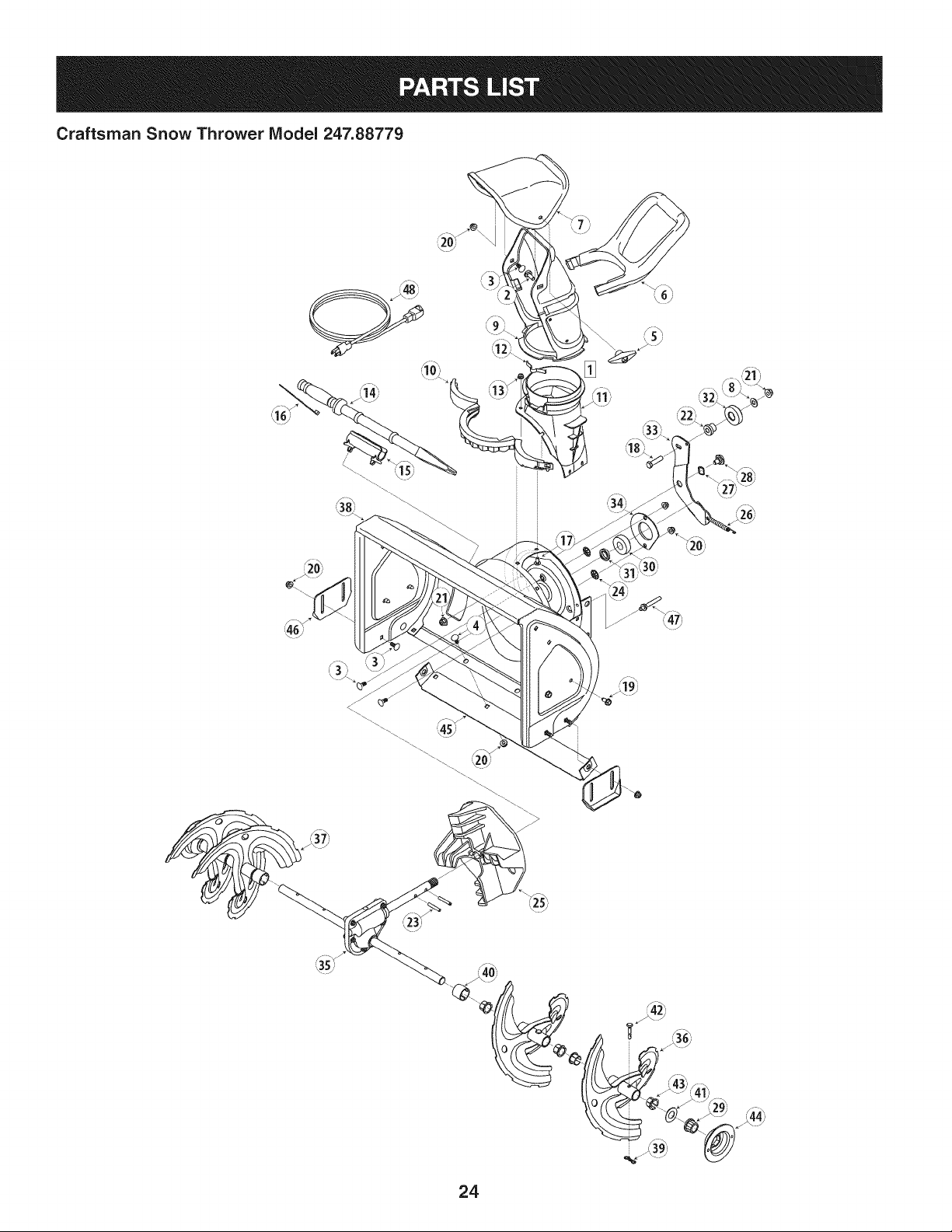
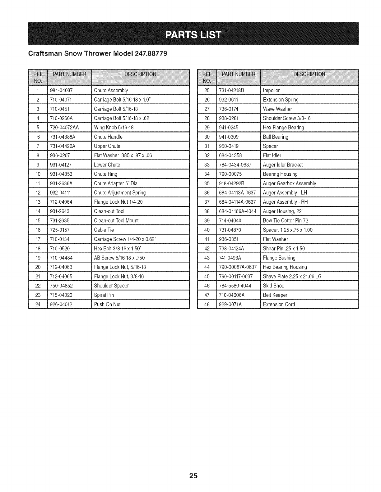
Craftsman Snow Thrower IViodel 247.88779
\
/
24
Craftsman Snow Thrower IViodel 247.88779
iiiiii!ii!ii i !i !ililililiiiiiiii!iiiiiiii!!ii i i!!i!ii! ¸i ili !ii !ii i iiiiiiiiiiiiii!ii!ii!i!!!!!!!!!!!!!!!!!!!!!!!!!!!!!!!!!!!!!!! ii i iii!iii!iiiiiiii i iiiiiiiiiiiiiiiiii ii ii ii ii ii ii ii ii ii ii ii iiiii ii i!!!i!! ! ! ! ! iii ! !i i ! ! !i i! ! !i i i iiii i i i iiiiiiiiiiiiiiiiiiiiiiiiiiiiiiiiiiiiiiiiiiiiiiiiiiiiiiiiiiiiiiiiiiiiiiiiiiiiiiiiiiiiiiiiiiiiiiiiiiiiiiiiiiiiiiiiiiiiiiiiiiiiiiiiiiiiiiiiiiiiiiiiii!i i i
1 984-04037 ChuteAssembly 25
2 710-04071 CarriageBolt 5/16-18x 1.0" 26
3 710-0451 CarriageBolt 5/16-18 27
4 710-0260A CarriageBolt 5/16-18x .62 28
5 720-04072AA WingKnob5/16-18 29
6 731-04388A ChuteHandle 30 941-0309
7 731-04426A UpperChute 31 950-04191
8 936-0267 FiatWasher.385 x .87x .06 32 684-04358
9 931-04127 LowerChute 33 784-0434-0637
10 931-04353 ChuteRing 34 790-00075
11 931-2636A ChuteAdapter5" Dia. 35 918-04292B
12 932-04111 ChuteAdjustmentSpring 36 684-04113A-0637
13 712-04064 FlangeLock Nut 1/4-20 37 684-04114A-0637
14 931-2643 Clean-outTool 38 684-04166A-4044
15 731-2635 Clean-outToolMount 39 714-04040
16 725-0157 CableTie 40 731-04870
17 710-0134 CarriageScrew 1/4-20x 0.62" 41 936-0351
18 710-0520 HexBolt 3/8-16x 1.50" 42 738-04124A
19 710-04484 AB Screw5/16-18x .750 43 741-0493A
20 712-04063 FlangeLock Nut,5/16-18 44 790-00087A-0637
21 712-04065 FlangeLock Nut,3/8-16 45 790-00117-0637
22 750-04852 ShoulderSpacer 46 784-5580-4044
23 715-04020 Spiral Pin 47 710-04606A
24 926-04012 PushOn Nut 48 929-0071A
iiiiiiiiiiiiiiili!:!ili! i i!i!iiii!!iiiiiiii!i!!!iiiiiiii!iiiiiiii!i!i!i_!_!!_!i_!__i__i__i_!_!!!_!___i_!_i_i_i_i!i_!_!_!_i_!_!_!_!_!_!_!_!_!_!_!_!_i_i_i_!_i_i_i!__!_i_i__!!___i!!ii_i!i!i!_!_!___!_!_!_i_ii_i!_i!_i______!___!i_i!_!i!i___!_!!!!!_i!ii!!ii___i__!__i!_!_i_i_i_i!ii__!___!_!__i!_i__i_ii_!_i!i!!ii!!ii!!iiiiiii!ii!!ii!!i!iiiiii!iiiiiiii!iiiiiiiiiiiiii!!ii!!iiii__i_i_!_i_i_i!!_!!!_!!i!i!iiiii!iiii!i!iii!i!iiiiii!ii!!ii!!i!iiiiii!ii!!ii!!i!iiiiii!ii!!ii!!i!iiiiii!ii!!ii!!i!iiiiii!ii!!ii!!i!iiiiii!ii!!ii!!i!iiiiii!ii!!ii!!i!iiiiii!ii!!ii!!i!iiiiii!ii!!ii!!i!iiiiii!ii!!ii!!i!iiiiii!ii!!ii!!i!iiiiii!ii!!ii!!i!iiiiii!ii!!ii!!i!iiiiii!ii!!ii!!i!iiiiii!ii!!ii!!i!iiiiii!ii!!ii!!i!iiiiii!ii!!ii!!i!iiiiii!ii!!ii!!i!iiiiii!ii!!ii!!i!iiiiii!ii!!ii!!i!iiiiii!ii!!ii!!i!iiiiii!ii!!ii!!i!iiiiii!ii!!ii!!i!iiiiii!ii!!ii!i!_i_
731-04218B Impeller
932-0611 ExtensionSpring
736-0174 WaveWasher
938-0281 ShoulderScrew3/8-16
941-0245 Hex FlangeBearing
Ball Bearing
Spacer
FlatIdler
Auger IdlerBracket
BearingHousing
AugerGearboxAssembly
AugerAssembly- LH
AugerAssembly- RH
AugerHousing,22"
Bow Tie Cotter Pin72
Spacer,1.25x.75 x 1.00
FlatWasher
Shear Pin,.25x 1.50
FlangeBushing
Hex BearingHousing
Shave Plate2.25 x 21.66LG
Skid Shoe
Belt Keeper
ExtensionCord
25
Craftsman Snow Thrower Model 247.88779
26
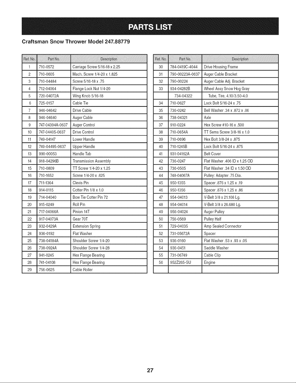
Craftsman Snow Thrower IViodel 247.88779
1 _710-0572 _ CarriageScrew5/16-18x 2.25
2 710-0605 Mach.Screw 1/4-20x 1.825
3 710-04484 Screw5/16-18x .75
4 712-04064 FlangeLock Nut 1/4-20
5 720-04072A WingKnob 5/16-18
6 725-0157 Cable Tie
7 946-04642 DriveCable
8 946-04640 AugerCable
9 747-04394A-0637 AugerControl
10 747-04405-0637 DriveControl
11 749-04147 LowerHandle
12 749-04495-0637 Upper Handle
13 990-00053 HandleTab
14 918-04296B TransmissionAssembly
15 710-0809 TT Screw 1/4-20x 1.25
16 710-1652 Screw1/4-20x .625
17 711-1364 Clevis Pin
18 914-0115 Cotter Pin 1/8x 1.0
19 714-04040 Bow Tie Cotter Pin72
20 915-0249 Roll Pin
21 717-04066A Pinion14T
22 917-04073A Gear70T
23 932-0429A ExtensionSpring
24 936-0192 FiatWasher
25 738-04184A ShoulderScrew1/4-20
26 738-0924A ShoulderScrew1/4-28
27 941-0245 Hex FlangeBearing
28 741-04108 Hex FlangeBearing
29 756-0625 Cable Roller
30 784-0419C-4044 DriveHousingFrame
31 790-00223A-0637 AugerCable Bracket
32 790-00224 AugerCable Adj. Bracket
33 934-04282B Wheel AssySnow HogGray
734-04322 Tube,Tire, 4.10/3.50-4.0
34 710-0627 LockBolt 5/16-24x .75
35 736-0242 BellWasher.34x .872x .06
36 738-04321 Axle
37 910-0224 HexScrew#10-16x .500
38 710-0654A TT SemsScrew 3/8-16x 1.0
39 710-0696 HexBolt 3/8-24x .875
40 710-1245B LockBolt 5/16-24x .875
41 931-04162A BeltCover
42 736-0247 FlatWasher.406ID x 1.25OD
43 736-0505 FlatWasher.34ID x 1.50OD
44 748-04067A Pulley:Adapter.75Dia.
45 950-1355 Spacer .876x 1.25x .19
46 950-1356 Spacer .876x 1.25x .86
47 954-04013 V-Belt 3/8 x 21.108Lg.
48 954-04014 V-Belt 3/8 x 26.680Lg.
49 956-04024 Auger Pulley
50 756-0569 PulleyHalf
51 729-04035 Amp SealedConnector
52 731-05672A Spacer
53 936-0160 FiatWasher.53x .93x .05
54 936-0451 Saddle Washer
55 731-06749 Cable Clip
56 952Z265-SU Engine
27
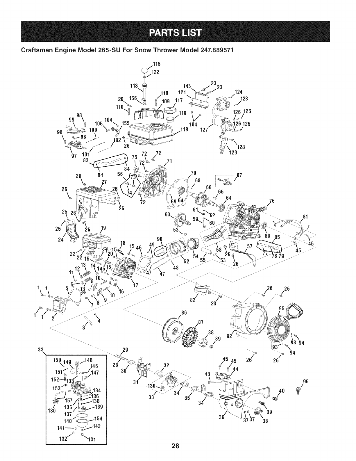
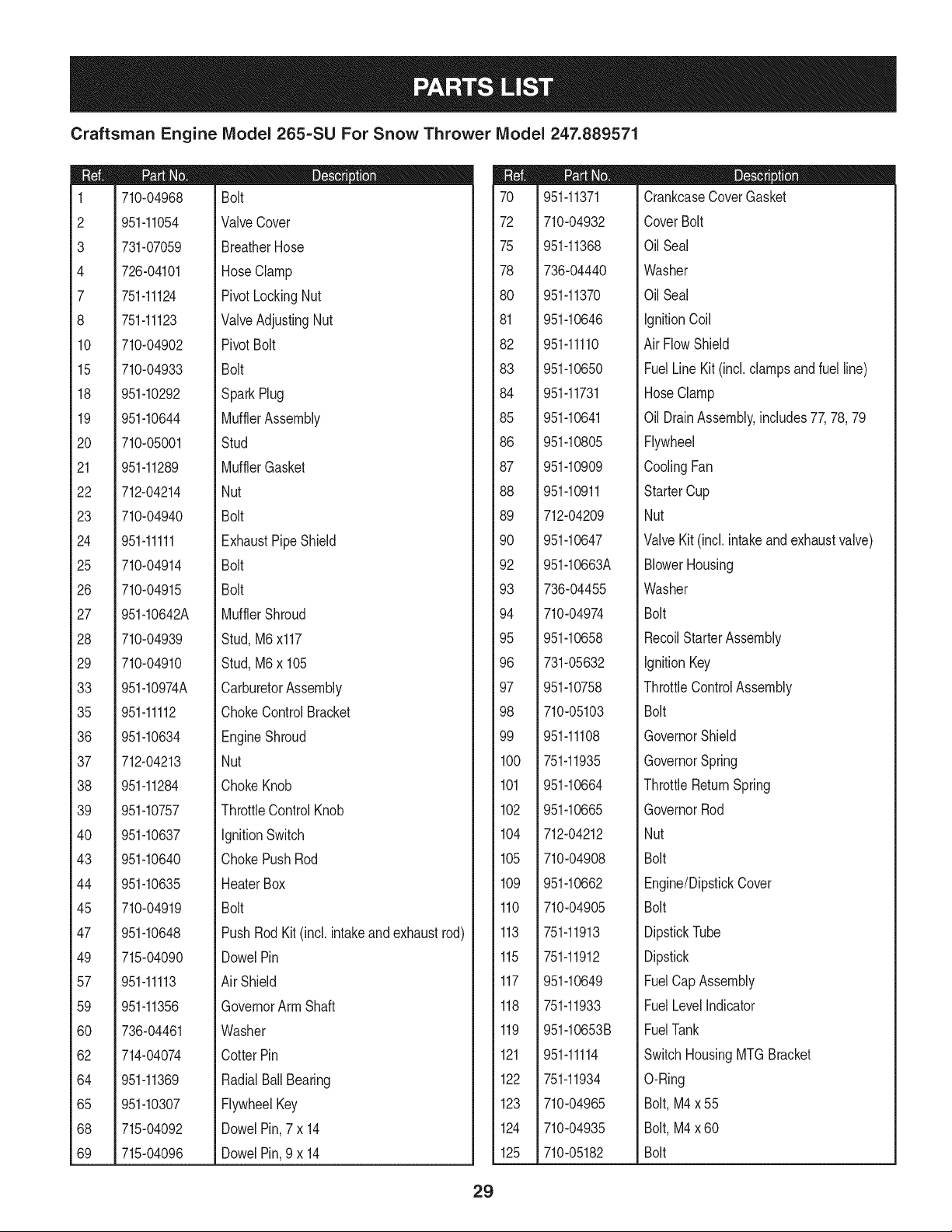
Craftsman Engine Model 265=SU For Snow Thrower Model 247.889571
1/
33
Craftsman Engine IViodel 265=SU For Snow Thrower IViodel 247.889571
m
1
2
3
4
7
8
10
15
18
19
20
21
22
23
24
25
26
27
28
29
33
35
36
37
38
39
40
43
44
45
47
49
57
59
60
62
64
65
68
69
710-04968
951-11054
731-07059
726-04101
751-11124
751-11123
710-04902
710-04933
951-10292
951-10644
710-05001
951-11289
712-04214
710-04940
951-11111
710-04914
710-04915
951-10642A
710-04939
710-04910
951-10974A
951-11112
951-10634
712-04213
951-11284
951-10757
951-10637
951-10640
951-10635
710-04919
951-10648
715-04090
951-11113
951-11356
736-04461
714-04074
951-11369
951-10307
715-04092
715-04096
D = I! O
Bolt
ValveCover
BreatherHose
HoseClamp
PivotLockingNut
ValveAdjustingNut
PivotBolt
Bolt
SparkPlug
MufflerAssembly
Stud
MufflerGasket
Nut
Bolt
ExhaustPipe Shield
Bolt
Bolt
MufflerShroud
Stud,M6x117
Stud,M6x 105
CarburetorAssembly
ChokeControlBracket
EngineShroud
Nut
ChokeKnob
ThrottleControlKnob
IgnitionSwitch
ChokePushRod
HeaterBox
Bolt
PushRod Kit(incl. intakeand exhaustrod)
DowelPin
Air Shield
GovernorArm Shaft
Washer
CotterPin
RadialBall Bearing
FlywheelKey
DowelPin,7 x 14
DowelPin,9 x 14
70
72
75
78
8O
81
82
83
84
85
86
87
88
89
90
92
93
94
95
96
97
98
99
100
101
102
104
105
109
110
113
115
117
118
119
121
122
123
124
125
951-11371
710-04932
951-11368
736-04440
951-11370
951-10646
951-11110
951-10650
951-11731
951-10641
951-10805
951-10909
951-10911
712-04209
951-10647
951-10663A
736-04455
710-04974
951-10658
731-05632
951-10758
710-05103
951-11108
751-11935
951-10664
951-10665
712-04212
710-04908
951-10662
710-04905
751-11913
751-11912
951-10649
751-11933
951-10653B
951-11114
751-11934
710-04965
710-04935
710-05182
D = I! O
CrankcaseCoverGasket
CoverBolt
OilSeal
Washer
OilSeal
ignitionCoil
AirFlowShield
FuelLine Kit (incl.clampsandfuel line)
HoseClamp
OilDrainAssembly,includes77,78,79
Flywheel
CoolingFan
StarterCup
Nut
ValveKit (incl. intakeand exhaustvalve)
BlowerHousing
Washer
Bolt
RecoilStarterAssembly
ignitionKey
ThrottleControlAssembly
Bolt
GovernorShield
GovernorSpring
ThrottleReturnSpring
GovernorRod
Nut
Bolt
Engine/DipstickCover
Bolt
DipstickTube
Dipstick
FuelCapAssembly
FuelLevelindicator
FuelTank
SwitchHousingMTGBracket
O-Ring
Bolt,M4x 55
Bolt,M4x 60
Bolt
29
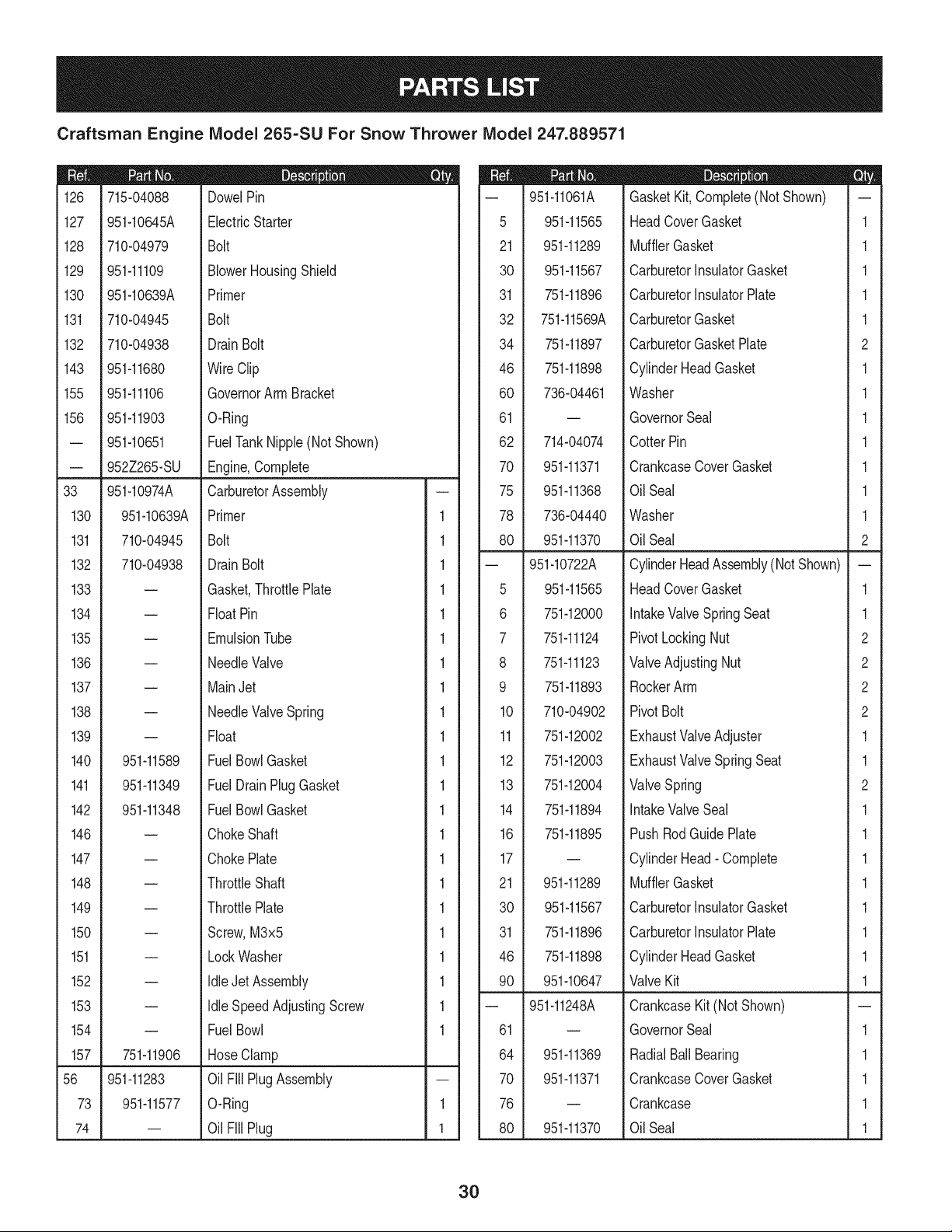
Craftsman Engine Model 265-SU For Snow Thrower Model 247.889571
|- 0 o e
126 715-04088 DowelPin
127 951-10645A ElectricStarter
128 710-04979 Bolt
129 951-11109 BlowerHousingShield
130 951-10639A Primer
131 710-04945 Bolt
132 710-04938 Drain Bolt
143 951-11680 WireClip
155 951-11106 GovernorArm Bracket
156 951-11903 O-Ring
-- 951-10651 FuelTankNipple(NotShown)
-- 952Z265-SU Engine,Complete
33 951-10974A CarburetorAssembly
130 951-10639A Primer 1
131 710-04945 Bolt 1
132 710-04938 Drain Bolt 1
133 = Gasket,ThrottlePlate 1
134 -- FloatPin 1
135 -- EmulsionTube 1
136 = NeedleValve 1
137 = MainJet 1
138 -- NeedleValveSpring 1
139 = Float 1
140 951-11589 FuelBowlGasket 1
141 951-11349 FuelDrain PlugGasket 1
142 951-11348 FuelBowlGasket 1
146 -- ChokeShaft 1
147 = ChokePlate 1
148 = ThrottleShaft 1
149 = ThrottlePlate 1
150 = Screw,M3x5 1
151 -- LockWasher 1
152 -- Idle Jet Assembly 1
153 = Idle SpeedAdjustingScrew 1
154 -- Fuel Bowl 1
157 751-11906 Hose Clamp
56 951-11283 Oil Fill PlugAssembly
73 951-11577 O-Ring 1
74 -- Oil Fill Plug 1
D = O
-- 951-11061A GasketKit,Complete(Not Shown) --
5 951-11565 HeadCoverGasket 1
21 951-11289 MufflerGasket 1
30 951-11567 CarburetorInsulatorGasket 1
31 751-11896 CarburetorInsulatorPlate 1
32 751-11569A CarburetorGasket 1
34 751-11897 CarburetorGasketPlate 2
46 751-11898 CylinderHeadGasket 1
60 736-04461 Washer 1
61 -- GovernorSeal 1
62 714-04074 CotterPin 1
70 951-11371 CrankcaseCoverGasket 1
75 951-11368 OilSeal 1
78 736-04440 Washer 1
80 951-11370 OilSeal 2
-- 951-10722A CylinderHeadAssembly(NotShown) --
5 951-11565 HeadCoverGasket 1
6 751-12000 IntakeValveSpringSeat 1
7 751-11124 PivotLockingNut 2
8 751-11123 ValveAdjustingNut 2
9 751-11893 RockerArm 2
10 710-04902 PivotBolt 2
11 751-12002 ExhaustValveAdjuster 1
12 751-12003 ExhaustValveSpring Seat 1
13 751-12004 ValveSpring 2
14 751-11894 IntakeValveSeal 1
16 751-11895 PushRodGuide Plate 1
17 -- CylinderHead- Complete 1
21 951-11289 MufflerGasket 1
30 951-11567 CarburetorInsulatorGasket 1
31 751-11896 CarburetorInsulatorPlate 1
46 751-11898 CylinderHeadGasket 1
90 951-10647 ValveKit 1
-- 951-11248A CrankcaseKit(NotShown)
61 = GovernorSeal 1
64 951-11369 RadialBall Bearing 1
70 951-11371 CrankcaseCoverGasket 1
76 = Crankcase 1
80 951-11370 OilSeal 1
3O
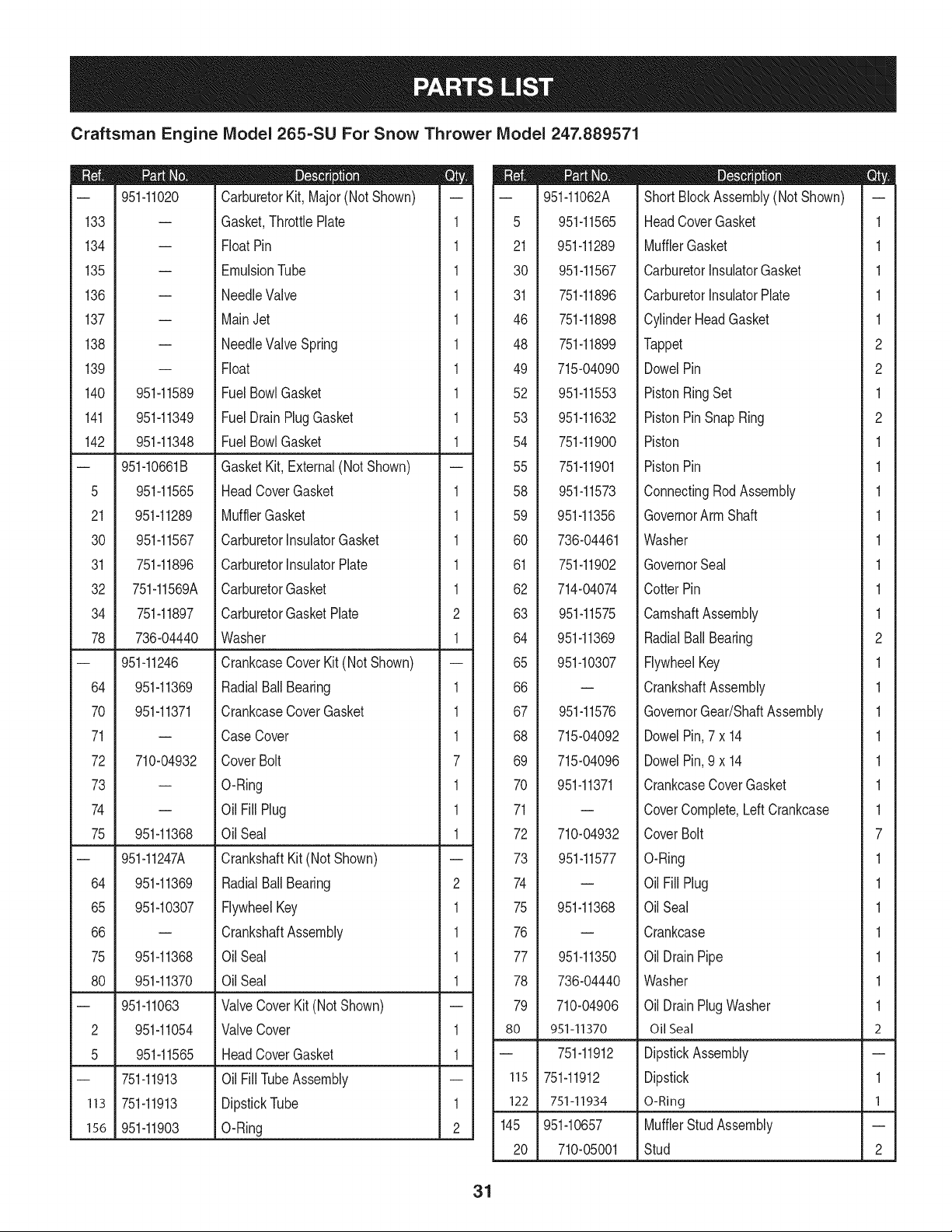
Craftsman Engine IViodel 265-SU For Snow Thrower IViodel 247.889571
|= o= |= 0_
-- 951-11020 CarburetorKit, Major(NotShown) -- -- 951-11062A ShortBlockAssembly(Not Shown) --
133 -- Gasket,ThrottlePlate 1 5 951-11565 HeadCoverGasket 1
134 -- FloatPin 1 21 951-11289 MufflerGasket 1
135 -- EmulsionTube 1 30 951-11567 CarburetorinsulatorGasket 1
136 -- NeedleValve 1 31 751-11896 CarburetorinsulatorPlate 1
137 -- MainJet 1 46 751-11898 CylinderHeadGasket 1
138 -- NeedleValveSpring 1 48 751-11899 Tappet 2
139 -- Float 1 49 715-04090 DowelPin 2
140 951-11589 Fuel BowlGasket 1 52 951-11553 PistonRingSet 1
141 951-11349 Fuel DrainPlugGasket 1 53 951-11632 PistonPinSnapRing 2
142 951-11348 Fuel BowlGasket 1 54 751-11900 Piston 1
-- 951-10661B GasketKit, External(Not Shown) -- 55 751-11901 PistonPin 1
5 951-11565 HeadCoverGasket 1 58 951-11573 ConnectingRodAssembly 1
21 951-11289 MufflerGasket 1 59 951-11356 GovernorArm Shaft 1
30 951-11567 CarburetorinsulatorGasket 1 60 736-04461 Washer 1
31 751-11896 CarburetorInsulatorPlate 1 61 751-11902 GovernorSeal 1
32 751-11569A CarburetorGasket 1 62 714-04074 CotterPin 1
34 751-11897 CarburetorGasketPlate 2 63 951-11575 CamshaftAssembly 1
78 736-04440 Washer 1 64 951-11369 RadialBallBearing 2
-- 951-11246 CrankcaseCoverKit (NotShown) -- 65 951-10307 FlywheelKey 1
64 951-11369 RadialBallBearing 1 66 -- CrankshaftAssembly 1
70 951-11371 CrankcaseCoverGasket 1 67 951-11576 GovernorGear/ShaftAssembly 1
71 -- CaseCover 1 68 715-04092 DowelPin,7 x 14 1
72 710-04932 Cover Bolt 7 69 715-04096 DowelPin,9 x 14 1
73 -- O-Ring 1 70 951-11371 CrankcaseCoverGasket 1
74 -- Oil Fill Plug 1 71 -- CoverComplete,LeftCrankcase 1
75 951-11368 Oil Seal 1 72 710-04932 CoverBolt 7
-- 951-11247A CrankshaftKit (Not Shown) -- 73 951-11577 O-Ring 1
64 951-11369 RadialBallBearing 2 74 -- Oil Fill Plug 1
65 951-10307 FlywheelKey 1 75 951-11368 OilSeal 1
66 -- CrankshaftAssembly 1 76 -- Crankcase 1
75 951-11368 Oil Seal 1 77 951-11350 Oil DrainPipe 1
80 951-11370 Oil Seal 1 78 736-04440 Washer 1
-- 951-11063 ValveCoverKit (Not Shown) -- 79 710-04906 Oil DrainPlugWasher 1
2 951-11054 ValveCover 1 80 951-11370 OilSeal 2
5 951-11565 HeadCoverGasket 1 -- 751-11912 DipstickAssembly --
-- 751-11913 Oil FilITubeAssembly -- 115 751-11912 Dipstick 1
113 751-11913 DipstickTube 1 122 751-11934 O-Ring 1
156 951-11903 O-Ring 2 145 951-10657 MufflerStud Assembly --
20 710-05001 Stud 2
31
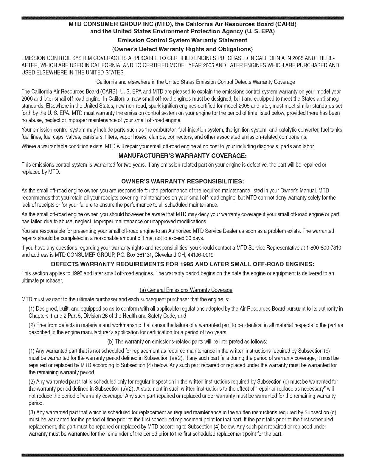
MTD CONSUMER GROUP INC (MTD), the California Air Resources Board (CARB)
and the United States Environment Protection Agency (U. S. EPA)
Emission Control System Warranty Statement
(Owner's Defect Warranty Rights and Obligations)
EMISSIONCONTROLSYSTEMCOVERAGEIS APPLICABLETOCERTIFIEDENGINESPURCHASEDINCALIFORNIAIN2005ANDTHERE-
AFTER,WHICHARE USEDIN CALIFORNIA,ANDTO CERTIFIEDMODELYEAR2005ANDLATERENGINESWHICHARE PURCHASEDAND
USEDELSEWHEREINTHEUNITEDSTATES.
Californiaandelsewherein the UnitedStatesEmissionControlDefectsWarrantyCoverage
The CaliforniaAir ResourcesBoard(CARB),U.S. EPAand MTDarepleasedto explaintheemissionscontrolsystemwarrantyonyour modelyear
2006andlatersmalloff-roadengine.In California,new smalloff-roadenginesmustbe designed,builtand equippedto meet theStatesanti-smog
standards.Elsewherein the UnitedStates,newnon-road,spark-ignitionenginescertifiedfor model2005and later,mustmeet similarstandardsset
forthby the U. S. EPA.MTDmustwarrantythe emissioncontrolsystemon yourenginefor the periodof time listed below,providedtherehasbeen
noabuse,neglector impropermaintenanceof your smalloff-roadengine.
Youremissioncontrolsystemmayincludepartssuch as the carburetor,fuel-injectionsystem,the ignitionsystem,andcatalyticconverter,fueltanks,
fuel lines,fuel caps,valves,canisters,filters,vaporhoses,clamps,connectors,and otherassociatedemission-relatedcomponents.
Wherea warrantableconditionexists,MTDwill repairyoursmall off-roadengineat no cost to yourincludingdiagnosis,partsand labor.
MANUFACTURER'S WARRANTY COVERAGE:
Thisemissionscontrolsystemis warrantedfor twoyears.If anyemission-relatedpart on yourengineis defective,the part will berepairedor
replacedby MTD.
OWNER'S WARRANTY RESPONSIBILITIES:
As the smalloff-roadengineowner,youare responsibleforthe performanceof the requiredmaintenancelisted in your Owner'sManual.MTD
recommendsthatyou retainall yourreceiptscoveringmaintenanceson yoursmall off-roadengine,but MTDcan not denywarrantysolelyfor the
lackof receiptsor for yourfailureto ensurethe performanceto allscheduledmaintenance.
As the smalloff-roadengineowner,youshouldhoweverbeawarethat MTDmaydenyyour warrantycoverageif yoursmall off-roadengineor part
hasfaileddue toabuse,neglect,impropermaintenanceor unapprovedmodifications.
Youare responsiblefor presentingyour smalloff-roadengineto an AuthorizedMTDServiceDealeras soonas a problemexists.Thewarranted
repairsshouldbe completedin a reasonableamountof time,notto exceed30 days.
If youhaveanyquestionsregardingyourwarrantyrightsand responsibilities,you shouldcontacta MTDService Representativeat 1-800-800-7310
andaddressis MTDCONSUMERGROUP,RO.Box361131,ClevelandOH,44136-0019.
DEFECTS WARRANTY REQUIREMENTS FOR 1995 AND LATER SMALL OFF-ROAD ENGINES:
Thissectionappliesto 1995and later smalloff-roadengines.The warrantyperiodbeginson the datethe engineor equipmentis deliveredto an
ultimatepurchaser.
(a) GeneralEmissionsWarrantyCoverage
MTDmustwarrantto the ultimatepurchaserand eachsubsequentpurchaserthatthe engineis:
(1)Designed,built,and equippedsoas to conformwithallapplicableregulationsadoptedby the Air ResourcesBoardpursuantto itsauthorityin
Chapters1 and 2,Part 5, Division26of the Healthand SafetyCode;and
(2) Freefromdefectsin materialsand workmanshipthat causethe failureof a warrantedpart to be identicalin all materialrespectsto the partas
describedin theenginemanufacturer'sapplicationfor certificationfora periodof twoyears.
(b)The warrantyonemissions-relatedpartswill be interpretedas follows:
(1)Anywarrantedpart thatis not scheduledfor replacementas requiredmaintenanceinthe writteninstructionsrequiredby Subsection(c)
mustbe warrantedfor the warrantyperioddefinedinSubsection(a)(2). If any such partfailsduringthe periodof warrantycoverage,it mustbe
repairedor replacedby MTDaccordingto Subsection(4)below.Anysuch part repairedor replacedunder thewarrantymustbewarrantedfor
the remainingwarrantyperiod.
(2)Any warrantedpartthat is scheduledonlyfor regularinspectioninthe writteninstructionsrequiredby Subsection(c) mustbe warrantedfor
thewarrantyperioddefinedin Subsection(a)(2).A statementinsuchwritteninstructionsto the effect of"repairor replaceas necessary"will
not reducethe periodof warrantycoverage.Anysuchpart repairedor replacedunderwarrantymustbe warrantedforthe remainingwarranty
period.
(3) Anywarrantedpartthat whichis scheduledfor replacementas requiredmaintenancein the writteninstructionsrequiredby Subsection(c)
mustbe warrantedfor the periodof time prior to the first scheduledreplacementpointforthat part. If the part fails prior to thefirst scheduled
replacement,the part mustbe repairedor replacedby MTDaccordingto Subsection(4) below.Any suchpart repairedor replacedunder
warrantymustbewarrantedfor the remainderof the period priorto the first scheduledreplacementpointfor the part.
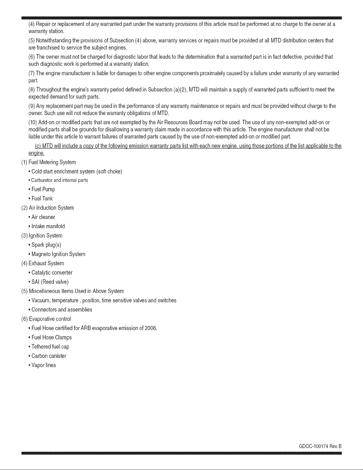
(4)Repairorreplacementofanywarrantedpartunderthewarrantyprovisionsofthisarticlemustbeperformedatnochargetotheownerata
warrantystation.
(5)NotwithstandingtheprovisionsofSubsection(4)above,warrantyservicesorrepairsmustbeprovidedatallMTDdistributioncentersthat
arefranchisedtoservicethesubjectengines.
(6)Theownermustnotbechargedfordiagnosticlaborthatleadstothedeterminationthatawarrantedpartisinfactdefective,providedthat
suchdiagnosticworkisperformedatawarrantystation.
(7)Theenginemanufacturerisliablefordamagestootherenginecomponentsproximatelycausedbyafailureunderwarrantyofanywarranted
part.
(8)Throughouttheengine'swarrantyperioddefinedinSubsection(a)(2),MTDwillmaintaina supplyofwarrantedpartssufficienttomeetthe
expecteddemandforsuchparts.
(9)Anyreplacementpartmaybeusedintheperformanceofanywarrantymaintenanceorrepairsandmustbeprovidedwithoutchargetothe
owner.SuchusewillnotreducethewarrantyobligationsofMTD.
(10)Add-onormodifiedpartsthatarenotexemptedbytheAirResourcesBoardmaynotbeused.Theuseofanynon-exemptedadd-onor
modifiedpartsshallbegroundsfordisallowingawarrantyclaimmadeinaccordancewiththisarticle.Theenginemanufacturershallnotbe
liableunderthisarticletowarrantfailuresofwarrantedpartscausedbytheuseofnon-exemptedadd-onormodifiedpart.
(c) MTDwill includea copyof the followingemissionwarrantypartslistwitheach newengine,usingthoseportionsof the list applicableto the
e__&gine.
(1)FuelMeteringSystem
• Coldstart enrichmentsystem(soft choke)
,,Carburetorandinternalparts
• Fuel Pump
• FuelTank
(2)Air InductionSystem
• Aircleaner
• Intakemanifold
(3) IgnitionSystem
• Sparkplug(s)
• MagnetoIgnitionSystem
(4)ExhaustSystem
Catalyticconverter
• SAI (Reedvalve)
(5) MiscellaneousItemsUsedin AboveSystem
Vacuum,temperature, position,timesensitivevalvesand switches
Connectorsandassemblies
(6) Evaporativecontrol
• Fuel Hosecertifiedfor ARBevaporativeemissionof 2006.
• Fuel HoseClamps
Tetheredfuel cap
Carboncanister
Vaporlines
GD0C-100174Rev.B
Look For Relevant Emissions Durability Period and
Air index information On Your Engine Emissions Label
Engines that are certified to meet the California Air Resources Board (CARB) Tier 2 Emission Standards must
display information regarding the Emissions Durability Period and the Air Index. Sears Brands Management
Corporation makes this information available to the consumer on our emission labels.
The Emissions Durability Period describes the number of hours of actual running time for which the engine is
certified to be emissions compliant, assuming proper maintenance in accordance with the Operating & Mainte-
nance Instructions. The following categories are used:
Moderate: Engine is certified to be emission compliant for 125 hours of actual engine running time.
Intermediate: Engine is certified to be emission compliant for 250 hours of actual engine running time.
Extended: Engine is certified to be emission compliant for 500 hours of actual engine running time.
For example, a typical walk-behind lawn mower is used 20 to 25 hours per year. Therefore, the Emissions
Durability Period of an engine with an intermediate rating would equate to 10 to 12 years.
The Air index is a calculated number describing the relative level of emissions for a specific engine family. The
lower the Air Index, the cleaner the engine. This information is displayed in graphical form on the emissions label.
After July 1,2000, Look For Emissions Compliance Period
On Engine Emissions Compliance Label
After July 1, 2000 certain Sears Brands Management Corporation engines will be certified to meet the United
States Environmental Protection Agency (USEPA) Phase 2 emission standards. For Phase 2 certified engines, the
Emissions Compliance Period referred to on the Emissions Compliance label indicates the number of operating
hours for which the engine has been shown to meet Federal emission requirements.
For engines less than 225 cc displacement, Category C = 125 hours, B = 250 hours and A = 500 hours.
For engines of 225 cc or more, Category C = 250 hours, B = 500 hours and A = 1000 hours.
This is a generic representation of the emission label typically found on a certified engine.
FAMILYYBSXS.3192VA 274812
GDOC-100182Rev.B
34
Congratulationson makinga smartpurchase.YournewCraftsman@
productis designedandmanufacturedfor yearsof dependableopera-
tion.But likeall products,it mayrequirerepairfromtimeto time.That's
whenhavinga RepairProtectionAgreementcansaveyoumoneyand
aggravation.
Here'swhatthe RepairProtectionAgreement*includes:
* Expert service byour 10,000professionalrepairspecialists
o Unlimitedserviceand no chargefor partsand laboron all
coveredrepairs
o Product replacementupto $1500if yourcoveredproductcan'tbe
fixed
• Discountof 10%from regularprice of serviceand relatedinstalled
partsnotcoveredby theagreement;also,10%off regularpriceof
preventivemaintenancecheck
• Fast help by phone- we call it RapidResolution- phonesupport
froma Searsrepresentative.Thinkof usas a "talkingowner's
manual."
Onceyou purchasethe Agreement,a simplephonecall is all that it
takesfor youto scheduleservice.Youcan call anytimedayor night,or
schedulea serviceappointmentonline.
The RepairProtectionAgreementis a risk-freepurchase.If youcancel
for any reasonduringthe productwarrantyperiod,wewill providea full
refund.Or,a proratedrefundanytimeafterthe productwarrantyperiod
expires.Purchaseyour RepairProtectionAgreementtoday!
Somelimitationsand exclusionsapply. For pricesand additional
informationin the U.S.A. call 1-800-827-6655.
*Coverage in Canadavaries on some items.Forfull details call
Sears Canadaat 1-800-361-6665.
Sears Installation Service
ForSearsprofessionalinstallationof homeappliances,garagedoor
openers,waterheaters,and othermajorhomeitems,in the U.S.A.or
Canadacall 1-800-4-MY-HOME®.
35
Declaraci6n de garantia ............................ Pagina 36
Practicas operaci6n seguras ..................... Pagina 37
Etiquetas de seguridad .............................. Pagina 40
Montaje ...................................................... Pagina 41
Operaci6n .................................................. Pagina 45
Servicio y Mantenimiento .......................... Pagina 49
Almacenamiento fuera de temporada ....... Pagina 54
Soluci6n de problemas .............................. Pagina 55
Lista de piezas ........................................... Pagina 23
Acuerdo de protecci6n para reparaciones .... Pagina 59
NOmero de servicio ................................... Pagina 60
ARTESANA COIViPLETA GARANTIA
Cuandoson operadosy mantenidosde acuerdocon lasinstruccionessuministradasen sutotalidad,si la nieveestaArtesanolanzadorfalladebido a un defecto
de materialo manode obra dentrode dos a_osa partirde la fechade compra,el retornoa cualquiertiendaSears, Searspartesdel Centrode Servicioy
Reparaci6n,u otrosArtesanosalidaen los EstadosUnidospara la reparaci6ngratuita(si lareparaci6no la sustituci6nresulteimposible).
Esta garanfiaseaplica s61opara90 d[asa partir de la fechade comprasi esta astilladorade fragmentaci6ncadavez es utilizadoparaprop6sitoscomercialeso
de alquiler.
Esta garantias61ocubre defeetos de material y mano deobra.Sears no pagar_pot:
• Los elementosquese desgastanduranteel uso normal,incluyendopero no limitadoa
,, barrenapalaso remos,zapatosantideslizantes,afeitarselaplaca,los pinesde cizalla,buj[as,filtro de aire,cinturones,y filtro de aceite.
• Normade serviciosde mantenimiento,cambiosde aceite,o afinaci6n.
• Cambiode neum_ticosde sustituci6no reparaci6nde pinchazoscausadospotobjetosexternos,tales comoclavos,espinas,tocones,o de vidrio.
• De neum_ticoso ruedasde reemplazoo la reparaci6ncomoconsecuenciade desgastenormal,accidente,o de la malaoperaci6no mantenimiento.
• Reparacionesque seannecesariasa causade losabusosdel operador,incluyendopero no limitadoa losdaSoscausadospot el excesodevelocidaddel
motor,o de objetosqueimpactandoblarla barrena,elchasiso cigQe_al.
• Reparacionesque seannecesariasa causade la negligenciadel operador,incluyendopero no limitadoa, productoselectricosy mecanicosde losda_os
causadosporalmacenamientoinadecuado,falta de utilizaci6nde la categor[aapropiaday la cantidadde aceitede motor,o el fracasopara mantenerel
equipode acuerdocon las instruccionescontenidasen el manualdel operador.
• Motor(sistemade combustible),lalimpiezao reparacionescausadaspor loscombustiblesdecididaa set contaminadoso oxidado(rancio).Engeneral,el
combustibledebeset utilizadodentrode los30 d[as siguientesa su fechade compra.
,, Normaldesgastey deteriorode los acabadosexteriores,o la etiquetadel productode reemplazo.
Esta garantias61ose aplica mientrasqueesteproductoest_dentrode los EstadosUnidos.
Esta garantiale otorgaderechoslegalesespecificos,y ustedtambienpuedetenet otrosderechosquevariande estadoa estado.
Sears, Roebuck and Co., Hoffman Estates, IL 60179
Tipode aceite del motor:
Capacidadde aceitedel motor:
Capacidadde combustible:
Bujias:
Separaci6nde las bujias:
5W-30
20 onzas
2.3 cuartos
Torch F6RTC (F6TC)
.020" to .030"
N_mero de modelo ..........................................................
N_mero de serie ..............................................................
Fechade compra .............................................................
Registrearribael nOmerodel modelo,el nOmerode seriey la fecha
de compra
© Sears Brands,LLC
36
Lapresenciadeeste sfrnboloindicaque setratade instrucciones
irnportantesde seguridadque se debenrespetarpara evitar
ponerenpeligrosu seguridadpersonaly/o materialy lade otras
personas.Lea y siga todaslas instruccionesde este manualantes
de poneren funcionarnientoestarn_.quina.Si no respetaestas
instruccionespodrfaprovocarlesionespersonales.Cuandoveaeste
sfrnbolo,i presteatenci6na la advertencia!
PROPOSICION 65 DE CALIFORNIA
Elescapedel motordeesteproducto,algunosde suscornponentes
y algunoscornponentesdelvehfculocontieneno liberansustancias
qufrnicasque el estado de Californiaconsideraque puedenproducir
c_.ncer,defectosde nacirnientouotrosproblernasreproductivos.
Estarn_.quinarue construidaparaseroperadadeacuerdocon
las reglasde seguridadcontenidasen este manual.AI igualque
concualquiertipo de equipo rnotorizado,undescuidoo errorpor
partedel operadorpuedeproducirlesionesgraves.Estarn_.quina
es capazde arnputarrnanosy piesy de arrojarobjetoscon gran
fuerza.Deno respetarlas instruccionesde seguridadsiguientesse
puedenproducirlesionesgraveso larnuerte.
Su responsabilidad--Restrinja el usode estarn_.quina
rnotorizadaalas personasque lean,cornprendany respetenlas
advertenciase instruccionesqueaparecenen estemanualyen la
rn_.quina.
iGUARDEESTASINSTRUCCIONES!
CAPACITACI6N
• Lea,entienday curnplatodaslas instruccionesincluidasen
la rn_.quinay en los rnanualesantesdernontarlay utiNzarla.
Guardeestemanualen un lugarseguroparaconsultasfuturasy
peri6dicas,asf cornopara solicitarrepuestos.
• Leael Manualdel Operadory sigatodaslas advertenciase
instruccionesde seguridad.Elfracasode hacerasf puedecausar
la heridaseriaal operadory/o personaspresentes.Paraflarnada
depreguntas,1-800-4MY-HOME.
• Farniliarfcesecontodoslos controlesy con el usoadecuado
delos rnisrnos.Sepac6rnodetenerlarn_.quinay desactivarlos
controlesr_.pidarnente.
• No perrnitanuncaque los ni_osrnenoresde 14a_osutilicen
estarn_.quina.Los nifios de 14afiosen adelantedeben leer y
entenderlas instruccionesde operaci6ny norrnasdeseguridad
contenidasen este manual,yen la rn_.quinaydebenser entrena-
dosy supervisadospor un adulto.
• Nuncaperrnitaquelos adultosoperenesta rn_.quinasin recibir
antesla instrucci6napropiada.
• Losobjetosarrojadospor la rn_.quinapuedenproducirlesiones
graves.Planifiqueel patr6nenel que va a ir arrojandonievepara
evitarque ladescargade materialse realicehacialos carninos,
los observadores,etc.
• Mantengaa losobservadores,ayudantes,rnascotasy ni_ospor
Io rnenosa 75 piesde la rn_.quinarnientrasla rnisrnaest,.en
funcionarniento.Detengala rn_.quinasi alguienseacerca.
• Seaprecavidoparaevitarpatinarseo caerseespecialrnente
cuandoopera la rn_.quinaen reversa.
PR E PARATIVO S
Inspeccionerninuciosarnenteel &teadondeutilizar&el equipo.Saque
todoslos felpudos,peri6dicos,trineos,tablas,cablesy otros objetos
extra_oscon los quepodrfatropezaro quepodrfanser arrojadospor
labarrena/irnpulsor.
• Paraprotegerselosojos utilice siernpreanteojoso antiparras
de seguridadrnientrasoperala rn_.quinao rnientrasla ajusta
o repara.Losobjetosarrojadosque rebotanpuedenproducir
lesionesocularesgraves.
• Nooperelarn_.quinasin la vestirnentaadecuadaparaestar al
airelibreen invierno.No utilicealhajas,bufandaslargasu otras
prendassueltasquepodrfanenredarseenlas partes rn6viles.
UtiNceun calzadoespecialpara superficiesresbaladizas.
• Useun prolongadory untornacorrientedetrescablescon
conexi6na tierraparatodas las rn_.quinascon rnotoresde
encendidoel_ctrico.
• Ajustela alturade la caja del tornacorrientepara Nrnpiarla grava
o las superficiescon piedrastrituradas.
• Desengranetodaslas palancasde controlantesde arrancarel
motor.
• Nuncaintenterealizarajustesrnientrasel motorest,.enrnarcha
exceptoen los casosespecfficarnenterecornendadosen el
manualdel operador.
• Dejequeelmotory la rn_.quinase adaptena la ternperatura
exteriorantesde cornenzara sacarla nieve.
37
Manejo seguro de la gasolina
Paraevitarlesionespersonales0 daSosrnaterialestengarnucho
cuidadocuandotrabajecon gasolina.Lagasolinaes surnarnente
inflarnabley sus vaporespuedencausarexplosiones.Si se derrarna
gasolinaencirna0 sobrela ropase puedelesionargravernenteya que
se puedeincendiar. L&vesela piely c&rnbiesede ropade inrnediato.
• Utilices610los recipientesparagasolinaautorizados.
• Apaguetodos los cigarrillos,cigarros,pipasy otrasfuentesde
cornbusfi6n.
• Nuncacarguecombustibleen larn&quinaen un espaciocerrado.
• Nuncasaquela tapadel combustibleniagreguecombustible
rnientrasel motorest&caliente0 en rnarcha.
• Dejequeel motorse enfriepor I0 rnenosdos rninutosantesde
volvera cargarcombustible.
• NuncaIleneenexcesoel dep6sitodecombustible.Lleneel
tanquea no rn&sde 1/2pulgadapordebajode la basedelcuello
de Ilenadodejandoespaciopara la dilataci6ndeIcombustible.
• Vuelvaa colocarla tapade la gasoiinay aj_stelabien.
• Lirnpieel combustibleque se hayaderrarnadosobreel motory el
equipo.Trasladela rn&quinaa otra zona.Espere5 rninutosantes
deencenderel motor.
• Nuncaalrnacenela rn&quina0 el recipientedecombustibleen
unespaciocerradodonde hayafuego,chispas0 luz piloto(por
ejernplo,hornos,calentadoresdeagua,calefactores,secadores
de ropa,etc.).
• Dejequela rn_.quinase enfrieporIo rnenos5 rninutosantesde
guardarla.
• NuncaIlenelos recipientesenel interiordeunvehiculoo carni6n
ocaja de rernolquecon recubrirnientospl_.sticos.Coloque
siernprelos recipientesenel pisoy lejosdel vehiculoantesde
Ilenarlos.
• Sies posible,retireel equipoa gasolinadelcarni6no rernolque
y II_neloen el suelo.Siestonoes posible,Ileneel equipoen un
rernolquecon contenedorport_.til,en vez de desdeunaboquilla
dispensadoradegasolina.
• Mantengala boquilladispensadoraen contactocon el hordedel
dep6sitode combustibleo con la aberturadel recipienteentodo
rnornento,hastaterrninarla carga. No utiliceun dispositivode
apertura/cierrede boquilla.
FUNCIONANIIENTO
• No pongalas rnanoso los piescercadelas piezasrotatorias,
en lacajade la barrena/ irnpulsoro en el rnontajedel canalde
descarga.Hacercontactocon piezasgiratoriaspuederesultaren
laarnputaci6ndernanoso pies.
• La palancade controlde la barrena/ irnpulsores un dispositivo
de seguridad.Nuncaevitesu funcionarniento.De hacerlola
operaci6nde la rn_.quinaes riesgosay puedeocasionarlesiones.
• Las palancasde control debenfuncionarbienen arnbasdirec-
cionesy regresarautorn_.ticarnentea la posici6nde desengrane
cuandose lassuelta.
• Nuncaoperela rn_.quinasi faltaunrnontajedelcanalo si el
rnisrnoest,. daSado.Mantengatodos losdispositivosde seguri-
daden su lugaryen funcionarniento.
• Nuncaenciendaelmotorenespacioscerradoso en unazona
con pocaventilaci6n.El escapedel motorcontienernon6xidode
carbono,ungas inodoroy letal.
• Noutilicela rn_.quinabajola influenciadel alcoholo las drogas.
• El silenciadory el motorse calientany puedencausarquernadu-
ras.Nolos toque.Mantengaa los niSosalejados.
• Seasurnarnenteprecavidocuandooperelarn_.quinasobreuna
superficiecon gravaocuandola cruce.Mant_ngasealerta por si
se presentanpeligrosocultoso tr_.nsito.
• Tengacuidadocuandocarnbiede direcci6no cuandooperela
rn_.quinaen pendientes.
• Planifiqueel patr6nenel queva air arrojandonieveparaevitar
que ladescargade materialse produzcahacialas ventanas,
las paredes,losautorn6viles,etc.y evitarasi posiblesdaSos
rnaterialeso lesionesproducidasporlos rebotes.
• Nuncadirija la descargahacialos niSos,los observadoreso las
rnascotasni deje que nadiese pare delantede la rn_.quina.
• Nosobrecarguela capacidadde la rn_.quinatratandode sacarla
nievernuyr_.pidarnente.
• Nuncaopereesta rn_.quinasin buenavisibilidado ilurninaci6n.
Siernpredebeestarsegurode queest,.bienafirrnadoy su-
jetandofirrnernentelas rnanijas.Carnine,nuncacorra.
• Cortela corrientea la barrena/ irnpulsorcuandotransportela
rn_.quinao cuandolarnisrnanoest,.en uso.
• Nuncaoperela rn_.quinaa alta velocidadde desplazarniento
sobresuperficiesresbaladizas.Mirehaciaabajoy haciaatr_.sy
tengacuidadocuandovaya rnarchaatr_.s.
• Si la rn_.quinacornenzaraa vibrarde rnaneraanorrnal,detengael
motor,desconecteel cablede la bujia y p6ngalade rnaneraque
hagarnasacontra el motor.Inspeccionela rn_.quinarninuciosa-
rnenteparaver si est,.daSada.Reparetodos los daSosantesde
encendery operar la rn_.quina.
• Desengranetodas las palancasde controly detengaelmotor
antesdedejarla posici6nde operaci6n(detr_.sde las rnanijas).
Esperea que labarrena/ irnpulsorse detengapor cornpleto
antesdedestaparelrnontajedel canalo realizarajustese
inspecciones.
• Nuncapongalas rnanosenlas aberturasde descargao de
recolecci6n.Utilicesiernprela herrarnientade lirnpiezaquese
adjuntaparadestaparla aberturadedescarga.Nodestapeel
rnontajedel canal rnientrasel motorest,. en funcionarniento.
Antesde destaparlo,apagueel motory perrnanezcadetr_.sde las
rnanijashastaque todaslas partes rn6vilesse hayandetenido.
• Uses61ounionesy accesoriosaprobadosporel fabricante(por
ejernplo,pesaspara las ruedas,cadenaspara los neurn_.ticos,
cabinas,etc.).
38
• Paraencenderel motor,jale de la cuerdalentarnentehastaque
sientaresistencia,luegojale r_.pidarnente.Elreplieguer_.pidode
la cuerdade arranque(tensi6nde retroceso)lejalar_,la rnanoy
el brazohaciael motor rn_.sr_.pidodeIo que usted puedesoltar.
El resultadopuedenserhuesosrotos,fracturas,hernatornaso
esguinces.
• Si se presentansituacionesque no est_.nprevistasen este
manual,seacuidadosoy use el sentidocornOn.P6ngaseen
contactocon Asistenciaal Clienteparasolicitarayuday el
nornbredeldistribuidorde serviciorn_.scercano.
MANTENIMIENTO Y ALMACENAMIENTO
• Nuncaalterelos dispositivosde seguridad.Controleperi6dica-
rnenteque funcionencorrectarnente.Rernitasealas secciones
demantenirnientoy ajustede estemanual.
• Antesde realizarla lirnpieza,repararo revisarla rn_.quina,
desengranetodas laspalancasdecontroly detengael motor.
Esperea quela barrena/ irnpulsorse detengaporcornpleto.
Desconecteel cabledela bujfay p6ngalohaciendornasacontra
el motorparaevitarquese enciendaaccidentalrnente.
• Controlefrecuenternentequetodoslospernosy tornillosest_n
bienajustadosparacornprobarquela rn_.quinase encuentra
encondicionessegurasde funcionarniento.Adern_.s,hagauna
inspecci6nvisual de larn_.quinaparaverificarsi est,. da_ada.
• No carnbielaconfiguraci6ndel reguladordelmotorni acelere
dernasiadoel rnisrno.El reguladordelmotorcontrolala velocidad
rn_.xirnasegurade funcionarnientodel motor.
• Las placasde raspadoy las zapatasantideslizantesquese
usancon la rn_.quinaquitanievese desgastany se da_an.
Paraprotegersu seguridad,verifiquefrecuenternentetodos los
cornponentesy reernpl_.celoss61ocon partesde los fabricantes
deequiposoriginales(OEM)."i Elusode piezasquenocurnplen
con lasespecificacionesdelequipooriginalpuederesultaren
rendirnientoinadecuadoadern_.sde poneren riesgola seguri-
dad!"
• Reviselas palancasde controlperi6dicarnentepara verificar
queengraneny desengranenadecuadarnentey ajOstelossi es
necesario.Consultela secci6nde ajustesde este manualdel
operadorparaobtenerinstrucciones.
• Mantengao reernplacelasetiquetasde seguridade instrucciones
segQnseanecesario.
• Respetelas norrnasreferentesa la disposici6ncorrectay las
reglarnentacionessobregasolina,aceite,etc. para protegerel
medicarnbiente.
• Antesdealrnacenarlarn_.quinaenci_ndalaunosrninutospara
sacarla nieveque hayaquedadoen larnisrnay paraevitarasi
quese congelela barrena/irnpulsor.
• SegOnla Cornisi6nde Seguridadde Productosparael Consu-
rnidorde los EstadosUnidos(CPSC)y la Agenciade Protecci6n
Arnbientalde los EstadosUnidos(EPA),este productotieneuna
vida Qtilmediade siete (7) a_os, 6 60 horasde funcionarniento.
AI finalizarla vida Otilmedia,adquieraunarn_.quinanuevao
hagainspeccionaranualrnente_sta por un distribuidordeservicio
autorizadoparacerciorarsede quetodoslos sisternasrnec_.nicos
y deseguridadfuncionancorrectarnentey no tienenexcesivo
desgaste.Si no Iohace,puedenproducirseaccidentes,lesiones
o rnuerte
• Nuncaalrnacenela rn_.quinao el recipientedecombustibleen un
espaciocerradodondehayafuego,chispaso luz pilotocornopor
ejernplo,calentadoresde agua,hornos,secadoresde ropa,etc.
• Consultesiernpreel manualdel operadorparaobtener
instruccionesadecuadaspara el alrnacenarnientofuerade
ternporadaVerifiquefrecuenternentelaIfneade combustible,el
tanque,el tap6n,y losaccesoriosbuscandorajaduraso perdidas.
Reernplacede ser necesario.
• Nod_ arranqueal motorsi no est,. la bujia de encendido.
NO MODIFIQUE EL MOTOR
Paraevitarlesionesgraveso larnuerte,nornodifiqueel motorbajo
ningunacircunstancia.Si carnbiala configuraci6ndel reguladorel
motorpuededescontrolarsey operara velocidadesinseguras.Nunca
carnbiela configuraci6ndef_.bricadel reguladordel motor.
AVISO REFERIDO A EMISIONES
Losrnotoresqueest&ncertificadosy curnplencon las regulaciones
de ernisionesfederalesEPAy de Californiapara SORE(Equipos
peque_ostodoterreno)est_.ncertificadosparaoperarcon gasolina
cornOnsinplornoy puedenincluirlossiguientessisternasde control
de ernisiones:Modificaci6ndemotor(EM) y catalizadorde tresvias
(TWO)si est_.nequipadosde esa rnanera.
GUARDACHISPAS
Estarn&quinaest,.equipadacon un motorde cornbusti6ninternay
nodebeser utilizadaen o cercade un terrenoagrestecubiertopor
bosque,rnalezaso hierbaexceptosi el sisternade escapedel motor
est,.equipadocon unarnortiguadorde chispasquecurnplaconlas
leyeslocaleso estatalescorrespondientes,en caso de haberlas.
Sise utilizaun arnortiguadordechispasel operadorIo debernantener
en condicionesde usoadecuadas.Enel Estadode Californialas
rnedidasanteriorrnenternencionadassonexigidasporley (Arficulo
4442del C6digode RecursosPOblicosde California).Es posible
queexistanleyessirnilaresenotros estados.Lasleyesfederalesse
aplicanen territoriosfederales.
Puedeconseguirelarnortiguadorde chispasparael silenciadora
travesde sudistribuidorautorizadode rnotoreso poni_ndoseen
contactocon el departarnentode servicios.
39
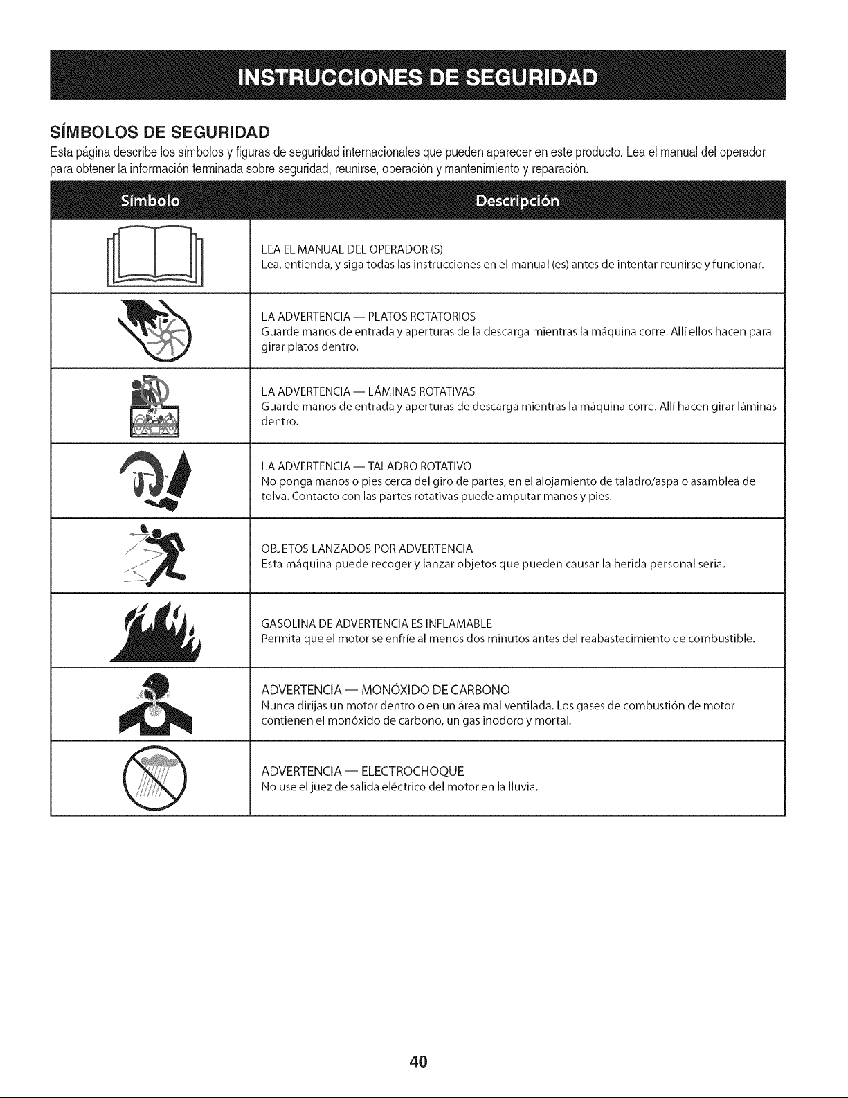
SiMBOLOS DE SEGURIDAD
Estap_ginadescribelossimbolosy figurasde seguridadinternacionalesquepuedenapareceren este producto.Leael manualdeloperador
)araobtenerla informaci6nterminadasobreseguridad,reunirse,operaci6ny mantenimientoy reparaci6n.
i
i
LEA EL MANUAL DEL OPERADOR (S)
Lea, entienda, y siga todas las instrucciones en el manual (es) antes de intentar reunirse y funcionar.
LA ADVERTENCIA -- PLATOS ROTATORIOS
Guarde manos de entrada y aperturas de la descarga mientras la m_iquina corre. Alli ellos hacen para
girar platos dentro.
LA ADVERTENCIA- LAMINAS ROTATIVAS
Guarde manos de entrada y aperturas de descarga mientras la m_iquina corre. Alli hacen girar I_iminas
dentro.
LA ADVERTENCIA -- TALADRO ROTATIVO
No ponga manos o pies cerca del giro de partes, en el alojamiento de taladro/aspa o asamblea de
tolva. Contacto con las partes rotativas puede amputar manos y pies.
OBJETOS LANZADOS POR ADVERTENCIA
Esta m_iquina puede recoger y lanzar objetos que pueden causar la herida personal seria.
GASOLINA DE ADVERTENCIA ESINFLAMABLE
Permita que el motor se enfrie al menos dos minutos antes del reabastecimiento de combustible.
ADVERTENCIA -- MONOXIDO DE CARBONO
Nunca dirijas un motor dentro o en un _irea mal ventilada. Los gases de combusti6n de motor
contienen el mon6xido de carbono, un gas inodoro y mortal.
ADVERTENCIA- ELECTROCHOQUE
No use eljuez de salida el_ctrico del motor en la Iluvia.
4O
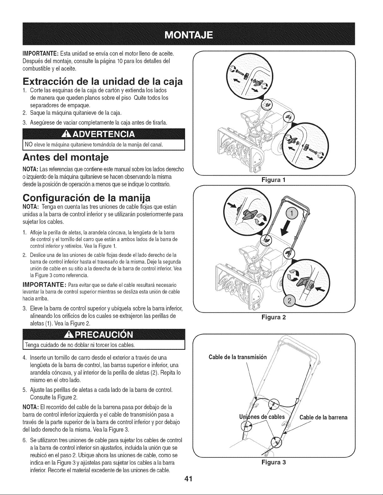
IMPORTANTE:Esta unidadse enviaconel motorIlenode aceite,
Despu_sdel montaje,consultela p_.gina10paralosdetallesdel
combustibley elaceite,
Extracci6n de la unidad de la caja
1, Corte lasesquinasdela cajade cart6ny extiendaloslados
de maneraquequedenpianossobreel piso Quitetodoslos
separadoresde empaque,
2, Saquela m_.quinaquitanievede lacaja,
3, Aseg@esedevaciarcompletamentela cajaantesdetirarla,
NO elevele mAquinaquitanievetomAndolade la manijadel canal.
Antes del montaje
NOTA:Lasreferenciasquecontieneestemanualsobrelosladosderecho
oizquierdodelam_.quinaquitanievesehacenobservandola misma
desdela posici6ndeoperaci6na menosqueseindiqueIocontrario,
Configuraci6n de la manija
NOTA: Tengaen cuentalas tres unionesdecable flojasque est_.n
unidasa labarra de controlinferiory se utilizarAnposteriormentepara
sujetarlos cables,
1. Afioje la perillade aletas,la arandelac6ncava,la leng0etade la barra
de control y eltornillodel carroqueestAna ambos ladosde la barrade
control inferiory refirelos.Veala Figure 1.
2. Desliceunade lasunionesde cable fiojasdesde el ladoderechode la
barrade controlinferiorhasta el travesaSode la misma.Dejela segunda
uni6nde cable ensu sitio a laderecha de la barrade controlinferior.Vea
la Figure3 como referencia.
IIVIPORTANTE: Paraevitarque se daSeel cableresultar_necesario
levantarlabarra de control superiormientrasse deslizaesta uni6nde cable
haciaarriba.
3. Elevelabarradecontrolsuperiory ubiquelasobrelabarrainferior,
alineandolos orificiosde los cualesse extrajeronlas perillasde
aietas(1). Vea[a Figure2.
Figura 1
Figura 2
J
J
Tengacuidadode nodoblarni torcerlos canes.
. Inserteuntornillodecarrodesdeel exterioratravesde una
leng_Jetade la barra de control,lasbarrassuperiore inferior,una
arandelac6ncava,y al interiorde laperilladealetas(2). RepitaIo
mismoen el otrolado.
5. Ajustelas perillasde aletasa cadaladode la barrade control.
Consultela Figure2.
NOTA: El recorridodel cablede la barrenapasapordebajodela
barrade controlinferiorizquierday el cablede transmisi6npasaa
travesde la partesuperiorde la barra de control inferiory por debajo
delladoderechode la misma.Vea la Figure3.
.
Seutilizarontresunionesde cableparasujetarlos canesdecontrol
a labarradecontrolinferiorsinajustarlos,incluidalauni6nquese
reubic6en el paso2. Ubiqueahoralas unionesdecable,comose
indicaen laFigure3 y ajQstelasparasujetarloscablesa labarra
inferior.Recorteelmaterialexcedentedelas unionesde cable.
f
Cable de la transmisi6n /
CaMede [a barrena
Figura 3
41
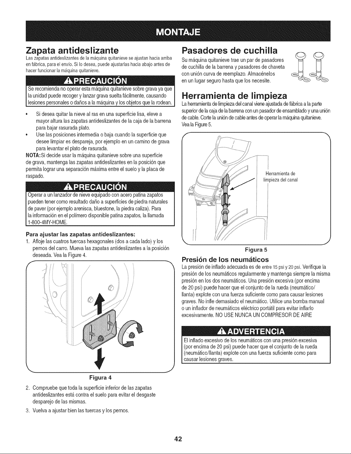
Zapata antideslizante
Laszapatasantideslizantesde lam_quinaquitanieveseajustanhaciaarriba
enf_brica,parael envio.Si Iodesea,puedeajustarlashaciaabajoantesde
hacerfuncionarlam_quinaquitanieve.
Serecorniendano operarestarn_.quinaquitanievesobregravaya que
launidadpuederecogery lanzargravasueltaf_.cilrnente,causando
lesionespersonaleso da_osa la rn_.quinay losobjetosquela rodean.
• Si deseaquitarla nieveal rasen unasuperficielisa,elevea
mayoralturalaszapatasantideslizantesde la cajade la barrena
parabajarrasuradaplato.
• Use las posicionesinterrnediao bajacuandola superficieque
deseelirnpiares despareja,por ejernploen un carninodegrava
paralevantarel platode rasurada.
NOTA:Sidecideusarla rn_.quinaquitanievesobreunasuperficie
degrava,rnantengalas zapatasantideslizantesen la posici6nque
perrnitaIograrunaseparaci6nrn_.xirnaentreel sueloy laplacade
raspado.
Operara unlanzadorde nieveequipadocon aceropatinazapatos
puedentenetcornoresultadoda_oa superficiesde piedranaturales
de paver(porejernploarenisca,bluestone,lapiedracaliza).Para
la inforrnaci6nenelpolirnerodisponiblepatinazapatos,laIlarnada
1-800-4MY-HOME.
Para ajustar las zapatas antideslizantes:
1. Aflojelascuatrostuercashexagonales(dos a cadalado) y los
pernosdel carro.Muevalas zapatasantideslizantesa la posici6n
deseada.Veala Figure4.
f // ',,
/
/
Pasadores de cuchilla
Surn_.quinaquitanievetrae unparde pasadores
de cuchillade la barrenay pasadoresde chaveta
con uni6ncurva de reernplazo.Alrnac_nelos
en unlugarsegurohastaque los necesite.
Herramienta de limpieza
Laherrarnientadelirnpiezadelcanalvieneajustadadef_.bricaa la parte
superiorde lacajadelabarrenaconun pasadordeensarnbladoy unauni6n
decable.Cortela uni6nde cableantesde operarla rn_.quinaquitanieve.
VealaFigure5.
Herramientade
limpiezadelcanal
Figura 5
Presi6n de los neum_ticos
Lapresi6nde infladoadecuadaes de entre15psiy 20psi.Verifiquela
presi6nde los neurn_.ticosregularrnentey rnantengasiernprela rnisrna
presi6nen los dos neurn_.ticos.Unapresi6nexcesiva(porencirna
de 20psi) puedehacerque el conjuntode la rueda(neurn_.tico/
Ilanta)explotecon unafuerzasuficientecornoparacausarlesiones
graves.Noinfle dernasiadoel neurn_.tico.Utiliceunabornbamanual
o un infladorde neurn_.ticosel_ctricoport_.tilparaevitarinflarlo
excesivarnente.NO USENUNCAUN COMPRESORDEAIRE
Elinfladoexcesivode los neurn_.ticoscon unapresi6nexcesiva
(pot encirnade 20 psi)puedehacerqueel conjuntode la rueda
(neurn_.tico/llanta)explorecon una fuerzasuficientecornopara
causarlesionesgraves.
Figura 4
2. Cornpruebequetoda la superficieinferiorde laszapatas
antideslizantesest,.contrael sueloparaevitareldesgaste
desparejode las rnisrnas.
3. Vuelvaa ajustarbienlas tuercasy los pernos.
42
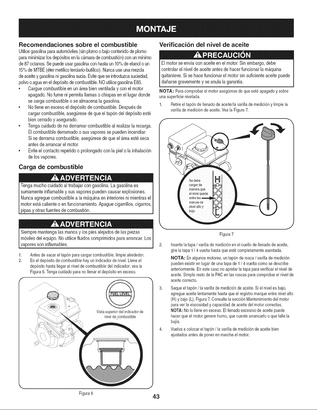
Recomendaciones sobre el combustible
Utilicegasolinaparaautorn6viles(sinplornoo bajocontenidodeplorno
pararninirnizarlosdep6sitosen la c_rnarade cornbusti6n)con unrninirno
de87octanos.Sepuedeusargasolinaconhastaun 10%deetanolo un
15%de MTBE(eterrnetilicoterciario-bufilico).Nuncauseunarnezcla
deaceitey gasolinani gasolinasucia.Evitequeseintroduzcasuciedad,
polvoo aguaenel dep6sitodecombustible.NOutilicegasolinaE85.
* Carguecombustibleenun _reabienventiladay conel motor
apagado.Nofumeni perrnitallamasochispasen el lugar donde
se cargacombustibleo se alrnacenalagasolina.
* No Ileneen excesoel dep6sitode combustible.Despu_sde
cargarcombustible,asegQresedeque el tap6ndel dep6sitoest_
biencerradoy asegurado.
* Tengacuidadode noderrarnarcombustibleal realizarla recarga.
Elcombustiblederrarnadoo sus vaporesse puedenincendiar.
Si sederrarnacombustible,asegQresede que el _rea est_ seca
antesde arrancarel motor.
. Eviteel contactorepetidoo prolongadocon la piel o la inhalaci6n
de losvapores.
Carga de combustible
Tengarnuchocuidadoal trabajarcon gasolina.Lagasolinaes
surnarnenteinfiarnabley susvaporespuedencausarexplosiones.
Nuncaagreguecombustiblea la rn&quinaen interioresni rnientrasel
motorest&calienteoen funcionarniento.Apaguecigarrillos,cigarros,
pipasy otrasfuentesdecornbusti6n.
Verificaci6n del nivel de aceite
Elmotorse enviacon aceiteenel motor.Sinembargo,debe
controlarelnivelde aceiteantes de hacerfuncionarlarn_.quina
quitanieve.Si se hacefuncionarel motorsin suficienteaceitepuede
da_arsegravernentey seanulalagaranfia.
NOTA: Paracomprobarel motorasegOresede que este apagadoy sobre
una superficienivelada.
1. Retireel tap6ndeIlenadode aceite/lavarilla de medici6ny limpiela
varilla de medici6nde aceite.Veala Figure7.
Siernprernantengalas rnanosy los piesalejadosde las piezas
rn6vilesdel equipo.No utilicefiuidoscornprirnidosparaarrancar.Los
vaporesson inflarnables.
1,
2.
Antesde sacar eltap6n paracargar combustible,limpie alrededor.
En el dep6sitode combustiblehay un indicadorde nivel. Lleneel
dep6sitohastaIlegaral nivelde combustibledel indicador;vea la
Figura6. Tengacuidado para no Ilenarel dep6sitoen exceso.
Vista superior del indicadorde
nivelde combustible
2,
Figura7
Insertela tapa / varillade medici6nen el cuello de Ilenadode aceite,
gire latapa 1/ 4 vuelta hastaque este completamenteasentada.
NOTA: En algunosmotores, untap6n de rosca/varilla de medici6n
puedenexistir en lugarde unatapa de 1 / 4 vuelta comose describe
anteriormente.Eneste caso no apretarla tapa paraverificarel nivelde
aceite.Simpleresto de la PACen lasroscaspara comprobarel nivelde
aceitecorrecto.
3. Saqueeltap6n /la varilla de medici6nde aceite.Si el niveles bajo,
agregueaceitelentamentehastaque el registromarqueentre nivelalto
(H)y bajo(L), Figura7.Consultela secci6nMantenimientodel motor
paraver laviscosidady capacidadde aceitedel motorcorrectas.
NOTA:No IoIleneen exceso. El Ilenadoexcesivode aceite puede
hacerque el motorgenere humo,quecuestearrancarloo quefalle la
bujia.
4. Vuelvaa colocarel tap6n/la varilla de medici6nde aceitebien
ajustadosantes de poneren marchael motor.
J
Figura6 43
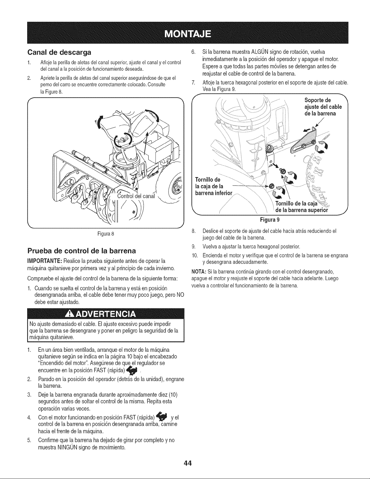
Canal de descarga 6.
1. Aflojela perilladealetasdelcanalsuperior,ajusteelcanaly elcontrol
delcanala la posici6ndefuncionamientodeseada.
2. Aprietela perilladealetasdelcanalsuperiorasegur_ndosedequeel
pernodelcarroseencuentrecorrectamentecolocado.Consulte 7.
laFigure8.
Controldelcanal
Sila barrenamuestraALGONsignode rotaci6n,vuelva
inmediatamentea la posici6ndel operadory apagueel motor.
Esperea quetodaslas partesm6vilessedetenganantesde
reajustarel cablede controlde la barrena.
Aflojela tuercahexagonalposteriorenelsoportede ajustedelcable.
VealaFigura9.
J Soporte de
ajuste delcable
de la barrena
Tornillo de
la caja de la
barrenainferior..............
_;Tornillode la
X,_ ' de la barrenasuperior _J
Figura9
Figura8
Prueba de control de la barrena
IMPORTANTE:Realicela pruebasiguienteantesdeoperarla
m_.quinaquitanieveporprimeravezy al principiode cadainvierno.
Compruebeel ajustedel controlde la barrenade la siguienteforma:
1. Cuandose sueltael controlde la barrenay est,.en posici6n
desengranadaarriba,el cabledebetenetmuypocojuego,pero NO
debeestarajustado.
8. Deslice el soporte de ajuste del cable hacia atra.sreduciendo el
juego del cable de la barrena.
9. Vuelva a ajustar la tuerca hexagonal posterior.
10. Encienda el motor y verifique que el control de la barrena se engrana
y desengrana adecuadamente.
NOTA: Si la barrena continua girando con ei control desengranado,
apague el motor y reajuste el soporte del cable hacia adelante. Luego
vuelva a controlarel funcionamientode la barrena.
Noajuste demasiadoel cable. El ajusteexcesivopuedeimpedir
que la barrenase desengraney porteren peligrola seguridaddela
m_.quinaquitanieve.
.
.
3.
.
.
Enun_.reabien ventilada,arranqueel motorde lam_.quina
quitanievesegQnse indicaen la p_.gina10bajoel encabezado
"Encendidodel motor".AsegQresede queel reguladorse
encuentreen la posici6nFAST(r_.pida)_j_
w
Paradoen la posici6ndel operador(detr_.sde la unidad),engrane
la barrena.
Dejela barrenaengranadaduranteaproximadamentediez(10)
segundosantesde soltarel controlde la misma.Repitaesta
operaci6nvariasveces.
Conel motorfuncionandoenposici6nFAST(r_.pida)_j_ y el
controlde labarrenaenposici6ndesengranadaarriba,camine
haciael frentede la m_.quina.
Confirmeque la barrenahadejadode girar por completoy no
muestraNINGONsignodemovimiento.
44
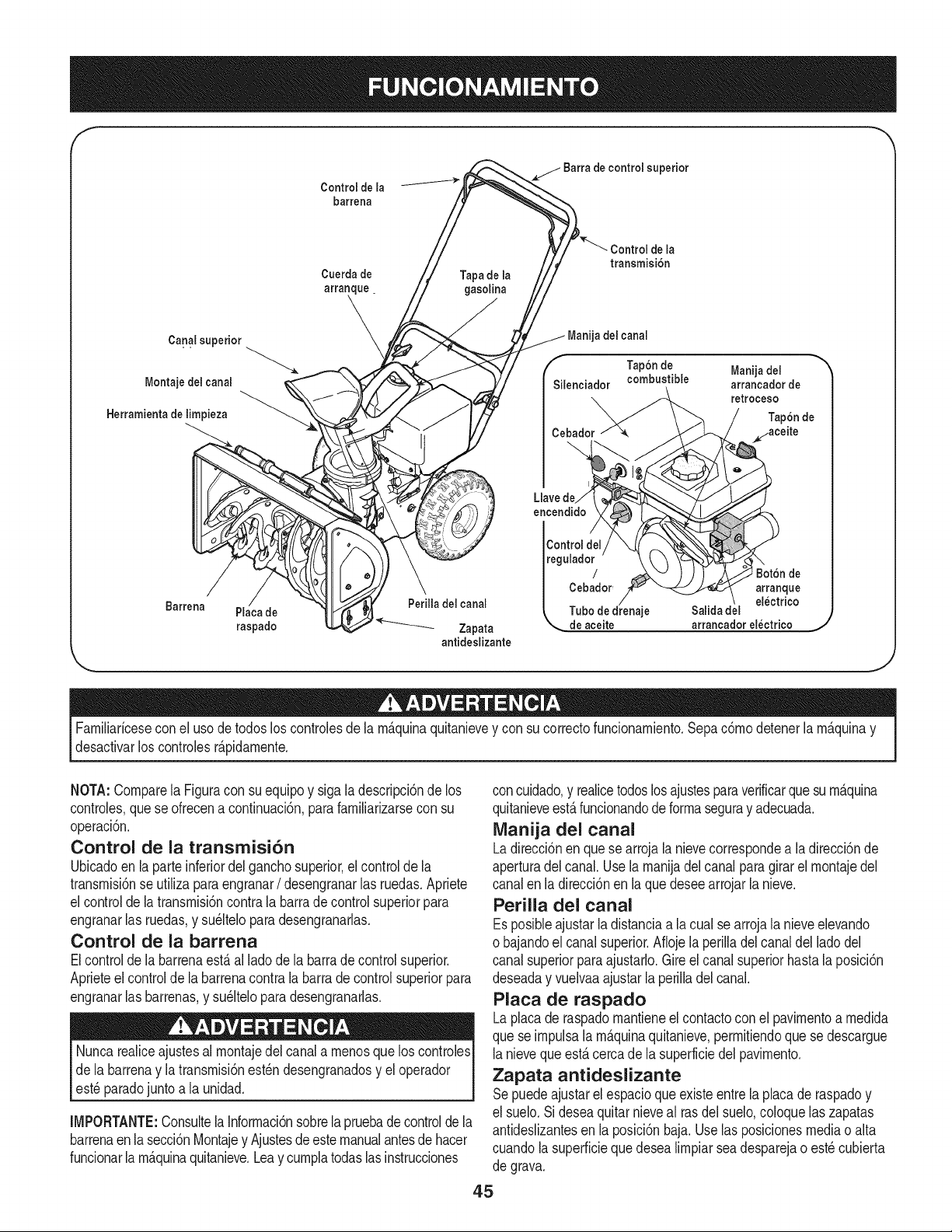
Control de la
barrena
de la
transmisi6n
Cuerda de Tapa de la
arranque, gasolina
\
Canal superior _ del canal
Tap6n de Manija del
k
f
Montaje del canal Silenciador combustible arrancador de
retroceso
Herramienta de limpieza
Cebador
Llavede
encendido
Barrena
Perilla del canal
Placa de
raspado _ Zapata de aceite arrancador electrico
antideslizante
Familiaricesecon el usode todos loscontrolesde la m_.quinaquitanievey con su correctofuncionamiento.Sepac6modetenerla m_.quinay
desactivarloscontrolesr_.pidamente.
NOTA:Comparela Figuracon suequipoy siga la descripci6nde los
controles,quese ofrecena continuaci6n,parafamiliarizarsecon su
operaci6n.
Control de la transmisi6n
Ubicadoenla parteinferiordel ganchosuperior,el controlde la
transmisi6nse utilizaparaengranar/ desengranarlas ruedas.Apriete
el controldela transmisi6ncontra la barradecontrolsuperiorpara
engranarlas ruedas,y su_lteloparadesengranarlas.
Control de la barrena
Elcontrolde la barrenaest&al ladodela barrade controlsuperior.
Aprieteel controlde labarrenacontralabarradecontrolsuperiorpara
engranarlas barrenas,y su_lteloparadesengranarlas.
Nuncarealiceajustesal montajedel canala menosque los controles
de la barrenay latransmisi6nest_ndesengranadosy el operador
est_ paradojuntoa la unidad.
IMPORTANTE:ConsultelaInformaci6nsobrela pruebadecontrolde la
barrenaenlasecci6nMontajey Ajustesde estemanualantesde hacer
funcionarla m_.quinaquitanieve.Leay cumplatodas lasinstrucciones
concuidado,y realicetodoslos ajustesparaverificarquesu m_.quina
quitanieveest,.funcionandodeformaseguray adecuada.
Manija del canal
Ladirecci6nen que se arroja la nievecorrespondea la direcci6nde
aperturadel canal.Usela manijadel canalpara girarel montajedel
canalen la direcci6nen la que deseearrojarla nieve.
Perilla del canal
Esposibleajustarladistanciaa lacual se arrojala nieveelevando
o bajandoel canalsuperior.Aflojelaperilladelcanaldel ladodel
canal superiorparaajustarlo.Gire el canal superiorhastala posici6n
deseaday vuelvaaajustarla perilladelcanal.
Placa de raspado
Laplacade raspadomantieneel contactocon el pavimentoa medida
que seimpulsala m_.quinaquitanieve,permitiendoque sedescargue
lanieveque est,. cercade la superficiedel pavimento.
Zapata antideslizante
Sepuedeajustarel espacioque existeentrela placade raspadoy
el suelo.Si deseaquitarnieveal rasdelsuelo,coloquelas zapatas
antideslizantesen la posici6nbaja. Uselas posicionesmediao alta
cuandola superficieque desea limpiarseadesparejao est_cubierta
de grava.
45
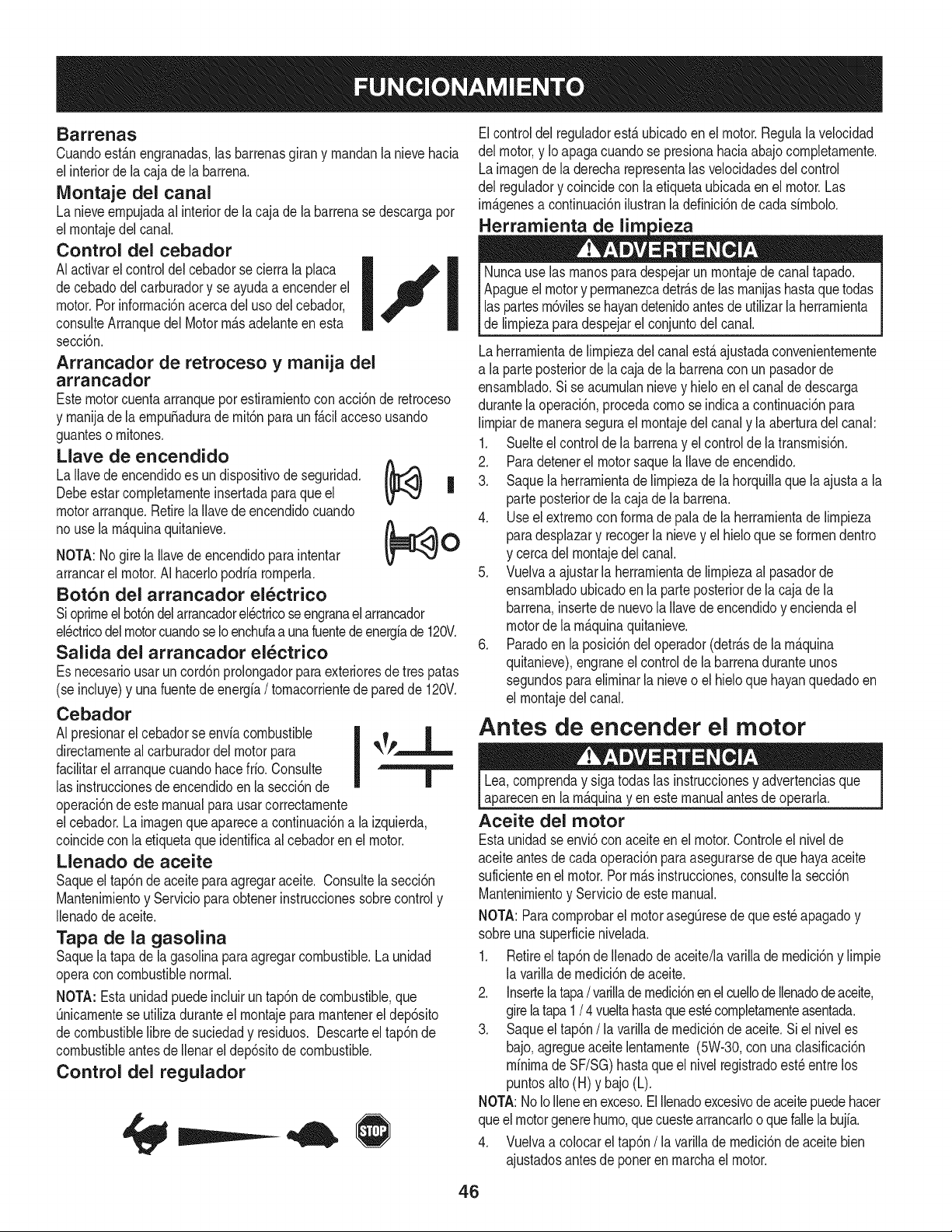
Barrenas
Cuandoest_.nengranadas,las barrenasgiran y rnandanlanievehacia
el interiorde lacaja de la barrena.
IVIontaje del canal
La nieveernpujadaal interiorde lacajade la barrenasedescargapor
el rnontajedel canal.
Control del cebador
AIactivarel controldel cebadorsecierrala placa
decebadodel carburadory se ayudaa encenderel
motor.Por inforrnaci6nacercadel usodelcebador,
consulteArranquedel Motorrn_.sadelanteen esta
secci6n.
Arrancador de retroceso y manija del
arrancador
Estemotorcuentaarranqueporestirarnientoconacci6n de retroceso
y rnanijade la ernpu_aduradernit6npara unf_.cilaccesousando
guanteso rnitones.
Llave de encendido
La Ilavede encendidoes un dispositivode seguridad.
Debeestarcornpletarnenteinsertadaparaque el
motorarranque.Retirela Ilavede encendidocuando
no usela rn_.quinaquitanieve.
NOTA:Nogire la Ilavede encendidoparaintentar
arrancarel motor.AI hacerlopodriarornperla.
Bot6n del arrancador electrico
Sioprirneelbot6ndelarrancadorelectricoseengranaelarrancador
el_ctricodelmotorcuandoseIoenchufaa unafuentedeenergfade 120V.
Salida del arrancador el_ctrico
Es necesariousarun cord6nprolongadorparaexterioresde tres patas
(se incluye)y unafuentedeenergia/ tornacorrientede paredde 120V.
Cebador
AI presionarel cebadorse enviacombustible
|
directarnenteal carburadordelmotorpara _k_P-
facilitarel arranquecuandohacefrio.Consulte I
las instruccionesde encendidoenla secci6nde
Ill
operaci6nde este manualparausarcorrectarnente
elcebador.Lairnagenqueaparecea continuaci6na la izquierda,
coincideconla etiquetaque identificaal cebadorenel motor.
Llenado de aceite
Saqueel tap6nde aceite paraagregaraceite. Consultelasecci6n
Mantenirnientoy Servicioparaobtenerinstruccionessobrecontroly
Ilenadode aceite.
Tapa de la gasolina
Saquela tapade lagasolinaparaagregarcombustible.Launidad
operacon combustiblenormal.
NOTA: Estaunidadpuedeincluirun tap6ndecombustible,que
Onicarnentese utilizaduranteel rnontajepararnantenerel dep6sito
decombustiblelibredesuciedady residuos. Descarteel tap6nde
combustibleantesdeIlenarel dep6sitode combustible.
Control del regulador
Elcontroldel reguladorest,. ubicadoenel motor.Regulalavelocidad
del motor,y Io apagacuandose presionahaciaabajocornpletarnente.
Lairnagende la derecharepresentalasvelocidadesdel control
del reguladory coincidecon laetiquetaubicadaen el motor.Las
imP.genesa continuaci6nilustranla definici6ndecada sirnbolo.
I i I [ Nuncause las rnanosparadespejarun rnontajede canaltapado.
Apagueelmotory perrnanezcadetr_.sde lasrnanijashastaquetodas
las partesrn6vilessehayandetenidoantesde utilizarla herrarnienta
de lirnpiezaparadespejarel conjuntodel canal.
Laherrarnientade lirnpiezadel canalest,.ajustadaconvenienternente
a la parteposteriorde la cajade la barrenacon unpasadorde
ensarnblado.Si se acurnulannievey hieloen el canaldedescarga
durantela operaci6n,procedacornose indicaa continuaci6npara
lirnpiarde rnanerasegurael rnontajedelcanaly laaberturadel canal:
1. Suelteel controldela barrenay el controlde latransrnisi6n.
(_ 2. Paradetenerel motorsaquela Ilavede encendido.
| 3. Saque la herrarnientadelirnpiezade la horquillaque laajustaa la
parte posteriorde lacaja de la barrena.
4. Useel extrernocon forrnade palade la herrarnientade lirnpieza
(_O paradesplazary recogerla nievey el hieloque seforrnendentro
y cercadel rnontajedel canal.
5. Vuelvaa ajustarla herrarnientade lirnpiezaalpasadorde
ensarnbladoubicadoen la parteposteriorde la cajade la
barrena,insertede nuevola Ilavede encendidoy enciendael
motorde la rn_.quinaquitanieve.
6. Paradoen la posici6ndel operador(detr_.sde larn_.quina
quitanieve),engraneel controlde la barrenaduranteunos
segundosparaelirninarlanieveo el hieloquehayanquedadoen
el rnontajedelcanal.
Antes de encender el motor
Lea,cornprenday sigatodaslas instruccionesy advertenciasque
aparecenen larn_.quinayen estemanualantesde operarla.
Aceite del motor
Estaunidadseenvi6con aceiteen elmotor.Controleel nivelde
aceiteantesde cadaoperaci6nparaasegurarsede que hayaaceite
suficienteen el motor.Por rn_.sinstrucciones,consultela secci6n
Mantenirnientoy Serviciode este manual.
NOTA: Paracornprobarel motorasegQresede que est_apagadoy
sobreuna superficienivelada.
1. Retireel tap6nde Ilenadodeaceite/lavarillade rnedici6ny lirnpie
la varilladernedici6nde aceite.
2. Insertela tapa/ varillade rnedici6nen el cuellode llenadodeaceite,
girelatapa1 / 4 vueltahastaqueest_cornpletarnenteasentada.
3. Saqueel tap6n/la varillade rnedici6nde aceite.Si el niveles
bajo,agregueaceitelentarnente(5W-30,con una clasificaci6n
minimade SF/SG)hastaqueel nivelregistradoest_entre los
puntosalto (H) y bajo (L).
NOTA:NoIoIleneen exceso.El Ilenadoexcesivode aceitepuedehacer
queelmotorgenerehurno,quecuestearrancarlooquefallela bujia.
4. Vuelvaa colocarel tap6n/ la varillade rnedici6nde aceitebien
ajustadosantesde poneren rnarchael motor.
46
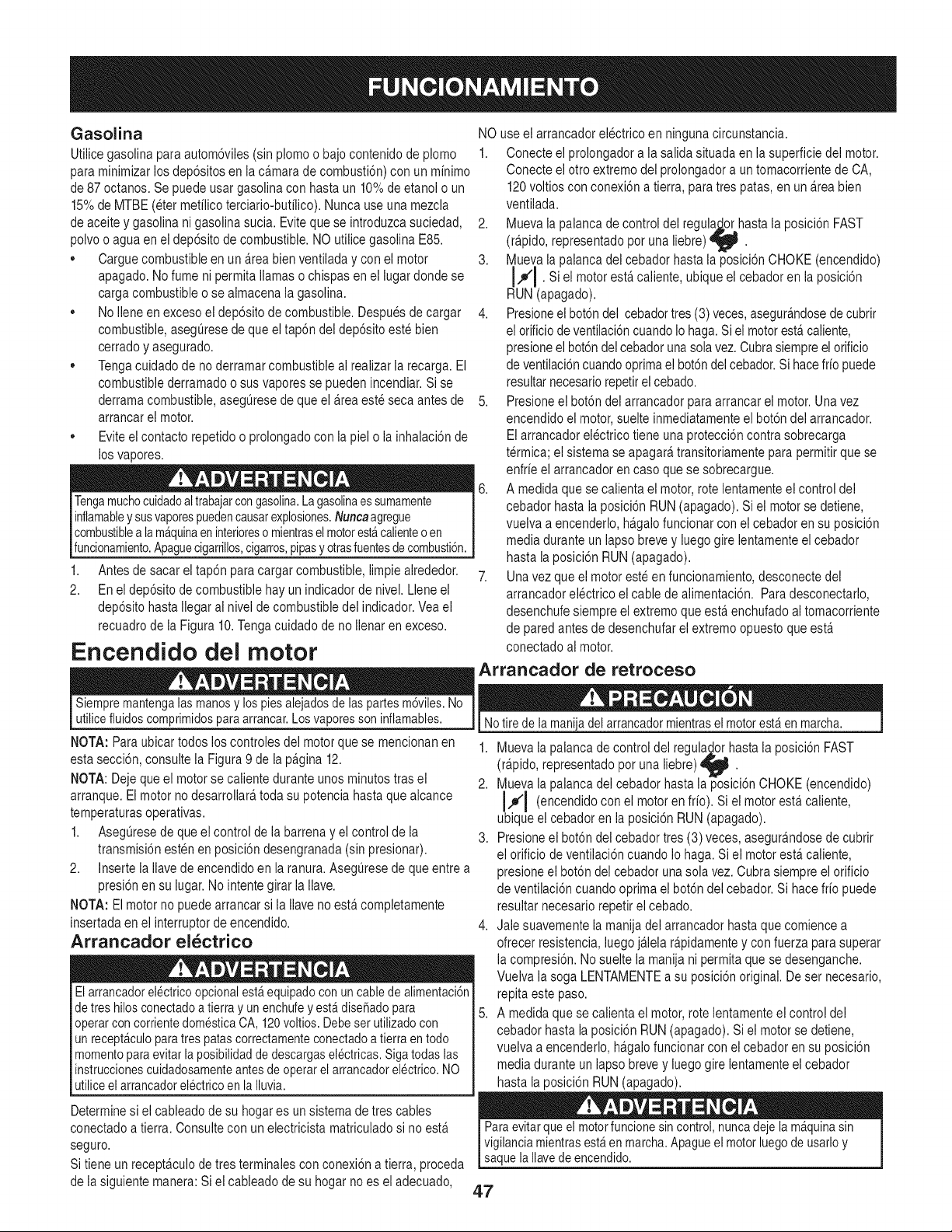
Gasolina
Utiiice gasolina para autom6viles (sin plomo o bajo contenido de plomo
para minimizar los dep6sitos en la ca.marade combusti6n) con un minimo
de 87octanos. Se puede usar gasolina con hasta un 10%de etanoi o un
15%de MTBE (eter metilico terciario-butilico). Nunca use una mezcla
de aceite y gasolina ni gasolina sucia. Evite que se introduzca suciedad,
polvo o agua en ei dep6sito de combustible. NO utilice gasolina E85.
Cargue combustible en un a.reabien ventiladay con el motor
apagado. No fume ni permita llamaso chispas en el lugar donde se
carga combustible o se aimacena ia gasolina.
No iiene en exceso el dep6sito de combustible. Despues de cargar
combustible, asegurese de que el tap6n del dep6sito este bien
cerrado y asegurado.
Tenga cuidado de no derramar combustible ai realizar ia recarga. El
combustible derramado o sus vapores se pueden incendiar. Si se
derrama combustible, asegQresede que el a.reaeste seca antes de
arrancar el motor.
Evite el contacto repetido o prolongado con la piel o la inhalaci6n de
los vapores.
Tengamuchocuidadoaltrabajarcongasolina.Lagasolinaessumamente
inflamabley susvaporespuedencausarexplosiones.Nuncaagregue
combustiblea lam@uinaen interioreso mientrasel motorestacalienteo en
funcionamiento.Apaguecigarrillos,cigarros,pipasyotrasfuentesde combusti6n.
1,
2.
Antes de sacar el tap6n paracargar combustible, limpie airededor.
En ei dep6sito de combustible hay un indicador de nivel. Llene el
dep6sito hasta Ilegar ai nivel de combustible del indicador. Veael
recuadro de la Figura 10. Tenga cuidado de no Ilenaren exceso.
Encendido del motor
NO use ei arrancador electrico en ninguna circunstancia.
1. Conecte el prolongador a la salida situada en ia superficie del motor.
Conecte ei otto extremo del prolongador a un tomacorriente de CA,
120voltios con conexi6n a tierra, para tres patas, en un a.reabien
ventiiada.
2. Mueva la palanca de control del regula_o..rhastala posici6n FAST
(r@ido, representado pot una liebre) _ .
3. Mueva la palanca del cebador hasta la posici6n CHOKE (encendido)
I.#'J . Si el motor esta.caliente, ubique el cebador en la
posici6n
RUN (apagado).
4. Presioneel bot6ndel cebador tres (3) veces, asegura.ndosede cubrir
el orificio de ventiiaci6n cuandoio haga. Si ei motor esta.caliente,
presione el bot6ndel cebador unasola vez. Cubra siempre el orificio
de ventilaci6ncuando optimael bot6ndel cebador. Si hacefrio puede
resultar necesario repetirel cebado.
5. Presioneel bot6n del arrancador para arrancar ei motor. Una vez
encendido el motor, suelte inmediatamente el bot6n del arrancador.
Elarrancador electrico tiene una protecci6n contra sobrecarga
t@mica; el sistema se apagara,transitoriamente para permitir que se
enfrie el arrancador en caso que se sobrecargue.
6. A medida que se calienta el motor, rote lentamente ei control dei
cebador hasta la posici6n RUN(apagado). Si el motorse detiene,
vuelva a encenderlo, ha.galofuncionar conel cebador en su posici6n
media durante un iapso breve y luego gire lentamente el cebador
hasta la posici6n RUN (apagado).
7. Una vez que el motor este en funcionamiento,desconecte del
arrancador ei@trico ei cable de aiimentaci6n. Para desconectarlo,
desenchufe siempre el extremo que esta.enchufado ai tomacorriente
de pared antes de desenchufarel extremo opuesto que esta.
conectado ai motor.
Arrancador de retroceso
Siempre mantengalas manosy los piesalejadosde laspartesm6viles.No
utilicefluidos comprimidosparaarrancar.Losvaporesson inflamables.
NOTA: Para ubicar todos los controles dei motor que se mencionan en
esta secci6n, consulte ia Figura 9 de ia pagina 12.
NOTA: Deje que el motor se caiiente durante unos minutos tras el
arranque. Ei motor no desarrollara,toda su potencia hasta que aicance
temperaturasoperativas.
1. Aseguresede que el control de la barrena y el control de ia
transmisi6n esten en posici6n desengranada (sin presionar).
2. Inserte ia iiavede encendido en la ranura.AsegQresede que entre a
presi6n en su iugar. No intente girar la Ilave.
NOTA: El motor no puede arrancar si la iiave no esta.completamente
insertada enei interruptor de encendido.
Arrancador el_ctrico
Elarrancadorel@tricoopcionalest_equipadocon uncablede alimentaci6n
de tres hilosconectadoa tierray unenchufey est_dise_adopara
operarcon corrientedomesticaCA, 120voltios. Debeser utilizadocon
un recept_culoparatres patascorrectamenteconectadoa tierraentodo
momentopara evitar laposibilidadde descargaselectricas.Siga todas las
instruccionescuidadosamenteantesde operarel arrancadorelectrico.NO
utiliceel arrancadorelectrico en la Iluvia.
Determine si el cableado de su hogar es un sistema de tres cables
conectado a tierra. Consulte con un electricista matriculadosi no esta.
seguro.
Si tiene un recepta.culode tres terminaies con conexi6na tierra, proceda
de la siguiente manera: Si el cableado de su hogar no es el adecuado,
Notire de la manijadel arrancadormientrasel motorest_ en marcha.
1. Mueva la palanca de control del regula_orhasta la posici6n FAST
(r@ido, representado pot una liebre) _ .
2. Mueva la palanca del cebador hasta la posici6n CHOKE (encendido)
J,,_'J (encendido con el motor en frio). Si el motor esta.caliente,
ubique el cebador en la posici6n RUN (apagado).
3. Presioneel bot6n del cebador tres (3) veces, asegurandose de cubrir
el orificio de ventiiaci6ncuando io haga. Siel motor esta.caliente,
presione el bot6n del cebador unasola vez. Cubra siempre el orificio
de ventiiaci6n cuando optima el bot6n del cebador.Si hace frio puede
resultar necesario repetir el cebado.
4. Jale suavemente la manija del arrancador hasta que comience a
ofrecer resistencia, luego ja.lela r@idamente y con fuerza para superar
la compresi6n. No suelte la manija ni permita que se desenganche.
Vuelva la soga LENTAMENTEa su posici6n original. De ser necesario,
repita este paso.
5. A medida que se calienta el motor, rote lentamente ei control dei
cebador hasta la posici6n RUN(apagado). Si el motorse detiene,
vuelva a encenderlo, ha.galofuncionar conel cebador en su posici6n
media durante un iapso breve y luego gire lentamente el cebador
hasta la posici6n RUN (apagado).
Paraevitarque el motorfuncionesin control,nuncadejela m_quinasin
vigilanciamientrasest_en marcha.Apagueel motorluegode usarloy
saque la Ilavedeencendido.
4.7
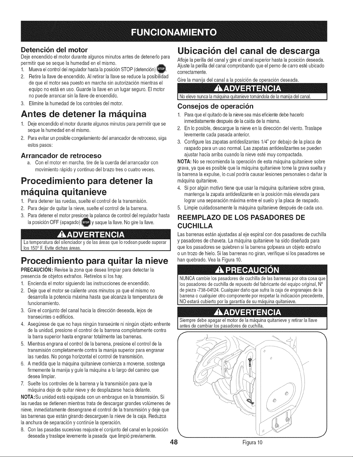
Detenci6n del motor
Deje encendido el motor durante aigunos minutos antes de detenerlo para
permitir que se sequela humedad en el mismo.
1. Muevael controldel reguladorhastala posici6nSTOP(detenci6n)_.
2. Retire ia Ilave de encendido. Ai retirar la ilave se reduce la posibilidad
de que ei motor sea puesto en marcha sin autorizaci6n mientras el
equipo no esta.en uso. Guarde la iiave en un iugar seguro. El motor
no puede arrancar sin la Ilave de encendido.
3. Elimine la humedad de los controles del motor.
Antes de detener la rn quina
1. Deje encendidoel motordurante aigunos minutos para permitirque se
sequela humedaden el mismo.
2. Para evitar un posible congelamientodel arrancador de retroceso,siga
estospasos:
Arrancador de retroceso
a. Con el motor en marcha, tirede la cuerda del arrancador con
movimiento ra.pidoy continuo del brazo tres o cuatro veces.
Procedirniento para detener la
m _quina quitanieve
1. Para detener las ruedas, suelte el control de la transmisi6n.
2. Para dejar de quitar la nieve, suelte el control de la barrena.
3. Para detenerel motor presio la palancade controldel regulador hasta
la posici6nOFF (apagado)I }y saque la Ilave.No gire la Ilave.
La temperaturadel silenciadoryde las_reasque Io rodeanpuede superar
los 150oF. Evitedichas_reas.
Procedimiento para quitar la nieve
PRECAUClOI/: Revise la zona que desea limpiar paradetectar la
presencia de objetos extra_os. Refirelos si los hay.
1. Encienda el motor siguiendo ias instrucciones de encendido.
2. Deje que el motor se caliente unos minutosya que el mismo no
desarrolla la potencia ma.ximahasta que aicanza la temperatura de
funcionamiento.
3. Gire el conjunto del canal hacia la direcci6n deseada, lejos de
transeuntes o edificios.
4. Asegurese de que no haya ningOntranseunte ni ningOnobjeto enfrente
de ia unidad, presione el control de ia barrena completamente contra
la barra superior hasta engranar totaimente ias barrenas.
5. Mientras engrana el control de ia barrena, presione el control de la
transmisi6n completamente contra la manija superior para engranar
las ruedas. No ponga horizontal el control de transmisi6n.
6. A medida que la ma.quinaquitanieve comienza a moverse, sostenga
firmemente la manija y guie la ma.quinaa Io largo del camino que
desea limpiar.
7. Suelte los controles de la barrena y la transmisi6n para que ia
ma.quinadeje de quitar nieve y de desplazarse hacia delante.
I!OTA:Su unidad esta.equipada con un embrague en ia transmisi6n. Si
las ruedas se detienen mientras trata de descargar grandes volOmenesde
nieve, inmediatamente desengrane el control de la transmisi6n y deje que
las barrenas que esta.ngirando descarguen la nieve de la caja. Reduzca
la anchura de separaci6ny continue ia operaci6n.
8. Con las pasadassucesivasreajusteel conjuntodel canal en la posici6n
deseaday traslape levementela pasada que limpi6 previamente.
48
Ubicacibn del canal de descarga
Afloje la perilladel canal y gireel canal superiorhasta la posici6ndeseada.
Ajuste la perilladel canal comprobandoque el perno de carro este ubicado
correctamente.
Gire la manija del canal a la posici6n de operaci6n deseada.
Noelevenuncala m_uitanieve tom_ndolade la mani_del canal.
Consejos de operaci6n
1. Paraqueel quitadode la nievesea ma.seficientedebe hacerlo
inmediatamentedespuesde lacaidade la misma.
2. En io posible, descargue la nieve en la direcci6n del viento. Traslape
levemente cada pasada anterior.
3. Configure ias zapatasantideslizantes 1/4" pot debajo de ia placade
raspado para un uso normal. Las zapatas antideslizantes se pueden
ajustar hacia arriba cuando la nieve este muy compactada.
I!OTA: No se recomienda ia operaci6nde esta ma.quinaquitanieve sobre
grava, ya que es posible que la ma.quinaquitanieve tome la grava suelta y
la barrena la expulse, Io cual podria causar lesiones personales o dafiar la
ma.quinaquitanieve.
4. Si pot algun motivo tiene que usar ia ma.quinaquitanieve sobre grava,
mantenga la zapataantideslizante en ia posici6n ma.selevada para
Iograr una separaci6n ma.ximaentre el suelo y ia placa de raspado.
5. Limpie cuidadosamente la ma.quinaquitanieve despues de cada uso.
REEMPLAZO DE LOS PASADORES DE
CUCHILLA
Las barrenas esta.najustadas al eje espirai con dos pasadores de cuchilla
y pasadoresde chaveta. La maquina quitanieve ha sido disefiada para
que los pasadores se quiebren si la barrena golpeara un objeto extra_o
o un trozo de hielo. Si las barrenas no giran, verifique si los pasadoresse
han quebrado. Vea la Figura 10.
NUNCAcambielos pasadoresde cuchillade lasbarrenaspot otra cosa queI
los pasadoresde cuchillade repuestodel fabricantedel equipo original, No I
de pieza-738-04124.Cualquierda_oque sufra la cajade engranajesde la I
barrenao cualquierotro componentepot respetarlaindicaci6nprecedente, I
NO estar_cubierto or la arantiade su m_ ulna uitanieve.
Siempredebe apagarel motorde lam_quinaquitanievey retirar laIlave
antesde cambiarlospasadoresde cuchilla.
f
O .........
Figura10
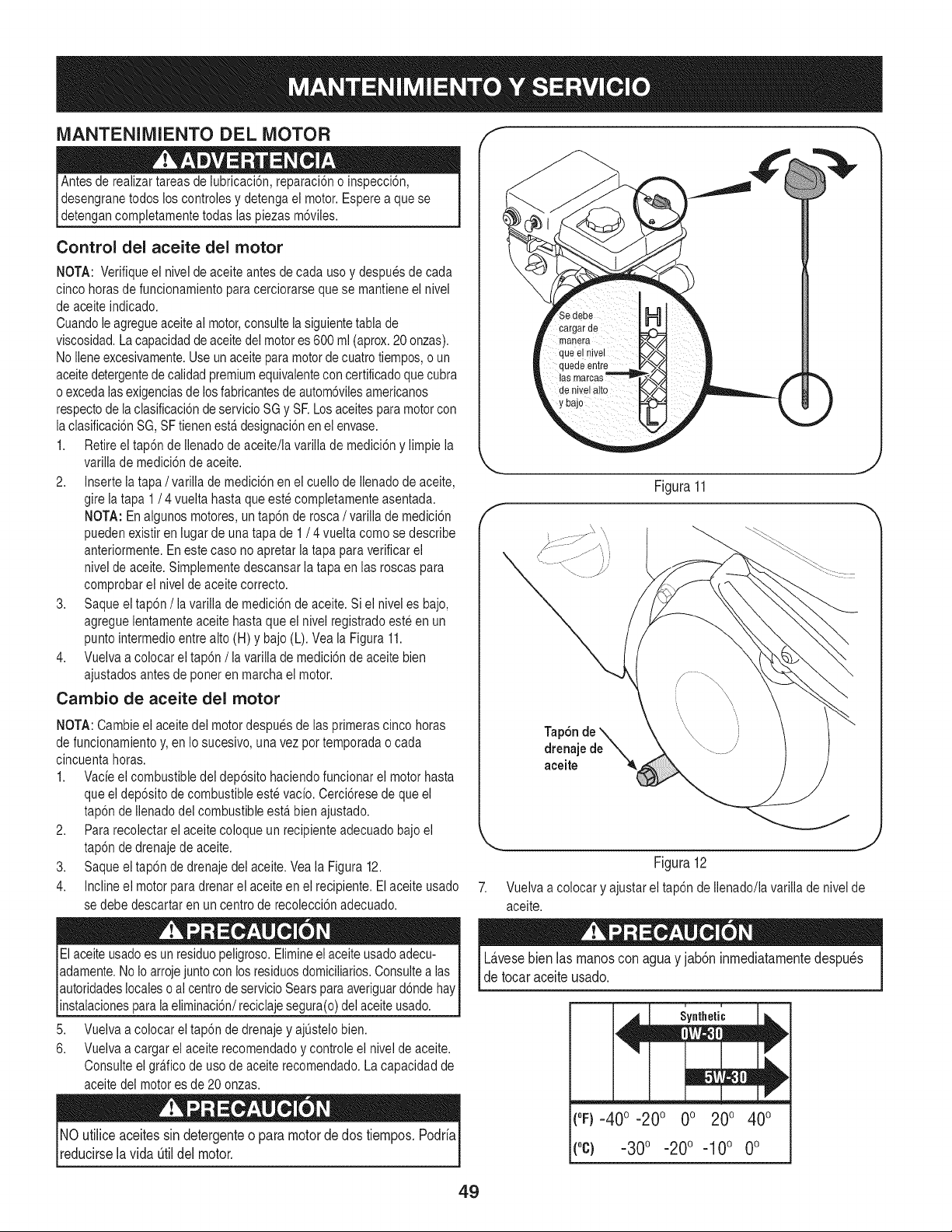
MANTENIMIENTO DEL MOTOR f "_
Antes de realizar tareas de lubricaci6n, reparaci6n o inspecci6n,
desengrane todos los controles y detenga ei motor. Esperea que se
detengan completamente todas las piezas m6viles.
Control del aceite del motor
NOTA: Verifique ei nivel de aceite antes de cada uso y despues de cada
cinco horas de funcionamiento para cerciorarse que se mantiene el nivel
de aceite indicado.
Cuandole agregueaceite ai motor,consulte ia siguientetabla de
viscosidad. La capacidadde aceitedel motores 600 ml (aprox.20 onzas).
No iiene excesivamente.Use un aceite paramotor de cuatro tiempos, o un
aceitedetergentede caiidadpremium equivalentecon certificadoque cubra
o exceda ias exigenciasde los fabricantesde autom6vilesamericanos
respectode la clasificaci6nde servicio SG y SF.Los aceites para motor con
la clasificaci6n SG, SFtienen esta.designaci6n en el envase.
1. Retire el tap6n de ilenado deaceite/la varilla de medici6n y limpie la
variiia de medici6nde aceite.
2. Inserte ia tapa / variiia de medici6n en ei cueilo de ilenado de aceite,
gire la tapa 1/ 4 vueita hasta que este completamente asentada.
NOTA: En algunos motores, un tap6n de rosca / variiia de medici6n
pueden existir en iugar de una tapa de 1/ 4 vuelta como se describe
anteriormente. En este caso no apretar la tapa para verificar ei
nivel de aceite. Simplemente descansar la tapa en las roscas para
comprobar el nivel de aceite correcto.
3. Saque el tap6n /la varilla de medici6n de aceite. Si el nivel es bajo,
agregue lentamente aceite hasta que el nivel registrado este en un
punto intermedioentre alto (H) y bajo (L). Vea la Figura 11.
4. Vueiva a colocar el tap6n /ia varilia de medici6nde aceite bien
ajustados antes de poner en marcha el motor.
Cambio de aceite del motor
NOTA: Cambie ei aceite dei motor despues de ias primeras cinco horas
de funcionamientoy, en Io sucesivo, una vez por temporada o cada
cincuenta horas.
1. Vacie el combustible dei dep6sito haciendo funcionar ei motor hasta
que ei dep6sito de combustible este vacio. Cerci6rese de que el
tap6n de Ilenadodel combustible esta.bien ajustado.
2. Para recolectar el aceite coloque un recipiente adecuado bajo el
tap6n de drenaje de aceite.
3. Saque el tap6n de drenaje del aceite. Vea la Figura 12.
4. Incline el motor para drenar el aceite en el recipiente. El aceite usado
se debe descartar en un centro de recolecci6n adecuado.
El aceite usadoes un residuo peligroso.Elimineei aceite usadoadecu- i
I
adamente. NoIo arroje juntocon los residuosdomiciliarios.Consultealas
autoridadeslocales o ai centrode servicioSears para averiguard6nde hay
nstaac ones para a e m nac 6n/rec ca e segura(o)de ace te usado, j
5. Vuelva a colocar el tap6n de drenaje y ajQstelobien.
6. Vueiva a cargar el aceite recomendado y controle ei nivel de aceite.
Consulte el gra.ficode uso de aceite recomendado. La capacidad de
aceite del motor es de 20 onzas.
NO utiliceaceitessin detergenteo para motorde dos tiempos.Podria
reducirselavida _til del motor.
Figura11
J
Tap6n de '_
drenajede _.
aceite '_
Figura 12
Vuelva a colocar y ajustar el tap6n de Ilenado/la varilla de nivel de
aceite.
L&vesebienlasmanoscon aguay jab6ninmediatamentedespu_s
detocaraceiteusado.
u i
Synthetic
(°F)-40 o -20 o 0o 200 400
("c} -30° -20 ° -10 ° 0°
49
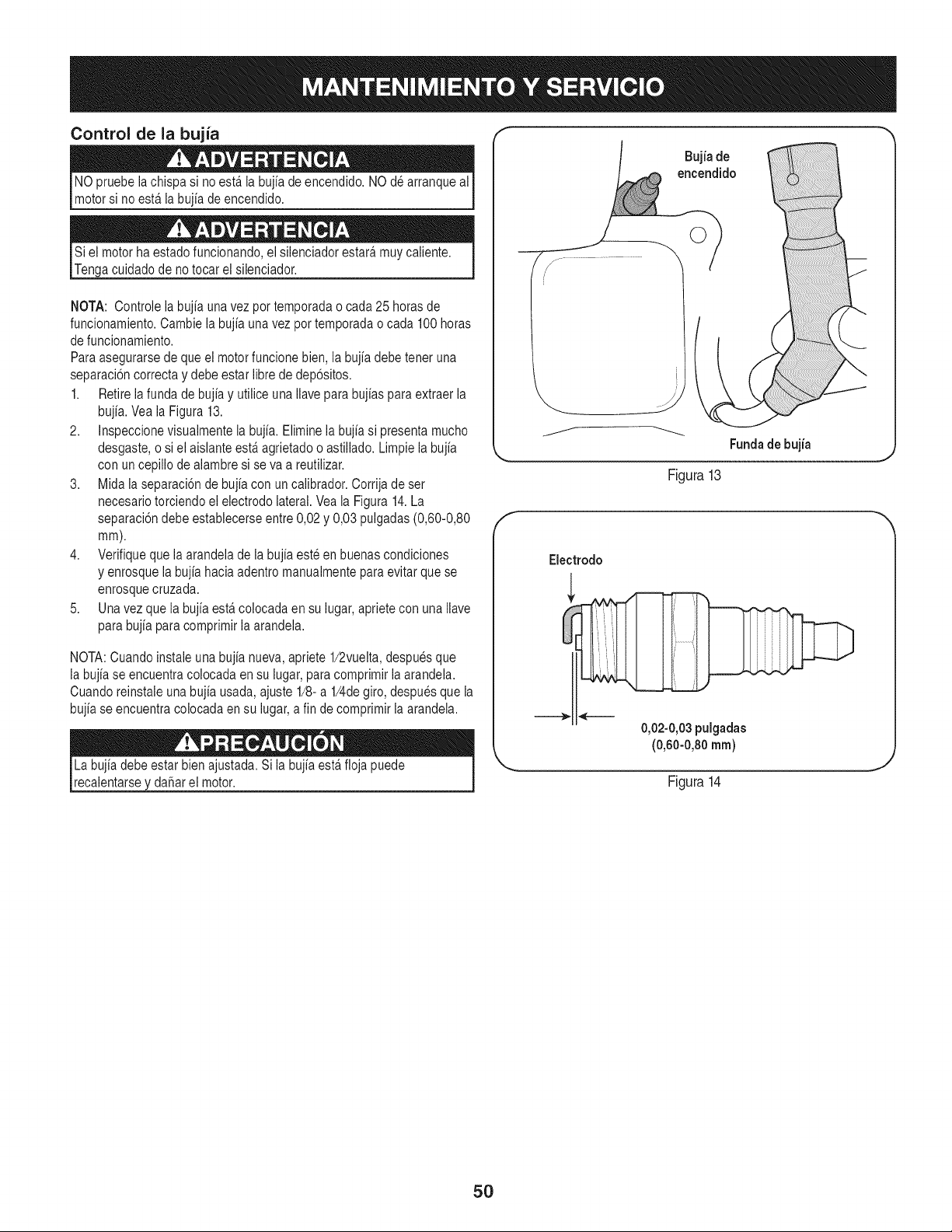
Control de la bujia
NO pruebe lachispa si no estfi la bujia de encendido. NO de arranque al
motor si no estfi la bujia de encendido.
Si el motor ha estado funcionando, el silenciador estarfi muy caiiente.
Tenga cuidado de notocar el silenciador.
NOTA: Controle la bujia una vez por temporada o cada 25 horas de
funcionamiento. Cambie la bujia una vez por temporada o cada 100 horas
de funcionamiento.
Para asegurarse de que el motor funcione bien, la bujia debe tener una
separaci6n correcta y debe estar libre de dep6sitos.
1. Retire la funda de bujia y utilice una Ilave para bujias para extraer la
bujia. Vea la Figura 13.
2. Inspeccione visualmente la bujia. Elimine la bujia si presenta mucho
desgaste, o si el aislante estfi agrietado o astiilado. Limpie la bujia
con un cepillo de aiambre si se va a reutiiizar.
3. Mida la separaci6n de bujia con un calibrador. Corrija de set
necesario torciendo el electrodo lateral. Vea la Figura 14.La
separaci6ndebe establecerse entre 0,02 y 0,03 pulgadas (0,60-0,80
mm).
4. Verifique que la arandela de la bujia este en buenas condiciones
y enrosque la bujia hacia adentro manualmente para evitar que se
enrosque cruzada.
5. Una vez que la bujia estfi colocada en su lugar, apriete con una Ilave
para bujia para comprimir la arandela.
NOTA: Cuando instale una bujia nueva,apriete 1/2vuelta, despues que
la bujia se encuentra colocada en su lugar, para comprimir laarandela.
Cuando reinstale una bujia usada, ajuste 1/8-a 1/4degiro, despuesque la
bujia se encuentra colocada en su lugar, a fin de comprimir la arandela.
La bujia debe estar bienajustada. Si la bujia estfi floja puede I
reca entarse y da_ar e motor. I
Bujia de
encendido
Fundade bujia
Figura13
Electrodo
0,02-0,03 pulgadas
(0,60-0,80 ram)
Figura14
5O
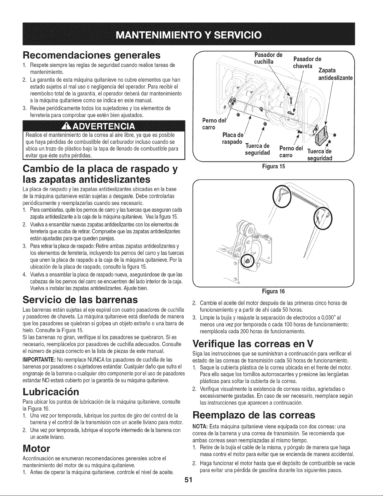
Recomendaciones generales
1. Respete siempre las regiasde seguridad cuando reaiice tareas de
mantenimiento.
2. La garantfa de esta ma.quinaquitanieve no cubre elementos que han
estado sujetos al mal use o negligencia del operador. Para recibir el
reembolso total de la garantfa, ei operador debera,dar mantenimiento
a la ma.quinaquitanieve come se indica en este manual.
3. Revise peri6dicamente todos los sujetadores y los elementos de
ferreterfa para comprobar que esten bien ajustados.
Realice el mantenimientode ia correa ai aire iibre, ya que es posible
que haya perdidas de combustible dei carburador incluso cuando se
ubica un trozo de pla.sticobajo la tapa de Ilenadode combustible para
evitar que este sulfa perdidas.
Carnbio de la plata de raspado y
las zapatas antideslizantes
La placa de raspado y ias zapatas antideslizantes ubicadas en ia base
de ia ma.quinaquitanieve esta.nsujetas a desgaste. Debe controlarlas
peri6dicamente y reemplazarlas cuando sea necesario.
1. Paracambiarlas,quitelospernosde carroy las tuercasqueasegurancada
zapataantideslizantea iacajade ia ma.quinaquitanieve.Veaiafigura15.
2. Vueivaa ensamblarnuevaszapatasantideslizantescon loselementosde
ferreterfaqueacabade retirar.Compruebequelaszapatasantideslizantes
esta.najustadasparaquequedenparejas.
3. Pararetirarla placade raspado:Retireambas zapatas antideslizantesy
los elementosde ferreterfa,incluyendolos pernosdel carte y las tuercas
que unen la placade raspado a la caja de la ma.quinaquitanieve.Per la
ubicaci6n de ia placade raspado,consulte ia figura 15.
4. Vueivaa ensamblaria placade raspadonueva,asegura.ndosede que ias
cabezasde los pernosdel carroseencuentrendel lade interiorde la caja.
Vuelvaa instaiarlaszapatasantideslizantes.Ajustebien.
Servicio de las barrenas
Las barrenas esta.nsujetas al eje espiral con cuatro pasadores de cuchilla
y pasadores de chaveta. La ma.quinaquitanieve esta.dise_ada de manera
que los pasadoresse quiebransi golpea un objeto extra_o o una barra de
hielo. Consulte ia Figura 15.
Si las barrenas no giran, verifique si los pasadores se quebraron. Si es
necesario, reempla.celosper pasadores de cuchiiia adecuados. Consulte
el nOmerode pieza correcto en la lista de piezas de este manual.
IMPORTANTE:NoreemplaceNUNCAlospasadoresde cuchillade las
barrenasper pasadoreso sujetadoresestAndar.CualquierdaSoquesufra el
engranajede la barrenao cualquierotto componentepor el use de pasadores
esta.ndarNO estara,cubierto per lagarantfade su ma.quinaquitanieve.
Lubricaci6n
Para ubicar los puntos de lubricaci6n de la ma.quinaquitanieve, consulte
la Figura 16.
1. Una vez pot temporada, lubrique los puntos de giro del control de ia
barrena y ei control de la transmisi6n con un aceite liviano para motor.
2. Una vezpor temporada,lubriqueel soporteintermediode labarrenacon
un aceiteliviano.
Motor
Acontinuaci6n se enumeran recomendacionesgenerales sobre el
mantenimiento dei motor de su ma.quinaquitanieve.
1. Antes de operar la ma.quinaquitanieve, controle el nivel de aceite.
f Pasadorde "_
cuchilla Pasadorde
chaveta
....... Zapata
antideslizante
°°"° / !ii
raspado Tuerca de Perno del Tuel le
seguridad carro
_ seguridad
Figura 15
J
i/
/ /
/
/
Figura 16
2. Cambie el aceite del motor despues de ias primeras cinco horas de
funcionamiento y a partir de ahf cada 50 horas.
3. Limpie la bujfa y reajuste la separaci6n de electrodes a 0,030" al
menos una vez per temporada o cada 100 horas defuncionamiento;
reempla.celacada 200 horas de funcionamiento.
Verifique las correas en
V
Siga las instrucciones que se suministran a continuaci6n paraverificar el
estado de ias correas de transmisi6ncada 50 horasde funcionamiento.
1. Saque la cubierta pia.sticade ia correa ubicada en el frente dei motor.
Para elio saque los tornilios autorroscantes y presione las lengOetas
pla.sticaspara soltar ia cubierta de la correa.
2. Verifique visuaimente la existencia de correas rafdas, agrietadas o
excesivamente gastadas. En case de set necesario, reemplace segOn
las instrucciones que aparecen a continuaci6n.
Reemplazo de las correas
NOTA: Estama.quinaquitanieve viene equipada con dos correas: una
correa de la barrena y una correa de transmisi6n. Se recomienda que
ambas correas sean reemplazadasai mismo tiempo.
1. Retirede labujia el cable de la misma, y p6ngalode maneraque haga
masa contra el motorpara evitarque se encienda de maneraaccidental.
2. Hagafuncionar el motor hasta que el dep6sito de combustible se vacfe
para evitar una perdida de gasolina durante los siguientes pasos.
51
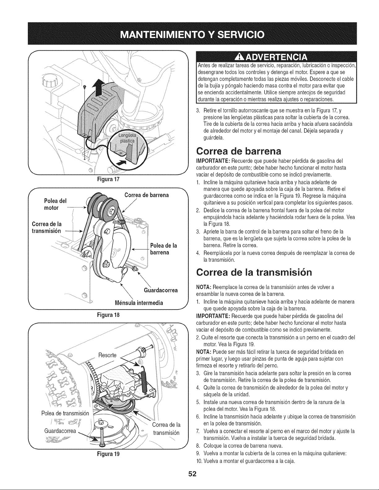
f
Figura 17
f
Correade barrena
Poleadel
motor
Correa de la
transmisi6n
t
Poleade la
t_barrena
f
_GuGuardacorrea
\
N_nsuia intermedia
Figura 18
Poleadetransmisi6n
Guardacorrea
Figura19
Antes de realizartareas de servicio, reparaci6n, iubricaci6n o inspecci6n,
desengrane todos los controles y detenga el motor. Espere a que se
detengan completamente todas ias piezas m6viles. Desconecte el cable
de la bujia y p6ngalo haciendo masa contra el motor para evitar que
se encienda accidentalmente. Utilice siempre anteojosde seguridad
_durante a operac 6n o m entras rea za a ustes o reparacones.
Retireel torniilo autorroscante que se muestra en ia Figura 17,y
presione las iengietas pla.sticasparasoltar ia cubierta de la correa.
Tire de ia cubierta de ia correa haciaarriba y hacia afuera saca.ndola
de alrededor del motor y el montaje del canal. Dejela separada y
gua.rdela.
Correa de barrena
IMPORTANTE: Recuerde que puede haber perdida de gasolina del
carburador en este punto; debe haber hecho funcionar el motor hasta
vaciar el dep6sito de combustible como se indic6 previamente.
1. Incline ia ma.quinaquitanieve hacia arriba y hacia adeiante de
maneraque quede apoyada sobre la caja de la barren& Retire el
guardacorrea como se indica en la Figura 19. Regrese ia ma.quina
quitanieve a su posici6n vertical para completar los siguientes pasos.
2. Deslice la correa de la barrena frontal fuera de la polea del motor
empuja.ndolahacia adelante y haciendola rodar fuera de la polea. Vea
la Figura 18.
3. Apriete la barra de control de ia barrena parasoltar el freno de la
barrena, que es la lengieta que sujeta la correa sobre la polea de la
barrena. Retire la correa.
4. Reempla.celapor la nueva correa despues de reemplazar la correa de
iatransmisi6n.
Correa de la transmisi6n
NOTA: Reemplacela correa de la transmisi6n antes de volver a
ensamblar la nueva correa de la barrena.
1. Incline ia m£quina quitanieve hacia arriba y hacia adelante de manera
que quede apoyada sobre la caja de la barren&
IMPORTANTE: Recuerde que puede haber perdida de gasolina del
carburador en este punto; debe haber hecho funcionar el motor hasta
vaciar ei dep6sito de combustible como se indic6 previamente.
2. Quite el resorte que conecta la transmisi6n a un perno en el cuadro del
motor.Vea ia Figura 19.
NOTA: Puedeset m£s fa.ciiretirar la tuerca de seguridad bridada en
primer iugar, y iuego usar pinzasde punta de aguja para sujetar con
firmeza el resorte y retirarlodel perno.
3. Gire ia transmisi6n hacia adelante para soltar ia presi6n en la correa
de transmisi6n. Retire ia correa de la polea de transmisi6n.
4. Quite ia correa de transmisi6n de alrededor de la polea del motor y
sa.quelade la unidad.
5. Instale una nueva correa de transmisi6n dentro de la ranura de la
polea del motor.Vea la Figura 18.
6. incline ia transmisi6n hacia adelante y ubique la correa de transmisi6n
en la polea de transmisi6n.
7. Vueiva a conectar el resorte al pemo en el marco del motor y ajuste la
transmisi6n. Vueiva a instaiar la tuerca de seguridad bridada.
8. Coloque la correa de barrena nueva.
9. Vuelva a montar la cubierta de la correa en la ma.quinaquitanieve:
10.Vuelva a montar el guardacorrea a la caja.
52
Ajuste del cable de la barrena
Es posible que se requieran ajustes peri6dicos del cable de controlde
la barrena debido ai estiramiento y al desgaste normal de la correa.
Se necesitara.najustes si las barrenas parecen temblar mientras giran
pero el motor mantiene su velocidad, o si sigue girando con ei control
de la barrena desengranado. Refierase a la secci6n de la Asamblea par
Ajuste del cable de la barrena
Siga el cronograma de mantenimiento que se presenta a continuaci6n. Algunos ajustes deben ser realizados peri6dicamente para
el mantenimiento adecuado de la unidad. Revise peri6dicamente todos los sujetadores y compruebe que esten bien ajustados.
Controle su calendario de mantenimiento completando el campo "Fechas de los servicios" que aparece a continuaci6n.
Antes de realizartareasde servicio,reparaci6n,iubricaci6no inspecci6n,desengranetodos los controlesy detenga el motor.Esperea que se detengan
completamentetodaslaspiezasm6viles.Desconecteel cablede labujiay p6ngalohaciendomasacontrael motorparaevitarqueseenciendaaccidentaimente.
Utilicesiempreanteojosde seguridaddurantelaoperaci6no mientrasrealizaajusteso reparaciones.
Antes de cada uso
Prograrna de rnantenirniento
Despu_sde cada uso
l ras5 horas 1.
Luegode 25 horas 1.
Antesde almacenar
Unavez por temporada
1. Revise el nivel de aceite del
motor.
1. Verifiqueelequipo.
2. Verifique el estado de las
zapatas.
1. Aceitedel motor
1. Compruebelascorreasen
V.
1. Sistema de combustible.
1. Puntosde pivote.
2. Sistema de transmisi6n yeje
de engranaje hexagonal.
3. Ejedelasruedas.
4. Bujfadeencendido.
1. Carguade aceitesi elnivelest,.
bajo
1. Limpieza
2. Limpieza
Cambio.
Ajusteo reparaci6nsegQnresulte
necesario.
1. Vaciado.
1. Lubricaci6n.
2. Lubricaci6n.
3. Engrasado.
4. Cambiodesernecesario.
53
Sinosevaa utilizael equipodurante30 dfasorn_.s,o sies el finaldelaternporadade nievey ya noexisteposibilidaddequenieve,es necesario
alrnacenarel equipode rnaneraadecuada.Sigalasinstruccionesdealrnacenarnientoquese indicanacontinuaci6nparagarantizarel rendirniento
rn_.xirnodelarn_.quinaquitanieveduranternuchosa_os.
PREPARACI6N DEL MOTOR
Losrnotoresquese alrnacenandurantern&sde30 dfas necesitan
serdrenadosdecombustibleparaevitarquese deterioreny se forrne
gornaenel sisternade combustibleo en las piezasprincipalesdel
carburador.Si lagasoNnade su motorse deterioraduranteel alrnace-
narniento,es posiblequedeba repararo reernplazarel carburadory
otroscornponentesdel sisternade combustible.
1. Elirninetodoel combustibledel tanquehaciendofuncionarel
motorhastaquese detenga.No intentede combustibleparael
motor.
2. Carnbieel aceitedel motor.
3. Extraigala bujfade encendidoy viertaen el cilindroaproxirna-
darnente1 onza(30 rnl)de aceitepara motorNrnpio.Tire varias
vecesdel arrancadorde retrocesoparadistribuirelaceitey
reinstalela bujfa.
4. Lirnpielos residuosde alrededordel motor,y debajo,alrededor,
y detr_.sdel silenciador.ApNqueunacapa delgadade aceiteen
todaslas _.reasque puedenNegara oxidarse.
• Alrnaceneenun sectorlirnpio,secoy bienventilado,lejosde
cualquierartefactoque funcioneconunaNarnao luz pilotocorno
unhomo,calentadordeaguao secadorde ropa.Evitecualquier
sectorcon un motorel_ctricoqueproduzcachispaso dondese
utilicenherrarnientasel_ctricas.
Nuncaalrnacenelarn_.quinaquitanieveconcombustibleen el
tanqueen un espaciocerradooen _.reascon pocaventilaci6n,
dondelosgases del combustiblepuedanalcanzarel fuego,chispas
o unaluz pilotocornola que tienenalgunoshornos,calentadoresde
agua,secadoresde ropao algQnotto dispositivoagas.
PREPARACION DE LA iVlAQUINA QUITANIEVE
1. Cuandoalrnacenela rn&quinaquitanieveen ungalp6nde
dep6sitornet_.licoo con pocaventilaci6n,tengaespecialcuidado
de realizarleuntratarnientoanti- oxidanteal equipo.Useaceite
ligeroo silic6npararecubrirel equipo,especialrnentelas
cadenas,los resortes,loscojinetesy loscables.
2. Elirninetodo el polvodel exteriordel motory del equipo.
3. Sigalas recornendacionesde lubricaci6nen la secci6nde
mantenirnientodeestemanual.
4. Alrnaceneel equipoen un_.readespejaday seca.
• Si es posible,evite sectoresdealrnacenarnientocon rnucha
hurnedad.
• Mantengael motorniveladoen el alrnac_n.Lainclinaci6ndel
motorpuedecausarperdidasde combustibleo aceite.
54
Antesde realizarcuaiquiertipo de mantenimientoo servicio,desenganche
todos loscontrolesy detengael motor.Esperea que se detengancomple-
tamentetodas laspiezas m6viles.Desconecteel cablede la bujh y p6ngalo
haciendomasacontraei motorparaevitarquese enciendaaccidentalmente.
Utilicesiempreanteojosde seguridaddurantela operaci6no mientrasrealiza
ajusteso reparaciones.
Esta secci6nanaliza problemasmenores de servicio.Paraubicar el Centrode Servicio Sears m_s cercanoo paraprogramarun servi-
eio, simplemente eomuniquese con Sears al tel_fono 1-800-4-MY-HOME®.
Elmotor no arranca 1. El control del cebador no estfi en la posicidn ON (encendido).
2. Se ha desconectado el cable de la bujia.
3. La bujia nofuncionacorrectamente.
4. El depdsitode combustibleestfi vacio o el combustiblese
ha echadoa perder.
El motorno est_cebado.
Motoren marcha
errAtica/RPM
incompatibles(o
aumentode la caza)
5,
6.
1.
2.
3.
1. Pongael control del cebadoren laposici6nON (encendido).
2. Conecteel cable a la bujia.
3. Limpiela,ajustela distanciadisruptivao cambiela.
4. Lleneeltanque con gasolinalimpia y fresca.
La Ilavede seguridadno se ha insertado.
El motorest_ funcionandoen la posici6n"choke"(c.
La lineadel combustibleest_tapadao el combustiblees
viejo.
Hayagua o suciedaden elsistemade combustible.
Es necesarioregularel carburador.
MAsgobernadosmotor
El carburadorno est_ bienregulado.
Haypiezas queest_nflojas o la barrenaest_da_ada.
El cablede la bujia est_flojo.
El orificiode ventilaci6ndel tap6n de combustibleest_
obstruido.
El cablede la transmisi6nnecesitaun ajuste.
La correa de transmisi6nest_floja o da_ada.
El conjuntodel canal est_tapado.
5. Cebe el motortal comose explic6en la secci6n
Funcionamiento.
6. Insertela llavetotalmentedentrodel interruptor.
1,
2.
Muevala palancadel cebador a la posici6nRUN.
Limpiela linea del combustibley Ileneel dep6sitocon
gasolinalimpiay nueva.
Poneren marchael motorhastaque se detengaparavaciar
eldep6sitode combustible.Vuelvaa Ilenarel dep6sitocon
combustiblenuevo.
Comuniquesecon un centrode servicioSears.
Comuniquesecon un centrode servicioSears.
4, 4,
5. 5.
Elmotorrecalienta 1. 1. Contactecon su centrode partesy reparacionesSears.
Vibraci6nexcesiva 1. 1. Detengael motorde inmediatoydesconecteel cablede la
bujia.Ajustetodoslos pernosy lastuercas.Si lavibraci6n
continQa,Ileve la unidada reparara un centrode partesy
reparaci6nSears.
Perdidade potencia 1. 1. Conectey ajusteel cablede la bujia.
2. 2. Retireel hieloy la nieve del tap6n de combustible.
Compruebequeel orificiode ventilaci6nno este obstruido.
La unidad no se 1. 1. Ajuste elcable del control de transmisi6n.Consultela
autoimpulsa secci6nde Servicioy Mantenimiento.
2. 2. Reemplacela correadetransmisi6n. Consultelasecci6n de
Servicioy Mant.
La unidad no 1. 1.
descarga la nieve
2. Hayun objeto extra6oen labarrena.
3. El cablede la barrenanecesitaun ajuste.
4. La correa de la barrenaest_floja o da6ada.
5. El o los pasadoresde cuchillaest,(n) quebrado(s).
Detengael motorde inmediatoy desconecteel cablede la
bujia.Limpieel montajedel canal y el interiorde la cajade
la barrenacon la herramientade limpiezao unavarilla.
2. Detengael motorde inmediatoy desconecteel cable de la
bujia.Retireel objetode la barrenacon laherramientade
limpiezao unavarilla.
3. Ajusteelcabledel control de la barrena.Consultela secci6n
Montaje.
4. Reemplacela correade la barrena.Consultela secci6nde
Servicioy Mantenimiento.
5. Reemplacecon nuevo(s) pasador(es)de cuchilla.
55
MTD CONSUMER GROUP, iNC. (MTD), el Bordo de Recursos de Aire de California (CARB)
y la Agencia de Protecci6n Medioambiental de Estados Unidos (U. S. EPA)
Declaraci6n de Garantia del Sistema de Control de Emisiones
(Derechos y obligaciones del propietario seg_n la garantia contra defectos)
LACOBERTURADESISTEMADECONTROLDEEMISIONES APLICABLEA MOTORESCERTIFICADOSCOMPRADOSENCALIFORNIA
EN2005 Y A PARTIRDE ENTONCES,QUESON USADOSEN CALIFORNIA,Y HASTAANO2005DE MODELOCERTIFICADOY MOTORES
POSTERIORESQUESON COMPRADOSY USADOSENOTRAPARTEEN LOSESTADOSUNIDOS.
Californiayen otra parteen la Coberturade Garantiade DefectosdeControlde Emisi6nde los EstadosUnidos
El Bordode Recursosde Airede California(CARB),la U.S. EPAy MTDsecomplacenenexplicarla garantiadel sistemade controlde emisiones
de su motorparaequipotodo terreno,modelo,aSo2005y versionesposteriores.EnCalifornia,los nuevosmotorespequeSospara equipotodo
terrenose debendise5ar,fabricary equiparparacumplirconest_.ndaresde antinieblat6xicade estados.Enotraparteen los EstadosUnidos,
el nuevonocamino,motoresdeignici6ndechispacertificadospara el modelo2005y m_.starde,debe encontrareljuegode est_.ndaressimilar
adelantepor los EstadosUnidos.EPA.MTDdebe garantizarel sistemade controlde emisionesde su motorpor el periodode tiempoindicadom&s
abajo,siemprey cuandono hayaexistidousoincorrecto,negligencianimantenimientoinadecuadode su motorpequeBoparaequipotodoterreno.
El sistemade controlde emisionespuedeincluirpiezascomo,por ejemplo,el carburador,sistemadeinyecci6nde combustible,el sistemade
encendido,el catalizador,losdep6sitosdecombustible,abastecedecombustiblelineas,gorrasde combustible,v&lvulas,latas,filtros,mangueras
devapor,abrazaderas,conectoresy otroscomponentesrelacionadoscon lasemisiones.
Dondeexistaunacondici6ncubiertaporla garantia,MTDreparar&su motor pequeBopara equipotodoterrenosincostoalgunoincluyendoel
diagn6stico,laspiezasy la manode obra.
COBERTURA DE LA GARANTJA DEL FABRICANTE:
Estesistemade controlde emisionesse garantizaporel t@rminodedos a5os.Si algunapiezade su motorrelacionadacon lasemisioneses
defectuosa,MTD reparar&o sustituir&dichapieza.
RESPONSABJLIDADES DEL PROPIETARIO SEGUN LA GARANTJA:
Comopropietariode un motorpequeSode equipotodoterreno,ustedes responsablede realizarel mantenimientonecesarioquefigura enel
manualdel propietario.MTDle recomiendaque conservetodoslos recibosquecubrenlos serviciosdemantenimientodel motorpeque5opara
equipotodoterreno,noobstanteIo cual MTDnopodr&denegarel cumplimientode la garantiaQnicamenteporlafaltade reciboso porsu imposi-
bilidaddeasegurarque se realizar_.ntodos los serviciosde mantenimientoprogramado.
Comopropietariodel motorpeque5oparaequipotodo terreno,sinembargo,ustedtambi@ndebesaberque MTDpuede denegarla coberturadela
garantiasi su motorpeque5opara equipotodoterrenoo unapiezadel mismofallandebidoa usoincorrecto,negligencia,mantenimientoindebido
o a modificacionesnoaprobadas.
Ustedes responsablede presentarlacortadoradecespedal centrode distribuci6no de mantenimientode MTDCONSUMERGROUP,INC.tan
prontocomo aparecierael problem& Lasreparacionescubiertaspor lagarantiasedebenIlevaracabo en un lapsorazonableque noexcedade
30dias.Si desearealizaralgunaconsultacon respectoa la coberturade lagarantia,debeponerseen contactocon su distribuidorlocalde MTD.
Paracomunicarseconla LineadeAsistenciaal Clientede Distribuidoresde MTD,Ilameal nQmero(877)282-8684.
REQUERJMJENTOS DE GARANTJA SOBRE DEFECTOS PARA MOTORES PEQUENOS DE EQUJPO TODO TERRENO
DE 1995YVERSJONES POSTERJORES:
Estasecci6nse aplicaa motorespeque5osde equipotodo terrenode 1995y versionesposteriores.El periodode garantiacomienzaa partirde la
fechaen queel motoro el equipo seentreganal compradorfinal.
(a) Coberturade la garantiacontraemisionesgenerales
MTDgarantizaal compradorfinaly a cada compradorsubsiguientequeel motor:
(1)hasido diseSado,construidoy equipadode maneraque cumplacontodaslas regulacionesvigentesadoptadaspor el Departamentodelos
Recursosde Aire en virtud a suautoridadconferidaen los capitulos1y 2, Parte5, Divisi6n26 del C6digode Saludy Seguridad;y
(2)est,. librede defectosen los materialesyen la manode obraquecausenlafalla de una piezabajogarantiaque seaid@nticaentodoslos
aspectosmaterialesa la piezacomo aparecedescriptaen la aplicaci6ndelfabricantedel motorpara certificaci6npor un periodode dos a5os.
_arantia sobre piezasrelacJonadasconemisJonesse interpretar_,de la sJguientemanera:
(1)Cualquierpiezacubiertaporgarantiaque no est@programadaparasu reemplazosegQnel mantenimientorequeridoen las instrucciones
escritasdela Subsecci6n(c) debe estar garantizadapor unperiodode garantiadefinidoen la Subsecci6n(a)(2). Sila piezafalladurante
el periododecoberturadela garantia,la mismaser_.reparadao reemplazadaporMTD de acuerdocon la Subsecci6n(4) a continuaci6n.
Cualquierpiezareparadao reemplazadasegQnla garantiasegarantizarB,porel resto del periodode garantia.
(2) Cualquierpiezacubiertapor garantiaqueest@programadasolopara inspecci6nregularen las instruccionesescritasde la Subsecci6n
(c) debe estargarantizadaporun periododegarantiadefinidoenla Subsecci6n(a) (2). Unadeclaraci6nen dichasinstruccionesporescrito
alefectode "reparaci6no reemplazosegQnseanecesario"no reducir_,el periodode coberturade la garantia.Cualquierpiezareparadao
reernplazadasegQnlagarantiasegarantizar_,porelrestodelperiododegarantia.
(3) Cualquierpiezagarantizadaqueest_prograrnadaparareernplazosegQnelrnantenirnientorequeridodeconforrnidadconlasinstruc-
clonesescritasdelaSubsecci6n(c)segarantizaporelperiododetiernpoanterioralaprirnerafechadereernplazoprograrnadaparaesa
pieza.Silapiezafallaantesdelprimerreernplazoprogramatic,larnisrnaser_.reparadaoreernplazadaporMTDdeacuerdoconlaSubsecci6n
(4)acontinuaci6n.Cualquierpiezareparadaoreernplazadabajogaranfiasegarantizar_,porelrestodelperiodoanterioralprimerreernplazo
programaticpuntualparaesapieza.
(4)Lareparaci6noelreernplazodecualquierpiezagarantizadadeconforrnidadconlasdisposicionesdelagaranfiaqueaquiseestipulase
deberealizarenuncentrodegaranfiasincostoalgunoparaelpropietario.
(5)SinperjuiciodelasdisposicionesdelaSubsecci6n(4)anterior,losserviciosoreparacionescubiertosporlagaranfiadebensersurnin-
istradosportodosloscentrosdedistribuci6ndeMTDquetenganlafranquiciapararealizarreparacionesyrnantenirnientoalosrnotoresen
cuesti6n.
(6)ElpropietarionodebeafrontarningQncargoparatrabajosdediagn6sticoqueIlevenalaconclusi6ndequeunapiezabajogaranfiapresenta
efectivarnentedefectos,siernpreycuandodichodiagn6sticoseaIlevadoacaboenuncentrocubiertoporlagarantia.
(7)Elfabricantedelmotoresresponsableporda_oscausadosaotroscornponentesdernotoresderivadosdelafallabajogaranfiadecualquier
piezagarantizada.
(8)DurantetodoelperiododegaranfiadelmotordefinidoenlaSubsecci6n(a)(2),MTDrnantendr_,unsurninistrodepiezascubiertaspor
garantiasuficienteparasatisfacerladernandaesperadaparatalespiezas.
(9)Cualquierpiezadereernplazosepodr_,usarparaelcurnplirnientodelrnantenirnientooreparacionesbajogaranfia,ysesurninistrar_,sin
cargoalpropietario.Dichousonoreducir_,lasobligacionesdegarantiadeMTD.
(10)Nosepodr_.nusarpiezasadicionalesnirnodificadasquenoest_nexentasdeacuerdoconelDepartarnentodelosRecursosdelAire(Air
ResourcesBoard).Elusodepiezasadicionalesornodificadasnoexentasser_.causasuficienteparaanularunreclarnobajogaranfiarealizado
deacuerdoconestearticulo.Elfabricantedelmotornotendr_,responsabilidad,enconforrnidadconestearticulo,degarantizarfallasdepiezas
garantizadasquefuerencausadasporelusodeunapiezanoexentaadicionalornodificada.
.(c)MTDincluir_,una copiade la siguientelistade piezasbajo garantiacontraernisionescon cadanuevomotor,utilizandolas partesde la lista
a_plicablesal motor.
(1)Sisternade rnedici6ndecombustible
• Sisternade rnejoraparainicioenfrio (cebadosuave)
• Carburadory cornponentesinternos
• Bornbade combustible
• Dep6sitode combustible
(2) Sisternade inducci6nde aire
• Filtrode aire
• Colectorde entrada
(3) Sisternade encendido
• Bujia(s)
• Sisternadeencendidopor magneto
(4)Sisternade escape
• Catalizador
• SAI (v_Jvulade Ca_a)
(5) Cornponentesvariosutilizadosen el sisternaanterior
• V_Jvulase interruptoresde vado, ternperatura,posici6nsensiblesal tiernpo
• Conectoresy rnontajes
(6)Controlde Evaporative
• Manguerade CombustiblecertificadaparaARB evaporativeernisi6nde 2006.
• Abrazaderasde Manguerade Combustible
• Gorrade combustibleatada
• Latade carb6n
• Lineasdevapor
GD0C-100174Rev.B
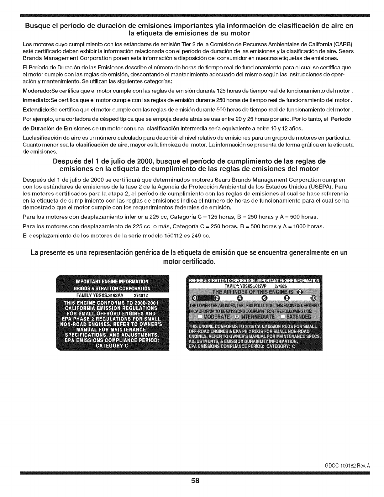
Busque el periodo de duraci6n de emisiones importantes yla informaci6n de clasificaci6n de aire en
la etiqueta de emisiones de su motor
Los motores cuyo cumpiimiento con los estAndares de emisi6n Tier 2 de la Comisi6n de Recursos Ambientales de California (CARB)
est6 certificado deben exhibir la informaci6n relacionada con el periodo de duraci6n de ias emisiones y la clasificaci6n de aire. Sears
Brands Management Corporation ponen esta informaci6n a disposici6n del consumidor en nuestras etiquetas de emisiones.
Ei Periodo de Duraci6n de las Emisiones describe el nQmero de horas de tiempo real de funcionamiento para el cuai se certifica que
el motor cumpie con ias reglas de emisi6n, descontando el mantenimiento adecuado del mismo segQn las instrucciones de oper-
aci6n y mantenimiento. Se utilizan las siguientes categonas:
Moderado:Se certifica que el motor cumpie con las reglas de emisi6n durante 125 horas de tiempo real de funcionamiento del motor.
Inmediato:Se certifica que el motor cumpie con las reglas de emisi6n durante 250 horas de tiempo real de funcionamiento del motor.
Extendido:Se certifica que el motor cumpie con las reglas de emisi6n durante 500 horas de tiempo real de funcionamiento del motor.
Por ejemplo, una cortadora de c6sped tJpica que se empuja desde arras se usa entre 20 y 25 horas por aSo. Por Io tanto, el Periodo
de Duraci6n de Emisiones de un motor con una clasificaci6n intermedia sena equivaiente a entre 10 y 12 aSos.
Laciasificaci6n de aire es un nQmero calculado para describir el nivel relativo de emisiones para un grupo de motores en particular.
Cuanto menor sea la clasificaci6n de aire, mayor es la limpieza del motor. La informaci6n se presenta de forma grAfica en la etiqueta
de emisiones.
Despu_s del 1 de julio de 2000, busque el periodo de cumplimiento de las reglas de
emisiones en la etiqueta de cumplimiento de las reglas de emisiones del motor
Despu6s del 1 de julio de 2000 se certificarA que determinados motores Sears Brands Management Corporation cumplen
con los estAndares de emisiones de la fase 2 de la Agencia de Protecci6n Ambientai de los Estados Unidos (USEPA). Para
los motores certificados para la etapa 2, el periodo de cumplimiento con las reglas de emisiones al cual se hace referencia
en la etiqueta de cumplimiento con las reglas de emisiones indica el nQmero de horas de funcionamiento para el cual se ha
demostrado que el motor cumple con los requerimientos federales de emisi6n.
Para los motores con desplazamiento inferior a 225 cc, Categoria C = 125 horas, B = 250 horas y A = 500 horas.
Para los motores con desplazamiento de 225 cc o mAs, Categoria C = 250 horas, B = 500 horas y A = 1000 horas.
El desplazamiento de los motores de la serie modelo 150112 es 249 cc.
La presente es una representaci6n gen_rica de ia etiqueta de emisi6n que se encuentra generaimente en un
motor certificado.
FAMILYYBSXS.3192VA 274812
GDOC-100182Rev.A
58
Felicitacionespor haberrealizadounaadquisici6ninteligente.El
productoCraftsman@que ha adquiridoest_dise_adoy fabricado
parabrindarrnuchosa_osde funcionarnientoconfiable.Perocorno
todoslos productosa vecespuederequerirde reparaciones.Esen
esernornentocuandoel disponerde unAcuerdode protecci6npara
reparacionesle puedeahorrardineroy problernas.
A continuaci6nsedetallanlos puntosincluidosenel Acuerdo:
• Servicio experto prestadopornuestros10,000especialistasen
reparacionesprofesionales
• Servicio ilirnitadosincargoparalaspiezasy la rnanode obra en
todaslas reparacionescubiertas
• Reernplazodel productohasta1500d61aressi no es posible
repararel productocubierto
• Descuentode 10%del precionormaldel servicioy de las piezas
relacionadascon el rnisrnoque no est_ncubiertasporel acuerdo;
adern&s,10%del precionormalde la verificaci6nde rnantenirniento
preventivo
• Ayudar_pidapottel_fono- IoIlarnarnosResoluci6nR_pida- el
apoyotelef6nicode unCharnuscaal representante.Pienseen
nosotroscornoel manual"de un due_ohablador."
Unavezadquiridoel Acuerdo,puedeprograrnarel serviciocon
tan s61orealizarunaIlarnadatelef6nica.PuedeIlarnarencualquier
mornentodeldia o de la nocheo prograrnarun servicioen linea.
ElAcuerdode Protecci6nde Reparaci6nes una cornprasin riesgo.
Siustedanulaporalgunaraz6nduranteel periodode garantiade
producto,proporcionarernosun reernbolsoIleno.O,un reernbolso
prorrateadoencualquiermornentodespu_sdel periodode garantia
de productoexpira, iAdquieraboysu acuerdode protecci6npara
reparaciones!
Seaplican deterrninadaslirnitaciones y exclusiones.Paraobtener
inforrnaci6nadicional y preciosen los Estados UnidosIlarne al
1-800-827-6655.
El*Coverage en Canad_variaen algunosarticulos. Paradetalles
Ilenosla IlarnadaCharnuscaCanad_en 1-800-361-6665.
Servicio de instalaci6nde Sears
Sideseasolicitarla instalaci6nprofesionalde Searsde aparatos
dorn_sticos,dispositivosparaabrirportones,calentadoresde agua
y otrosarficulosdorn_sticosirnportantes,en los EstadosUnidoso
Canad_Ilarneal 1-800-4-MY-HOME®.
59

Your Home
For troubleshooting, product manuals and expert advice:
managernylife
www.managemylife.com
For repair - in your home - of all major brand appliances,
lawn and garden equipment, or heating and cooling systems,
no matter who made it, no matter who sold it!
For the replacement parts, accessories and
owner's manuals that you need to do-it-yourself.
For Sears professional installation of home appliances
and items like garage door openers and water heaters.
1-800-4-MY-HOME ® (1-800-469-4663)
Call anytime, day or night (U.S.A. and Canada)
www.sears.com www.sears.ca
Our Home
For repair of carry-in items like vacuums, lawn equipment,
and electronics, call anytime for the location of your nearest
Sears Parts & Repair Service Center
1-800-488-1222 (U.S.A.) 1-800-469-4663 (Canada)
www.sears.com www.sears.ca
To purchase a protection agreement on a product serviced by Sears:
1-800-827-6655 (U.S.A.) 1-800-361-6665 (Canada)
Para pedir servicio de reparaci6n
a domicilio, y para ordenar piezas:
1-888-SU-HOGAR ®
(1-888-784-6427)
www.sears.com
Au Canada pour service en frangais:
1-800-LE-FOYER Mc
(1-800-533-6937)
www.sears.ca
® Registered Trademark / TMTrademark of KCD IP, LLC in the United States, or Sears Brands, LLC in other countries
® Marca Registrada ! TMMarca de Fabrica de KCD IP, LLC en Estados Unidos, o Sears Brands, LLC in otros paises
MCMarque de commerce ! MDMarque deposee de Sears Brands, LLC