ICRIIFT$1VIRN°I
Operator's Manual
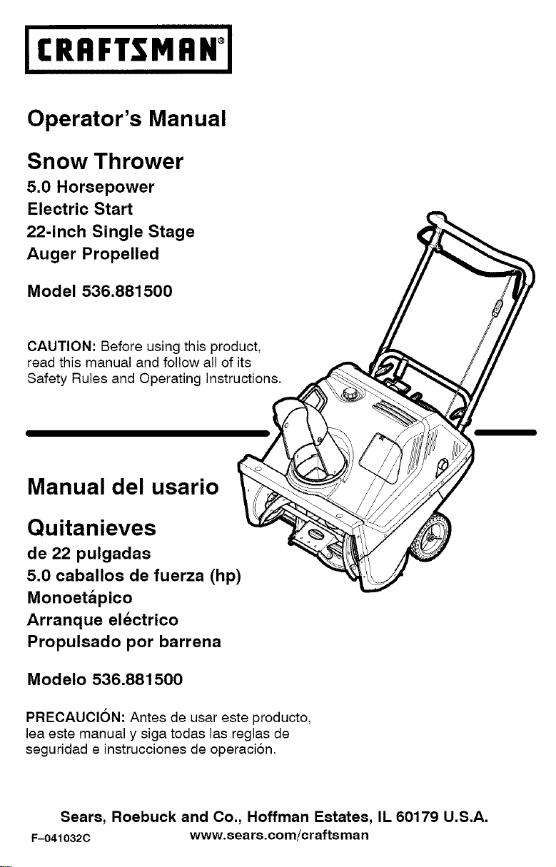
Snow Thrower
5.0 Horsepower
Electric Start
22-inch Single Stage
Auger Propelled
Model 536.881500
CAUTION: Before using this product,
read this manual and follow all of its
Safety Rules and Operating Instructions.
Manual del usario
Quitanieves
de 22 pulgadas
5.0 caballos de fuerza (hp)
Monoetapico
Arranque electrico
Propulsado por barrena
Modelo 536.881500
PRECAUCION: Antes de usar este producto,
lea este manual y siga todas las reglas de
seguridad e instrucciones de operaci6n,
Sears, Roebuck and Co., Hoffman Estates, IL 60179 U.S.A.
F-041032C www.sears.com/craftsman
WARRANTY STATEMENT ...... 2
SAFETY RULES ............... 2
INTERNATIONAL SYMBOLS .... 4
ASSEMBLY ................... 6
OPERATION .................. 8
MAINTENANCE ............... 15
SERVICE AND ADJUSTMENT... 19
STORAGE .................... 22
TROUBLE SHOOTING CHART .. 23
REPAIR PARTS ................ 28
ENGINE REPAIR PARTS ........ 42
SPANISH (ESPAI_IOL) .......... 50
PARTS ORDERING/SERVICE ,., 76
|f;l'_1-'l-'r'_1_| h'd_._
LIMITED TWO-YEAR WARRANTY ON CRAFTSMAN SNOW THROWER
For two years from the date of purchase, when this Craftsman Snow thrower is maintained,
lubricated, and tuned up according to the operating and maintenance instructions in the
owner's manual, Sears will repair, free of charge, any defect in material or workmanship.
If this Craftsman Snow thrower is used for commercial or rental purposes, this warranty ap-
plies for only 90 days from the date of purchase.
This warranty does not cover the following:
• Items which become worn during normal use, such as spark plugs, drive belts and shear
pins.
• Repair necessary because of operator abuse or negligence, including bent crankshafts
and the failure to maintain the equipment according to the instructions contained in the
owner's manual.
WARRANTY SERVICE IS AVAILABLE BY RETURNING THE CRAFTSMAN SNOW
THROWERTO THE NEAREST SEARS SERVICE CENTER IN THE UNITED STATES.
THIS WARRANTY APPLIES ONLY WHILE THIS PRODUCT IS IN USE IN THE UNITED
STATES.
This warranty gives you specific legal rights, and you may also have other rights which may
vary from state to state.
Sears, Roebuck and Co., D817WA, Hoftman Estates. IL 60179
LOOK FOR THIS SYMBOL TO POINT OUT IMPORTANT SAFETY PRECAUTIONS.
IT MEANS--ATTENTION!!! BECOME ALERT!t! YOUR SAFETY IS INVOLVED.
_ WARNING: Always discon-
nect the spark plug wire
and place it where it cannot
make contact with spark plug to
prevent accidental starting during:
Preparation, Maintenance, or Stor-
age of your snow thrower.
Engine Exhaust, some of its constituents, and
certain vehicle components contain or emit
chemicals known to the State of California to
cause cancer and birth defects or other repro-
ductive harm.
Battery posts, terminals and related accessories
contain lead and lead compounds, chemicals
known to the State of California to cause cancer
and birth defects or other reproductive harm.
WASH HANDS AFTER HANDLING.
IMPORTANT: Safety standards re-
quire operator presence controls to
minimize the risk of injury. Your snow
thrower is equipped with such controls.
Do not attempt to defeat the function of
the operator presence control under any
circumstances.
F 0410320 2
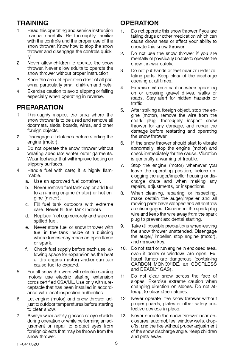
TRAINING
1. Read this operating and service instruction
manual carefully. Be thoroughly familiar
with the controls and the proper use of the
snow thrower. Know how to stop the snow
thrower and disengage the controls quick-
ly.
2. Never allow children to operate the snow
thrower. Never allow adults to operate the
snow thrower without proper instruction.
3. Keep the area of operation clear of all per-
sons, particularly small children and pets.
4. Exercise caution to avoid slipping or falling
especially when operating in reverse.
PREPARATION
1. Thoroughly inspect the area where the
snow thrower is to be used and remove all
doormats, sleds, boards, wires, and other
foreign objects.
2. Disengage all clutches before starting the
engine (motor).
3. Do not operate the snow thrower without
wearing adequate winter outer garments.
Wear footwear that will improve footing on
slippery surfaces.
4. Handle fuel with care; it is highly flam-
mable.
a. Use an approved fuel container.
b. Never remove fuel tank cap or add fuel
to a running engine (motor) or hot en-
gine (motor).
c. Fill fuel tank outdoors with extreme
care. Never fill fuel tank indoors.
d. Replace fuel cap securely and wipe up
spilled fuel.
e. Never store fuel or snow thrower with
fuel in the tank inside of a building
where fumes may reach an open flame
or spark.
f. Check fuel supply before each use, al-
lowing space for expansion as the heat
of the engine (motor) and/or sun can
cause fuel to expand.
5. For all snow throwers with electric starting
motors use electric starting extension
cords certified CSA/UL. Use only with a re-
ceptacle that has been installed in accord-
ance with local inspection authorities.
6. Let engine (motor) and snow thrower ad-
just to outdoor temperatures before starting
to clear snow.
7. Always wear safety glasses or eye shields
during operation or while performing an ad-
justment or repair to protect eyes from
foreign objects that may bethrown from the
snow thrower.
F 0410320
OPERATION
1. Do not operate this snow thrower ifyou are
taking drugs or other medication which can
cause drowsiness or affect your ability to
operate this snow thrower.
2. Do not use the snow thrower if you are
mentally or physically unable to operate the
snow thrower safely.
3. Do not put hands or feet near or under ro-
tating parts. Keep clear of the discharge
opening at all times.
4. Exercise extreme caution when operating
on or crossing gravel drives, walks or
roads. Stay alert for hidden hazards or
traffic.
5. After striking a foreign object, stop the en-
gine (motor), remove the wire from the
spark plug, thoroughly inspect snow
thrower for any damage, and repair the
damage before restarting and operating
the snow thrower.
6. If the snow thrower should start to vibrate
abnormally, stop the engine (motor) and
check immediately for the cause. Vibration
is generally a warning of trouble.
7. Stop the engine (motor) whenever you
leave the operating position, before un-
clogging the auger/impeller housing or dis-
charge chute and when making any
repairs, adjustments, or inspections.
8. When cleaning, repairing, or inspecting,
make certain the auger/impeller and all
moving parts have stopped and all controls
are disengaged. Disconnect the spark plug
wire and keep the wire away from the spark
plug to prevent accidental starting.
9. Take all possible precautions when leaving
the snow thrower unattended. Disengage
the auger/ impeller, stop engine (motor),
and remove key.
10. Do not start or run engine in enclosed area,
even if doors or windows are open. Ex-
haust fumes are dangerous (containing
CARBON MONOXIDE, an ODORLESS
and DEADLY GAS).
11. Do not clear snow across the face of
slopes. Exercise extreme caution when
changing direction on slopes. Do not at-
tempt to clear steep slopes.
12. Never operate the snow thrower without
proper guards, plates or other safety pro-
tective devices in place.
13. Never operate the snow thrower near en-
closures, automobiles, window wells, drop-
offs, and the like without proper adjustment
of the snow discharge angle. Keep children
and pets away.
14.Donotoverloadthesnowthrowercapacity
byattemptingtoclearsnowattoofasta
rate.
15.Neveroperatethesnowthrowerathigh
transportspeedsonslipperysurfaces.
Lookbehindandusecarewhenbacking
up.
16.Neverdirectdischargeatbystandersor
allowanyoneinfrontofthesnowthrower.
17.Disengagepowertothecollector/impeller
whensnowthroweristransportedornotin
use.
18.Useonlyattachmentsandaccessoriesap-
provedbythemanufacturerofthesnow
thrower(suchastirechains,electricstart
kits,ect.).
19.Neveroperatethesnowthrowerwithout
goodvisibilityorlight.Alwaysbesureof
yourfootingandkeepafirmholdonthe
handles.Walk;neverrun.
20.Donotover-reach.Keepproperfooting
andbalanceatalltimes.
21.Donotattempttousesnowthrowerona
roof.
MAINTENANCE AND STORAGE
1. Check shear bolts and other bolts at fre-
quent intervals for proper tightness to be
sure the snow thrower is in safe working
condition.
2. Store the snowthrower away from ignition
sources or appliances that have a pilot
light, such as hot water and space heaters,
clothes dryers, etc.... Allow the engine
(motor) to cool before storing in any enclos-
ure.
3. Always refer to operator's guide instruc-
tions for important details if the snow
thrower is to be stored for an extended
period.
4. Maintain or replace safety and instruction
labels, as necessary.
5. Run the snow thrower a few minutes after
throwing snow to prevent freeze-up of the
auger/impeller.
,_ WARNING: This snow thrower isfor use on sidewalks, driveways
and other ground level surfaces.
Caution should be exercised while using on
steep sloping surfaces. DO NOT USE
SNOW THROWER ON SURFACES ABOVE
GROUND LEVEL such as roofs of resi-
dences, garages, porches or other such
structures or buildings.
_"_"_'_o_l_..-_
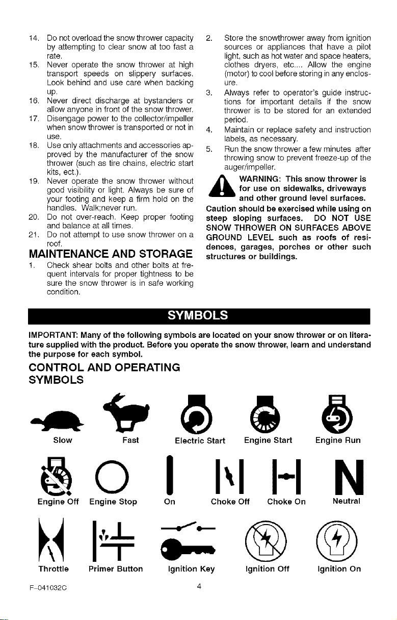
IMPORTANT: Many of the following symbols are located on your snow thrower or on litera-
ture supplied with the product. Before you operate the snow thrower, learn and understand
the purpose for each symbol.
CONTROL AND OPERATING
SYMBOLS
Slow Fast Electric Start Engine Start Engine Run
I H N
Engine Off Engine Stop On Choke Off Choke On Neutral
Throttle Primer Button Ignition Key
®@
Ignition Off Ignition On
F 0410320 4
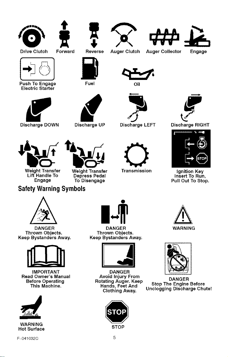
Drive Clutch Forward Reverse Auger Clutch
Push To Engage Fuel Oil
Electric Starter
Discharge UP Discharge LEFT
Engage
Discharge DOWN
MVV
Auger Collector
Discharge RIGHT
Weight Transfer Weight Transfer Transmission Ignition Key
Lift Handle To Depress Pedal Insert To Run,
Engage To Disengage Pull Out To Stop.
DANGER WARNING
Thrown Objects.
Keep Bystanders Away.
DANGER
Stop The Engine Before
Unclogging Discharge Chutet
Safety Warning Symbols
DANGER
Thrown Objects.
Keep Bystanders Away.
IMPORTANT
Read Owner's Manual
Before Operating
This Machine.
DANGER
Avoid Injury From
Rotating Auger. Keep
Hands, Feet And
Clothing Away.
WARNING
Hot Surface
STOP
F 0410320 5
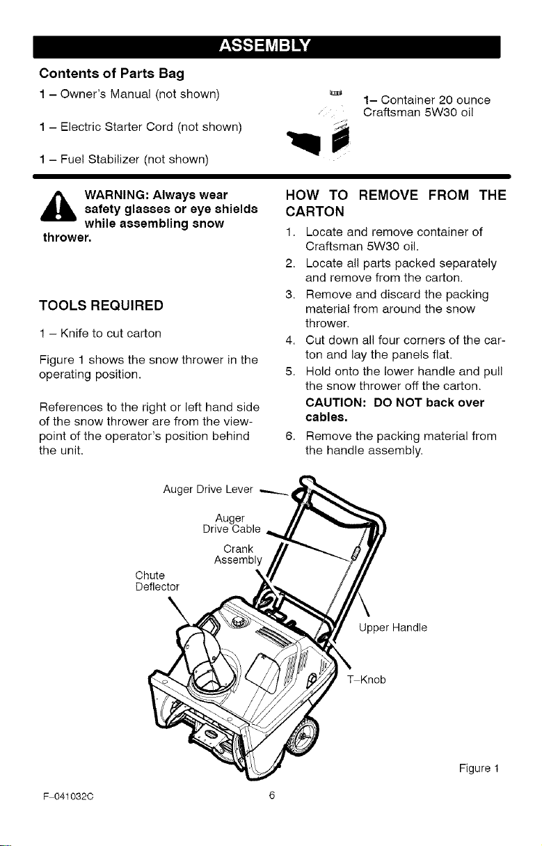
Contents of Parts Bag
1 - Owner's Manual (not shown)
1 - Electric Starter Cord (not shown)
1 - Fue! Stabilizer (not shown)
1- Container 20 ounce
, Craftsman 5W30 oi!
_hb ARNING: Always wearsafety glasses or eye shields
while assembling snow
thrower.
TOOLS REQUIRED
1 - Knife to cut carton
4.
Figure 1 shows the snow thrower in the
operating position. 5.
References to the right or left hand side
of the snow thrower are from the view-
point of the operator's position behind
the unit.
HOW TO
CARTON
1.
2.
3.
REMOVE FROM THE
Locate and remove container of
Craftsman 5W30 oil.
Locate all parts packed separately
and remove from the carton.
Remove and discard the packing
material from around the snow
thrower.
Cut down all four corners of the car-
ton and lay the panels flat.
Hold onto the lower handle and pull
the snow thrower oft the carton.
CAUTION: DO NOT back over
cables.
Remove the packing material from
the handle assembly.
Auger Drive Lever
Auger
Drive Cable
Crank
Assembly
Chute
Deflector
Upper Handle
_Knob
Figure 1
F 041032C 6
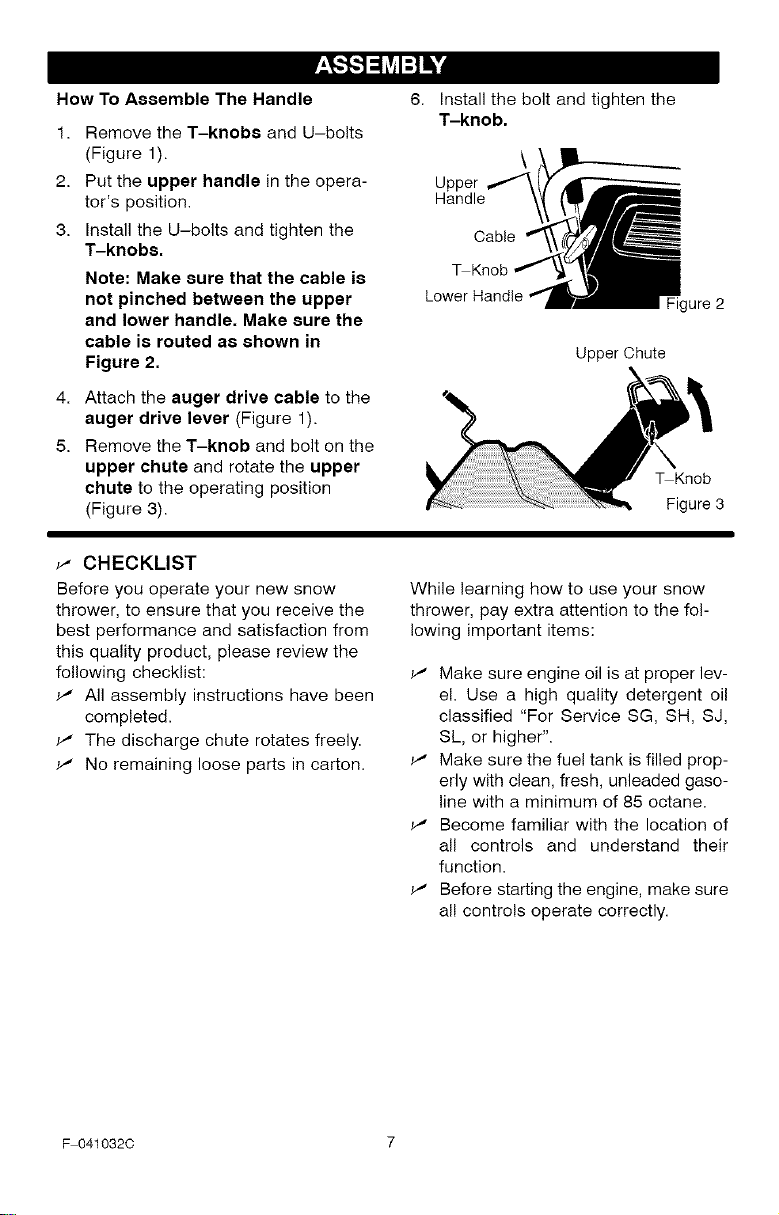
How To Assemble The Handle
1.
2.
3.
Remove the T-knobs and U-bolts
(Figure 1).
Put the upper handle in the opera-
tor's position.
Install the U-bolts and tighten the
T-knobs.
Note: Make sure that the cable is
not pinched between the upper
and lower handle. Make sure the
cable is routed as shown in
Figure 2.
4.
5.
Attach the auger drive cable to the
auger drive lever (Figure 1).
Remove the T-knob and bolt on the
upper chute and rotate the upper
chute to the operating position
(Figure 3).
Install the bolt and tighten the
T-knob.
\
Upper
Handle
Cable
igure 2
Upper Chute
_Knob
Figure 3
_" CHECKLIST
Before you operate your new snow
thrower, to ensure that you receive the
best performance and satisfaction from
this quality product, please review the
following checklist:
All assembly instructions have been
completed.
_" The discharge chute rotates freely.
No remaining loose parts in carton.
While learning how to use your snow
thrower, pay extra attention to the fol-
lowing important items:
_' Make sure engine oil is at proper lev-
el. Use a high quality detergent oil
classified "For Service SG, SH, SJ,
SL, or higher".
_' Make sure the fuel tank is filled prop-
erly with clean, fresh, unleaded gaso-
line with a minimum of 85 octane.
_' Become familiar with the location of
all controls and understand their
function.
_' Before starting the engine, make sure
all controls operate correctly.
F 041032C 7
[o_o)_l
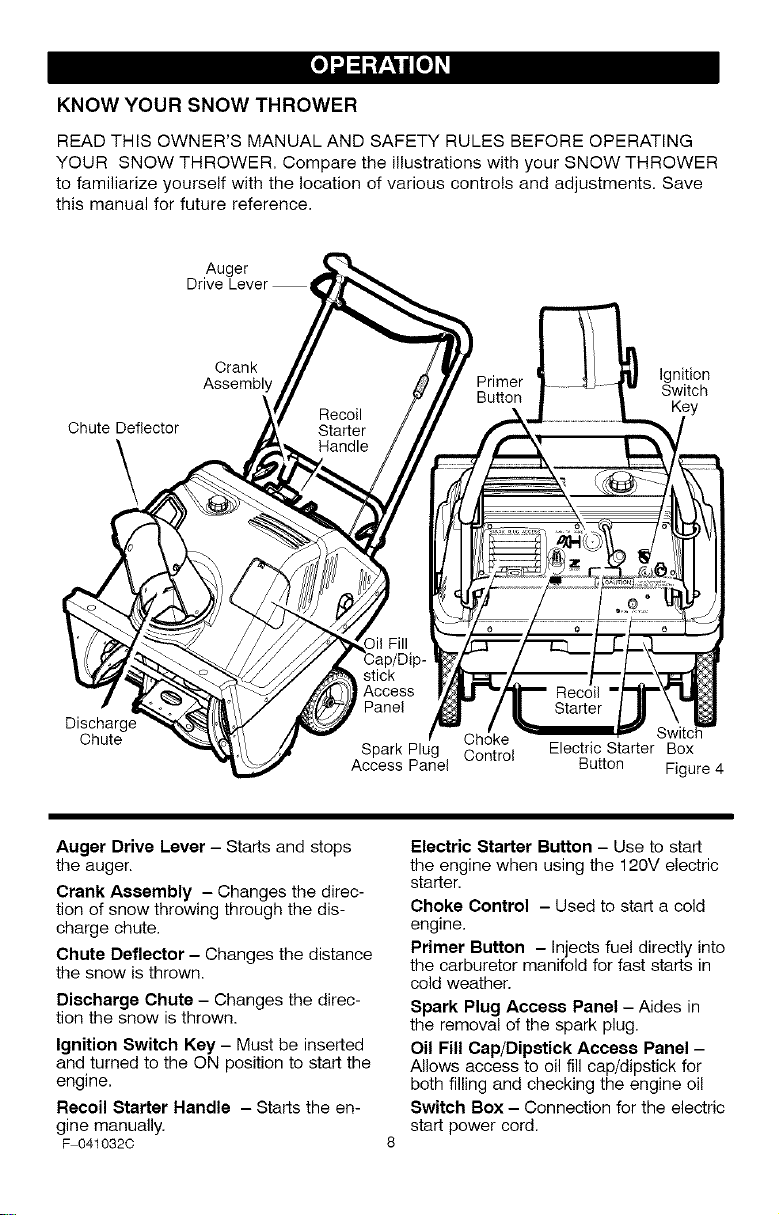
KNOW YOUR SNOW THROWER
READ THIS OWNER'S MANUAL AND SAFETY RULES BEFORE OPERATING
YOUR SNOW THROWER. Compare the illustrations with your SNOW THROWER
to familiarize yourself with the location of various controls and adjustments. Save
this manual for future reference.
Auger
Drive Lever
Chute Deflector
\
Crank Ignition
Assembly Primer Switch
Key
Discharge
Chute
stick
Access
Panel
Choke
Spark Plug Control Electric Starter Box
Access Panel Button Figure 4
Auger Drive Lever - Starts and stops
the auger.
Crank Assembly - Changes the direc-
tion of snow throwing through the dis-
charge chute,
Chute Deflector - Changes the distance
the snow is thrown.
Discharge Chute - Changes the direc-
tion the snow is thrown.
Ignition Switch Key - Must be inserted
and turned to the ON position to start the
engine.
Recoil Starter Handle - Starts the en-
gine manually.
F 041032C
Electric Starter Button - Use to start
the engine when using the 120V electric
starter,
Choke Control - Used to start a cold
engine,
Primer Button - Injects fuel directly into
the carburetor manifold for fast starts in
cold weather.
Spark Plug Access Panel - Aides in
the removal of the spark plug,
Oil Fill Cap/Dipstick Access Panel -
Allows access to oil fill cap/dipstick for
both filling and checking the engine oil
Switch Box - Connection for the electric
start power cord.
[o_o)_l
,_ WARNING: Read Owner's
Manual before operating
machine. Never direct dis-
charge toward bystanders. Stop the
engine before unclogging discharge
chute or auger housing and before
leaving the machine.
TO STOP YOUR
SNOW THROWER
1. To stop throwing snow, release the
auger drive lever. See Figure 4.
NOTE: if the snow thrower contin-
ues to slowly move forward, see
"How To Adjust The Auger Control
Cable" in the Service And Adjust-
ment Section.
2. To stop the engine, move the igni-
tion switch key to the off position.
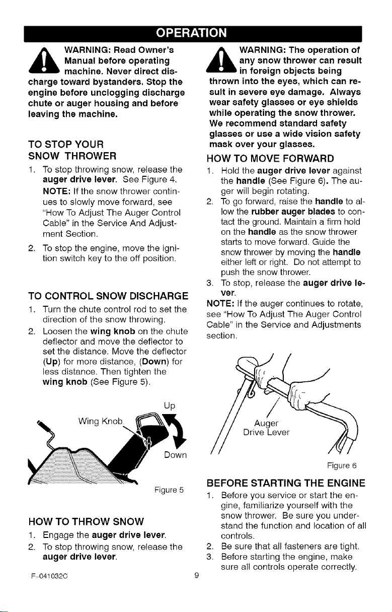
TO CONTROL SNOW DISCHARGE
1. Turn the chute control rod to set the
direction of the snow throwing.
2. Loosen the wing knob on the chute
deflector and move the deflector to
set the distance. Move the deflector
(Up) for more distance, (Down) for
less distance. Then tighten the
wing knob (See Figure 5).
Up
Wing Knob
Down
Figure 5
HOW TO THROW SNOW
1. Engage the auger drive lever.
2. To stop throwing snow, release the
auger drive lever.
F 041032C
,_ WARNING: The operation of
any snow thrower can result
in foreign objects being
thrown into the eyes, which can re-
sult in severe eye damage. Always
wear safety glasses or eye shields
while operating the snow thrower.
We recommend standard safety
glasses or use a wide vision safety
mask over your glasses.
HOW TO MOVE FORWARD
1. Hold the auger drive lever against
the handle (See Figure 6). The au-
ger will begin rotating.
2. To go forward, raise the handle to al-
low the rubber auger blades to con-
tact the ground. Maintain a firm hold
on the handle as the snow thrower
starts to move forward. Guide the
snow thrower by moving the handle
either left or right. Do not attempt to
push the snow thrower.
3. To stop, release the auger drive le-
ver.
NOTE: If the auger continues to rotate,
see "How To Adjust The Auger Control
Cable" in the Service and Adjustments
section.
Auger
Drive Lever
Figure 6
BEFORE STARTING THE ENGINE
1. Before you service or start the en-
gine, familiarize yourself with the
snow thrower. Be sure you under-
stand the function and location of all
controls.
2. Be sure that all fasteners are tight.
3. Before starting the engine, make
sure all controls operate correctly.
[o_o)_l
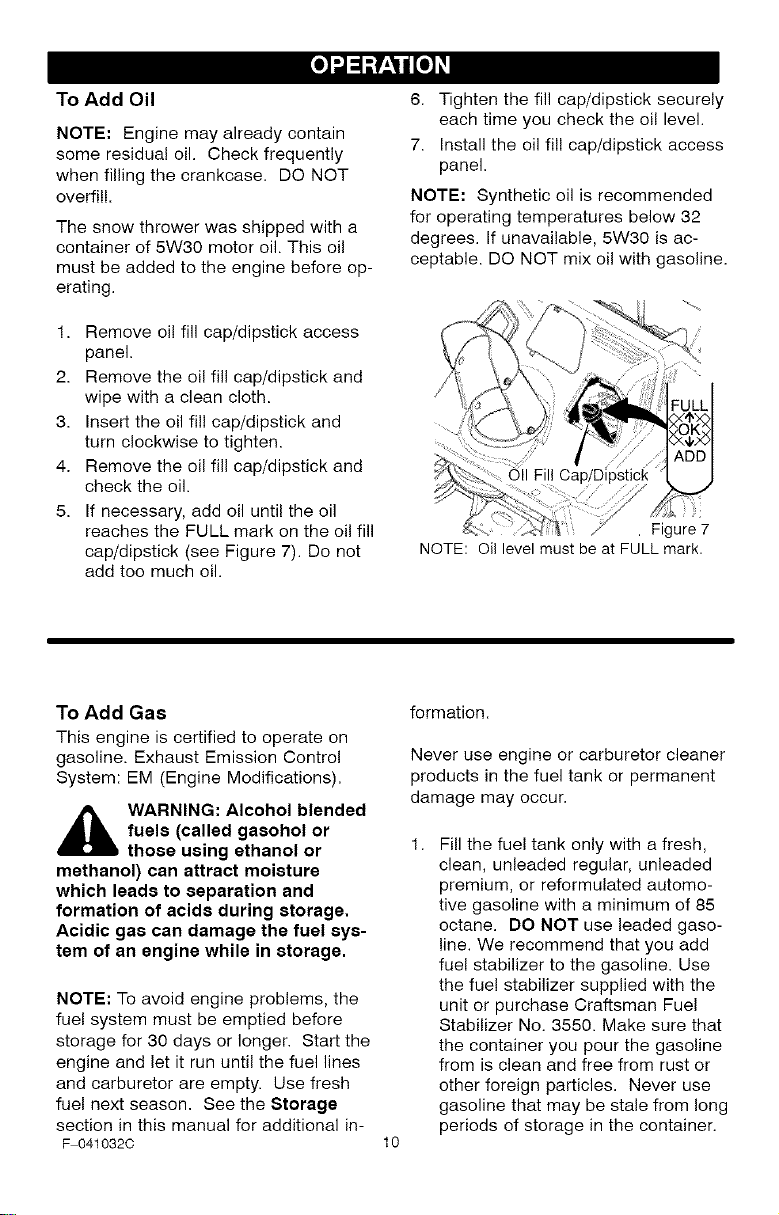
To Add Oil
NOTE: Engine may already contain
some residual oil. Check frequently
when filling the crankcase. DO NOT
overfil!.
The snow thrower was shipped with a
container of 5W30 motor oil. This oil
must be added to the engine before op-
erating.
1. Remove oil fill cap/dipstick access
panel.
2. Remove the oil fill cap/dipstick and
wipe with a clean cloth.
3. Insert the oil fil! cap/dipstick and
turn clockwise to tighten.
4. Remove the oil fill cap/dipstick and
check the oil.
5. If necessary, add oil until the oil
reaches the FULL mark on the oil fill
cap/dipstick (see Figure 7). Do not
add too much oil.
6. Tighten the fill cap/dipstick securely
each time you check the oil level.
7. Install the oil fil! cap/dipstick access
panel.
NOTE: Synthetic oil is recommended
for operating temperatures below 32
degrees. If unavailable, 5W30 is ac-
ceptable. DO NOT mix oil with gasoline.
i i
Fill
. Figure 7
NOTE: Oil level must be at FULL mark.
To Add Gas
This engine is certified to operate on
gasoline. Exhaust Emission Control
System: EM (Engine Modifications).
_b ARNING: Alcohol blended
fuels (called gaeohol or
those using ethanol or
methanol) can attract moisture
which leads to separation and
formation of acids during storage.
Acidic gas can damage the fuel sys-
tem of an engine while in storage.
NOTE: To avoid engine problems, the
fuel system must be emptied before
storage for 30 days or longer. Start the
engine and let it run until the fuel lines
and carburetor are empty. Use fresh
fuel next season. See the Storage
section in this manual for additional in-
F 041032C
formation.
Never use engine or carburetor cleaner
products in the fuel tank or permanent
damage may occur.
10
Fill the fuel tank only with a fresh,
clean, unleaded regular, unleaded
premium, or reformulated automo-
tive gasoline with a minimum of 85
octane. DO NOT use leaded gaso-
line. We recommend that you add
fuel stabilizer to the gasoline. Use
the fue! stabilizer supplied with the
unit or purchase Craftsman Fuel
Stabilizer No. 3550. Make sure that
the container you pour the gasoline
from is clean and free from rust or
other foreign particles. Never use
gasoline that may be stale from long
periods of storage in the container.
[o_o)_l
,_ WARNING: Gasoline is flam-
mable. Always use caution
when handling or storing
gasoline.
• Turn engine off and let engine
cool at least two minutes before
removing the gas cap.
• Do not fill fuel tank while snow
thrower is running, when it is hot,
or when snow thrower is in an en-
closed area.
• Keep away from open flame or an
electrical spark and do not smoke
while filling the fuel tank.
• Never fill the tank completely. Fill
the tank to approximately 1-1/2"
below the top of the tank opening
to provide space for expansion of
fuel.
• Always fill fuel tank outdoors and
use a funnel or spout to prevent
spilling.
• Make sure to wipe up any spilled
fuel before stating the engine.
• Store gasoline in a clean, ap-
proved container and keep the
cap in place on the container.
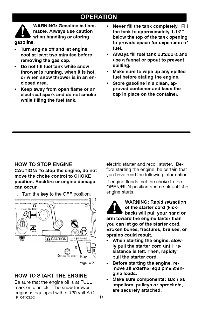
HOW TO STOP ENGINE
CAUTION: To stop the engine, do not
move the choke control to CHOKE
position. Backfire or engine damage
can occur.
1. Turn the key to the OFF position.
Figure 8
HOW TO START THE ENGINE
Be sure that the engine oil is at FULL
mark on dipstick. The snow thrower
engine is equipped with a 120 volt A.C.
F 041032C
electric starter and recoil starter. Be-
fore starting the engine, be certain that
you have read the following information.
If engine floods, set the choke to the
OPEN/RUN position and crank until the
engine starts.
,_ WARNING: Rapid retraction
of the starter cord (kick-
back) will pull your hand or
arm toward the engine faster than
you can let go of the starter cord.
Broken bones, fractures, bruises, or
sprains could result.
• When starting the engine, slow-
ly pull the starter cord until re-
sistance is felt. Then, rapidly
pull the starter cord.
• Before starting the engine, re-
move all external equipment/en-
gine loads.
• Make sure components; such as
impellors, pulleys or sprockets,
are securely attached.
[o_o)_l
,_ WARNING: The starter i8
equipped with a three-wire
power cord and plug and is
designed to operate on 120 volt AC
household current. It must be prop-
erly grounded at all times to avoid
the possibility of electrical shock
which may be injurious to operator.
• Follow all instructions carefully
as set forth in the "To Start En-
gine" section.
• Determine that your house wiring
is a three-wire grounded system.
Ask a licensed electrician if you
are not sure. If your house wire
system is not a three-wire system,
do not use this electric starter un-
der any conditions.
If your system is grounded and a
three-hole receptacle is not avail-
able at the point your starter will
normally be used, one should be
installed by a licensed electrician.
When connecting 120 volt AC
"Power Cord", always connect the
cord to the Switch Box on the en-
gine first, then plug the other end
into the three-hole grounded re-
ceptacle. When disconnecting
"Power Cord", always unplug the
end in the three-hole grounded re-
ceptacle first.
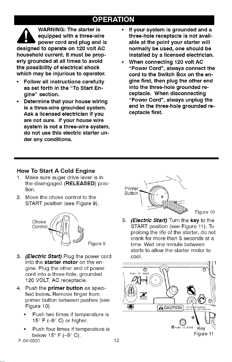
How To Start A Cold Engine
1. Make sure auger drive lever is in
the disengaged (RELEASED) posi-
tion.
2. Move the choke control to the
START position (see Figure 9).
Figure 9
3. (Electric Start) Plug the power cord
into the starter motor on the en-
gine. Plug the other end of power
cord into a three-hole, grounded
120 VOLT, AC receptacle.
4. Push the primer button as speci-
fied below. Remove finger from
primer button between pushes (see
Figure 10).
• Push two times if temperature is
15° F (-9 ° C) or higher.
• Push four times if temperature is
below 15° F (-9 ° C).
F 041032C
12
Primer
Button •
Figure 10
(Electric Start) Turn the key to the
START position (see Figure 11). To
prolong the life of the starter, do not
crank for more than 5 seconds at a
time. Wait one minute between
starts to allow the starter motor to
cool.
Figure 11
[o_o)_l
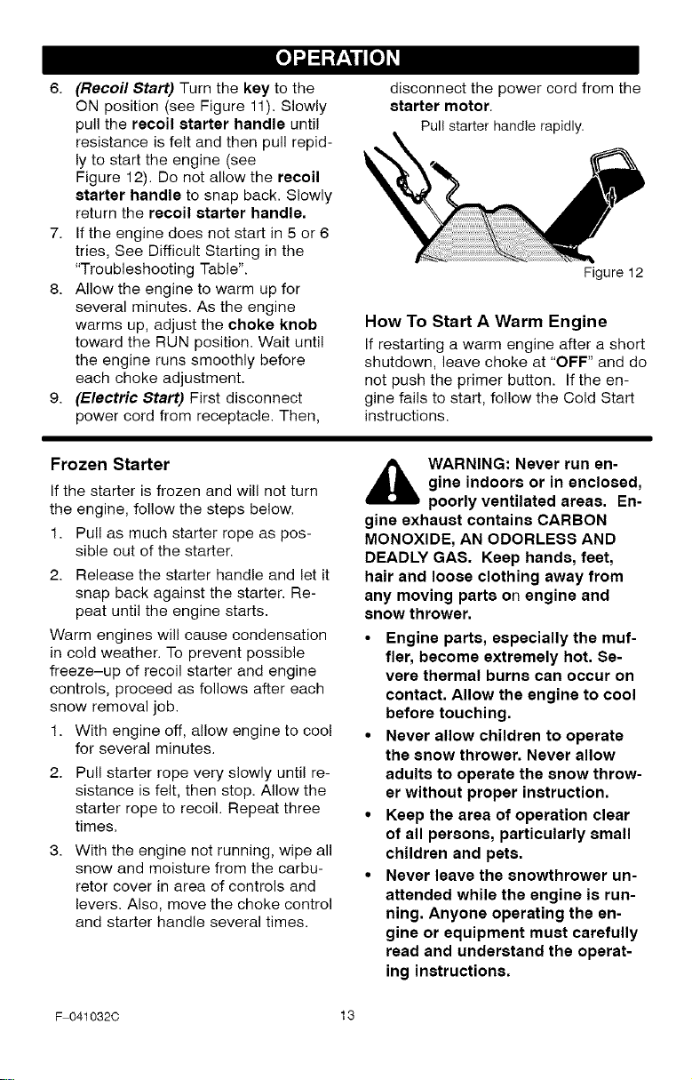
6. (Recoil Start) Turn the key to the
ON position (see Figure 11). Slowly
pull the recoil starter handle until
resistance is felt and then pull repid-
ly to start the engine (see
Figure 12). Do not allow the recoil
starter handle to snap back. Slowly
return the recoil starter handle,
7. Ifthe engine does not start in 5 or 6
tries, See Difficult Starting in the
"Troubleshooting Table".
8. Allow the engine to warm up for
several minutes. As the engine
warms up, adjust the choke knob
toward the RUN position. Wait until
the engine runs smoothly before
each choke adjustment.
9. (Electric Start) First disconnect
power cord from receptacle. Then,
disconnect the power cord from the
starter motor.
Pullstarter handle rapidly.
Figure 12
How To Start A Warm Engine
If restarting a warm engine after a short
shutdown, leave choke at "OFF" and do
not push the primer button. If the en-
gine fails to start, follow the Cold Start
instructions.
Frozen Starter
If the starter is frozen and will not turn
the engine, follow the steps below.
1. Pull as much starter rope as pos-
sible out of the starter.
2. Release the starter handle and let it
snap back against the starter. Re-
peat until the engine starts.
Warm engines will cause condensation
in cold weather. To prevent possible
freeze-up of recoil starter and engine
controls, proceed as follows after each
snow removal job.
1. With engine off, allow engine to coo!
for several minutes.
Pull starter rope very slowly until re-
sistance is felt, then stop. Allow the
starter rope to recoil. Repeat three
times.
With the engine not running, wipe all
snow and moisture from the carbu-
retor cover in area of controls and
levers. Also, move the choke control
and starter handle several times.
,_ WARNING: Never run en-
gine indoors or in enclosed,
poorly ventilated areas. En-
gine exhaust contains CARBON
MONOXIDE, AN ODORLESS AND
DEADLY GAS. Keep hands, feet,
hair and loose clothing away from
any moving parts on engine and
snow thrower.
• Engine parts, especially the muf-
fler, become extremely hot. Se-
vere thermal burns can occur on
contact. Allow the engine to cool
before touching.
• Never allow children to operate
the snow thrower. Never allow
adults to operate the snow throw-
er without proper instruction.
• Keep the area of operation clear
of all persons, particularly small
children and pets.
• Never leave the snowthrower un-
attended while the engine is run-
ning. Anyone operating the en-
gine or equipment must carefully
read and understand the operat-
ing instructions.
F 041032C 13
[o_o)_l
HOW TO REMOVE OBJECTS
FROM AUGER
_ ARNING" Do not attempt
to remove any item that may
become lodged in auger
without taking the following precau-
tions:
• Release auger drive lever.
• Rotate the ignition switch key to the
stop position to stop the engine.
• Disconnect spark plug wire.
• Do not place your hands in the au-
ger or discharge chute. Use a pry
bar.
SNOW THROWING TIPS
1. When the handle is raised, the au-
ger blades will engage the ground
and the snow thrower will move for-
ward. When the auger drive lever is
released, the auger blades will stop.
If the blades do not stop, see "How
To Adjust The Auger Drive Cable" in
the Service And Adjustment section.
2. Most efficient snow throwing is ac-
complished when the snow is re-
moved immediately after if falls.
3. For complete snow removal, slightly
overlap each previous path.
4. Whenever possible, discharge the
snow down wind.
5. The distance the snow will be dis-
charged can be adjusted by moving
the discharge chute deflector. Raise
the deflector for more distance or
lower the deflector for less distance.
6. In windy conditions, lower the chute
deflector to direct the discharged
snow close to the ground where it is
less likely to blow into unwanted
areas.
7. For safety and to prevent damage
to the snow thrower, keep the area
to be cleared free of stones, toys
and other foreign objects.
8. When clearing snow from crushed
rock or gravel driveways, do not al-
low the auger blades to contact the
driveway. Move the handle down to
slightly raise the auger blades.
9. The forward speed of the snow
thrower is dependent on the depth
and weight of the snow. Experience
will establish the most effective
method of using the snow thrower
under different conditions.
F 041032C
10. After each snow throwing job, allow
the engine to run for a few minutes.
The snow and accumulated ice wil!
melt off the engine.
11. Clean the snow thrower after each
use.
12. Remove ice, snow and debris from
the entire snow thrower. Flush with
water to remove all salt or other
chemicals. Wipe snow thrower dry.
DRY AND AVERAGE SNOW
1. Snow up to eight inches deep can
be removed rapidly and easily by
walking at a moderate rate. For
snow or drifts of a greater depth,
slow your pace to allow the dis-
charge chute to dispose of the snow
as rapidly as the auger receives the
snow.
2. Plan to have the snow discharged in
the direction the wind is blowing.
WET PACKED SNOW
Move slowly into wet, packed snow. if
the wet, packed snow causes the auger
to slow down or the discharge chute be-
gins to clog, back off and begin a series
of short back and forth jabs into the
snow. These short back and forth jabs,
four to six inches, will "belch" the snow
from the chute.
14
SNOW BANKS AND DRIFTS
In snow of greater depth than the unit,
use the same "jabbing" technique de-
scribed above. Turn the discharge
chute away from the snow bank. More
time will be required to remove snow of
this type than leve! snow.
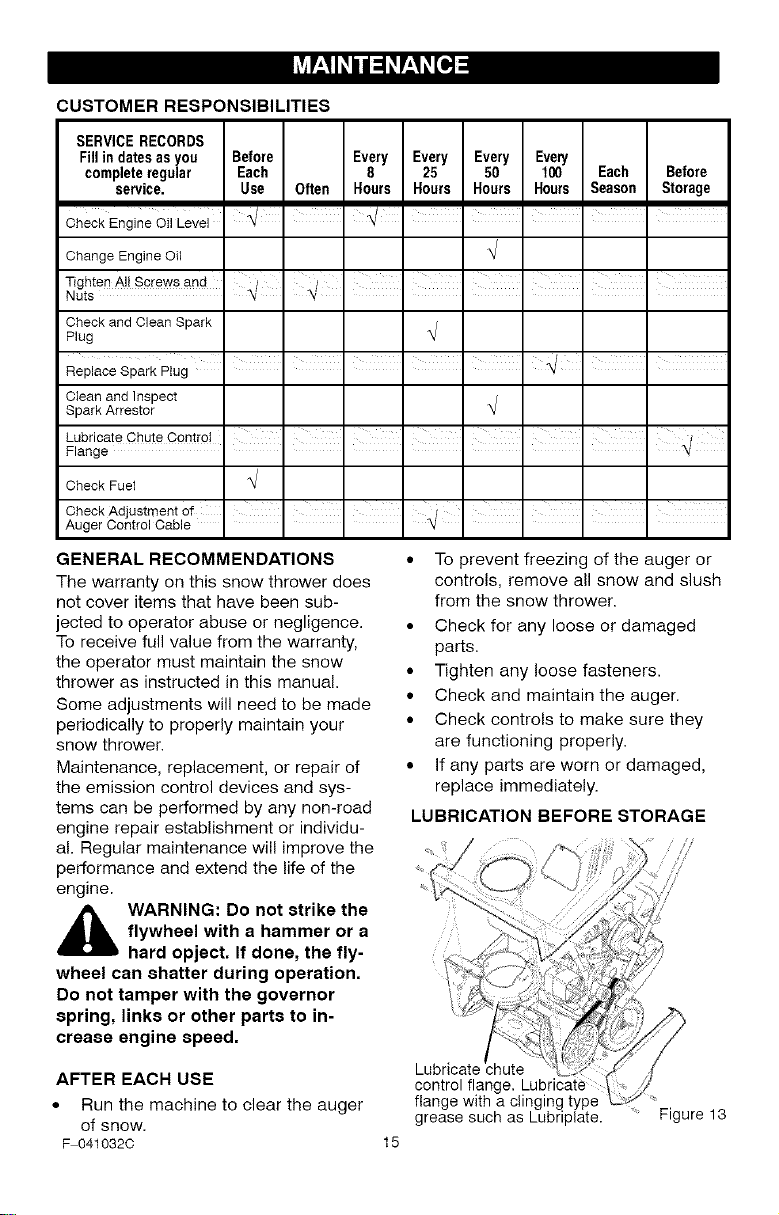
CUSTOMER RESPONSIBILITIES
SERVICERECORDS
Fill in dates asyou Before Every Every Every Every
completeregular Each 8 25 50 100 Each Before
service. Use Often Hours Hours Hours Hours Season Storage
Change EngineOil
Tighten All Sprewsand
Nuts
CheckandClean Spark
Plug
Cleanand Inspect
SparkArrestor
Check Fuel
Check Adjustment of I I I _/ ' I I I
Auger ControlCable " _t
GENERAL RECOMMENDATIONS
The warranty on this snow thrower does
not cover items that have been sub-
jected to operator abuse or negligence.
To receive full value from the warranty,
the operator must maintain the snow
thrower as instructed in this manual.
Some adjustments will need to be made
periodically to properly maintain your
snow thrower.
Maintenance, replacement, or repair of
the emission control devices and sys-
tems can be performed by any non-road
engine repair establishment or individu-
al. Regular maintenance will improve the
performance and extend the life of the
engine.
,_ WARNING: Do not strike the
flywheel with a hammer or a
hard opject. If done, the fly-
wheel can shatter during operation.
Do not tamper with the governor
spring, links or other parts to in-
crease engine speed.
• To prevent freezing of the auger or
controls, remove all snow and slush
from the snow thrower.
• Check for any loose or damaged
parts.
• Tighten any loose fasteners.
• Check and maintain the auger.
• Check controls to make sure they
are functioning properly.
• If any parts are worn or damaged,
replace immediately.
LUBRICATION BEFORE STORAGE
AFTER EACH USE
• Run the machine to clear the auger
of snow.
F 0410320
control flange.
flange with a clinging type
grease such as Lubriplate. Figure 13
15
ENGINE SPECIFICATIONS
HORSEPOWER 5 HP
DISPLACEMENT 148 cc
BORE 65mm (2.562 in.)
STROKE 45mm (1.750 in.)
GASOLINE 2 quarts (85 octane
CAPACITY leaded)
OIL CAPACITY 5W30
(18 oz capacity)
SPARK PLUG: Champion RJ19LM
(Gap .030 in.) or
equivalent
VALVE Intake: 0.005 0.007 in.
CLEARANCE: Exhaust: 0.007 0.009 in.
ARMATURE
AIR GAP: 0.006 0.010 in.
POWER RATINGS
The power ratings for an individual
engine model are initially developed by
starting with SAE (Society of Automo-
tive Engineers) code J1940 (Small
Engine Power & Torque Rating Proce-
dure) (Revision 2002-05). Given both
the wide array of products on which our
engines are placed, and the variety of
environmental issues applicable to
operating the equipment, it may be that
the engine you have purchased will not
develop the rated horsepower when
used in a piece of power equipment
(actual "on-site" power). This difference
is due to a variety of factors including,
but not limited to, the following: differ-
ences in altitude, temperature, baro-
metric pressure, humidity, fuel, engine
lubrication, maximum governed engine
speed, individual engine to engine
variability, design of the particular piece
of power equipment, the manner in
which the engine is operated, engine
run-in to reduce friction and clean out of
combustion chambers, adjustments to
the valves and carburetor, and other
factors. The power ratings may also be
adjusted based on comparisons to
other similar engines utilized in similar
applications, and will therefore not
necessarily match the values derived
using the foregoing codes.
SNOW THROWER
ENGINE
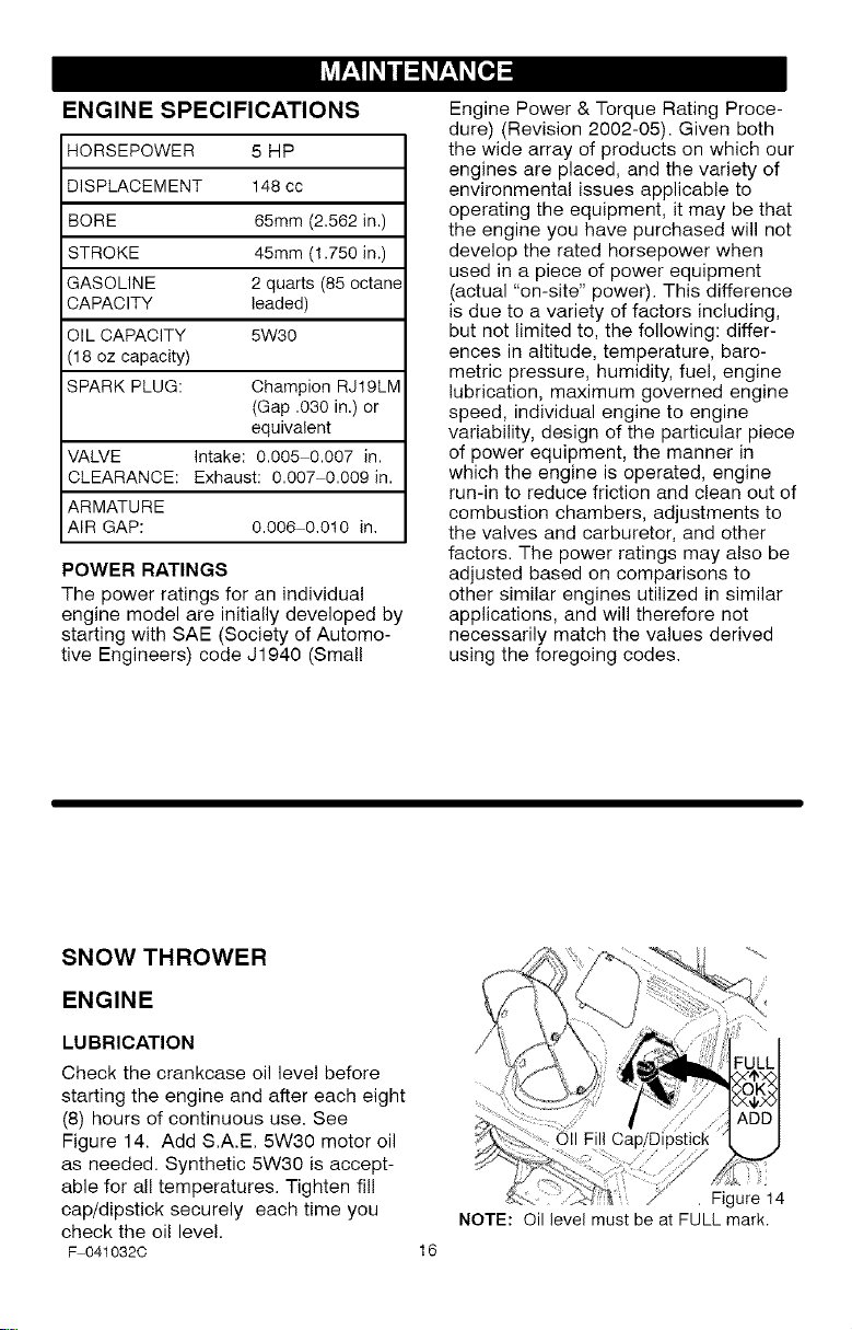
LUBRICATION
Check the crankcase oil level before
starting the engine and after each eight
(8) hours of continuous use. See
Figure 14. Add S.A.E. 5W30 motor oil
as needed. Synthetic 5W30 is accept-
able for all temperatures, Tighten fill
cap/dipstick securely each time you
check the oil leve!.
F 041032C
16
Ca
. Figure 14
NOTE: Oil level must be at FULL mark.
Change the oil every fifty (50) hours or
at least once a year if the snow thrower
is not used for fifty (50) hours.
"To Add Oil" in the Operation Sec-
tion.
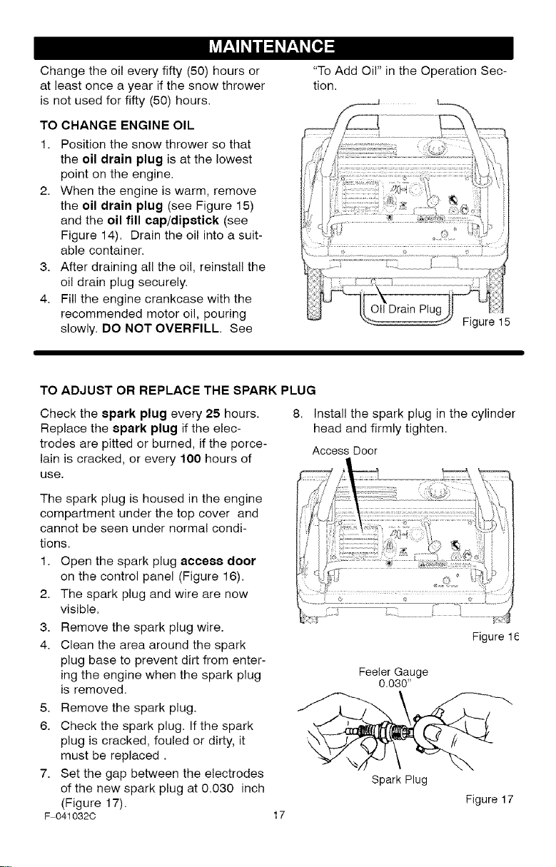
TO CHANGE ENGINE OIL
1. Position the snow thrower so that
the oil drain plug is at the lowest
point on the engine.
2. When the engine is warm, remove
the oil drain plug (see Figure 15)
and the oil fill cap/dipstick (see
Figure 14). Drain the oil into a suit-
able container.
3. After draining all the off, reinstall the
oil drain plug securely.
4. Fill the engine crankcase with the
recommended motor oil, pouring
slowly. DO NOT OVERFILL. See
Figure 15
TO ADJUST OR REPLACE THE SPARK PLUG
Check the spark plug every 25 hours.
Replace the spark plug if the elec-
trodes are pitted or burned, if the porce-
lain is cracked, or every 100 hours of
use.
The spark plug is housed in the engine
compartment under the top cover and
cannot be seen under normal condi-
tions.
1. Open the spark plug access door
on the control panel (Figure 16).
2. The spark plug and wire are now
visible.
3. Remove the spark plug wire.
4. Clean the area around the spark
plug base to prevent dirt from enter-
ing the engine when the spark plug
is removed.
5. Remove the spark plug.
6. Check the spark plug. If the spark
plug is cracked, fouled or dirty, it
must be replaced.
7. Set the gap between the electrodes
of the new spark plug at 0.030 inch
(Figure 17).
F 041032C
17
Install the spark plug in the cylinder
head and firmly tighten.
Access Door
Figure 1
Feeler Gauge
0.030"
Spark Plug
Figure 17
,_ WARNING: To prevent acci-
dental starting when making
any adjustments or repairs,
always disconnect the spark plug
wire and place it where it cannot
make contact with the spark plug.
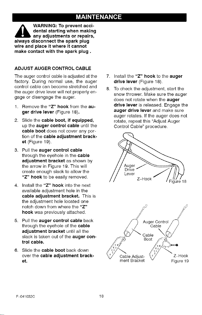
ADJUST AUGER CONTROL CABLE
The auger control cable is adjusted at the 7.
factory. During normal use, the auger
control cable can become stretched and 8.
the auger drive lever will not properly en-
gage or disengage the auger.
1. Remove the "Z" hook from the au-
ger drive lever (Figure 18).
2. Slide the cable boot, if equipped,
up the auger control cable until the
cable boot does not cover any por-
tion of the cable adjustment brack-
et (Figure 19).
3. Pull the auger control cable
through the eyehole in the cable
adjustment bracket as shown by
the arrow in Figure 19. This will
create enough slack to allow the
"Z" hook to be easily removed.
4. Install the "Z" hook into the next
available adjustment hole in the
cable adjustment bracket. This is
the adjustment hole located one
notch down from where the "Z"
hook was previously attached.
5. Pull the auger control cable back
through the eyehole of the cable
adjustment bracket until all the
slack is taken out of the auger con-
trol cable.
6. Slide the cable boot back down
over the cable adjustment brack-
et.
Install the "Z" hook to the auger
drive lever (Figure 18).
To check the adjustment, start the
snow thrower. Make sure the auger
does not rotate when the auger
drive lever is released. Engage the
auger drive lever and make sure
auger rotates, if the auger does not
rotate, repeat this "Adjust Auger
Control Cable" procedure.
Auger
Drive
Lever
Z Hook
Figure 18
Auger Control
Cable
Cable
Boot
Cable Adjust-
ment Bracket
_Hook
Figure 19
F 041032C 18
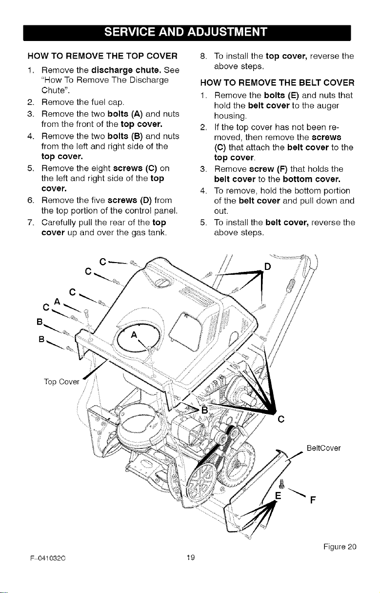
HOW TO REMOVE THE TOP COVER
1. Remove the discharge chute. See
"How To Remove The Discharge
Chute".
2. Remove the fuel cap.
3. Remove the two bolts (A) and nuts
from the front of the top cover.
4. Remove the two bolts (B) and nuts
from the left and right side of the
top cover.
5. Remove the eight screws (C) on
the left and right side of the top
cover.
6. Remove the five screws (D) from
the top portion of the control panel,
7. Carefully pull the rear of the top
cover up and over the gas tank.
8. To install the top cover, reverse the
above steps.
HOW TO REMOVE THE BELT COVER
1. Remove the bolts (E) and nuts that
hold the belt cover to the auger
housing.
2. If the top cover has not been re-
moved, then remove the screws
(C) that attach the belt cover to the
top cover.
3. Remove screw (F) that holds the
belt cover to the bottom cover.
4. To remove, hold the bottom portion
of the belt cover and pull down and
out.
5. To install the belt cover, reverse the
above steps.
Top
C
BeltOover
F
Figure 20
F 0410320 19
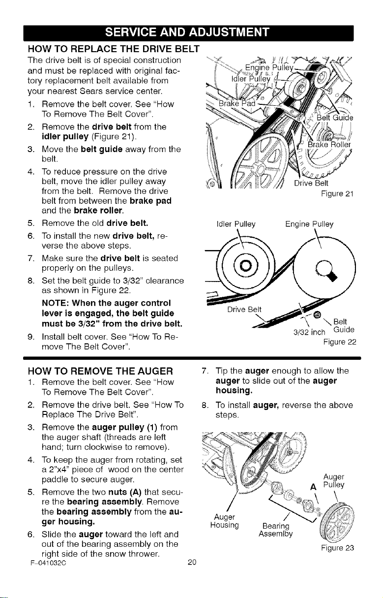
HOWTO REPLACE THE DRIVE BELT
The drive belt is of special construction
and must be replaced with original fac-
tory replacement belt available from
your nearest Sears service center.
1. Remove the belt cover. See "How
To Remove The Belt Cover".
2. Remove the drive belt from the
idler pulley (Figure 21).
3. Move the belt guide away from the
belt.
4. To reduce pressure on the drive
belt, move the idler pulley away
from the belt. Remove the drive
belt from between the brake pad
and the brake roller,
5. Remove the old drive belt,
6. To install the new drive belt, re-
verse the above steps.
7. Make sure the drive belt is seated
properly on the pulleys.
8. Set the belt guide to 3/32" clearance
as shown in Figure 22.
NOTE: When the auger control
lever is engaged, the belt guide
must be 3/32" from the drive belt.
9. Install belt cover. See "How To Re-
move The Belt Cover".
Belt Guide
Brake Roller
Drive Belt
Figure 21
Idler Pulley Engine Pulley
_pr\ _, Belt
3/32 inch Guide
Figure 22
HOW TO REMOVE THE AUGER
1. Remove the belt cover. See "How
To Remove The Belt Cover".
2. Remove the drive belt. See "How To
Replace The Drive Belt".
3. Remove the auger pulley (1) from
the auger shaft (threads are left
hand; turn clockwise to remove).
4. To keep the auger from rotating, set
a 2"x4" piece of wood on the center
paddle to secure auger.
5. Remove the two nuts (A) that secu-
re the bearing assembly. Remove
the bearing assembly from the au-
ger housing.
6. Slide the auger toward the left and
out of the bearing assembly on the
right side of the snow thrower.
F 041032C
2O
Tip the auger enough to allow the
auger to slide out of the auger
housing.
To install auger, reverse the above
steps.
Auger
Housing
Bearing
Assemlby
Auger
A Pulley
\
Figure 23
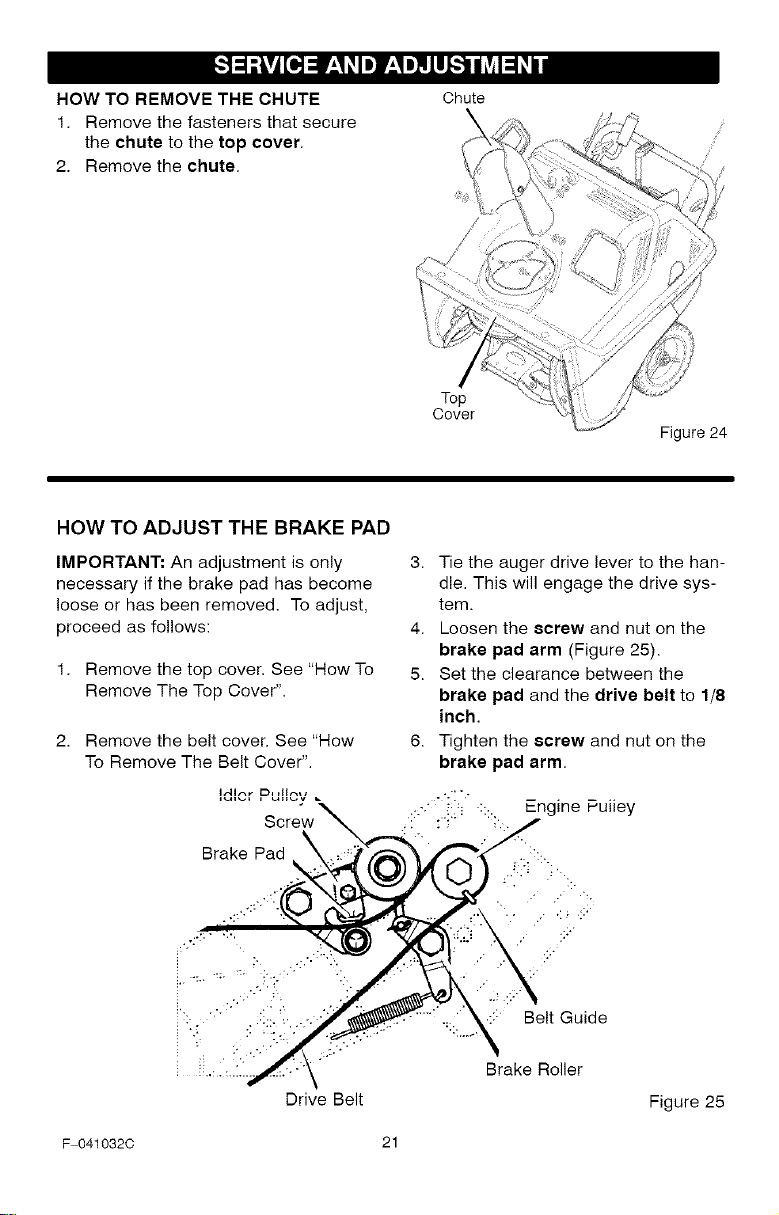
HOW TO REMOVE THE CHUTE
1. Remove the fasteners that secure
the chute to the top cover.
2. Remove the chute.
Chute
Top
Cover
Figure 24
HOW TO ADJUST THE BRAKE PAD
IMPORTANT: An adjustment is only
necessary if the brake pad has become
loose or has been removed. To adjust,
proceed as follows:
1. Remove the top cover. See "How To
Remove The Top Cover".
2. Remove the belt cover. See "How
To Remove The Belt Cover".
Brake Pad
Drive Belt
3. Tie the auger drive lever to the han-
dle. This will engage the drive sys-
tem.
4. Loosen the screw and nut on the
brake pad arm (Figure 25).
5. Set the clearance between the
brake pad and the drive belt to 1/8
inch.
6. Tighten the screw and nut on the
brake pad arm.
::: Belt Guide
Brake Roller
Figure 25
F 041032C 21
_ WARNING: Never store your
snow thrower with gasoline
in the fuel tank indoors or in
an enclosed, poorly ventilated area.
If gasoline remains in the tank,
fumes may reach an open flame,
spark or pilot light from a furnace,
water heater, clothes dryer, ciga-
rette, etc.
To prevent damage (if snow thrower is
not used for more than 30 days) follow
the steps below.
SNOW THROWER
1. Thoroughly clean the snow thrower.
2. Lubricate all lubrication points. See
the Maintenance section.
3. Be sure that all nuts, bolts and
screws are securely fastened. In-
spect all visible moving parts for
damage, breakage and wear. Re-
place if necessary.
4. Touch up all rusted or chipped paint
surfaces; sand lightly before paint-
ing.
5. Cover the bare metal parts of the
blower housing auger and the im-
peller with rust preventative, such
as a spray lubricant.
NOTE: A yearly checkup or tune-up by
a Sears service center is a good way of
ensuring that your snow thrower will
provide maximum performance for the
next season.
ENGINE
Gasoline must be removed or treated to
prevent gum deposits from forming in
the fuel tank, filter, hose, and carburetor
during storage. Also, during storage al-
cohol blended gasoline that uses etha-
nol or methanol (sometimes called
gasohol) attracts water. It acts on the
gasoline to form acids which damage
the engine.
1. Run the engine until the fuel tank is
empty and the engine stops.
2. If you do not remove the gasoline,
use fuel stabilizer supplied with unit
or purchase Craftsman Fuel Stabi-
lizer No. 3550. Add fuel stabilizer to
any gasoline left in the tank to mini-
mize gum deposits and acids. If the
fue! tank is almost empty, mix stabi-
lizer with fresh gasoline in a sepa-
rate container and add some to the
fuel tank.
3. Always follow the instructions on the
stabilizer container. After the stabi-
lizer is added to the fuel tank, run
the engine at least ten minutes to
allow the mixture to reach the car-
buretor.
4. Change the engine oil.
5. Remove the spark plug and pour
about 15 ml (1/2 oz) of engine oil
into the cylinder. Replace the spark
plug and crank slowly to distribute
the oil.
6. Store in a clean and dry area, but
NOT near a stove, furnace or water
heater which uses a pilot light or
any device that can create a spark.
OTHER
1. If possible, store your snow thrower
indoors and cover it to give protec-
tion from dust and dirt.
2. If the snow thrower must be stored
outdoors, put the snow thrower on
blocks to raise it off of the ground.
3. Cover the snow thrower with a suit-
able protective cover that does not
retain moisture. Do not use plastic.
IMPORTANT: Never cover snow
thrower while engine and exhaust areas
are still warm.
F 041032C 22

_ol_]_ln_]:[oIo_il_[_
TROUBLE CORRECTION
Difficult starting Replace spark plug.
Drain and clean the fuel tank.
Refill with fresh fuel mixture.
Engine runs erratically Clean fuel line; check fuel
supply; add fresh fuel
mixture.
Engine stalls Set choke lever to run or off
position.
Engine runs erratically; Drain and clean the fuel tank.
Loss of power Refill with fresh fuel mixture.
Excessive vibration
Unit fails to propel itself
CAUSE
Defective spark plug.
Water or dirt in fuel system.
Blocked fuel line, empty gas
tank, or stale fuel mixture.
Unit running on CHOKE.
Water or dirt in fuel system.
Damaged auger assembly
Loose parts. Damaged
_mpeller.
Drive belt loose or damaged.
Incorrect adjustment of auger
drive cable
Repair or replace the auger
assembly.
Unit fails to discharge
snow
Immediately stop engine.
Remove ignition key. Tighten
all fasteners and make all
necessary repairs. If
vibration continues, take the
unit to a Sears service
center.
Replace drive belt.
Adjust auger drive cable.
Auger drive belt loose or Adjust auger drive belt;
damaged, replace if damaged.
Auger control cable not Adjust auger control cable.
adjusted correctly.
Discharge chute clogged. Stop engine immediately and
disconnect spark plug wire.
Clean discharge chute and
inside of auger housing.
Foreign object lodged in
auger
Stop engine immediately and
disconnect spark plug wire.
Remove object from auger.
F 041032C 23
(This page applicable in the U.S.A. and Canada only.)
Sears, Roebuck and Co., U.S.A. (Sears), the California Air Resources Board
(CARB) and the United States Environmental Protection Agency (U.S. EPA)
Emission Control System Warranty Statement (Owner's Defect Warranty
Rights and Obligations)
EMISSION CONTROL WARRANTY COVERAGE IS APPLICABLE TO CERTIFIED
ENGINES PURCHASED IN CALIFORNIA IN 1995 AND THEREAFTER, WHICH ARE
USED IN CALIFORNIA, AND TO CERTIFIED MODEL YEAR 1997 AND LATER EN-
GINES WHICH ARE PURCHASED AND USED ELSEWHERE IN THE UNITED
STATES (AND AFTER JANUARY 1, 2001 IN CANADA).
California and United States Emission Control Defects Warranty Statement
The California Air Resources Board
(CARB), U.S. EPA and Sears are pleased
to explain the Emission Control System
Warranty on your model year 2000 and lat-
er small off-road engine (SORE). In Califor-
nia, new small off-road engines must be
designed, built and equipped to meet the
State's stringent anti-smog standards.
Elsewhere in the United States, new non-
road, spark-ignition engines certified for
model year 1997 and later must meet simi-
lar standards set forth by the U.S. EPA.
Sears must warrant the emission control
system on your engine for the periods of
time listed below, provided there has been
no abuse, neglect or improper mainte-
nance of your small off-road engine.
Your emission control system includes
parts such as the carburetor, air cleaner,
ignition system, muffler and catalytic con-
verter. Also included may be connectors
and other emission related assemblies.
Where a warrantable condition exists,
Sears will repair your small off-road en-
gine at no cost to you including diagnosis,
parts and labor.
Sears Emission Control Defects Warranty Coverage
Small off-road engines are warranted rel- sions set forth below. If any covered part
ative to emission control parts defects for on your engine is defective, the part will
a period of two years, subject to provi- be repaired or replaced by Sears.
Owner's Warranty Responsibilities
As the small off-road engine owner, you
are responsible for the performance of
the required maintenance listed in your
Operating and Maintenance Instructions.
Sears recommends that you retain all
your receipts covering maintenance on
your small off-road engine, but Sears
cannot deny warranty solely for the lack
of receipts or for your failure to ensure the
performance of all scheduled mainte-
nance.
As the small off-road engine owner, you
should however be aware that Sears may
deny you warranty coverage if your small
off-road engine or a part has failed due to
abuse, neglect, improper maintenance or
unapproved modifications.
You are responsible for presenting your
small off-road engine to an Authorized
Sears Service Dealer as soon as a prob-
lem exists. The undisputed warranty re-
pairs should be completed in a
reasonable amount of time, not to exceed
30 days.
If you have any questions regarding your
warranty rights and responsibilities, you
should contact a Sears Service Repre-
sentative at 1-800-4694663.
The emission warranty is a defects war-
ranty. Defects are judged on normal en-
gine performance. The warranty is not
related to an in-use emission test.
F 041032C 24
Sears Emission Control Defects Warranty Provisions
The following are specific provisions relative to your Emission Control Defects Warranty
Coverage. It is in addition to the Sears engine warranty for non-regulated engines found
in the Operating and Maintenance Instructions.
1. Warranted Parts
Coverage under this warranty ex-
tends only to the parts listed below
(the emission control systems
parts) to the extent these parts
were present on the engine pur-
chased.
a. Fuel Metering System
• Cold start enrichment sys- 4.
tem
• Carburetor and internal
parts
• Fuel Pump
b. Air Induction System
• Air cleaner
• Intake manifold
c. Ignition System
• Spark plug(s)
• Magneto ignition system
d. Catalyst System
• Catalytic converter
5.
• Exhaust manifold
• Air injection system or
pulse valve
e. Miscellaneous Items Used in
Above Systems
• Vacuum, temperature,
position, time sensitive valves
and switches
• Connectors and assem-
blies
2. Length of Coverage
Sears warrants to the initial owner
and each subsequent purchaser that
the Warranted Parts shall be free
from defects in materials and work-
manship which caused the failure of
the Warranted Parts for a period of
two years from the date the engine
is delivered to a retail purchaser.
3. No Charge
Repair or replacement of any War- 6.
ranted Part will be performed at no
charge to the owner, including diag-
nostic labor which leads to the deter-
mination that a Warranted Part is
defective, if the diagnostic work is per-
formed at an Authorized Sears Ser-
vice Dealer. For emissions warranty
service contact your nearest Autho-
rized Sears Service Dealer as listed in
the '_ellow Pages" under "Engines,
Gasoline," "Gasoline Engines," "Lawn
Mowers," or similar category.
Claims and Coverage Exclusions
Warranty claims shall be filed in ac-
cordance with the provisions of the
Sears Engine Warranty Policy. War-
ranty coverage shall be excluded
for failures of Warranted Parts
which are not original Sears parts
or because of abuse, neglect or im-
proper maintenance as set forth in
the Sears Engine Warranty Policy.
Sears is not liable to cover failures
of Warranted Parts caused by the
use of add-on, non-original, or mo-
dified parts.
Maintenance
Any Warranted Part which is not
scheduled for replacement as re-
quired maintenance or which is
scheduled only for regular inspection
to the effect of "repair or replace as
necessary" shall be warranted as to
defects for the warranty period. Any
Warranted Part which is scheduled
for replacement as required mainte-
nance shall be warranted as to de-
fects only for the period of time up to
the first scheduled replacement for
that part. Any replacement part that
is equivalent in performance and du-
rability may be used in the perfor-
mance of any maintenance or
repairs. The owner is responsible for
the performance of all required main-
tenance, as defined in the Sears Op-
erating and Maintenance Instructions.
Consequential Coverage
Coverage hereunder shall extend to
the failure of any engine compo-
nents caused by the failure of any
Warranted Part still under warranty.
In the USA and Canada, a 24 hour hot line, 1-800-469-4663, has a menu of pre-re-
corded messages offering you engine maintenance information.
F 0410320 25
Look For Relevant Emissions Durability Period and Air
Index Information On Your Engine Emissions Label
Engines that are certified to meet the California Air Resources Board (CARB) Tier 2
Emission Standards must display information regarding the Emissions Durability Pe-
riod and the Air Index. Sears, Roebuck and Co., U.S.A. makes this information avail-
able to the consumer on our emission labels.
The Emissions Durability Period describes the number of hours of actual running
time for which the engine is certified to be emissions compliant, assuming proper
maintenance in accordance with the Operating & Maintenance Instructions. The fol-
lowing categories are used:
Moderate: Engine is certified to be emission compliant for 125 hours of actual
engine running time.
Intermediate: Engine is certified to be emission compliant for 250 hours of actual
engine running time.
Extended: Engine is certified to be emission compliant for 500 hours of actual
engine running time.
For example, a typical walk-behind lawn mower is used 20 to 25 hours per year.
Therefore, the Emissions Durability Period of an engine with an intermediate
rating would equate to 10 to 12 years.
The Air Index is a calculated number describing the relative level of emissions for a
specific engine family. The lower the Air Index, the cleaner the engine. This informa-
tion is displayed in graphical form on the emissions labe!.
After July 1, 2000, Look For Emissions Compliance
Period OnEngine Emissions Compliance Label
After July 1, 2000 certain Sears, Roebuck and Co., U.S.A. engines will be certified to
meet the United States Environmental Protection Agency (USEPA) Phase 2 emission
standards. For Phase 2 certified engines, the Emissions Compliance Period referred to
on the Emissions Compliance label indicates the number of operating hours for which the
engine has been shown to meet Federal emission requirements. For engines less than
225 cc displacement, Category C = 125 hours, B = 250 hours and A = 500 hours. For
engines of 225 cc or more, Category C = 250 hours, B = 500 hours and A = 1000 hours.
The displacement engines of Model Series 90000 is 148 cc.
The displacement engines of Model Series 120000 is 206 cc.
The displacement engines of Model Series 200000 is 305 cc.
The displacement engines of Model Series 210000 is 342 cc.
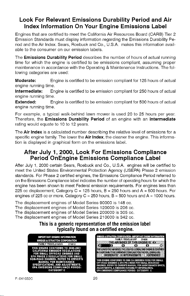
This is a generic representation ofthe emission label
typically found on a certified engine.
FAMILY YBSXSJ192VA 274812
F 041032C 26

F041032C 27
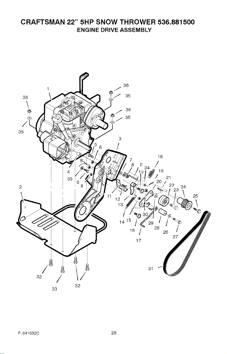
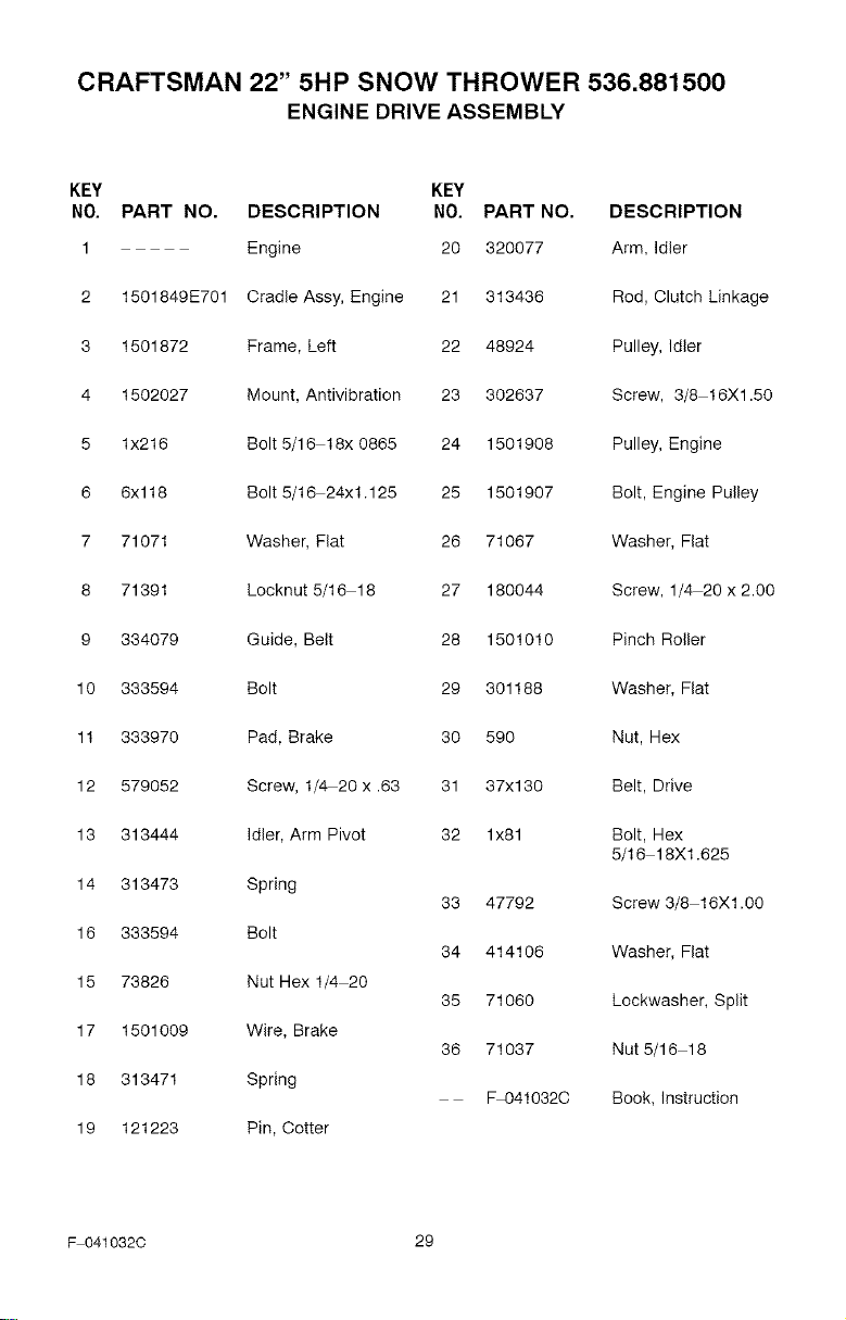
CRAFTSMAN 22" 5HP SNOW THROWER 536.881500
ENGINE DRIVE ASSEMBLY
F 041032C 28
CRAFTSMAN 22" 5HP SNOW THROWER 536.881500
ENGINE DRIVE ASSEMBLY
KEY KEY
NO. PART NO, DESCRIPTION NO. PART NO, DESCRIPTION
1 Engine 20 320077 Arm, Idler
2 1501849E701 Cradle Assy, Engine 21 313436 Rod, Clutch Linkage
3 1501872 Frame, Left 22 48924 Pulley, Idler
4 1502027 Mount, Antivibration 23 302637 Screw, 3/8 16Xl .50
5 lx216 Bolt 5/16 18x 0865 24 1501908 Pulley, Engine
6 6x118 Bolt 5/16 24x1.125 25 1501907 Bolt, Engine Pulley
7 71071 Washer, Fiat 26 71067 Washer, Fiat
8 71391 Locknut 5/16 18 27 180044 Screw, 1/4 20 x 2.00
9 334079 Guide, Belt 28 1501010 Pinch Relier
10 333594 Bolt 29 301188 Washer, Fiat
11 333970 Pad, Brake 30 590 Nut, Hex
12 579052 Screw, 1/4 20 x .63 31 37x130 Belt, Drive
13 313444 Idler, Arm Pivot 32 lx81 Bolt, Hex
5/16 18Xl.625
14 313473 Spring
33 47792 Screw 3/8 16Xl .00
16 333594 Bolt
34 414106 Washer, Fiat
15 73826 Nut Hex 1/4 20
35 71060 Lockwasher, Split
17 1501009 Wire, Brake
36 71037 Nut 5/16 18
18 313471 Spring
Fq3410320 Book, Instruction
19 121223 Pin, Cotter
F 041032C 29
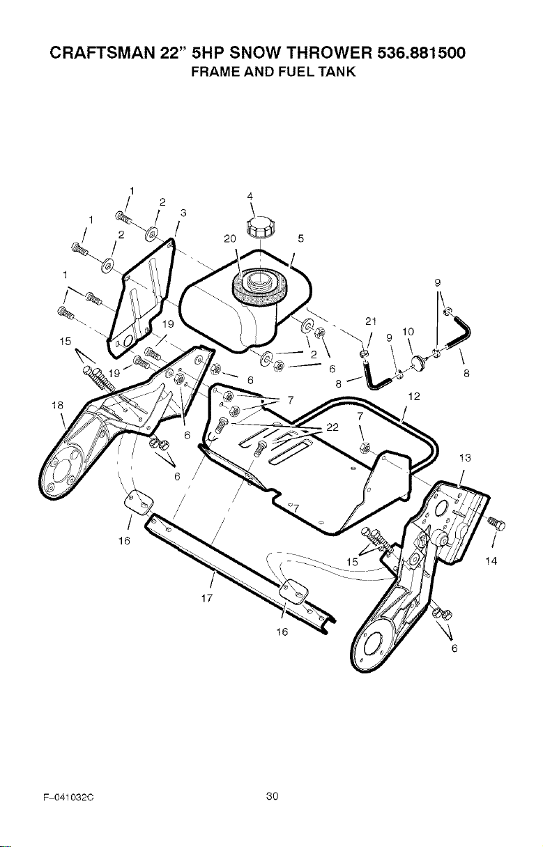
CRAFTSMAN 22" 5HP SNOW THROWER 536.881500
FRAME AND FUEL TANK
1
1
15
18
1
3
2 / 20
16
t
17
16
21
12
\
8
6
13
/
14
F 041032C 30
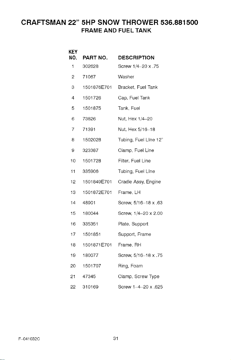
CRAFTSMAN 22" 5HP SNOW THROWER 536.881500
FRAME AND FUEL TANK
KEY
NO. PART NO, DESCRIPTION
1 302628 Screw 1/4 20 x .75
2 71067 Washer
3 1501876E701 Bracket, Fuel Tank
4 1501726 Cap, Fuel Tank
5 1501875 Tank, Fuel
6 73826 Nut, Hex 1/4 20
7 71391 Nut, Hex 5/16 18
8 1502028 Tubing, Fuel Line 12"
9 323387 Clamp, Fuel Line
10 1501728 Filter, Fuel Line
11 335906 Tubing, Fuel Line
12 1501849E701 Cradle Assy, Engine
13 1501872E701 Frame, LH
14 48901 Screw, 5/16 18 x .63
15 180044 Screw, 1/4 20 x 2.00
16 335351 Plate, Support
17 1501851 Support, Frame
18 1501871E701 Frame, RH
19 180077 Screw, 5/16 18 x .75
20 1501707 Ring, Foam
21 47345 Clamp, Screw Type
22 310169 Screw 1 4 20 x .625
F 041032C 31
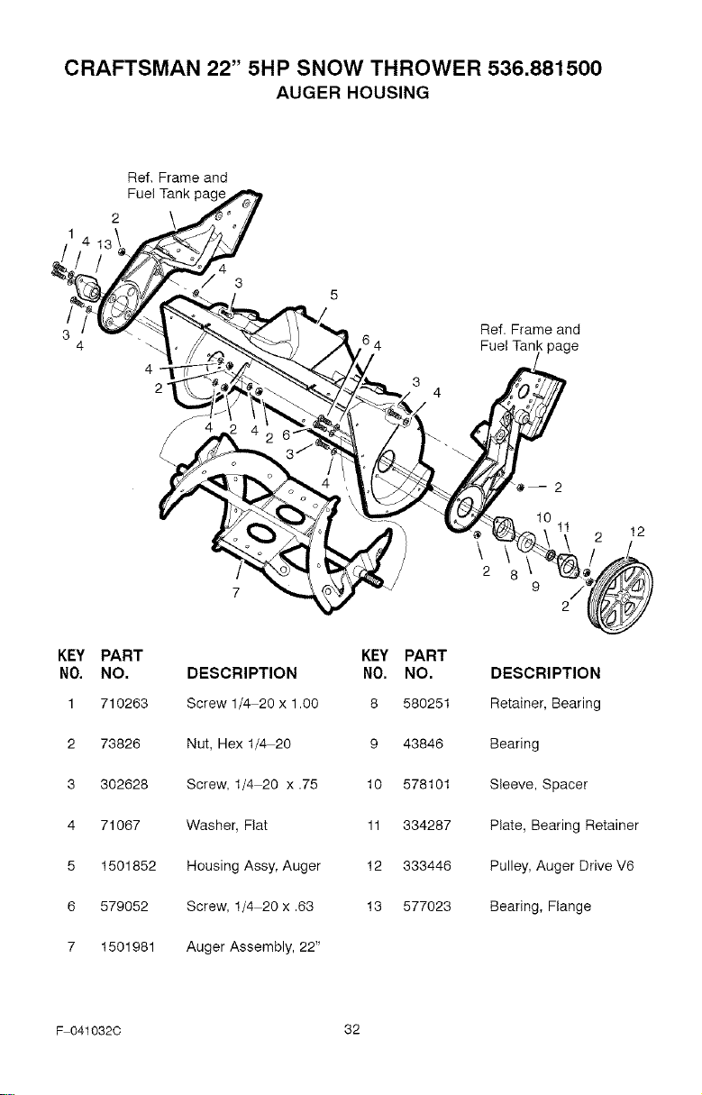
CRAFTSMAN 22" 5HP SNOW THROWER 536.881500
AUGER HOUSING
Ref, Frame and
Fuel Tank
4
2 3
4
Ref. Frame and
Fuel Tank page
KEY PART KEY PART
NO. NO. DESCRIPTION NO. NO.
1 710263 Screw 1/4 20 x 1.O0 8 580251
2 73826 Nut, Hex 1/4 20 9 43846
3 302628 Screw, 1/4 20 x .75 10 578101
4 71067 Washer, Flat 11 334287
5 1501852 Housing Assy, Auger 12 333446
6 579052 Screw, 1/4 20 x .63 13 577023
7 1501981 Auger Assembly, 22"
2
11 12
\
2 8
9 2/
DESCRIPTION
Retainer, Bearing
Bearing
Sleeve, Spacer
Plate, Bearing Retainer
Pulley, Auger Drive V6
Bearing, Flange
F 041032C 32
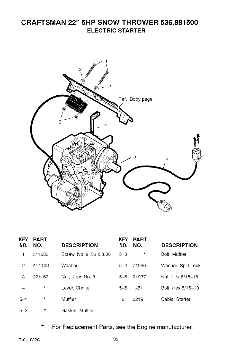
CRAFTSMAN 22" 5HP SNOW THROWER 536.881500
ELECTRIC STARTER
t
3
Ref. Body page
KEY PART KEY PART
NO. NO. DESCRIPTION NO. NO. DESCRIPTION
1 311633 Screw, No. 8 32 x 3.00 5 3 * Bolt, Muffler
2 414106 Washer 5 4 71060 Washer, Split Lock
3 271163 Nut, Keps No. 8 5 5 71037 Nut, Hex 5/16 18
4 * Lever, Choke 5 6 lx81 Bolt, Hex 5/16 18
5 1 * Muffler 6 6219 Cable, Starter
5 2 * Gasket, Muffler
F 041032C
For Replacement Parts, see the Engine manufacturer,
33
CRAFTSMAN 22" 5HP SNOW THROWER 536.881500
HANDLE ASSEMBLY
2
\ 1
8
\
13
14
Ref. Frame and
Fuel Tank page
12
12
11
10
lO
13
\
3-i
F 041032C 34
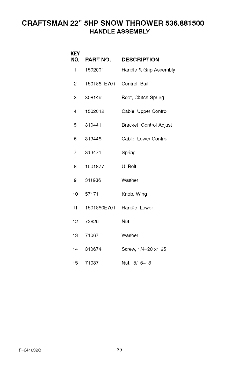
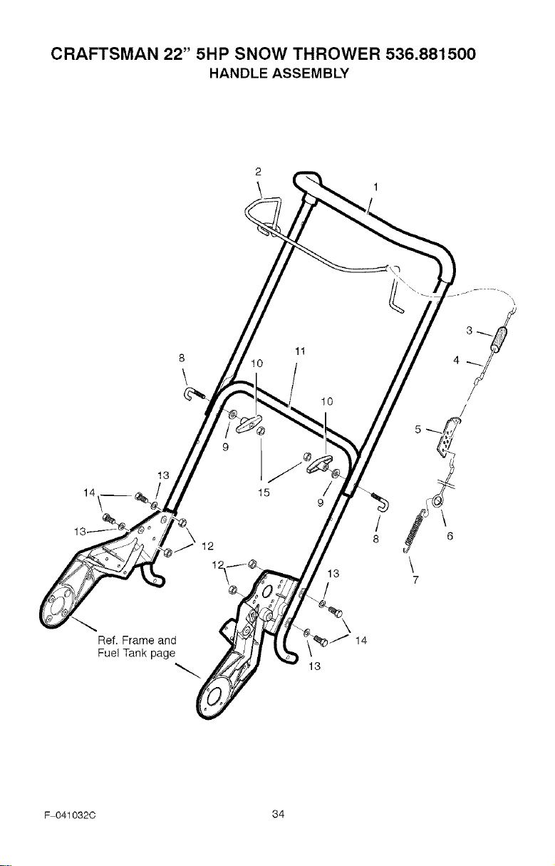
CRAFTSMAN 22" 5HP SNOW THROWER 536.881500
HANDLE ASSEMBLY
KEY
NO. PART NO, DESCRIPTION
1 1502001 Handle & Grip Assembly
2 1501861 E701 Control, Bail
3 308146 Boot, Clutch Spring
4 1502042 Cable, Upper Control
5 313441 Bracket, Control Adjust
6 313448 Cable, Lower Control
7 313471 Spring
8 1501877 U Bolt
9 311936 Washer
10 57171 Knob, Wing
11 1501860E701 Handle, Lower
12 73826 Nut
13 71067 Washer
14 313674 Screw, 1/4 20 x1.25
15 71037 Nut, 5/16 18
F 041032C 35
CRAFTSMAN 22" 5HP SNOW THROWER 536.881500
CHUTE ASSEMBLY
911
/
20
21
22 --q
17
_!_ 1928
\
\
16
25
27
\
13
26
\
29
30
23
Ref, Auger page
32
33
/
34 /
34
1
34
34
F 041032C 36
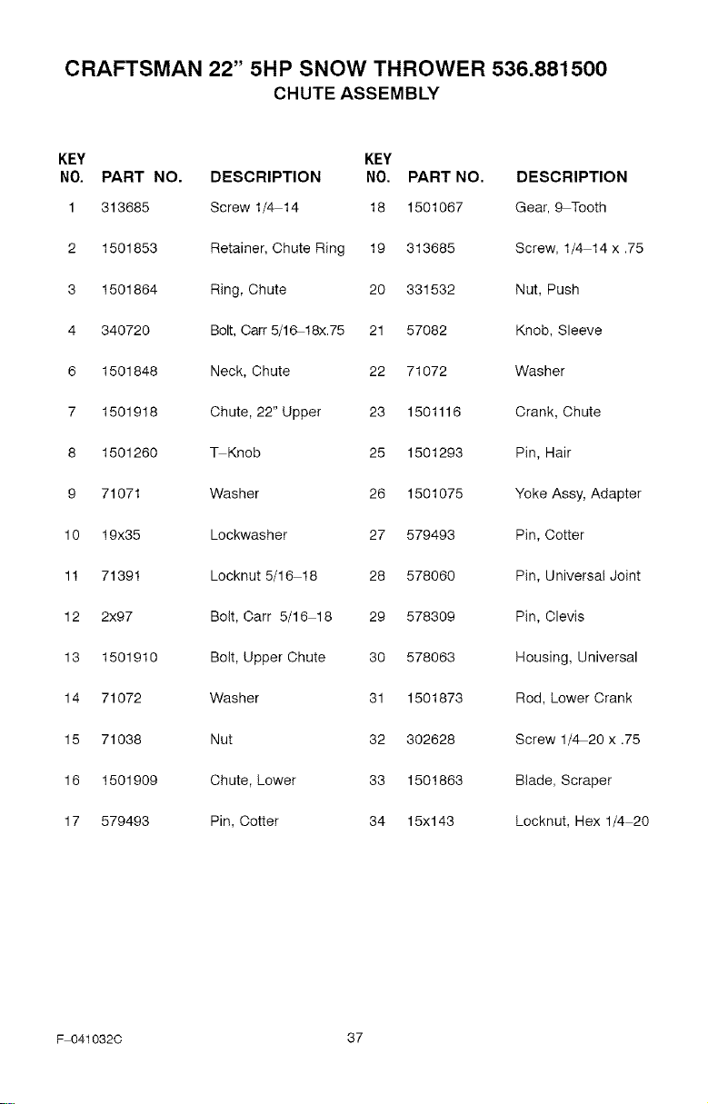
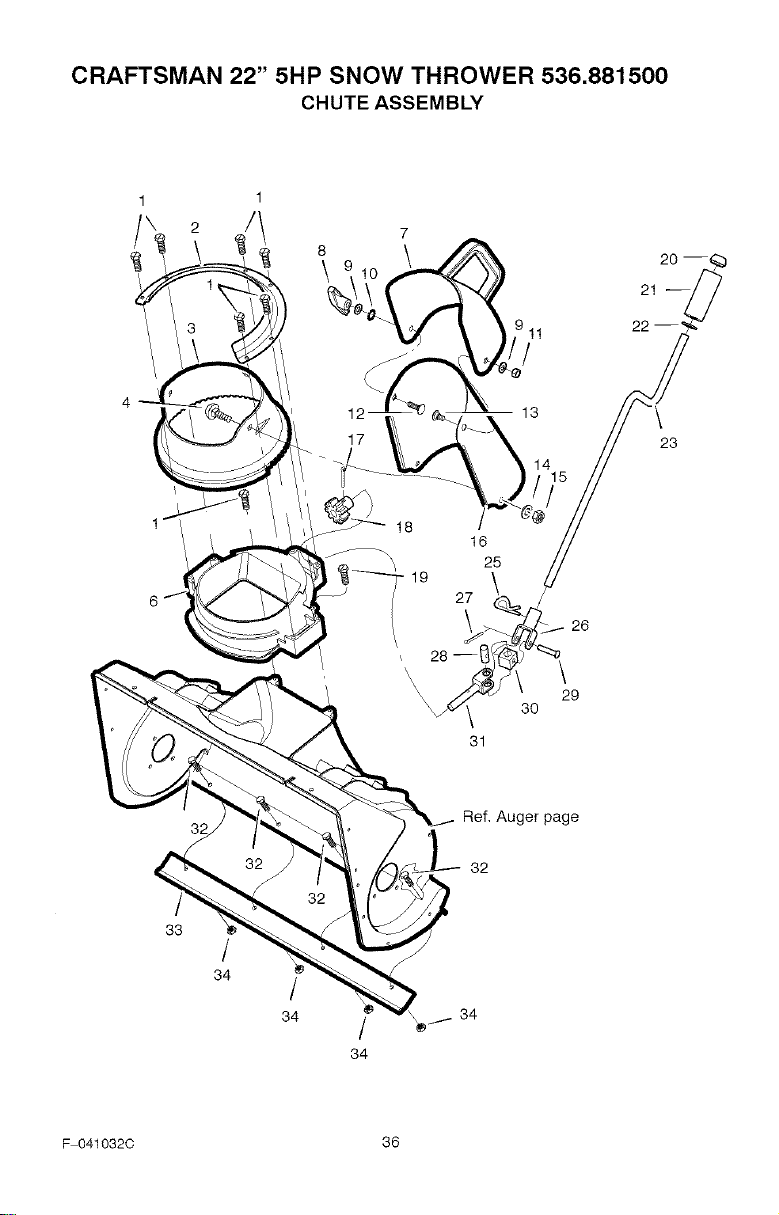
CRAFTSMAN 22" 5HP SNOW THROWER 536.881500
CHUTE ASSEMBLY
KEY KEY
NO. PART NO. DESCRIPTION NO. PART NO. DESCRIPTION
1 313685 Screw 1/4 14 18 1501067 Gear, 9 Tooth
2 1501853 Retainer, Chute Ring 19 313685 Screw, 1/4 14 x .75
3 1501864 Ring, Chute 20 331532 Nut, Push
4 340720 Bolt, Cart 5/1_18x.75 21 57082 Knob, Sleeve
6 1501848 Neck, Chute 22 71072 Washer
7 1501918 Chute, 22" Upper 23 1501116 Crank, Chute
8 1501260 _Knob 25 1501293 Pin, Hair
9 71071 Washer 26 1501075 Yoke Assy, Adapter
10 19x35 Lockwasher 27 579493 Pin, Cotter
11 71391 Locknut 5/16 18 28 578060 Pin, Universal Joint
12 2x97 Bolt, Carr 5/16 18 29 578309 Pin, Clevis
13 1501910 Bolt, Upper Chute 30 578063 Housing, Universal
14 71072 Washer 31 1501873 Rod, Lower Crank
15 71038 Nut 32 302628 Screw 1/4 20 x .75
16 1501909 Chute, Lower 33 1501863 Blade, Scraper
17 579493 Pin, Cotter 34 15x143 Locknut, Hex 1/4 20
F 041032C 37
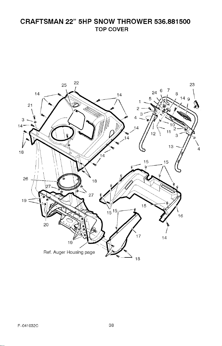
CRAFTSMAN 22" 5HP SNOW THROWER 536.881500
TOP COVER
21
\
23
24 6 7 8 1
18
\
4
26
19
20
19
Ref, Auger Housing page
\
17
18
/
14
16
F 041032C 38
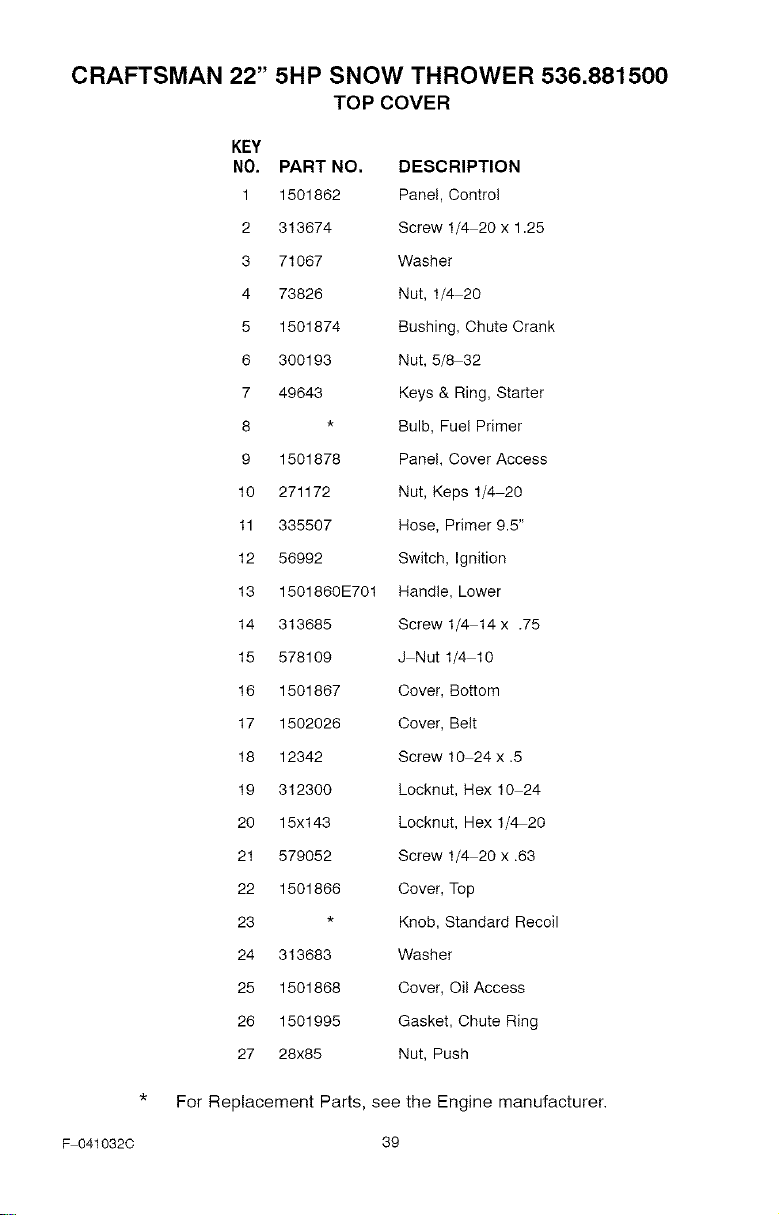
CRAFTSMAN 22" 5HP SNOW THROWER 536.881500
TOP COVER
KEY
NO. PART NO. DESCRIPTION
1 1501862 Panel, Control
2 313674 Screw 1/4 20 x 1.25
3 71067 Washer
4 73826 Nut, 1/4 20
5 1501874 Bushing, Chute Crank
6 300193 Nut, 5/8-32
7 49643 Keys & Ring, Starter
8 * Bulb, Fuel Primer
9 1501878 Panel, Cover Access
10 271172 Nut, Keps 1/4 20
11 335507 Hose, Primer 9.5"
12 56992 Switch, Ignition
13 1501860E701 Handle, Lower
14 313685 Screw 1/4 14 x .75
15 578109 J Nut 1/4 10
16 1501867 Cover, Bottom
17 1502026 Cover, Belt
18 12342 Screw 10 24 x .5
19 312300 Locknut, Hex 10 24
20 15x143 Locknut, Hex 1/4 20
21 579052 Screw 1/4 20 x .63
22 1501866 Cover, Top
23 * Knob, Standard Recoil
24 313683 Washer
25 1501868 Cover, Oil Access
26 1501995 Gasket, Chute Ring
27 28x85 Nut, Push
* For Replacement Parts, see the Engine manufacturer.
F 0410320 39
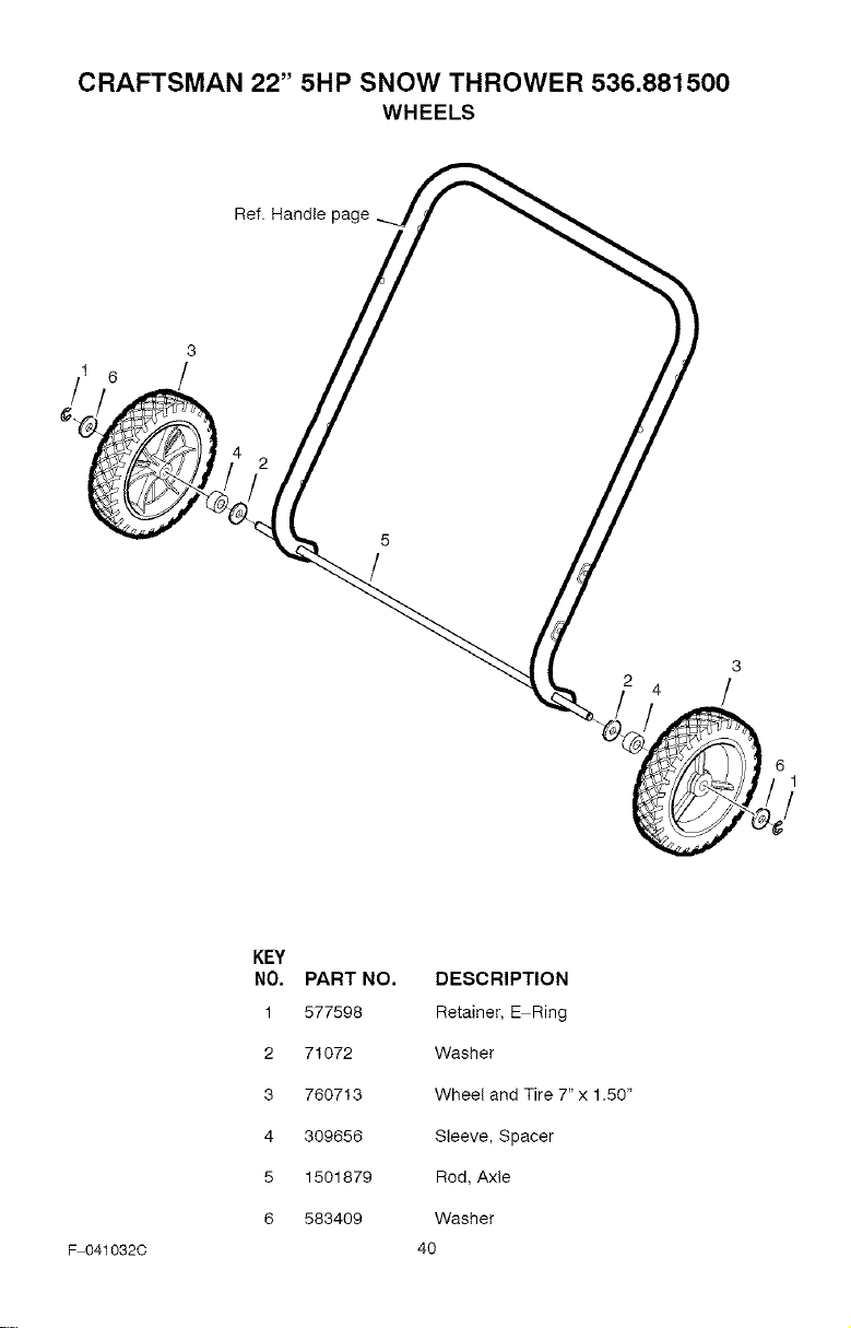
CRAFTSMAN 22" 5HP SNOW THROWER 536.881500
WHEELS
F 041032C
KEY
NO. PART NO. DESCRIPTION
1 577598 Retainer, E Ring
2 71072 Washer
3 760713 Wheel and Tire 7" x 1.50"
4 309656 Sleeve, Spacer
5 1501879 Rod, Axle
6 583409 Washer
4O
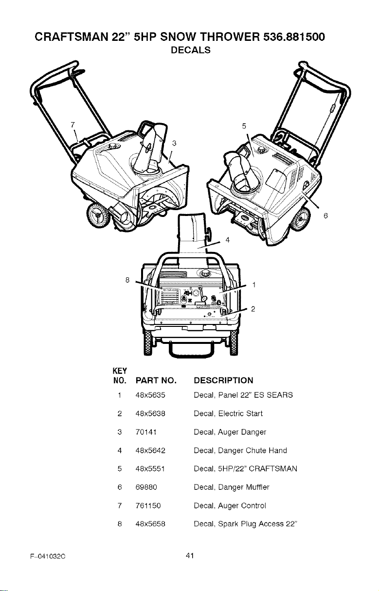
CRAFTSMAN 22" 5HP SNOW THROWER 536.881500
DECALS
1
2
KEY
NO.
1
2
3
4
5
6
7
8
PART NO.
48x5635
48x5638
70141
48x5642
48x5551
69880
761150
48x5658
DESCRIPTION
Decal, Panel 22" ES SEARS
Decal, Electric Start
Decal, Auger Danger
Decal, Danger Chute Hand
Decal, 5HP/22" CRAFTSMAN
Decal, Danger Muffler
Decal, Auger Control
Decal, Spark Plug Access 22"
F 041032C 41
BRIGGS&STRATTONENGINEMODEL9A413-O202-E1
3_ ENGNE _KET _E'I'
_4 _9¸
45 (
..... 15 _
10_ OPERAI_O_'_ _NUAt ]
F 0410320
Assemblies include all parts shown in frames.
42
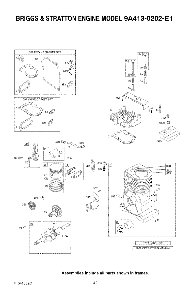
BRIGGS&STRATTONENGINEMODEL9A413-O202-E1
KEY PART KEY PART
NO. NO. DESCRIPTION NO. NO, DESCRIPTION
1 699088 Cylinder Assembly 30 691719 Dipper-Connecting
2 399269 Kit-Bushing/Seal Rod
(Magneto Side) 32 691664 Screw
3 _299819 Seal-Oil (Connecting Rod)
(Magneto Side) 33 497871 Valve-Exhaust
5 690386 Head-Cylinder 34 296677 Valve-intake
7_Q698717 Head-Cylinder Gasket 35 690520 Spring-Valve
8 699448 Breather Assembly (Intake)
9 695890 Gasket-Breather 36 690520 Spring-Valve
10 691666 Screw (Exhaust)
(Breather Assembly) 40 692194 Retainer-Valve
11 691246 Tube-Breather 45 691762 Tappet-Valve
12 _692218 Gasket-Crankcase 46 691998 Camshaft
(.015" Standard) 51 _Q692283 Gasket-Intake
13 691640 Screw 51A _273113 Gasket-Intake
(Cylinder Head) 219 496786 Gear-Governor
14 690361 Stud 220 691724 Washer
(Cylinder Head) (Governor Gear)
(Number 8 Position) 306 690461 Shield-Cylinder
15 691686 Plug-Oil Drain 307 691660 Screw
16 699092 Crankshaft (Cylinder Shield)
24 222698 Key-Flywheel 306 690462 Cover-Cylinder Head
25 699656 Piston Assembly 337 802592 Plug-Spark
(Standard) 358 496865 Gasket Set-Engine
Note- 383 89838 Wrench-Spark Plug
498670 Piston 529 692187 Grommet
Assembly 552 690508 Bushing-Governor
(.020" Oversize) Crank
26 695169 Ring Set 635 66538 Boot-Spark Plug
(Standard) 718 690959 Pin-Locating
Note-- 718A 499047 Pin-Locating
695172 Ring Set 741 691805 Gear-Timing
(.020" Oversize) 772 691003 Screw
27 691588 Lock-Piston Pin (Linkage Cover)
28 298909 Pin-Piston 869 691701 Seat-Valve
(Standard) (Intake)
Note-- 870 691702 Seat-Valve
298906 Pin-Piston (Exhaust)
(.005" Oversize) 871 262001 Bushing-Valve Guide
29 699655 Rod-Connecting 883 _691880 Gasket-Exhaust
(Standard) 925 699097 Cover-Linkage
Note -- 1019 496905 Kit-Label
296079 Rod- 1058 275697 Operator's Manual
Connecting 1095 498525 Gasket Set-Valve
(.020" Undersize) 1220 691105 Nut
_041032C 43
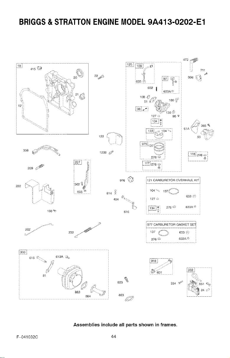
BRIGGS& STRATTONENGINEMODEL9A413-O202"E1
•
_7
63&&
_85
>76
ft76 _* CAI_L_ )[¢_q L>_ Oxfid:_FIA _J'L K_'f
_0_, 137
4_
3_5 <
_83 883
F 0410320
Assemblies include all parts shown in frames.
44
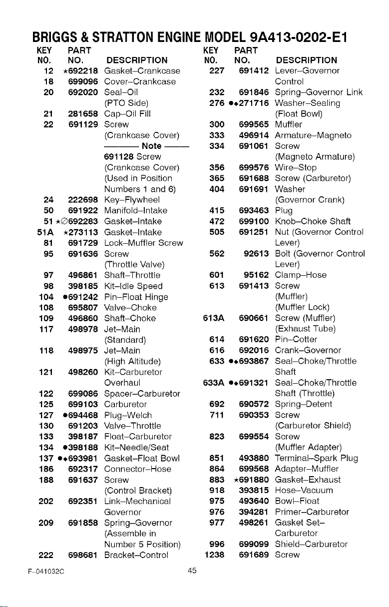
BRIGGS&STRATTONENGINEMODEL9A413-O202-E1
KEY PARTKEY PART
NO. NO.
12 _692218
18 699096
20 692020
21 281658
22 691129
24 222698
50 691922
51 _Q692283
51A _273113
81 691729
95 691636
97 496861
98 398185
104 o691242
108 695807
109 496860
117 498978
118 498975
121 498260
122 699086
125 699103
127 o694468
130 691203
133 398187
134 o398188
137 o.693981
186 692317
188 691637
202 692351
209 691858
222 698681
DESCRIPTION NO. NO. DESCRIPTION
Gasket-Crankcase 227 691412 Lever-Governor
Cover-Crankcase Control
Seal-Oil 232 691846 Spring-Governor Link
(PTO Side) 276 e_,271716 Washer-Sealing
Cap-Oil Fill (Float Bowl)
Screw 300 699565 Muffler
(Crankcase Cover) 333 496914 Armature-Magneto
Note-- 334 691061 Screw
691128 Screw (Magneto Armature)
(Crankcase Cover) 356 699576 Wire-Stop
(Used in Position 365 691688 Screw (Carburetor)
Numbers 1 and 6) 404 691691 Washer
Key-Flywheel (Governor Crank)
Manifold-Intake 415 693463 Plug
Gasket-intake 472 699100 Knob-Choke Shaft
Gasket-intake 505 691251 Nut (Governor Control
Lock-Muffler Screw Lever)
Screw 562 92613 Bolt (Governor Control
(Throttle Valve) Lever)
Shaff-Throttle 601 95162 Clamp-Hose
Kit-Idle Speed 613 691413 Screw
Pin-Float Hinge (Muffler)
Valve-Choke (Muffler Lock)
Shaft-Choke 613A 690661 Screw (Muffler)
Jet-Main (Exhaust Tube)
(Standard) 614 691620 Pin-Cotter
Jet-Main 616 692016 Crank-Governor
(High Altitude) 633 e_,693867 Seal-Choke/Throttle
Kit-Carburetor Shaft
Overhaul 633A e_,691321 Seal-Choke/Throttle
Spacer-Carburetor Shaft (Throttle)
Carburetor 692 690572 Spring-Detent
Plug-Welch 711 690353 Screw
Valve-Throttle (Carburetor Shield)
Float-Carburetor 823 699554 Screw
Kit-Needle/Seat (Muffler Adapter)
Gasket-Float Bowl 851 493880 Terminal-Spark Plug
Connector-Hose 864 699568 Adapter-Muffler
Screw 883 _691880 Gasket-Exhaust
(Control Bracket) 918 393815 Hose-Vacuum
Link-Mechanical 975 493640 Bowl-Float
Governor 976 394281 Primer-Carburetor
Spring-Governor 977 498261 Gasket Set-
(Assemble in Carburetor
Number 5 Position) 996 699099 Shield-Carburetor
Bracket-Control 1238 691689 Screw
_041032C 45
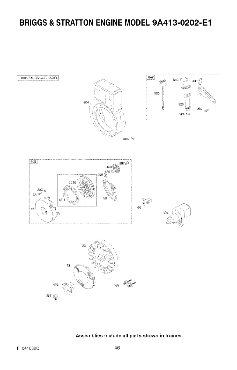
BRIGGS&STRATTONENGINEMODEL9A413-O202-E1
24 <
46_
73
F 041032C
Assemblies include all parts shown in frames.
46
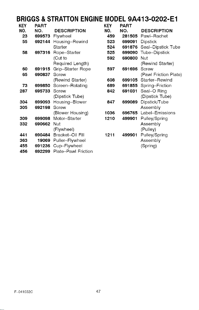
BRIGGS&STRATTONENGINEMODEL9A413-O202-E1
KEY PART KEY PART
NO. NO. DESCRIPTION NO. NO, DESCRIPTION
23 699573 Flywheel 459 281505 PawI-Rachet
55 692144 Housing-Rewind 523 699091 Dipstick
Starter 524 691876 Seal-Dipstick Tube
56 697316 Rope-Starter 525 699090 Tube-Dipstick
(Cut to 592 690600 Nut
Required Length) (Rewind Starter)
60 691915 Grip-Starter Rope 597 691696 Screw
65 690637 Screw (Pawl Friction Plate)
(Rewind Starter) 606 699105 Starter-Rewind
73 699650 Screen-Rotating 689 691655 Spring-Friction
287 695733 Screw 842 691031 Seal-O Ring
(Dipstick Tube) (Dipstick Tube)
304 699093 Housing-Blower 847 699089 Dipstick/Tube
305 692198 Screw Assembly
(Blower Housing) 1036 696765 Label-Emissions
309 699098 Motor-Starter 1210 499901 Pulley/Spring
332 690662 Nut Assembly
(Flywheel) (Pulley)
441 690484 Bracket-Oil Fill 1211 499901 Pulley/Spring
363 19069 Puller-Flywheel Assembly
455 691236 Cup-Flywheel (Spring)
456 692299 Plate-Pawl Friction
_041032C 47

F 041032C 48

F041032C 49
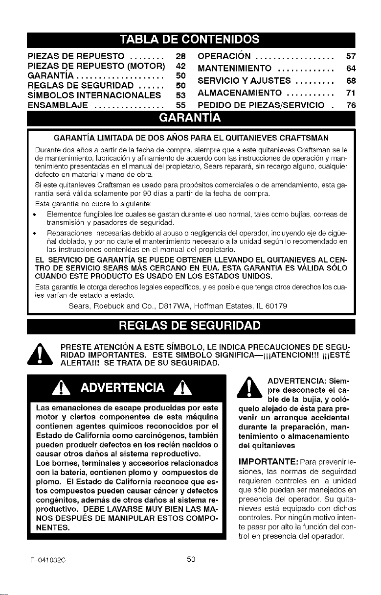
INIP'±q:] gF±qIm]::l[_o_o_
PIEZAS DE REPUESTO ........ 28
PIEZAS DE REPUESTO (MOTOR) 42
GARANTiA .................... 50
REGLAS DE SEGURIDAD ...... 50
SiMBOLOS INTERNACIONALES 53
ENSAMBLAJE ................ 55
OPERACION .................. 57
MANTENIMIENTO ............. 64
SERVICIO Y AJUSTES ......... 68
ALMACENAMIENTO ........... 71
PEDIDO DE PIEZAS/SERVICIO . 76
GARANTJA LIMITADA DE DOS AI_IOS PARA EL QUITANIEVES CRAFTSMAN
Durante dos aries a partir de la fecha de compra, siempre que a este quitanieves Craftsman se le
de mantenimiento, lubricaci6n y afinamiento de acuerdo con las instrucciones de operacion y man-
tenimJento presentadas en el manual del propietario, Sears reparar_k sin recargo alguno, cualquier
defecto en matedal y mano de obra.
Si este quitanieves Craftsman es usado para prop6sitos comercJales o de arrendamiento, esta ga-
rantia ser_t v_tlida solamente por 90 dias a partir de la fecha de compra.
Esta garantia no cubre Io siguiente:
• Elementos fungibles los cuales se gastan durante el uso normal, tales como bujias, correas de
transmisi6n y pasadores de seguddad.
• Reparaciones necesarias debido al abuso o negiigencia del operador, incluyendo eje de cigQe-
flal doblado, y por no darle el mantenimiento necesario a la unidad segQn Io recomendado en
las instrucciones contenidas en el manual del propietario.
EL SERVlClO DE GARANTJA SE PUEDE OBTENER LLEVANDO EL QUITANIEVES AL CEN-
TRO DE SERVlClO SEARS MAS CERCANO EN EUA. ESTA GARANTIA ES VALIDA SOLO
CUANDO ESTE PRODUCTO ES USADO EN LOS ESTADOS UNIDOS.
Esta garantia le otorga derechos legales especificos, yes posible que tenga otros derechos los cua-
les varian de estado a estado.
Sears, Roebuck and Co., D817WA, Hoffman Estates, IL 60179
PRESTE ATENCION A ESTE SJMBOLO, LE INDICA PRECAUCIONES DE SEGU-
RIDAD IMPORTANTES. ESTE SIMBOLO SIGNIFICA--iiiATENClON!!! iiiESTE
ALERTAt!! SE TRATA DE SU SEGURIDAD.
Las emanaciones de escape producidas pot este
motor y ciertos componentes de esta maquina
contisnen agentes quimicos reconocidos por el
Estado de California como carcinogenos, tambien
pueden producir defectos en los recien nacidos o
causar otros daSos al sistema reproductivo.
Los bornes, terminales y accesorios relacionados
con la bateria, contienen plomo y compuestos de
plomo. El Estado de California reconoce que es-
tos compuestos pueden causar cancer y defectos
congenitos, ademas de otros daSos al sistema re-
productivo. DEBE LAVARSE MUY BIEN LAS MA-
NOS DESPUE_S DE MANIPULAR ESTOS COMPO-
NENTES.
,_ ADVERTENCIA: Siem-pre desconecte el ca-
ble de la bujia, y col6-
quelo alejado de esta para pre-
venir un arranque accidental
durante la preparaci6n, man-
tenimiento o almacenamiento
del quitanieves
IMPORTANTE: Para prevenir le-
siones, las normas de seguirdad
requieren controles en la unidad
que s61opuedan ser manejados en
presencia del operador. Su quita-
nieves est,. equipado con dichos
controles. Por ningt_n motivo inten-
te pasar por alto la funci6n del con-
trol en presencia del operador.
F 041032C 50
CAPACITACION
1. Lea con atenci6n las instrucciones en e!
manual de operaci6n y servicio. Familiari-
cese completamente con los controles y
el use apropiado del quitanieves. Apren-
da a detener el quitanieves y a desen-
ganchar rapidamente los controles.
2. Nunca permita a nifios operar el quita-
nieves. Nunca permita que adultos ope-
ren el quitanieves sin la instrucci6n
apropiada.
3. Mantenga el _rea libre de personas, es-
pecialmente nifios pequefios y mascotas.
4. Tenga mucho cuidado para evitar resba-
Iones o caidas, especialmente cuando
est6 retrocediendo.
PREPARACION
1. Inspeccione completamente el area don-
de se usar& el quitanieves y retire todas
las esteras, trineos, tableros, cables y
otros objetos extrafios.
2. Desenganche todos los embragues antes
de hacer arrancar el motor.
3. No opere el quitanieves sin vestir pren-
das de invierno adecuadas para trabajar
a la intemperie. Vista calzado que le de
buena tracci6n sobre superficies resbalo-
sas.
4. Maneje el combustible con cuidado; 6ste
es altamente inflamable.
(a) Use un contenedor aprobado para
combustible.
(b) Nunca quite la tapa del tanque de
combustible ni afiada combustible a
un motor en marcha o a un motor ca-
liente.
(c) Llene el tanque de combustible al ai-
re libre y con mucho cuidado. Nunca
Ilene el tanque en un recinto cerrado.
(d) Vuelva a colocar la tapa del tanque
de combustible de manera segura, y
limpie el combustible derramado.
(e)
Nunca almacene combustible o el
quitanieves con combustible en el
tanque dentro de un edificio donde
los vapores pudiesen alcanzar algu-
na llama abierta o chispas.
(f) Verifique que el quitanieves tenga su-
ficiente combustible antes de cada
use, y deje un espacio adicional en el
tanque puesto que el calor del motor
F 0410320 51
y/o del sol hace que el combustible
se expanda.
5. Para todos los quitanieves con motores
de arranque electrico, use cables de ex-
tensi6n con certificaci6n OSA/UL. Use
solamente tomacorrientes que hayan si-
do instalados de acuerdo con los regla-
mentos de inspecci6n locales.
6. Permita que el motor y el quitanieves se
ajusten a las temperaturas exteriores an-
tes de comenzar a despejar la nieve.
7. Siempre use gafas de seguridad o pro-
tectores para los ojos durante la opera-
ci6n o mientras efect_a algt_n ajuste o
reparaci6n a la unidad, para proteger sus
ojos de objetos extrafios que pudiesen
ser lanzados per el quitanieves.
OPERACION
1. No opere este quitanieves si est& toman-
do medicinas que puedan causar somno-
lencia o afectar su habilidad para operar
el quitanieves.
2. No use el quitanieves si por motives
emocionales o fisicos se le dificulta ma-
nejarlo de forma segura.
3. No cotoque las manes o los pies cerca o
debajo de piezas en movimiento. Man-
t6ngase en todo memento a buena dis-
tancia de la abertura del tube de
descarga.
4. Tenga mucho cuidado al operar el quita-
nieves en o a trav6s de entradas de au-
tos, senderos o caminos de grava.
Mant6ngase alerta de peligros ocultos o
trafico.
5.. Si golpea un objeto extrafio, pare el mo-
tor, desconecte el cable de la bujia, ins-
peccione meticulosamente el quitanieves
per si hubiera alg0n dafio, y rep_trelo an-
tes de arrancar el motor y operar el quita-
nieves nuevamente.
6. Si el quitanieves comienza a vibrar de
manera excesiva, pare el motor y revfse-
Io inmediatamente para encontrar la cau-
sa. Generalmente, la vibraci6n es una
advertencia de algt_n problema.
7. Pare el motor cuando deje la posici6n de
operaci6n, antes de desobstruir el aloja-
miento de la barrena/propulsor o el tube
de descarga, y cuando efectQe cualquier
reparaci6n, ajuste o inspecci6n.
8. Cuando limpie, repare o inspeccione el
quitanieves, asegt_rese de que la barre-
na/propulsor y todas las partes m6viles
se encuentren detenidas, y que todos los
controles esten desenganchados. Desco-
necteelcabledelabujiaymant6ngalo
alejadodelabujiaparaevitarunarran-
queaccidental.
9. Tometodaslasprecaucionesposiblesal
dejarelquitanievesdesatendido.Desen-
ganchelabarrena/propulsor,pareelmo-
toryretirelaIlave.
10.Nohagaarrancarelmotorenrecintos
cerrados,a0nconlaspuertasyventanas
abiertas.Losvaporesdeescapesonpeli-
grosos(contienenMONOXIDODEOAR-
BONO,unGASINODOROyLETAL).
11.Nouseelquitanievesparalimpiar_treas
deterrenoinclinadas(cuestas,pendien-
tes).Tengamuchocuidadocuandocam-
biededirecci6n.Nointentelimpiar
pendientesmuypronunciadas.
12.Nuncaopereelquitanievessinquelos
resguardos,placasuotrosdispositivos
deseguridadseencuentrenensulugar.
13.Nuncaopereelquitanievescercadees-
caparatesdevidrio,autom6viles,vidrie-
ras,bajadas,ysimilares,sinelajuste
apropiadodelAngulodedescargadela
nieve.MantengaalosniBosylasmasco-
tasalejadosdelareaqueesterdespejan-
do.
14.Nosobrecarguelacapacidaddelquita-
nievesalintentarlimpiarlanieveauna
velocidaddemasiadorApida.
15.Nuncaopereelquitanievesaaltasveloci-
dadesdetransportesobresuperficies
resbalosas.Mirehaciaatrasytengacui-
dadoalretroceder.
16.Nuncadescarguedirectamentehaciaes-
pectadoresnipermitaanadiefrenteal
quitanieves.
17.Desenganchelafuerzamotrizdelaba-
rrena/propulsorcuandoelquitanieves
seatrasportadoonoest6enuse.
18.Utilice0nicamenteaditamentosyacceso-
riosaprobadosporelfabricantedelquita-
nieves(talescomecadenasparalas
ruedas,juegosdearranqueelectrico,
etc.).
19.Nuncaopereelquitanievessintenerbue-
navisibilidadoiluminaci6n.Aseg0rese
siemprequetienebuenaestabilidad,y
sujeteconfirmezaelmango.Oamine;
nuncacorra.
20.Notratedealcanzarareasdificiles.Man-
tengalaestabilidadyelbalanceentodo
memento.
21.Notratedeusarelquitanievesparalim-
piartechos.
MANTENIMIENTO Y
ALMACENAMIENTO
1. Revise los pernos con frecuencia para
asegurar que esten bien apretados y que
el quitanieves est6 en condiciones segu-
ras de funcionamiento.
2. Guarde el quitanieves a una distancia de
fuentes de ignici6n o de aparatos dom6s-
ticos que tengan llamas de encendido,
tales como calentadores de agua y estu-
fas, secadoras de ropa, etc. Permita que
el motor se enfrie antes de guardar el
quitanieves en cualquier recinto.
3. Siva a almacenar el quitanieves por un
perfodo prolongado, siempre consulte las
instrucciones del manual del operador
donde encontrara consejos importantes.
4. Mantenga o reemplace las etiquetas de
seguridad e instrucciones, segOn sea ne-
cesario.
5. Mantenga e! quitanieves en marcha unos
cuantos minutes despu6s de despejar la
nieve, para evitar que se congele la ba-
rrena/propulsor.
_lb ADVERTENCIA: Este quitanieves
es para uso en aceras, entradas
de auto y otras superficies de te-
rreno planas. Se debe tenet cuidado al
usar el quitanieves en superficies inclina-
das. NO USE EL QUITANIEVES EN SU-
PERFICIES SOBRE EL NIVEL DEL SUELO
tales como techos de residencias, de ga-
rajes, porches u otras estructuras o cons-
trucciones similares.
F 041032C 52
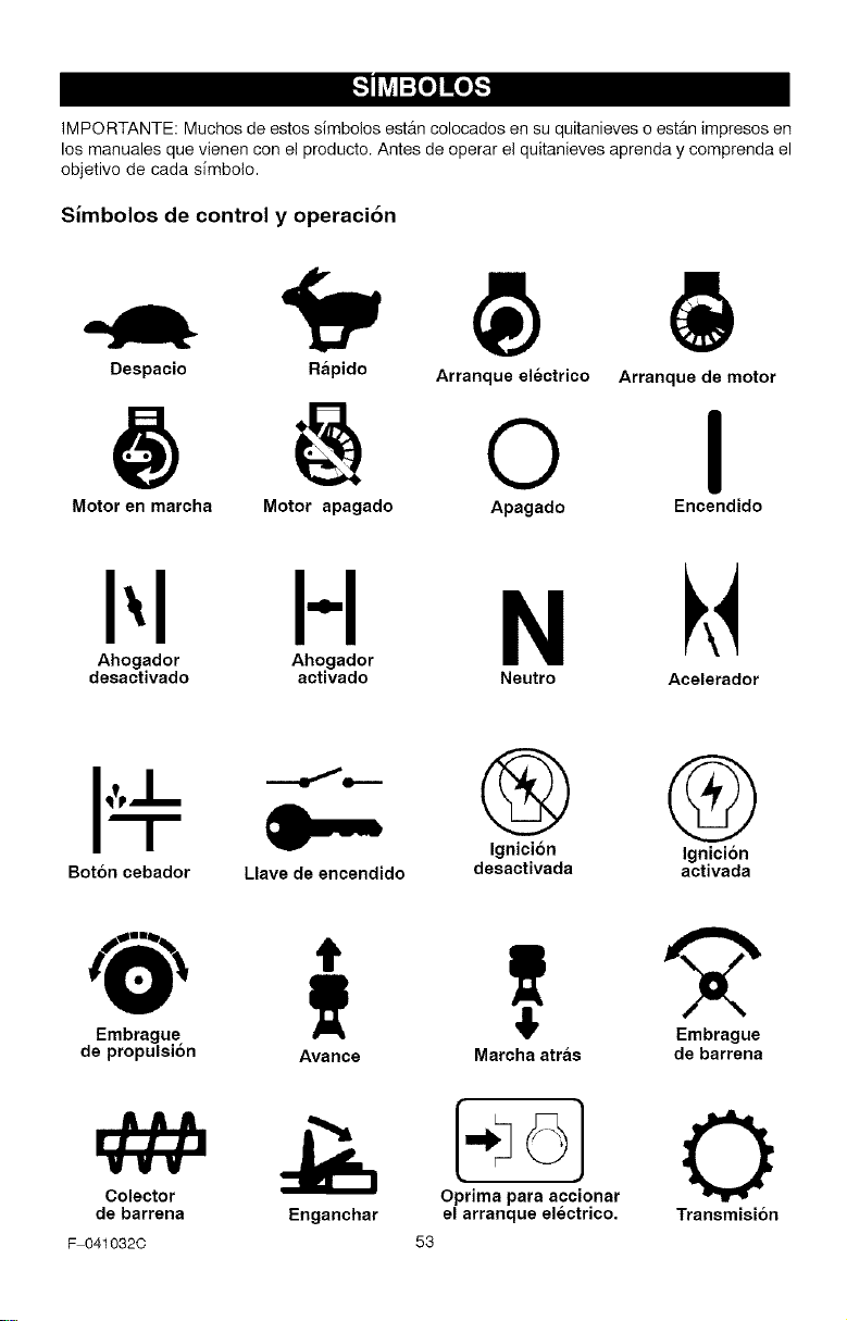
IMPORTANTE: Muchos de estos simbolos estAn colocados en su quitanieves o estAn impresos en
los manuales que vienen con el producto. Antes de operar el quitanieves aprenda y comprenda el
objetivo de cada s[mbolo.
Simbolos de control y operacibn
Despacio Rapido
Arranque electrico
@ @ o
Arranque de motor
I
Motor en marcha Motor apagado Apagado Encendido
I',I H N
Ahogador Ahogador
desactivado activado Neutro Acelerador
I"" =- ® @
Ignici6n Ignicion
Boton cebador Llave de encendido desactivada activada
Embrague
de propulsion Avarice
Colector
de barrena Enganchar
F 0410320
T "2"
Embrague
Marcha atras de barrena
53
o) 0
Oprima para accionar
el arranque electrico. Transmision
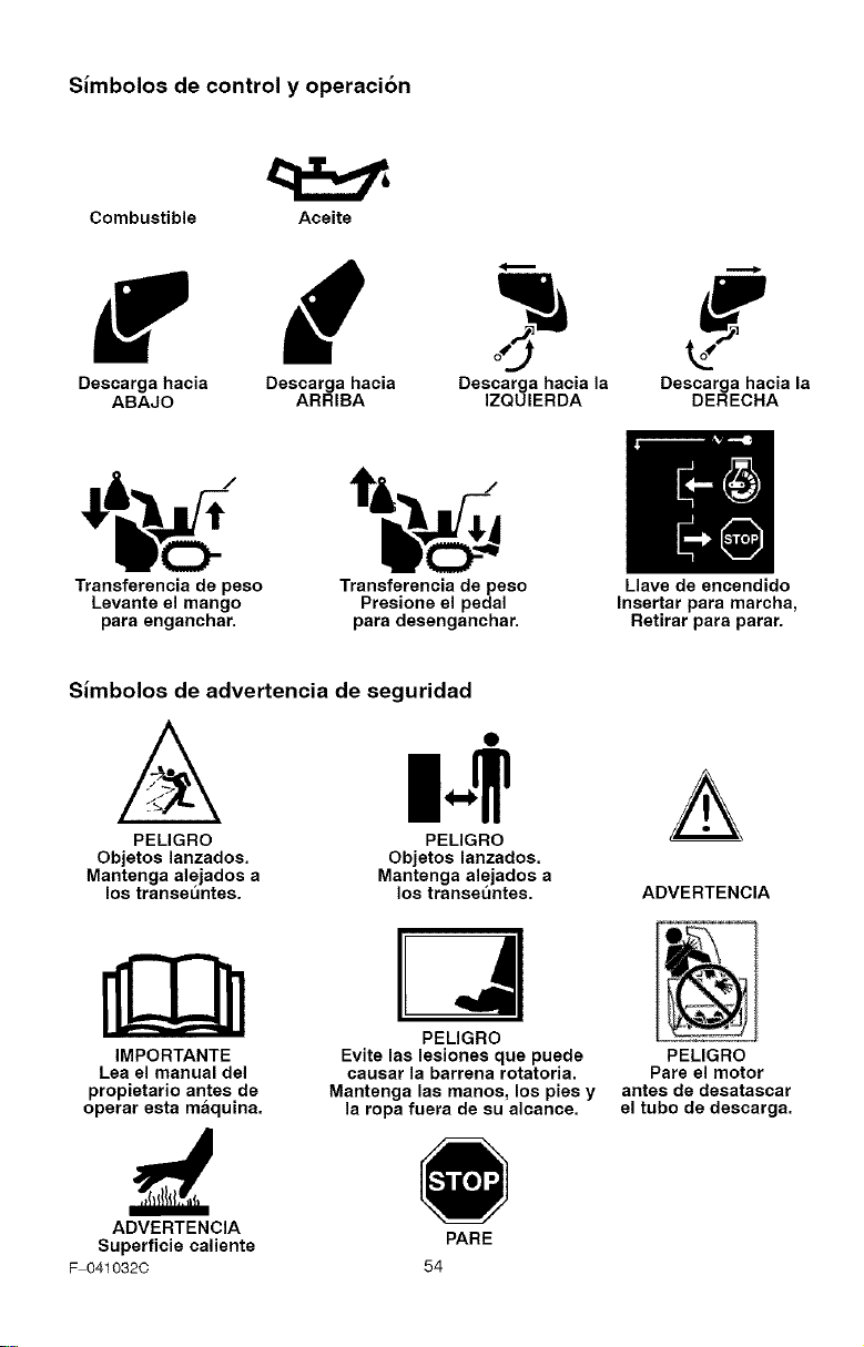
Simbolos de control y operacion
Combustible Aceite
Descarga hacia Descarga haeia Descarga hacia la Descarga hacia la
ABAJO ARRIBA IZQUIERDA DERECHA
I
|.m
Transferencia de peso Transferencia de peso Llave de encendido
Levante el mango Presione el pedal Insertar para marcha,
para enganehar, para desenganehar. Retirar para parar.
Simbolos de advertencia de seguridad
A m-+
PELIGRO PELIGRO
Objetos lanzados. Objetos lanzados.
Mantenga alejados a Mantenga alejados a
los transeuntes, los transet_ntes. ADVERTENCIA
IMPORTANTE
Lea el manual del
propietario antes de
opetar esta maquina.
PELIGRO
Evite las lesiones que puede
causar la barrena rotatoria.
Mantenga las manos, los pies y
la ropa fuera de su alcance.
PELIGRO
Pate el motor
antes de desataacat
el tubo de descarga.
ADVERTENCIA
Superficie caliente
F 041032C
54
PARE
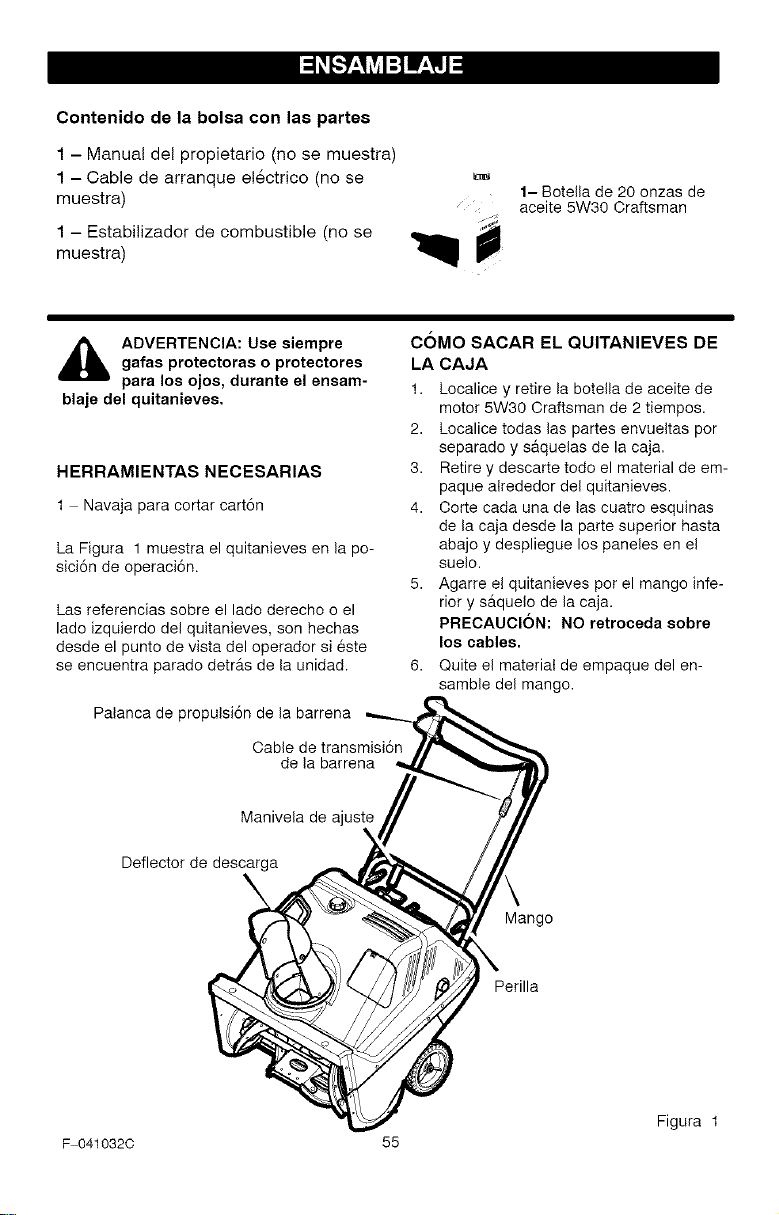
Contenido de la bolsa con las partes
1 - Manual del propietario (no se muestra)
1 - Cable de arranque el6ctrico (no se
muestra)
1 - Estabilizador de combustible (no se
muestra)
1- Botella de 20 onzas de
aceite 5W30 Craftsman
ADVERTENCIA: Use siempre
gafas protectoras o protectores
para los ojos, durante el ensam-
blaje del quitanieves.
HERRAMIENTAS NECESARIAS
1 Navaja para cortar cart6n
La Figura 1 muestra el quitanieves en la po-
sici6n de operaci6n.
Las referencias sobre el lado derecho o el
lado izquierdo del quitanieves, son hechas
desde el punto de vista del operador si este
se encuentra parado detr_ts de la unidad.
Palanca de propulsi6n de la barrena
Cable de transmisi6n
de la barrena
C6MO SACAR EL QUlTANIEVES DE
LA CAJA
1. Localice y retire la botella de aceite de
motor 5W30 Craftsman de 2 tiempos.
2. Localice todas las partes envueltas por
separado y s&quelas de la caja,
3. Retire y descarte todo el material de em-
paque alrededor del quitanieves.
4. Corte cada una de las cuatro esquinas
de la caja desde la parte superior hasta
abajo y despliegue los paneles en el
suelo.
5. Agarre el quitanieves por el mango infe-
rior y s_tquelo de la caja.
PRECAUCI6N: NO retrooeda sobre
los cables.
6. Quite el material de empaque del en-
samble del mango.
Manivela de ajuste
Deflector de descarga
Mango
Perilla
Figura 1
F 0410320 55
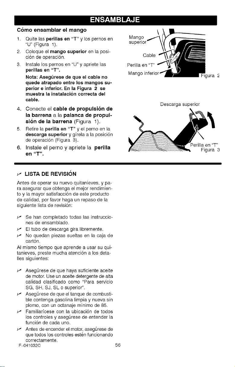
Como ensamblar el mango
1. Quite las perillas en "T" y los pernos en
"U" (Figura 1).
2. Ooloque el mango superior en la posi-
ci6n de operaci6n.
3. Instale los pernos en "U" y apriete las
perillas en "T'.
Nota: Asegt_rese de que el cable no
quede atrapado entre los mangos su-
perior e inferior. En la Figura 2 se
muestra la instalacion correcta del
cable.
4. Conecte el cable de propulsion de
la barrena a la palanca de propul-
sion de la barrena (Figura 1).
5. Retire laperilla en "T" y el perno en la
descarga superior y girela a la posici6n
de operaci6n (Figura 3).
6. Instale e! perno y apriete la perilla
en "T".
\
Mango
superior
Cable
Perilla en "T"
Mang
Descarga superior
igura .c
Perilla en "T"
Figura 3
_" LISTA DE REVISI6N
Antes de operar su nuevo quitanieves, y pa-
ra asegurar que obtenga el mejor rendimien-
to y la mayor satisfacci6n de este producto
de calidad, per favor haga un repaso de la
siguiente lista de revisi6n:
_" Se han completado todas las instruccio-
nes de ensamblado.
_" El tube de descarga gira libremente.
_" No quedan piezas sueltas en la caja de
cart6n.
AI mismo tiempo que aprende a usar su qui-
tanieves, preste mucha atenci6n a los deta-
lies siguientes:
_" Asegt_rese de que haya suficiente aceite
de motor. Use un aceite detergente de alta
calidad clasificado come "Para servicio
SG, SH, SJ, SL o superior".
_" Asegt_rese de que el tanque de combusti-
ble contenga gasolina limpia y nueva sin
plomo, con un octanaje minimo de 85.
_" Familiaricese con la ubicaci6n de todos
los controles y asegOrese de entender la
funci6n de cada uno.
_" Antes de encender el motor, asegt_rese de
que todos los controles esten funcionando
correctamente.
F 0410320
56
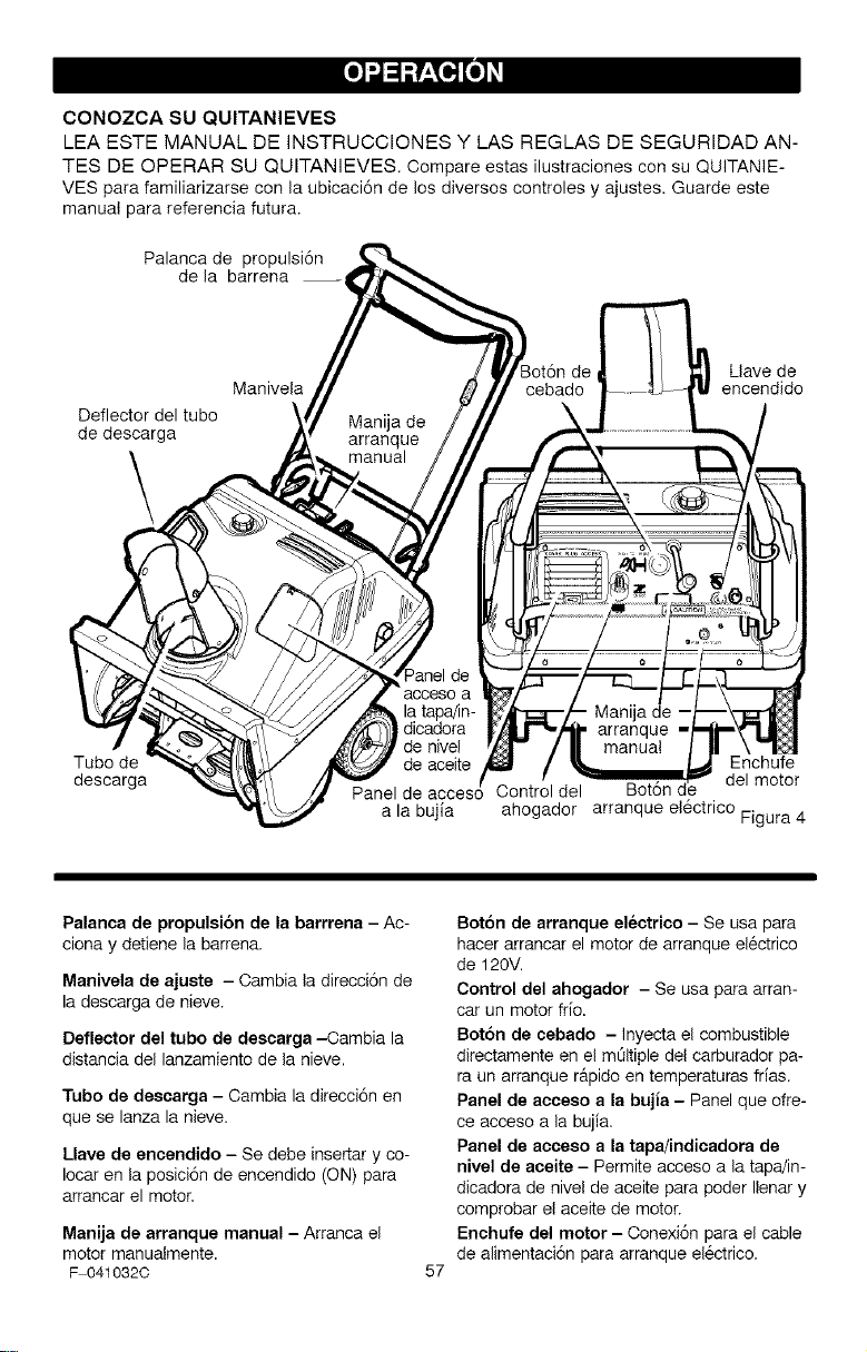
CONOZCASUQUITANIEVES
LEAESTEMANUALDEINSTRUCCIONESYLASREGLASDESEGURIDADAN-
TESDEOPERARSUQUITANIEVES.CompareestasilustracionesconsuQUITANIE-
VESparafamiliarizarseconlaubicaci6ndelosdiversoscontrolesyajustes.Guardeeste
manualparareferenciafutura.
Palancadepropulsi6n
delabarrena--
Deflectordeltubo
dedescarga
\
Llave de
Manivela encendido
Tubo de
descarga
Enchufe
Control del Bot6n d del motor
a la bujia ahogador arranque el6ctrico Figura 4
Palanca de propulsion de la barrrena - Ac-
ciona y detiene la barrena.
Manivela de ajuete - Cambia la direcci6n de
la descarga de nieve.
Deflector del tubo de descarga -Cambia la
distancia del lanzamiento de la nieve.
Tubo de deecarga - Cambia la direcci6n en
que se lanza la nieve.
Llave de encendido - Se debe insertar y co-
Iocar en la posici6n de encendido (ON) para
arrancar el motor.
Manija de arranque manual - Arranca el
motor manualmente.
F 041032C
57
Boton de arranque electrico - Se usa para
hacer arrancar el motor de arranque el6ctrico
de 120V.
Control del ahogador - Se usa para arran-
car un motor frio.
Boton de cebado - Inyecta el combustible
directamente en el mOltiple del carburador pa-
ra un arranque r&pido en temperaturas frias.
Panel de acceeo a la bujia - Panel que ofre-
ce acceso a la bujia.
Panel de acceeo a la tapa/indicadora de
nivel de aceite - Permite acceso a la tapa/in-
dicadora de nivel de aceite para poder Ilenar y
comprobar el aceite de motor.
Enchufe del motor - Conexi6n para el cable
de alimentaci6n para arranque el6ctrico.
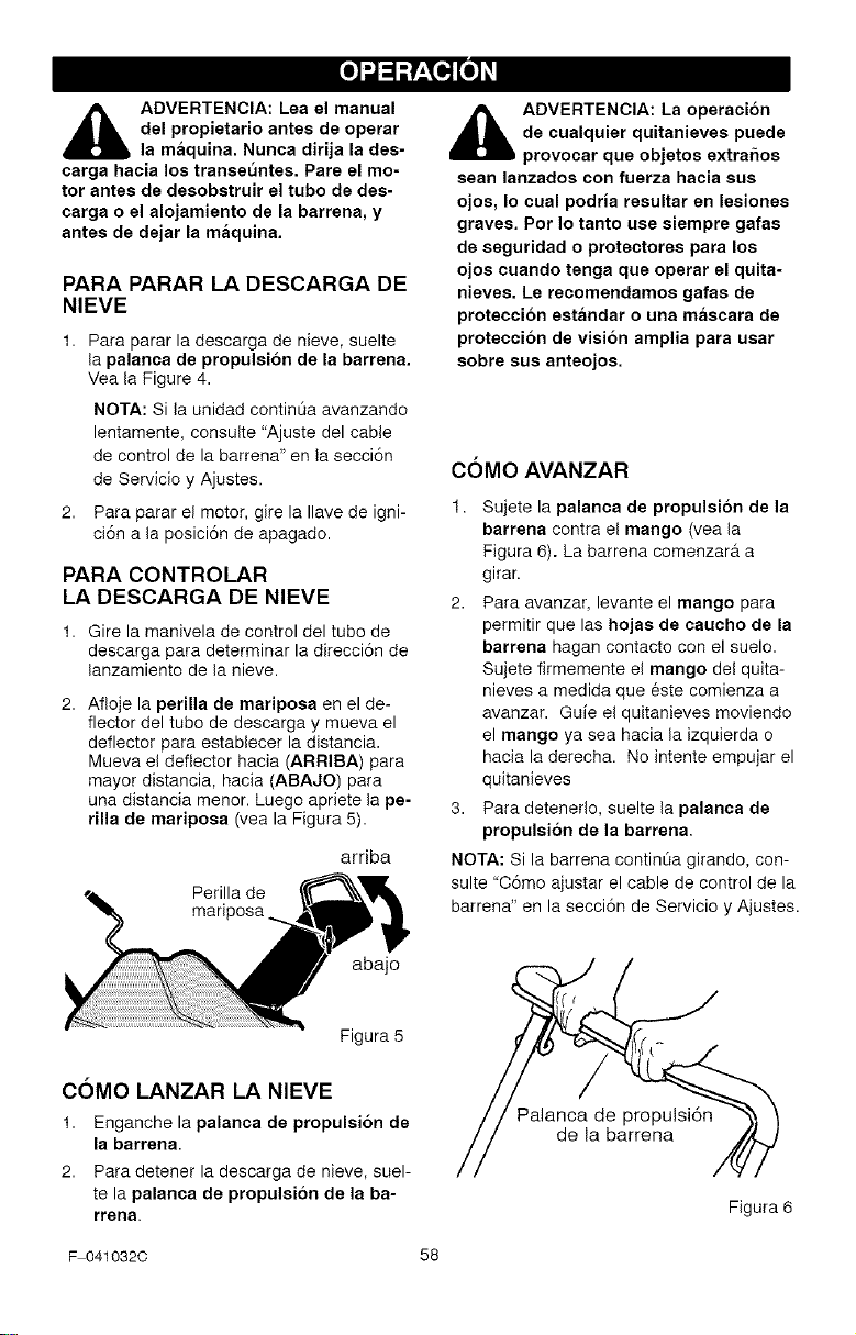
,_ ADVERTENCIA: Lea el manual
del propietario antes de operar
la maquina. Nunca dirija la des-
carga hacia los transeuntes. Pare el mo-
tor antes de desobstruir el tubo de des-
carga o el alojamiento de la barrena, y
antes de dejar la maquina.
PARA PARAR LA DESCARGA DE
NIEVE
1. Para parar la descarga de nieve, suelte
la palanca de propulsion de la barrena.
Vea la Figure 4.
NOTA: Si la unidad contint_a avanzando
lentamente, censure "Ajuste del cable
de control de la barrena" en la secci6n
de Servicio y Ajustes.
2. Para parar el motor, gire la Ilave de igni-
ci6n a la posici6n de apagado.
PARA CONTROLAR
LA DESCARGA DE NIEVE
1. Gire la manivela de control del tube de
descarga para determinar la direcci6n de
lanzamiento de la nieve.
2. Afloje la perilla de mariposa en el de-
flector del tube de descarga y mueva el
deflector para establecer la distancia.
Mueva el deflector hacia (ARRIBA) para
mayor distancia, hacia (ABAJO) para
una distancia menor. Luego apriete la pe-
rilla de mariposa (vea la Figura 5).
arriba
Perilla de
mariposa
abajo
Figura 5
C6MO LANZAR LA NIEVE
1. Enganche la palanca de propulsi6n de
la barrena.
2. Para detener la descarga de nieve, suel-
te la palanca de propulsi6n de la ba-
rrena.
i_ ADVERTENCIA: La operacion
de cualquier quitanieves puede
provoear que objetos extrahos
sean lanzados con fuerza haoia sus
ojos, Io cual podria resultar en lesiones
graves, Pot Io tanto use siempre gafas
de seguridad o proteotores para los
ojos cuando tenga que operar el quita-
nieves. Le reoomendamos gafas de
proteceion estandar o una mascara de
proteceion de vision amplia para usar
sobre sus anteojos.
C6MO AVANZAR
1. Sujete la palanca de propulsi6n de la
barrena contra el mango (vea la
Figura 6). La barrena comenzar& a
girar.
2. Para avanzar, levante el mango para
permitir que las hojas de caueho de la
barrena hagan contacto con el suelo.
Sujete firmemente el mango de! quita-
nieves a medida que este comienza a
avanzar. Guie el quitanieves moviendo
el mango ya sea hacia la izquierda o
hacia la derecha. No intente empujar el
quitanieves
3. Para detenedo, suelte la palanca de
propulsi6n de la barrena,
NOTA: Si la barrena contint_a girando, con-
suite "C6mo ajustar el cable de control de la
barrena" en la secci6n de Servicio y Ajustes.
de la barrena
Figura 6
F 041032C 58
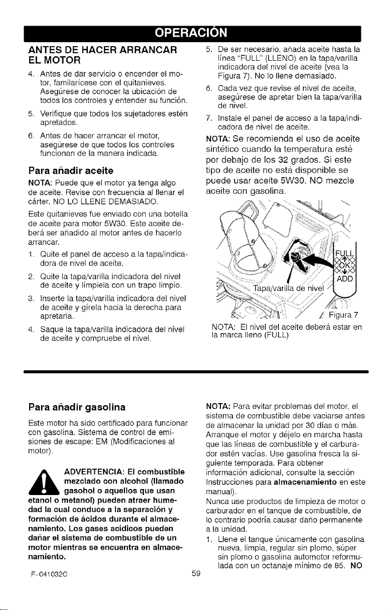
ANTES DE HACER ARRANCAR
EL MOTOR
4. Antes de dar servicio o encender el mo-
tor, familaricese con el quitanieves.
Aseg0rese de conocer la ubicaci6n de
todos los controles y entender su funci6n.
5. Verifique que todos los sujetadores esten
apretados.
6. Antes de hacer arrancar el motor,
aseg0rese de que todos los controles
funcionan de la manera indicada.
Para ar_adir aceite
NOTA: Puede que el motor ya tenga algo
de aceite, Revise con frecuencia al Ilenar el
c&rter. NO LO LLENE DEMASIADO.
Este quitanieves fue enviado con una botella
de aceite para motor 5W30. Este aceite de-
beret ser aSadido al motor antes de haceflo
arrancar.
1. Quite el panel de acceso a la tapa/indica-
dora de nivel de aceite.
2. Quite la tapa/varilla indicadora del nivel
de aceite y limpiela con un trapo limpio.
3. Inserte la tapa/varilla indicadora del nivel
de aceite y girela hacia la derecha para
apretarla.
4. Saque la tapa/varilla indicadora del nivel
de aceite y compruebe el nivel.
5. De set necesario, a_ada aceite hasta la
linea "FULL" (LLENO) en la tapa/varilla
indicadora del nivel de aceite (vea la
Figura 7). No Io Ilene demasiado.
6. Cada vez que revise el nivel de aceite,
asegQrese de apretar bien la tapa/varilla
de nivel.
7. Instale el panel de acceso a la tapa/indi-
cadora de nivel de aceite.
NOTA: Se recomienda el uso de aceite
sintetico cuando la temperatura est&
por debajo de los 32 grados. Si este
tipo de aceite no esta disponible se
puede usar aceite 5W30. NO mezcle
aceite con gasolina.
de
/ Figura 7
NOTA: El nivel del aceite debera estar en
la marca Ileno (FULL)
Para ar_adir gasolina
Este motor ha sido certificado para funcionar
con gasolina. Sistema de control de emi-
siones de escape: EM (Modificaciones al
motor).
,_ ADVERTENCIA: El combustible
mezclado con alcohol (llamado
gasohol o aquellos que usan
etanol o metanol) pueden atraer hume-
dad la cual conduce a la separacion y
formaci6n de acidos durante el almace-
namiento. Los gases acidicos pueden
dahar el sistema de combustible de un
motor mientras se encuentra en almace-
namiento.
F 041032C
59
NOTA: Para evitar problemas del motor, el
sistema de combustible debe vaciarse antes
de almacenar la unidad pot 30 dias o mrs.
Arranque el motor y d6jelo en marcha hasta
que las lineas de combustible y el carbura-
dot esten vacias. Use gasolina fresca la si-
guiente temporada. Para obtener
informaci6n adicional, consulte la secci6n
Instrucciones para almaeenamiento en este
manual).
Nunca use productos de limpieza de motor o
carburador en el tanque de combustible, de
Io contrario podria causar daho permanente
a la unidad.
1. Llene el tanque Qnicamente con gasolina
nueva, limpia, regular sin plomo, sQper
sin plomo o gasolina automotor reformu-
lada con un octanaje minimo de 85. NO
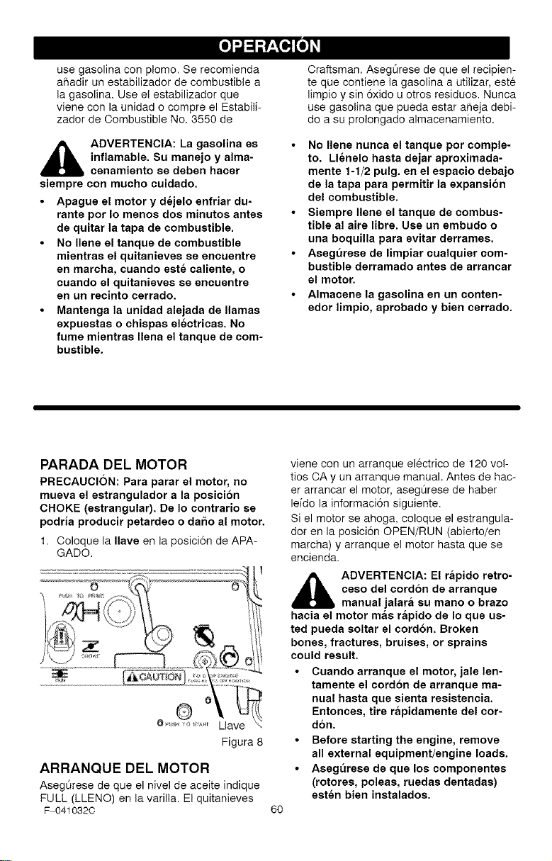
usegasolinaconplomo.Serecomienda
ahadirunestabilizadordecombustiblea
lagasolina.Useelestabilizadorque
vieneconlaunidadocompreelEstabili-
zadordeCombustibleNo.3550de
,_ ADVERTENCIA: La gasolina es
inflamable. Su manejo y alma-
cenamiento se deben hacer
siempre con mucho cuidado.
• Apague el motor y dejelo enfriar du-
rante pot Io menos dos minutos antes
de quitar la tapa de combustible.
• No Ilene el tanque de combustible
mientras el quitanieves se encuentre
en marcha, cuando este caliente, o
cuando el quitanieves se encuentre
en un recinto cerrado.
• Mantenga la unidad alejada de llamas
expuestas o chispas electricas. No
fume mientras Ilena el tanque de com-
bustible.
Craftsman. Aseg0rese de que el recipien-
te que contiene la gasolina a utilizar, este
limpio y sin 6xido u otros residuos. Nunca
use gasolina que pueda estar a_eja debi-
do a su prolongado almacenamiento.
• No Ilene nunca el tanque pot comple-
to. Llenelo hasta dejar aproximada-
mente 1-1/2 pulg. en el espacio debajo
de la tapa para permitir la expansi6n
del combustible.
• Siempre Ilene el tanque de combus-
tible al aire libre. Use un embudo o
una boquilla para evitar derrames.
• Aseg_rese de limpiar cualquier com-
bustible derramado antes de arrancar
el motor.
• Almacene la gasolina en un conten-
edor limpio, aprobado y bien cerrado.
PARADA DEL MOTOR
PRECAUCI6N: Para parar el motor, no
mueva el estrangulador a la posicion
CHOKE (estrangular). De Io contrario se
podria producir petardeo o da5o al motor.
1. Coloque la Ilave en ta posici6n de APA-
GADO.
Figura 8
ARRANQUE DEL MOTOR
Asegt_rese de que el nivel de aceite indique
FULL (LLENO) en la varilla. El quitanieves
F 0410320
6O
viene con un arranque el6ctrico de 120 vol-
tics CA y un arranque manual. Antes de hac-
er arrancar el motor, aseg0rese de haber
leido la informaci6n siguiente.
Si el motor se ahoga, coloque el estrangula-
dot en la posici6n OPEN/RUN (abierto/en
marcha) y arranque el motor hasta que se
encienda.
_ DVERTENCIA: El rapido retro-
ceso del cordon de arranque
manual jalara su mano o brazo
hacia el motor mas rapido de Io que us-
ted pueda soltar el cord6n. Broken
bones, fractures, bruises, or sprains
could result.
• Cuando arranque el motor, jale len-
tamente el cord6n de arranque ma-
nual hasta que sienta resistencia.
Entonces, tire rapidamente del cor-
d6n.
• Before starting the engine, remove
all external equipment/engine loads.
• Aseg_rese de que los componentes
(rotores, poleas, ruedas dentadas)
esten bien instalados.
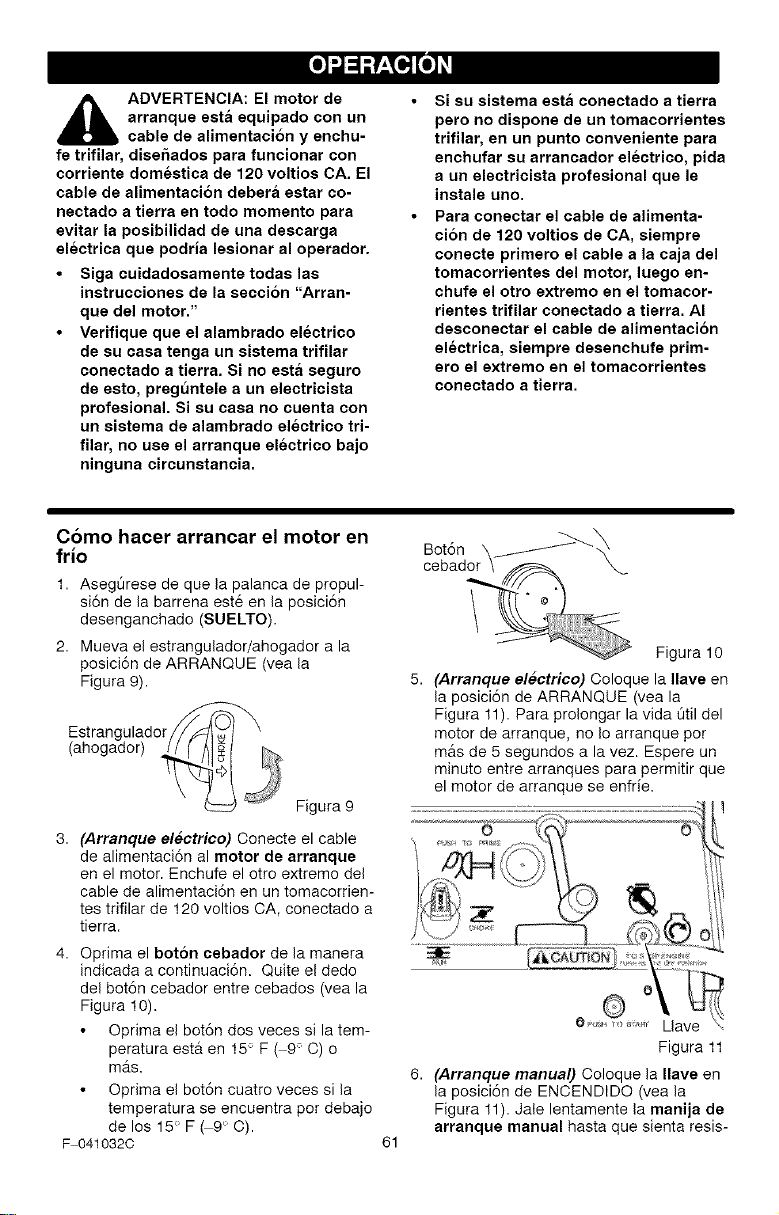
_lb DVERTENCIA: El motor de
arranque esta equipado con un
cable de alimentaci6n y enchu-
fe trifilar, diseftados para funcionar con
corriente domestica de 120 voltios CA. El
cable de alimentaci6n debera estar co-
neetado a tierra en todo momento para
evitar la posibilidad de una descarga
electrica que podria lesionar al operador.
• Siga cuidadosamente todas las
instrucciones de la secci6n "Arran-
que del motor."
• Verifique que el alambrado electrico
de su casa tenga un sistema trifilar
conectado a tierra. Si no esta seguro
de esto, pregt_ntele a un electricista
profesional. Si su casa no cuenta con
un sistema de alambrado electrico tri-
filar, no use el arranque electrico bajo
ninguna circunstancia.
Si su sistema esta conectado a tierra
pero no dispone de un tomacorrientes
trifilar, en un punto conveniente para
enchufar su arrancador electrico, pida
a un electricista profesional que le
instale uno.
Para conectar el cable de alimenta-
cion de 120 voltios de CA, siempre
conecte primero el cable a la caja del
tomacorrientes del motor, luego en-
chufe el otro extremo en el tomacor-
rientes trifilar conectado a tierra. AI
desconectar el cable de alimentacion
electrica, siempre desenchufe prim-
ero el extremo en el tomacorrientes
conectado a tierra.
Como hacer arrancar el motor en
frio
1. AsegOrese de que la palanca de propul-
si6n de la barrena est6 en la posici6n
desenganchado (SUELTO).
2. Mueva el estrangulador/ahogador a la
posici6n de ARRANQUE (vea la
Figura 9).
Estrangulador _'_
(ahogador) Figura 9
3. (Arranque electrico) Oonecte el cable
de alimentaci6n al motor de arranque
en el motor. Enchufe el otro extremo del
cable de alimentaci6n en un tomacorrien-
tes trifilar de 120 voltios CA, conectado a
tierra.
4. Optima el bot6n cebador de la manera
indicada a continuaci6n. Quite el dedo
del bot6n cebador entre cebados (vea la
Figura 10).
Oprima e! bot6n dos veces si la tem-
peratura esta en 15° F ( 9° O) o
m_s.
Oprima el bot6n cuatro veces si la
temperatura se encuentra pot debajo
de los 15° F _9 ° C).
F 0410320
Figura 10
5. (Arranque electrico) Coloque la Ilave en
la posici6n de ARRANQUE (vea la
Figura 11). Para prolongar la vida Otil del
motor de arranque, no Io arranque pot
m&s de 5 segundos a la vez. Espere un
minuto entre arranques para permitir que
el motor de arranque se enfrfe.
Figura 11
6. (Arranque manual) Coloque la Ilave en
la posici6n de ENCENDIDO (vea la
Figura 11). Jale lentamente la manija de
arranque manual hasta que sienta resis-
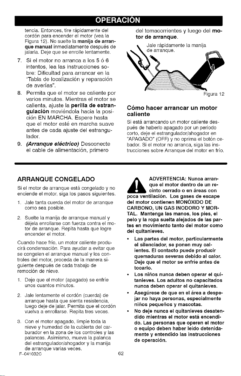
tencia.Entonces,tirer_tpidamentedel
cord6nparaencenderelmotor(veala
Figura12).Nosueltelamanijadearran-
qusmanualinmediatamentedespu6sde
jalarla.Dejequeseenrollelentamente.
7. Sielmotornoarrancaalos566
intentos,lealasinstruccionesso-
bre:Dificultadparaarrancarenla
"TabladeIocalizaci6nyreparaci6n
deaverias".
8. Permitaqueelmotorsecalientepor
variosminutos.Mientraselmotorse
calienta,ajustelaperilla de estran-
gulacion moviendola hacia la posi-
ci6n EN MARCHA. Espere hasta
que el motor este en marcha suave
antes de cada ajuste del estrangu-
lador.
9. (Arranque electrico) Desconecte
el cable de alimentaci6n, primero
del tomacorrientes y luego del mo-
tor de arranque.
Jale r&pidamente la manija
de arranque.
Figura 12
Como hacer arrancar un motor
caliente
Si est_ arrancando un motor calientedes-
puesde haberloapagado por un periodo
corto, deje elestrangulador/ahogador en
"APAGADO" (OFF) y no oprimae! bot6n ce-
bador,Si el motor no arranca, siga las ins-
trucciones sobre Arranque del motor en frio.
ARRANQUECONGELADO
Si el motor de arranque esta congelado y no
enciende el motor, siga los pasos siguientes.
1. Jale tanta cuerda del motor de arranque
como sea posible.
2. Suelte la manija de arranque manual y
d6jela enrollarse con fuerza contra el mo-
tor de arranque. Repita hasta que Iogre
encender el motor.
Ouando hace fifo, un motor caliente produ-
cirA condensaci6n. Para ayudar a evitar que
se congelen el arranque manual y los con-
troles del motor, proceda de la manera si-
guiente despues de cada trabajo de
remoci6n de nieve.
1. Deje que el motor (apagado) se enfrie
unos cuantos minutos.
2. Jale lentamente el cord6n (cuerda) de
arranque hasta que sienta resistencia,
luego deje de jalar. Permita que el cord6n
vuelva a enrollarse. Repita tres veces.
3. Con el motor apagado, limpie toda la
nieve y humedad de la cubierta del car-
burador en la zona de los controles y las
palancas. Asimismo, mueva la palanca
del estrangulador/ahogador y la manija
de arranque varias veces.
F 0410320
_ ADVERTENCIA: Nunca arran-
que el motor dentro de un re-
cinto cerrado o en areas con
poca ventilacion. Los gases de escape
del motor contienen MONOXIDO DE
CARBONO, UN GAS INODORO Y MOR-
TAB Mantenga las manos, los pies, el
pelo y la ropa suslta alejados de las par-
tes en movimiento tanto del motor como
del quitanieves.
• Las partes del motor, particularmente
el silenciador, se ponen muy cal-
ientes. El contacto puede producir
quemaduras severas debido al calor,
Deje que el motor se enfrJe antes de
tocarlo,
• Los ni_os nunca deben operar el qui-
tanieves. Los adultos no capacitados
nunca deben operar el quitanieves.
• Asegt_rese de queen el area a despe-
jar no haya personas, especialmente
ni5os pequehos y mascotas.
• No deje nunca el quitanieves desaten-
dido mientras el motor esta encendi-
do. Las personas que operen el motor
o equipo deben haber leido detenida-
mente y entendido las instrucciones
de operaci6n.
62
COMO RETIRAR OBJETOS
ATASCADOS EN LA BARRENA
,_ ADVERTENCIA: No intente re-
mover ningun objeto atascado
en la barrena sin tomar primero
las precauciones siguientes:
• Suelte la palanca de propulsi6n de la ba-
rrena.
• Gire la Ilave de ignici6n (encendido) a la
posici6n stop para parar el motor.
• Desconecte el cable de la bujia.
• No coloque las manos en la barrena o en
el tubo de descarga. Use una barra de
apalancamiento.
SUGERENCIAS PARA EL
LANZAMIENTO DE NIEVE
1. Cuando se levanta el mango, las hojas
de caucho de la barrena entran en con-
tacto con el suelo y el quitanieves avan-
za. Cuando se suelta la palanca de
propulsi6n de la barrena, las hojas de
caucho de la barrena se paran. Si las ho-
jas de caucho no paran, consulte "C6mo
ajustar el cable de propulsi6n de la barre-
na" en la secci6n de Servicio y Ajustes.
2. El lanzamiento de nieve mAs efectivo se
Iogra cuando la nieve se quita inmedia-
tamente despu6s de la nevada.
3. Para quitar completamente la nieve, so-
breponga ligeramente las pasadas del
quitanieves.
4. Ouando sea posible, descargue la nieve
a favor del viento.
5. Se puede ajustar la distancia a la que la
nieve serA lanzada, moviendo el deflec-
tor del tubo de descarga. Para mas dis-
tancia levante el deflector, para menos
distancia baje el deflector.
6. En condiciones de mucho viento, baje el
deflector del tubo de descarga para diri-
gir la nieve lanzada mas cerca del suelo
para evitar que el viento la sople hacia
Areas no deseadas.
7. Para su seguridad y para prevenir el da-
fio al quitanieves, mantenga el Area que
va a limpiar, libre de rocas, juguetes y
otros objetos extrafios.
8. Ouando est6 quitando la nieve sobre en-
tradas de auto cubiertas con grava o ro-
ca triturada, no deje que las cuchillas de
la barrena toquen el suelo. Mueva el
mango hacia abajo para levantar ligera-
mente las cuchillas de la barrena.
9. La velocidad de avance del quitanieves
depende de la profundidad y del peso de
la nieve. La manera mas eficiente de
F 0410320
63
usar el quitanieves serA determinada por
su experiencia bajo diversas condiciones.
10. Despu6s de cada trabajo deje que el
motor funcione por unos minutos. Asf
se derretirA la nieve y el hielo acumula-
dos en el motor.
11. Limpie el quitanieves despu6s de cada
USO.
12.Quite el hielo, la nieve y los residuos de
todo el quitanieves. Enjuaguelo con agua
para quitarle toda la sal y otros productos
quimicos. Seque el quitanieves.
NIEVE SECA Y DE
POCA PROFUNDIDAD
1. La nieve que se acumule hasta profundi-
dades de ocho pulgadas puede quitarse
rApida y fAcilmente, caminando a una
velocidad moderada con el quitanieves.
Para acumulaciones de nieve de mayor
profundidad, camine mAs lento para per-
mitir la descarga uniforme de nieve tan
pronto sea recogida pot la barrena.
2. Intente descargar la nieve a favor del
viento.
NIEVE MOJADA Y COMPACTA
Avance lentamente para despejar la nieve
mojada y compacta. Si este tipo de nieve
hace que la barrena gire mAs lento o empie-
za a atascar el tubo de descarga, retirese un
poco y empiece una serie de movimientos
cortos con el quitanieves, hacia adelante y
hacia atrAs. Estos movimientos cortos en la
nieve (de cuatro a seis pulgadas), ayudaran
a arrojar la nieve de! tubo de descarga.
BANCOS Y ACUMULACIONES
GRANDES DE NIEVE
Para despejar la nieve que se acumula a
una altura mayor que el quitanieves, use el
m6todo descrito anteriormente (movimientos
cortos hacia adelante y hacia atras). Oriente
el tubo de descarga en direcci6n opuesta a
la del banco o acumulaci6n grande de nieve.
La remoci6n de este tipo de nieve tomarA
mAs tiempo.
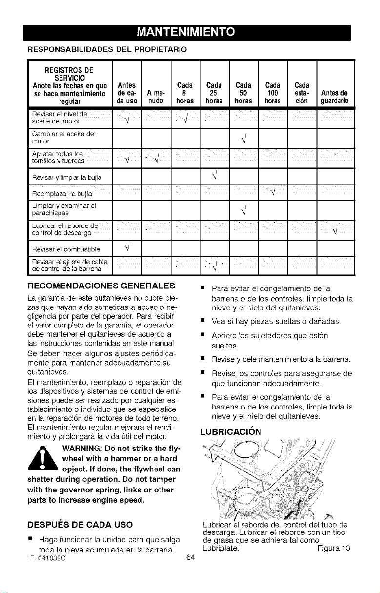
L_-' h, h, u h, o]
RESPONSABILIDADES DEL PROPIETARIO
REGISTROSDE
SERVICIO
Anotelas fechas en que Antes Cada Cada Cada Cada Cada
sehace mantenimiento de ca- A me- 8 25 50 t00 esta- Antesde
regular da uso nudo horas horas horas horas ci6n guardado
n n n n n n n n
Revisarel nivelde ' I I I I
aceite detmotor
Oambiarel aceite del
motor
i i
Apretar todos los
tomillos ytueroas
Revisarylimpiarla bujia
Limpiary examinarel
parachispas
hubricareI rebordede!
controt de desoarga _
Revisarel combustible
n n n n n n n
RevisareIajuste de cable " / I I I
de controlde la barrena " "_
RECOMENDACIONES GENERALES
La garantfa de este quitanieves no cubre pie-
zas que hayan sido sometidas a abuso o ne-
gligencia por parte del operador. Para recibir
el valor completo de la garantia, el operador
debe mantener el quitanieves de acuerdo a
las instrucciones contenidas en este manual.
Se deben hacer algunos ajustes peri6dica-
mente para mantener adecuadamente su
quitanieves.
El mantenimiento, reemplazo o reparaci6n de
los dispositivos y sistemas de control de emi-
siones puede set realizado por cualquier es-
tablecimiento o individuo que se especialice
en la reparaci6n de motores de todo terreno.
El mantenimiento regular mejorarA el rendi-
miento y prolongar_ la vida t_til del motor.
,_ WARNING: Do not strike the fly-
wheel with a hammer or a hard
opject. If done, the flywheel can
shatter during operation. Do not tamper
with the governor spring, links or other
parts to increase engine speed.
DESPUI_S DE CADA USO
• Haga funcionar la unidad para que salga
toda la nieve acumulada en la barrena.
F 0410320
• Para evitar el congelamiento de la
barrena o de los controles, limpie toda la
nieve y el hielo del quitanieves.
• Vea si hay piezas sueltas o dahadas.
• Apriete los sujetadores que est6n
sueltos.
• Revise y dele mantenimiento a la barrena.
• Revise los controles para asegurarse de
que funcionan adecuadamente.
• Para evitar el congelamiento de la
barrena o de los controles, limpie toda la
nieve y el hielo del quitanieves.
LUBRICACION
64
Lubricar el reborde del control del tubo de
descarga. Lubricar el reborde con un tipo
de grasa que se adhiera tal como
Lubriplate. Figura 13
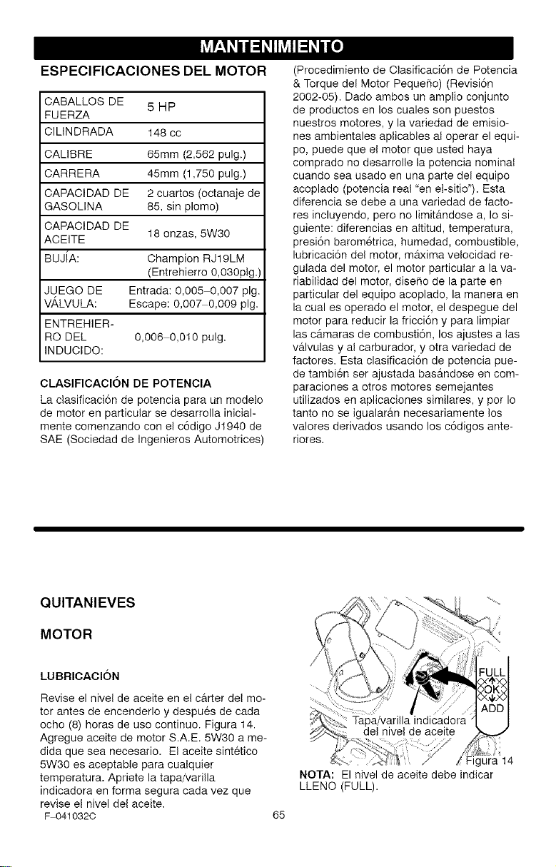
L_-' h, h, u h, o]
ESPEClFICAClONES DEL MOTOR
CABALLOS DE 5 HP
FUERZA
ClUNDRADA 148 cc
CALIBRE 65mm (2,562 pulg.)
CARRERA 45mm (1,750 pulg.)
CAPACIDAD DE 2 cuartos (octanaje de
GASOLINA 85, sin plomo)
CAPACIDAD DE
ACEITE 18 onzas, 5W30
BUJiA: Champion RJ19LM
(Entrehierro O,O3Oplg.)
JUEGO DE Entrada: 0,005 0,007 pig.
VA,LVULA: Escape: 0,007 0,009 pig.
ENTREHIER-
RO DEL 0,006 0,010 pulg.
INDUCIDO:
CLASIFICACl6N DE POTENClA
La clasificaci6n de potencia para un modelo
de motor en particular se desarrolla inicial-
mente comenzando con el c6digo J1940 de
SAE (Sociedad de Ingenieros Automotrices)
(Procedimiento de Clasificaci6n de Potencia
& Torque del Motor Pequefio) (Revisi6n
2002-05). Dado ambos un amplio conjunto
de productos en los cuales son puestos
nuestros motores, y la variedad de emisio-
nes ambientales aplicables al operar el equi-
pc, puede que el motor que usted haya
comprado no desarrolle la potencia nominal
cuando sea usado en una parte del equipo
acoplado (potencia real "en e!-sitio"). Esta
diferencia se debe a una variedad de facto-
res incluyendo, pero no limit&ndose a, Io si-
guiente: diferencias en altitud, temperatura,
presi6n barom@rica, humedad, combustible,
lubricaci6n del motor, maxima velocidad re-
gulada del motor, el motor particular a la va-
riabilidad del motor, diseBo de la parte en
particular del equipo acoplado, la manera en
la cual es operado el motor, el despegue del
motor para reducir la fricci6n y para limpiar
las c&maras de combusti6n, los ajustes alas
v&lvulas y al carburador, y otra variedad de
factores. Esta clasificaci6n de potencia pue-
de tambien ser ajustada bas&ndose en com-
paraciones a otros motores semejantes
utilizados en aplicaciones similares, y por Io
tanto no se igualar&n necesariamente los
valores derivados usando los c6digos ante-
riores.
QUITANIEVES
MOTOR
LUBRICAClON
Revise el nivel de aceite en el c&rter del mo-
tor antes de encenderlo y despues de cada
ocho (8) horas de uso continuo. Figura 14.
Agregue aceite de motor S.A.E. 5W30 a me-
dida que sea necesario. El aceite sintetico
5W30 es aceptable para cualquier
temperatura. Apriete la tapa/varilla
indicadora en forma segura cada vez que
revise el nivel del aceite.
F 0410320
65
jura 14
NOTA: El nivel de aceite debe indicar
LLENO (FULL).
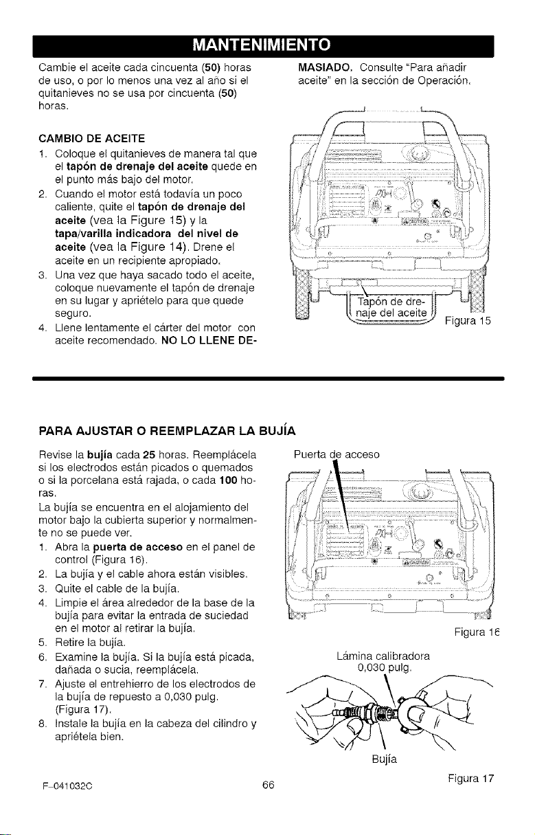
L_-' h, h, u h, o]
Oambie el aceite cada cincuenta (50) horas
de uso, o pot Io menos una vez al aSo si el
quitanieves no se usa por cincuenta (50)
horas.
MASIADO. Oonsulte "Para afiadir
aceite" en la secci6n de Operaci6n.
CAMBIO DE ACEITE
1. Coloque el quitanieves de manera tal que
el tap6n de drenaje del aeeite quede en
el punto mAs bajo del motor.
2. Cuando el motor esta todavia un poco
caliente, quite el tapon de drenaje del
aeeite (vea la Figure 15) y la
tapa/varilla indieadora del nivel de
aeeite (vea la Figure 14). Drene el
aceite en un recipiente apropiado.
3. Una vez que haya sacado todo el aceite,
coloque nuevamente el tap6n de drenaje
en su lugar y aprietelo para que quede
seguro.
4. Llene lentamente el carter del motor con
aceite recomendado. NO LO LLENE DE-
Figura 15
PARA AJUSTAR O REEMPLAZAR LA BUJiA
Revise la bujia cada 25 horas. Reemplacela
si los electrodos estan picados o quemados
o si la porcelana estA rajada, o cada 100 ho-
ras.
La bujia se encuentra en el alojamiento del
motor bajo la cubierta superior y normalmen-
te no se puede vet.
1. Abra la puerta de aeceso en el panel de
control (Figura 16).
2. La bujia y el cable ahora estAn visibles.
3. Quite el cable de la bujia.
4. Limpie el Area alrededor de la base de la
bujia para evitar la entrada de suciedad
en el motor al retirar la bujia.
5. Retire la bujia.
6. Examine la bujia. Si la bujia esta picada,
daSada o sucia, reemplAcela.
7. Ajuste el entrehierro de los electrodos de
la bujia de repuesto a 0,030 pulg.
(Figura 17).
8. Instale la bujia en la cabeza del cilindro y
aprietela bien.
F 041032C
Puerta de acceso
66
Figura 1
LAmina calibradora
0,030 pulg.
Bujia
Figura 17
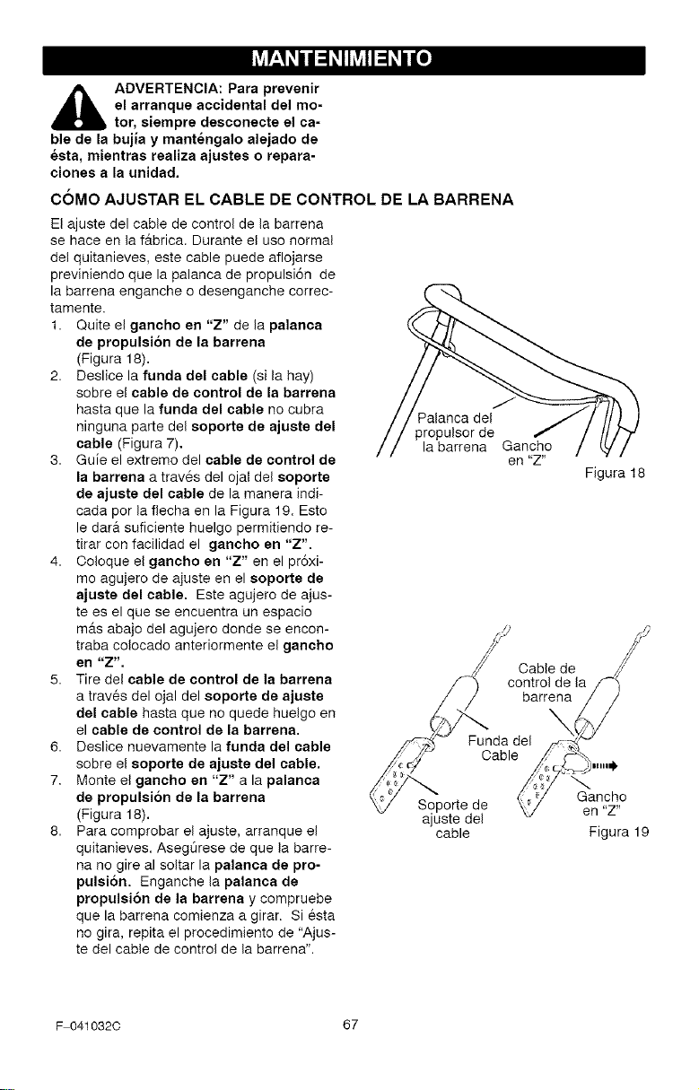
L_-' h, h, u h, o]
,_ ADVERTENCIA: Para prevenir
el arranque accidental del mo-
tor, siempre desconecte el ca-
ble de la bujJa y mantengalo alejado de
esta, mientras realiza ajustes o repara-
clones a la unidad.
C6MO AJUSTAR EL CABLE DE CONTROL DE LA BARRENA
El ajuste del cable de control de la barrena
se hace en la fAbrica. Durante el uso normal
del quitanieves, este cable puede aflojarse
previniendo que la palanca de propulsi6n de
la barrena enganche o desenganche correc-
tamente.
1. Quite el gancho en "Z" de la palanca
de propulsion de la barrena
(Figura 18).
2. Deslice la funda del cable (sila hay)
sobre el cable de control de la barrena
hasta que la funda del cable no cubra
ninguna parte del eoporte de ajuste del
cable (Figura 7).
3. Guie el extremo del cable de control de
la barrena a trav6s del ojal del soporte
de ajuste del cable de la manera indi-
cada por la flecha en la Figura 19. Esto
le dara suficiente huelgo permitiendo re-
tirar con facilidad el gancho en "Z'.
4. Ooloque el gancho en "Z" en el pr6xi-
mo agujero de ajuste en el soporte de
ajuste del cable, Este agujero de ajus-
tees el que se encuentra un espacio
m_s abajo del agujero donde se encon-
traba colocado anteriormente el gancho
en "Z".
5. Tire del cable de control de la barrena
a traves del ojal del soporte de ajuste
del cable hasta que no quede huelgo en
el cable de control de la barrena.
6. Deslice nuevamente la funda del cable
sobre el soporte de ajuste del cable.
7. Monte el gancho en "Z" a la palanca
de propulsion de la barrena
(Figura 18).
8. Para comprobar el ajuste, arranque el
quitanieves. AsegOrese de que la barre-
na no gire al soltar la palanca de pro-
pulsi6n. Enganche la palanca de
propulsi6n de la barrena y compruebe
que la barrena comienza a girar. Siesta
no gira, repita el procedimiento de "Ajus-
te del cable de control de la barrena".
Palanca del
propulsor de
la barrena Gancho
en "Z"
Figura 18
Cable de
control de la
barrena
Funda del
Cable
Soporte de
ajuste del
cable
inlll_
Gancho
en "Z"
Figura 19
F 041032C 67
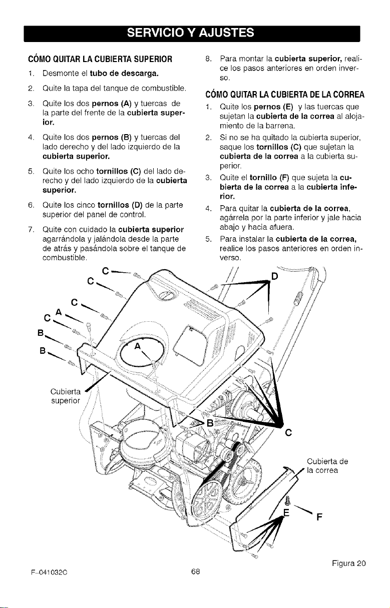
_"]=l_Ivi[o][o] h,'dP'i_llllI_"_
COMO QUITAR LA CUBIERTA SUPERIOR
1. Desmonte el tube de descarga.
2. Quite la tapa del tanque de combustible,
3. Quite los dos pernos (A) y tuercas de
la parte del frente de la eubierta super-
ior,
6,
7.
Quite los dos pernos (B) y tuercas del
lade derecho y del lade izquierdo de la
cubierta superior.
Quite los echo tornillos (C) del lade de-
recho y del lade izquierdo de la oubierta
superior.
Quite los cinco tornillos (D) de la parte
superior del panel de control.
Quite con cuidado la cubierta superior
agarr&ndola y jal&ndota desde la parte
de atr&s y pas&ndola sobre el tanque de
combustible.
8. Para montar la eubierta superior, reali-
ce los pasos anteriores en orden inver-
SO.
COMO QUITAR LA CUBIERTA DE LA CORREA
1. Quite los pernos (E) y las tuercas que
sujetan la cubierta de la correa al aloja-
miento de la barrena.
2. Si no se ha quitado la cubierta superior,
saque los tornillos (C) que sujetan la
cubierta de ia eorrea a la cubierta su-
perior.
3. Quite el tornillo (F) que sujeta la cu-
bierta de la correa a la cubierta infe-
rior.
4. Para quitar la cubierta de la correa,
ag&rrela per la parte inferior y jale hacia
abajo y hacia afuera.
5. Para instalar la cubierta de la correa,
realice los pasos anteriores en orden in-
verso.
Cubierta
superior
C
Cubierta de
F
Figura 20
F 0410320 68
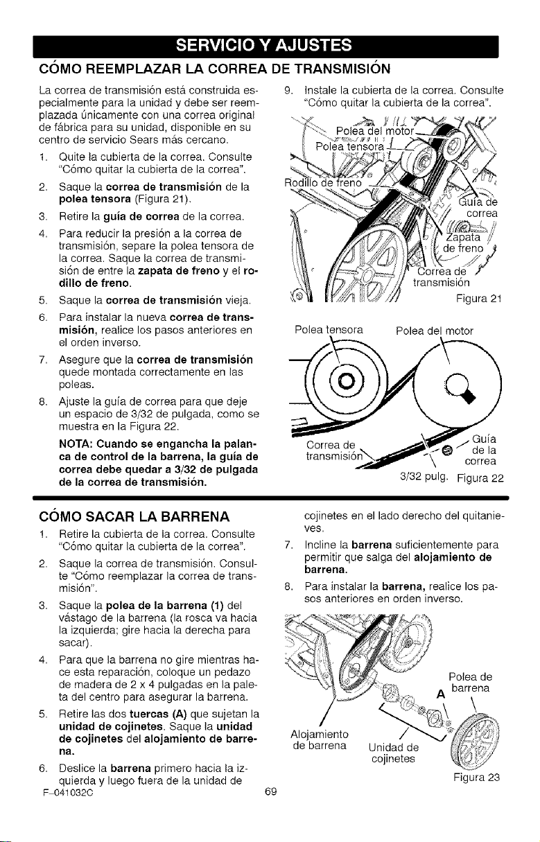
_"]=l_Ivi[o][o] h,'dP'i_llllI_"_
C6MO REEMPLAZAR LA CORREA DE TRANSMISI6N
La correa de transmisi6n est& construida es-
pecialmente para la unidad y debe ser reem-
plazada dnicamente con una correa original
de f&brica para su unidad, disponible en su
centro de servicio Sears m&s cercano.
1. Quite la cubierta de la correa. Consulte
"O6mo quitar la cubierta de la correa".
2. Saque la eorrea de tranemiei6n de la
polea teneora (Figura 21).
3. Retire la guia de eorrea de la correa.
4. Para reducir la presi6n a la correa de
transmisi6n, separe la polea tensora de
la correa. Saque la correa de transmi-
si6n de entre la zapata de freno y el ro-
dillo de freno.
5. Saque la eorrea de transmiei6n vieja.
6. Para instalar la nueva eorrea de trans-
miei6n, realice los pasos anteriores en
el orden inverso.
7. Asegure que la correa de tranemision
quede montada correctamente en las
poleas.
8. Ajuste la guia de correa para que deje
un espacio de 3/32 de pulgada, como se
muestra en la Figura 22.
NOTA: Cuando se engancha la palan-
ca de control de la barrena, la guia de
correa debe quedar a 3/32 de pulgada
de la correa de transmisi6n.
9. Instalela cubierta de lacorrea. Consulte
"O6moquitar la cubierta de la correa".
de
correa
Oorrea de
transmisi6n
Figura 21
Polea tensora Polea del motor
_6__.._. \ correa
3/32 pulg. Figura 22
C6MO SACAR LA BARRENA
1. Retire la cubierta de la correa. Consulte
"O6mo quitar la cubierta de la correa".
2. Saque la correa de transmisi6n. Consul-
te "O6mo reemplazar la correa de trans-
misi6n".
3. Saque la polea de la barrena (1) del
vastago de la barrena (la rosca va hacia
la izquierda; gire hacia la derecha para
sacar).
4. Para que la barrena no gire mientras ha-
ce esta reparaci6n, coloque un pedazo
de madera de 2 x 4 pulgadas en la pale-
ta del centro para asegurar la barrena.
5. Retire las dos tuercae (A) que sujetan la
unidad de oojinetee. Saque la unidad
de cojinetes del alojamiento de barre-
na.
6. Deslice la barrena primero hacia la iz-
quierda y luego fuera de la unidad de
F 0410320
69
cojinetes en el lado derecho del quitanie-
ves.
7. Incline la barrena suficientemente para
permitir que salga del alojamiento de
barrena.
8. Para instalar la barrena, realice los pa-
sos anteriores en orden inverso.
Figura 23
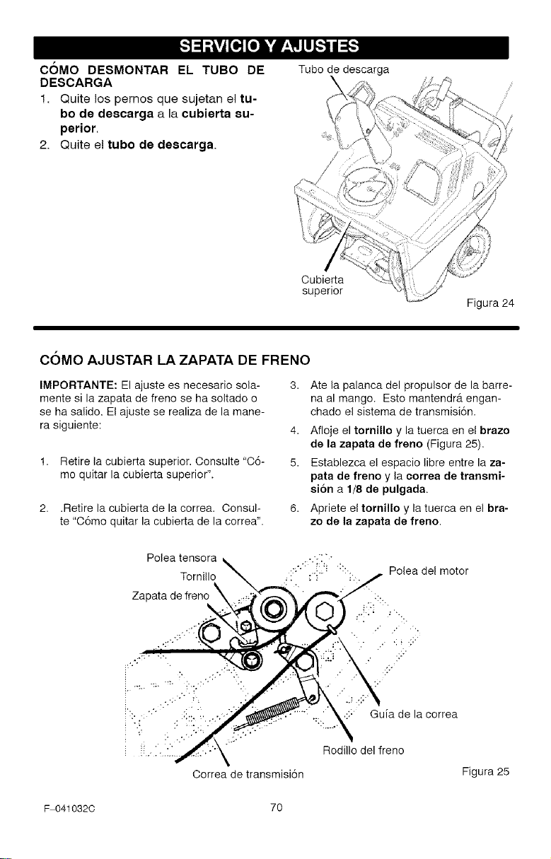
_"]=l_Ivi[o][o] h,'dP'i_llllI_"_
COMO DESMONTAR EL TUBO DE
DESCARGA
1. Quite los pernos que sujetan el tu-
bo de descarga a la ¢ubierta su-
perior.
2. Quite e! tubo de deecarga.
Tube de descarga
Oubierta
superior
Figura 24
COMO AJUSTAR LA ZAPATA DE FRENO
IMPORTANTE: El ajuste es necesario sola-
mente si la zapata de freno se ha soltado o
se ha salido. El ajuste se realiza de la mane-
ra siguiente:
1. Retire la cubierta superior. Oonsulte "O6-
me quitar la cubierta superior".
2. .Retire la cubierta de la correa. Consul-
te "O6mo quitar la cubierta de la correa".
Ate la palanca del propulsor de la barre-
na al mango. Esto mantendr& engan-
chado el sistema de transmisi6n.
4. Afloje el tornillo y la tuerca en el brazo
de la zapata de freno (Figura 25),
5. Establezca el espacio libre entre la za-
pata de freno y la eorrea de transmi-
eion a 1/8 de pulgada.
6. Apriete el tornillo y la tuerca en el bra-
zo de la zapata de freno.
Polea tensora
Tornillo
Zal
::: Guia de la correa
Rodillo del freno
Oorrea de transmisi6n
Figura 25
F 041032C 70
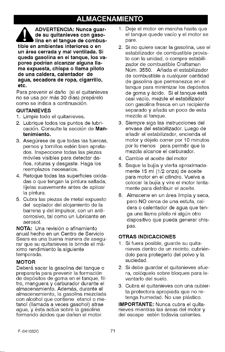
VZII?__ 0r--i_ff&17M_l_To]
,_ ADVERTENCIA: Nunca guar-
de su quitanieves con gaso-
lina en el tangue de combus-
tible en ambientes interiores o en
un area cerrada y mal ventilada. Si
queda gasolina en el tanque, los va-
pores podrian alcanzar alguna lla-
ma expuesta, chispa o llama piloto
de una caldera, calentador de
agua, secadora de ropa, cigarrillo,
etc.
Para prevenir el dafio (si el quitanieves
no se usa por mAs 30 dias) prepArelo
como se indica a continuaci6n.
QUlTANIEVES
1. Limpie todo el quitanieves.
2. Lubrique todos los puntos de lubri-
caci6n. Consulte la secci6n de Man-
tenimiento.
3. AsegL_rese de que todas las tuercas,
pernos y tornillos esten bien apreta-
dos. Inspeccione todas las piezas
m6viles visibles para detectar da-
fios, roturas y desgaste. Haga los
reemplazos necesarios.
4. Retoque todas las superficies oxida-
das o que tengan la pintura saltada;
lijelas suavemente antes de aplicar
la pintura.
5. Cubra las piezas de metal expuesto
del soplador del alojamiento de la
barrena y del impulsor, con un anti-
corrosive, tal come un lubricante en
aerosol.
NOTA: Una revisi6n o afinamiento
anual hecho en un Centro de Servicio
Sears es una buena manera de asegu-
rar que su quitanieves le brinde e! ma-
ximo rendimiento la siguiente
temporada.
MOTOR
Deber& sacar la gasolina del tanque o
prepararla para prevenir la formaci6n
de dep6sitos de goma en el tanque, ill-
tro, manguera y carburador durante el
almacenamiento. AdemAs, durante el
almacenamiento, la gasolina mezclada
con alcohol que contiene etanol o me-
tanol (llamada a veces gasohol) atrae
agua, y 6sta actLia sobre la gasolina
formando Acidos que dafian el motor.
1. Deje el motor en marcha hasta que
el tanque quede vacio y e! motor se
pare.
2. Si no quiere sacar la gasolina, use el
estabilizador de combustible provis-
to con la unidad, o compre estabili-
zador de combustible Craftsman
N0m. 3550. Afiada el estabilizador
de combustible a cualquier cantidad
de gasolina que permanezca en el
tanque para minimizar los dep6sitos
de goma y acido. Si el tanque esta
casi vacio, mezcle e! estabilizador
con gasolina fresca en un recipiente
separado y afiada un poco de esta
mezcla al tanque.
3. Siempre siga las instrucciones del
envase del estabilizador. Luego de
afiadir el estabilizador, encienda el
motor y dejelo correr per 10 minutes
per Io menos para permitir que la
mezcla alcance el carburador.
4. Cambie el aceite del motor
5. Saque la bujia y vierta aproximada-
mente 15 ml (1/2 onza) de aceite
para motor en el cilindro. Vuelva a
colocar la bujia y vire el motor lenta-
mente para distribuir el aceite.
6. Almacene en un Area limpia y seca,
pero NO cerca de una estufa, cal-
dera o calentador de agua que ten-
ga una llama piloto ni alg0n otro
dispositivo que pueda generar chis-
pas.
OTRAS INDICAClONES
1. Si fuera posible, guarde su quita-
nieves dentro de un recinto, cubri_n-
dole para proteger!o del polvo y la
suciedad.
2. Si debe guardar el quitanieves afue-
ra, col6quelo sobre bloques para le-
vantarlo del suelo.
3. Cubra el quitanieves con una cubier-
ta protectora apropiada que no re-
tenga humedad. No use plAstico.
IMPORTANTE: Nunca cubra el quita-
nieves mientras las Areas del motor y
del escape est_n todavia calientes.
F 041032C 71
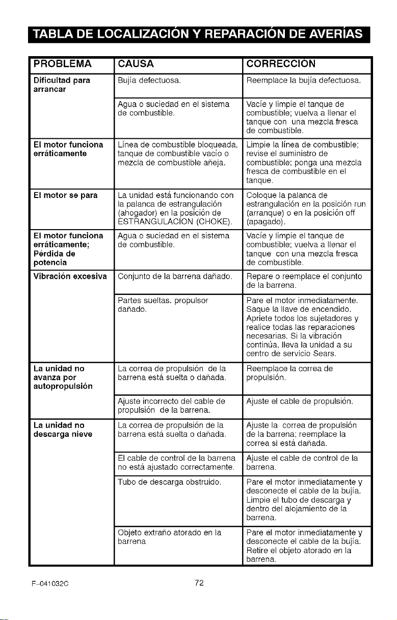
PROBLEMA CAUSA CORRECClON
Dificultad para Bujia defectuosa. Reemplace la bujia defectuosa.
arrancar
Agua o suciedad en el sistema Vacie y limpie el tanque de
de combustible, combustible; vuelva a Ilenar el
tanque con una mezcla fresca
de combustible.
El motor funciona Lfnea de combustible bloqueada, Limpie la linea de combustible;
erraticamente tanque de combustible vacfo o revise el suministro de
mezcla de combustible aheja, combustible; ponga una mezcla
fresca de combustible en el
tanque.
El motor se para La unidad ester funcionando con Coloque la palanca de
la palanca de estrangulaci6n estrangulaci6n en la posici6n run
(ahogador) en la posici6n de (arranque) o en la posici6n off
ESTRANGULAOION (OHOKE). (apagado).
El motor funciona Agua o suciedad en el sistema Vacie y limpie el tanque de
erraticamente; de combustible, combustible; vuelva a Ilenar el
Perdida de tanque con una mezcla fresca
poteneia de combustible.
Vibracion excesiva Conjunto de la barrena dafiado. Repare o reemplace el conjunto
de la barrena.
Partes sueltas, propulsor
dahado.
La unidad no
avanza por
autopropulsion
La unidad no
descarga nieve
La correa de propulsi6n de la
barrena est& suelta o dahada.
Ajuste incorrecto del cable de
propulsi6n de la barrena.
La correa de propulsi6n de la
barrena est& suelta o dahada.
Pare el motor inmediatamente.
Saque la Ilave de encendido.
Apriete todos los sujetadores y
realice todas las reparaciones
necesarias. Si la vibraci6n
contin6a, Ileva la unidad a su
centre de servicio Sears.
Reemplace la correa de
propulsi6n.
Ajuste el cable de propulsi6n.
Ajuste la correa de propulsi6n
de la barrena; reemplace la
correa si est& dahada.
El cable de control de la barrena Ajuste el cable de control de la
no ester ajustado correctamente, barrena.
Tubo de descarga obstruido. Pare el motor inmediatamente y
desconecte el cable de la bujfa.
Limpie el tube de descarga y
dentro del alojamiento de la
barrena.
Objeto extrafio atorado en la
barrena
Pare el motor inmediatamente y
desconecte el cable de la bujfa.
Retire e! objeto atorado en la
barrena.
F 041032C 72
(Estap_ginaesaplicableQnicamenteen EstadosUnidosde Am6ricay Canada.)
Sears, Roebuck and Co., U.S.A. (Sears), Junta de Recursos Ambientales de California
(CARB) y Agencia de Proteccion Ambiental de los Estados Unidos (U.S. EPA)
Declaracion de la Garantia del Sistema de Control de Emisiones (Derechos y
Obligaciones del Propietario de la Garantia de Defectos)
LA COBERTURA DE LA GARANTIA DEL CONTROL DE EMISIONES ES APLICABLE A LOS
MOTORES CERTIFICADOS QUE HAYAN SIDO COMPRADOS EN CALIFORNIA A PARTIR DE
1995 Y DESPUES DE ESTA FECHA, LOS CUALES SEAN USADOS EN CALIFORNIA, Y PARA
LOS MOTORES CERTIFICADOS MODELOS 1997 EN ADELANTE QUE SEAN COMPRADOS Y
USADOS EN OTRA PARTE DE LOS ESTADOS UNIDOS (YA PARTIR DE ENERO 1 DE 2001 EN
CANADA).
Declaracion de la Garantia de Defectos del Sistema de Control de Emisiones de
California, Estados Unidos y Canada
La Junta de Recursos Ambientales (CARB), La
Agencia de Protecci6n Ambiental de los Estados
Unidos U.S. EPA y Sears se complacen en expli-
caries la Garantia del Sistema de Control de
Emisiones de su motor pequeho modelo 2000 en
adelante para uso en terrenos sin pavimento
(SORE). En California, los nuevos motores
pequehos para uso en terrenos sin pavimento
deben ser disehados, fabricados y equipados
para cumplir los rigurosos est_tndares anti-smog
del Estado. En cualquier otra parte de los Esta-
dos Unidos, los nuevos motores de encendido
por chispa para no uso en carreteras modelos
1997 y posteriores, deben cumplir estandares si-
milares a los establecidos por la Agencia de Pro-
tecci6n Ambiental de los Estados Unidos (U.S.
EPA). Sears debe garantizar el sistema de con-
trol de emisiones en su motor por los periodos de
tiempo listados abajo, teniendo en cuenta que no
haya habido abuso, negligencia o mantenimien-
to no apropiado en su motor pequeho para uso
en terrenos sin pavimento.
Su sistema de control de emisiones incluye
partes tales como el carburador, el filtro de aire,
el sistema de encendido, el mofle y el converti-
dor catalitico. Tambi_n puede incluir conecto-
res y otros conjuntos relacionados con el
sistema de emisiones.
Siempre que exista una condici6n de garantia,
Sears reparara su motor pequefio para uso en
terrenos sin pavimento sin ningQn costo para
usted incluyendo el diagn6stico, las partes y la
mano de obra.
Cobertura de la Garantia de Defectos del Sistema de Control de Emisiones Sears
Los motores pequehos para uso en terrenos
sin pavimento se garantizan relativo a los de-
rectos de las partes del sistema de control de
emisiones durante un periodo de dos aSos, su-
jeto alas provisiones establecidas abajo. Si al-
guna de las partes bajo cobertura en su motor
se encuentra defectuosa, la parte ser_ repara-
da o reemplazada por Sears.
Responsabilidades del Propietario de la Garantia
Oomo propietario de un motor pequefio para
uso en terrenos sin pavimento, usted es res-
ponsable de que se Ileve a cabo el manteni-
miento requerido el cual se indica en sus
Instrucciones de Mantenimiento y Operaci6n.
Sears le recomienda guardar todos sus recibos
que cubran el mantenimiento en su motor
pequefio para uso en terrenos sin pavimento,
pero Sears no solo puede negar la garantia por
la falta de recibos sino pot su omisi6n al asegu-
rat la realizaci6n de todo el mantenimiento pro-
gramado.
No obstante, como propietario de un motor pe-
quefio para uso en terrenos sin pavimento, us-
ted tiene que darse cuenta que Sears puede
negarle la cobertura de la garantia si su motor
pequefio para uso en terrenos sin pavimento o
una de sus partes ha fallado debido a abuso,
F 0410320
negligencia, mantenimiento incorrecto o modi-
ficaciones no aprobadas
Usted es responsabie de presentar su motor
pequeho para uso en terrenos sin pavimento a
un Distribuidor de Servicio Autorizado Sears
tan pronto se presente el problema. Las repara-
clones bajo garantia indisputables deben com-
pletarse en un periodo de tiempo razonable
que no se exceda de 30 dias.
Si usted tiene algunas preguntas relacionadas
con los derechos y responsabilidades de la ga-
rantia, debe contactar a un Representante de
Servicio Sears marcando el tel6fono:
1-414-259-5262.
La garantia de emisiones es una garantia de
defectos. Los defectos son juzgados en el des-
empefio normal de un motor. La garantfa no es-
ta relacionada con una prueba de emisiones en
USO.
73
Provisiones de la GarantJa de Defectos del Sistema de Control de Emisiones Sears
Las siguientes son provisiones especificas re-
lativas a la Cobertura de Garantia de Defectos
del Sistema de Control de Emisiones. Es una
adici6n de la garantia del motor Sears para los
motores no-regulados encontrados en las
Instrucciones de Mantenimiento y Operaci6n.
1. Partes Garantizadas
La cobertura bajo esta garantia se extiende
Unicamente a las partes listadas abajo (par-
tes de los sistemas de control de emisiones)
hasta la extensi6n que estas partes fueron
presentadas en el motor comprado.
a. Sistema de Medici6n de Combustible
• Sistema de Enriquecimiento de
Arranque en Frio (estrangulaci6n suave)
• Carburador y Partes Internas
• Bomba de Combustible
b. Sistema de Inducci6n de Aire
• Filtro de Aire
• MUltiple de Admisi6n
c. Sistema de Encendido
• Bujia(s)
• Sistema de Encendido con Magneto
d. Sistema Catalizador
• Convertidor Catalitico
• MUltiple de Escape
• Sistema de Inyecci6n de Aire o VAlvu-
la de Pulsaci6n
e. Items Varies Usados en los Sistemas An-
teriores
• Vacio, Temperatura, Posici6n, VAlvu-
las Sensitivas de Tiempo y Suiches
• Conectores y Oonjuntos
2. Duraci6n de la Cobertura
Sears garantiza al propietario inicial y a ca-
da comprador subsecuente que las Partes
Garantizadas estaran libres de defectos en
materiales y mane de obra la cual haya oca-
sionado fallas de las Partes Garantizadas
per un periodo de dos aries a partir de la fe-
cha en que es entregado el motor a un
comprador detallista.
3. Sin Costo
La reparaci6n o cambio de cualquier Parte
Garantizada se Ilevar_t a cabo sin costo al-
guno para el propietario, incluyendo la labor
de diagn6stico la cual conduce a la determi-
naci6n de que esa Parte Garantizada es de-
fectuosa, si el trabajo de diagn6stico es
realizado en un Centro de Servicio Autoriza-
do Sears. Para servicio de garantia de emi-
siones contacte su Centre de Servicio
Autorizado Sears m&s cercano listado en
las "P_tginas Amarillas" bajo "Motores,
Gasolina", "Motores a Gasolina", "M&quinas
Cortacesped" o en una categoria similar.
4. Reclamos y Exclusiones de la Cobertura
Los reclamos de la garantia se completar_tn
de acuerdo con las provisiones de la P61iza
de Garantia del Motor Sears. La cobertura
de la garantia estar& exclufda para fallas de
las Partes Garantizadas las cuales no sean
partes originales Sears o per abuse, negli-
gencia o mantenimiento incorrecto segUn
se establece en la P61iza de Garantia del
Motor Sears. Sears no se hace responsable
de cubrir fallas de Partes Garantizadas oca-
sionadas pot el use de adici6n de partes,
partes no-originales o partes modificadas.
5. Mantenimiento
Cualquier parte garantizada la cual no est6
programada para cambio al realizar el
mantenimiento requerido o la cual este pro-
gramada Unicamente para una inspecci6n
regular per el efecto de "repare o cambie si
es necesario" se garantizar& per defectos
durante el periodo de la garantia. Cualquier
Parte Garantizada la cual este programada
para cambio per el mantenimiento requerido
se garantizar& Unicamente per defectos du-
rante el periodo de tiempo hasta el primer
cambio programado para esa parte. Cual-
quier repuesto que sea equivalente en des-
empefio y durabilidad puede ser usado al
Ilevar a cabo toda tarea de mantenimiento o
reparaci6n. El propietario es responsable
de la realizaci6n de todo el mantenimiento
requerido, segUn se define en las Instruccio-
nes de Mantenimiento y Operaci6n Sears.
6. Cobertura Consecuente
La cobertura aquf establecida se extender&
hasta la falla de cualquiera de los compo-
nentes del motor ocasionada per la falla de
cualquier Parte Garantizada que aUn se en-
cuentre bajo garantia.
F 041032C 74
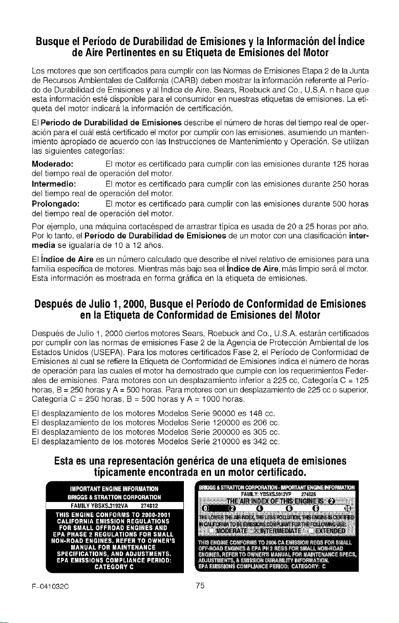
Busque el Periodo de Durabilidad de Emisiones y la Informaci6n del indice
de Aire Pertinentes en su Etiqueta de Emisiones del Motor
Los motores que son certificados para cumplir con las Normas de Emisiones Etapa 2 de la Junta
de Recursos Ambientales de California (CARB) deben mostrar la informaci6n referente al Perio-
do de Durabilidad de Emisiones y al Indice de Aire. Sears, Roebuck and Co., U.S.A. n hace que
esta informaci6n este disponible para el consumidor en nuestras etiquetas de emisiones. La eti-
queta del motor indicar_ la informaci6n de certificaci6n.
El Periodo de Durabilidad de Emisiones describe el nt_mero de horas del tiempo real de oper-
aci6n para el cu&l est& certificado el motor per cumplir con las emisiones, asumiendo un manten-
imiento apropiado de acuerdo con las Instrucciones de Mantenimiento y Operaci6n. Se utilizan
las siguientes cate( orias:
Moderado: El motor es certificado para cumplir con las emisiones durante 125 horas
del tiempo real de operaci6n del motor.
Intermedio: El motor es certificado para cumplir con las emisiones durante 250 horas
del tiempo real de operaci6n del motor.
Prolongado: El motor es certificado para cumplir con las emisiones durante 500 horas
del tiempo real de operaci6n del motor.
Per ejemplo, una m&quina cortacesped de arrastrar tipica es usada de 20 a 25 horas por afio.
Per Io tanto, el Periodo de Durabilidad de Emisiones de un motor con una clasificaci6n inter-
media se igualaria de 10 a 12 aBos.
El Jndice de Aire es un nt_mero calculado que describe el nivel relativo de emisiones para una
familia especffica de motores. Mientras m&s bajo sea el Indice de Aire, m&s limpio ser& el motor.
Esta informaci6n es mostrada en forma gr&fica en la etiqueta de emisiones.
Despu6s deJulio 1,2000, Busque el Periodo de Conformidad de Emisiones
en la Etiqueta de Conformidad de Emisiones del Motor
Despu6s de Julio 1,2000 ciertos motores Sears, Roebuck and Oo., U.S.A. estar&n certificados
per cumplir con las normas de emisiones Fase 2 de la Agencia de Protecci6n Ambiental de los
Estados Unidos (USEPA). Para los motores certificados Fase 2, el Periodo de Conformidad de
Emisiones al cual se refiere la Etiqueta de Oonformidad de Emisiones indica el nQmero de horas
de operaci6n para las cuales el motor ha demostrado que cumple con los requerimientos Feder-
ales de emisiones. Para motores con un desplazamiento inferior a 225 cc, Oategoda C = 125
horas, B = 250 horas y A = 500 horas. Para motores con un desplazamiento de 225 cc o superior,
Oategoria O = 250 horas, B = 500 horas y A = 1000 horas.
El desplazamiento de los motores Modelos Serie 90000 es 148 cc.
El desplazamiento de los motores Modelos Serie 120000 es 206 cc.
El desplazamiento de los motores Modelos Serie 200000 es 305 cc.
El desplazamiento de los motores Modelos Serie 210000 es 342 cc.
Esta es una representaci6n gen6rica de una etiqueta de emisiones
tipicamente encontrada en un motor certificado.
FAMILYYBSXS.3192VA 274812
F 041032C 75

iiiiiiiiiiiiiiii_ii_
iiiiiiiiiiiiiiii¸
iiiiiiiiiiiiiiii
iiiiiiiiiiiiiiii
iiiiiiiiiiiiiiii
iiiiiiiiiiiiiiii
iiiiiiiiiiiiiiii
iiiiiiiiiiiiiiii
iiiiiiiiiiiiiiii
iiiiiiiiiiiiiiii
iiiiiiiiiiiiiiii
iiiiiiiiiiiiiiii
iiiiiiiiiiiiiiii
iiiiiiiiiiiiiiii
iiiiiiiiiiiiiiii
iiiiiiiiiiiiiiii
iiiiiiiiiiiiiiii
iiiiiiiiiiiiiiii
iiiiiiiiiiiiiiii
iiiiiiiiiiiiiiii
iiiiiiiiiiiiiiii
iiiiiiiiiiiiiiii
iiiiiiiiiiiiiiii
iiiiiiiiiiiiiiii
iiiiiiiiiiiiiiii
Your Home
For repair -- in your home - d all major brand appliances,
lawn and garden equipment, or heating and cooling systems,
no matter who made it, no matter who sold it!
For the replacement pa_s, accessories and
owner's manuals that you need to do-it-yourself,
For Sears professionai instailation of home appliances
and items like garage door openers and water heaters
1-800_-MY_HOME ® Anylime, day or night
(1-800-469-4663) (US,A, and Canada)
www,sears,com www,sears,ca
Our Home
For repair of carry-in products iike vacuums, fawn equipment,
and electronics, cali or go on-line for the nearest
Sears Pa_s and Repair Center.
1-800488-1222 Anytme dayor night(U.S,Aonly)
WWW Seal's,cam
To purchase a protection agreement (USA.)
or maintenance agreement (Canada) on a preduct serried by Sears:
1-800-827-6655 (U&_) i-800-361-6665 (_n_a)
Para _ir _rvido de w_eparad6n Au Canada pour _'¢i_ en francis:
a domicilio y pa_ ordenar plazas:
HHHiii
HHHiii
HHHiii
HHHiii
HHHiii
HHHiii
HHHiii
HHHiii
HHHiii
iiiiiiiiiiiiiiii
_) Registered T_ademal'k £_ Trademark / _ Sewice Mark of Sears Roebuck and Ca,
_JMa_ca Registrada / *_' Marca de F_3brica/ s_ Marca de Se_v_e}o de Sea_s. Roebuck a_d Co
_4cMarine de eemmeroe / _J Marque _6pos,6e c;eSears. Roebuck and Co,