Loading ...
Loading ...
Loading ...
Electric wiring requirements
The cooker MUST be installed in compliance with:
• Wiring connections in AS/NZS3000 Wiring Rules.
• Local regulations, municipal building codes and other
statutory regulations.
• Data Plate – Gives information about the rating and
is located behind the bottom of the oven door.
• A functional switch MUST be provided near the appliance in
an accessible position (AS/NZS3000 – Clause 4.7.1).
• Wiring MUST be protected against mechanical failure (AS/
NZS3000 – Clause 3.9).
• Disconnection from the fixed wiring must occur as required by
AS3000 wiring rules.
• This range must be connected with cable of 75°C rating
minimum.
• This product has passed the insulation resistance test after
manufacture. If the resistance reading is low at installation,
it is probably caused by moisture from the atmosphere
being absorbed by the elements after the range has been
produced. (pass at 0.01MΩ AS/NZS 3000 Wiring Rules
Clause 8.3.6.2).
• The cooker MUST be properly earthed.
• When connections are made to a multiphase 230/240V
supply, the bridge piece MUST be removed from between
the active connections.
• If the supply cord is damaged, it must be replaced by
the manufacturer, its service agent or similarly qualified
persons in order to avoid a hazard.
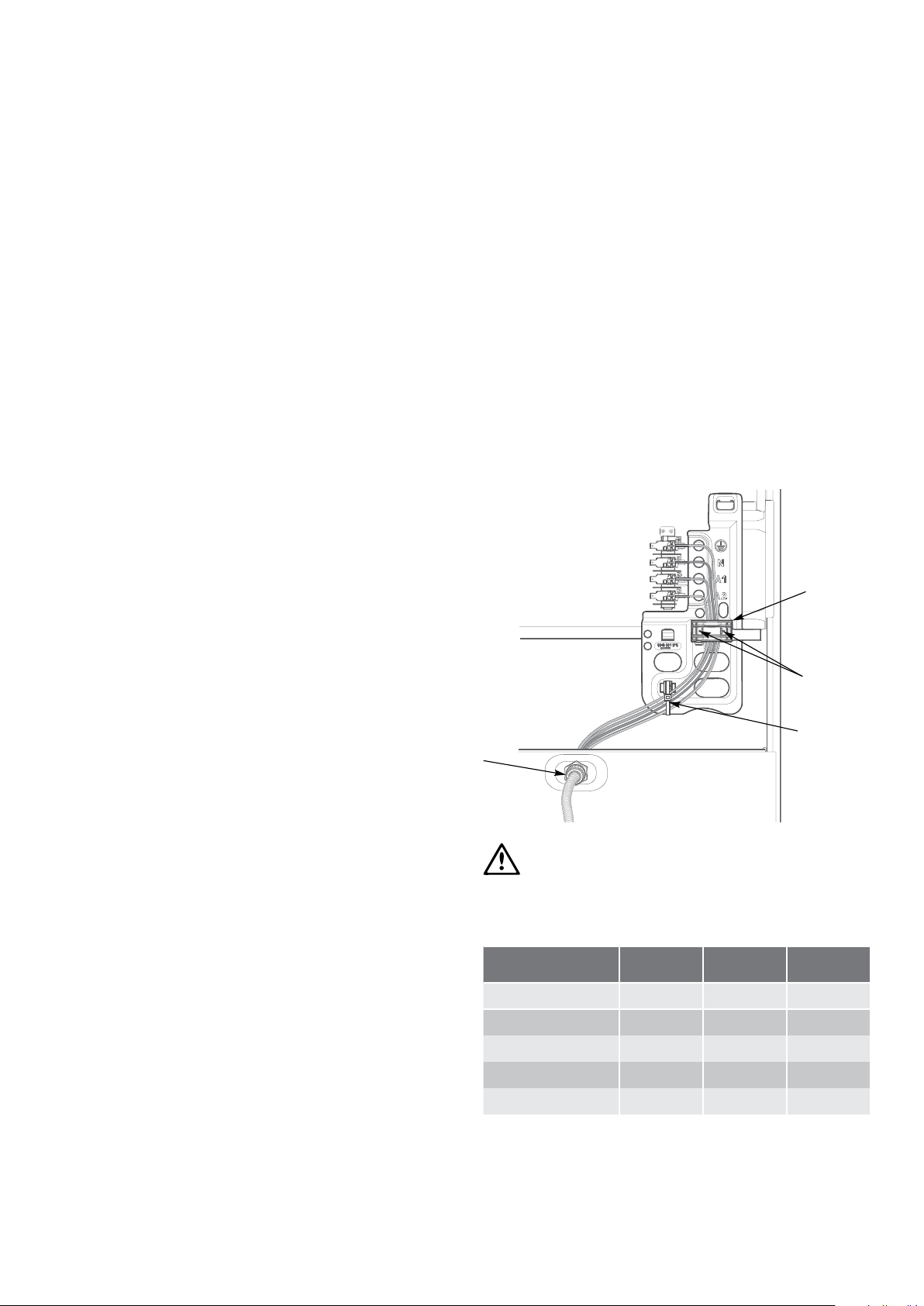
Hard wiring
1. Remove rear panel.
2. Fit wires through hole at bottom centre using the appropriate
gland to protect insulation of wires from the hole edge. Note
that the secondary insulation of the wires will probably need
to be removed to fit through gland. If the conduit to appliance
is required to bend due to rear wall an elbow may be
required to achieve this.
3. Set the length of wiring from the gland to terminal block,
ensuring length is sufficient but not excessive.
4. Make connections to terminals and engage wires into plastic
clip. Cable tie as per diagram and secure plastic clip with
two long screws supplied.
5. Replace rear cover.
WARNING
warning
Ensure wires cannot contact hot element ends or sharp edges.
Rated power input
Model Total kW A1 kW A2 kW
CFE532 8.2 2.2 6.0
CFE535 9.64 3.64 6.0
CFE536 8.2 2.24 6.0
CFE537 10.04 4.04 6.0
CFE547 9.64 4.04 5.6
installation
20 INSTALLATION Chef 540 Upright Cooker
Plastic
Clip
Plastic
clip screw
securing
points
Cable tie
Gland
Loading ...
Loading ...
Loading ...