Loading ...
Loading ...
Loading ...
—~
5
y
a
o
—
3
ee
|
fala
Ce
|
Oo
Ce
|
oun
|
Wee
+ + + + + +
+ + + + + +
SOOO
SSO,
100
437
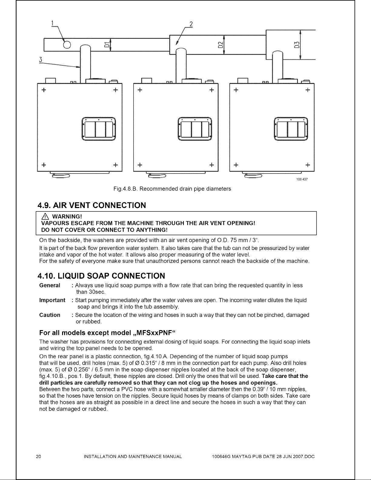
Fig.4.8.B.
Recommended
drain
pipe
diameters
4.9.
AIR
VENT
CONNECTION
Z\
WARNING!
VAPOURS
ESCAPE
FROM
THE
MACHINE
THROUGH
THE
AIR
VENT
OPENING!
DO
NOT
COVER
OR
CONNECT
TO
ANYTHING!
On
the
backside,
the
washers
are
provided
with
an
air
vent
opening
of
O.D.
75
mm
/
3°.
It
is
part
of
the
back
flow
prevention
water
system.
It
also
takes
care
that
the tub
can
not
be
pressurized
by
water
intake
and
vapor
of
the
hot
water.
It
allows
also
proper
measuring
of
the
water
level.
For
the
safety
of
everyone
make
sure
that
unauthorized persons
cannot
reach
the
backside
of
the
machine.
4.10.
LIQUID
SOAP
CONNECTION
General
:
Always
use
liquid
soap
pumps
with
a
flow
rate
that
can
bring
the
requested
quantity
in
less
than
30sec.
Important
:
Start
pumping
immediately
after
the
water
valves
are
open.
The
incoming
water
dilutes
the
liquid
soap
and
brings
it
into
the
tub
assembly.
Caution
:
Secure
the
location
of
the
wiring
and
hoses
in
such
a
way
that
they
can
not
be
pinched,
damaged
or
rubbed.
For
all
models
except
model
,,
MFSxxPNF“
The
washer
has
provisions
for
connecting
external
dosing
of
liquid
soaps.
For
connecting
the
liquid
soap
inlets
and
wiring
the top
panel
needs
to
be
opened.
On
the
rear
panel
is
a
plastic
connection,
fig.4.10.A.
Depending
of
the
number
of
liquid
soap
pumps
that
will
be
used,
drill
holes
(max.
5)
of
@
0.315"
/
8
mm
in
the
connection
part
for
each
pump.
Also
drill
holes
(max.
5)
of
@
0.256"
/
6.5
mm
in
the
soap
dispenser
nipples
located
at
the
back
of
the
soap
dispenser,
fig.4.10.B.,
pos.1.
By
default,
these
nipples
are
closed.
Drill
only
the
ones
that
will
be
used.
Take
care
that
the
drill
particles
are
carefully
removed
so
that
they
can
not
clog
up
the
hoses
and
openings.
Between
the
two
parts,
connect
a
PVC
hose
with
a
somewhat
smaller
diameter
then
the
0.39*
/
10
mm
nipples,
so
that
the
hoses
have
tension
on
the
nipples.
Secure
liquid
hoses
by
means
of
clamps
on
both
sides.
Take
care
that
the
hoses
are
as
straight
as
possible
in
a
direct
line
and
secure
the
hoses
in
such
a
way
that
they
can
not
be
damaged
or
rubbed.
20
INSTALLATION
AND
MAINTENANCE
MANUAL
100646G
MAYTAG
PUB
DATE
28
JUN
2007.D0C
Loading ...
Loading ...
Loading ...