Loading ...
Loading ...
Loading ...
4.7.
STEAM
CONNECTION
/\.
WARNING!
INSTALL
A
STEAM SUPPLY
DISCONNECTING
DEVICE
IN
THE
VINICITY
OF
EACH
WASHER.
DISCONNECT
THE
STEAM
SUPPLY
ALWAYS
BEFORE
ANY
SERVICE
OR
INTERVENTION,
GIVING
SUFFICIENT
TIME
TO
COOL
DOWN
THE
PARTS
TO
AVOID
INJUIRES.
/\
WARNING!
IT IS
NECESSARY
TO
INSERT
A
FILTER
WITH
PERMEABILITY
UP
TO
300
MICROMETERS
IN
FRONT
OF
THE
STEAM
VALVE.
POSSIBLE
DIRT
BIGGER
THAN
300
MICROMETERS
MIGHT
DAMAGE
THE
STEAM
VALVE
AND
CAN
CAUSE
ITS
LEAKAGE.
4.8.
WATER
DRAIN
CONNECTION
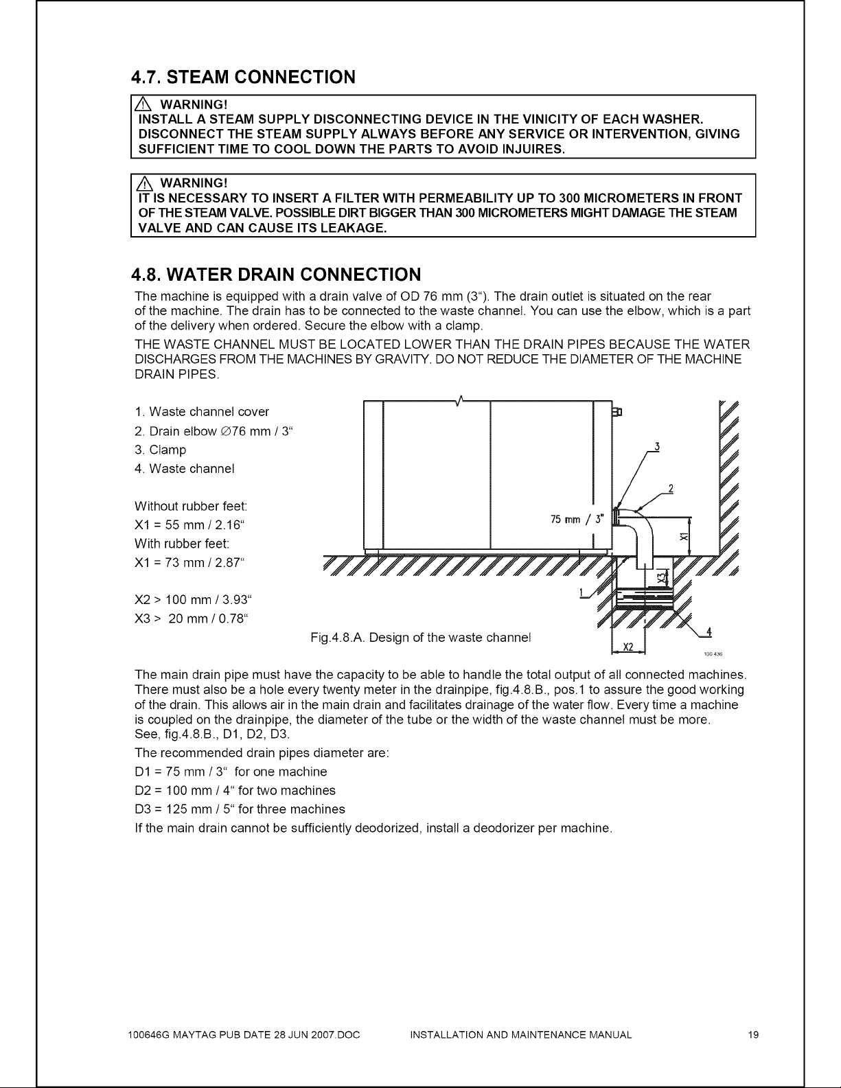
The
machine
is
equipped
with
a
drain
valve
of
OD
76
mm
(3°).
The
drain
outlet
is
situated
on the
rear
of
the
machine.
The
drain
has
to
be
connected
to
the
waste
channel.
You
can use
the
elbow,
which
is
a
part
of
the
delivery
when
ordered.
Secure
the
elbow
with
a
clamp.
THE
WASTE
CHANNEL
MUST
BE
LOCATED
LOWER
THAN
THE
DRAIN
PIPES
BECAUSE
THE
WATER
DISCHARGES
FROM
THE
MACHINES
BY
GRAVITY.
DO
NOT
REDUCE
THE
DIAMETER
OF
THE
MACHINE
DRAIN
PIPES.
1.
Waste
channel
cover
2.
Drain
elbow
@76
mm
/
3°
3.
Clamp
3
4.
Waste
channel
Without
rubber
feet:
X1
=
55
mm/2.16*
Hmm
/
3
With
rubber
feet:
X1
=
73
mm/
2.87"
7p,
X2
>
100
mm
/
3.93"
X3
>
20
mm/
0.78"
1
Fig.4.8.A.
Design
of
the
waste
channel
Xt
4
X2
100
436
The
main
drain
pipe
must
have
the
capacity
to
be
able
to
handle
the
total
output
of
all
connected
machines.
There
must
also
be
a
hole
every
twenty
meter
in
the
drainpipe,
fig.4.8.B.,
pos.1
to
assure
the
good
working
of
the
drain.
This
allows
air
in
the
main
drain
and
facilitates
drainage
of
the
water
flow.
Every
time
a
machine
is
coupled
on the
drainpipe,
the
diameter
of
the
tube
or
the
width
of
the
waste
channel
must
be
more.
See,
fig.4.8.B.,D1,
D2, D3.
The
recommended
drain
pipes
diameter
are:
D1
=
75
mm/3*
for
one
machine
D2
=
100
mm
/
4“
for
two
machines
D3
=
125
mm/
5“
for
three
machines
If
the
main
drain
cannot
be
sufficiently
deodorized,
install
a
deodorizer
per
machine.
100646G
MAYTAG
PUB
DATE
28
JUN
2007.D0C
INSTALLATION
AND
MAINTENANCE
MANUAL
19
Loading ...
Loading ...
Loading ...