Loading ...
Loading ...
Loading ...
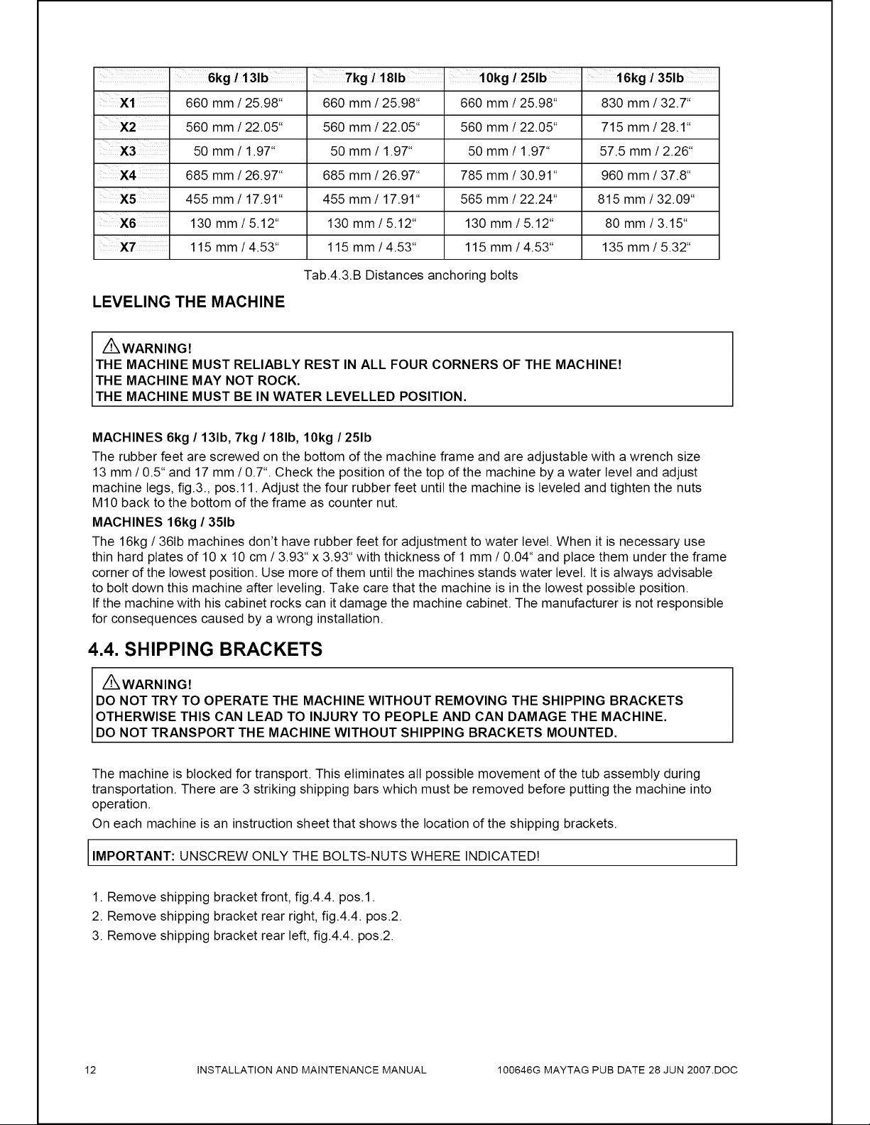
6kg
/13ib
Tkg
/
18ib
10kg
/
25Ib
16kg
/
35lb
x1
660
mm
/
25.98"
660
mm
/
25.98"
660
mm
/
25.98"
830
mm
/
32.7"
X2
560
mm
/
22.05*
560
mm
/
22.05*
560
mm
/
22.05
715
mm
/
28.1°
X3
50
mm
/
1.97"
50
mm
/
1.97"
50
mm
/
1.97"
57.5
mm
/
2.26"
X4
685
mm
/
26.97°
685
mm
/
26.97°
785
mm
/
30.91
960
mm
/
37.8"
X5
455
mm
/
17.91"
455
mm
/
17.91"
565
mm
/
22.24*
815
mm
/
32.09°
X6
130
mm
/5.12*
130
mm
/5.12*
130
mm
/5.12*
80
mm
/3.15*
XT.
115
mm
/
4.53"
115
mm
/
4.53*
115
mm
/
4.53*
135
mm
/
5.32"
Tab.4.3.B
Distances anchoring
bolts
LEVELING
THE
MACHINE
Z\
WARNING!
THE
MACHINE
MUST
RELIABLY
REST
IN
ALL
FOUR
CORNERS
OF
THE
MACHINE!
THE
MACHINE
MAY
NOT
ROCK.
THE
MACHINE
MUST
BE
IN
WATER
LEVELLED
POSITION.
MACHINES
6kg
/
13lb,
7kg
/
18lb,
10kg
/
25Ib
The
rubber
feet
are
screwed
on
the
bottom
of
the
machine
frame
and
are
adjustable
with
a
wrench
size
13
mm/0.5*
and
17
mm/
0.7".
Check
the
position
of
the
top
of
the
machine
by
a
water
level
and
adjust
machine
legs,
fig.3.,
pos.11.
Adjust
the
four
rubber
feet
until
the
machine
is
leveled
and
tighten
the
nuts
M10
back
to
the
bottom
of
the
frame
as
counter
nut.
MACHINES
16kg
/
35Ib
The
16kg
/
36ib
machines
don’t
have rubber
feet
for
adjustment
to
water
level.
When
it
is
necessary
use
thin
hard
plates
of
10
x
10
cm
/
3.93"
x
3.93*
with
thickness
of
1
mm
/
0.04“
and
place
them
under
the
frame
corner
of
the
lowest
position.
Use
more
of
them
until
the
machines
stands
water
level.
It
is
always
advisable
to
bolt
down
this
machine
after
leveling.
Take
care
that
the
machine
is
in
the
lowest
possible
position.
If
the
machine
with
his
cabinet
rocks
can
it
damage
the
machine
cabinet.
The
manufacturer
is
not
responsible
for
consequences
caused
by
a
wrong
installation.
4.4.
SHIPPING
BRACKETS
Z\
WARNING!
DO
NOT
TRY
TO
OPERATE
THE
MACHINE
WITHOUT
REMOVING
THE
SHIPPING
BRACKETS
OTHERWISE
THIS
CAN
LEAD
TO
INJURY
TO
PEOPLE
AND
CAN
DAMAGE
THE
MACHINE.
DO
NOT
TRANSPORT
THE
MACHINE
WITHOUT
SHIPPING
BRACKETS
MOUNTED.
The
machine
is
blocked
for
transport.
This
eliminates
all
possible
movement
of
the tub
assembly
during
transportation.
There
are
3
striking
shipping
bars
which
must
be
removed
before
putting
the
machine
into
operation.
On each
machine
is
an
instruction
sheet
that
shows
the
location
of
the
shipping
brackets.
IMPORTANT:
UNSCREW
ONLY
THE
BOLTS-NUTS
WHERE
INDICATED!
1.
Remove
shipping
bracket
front,
fig.4.4.
pos.1.
2.
Remove
shipping
bracket
rear
right,
fig.4.4.
pos.2.
3.
Remove
shipping
bracket
rear
left,
fig.4.4.
pos.2.
12
INSTALLATION
AND
MAINTENANCE
MANUAL
100646G
MAYTAG
PUB
DATE
28
JUN
2007.D0C
Loading ...
Loading ...
Loading ...