Loading ...
Loading ...
Loading ...
ELECTRmCAL CONNECTIONS
WARNING: MAKE SURE THE UNIT IS "OFF" AND
DISCONNECTED FROM THE POWER SOURCE
BEFORE INSPECTING ANY WIRING.
Themotor and wiring are installed as shown in the wiring
diagram (See Figure 1).
Themotor isassembled with an approved three-conduc-
tor cord to be used on 120 volts as indicated.
The power supply to the motor iscontrolled by a double-
pole rocker switch.
Remove the key to prevent unauthorized use.
The power lines are attached to the switch with quick
connect terminals.
The green ground line must remain securely fastened to
the frame to properly protect against electric shock.
A manual reset overload protector isinstalled in line with
the power supply to the motor. If the planer isoverloaded
the protector will break the circuit.
tf the circuit breaker istripped, turn the planer "off" and
reset the circuit by pressing the button.
@
CIRCUIT
BREAKER
REEN
(GROUND)
Figure 1
CAUTION: BE SURE TO TURN THE PLANER "OFF"
PRIOR TO RESEN'ING THE CIRCUIT BREAKER TO
AVOID UNINTENTIONAL START-UP OF THE PLANER.
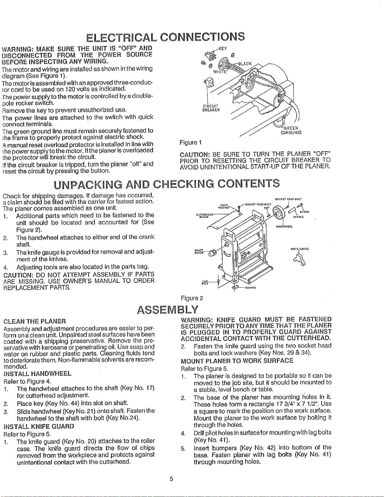
UNPACKING AND CHECKING CONTENTS
Check for shipping damages. If damage has occurred,
a claim should be filed with the carrier for fastest action. _oo,,_...... _T
The planer comes assembled as one unit.
1. Additional parts which need to be fastened to the
unit should be located and accounted for (See
Figure 2),
2. The handwheel attaches to either end of the crank
shaft.
3. The knife gauge is provided for removal and adjust- *.........!
ment of the knives. _
4. Adjusting tools are also !ocated in the parts bag.
CAUTION: DO NOT ATTEMPT ASSEMBLY IF PARTS
ARE MISSING. USE OWNER'S MANUAL TO ORDER
REPLACEMENT PARTS.
CLEAN THE PLANER
Assembly and adjustment procedures are easier to per-
form on a clean unit. Unpainted steel surfaces have been
coated with a shipping preservative. Remove the pre-
ser,,ative with kerosene or penetrating oil. Use soap and
water on ruboer and plastic parts. Cleaning fluids tend
to deteriorate them. Non-flammable solvents are recom-
mended.
INSTALL HANDWHEEL
Refer to Figure 4.
1. The handwheel attaches to the shaft (Key No. 17)
for cutterhead adjustment.
2. Place key (Key No. 44) into slot on shaft.
3. Slide handwheel (Key No. 21) onto shaft. Fasten the
handwheel to the shaft with bolt (Key N0.24).
INSTALL KNIFE GUARD
Refer to Figure 5.
1. The knife guard (Key No. 20) attaches to the roller
case. The knife guard directs the flow of chips
removed from the Workpiece and protects against
unintentional contact with the cutterhead.
Figure 2
ASSEMBLY
WARNING: KNIFE GUARD MUST BE FASTENED
SECURELY PRIOR TO ANY TIME THAT THE PLANER
IS PLUGGED IN TO PROPERLY GUARD AGAINST
ACCIDENTAL CONTACT WITH THE CUTTERHEAD,
2. Fasten the I_nife guard using the two socket head
bolts and lock washers (Key Nos, 29 & 34).
MOUNT PLANER TO WORK SURFACE
Refer to Figure 5.
1. The planer is designed to be portable so it can be
moved to the job site, but it should be mounted to
a stable, level bench or table.
2. The base of the planer has mounting I_oles in it.
These holes form a rectangle 17 3/4" x 7 1/2". Use
a square to mark the position on the work surface.
Mount the planer to the work surface by bolting it
through the holes.
4. Drill pilot holes in suffacefor mounting with lag bolts
(Key No. 41).
5. Insert bumpers (Key No. 42) into bottom of the
base. Fasten planer with lag bolts (Key No. 41)
thi'ough mounting holes.
Loading ...
Loading ...
Loading ...