Loading ...
Loading ...
Loading ...
English
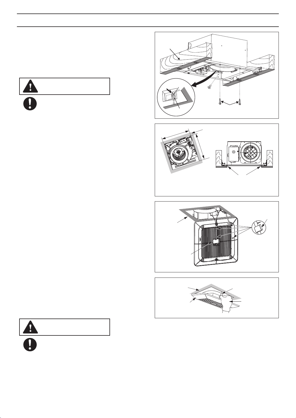
10. Insert the grille mounting spring on the wiring
side into the slot. (Fig.8)
13. Insert the other mounting spring into the slot as
shown and mount grille to fan body. (Fig.9)
12. Adjust Pick-A-Flow switch.(Refer to indication on
FEATURE)
9. Finish ceiling work. Ceiling hole should be aligned
with the inside edge of the flange. (Fig.7)
Mount grille carefully so that lead wire is not
pinched.
CAUTION
10 1/2
(270)
10 1/2
(270)
Fig.7
Unit: inches (mm)
After finishing the ceiling job, fill gap between flange
and ceiling with caulk or other sealant to prevent air
leakage
Ceiling
8. Insert fan body and slide into adapter assy
with some strength, until the flange overlaps
the Flex-Z Fast bracket. Secure the fan
body to Flex-Z Fast bracket by using 2
self-drilling screws, plug connector to
receptacle and secure the fan body to adaptor
by using machine screw (M4X8). (Fig.6)
TM
TM
Secure machine screw (M4X8) to the
suitable hole and not touch the Flex-Z
Fast bracket. Please fix the screw
carefully to avoid screw slip teeth.
TM
Machine
screw
(M4X8)
2 Self-drilling
screws
Joist
Plug connector
Receptacle
Fig.6
CAUTIONCAUTION
INSTALLATION (NEW CONSTRUCTION) CONTINUED
Ceiling
Fig.8
Clasp
9
11. Insert the motion sensor on the grille and dress
the wire as shown. (Fig. 8)
Motion Sensor
(FV-0511VQC1
only).
Fig.9
Grille
Ceiling
Gloves
Mounting spring
Loading ...
Loading ...
Loading ...