Loading ...
Loading ...
Loading ...
English
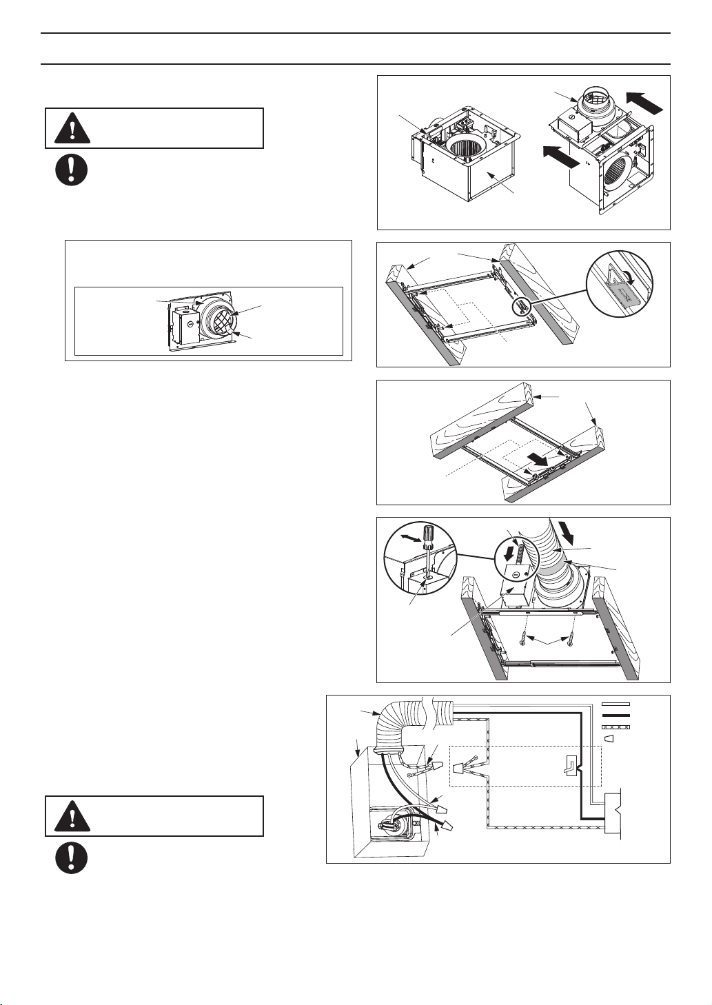
2. Bend down 4 tabs for positioning, install the
Flex-Z Fast bracket to joists by drilling 2 tapping
screws which have been fixed on it. (Fig.2)
TM
TM
3. Adjust the length of Flex-Z Fast bracket as the
spacing between joists, and install to joists by
drilling the other 2 tapping screws which have
been fixed on it. (Fig.3)
4. Remove junction box cover and secure conduit
or stress relief to junction box knock-out hole.
(Fig.4)
TM
6. Install the adaptor to Flex-Z Fast bracket by
using 2 self-drilling screws. (Fig.4)
5. Install a circular duct and secure it with clamps,
or ties and seal it with mastic or approved foil tape.
A 4 or 6 inch circular duct is needed to connect to
relevant part of adaptor. (Fig.4)
Fig.2
Mount junction box cover carefully
so that lead wires are not pinched.
7. Refer to WIRING DIAGRAM.
Follow all the local electrical safety codes
as well as the National Electrical Code (NEC).
Using UL approved wire nuts, connect
house power wires to ventilating fan wires.
(Fig.5)
2 Tapping screws
(ST4.2X20)
Bend down
4 tabs
Joist
Fig.3
Joist
2 Tapping screws
(ST4.2X20)
2 Self-drilling screws
Knock-out
hole
Junction box
cover
Conduit
Circular duct
Mastic or
approved
foil tape
Fig.4
INSTALLATION (NEW CONSTRUCTION)
Fan body
Adaptor
Fig.1
Machine screw
(M4X8)
The fan position between joists from 16" to 24"
on center can be adjusted flexibly.
Please wear gloves during the installation
work as follow.
CAUTION
machine screw (M4X8) before installation. (Fig.1)
IMPORTANT:
Remove the tape from damper and adaptor
before installation. As shown below:
Tape
Adaptor
Damper
CAUTION
Fig.5
BLACK
WHITE
GREEN
Wire nuts
Junction
box
L
N
120 VAC
LINE IN
Switch box
Conduit
Earth ground
Earth ground
Live
Neutral
8
1. Disconnect plug connector from receptacle (Fig.6)
and remove adaptor from fan body by removing the
Loading ...
Loading ...
Loading ...