
MODELS, MODELOS:
order to prevent
or "mprop_
any damages
,o
FOR YOUR RECORDS,
Wrile the m_el and _ria_ humors here:
Model #
Serial #
You can find them on a _abel on the side of each unit,
_aler's Name
Date Pulrct,ased
• Slaple your receipl !o this page ir_the event you need
it to prove date d put€haste or for warranty issues.
READ THIS MANUAL
Inside you wi!l find many !helpf_;I hinls on how to use
and mainlain your a_r conditioner pre_rly Just a little
prevenlive care on your part can save you a great deal
of time and money over the life of your a_r_onditioner,
You_l_find many answers to _mmon problems 'n the
cX_arlof troublesh_ling tips If you review our char1 d
Troubleshooting Tips first you may not need to cal_
Norservice at all,
PRECAUTION
. Contact the auth_ized s_i_ technician for r',_
_mtenan_ of this unit.
, C_ct the instal_r for instal_ion of this unit,
• _e air cond_i_ is not intended f_ gse by yogng
chi_ren _ invalids w_hout _vl_.
• Young children should be _psrvi_d to ensure that
they do n_ play w_h the air condition_,
• When the power c_d is to _ replaced, replacement
work shall _ _orrn_ by auth_iz_ _rsonne_ on_
u_ng _ly g_uine rep,la_nt_nt pa_s,
• _stal_tien w_ mu_ _ pedorrr_d in a_ordian_ with
_e National _le_ie Co_e by ,qga_ _nd authored
per_nel on|y_
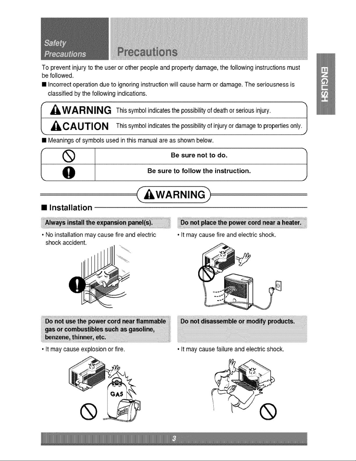
To prevem [niury to the user or other people ar_ pro_rty _mage, the following instructions must
be followed,
• incorrect o,_ration due to ignodng instwct[on will cause harm or _mage, The seriousness is
c]a_ifiied by the folio,wing indicator's.
[] Installation
• No installation may cau_ fire and electric
shock accident.
• it may cause fire and eie,ctr[,c shock
• it may _use explosion or fire. • lit may cause fa[liure and electdc shock.
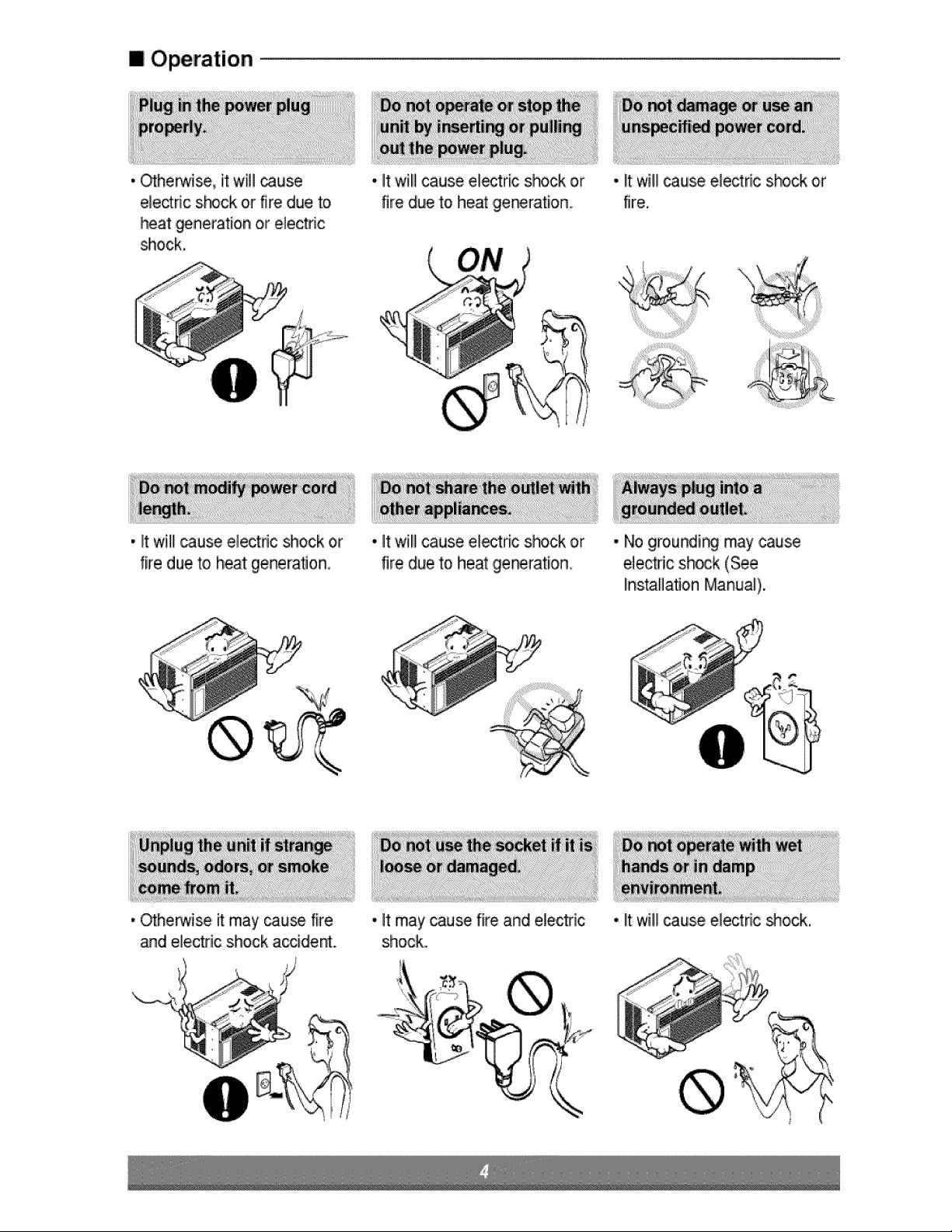
i Operation
, Otherwise, it wil! _use
ele_dc s_ck or fire due to
heat generation_or electric
_ock,
• It will cause electdc _ock or
fire due to heat generation.
• Othe_ise it may cau_ fire
and electlic shock accident.
• it wil!lcause eiectric shock or
fire due to heat ,get.ration.
, I!twill! cause electdc shock or
fire.
, It will cause electric shock or
fire due to heat gestation
o It may cau_ fire and electdc
shock.
• No groundir,_ may cause
etectdc shock (See
installation Manual).
• lit will _use electdc shock.
• It w[li]cau_ failure of machine
or ele_dc s_ck.
• it is not designed to c_] _e
entire house.
• It may cause explosion, fire,
and burn.
[] installation
CAUTION jh
• They are sharp and may
causeinju_
• It may cause injury.
• It may cause failure of
applance or a_idenL
• ff leaving appliance damaged,
there is concern of damage
due to the falling of product.
i Operation
• it may cause electric shock • Prevent accidental s,ta_up
a_ damage, and the possi_lity of injury,,
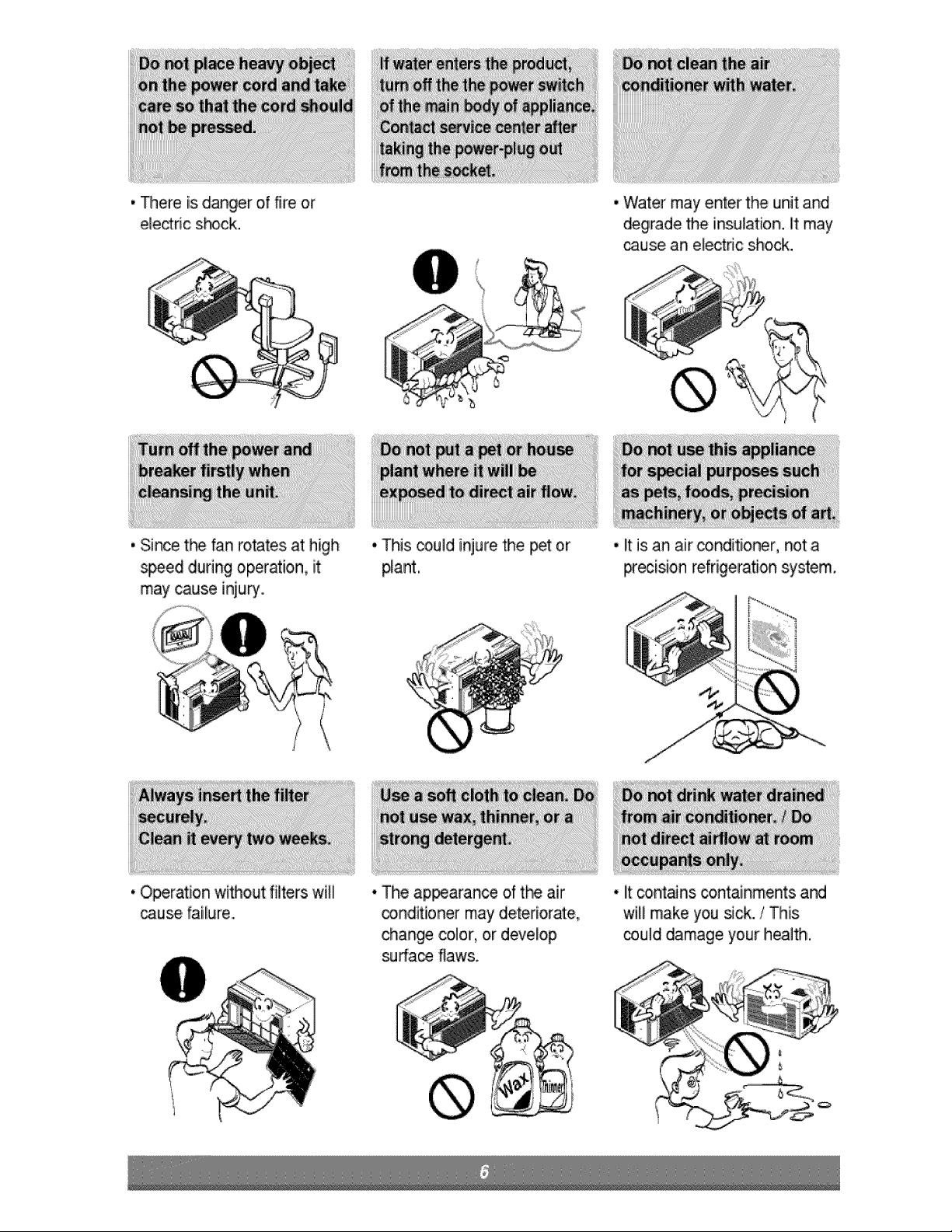
, Thereis danger of fire, or
e_eddc shock.
. Water may enter the unit and
degrade the insulation, it may
_use an electric shock.
, Since t_ fan rotates at high
_ed during operation, iit
may cause injury.
. Operation without filters willi
_us,e faiiliure,.,
• This _uld injure the pet or
pla,nt.
, It is an air conditioner, not a
p_ecisionrefrigeration system.
• The ap_arance of t_ .air
conditioner may deteriorate,
change color, or develop
surfa_ flaws.
, litco,ntans containments and
wilil make you sick./This
_uid damage your health.
_ Contact an installation spec:ialistfor installaSon
Piug in _e power plug properly,
_Do not share _e same outlet wi_ o_er appliances
Do not use an extension _rd
Do not sta_'stop operation by p_ugging/unp_uggingthe _wer cord,
_lf cordipllug is ,damaged,replace only with an authorized part
iI i_ii_
Being ex_sed to direct airflow for an extended period of time oouid be hazardous to your hea_thoDo not
expose o_upants, _, or pian_ to direct allow for extend_ pedods of time,
Due to the _ssibi/ity of oxygen deficiency, ventJl_e _e room when using t_ether with stoves or other
Do not use this ;aircondi_oner for nomspecified special purposes (e.g preserving precision devices,
food,,pets, plants, and a_-tobiects) Usage in such a manner could harm such property,
Do not:touc:hthe metal parts of the unit when removing the filter Iniuries can occur when handling sharp
metal edges,
Do not use water to clean inside the air conditioner Exposure to w_ter can destroy #_e insula'_on leading
to possible e_iectricsh_k,
When c_eaningthe unit, first:make sure that the power and breaker are turned off:. The fan rotates at a
very high speed dudng o_ration, There is a possibili_ of iniu_ if the unit's _wer is accidentally
_ggered on while c!eaning inner pa_s of the unit,
For repair and maintenance contact your authoriz_ ser,4ce deaier,
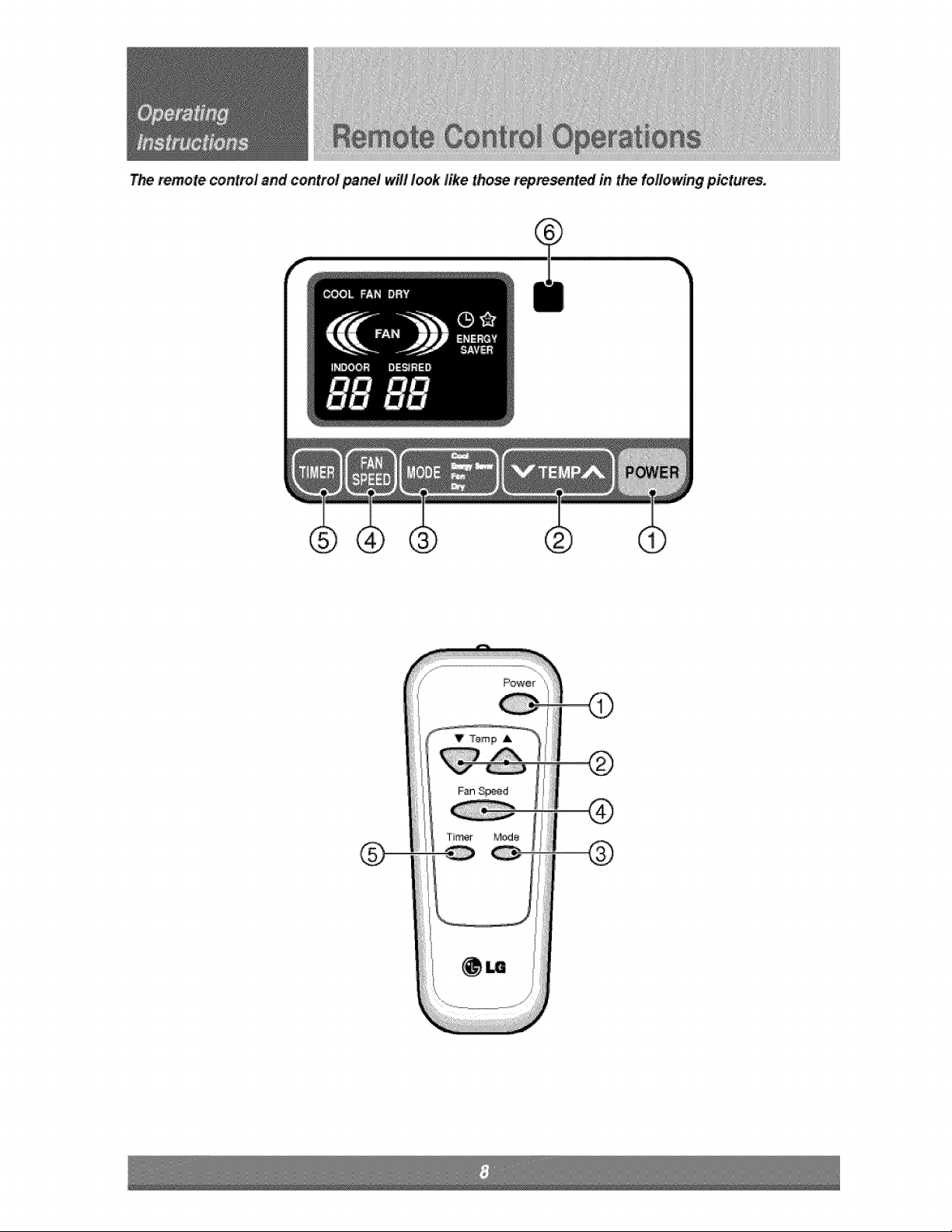
T_ mmote control and control pa_/ will look like those repre_nt_ in t_ fo//owin,gpictures=

PO,W_
C#eralion starts when this button is press_ and
s_ops w_n you press the button again.
_r_iPERATUR:E CON_OIL
T_ thermostat monitors room temlperature to
mai_ain _e desired temperature
T_ thermostat can be sel between 60°F_86°F
T_ unit takes an average of 30 minutes to adjus_ the
r_m temperature by !
OPEIRATIiON _DE _LE,C:TOR:
Select coolir_9 mode to ooo_the room
Select: energy saver mode _Orenergy _ving
Select fan mode for basic ventilating fan operation.
Sele_ dry mode _or dPf operation.
FARSPEED,SELECTOR
For increased power while coo_ing select a higher
fan speed.
3 steps: High -.>Low e Med
ONiOFF TIMER
The timer can be _t to star'I a._ stop t_ uni'tin
increments (up to 12 hours}.
REMOTE CON_OL SENSOR
_,_ Push out the cover on the back of:the [remote control with you_thumb
/_ Pay attention to polarity and insert two r'_ewAAA 1.EV _l:teries.
Reatiaoh tlhe cover.
" Do not use rech_gieable batteries,,M_e sure that both batteries are new,
• _nordertopteven4d_<harge,retake_e ba_et_sfrom£heremote_ntt_ #theair_nd_bnetB notgoingto
u_d forane_e_d _bd ,dtime
K_p the_emotecontrolawayfrome_re_iy hotor humidp!ace_,
Tot_i_i_ @flmal@er_n d _,ere_r_ece_el the_emote_sor sh_d _etbee×_ed todirectsu_iigi'_
•_e remote_at_olca__ m_nt_ o_awa#lusiagthei_u_i_blehol@_,_
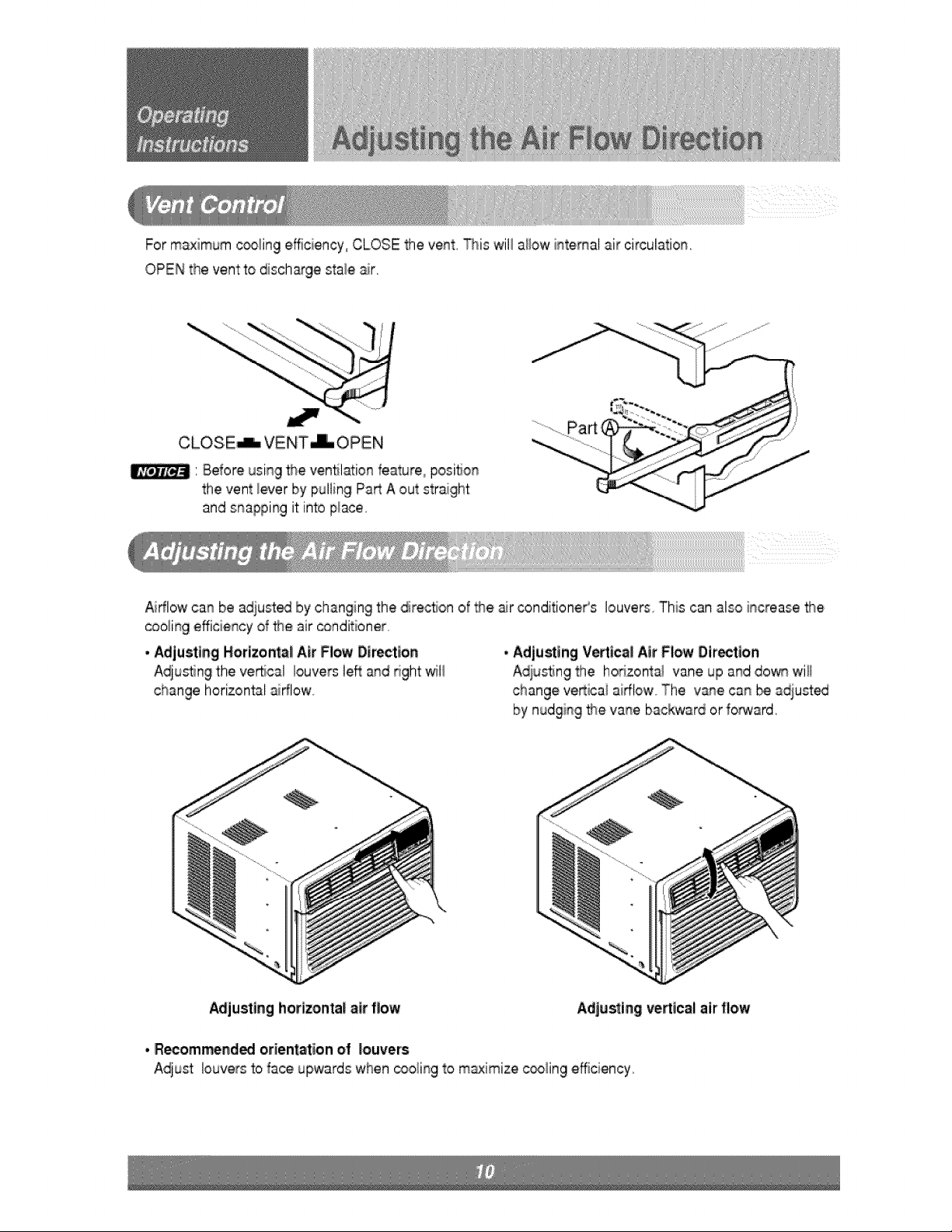
Formaximum_ling efficiency,, CLOSE the vent. _is will allow intemat air circulation.
OPEN the ventto disch_ge stalie air.
CL,OSiE_ VENT_ OPEN
' Before using the ventil_ion feature, posi_on
the vent _everby pulling Pa_ A out straiight
and snapping it into place.
Aidlow can be adiust_ by changing the direction of _e air conditioneCs louvers. This can also increase 9_e
coo_ingefficiency of _e air _onditioner
* Adjusting H,orizont,a!Air Flow Direction
Adjusting the vertical iouvers left and right _li
horizontal airflow.
* Adjusting Vertical Air Flow Oirection
A,dius_ngthe hodzontai vane up and dow_ will
change ve_icai aiff!ow The vane can _ adjusted
by nudging _e vane backward or forward.
Adjusting horlzo,nta! air flow Adjuring vertical air flow
• R_om_ndi_ orientation of Iouver's
Adjust louvers to face upwards when _oling to m_imize c_ling effi,ciiency
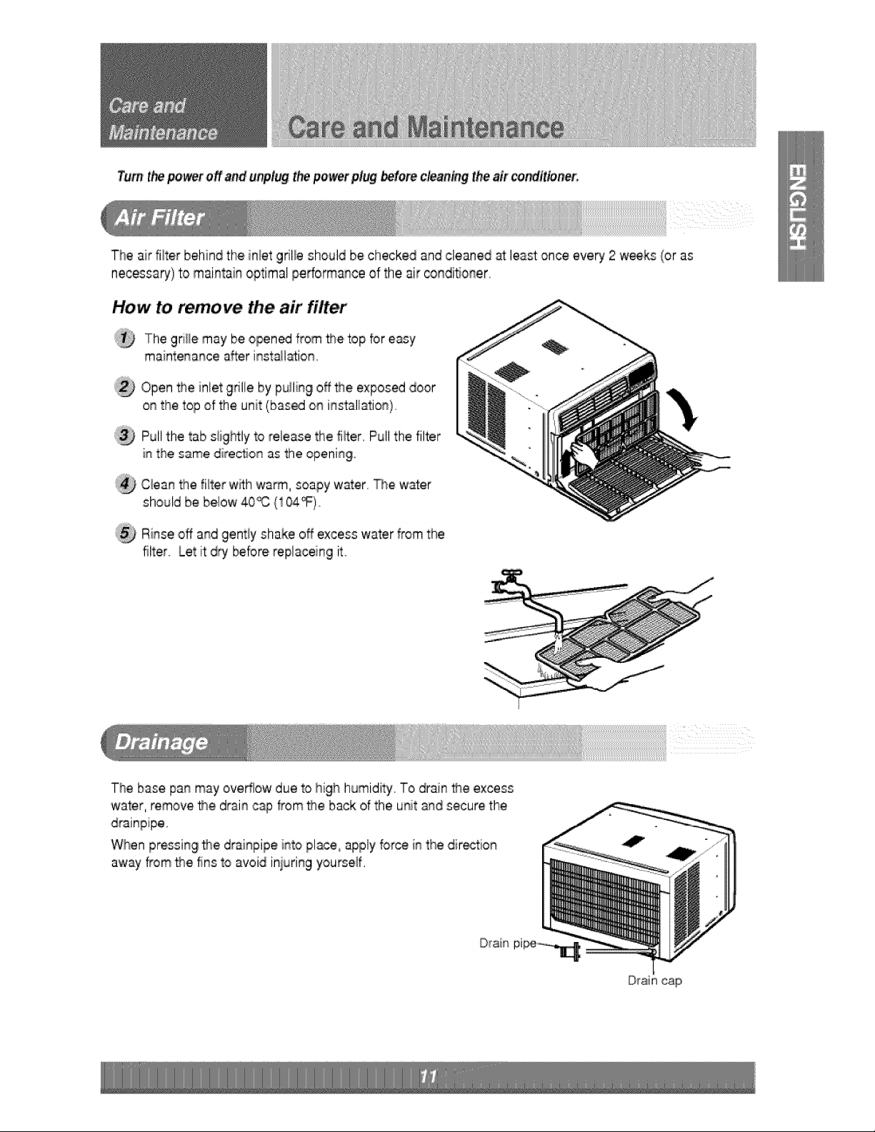
Turn thepo,_t off and unpl_ th_ powerplug _,to,re cleaning the air condtt_net,
The air filter behind the inlet grille should be checked and cleaned _ least once every, 2 weeks (or as
necessa_) to maintain optimal performance of the air _ndiSoner,
How to remove the ,air filter
®
®
®
®
The grille may be opened from me top for easy
maiintenance after insta_l_ion,
Open the nlet grille by pulling off #}e exposed door
on the top of the unit (based on installation),
Pui!the tab siightiy to release the fi_ter,Pu!l the filter
iL_the same dire,croonas the ,openingi.
C:_eanthe fi_terw_lhwarm, soapy water, _e water
should be [below40'_ (104_)
Ri_se off and gently shake off excess water from the
filter. Let it dry bebre replaceing it
The base pan may overflow due to Ihighhumidity. To drain _,e excess
water, remove _,e drain cap from the back of the unit a_,dsecure the
When pressing fl_e drainpipe into place, apply force in the dir_tion
away from f_e fins to avoid iniuring yourse#,
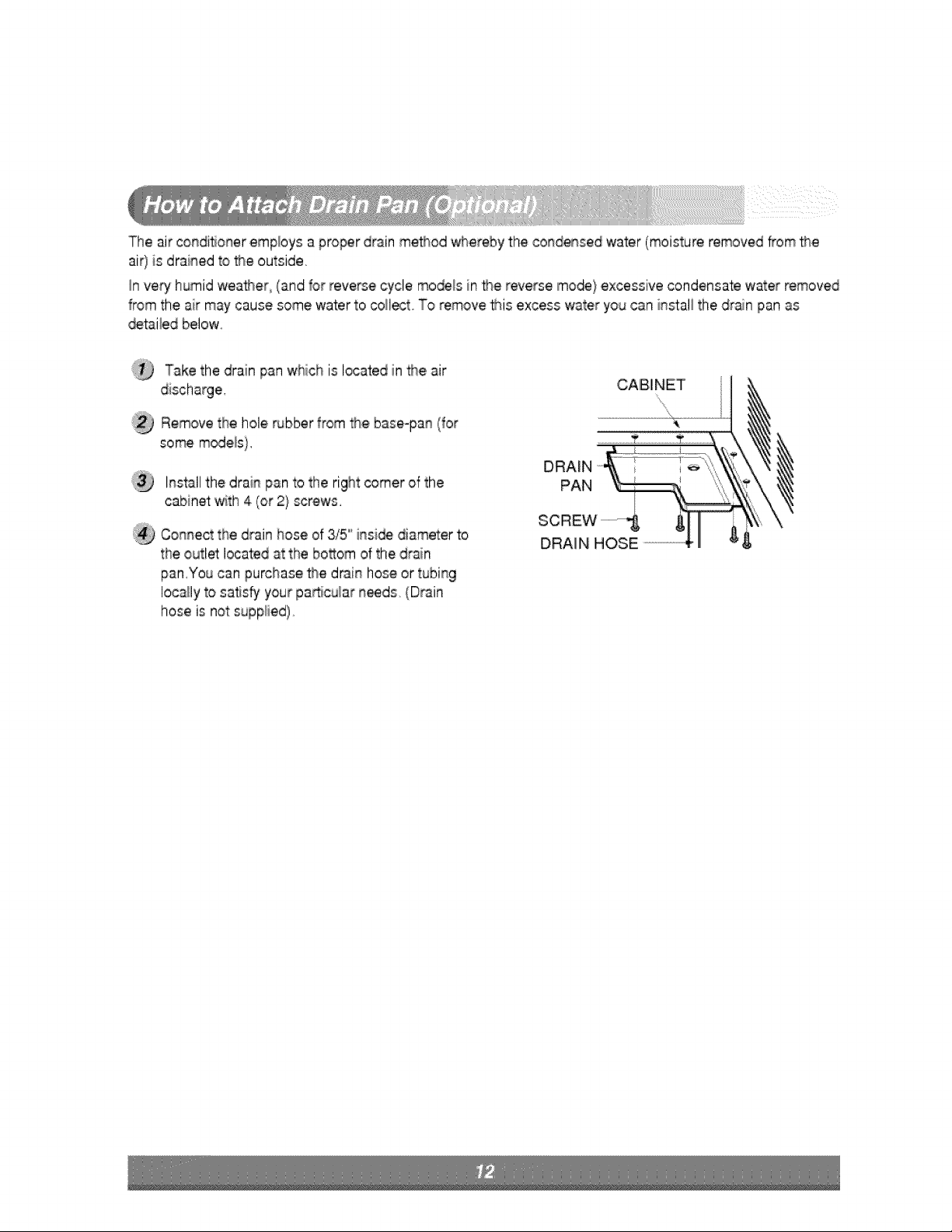
Theairc,o_dit_oneremploysaproperdrainmethodwherebythecondensedwater(moistureremovedfrom_e
ai0 isdrainedto'_eoutside,
_nveryhumidwea_er,(andforreversecyclemo_lsinthereversemode}excessivecondensatewaterremoved
fromtheairmaycausesomewatertocoilectToremove#_isexcesswateryoucaninstallthedrainpanas
_t_iledbelow°
TakethedrainpanwhichislocatedinDeair
Removetheholerubberfrom_,ebase-pan(for
so_ models}.
Installthedrainpantotherightcomerofthe
cabinet_th4(or2}screws.
Connectthedr'sinhoseof3/5"insi_ diameterto
theoutietlocatedatthebosomofthe,drain
pan,You can purchase the drain hose or tubing
locally to satisfy your pa_cu_ar n_ds (Drain
hose is not supplied),
CA IB,IN ET
DRAIN
PAN
SCREW
DRAI N HOSE
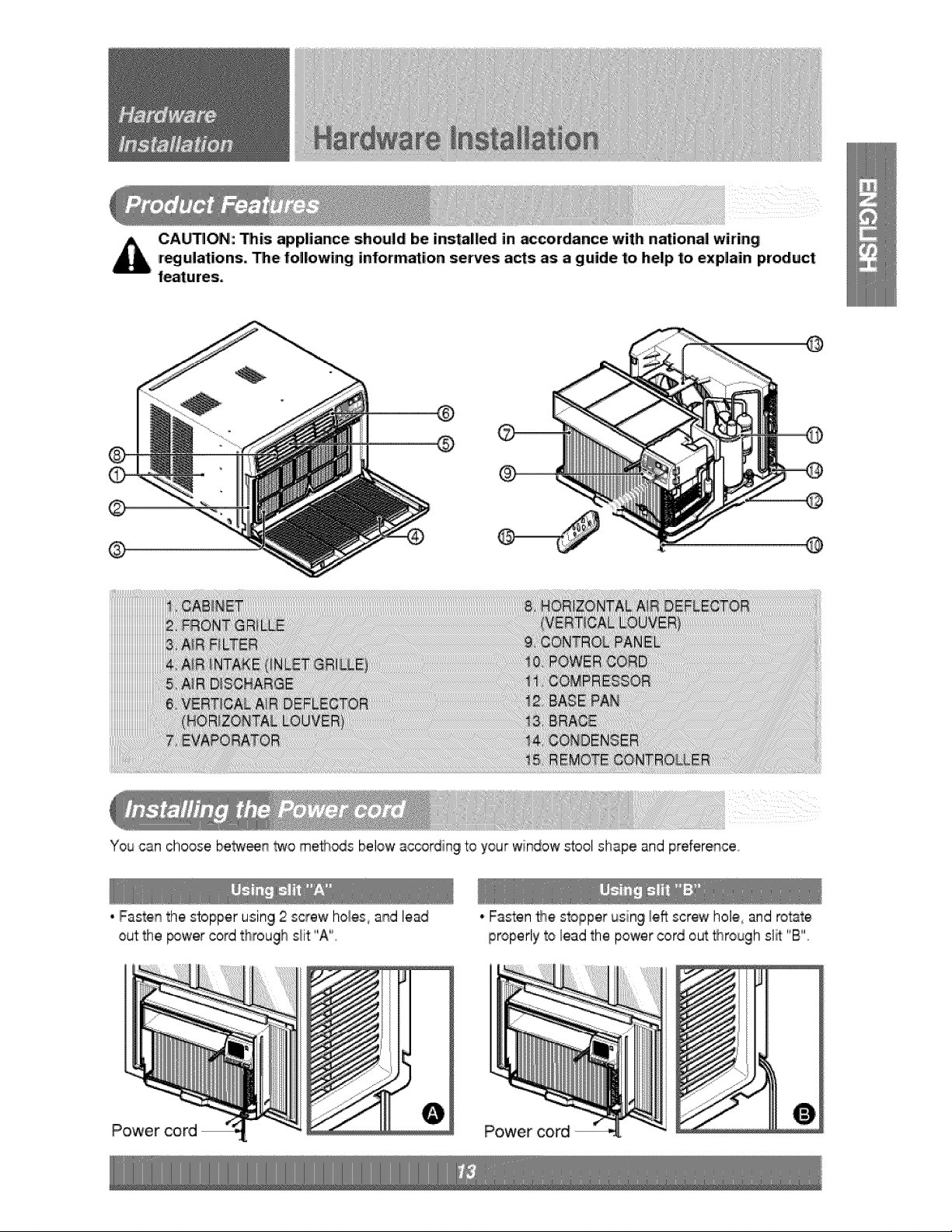
CA_ON: his app,liance should be ins_l|ed in _cordance with national wiring
r_ulationso he fol|owing information serves a_s as a guide to, help to, explain product
features,
@
®
®
®
You can choose betw_n _o me_s below ac_rding to your window _oo! shape and preference,
• Fastenthe stopper using 2 screw hol,e,s,and lead
out the _wer cord through s_it"A"
Power cord
* Fasten _e stopper using I,e_screw hole,,and rotate
properly to lead the power cord out _rough slit "B"
Power cord
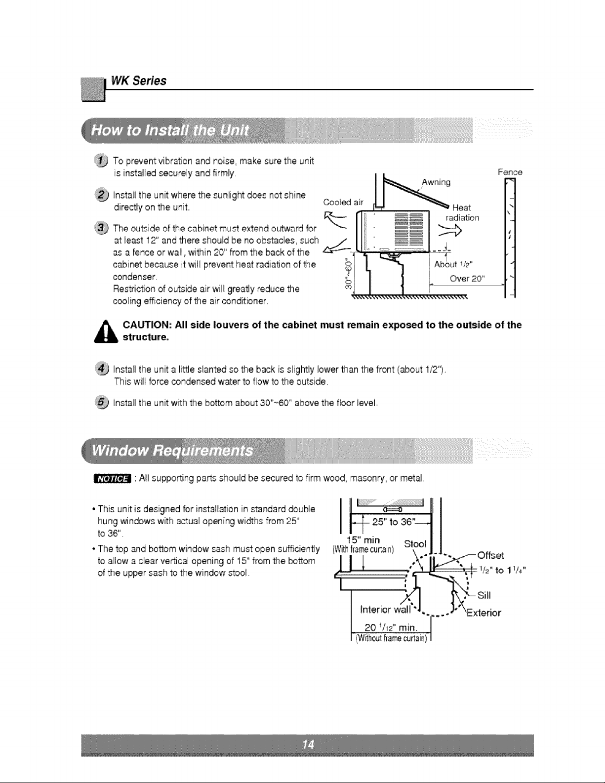
To prevent vibration and noise, make sure the unit
is inst_led securely and firmly,
!nstai_the unit where the sunlight d_s not shine
directly on the unit
The outside of the cabinet must extend outward for
at least 12" and there shouid be no obstacles0 such _/
as a fence or wall, _thin 20 '°from the back of _e
cabinet because it wiil preve_ heat radiation of the
,conde_qser,
Res2ic_on d outside air wil_greatly reduce the
cooling efficiency of the air conditioner,
CA_ION: AIII sWe louvers of the cabinet must remain expo_d to the outside of the,
structure,
install the unit a I_le slanted so the back is slightiy iower than the front (about 1/2°'),,
This will force condensed water to flow to _e outside,
install the unit with the ibo_om a_ut 3,0'"_60°' above the floor ievel
' A!I supporting parts should be secured to firm wood masor_ry,,or metal,
• This unit is designed for ins'tai_ationin standard _uble
hung win_ws 'with a_ual opening wi_hs _'om25"
to 36'",
• The top and bosom 'window sash must open sufficiency
to allow a clear veRical opening of 15" from the bosom
of the upper sash to the window stool°
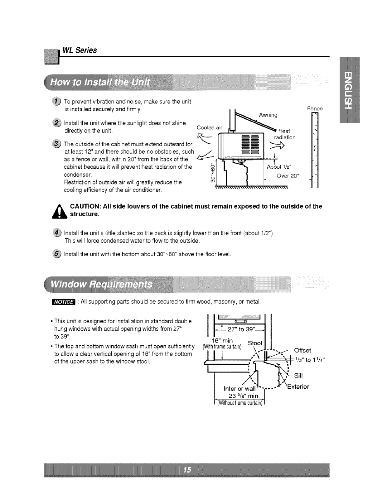
WLSeries
To prevent vibration and noise, make sure the unit
is installed securely and fi_ly
Install the unit where the suniight does not shine
directly on the unit.
_e outside ,ofthe cabinet must extend outward for
at least:12" and there should be no obstacles, such
as a fence or wall, w_hin 20" from #_e back of the
cabinet:because it will prevent hem radiation of the,
_ndenser
Restd_ion of outsi_ air wi}l greatly reduce thie
coo_ingeff:icWencyd _e air oonditioner
1iS'"
Over 20'
Fence
CAUTlON:AIIside louvers: of the caWnetmustremWn ex:posedto the outside of the
structwe.
Instali the unit a ii_e slanted so the back is slightly lower than _e f_ont {a_ut I/2").
This wil_for_, _ondensed water to flow to the outsi_,
Instali the unit wi_ the bottom about: 30'~60 '_above the floor levei.
"Aii supporting pa_s should be secured to firm wood,,masons, or metai.
• This unit is designed for inst_la:ion in standard double
hung windows with actual opening widths from 27'_
to 39",
• The top and bottom window s_h must open sufficiently
to allow a c_earve_cal opening of i6 '_from the bosom
of the up_r sash to the window stool,
'Exterior
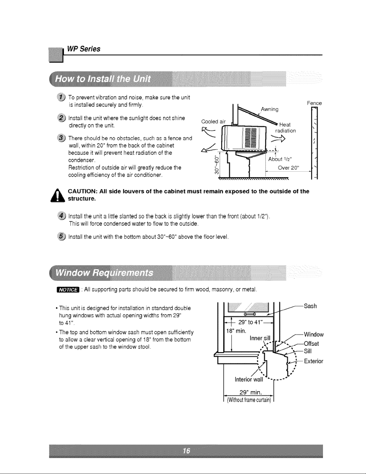
WP Series
To prevent vibration and noise, make sure the unit
is inst_led securely and firmly,
!nstaHthe unit where the sunlight d_s not shine
direc_y on fne unit
There should be no olbst'ac_es0such as a fence and
wall, within 20"' from the back d the cabinet
b_caus,eit will prevent heat radiation of _e
condenser,
Restiction al outside air wili greatly reduce the
cooling efficiency of the air conditioner,
C_led air
Fence
k
radiation
J
1t2'*
Over 20"
CAUTION: All side louvers of the cabinet must remain ex_sed t,othe outside ot the
structure°
Install the unit a li_le s_antedso the back is slightly !ower _an the front: (about i/2'*).
This will force condensed water to flow to _e outside,
Instail the unit w_h the bottom a_ut 30"_60°'above the floor _evei,,
' A!I supporting!parts should be secured to firm wood masonry_,ormetai.
• This unit is designed for ins'tal_ationin standard _uble
hung win_ws 'with a_ual opening wi_hs _'om29''
to 4! '"
• The top and bosom 'window sash must open sufficiency
to allow a clear veRical opening of 18" from the bosom
of the upper sash to the window stool°
|
Exterior
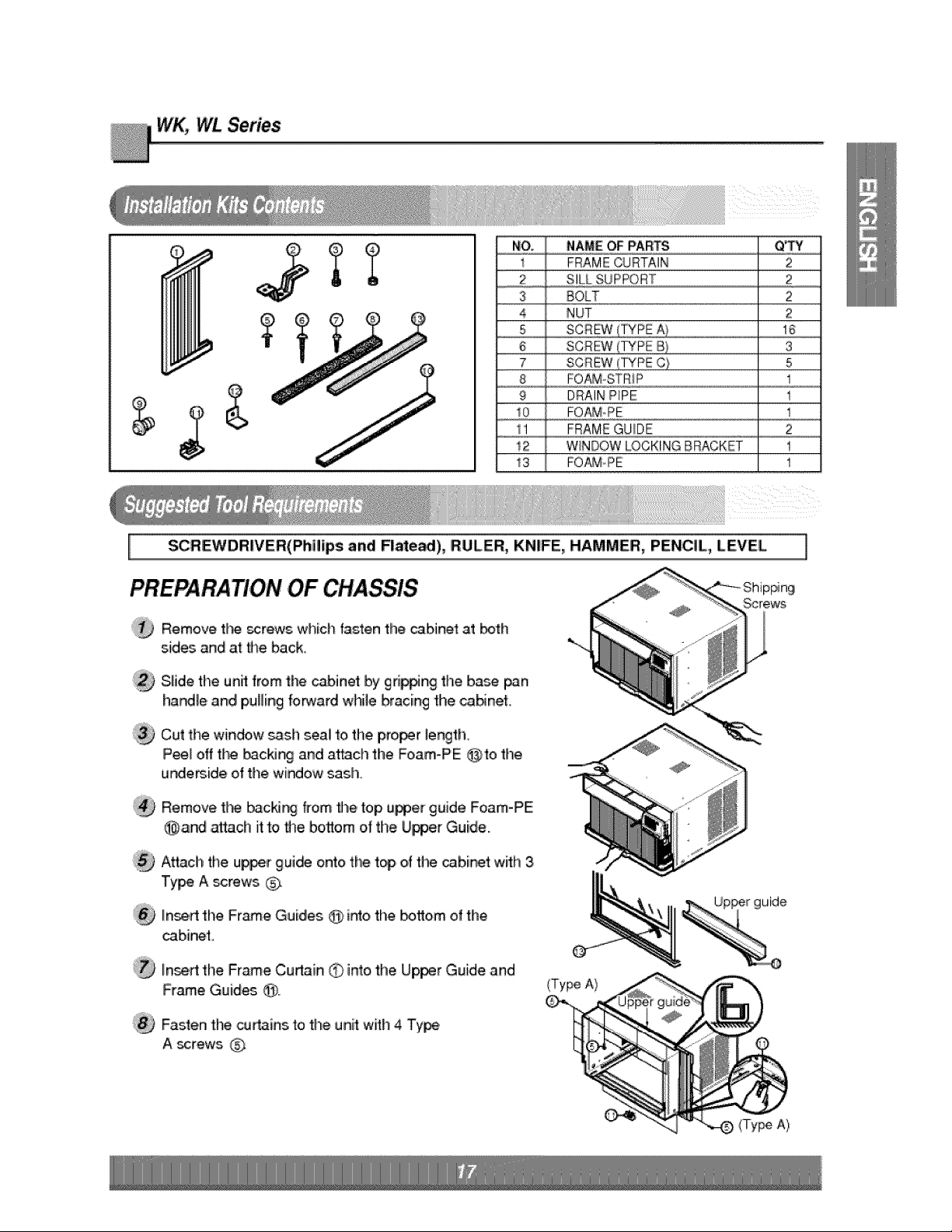
WK_ WL Series
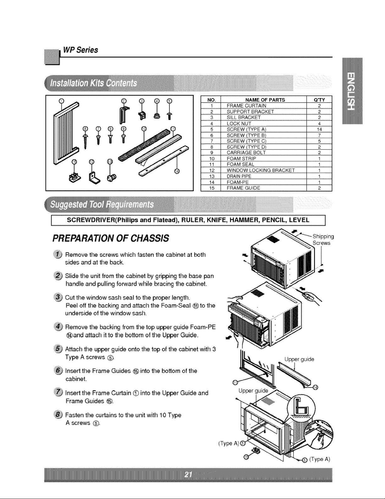
NO,. NAME'OFPARTS QTY
1 FRAMECURTAIN 2
2 SILLSUPPORT 2
3
4
5
6
7
8
9
10
1'1
!2
13
BOLT 2
NUT 2
SCREW o,A_..............................................................16
SCREW(_PE B} S
SCREW_',TYPEC) 5
FOAMoSTR_P 1
DRAINPIPE 1
FO_¢oPE 1
FRAMEGUIDE 2
W_NBOWLOCKINGBRACKET t
FOt_PE 1
SCREWDRIVER(Philips and FI,me,_), RULER, KNIFE, HAMMER, PENCIL,, LEVEL
PREPARATION OF CHASSIS
®
@
®
®
Remove t}-_ _rews which fasten the cabinet at _th
sides ,and at the back,,
Sliide the unff from the cabinet by gd_ng the ba_ _n
ha_le and pulling forward while bracing the caNnet.
Cut the window sastl seal to the proof I,eng'th.
Peel off the _cMng and at_ch the Fo,am-PE @to the
u_eBide of the wi_,ow sash.
Remove t_ _cM_ from fl_e,top u_er guide Foam-PE
@,and _ach it to _e bosom of timeUpper Guide.
Attacl! the u_r gui_ onto the top of the _b,i_t with 3
Type A ,_rews _;x
In_rt the Frame Guides @ i_o the bottom of the
cabinet,
Inert the Frame Cudain 0 into,the Upper Guide and
Frame Guid_ @,
Fasten the cut.ins to the unit: with 4 Ty_
A _rews
]
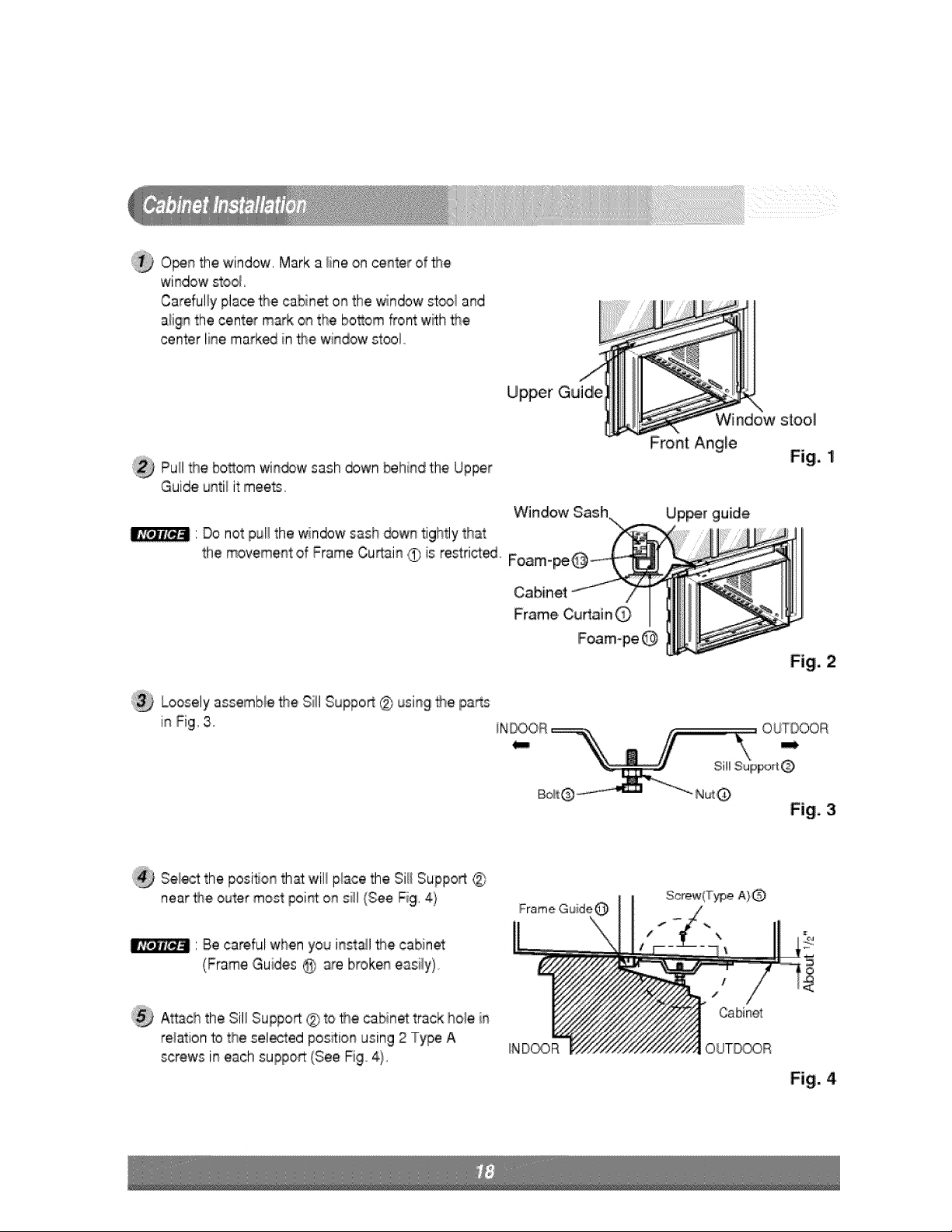
@O_n the window, Mark a line on center of _e
window stool
Carefully place the cabinet on the window sl¢_oland
aiign the center mark on the bo_om front w_h the
center line maA_ in _e window stool,,
Upper Guide
Pu_l_e bo_om win_w sash down behind the Up_,r
Guide until it:meets,_
Window
' Do not pul_the window sash _wn tightly that
the movement of Frame Curtain (9 is restrict_ Foam-
Loosely assemble _lte Sill Suppo_ @ using!_e pa_s
in Fig, 3.
Window stooll
Front Angle
Fig. 1
Up_r guide
OUTDOOR
Sill SUlppo_t @
Fig. 3
'_ Sel,_ the positon th_ will place the Sill Suppo4 @
near t_e outer most point:ion siil (See Fig, 4i
' Be,careful when you install the cabinet
(Frame Guides @ are broken easily)
Frame Guide
Attach:the Sill Suppo_ @ to #'_,ecabinet track ho_ein
r,e_ationto the selected position using 2 Type A
screws in each support:(See Fig, 4),
IND_R
Cabinet
Fig, 4
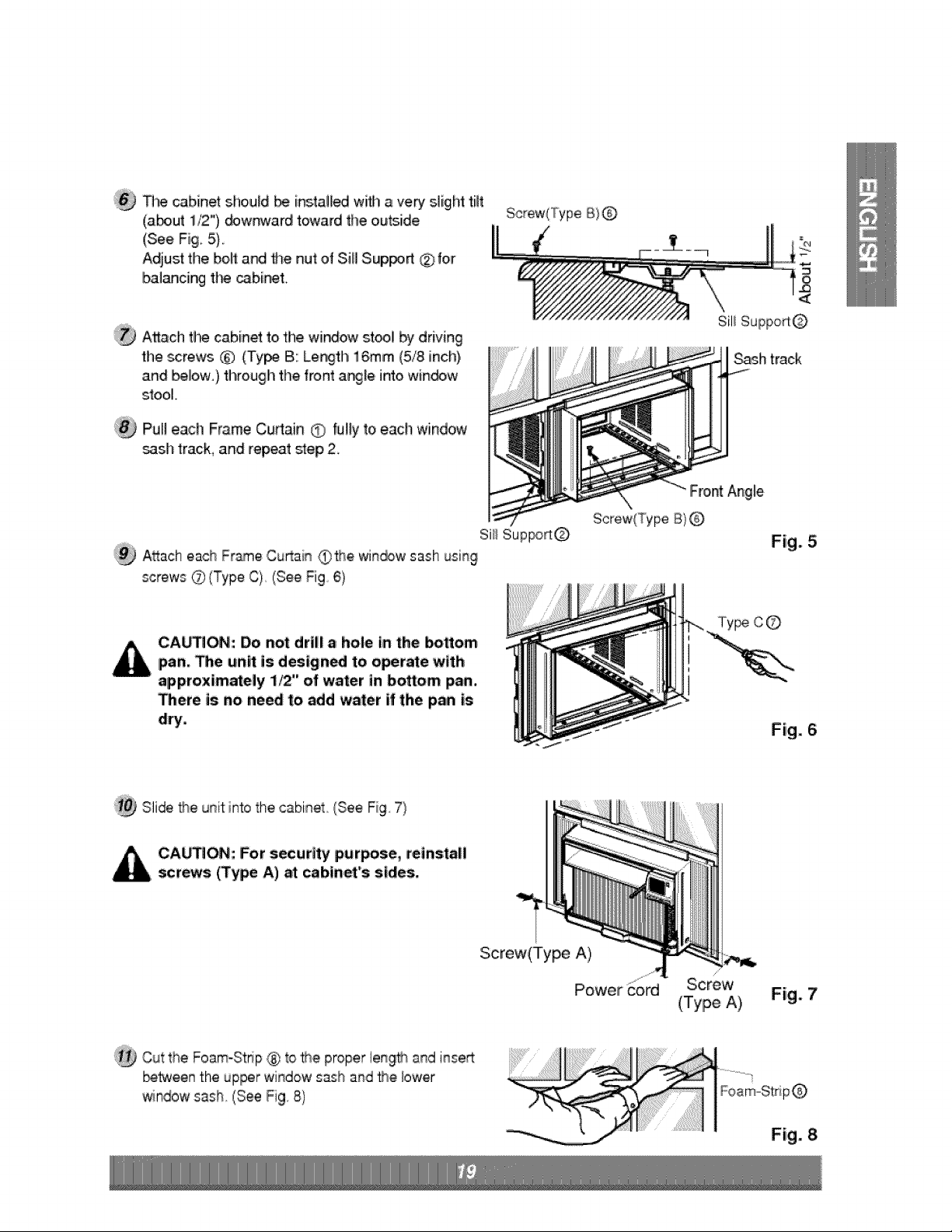
:_ _ cabinet shoiu_dbe i_tall_ wifll, a very slight fit
(a_ut 1/2"),_wr_ard toward the outside
(See Fi9_5).
Adiust the, bolt a_ the nut of Sill Sup_rt _.for
bali_cing t_ c.3bi_t.
Screw(Type B) @
A_.a.ct)the cabinet to the window sty! _ driving
1hie_rews _) (Ty_ B: Leith 16.mm (5/8 inch),
and bellow.} through the front a_le. into win_'w
stool.
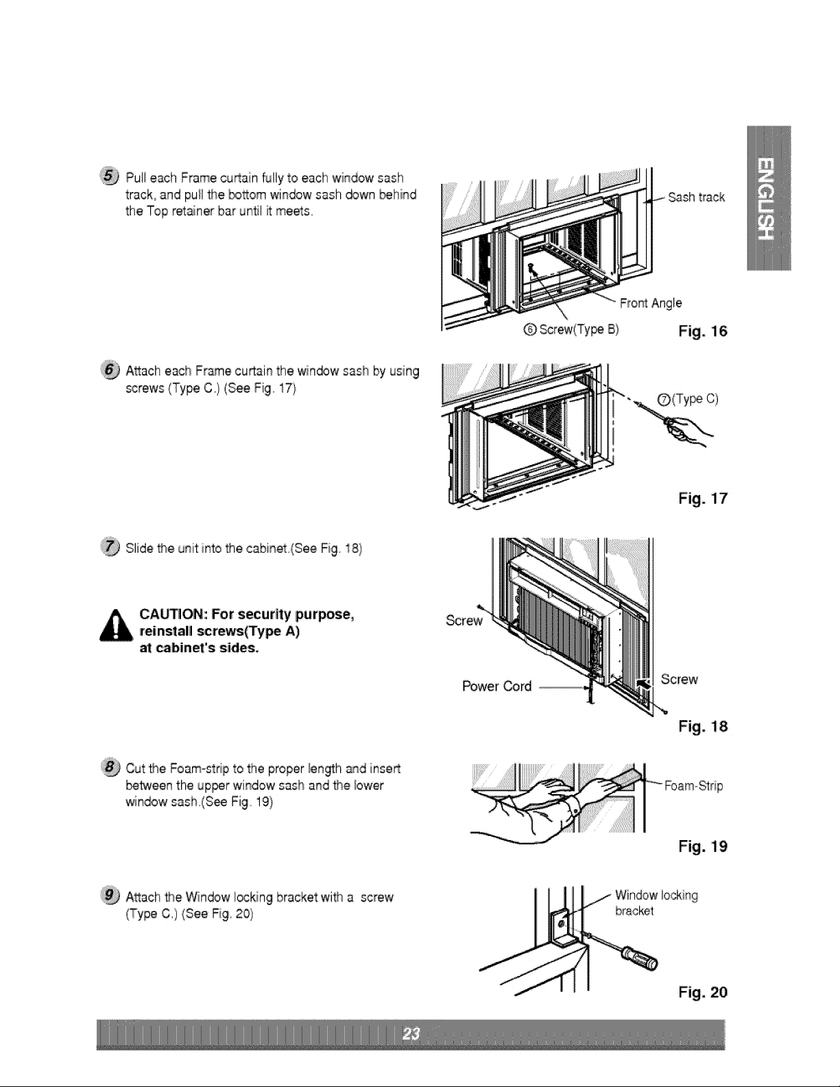
Pu!! each Frame Curtain O hliy to each window
_sh track, and repeat _ep 2.
Froint Ang{e
Screw(Type B}Q
Sil! Suppo_
Sash track
Fig° 5
CA_ON', Do not drill a hole In the _ttom
pan. _e unlt is design_ to oper_e with
approximately 1_" of water in bottom pan.
There is no need toi_d water if the pan is
dry.
Fig. 6
Slide he unit into the cabinet. ,(SeeFig. 7)
CA_ON: For security purpose, reinstall
screws (Type A) at cahiin,et"ssides.
Screw(Type A}
Power
(Type A)
Fig. 7
Cut the Foam-St:alp® to _e proper length and inse_
be_een the upper window sash and _e bwer
window sash. (See Fig .8)
Fig. 8
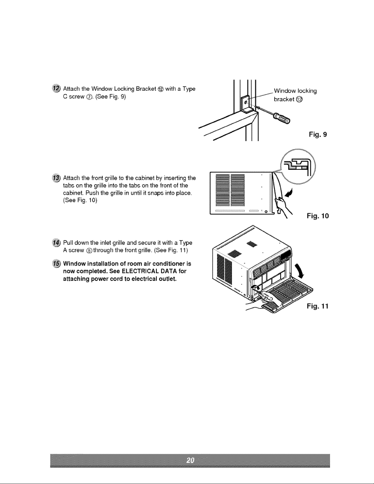
':_ A_ach the Widow L_king Bracket @ w_:h a Ty_
C _re'w Q (be Fig 9)
Win_w Io,ckir_g
bracket @
Fig. 9
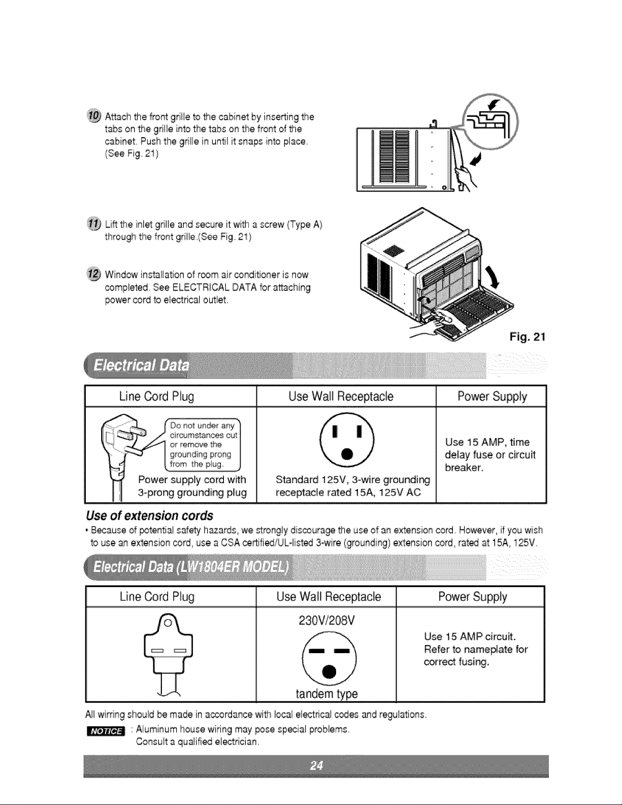
A_ach the, fro_ grille to the cabinet by insedingtile
ta_ on the grille into the ta_ on the front of the
canner. Push the grille in until it snaps i_o piace
(See Fig i0),
O
Fig. 10
Pull down the inllet grille _d secure it witl_ a T_e
A screw 6.)thro,ugh the front gdllle, (See Fig, 11)
Window in_al_ation ,of room air conditioner is
now completed. See ELECTRICAL DATA for
a_aching power cord to el,_trical out_et,
Fig. 11
WP Series
NAME OF PARTS Q'TY
i FRAME CURTAIN 2
2 suPPoR"rBR.ACKE[ 2
3 S_LL BRACKET 2
4 LOCK NUT 4
SCREW (TYPF A} 14
SCREW (TYPE B_ 7
..... _CRE 5
5
6
7
8
9
10
11
12
13
14
15
_REW (TYPE D) 2
CARRIAGE BOLT 2
FOAM S"FRiP .......................................1......
FOAM SEAL 1
WINDOW LOCKING BRACKET 1
DRNN PiPE ..........................! ......................
FOAM-PE 1
FRAME GUIDE 2
1111¸
I SCREWDRWER(Phiiips and Flatead), RULER, KNIFE,, HAMMER, PENCIL, LEVEL ]
PREPARATION OF CHASSIS
Remove t}-_ _rews which fasten the cabinet at _th
sides ,and at the back..
@ Sliide the unff from the cabinet by gd_ng the ba_ _n
ha_le and pulling foeward whiJe bracing the cannel.
:_ Cut the window sastl seal to the pro_r length.
Peel off the _cNng and at_ch the Foam-Seal @to the
u_e_ide of the wi_,ow sash.
Remove t_ _c_ from fl_e,top u_er guide Foam-PE
@,and _ach it to _e bosom of tile Upper Guide,
@ Attac!! the u_r gui@ onto the top, of the _bJi_t with 3
Type A ._rews _]x
Inert the Frame Guides @ i_o the bottom of the
cabinet,
Inert the Frame Cur'_in @ into,the Upper Guide and
Frame Guid_ _,
Fasten the cut,ins to the unit with 10 Type,
A _rews 6_.
_O_n thewindow.Marka Be onthecenterof_e
windowstoolbelb,t_eenthesi_ windowstop
moldings.
Looselyattachthesillbrackettothesuppo_
bracketusing _e carnage _:_itand the I_k nut.
A_aclhthe si_lbracket to the window sill using _e
screws (Type B)..
Carefuliy place the cabinet on the window st_i
and a!ign the center mark on _e bottom _ont with
the center line maAed window stool..
Using the M-screw and the bck nut, a_ach the
suppo_ bracket to _e cabinet track hob. Usethe first
track hole after the sill bracket on the outer _g,e of
the window sill. Tighten t_e carria_ bo_ and the bck
nut. Be _ure the cabinet slants outward
C_inet
Trackhale
si_
(Type B}
Sillbracket
Fig,. 13
CAUTION; Oionot dlril| a holle in the bottom
_n. The unit is designed to o_rate with
ap,proximate|y 1/2" of water in bottom pan,
Guide
Pu_I_e bosom win®w sash down behind the Top
retainer bar u_il they meier
:1. Do not pull _-_ewin®w sash down so tighfly
_at the movement d Frame cu_ain is
rest_cted.
Attach the cabinet t:o_e win_w stool by
driving the screws (Type B} _rough the
cabinet i_o win®w stool.
2. The cabinet shouid be installed wi_ a very
slight tilt @wnward toward _e outside,
Wir_dew sash
Ca,big'let
Framecu4ain
PuI_eachFramecu_ainfullytoeachwindowsash
track,andpu_l_e bosomwindowsashdownbehind
theTopret_nerbarun#lit meets,
track
A_acheachFramecu_ainthe_ndowsashbyusing
screws(TypeC,}(SeeFig,17)
Fto_Angle
Q Screw(Ty_B) Fig. 16
Fig. 17
Slide _e unit into the cabinet(See Fig, i8 /
CA_ON: For security purpose,
reinstall _r_s(Type A)
cabinet's sides.
Power Cord
Screw
Cut _e Foam-strip to the proper len_h _d insert
_tween the, upper window sash and the bwier
windowsash,(S_ Fig, 19)
Fig. 18
Fig. 19
A_ach the Windowlocking bracket with a screw
(Type C,) (See Fig, 20}
i
111 WiRdow locking
bta,cket
Fig. 20
:_ Attach the front 9til e to the cabinet by inse_ing the
t_s on '_e grille into thietabs on the front of the
cabinet Push the 9rille in un_l it snaps into place
(See Fig. 21}
:1_ Lfff _e inlet 9rifle and secure it with a screw (Type A)
through the front gdl:e.(See Fig. 21 )
Window instaHa_onof room air _ndi_oner is now
completed See ELECTRICAL DATA for attaching
power cord to ei_rical out_et.
Line _,rd Plug Use Wall RecepCacle Power Supply
Use 15 AMP_ time
delay fuse or circuit
breaker°
Standard 125V, 3°wire grounding!
receptacle rated 15A_ 125V AC
Use of extension cords
,'B_ause of potential safety h_ards, we _rongly discourage the use of an extension cord_ However, if you wish
_ouse an extension cord, use a CSA _rtifiediUL4ist_ 3owire(grounding} extension co#d,r_t_ at 15A_125V
Line Cord Plug Power SupplyUse Wall Receptacle
230V!208V
tandem ty_
Use 15 AMP circuit.
Refer' 'to,name#ate for
correct fusi_,
_1 wimn9 should be made in a_ordance wi#_local el_tnc_ codes and regulations,
Al_Jminumhouse 'wiring may pose special proNems.
Consuff a qu_ifi_ ele_rician.
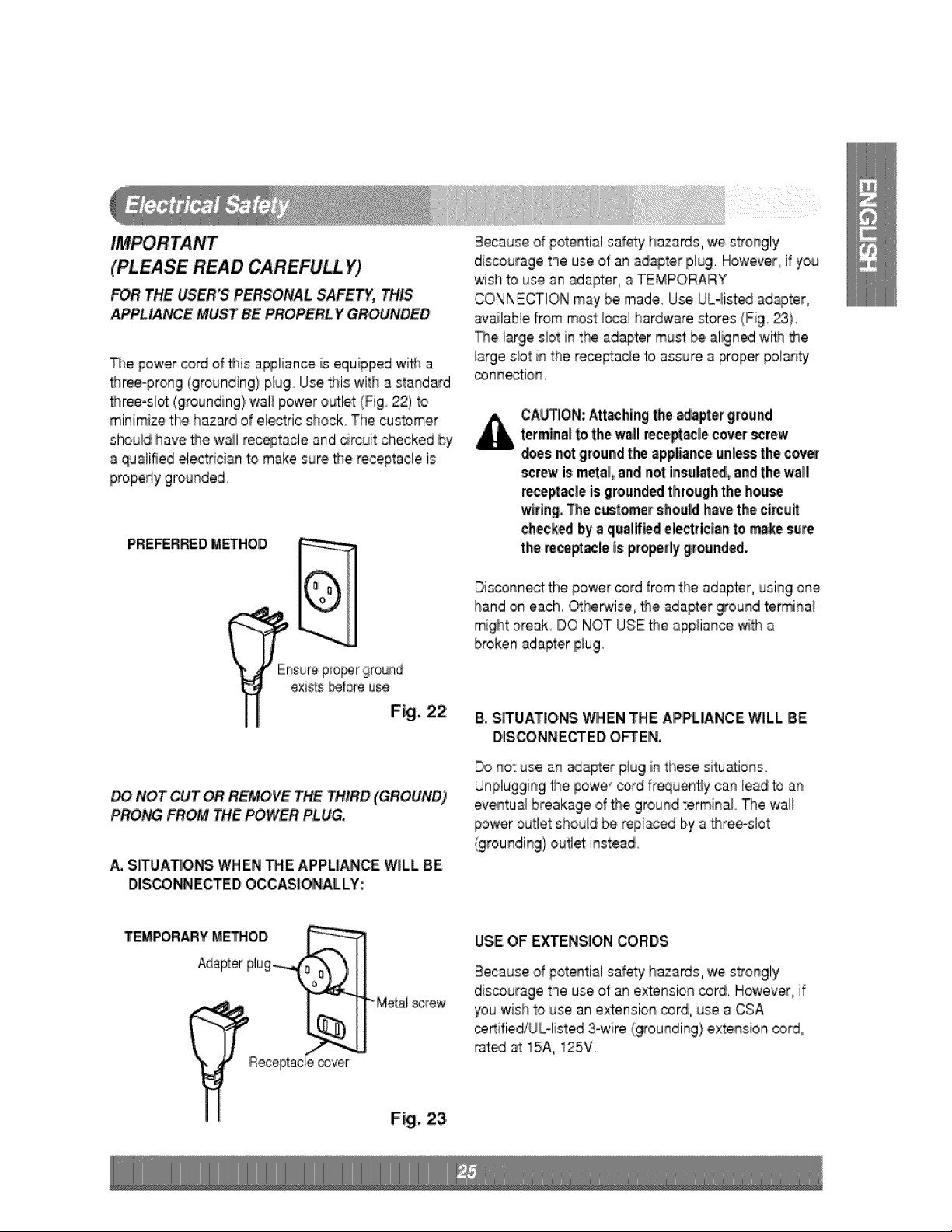
(PLEASE READ CAREFULL Y)
FOR'THE USER'S PERSONAL SAFETY, THIS
APPLIANCE MUST BE PROPERL iyGROUNDED
The power cordofthis appliance is equipped wit_ a
_ree=prong (grorJnding) p_ug..Use _is with a standard
bhree-slot(grounding) wall power o_let (Fig 22) to
minimize the hazard of electric shock. The customer
should have _e wail receptacle and circuit checked by
a qualified electrician to make sure _e receptacle is
propedy grounded.
PREFERRED M_HOD
Ensurep#o_r ground
existsbeforeuse
Fig. 22
NOT CUT OR REMOVE THE THIRD (GROUND)
PRONG FROM THE POWER PLUG,
A. S_UA_O_ WHEN THE APPLIANCE WILL BE
DISCONNECTED OCCASIONALLY:
Because d potential safety h_ards, we strongly
discourage the use of an adapter plug, However, if you
wish to use an adapter, a TEMPORARY
CONNECTION may be made,, Use,UL-list_ adapter,
available from most i_al hardware stores (Fig. 23},
The iarge slot in the adapter mu_ be aligned with the
iarg!es!ot in the receptac!e to assure a proper pola_ty
_nnection,
CAb%ION:,Attaching the _apter ground
terminalf,othe wall rece_le cover screw
dioesnot groundthe appliance unless the cover
scr_ is metal,andlnot insulat_i, and the wall
recept_le is groundedthroughthe house
wtdngoThe castomet shoald havethe c#cait
checkedby a qualif_d electricianto make sere
the te_ptacle is properlygrounded,
Disconne_ the power cord from the adapter, using one
hand on each. _he_ise, _e adapter ground terminal
might break IDONOT USE _e appliance 'w_tha
broken adapter piug
B. S_UATIONS, WHEN THE APPLIANCE 'WILL BE
DISCONNECTED OFTEN.
not:use an adapter plug in these situations..
Unplugging the power oord fr_uenty can lead to an
eventu_ breakage of the ground termina_ The wal_
power outlet should be replaced by a fl_ree-dot
(grounding} outlet instead°
TEMPORARY M_OD
Riecep_acle_ver
screw
Fig. 23
USE OF E_ENSION CORDS
Because d potential safety h_ards, we strongly
discourage the use of an extension cord. However, if
you wish to use an extension cord, use a CSA
_rtifiediUblisted 3owi_ (grounding} extension cord
rat_ at 15A, 125V
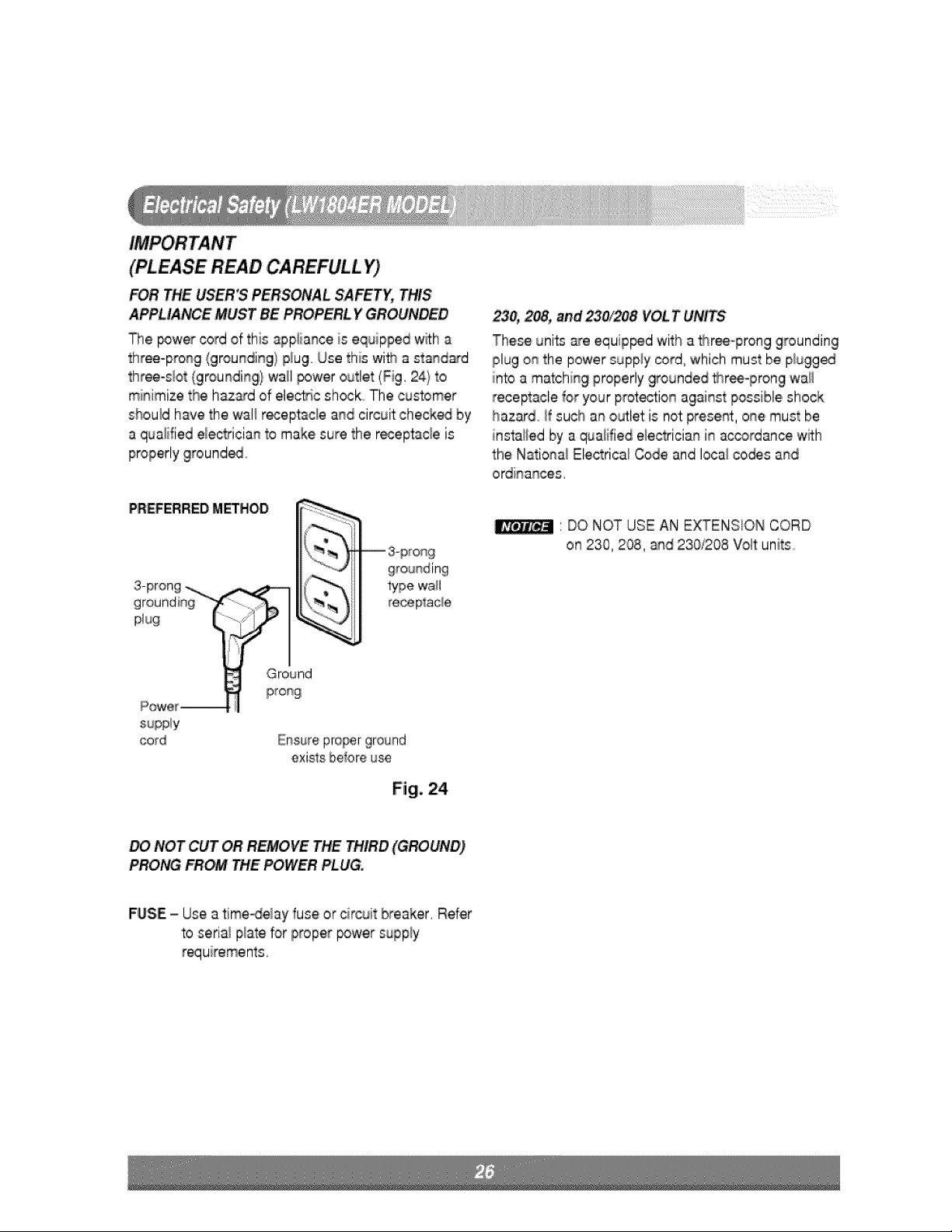
(PLEASE READ CAREFULL Y)
FOR THE USER'S PERSONAL SAFETY,,THIS
APPLIANCE MUST BE YGROUNDED
The _wer cord of this appiiance,is equipped wffh a
three-prong {groulnding}plug. Use this with a standard
three-sl,ot(grounding} wall power outlet (Fig, 24} to
minimize the hazard of ele_ic shock. The customer
should have the wa]_receptacle and circuit check_ by
a qualified e_ectricianto make,sure the r_eptacle is
properly 9round_o
PREFERREDMETHOD
teceplac_e
23& 2e8,,and VOLT UNITS
These units a_reequip_d with a _ree-prong grounding
plug on the power supply _rd,, which must be pbgged
into a matching properly grounded tthr_-prong wall
receptacle for your prot_ion agait%t possible,shock
hazard _fsuch an outlet is not present, one must be
instai_edby a quaiified eieGrician in ac_rdance with
the National Electrical Code and Ioca_co_s and
ordinances,
:lDO NOT USE AN EXTENSION CORD
on 230,208, and 230/208 Volt units
supply
cord
Ground
prong
Ensure pro_r ground
existsbelore use
Fig. 24
NOT CUT OR REMOVE THE THIRD (GROUND)
PRO_ FROM R"tEPOWER PLUG.
FUSE,= Use atime_e_ay fuse or circuit blreaker, Refer
to serial pilatefor proper _wer supply
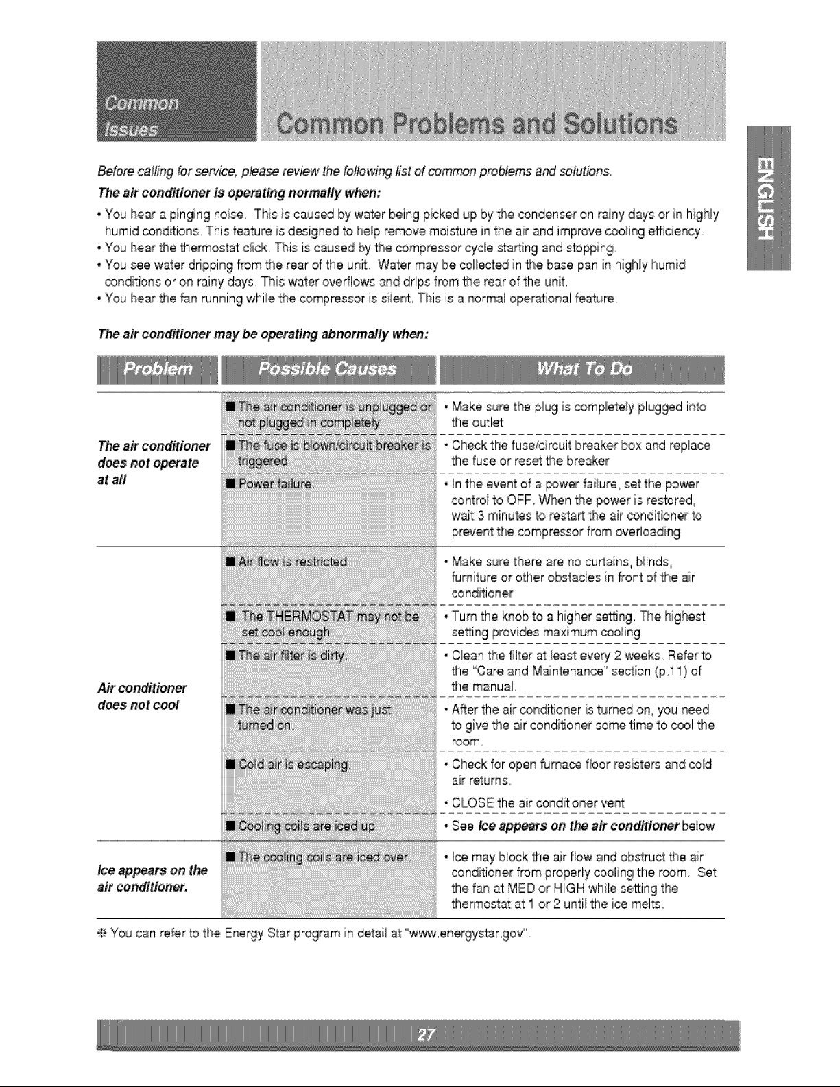
Before calling for service, p_ase review me, following list of common probtems aM solutions.
T_ air conditioner is operating normally when:
• You hear a pinging noise This;is caused by water bein9 picked up by _e condenser on rainy days or in highly
humid condffions This feature is designed to he_p remove moisture in the air and improve _o_ing efficiency
• You he__the thermostat c#ck, This is caused by _e compressor cycle stain 9 and stoppin9
• You see water dripping from the rear of the unit 'Water may be _llec-t_ in the base pan in high!y humid
_nditions or on rainy days. This water overflows and drips from the rear of the unit.
, You hear the fan running while _e compressor is silent, This is a normal operational feature.
air conditioner may be operating abnormally when:
air conditioner
does not opiate
at all
,,Make sure the p_ugis _mp_ete/y plugged into
the outlet
• Check the fuse/circuit breaker box and replace
the fuse or reset _e breaker
,,_nthe event of a _wer failure,, set the power
contro} to OFF, When _e power is restored,
wait 3 minutes to res:ta__e air _nditioner to
prevent the compressor from overloading
4+You can refer to the Energy Star program in detail at ww_,ene gystar@ov ,,
iiiii!iiiiiiiiiii1i;%111111;:iiiiiiiiiiiiiiiiiii:i;iii iiiiiiiii::iiiiii....................iiii_i_i_i_i_i_i_i_i_i_i_i_iiiiiiiiiiiiiiiiiiiiii_
Make _u e t ere are no cu_an_, Nlnd_
fumitu_ or other obstacles in front of the air
¢ond t onor
se_ n p_ov_ maximum _
g g
,,Cle_n _e filter at _easteve_ 2 weeks° Refer to
the Care and Maintenance' section (p.ll) of
Airconditionerdoesnot, cool a_le:a, ' theA_ermanual,theair condiSoner i_-turned on you need
to ve _e a r condit oner some t me to coo _e
room,
.,Check for open furnace floor resisters and co_d
air returns.
* CLOSE the air condffioner vent
.,See a pea,so. oon , o ,below
Ice may block the a,r flow and ob_truc[__e air
Ice appears on t_ conditioner from,pr,operly coolin9 'the r_m, Set
air conditioner, the fan letMED or HIGH while setting the
thermostat at 1 or 2 until the ice melts,

