G
ROOM AIR CONDITIONER
website http://www.lgapplian _
OWNER'S MANUAL
Please read the operating instructions and safety precautions carefully
and thoroughly before installing and operating your room air conditioner.
DEVENTANA
,o
FOR YOUR RECORDS
Write the model and serial numbers here:
Model #
Serial #
You can find them on a label on the side of each unit.
Dealer's Name
Date Purchased
[] Staple your receipt to this page in the event you need it
to prove date of purchase or for warranty issues.
READ THIS MANUAL
inside you will find many helpful hints on how to use and
maintain your air conditioner properly. Just a little preventive
care on your part can save you a great deal of time and
money over the life of your air conditioner.
You'll find many answers to common problems in the chart
of troubleshooting tips. if you review our chart of
Troubleshooting Tips first, you may not need to call for
service at all
PRECAUTION
®Contact the authorized service technician for repair
or maintenance of this unit.
, Contact the installer for installation of this unit.
=The air conditioner is not intended for use by young
children or invalids without supervision.
,Young children should be supervised to ensure that
they do not play with the sir conditioner.
• When the power cord is to be replaced, replacement
work shaft be performed by authorized personnel only
using only genuine replacement parts.
, Instaflation work must be performed in accordance
with the National Electric Code by qualified and
authorized personnel only.
2 Room Air Conditioner
SafetyPrecautions
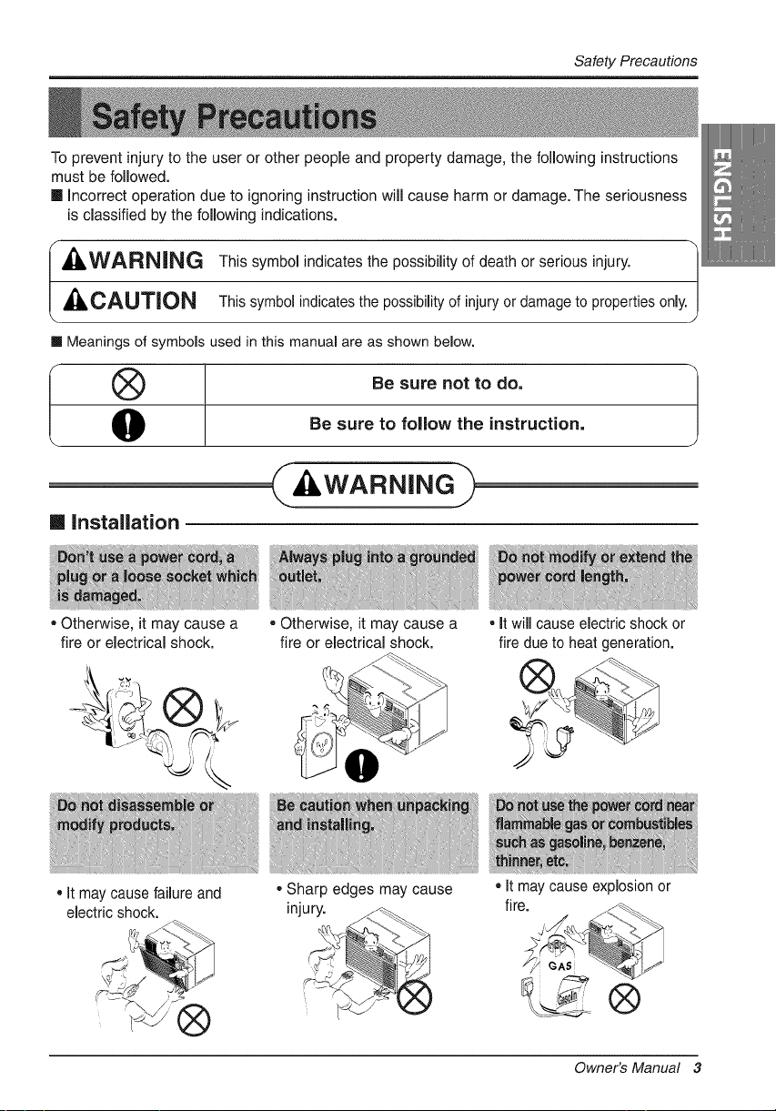
To prevent injury to the user or other people and property damage, the following instructions
must be followed.
m Incorrect operation due to ignoring instruction will cause harm or damage. The seriousness
is classified by the following indications.
,WARNING This symbol indicates the possibility of death or serious injury.
CAUTION This symbol indicates the possibility of injury or damageto properties only.
m Meanings of symbols used inthis manual are as shown below.
(_ Be sure not to do,
O Be sure to follow the instruction,
WARNING>
[] installation
• Otherwise, it may cause a
fire or electrical shock.
• Otherwise, it may cause a
fire or electrical shock.
• it will cause electric shock or
fire due to heat generation.
It may cause failure and
electric shock.
®
, Sharp edges may cause
injury. _._._
, It may cause explosion or
fire.
®
Owner's Manual 3
Safety Precautions
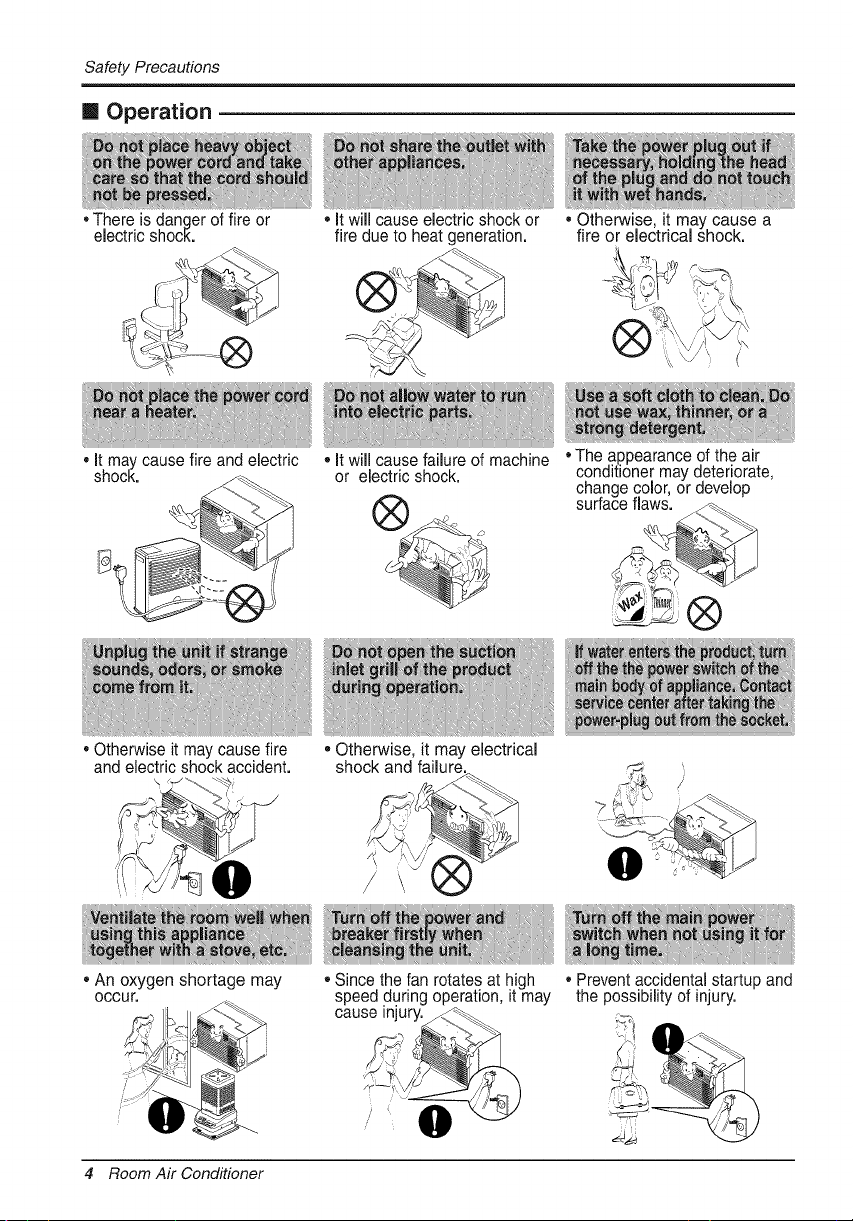
[] Operation
• There is danger of fire or
electric shock.
• It will cause electric shock or
fire due to heat generation.
%
• Otherwise, it may cause a
fire or electrical shock.
• It may cause fire and electric
shock.
• It will cause failure of machine
or electric shock.
,,The appearance of the air
conditioner may deteriorate,
change color, or develop
surface flaws.
®
• Otherwise it may cause fire
and electric shock accident.
• An oxygen shortage may
OCCUr,
, Otherwise, it may electrical
shock and failure.
• Since the fan rotates at high
speed during operation, it may
cause injury__
• Prevent accidental startup and
the possibility of injury.
4 Room Air Conditioner
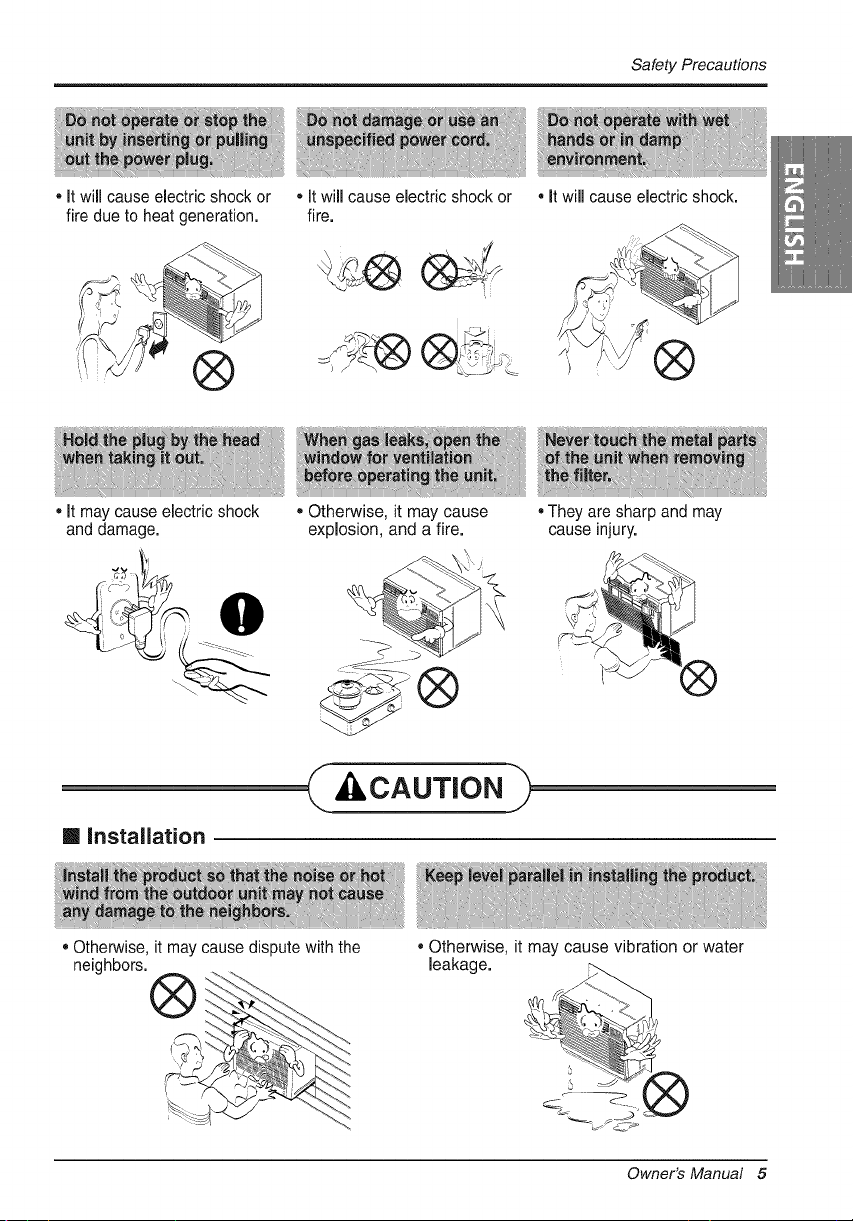
• It will cause electric shock or
fire due to heat generation.
* It will cause electric shock or
fire.
Safety Precautions
• It will cause electric shock.
®
It may cause electric shock
and damage.
• Otherwise, it may cause
explosion, and a fire.
[] installation
._S _ .........
®
C, CAUTION
• Otherwise, it may cause dispute with the
neighbors.
• They are sharp and may
cause injury.
, Otherwise, it may cause vibration or water
leakage.
Owner's Manual 5
SafetyPrecautions
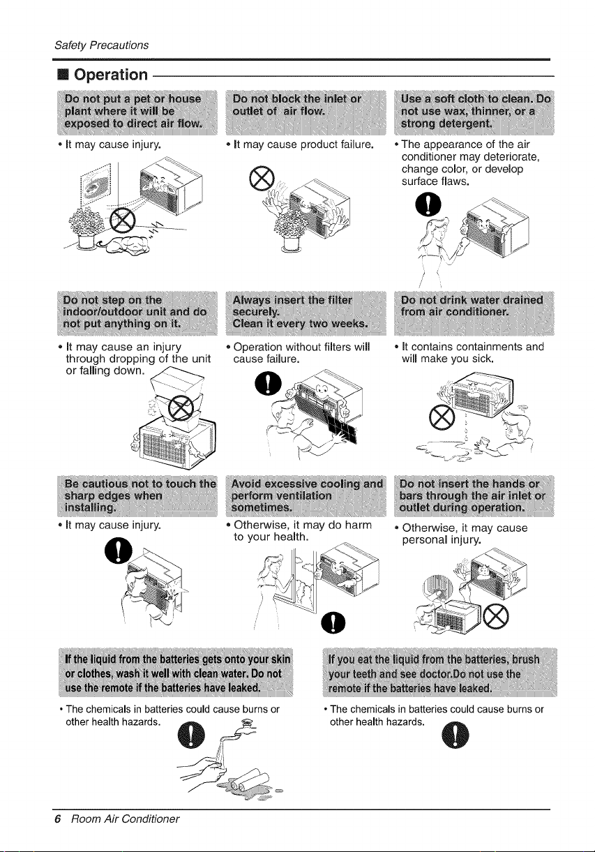
m Operation
• It may cause injury. o It may cause product failure. The appearance of the air
conditioner may deteriorate,
change color, or develop
surface flaws.
0
/
o It may cause an injury
through dropping of the unit
or falling down.
It may cause injury.
o Operation without filters will
cause failure.
= Otherwise, it may do harm
to your health.
• The chemicals in batteries could cause burns or
other health hazards.
• It contains containments and
will make you sick.
®Otherwise, it may cause
personal injury.
• The chemicals in batteries could cause burns or
other health hazards.
6 Room Air Conditioner
PriortoOperation
1. Contact an installation specialist for installation.
2. Plug in the power plug properly.
3. Use a dedicated circuit.
4. Do not use an extension cord.
5. Do not start/stop operation by plugging/unplugging the power cord.
6. If the cord/plug is damaged, replace it with only an authorized replacement
part.
1. Being exposed to direct airflow for an extended period of time could be
hazardous to your health. Do not expose occupants, pets, or plants to direct
airflow for extended periods of time.
2. Due to the possibility of oxygen deficiency, ventilate the room when used
together with stoves or other heating devices.
3. Do not use this air conditioner for non-specified special purposes (e.g.
preserving precision devices, food, pets, plants, and art objects). Such usage
could damage the items.
1. Do not touch the metal parts of the unit when removing the filter. Injuries can
occur when handling sharp metal edges.
2. Do not use water to clean inside the air conditioner. Exposure to water can
destroy the insulation, leading to possible electric shock.
3. When cleaning the unit, first make sure that the power and breaker are turned
off. The fan rotates at a very high speed during operation. There is a
possibility of injury if the unit's power is accidentally triggered on while
cleaning inner parts of the unit.
For repair and maintenance, contact your authorized service dealer.
Owner's Manual 7
Introduction
&
This symbol alerts you to the risk of electric shock,
This symbol alerts you to hazards that could cause harm to
the air conditioner,
This symbol indicates special notes.
_WARNING
This appliance should be installed in accordance with the National Electric Code.
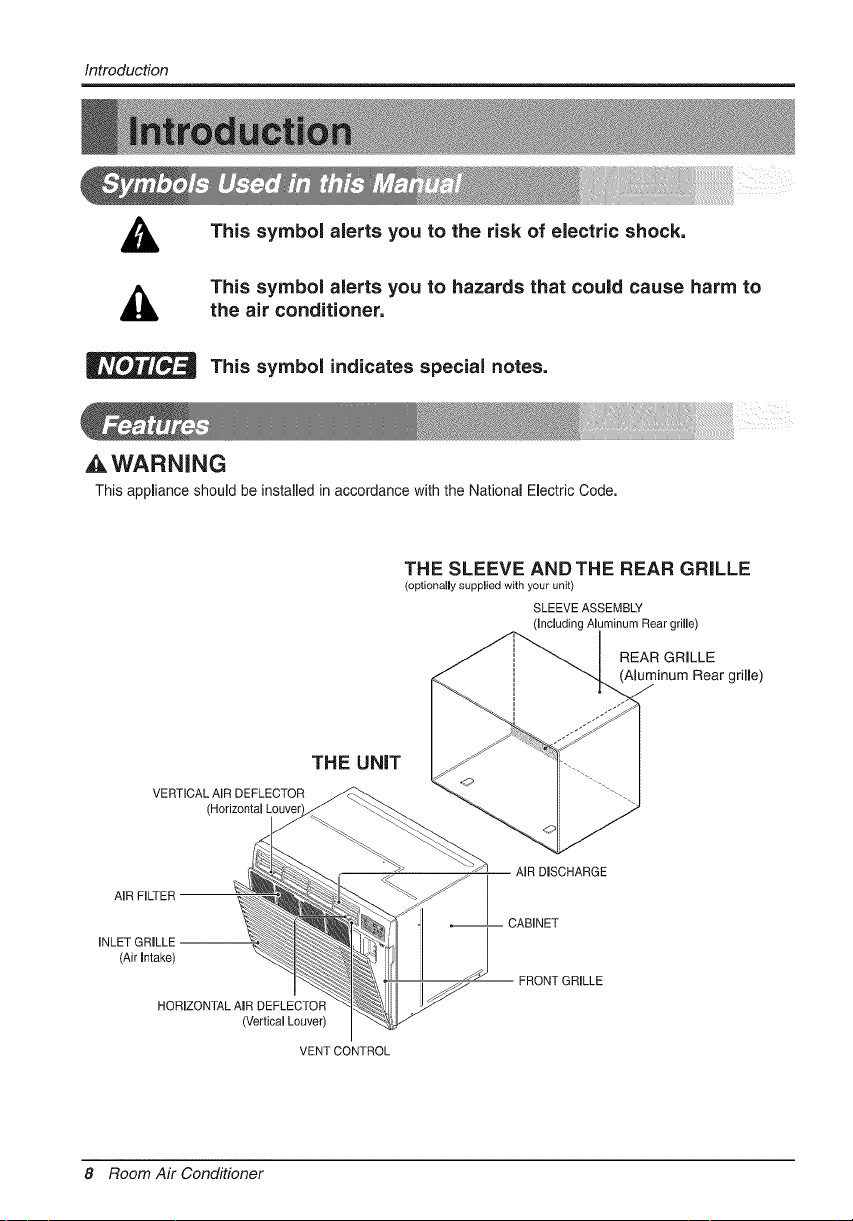
THE SLEEVE ANDTHE REAR GRILLE
(optionally supplied with your unit)
SLEEVE ASSEMBLY
(Including Aluminum Rear grille)
REAR GRILLE
(Aluminum Rear grille)
THE UNiT
VERTICAL AIR DEFLECTOR
(I
AIR FILTER
INLET GRILLE --
(Air Intake)
HORIZONTAL AIR DEFLECTOR
(Vertical Louver)
VENT CONTROL
AIR DISCHARGE
CABINET
FRONT GRILLE
8 Room Air Conditioner
ElectricalSafety
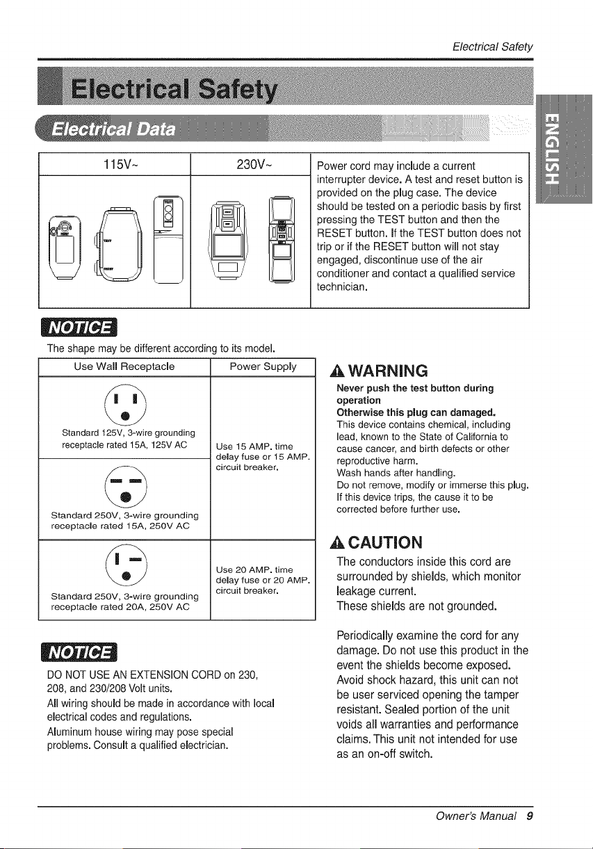
115V- 230V~
Power cord may include a current
interrupter device. A test and reset button is
provided on the plug case. The device
should be tested on a periodic basis by first
pressing the TEST button and then the
RESET button. If the TEST button does not
trip or if the RESET button will not stay
engaged, discontinue use of the air
conditioner and contact a qualified service
technician.
The shape may be different accordin( to its model.
Use Wall Receptacle Power Supply
©
Standard t 25V, 3-wire grounding
receptaclerated 15A,125VAC Use 15 AMP.time
delay fuse or 15 AMP.
circuit breaker.
Standard 250V, 3-wire grounding
receptacle rated t 5A, 250V AC
Use 20 AMP. time
delay fuse or 20 AMP.
circuit breaker.
Standard 250V, 3-wire grounding
receptacle rated 2OA, 250V AC
DO NOT USE AN EXTENSION CORD on 230,
208, and 230/208 Volt units.
All wiring should be made in accordance with local
electrical codes and regulations.
Aluminum house wiring may pose special
problems. Consult a qualified electrician.
,&WARNING
Never push the test button during
operation
Otherwise this plug can damaged.
This device contains chemical, including
lead, known to the State of California to
cause cancer, and birth defects or other
reproductive harm.
Wash hands after handhg.
Do not remove, modify or immerse this plug.
If this devicetrips, the cause it to be
corrected before further use.
,& CAUTION
The conductors inside this cord are
surrounded by shields, which monitor
leakage current.
These shields are not grounded.
Periodically examine the cord for any
damage. Do not use this product in the
event the shields become exposed.
Avoid shock hazard, this unit can not
be user serviced opening the tamper
resistant. Sealed portion of the unit
voids all warranties and performance
claims. This unit not intended for use
as an on-off switch.
Owner's Manual 9
ElectricalSafety
IMPORTANT
(PLEASE READ CAREFULLY)
FOR THE USER'S PERSONAL SAFETY,THiS
APPLIANCE MUST BE PROPERLY GROUNDED
The power cord of this appliance is equipped with a
three-prong (grounding) plug. Use this with a standard
three-slot (grounding) wall power outlet to minimize the
hazard of electric shock. The customer should have the
wall receptacle and circuit checked by a qualified
electrician to make sure the receptacle is properly
grounded.
DO NOT CUT OR REMOVE THE THIRD (GROUND)
PRONG FROM THE POWER PLUG.
A. SITUATIONS WHEN THE APPLIANCE WiLL BE
DISCONNECTED OCCASIONALLY:
Because of potential safety hazards, we strongly
discourage the use of an adapter plug. However, if you
wish to use an adapter, a TEMPORARY CONNECTION
may be made. Use ULqisted adapter, available from
most local hardware stores.
The large slot in the adapter must be aligned with the
large slot in the receptacle to assure a proper polarity
connection.
CAUTION
: Attaching the adapter ground terminal to the wall
receptacle cover screw does not ground the appliance
unless the cover screw is metal, and not insulated, and
the wall receptacle is grounded through the house
wiring, The customer should have the circuit checked
by a qualified electrician to make sure the receptacle
is properly grounded.
Disconnect the power cord from the adapter, using one
hand on each. Otherwise, the adapter ground terminal
might break. DO NOT USE the appliance with a broken
adapter plug.
B. SiTUATiONS WHEN THE APPLIANCE WiLL BE
DISCONNECTED OFTEN.
Do not use an adapter plug in these situations.
Unplugging the power cord frequently can lead to an
eventual breakage of the ground terminal. The wall
power outlet should be replaced by a three-slot
(grounding) outlet instead.
USE OF EXTENSION CORDS
Because of potential safety hazards, we strongly
discourage the use of an extension cord. However, if
you wish to use an extension cord, use a CSA
certified/UL-listed 3-wire (grounding) extension cord,
rated at 20A, 250V.
10 Room Air Conditioner
Installation
Remove packing sheet from the back of the sleeve, and
packing corner and blue tape from the air conditioner.
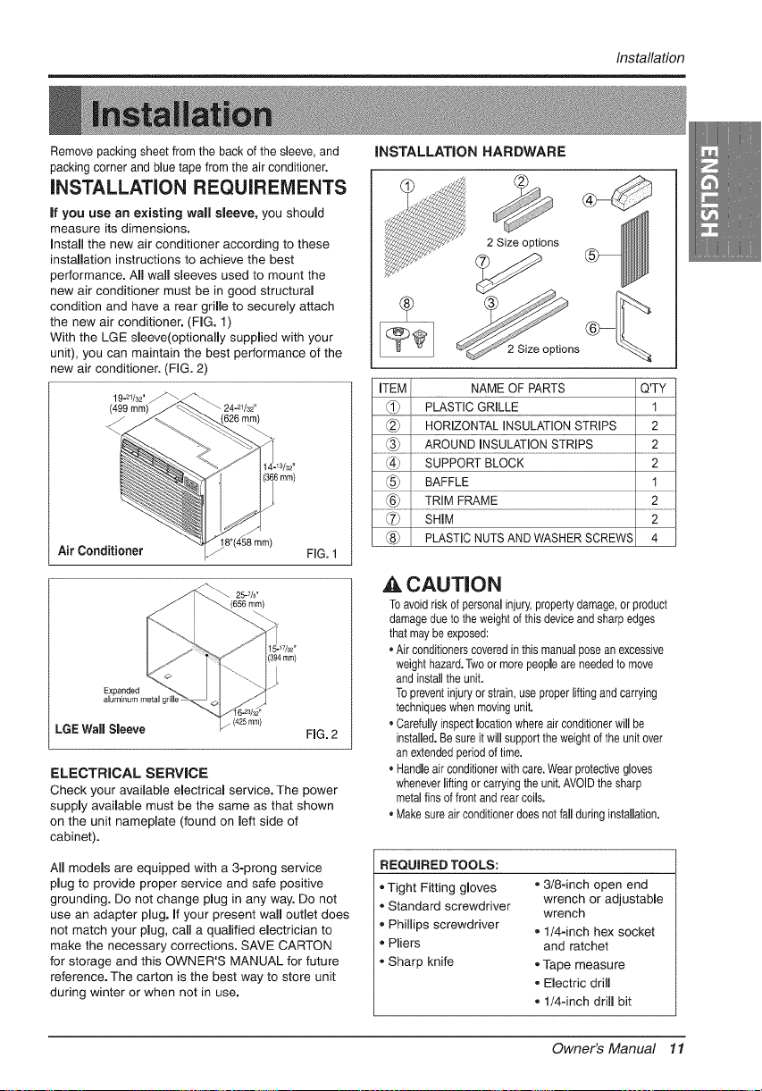
iNSTALLATiON REQUIREMENTS
If you use an existing wall sleeve, you should
measure its dimensions.
Install the new air conditioner according to these
installation instructions to achieve the best
performance. All waft sleeves used to mount the
new air conditioner must be in good structural
condition and have a rear grifle to securely attach
the new air conditioner. (FIG. 1)
With the LGE sleeve(optionally supplied with your
unit), you can maintain the best performance of the
new air conditioner. (FIG. 2)
3mm)
Air Conditioner 18"(458 rnm) FiG. 1
_ 25_7/8.
(656 ram)
Expanded
aluminum metal c
LGE Wall Sleeve
(425mm)
FIG. 2
ELECTRICAL SERVICE
Check your available electrical service. The power
supply available must be the same as that shown
on the unit nameplate (found on left side of
cabinet).
All models are equipped with a 3-prong service
plug to provide proper service and safe positive
grounding. Do not change plug in any way. Do not
use an adapter pDg. if your present wall outlet does
not match your plug, call a qualified electrician to
make the necessary corrections. SAVE CARTON
for storage and this OWNER'S MANUAL for future
reference. The carton is the best way to store unit
during winter or when not in use.
iNSTALLATiON HARDWARE
2 Size options
2 Size options
ITEM I NAME OF PARTS Q'TY
_ PLASTIC GRILLE 1
_._ } HORIZONTAL INSULATION STRIPS 2
(_ SUPPORT BLOCK 2
_ } BAFFLE 1
....._ ..............TR!M FRAM .......................................2...........
(7_ SHIM 2
_ PLASTIC NUTS AND WASHER SCREWS 4
_k CAUTION
To avoid risk of personal injury, property damage, or product
damage due to the weightof this device and sharp edges
that maybe exposed:
• Air conditioners coveredin this manual pose an excessive
weight hazard.Twoor more people are needed to move
and installthe unit.
To prevent injury or strain, use proper lifting and carrying
techniques when movingunit.
• Carefully inspect Dcation whereair conditionerwill be
installed. Besure it will support the weight of the unit over
an extended period of time.
• Handle air conditioner with care.Wearprotective gloves
whenever liftingor carryingthe unit.AVOID the sharp
metal fins of front and rear coils.
• Make sure air conditionerdoes notfall during instaflation.
REQUIRED TOOLS:
- Tight Fitting gloves ,, 3/8-inch open end
,, Standard screwdriver wrench or adjustable
wrench
,, Phillips screwdriver
- 1/4-inch hex socket
Pliers and ratchet
• Sharp knife - Tape measure
• Electric drill
- t/4-inch drill bit
Owner's Manual 11
Installation
iNSTALLATiON
_, CAUTION
We strongly recommend the removal of the
old waft sleeve and the installation of a new
LGE Wall Sleeve,
If you decide to keep the existing wall sleeve,
you have to redirect the louvers at the back of
the wall sleeve illustration. The use of pliers is
recommended. If you DO NOT redirect, you run
the risk of poor performance or product failure.
This is not covered under the terms of the LGE
warranty.
• Pick a location which will allow the conditioned air
to blow into the area you want. Good installation
with special attention to the proper position of the
unit will lessen the chance that service will be
needed.
ITEMS |N INSTALLATION HARDWARE
You may not need all parts in the kit. Discard
unused parts
iTEM (inches)
Plastic grille
Horizontal Insulation Strips
Around Insulation Strips
Support Block
Baffle
Shim
Trim Frame
Washer Screw
Nuts(Plastic)
Gdlle Rear
268/4 X 161/2
13/8 X 5/8 X 273/16
13/8 X 13/8 X 273/16
13/8 X 3/4, X 611/2
13/8 X 13/8 X 611/2
13/4 X 13/8 X 45/16
14 X 41/2 X 1/8
13xl X3/4
Qty.
1
1
1
1
1
2
1
2
2
4
4
1
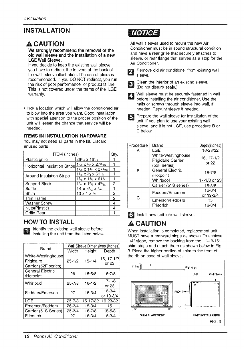
HOW TO iNSTALL
D Identify the existing wall sleeve before
installing the unit from the listed below.
Wall Sleeve Dimensions (inches',
Brand
Width Height Depth
White-Westinghouse
Frigidaire 25-1/2 15-1/4 16, 17-1/2
or 22
Carrier (52F series)
General Electric
/Hotpoint 26 15-5/8 16-7/8
Whirlpool 25-7/8 16-1/2 17-1/8
or 23
Fedders/Emerson 27 16-3/4 16-3/4
or 19-3/4
LGE 25-7/8 15-17/32 t6-23/32
Emerson/Fedders 26-3/4 15-3/4 15
Carrier (51S Series) 25-3/4 16-7/8 18-5/8
Friedrich 27 16-3/4 16-3/4
All wall sleeves used to mount the new Air
Conditioner must be in sound structural condition
and have a rear grille that securely attaches to
sleeve, or rear flange that serves as a stop for the
Air Conditioner,
Remove old air conditioner from existing wall
sleeve.
Clean the interior of an existing sleeve.
(Do not disturb seals.)
D all sleeve must be securely fastened in wall
before installing the air conditioner. Use the
nails or screws through sleeve into wall, if
needed. Repaint sleeve if needed.
D repare the wall sleeve for installation of the
unit. If you plan to use your existing wall
sleeve, and it is not LGE, use procedure B or
C below.
Procedure Brand Depth(inches)
A LG E 16-23/32
White-Westinghouse 16, 17-1/2
Frigidaire Carder
or 22
(52F series)
B General Electric
16-7/8
/Hotpoint
Whirlpool 17-1/8 or 23
Carder (51S series) 18-5/8
16-3/4
Fedders/Emerson
or 19-3/4
C
Emerson/Fedders 15
Friedrich 16-3/4
Q Install new unit into wall sleeve.
_, CAUTION
When installation is completed, replacement unit
MUST have a rearward slope as shown. To achieve
1/4" slope, remove the backing from the 11-13/16"
shim strips and attach them as shown below in Fig.
3. Place the higher portion of shim to the front of
the rib on base of wall sleeve.
UNIT Wall Sleeve
SHIM PLACEMENT UNIT INSTALLATION
FIG. 3
12 Room Air Conditioner
Installation
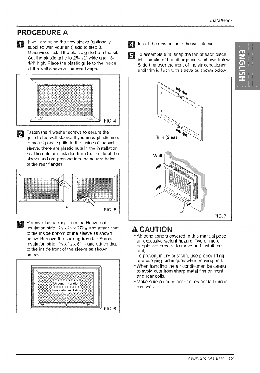
PROCEDURE A
D f you are using the new sleeve (optionally
supplied with your unit),skip to step 3.
Otherwise, install the plastic grille from the kit.
Cut the plastic grille to 25-1/2" wide and 15-
1/4" high. Place the plastic grille to the inside
of the wall sleeve at the rear flange.
li Install the new unit into the wall sleeve.
]To assemble trim, snap the tab of each piece
into the slot of the other piece as shown below.
Slide trim over the front of the air conditioner
until trim is flush with sleeve as shown below.
FIG. 4
] Fasten the 4 washer screws to secure the
grille to the wall sleeve. If you need plastic nuts
to mount plastic grille to the inside of the wall
sleeve, there are plastic nuts in the installation
kit. The nuts are installed from the inside of the
sleeve and are pressed into the square holes
of the rear flanges.
or
-- FIG. 5
Remove the backing from the Horizontal
Insulation strip 13/8x 3/8x 273/16 and attach that
to the inside bottom of the sleeve as shown
below. Remove the backing from the Around
Insulation strip 13_8x 3/4x 611/2 and attach that
to the inside front of the sleeve as shown
below.
FIG. 6
Trim (2 ea)
Wall
i
FIG. 7
,A CAUTION
• Air conditioners covered in this manual pose
an excessive weight hazard. Two or more
people are needed to move and install the
unit.
To prevent injury or strain, use proper lifting
and carrying techniques when moving unit.
• When handling the air conditioner, be careful
to avoid cuts from sharp metal fins on front
and rear coils.
• Make sure air conditioner does not fall during
removal.
Owner's Manual 13
Installation
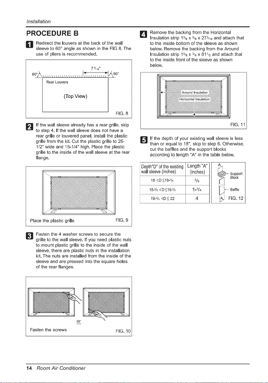
PROCEDURE B
D edirect the louvers at the back of the wall
sleeve to 60 ° angle as shown in the FIG 8. The
use of pliers is recommended.
7 5/46"
(Top View)
FIG.8
_]_ emove the backing from the Horizontal
Insulation strip 13/8 X 5/8X 273/16 and attach that
to the inside bottom of the sleeve as shown
below. Remove the backing from the Around
Insulation strip 13/8 x 3/4 x 611/2 and attach that
to the inside front of the sleeve as shown
below.
If the wall sleeve already has a rear grille, skip
to step 4. If the wall sleeve does not have a
rear grille or Iouvered panel, install the plastic
grille from the kit. Cut the plastic grille to 25-
1/2" wide and 15=1/4" high. Place the plastic
grille to the inside of the wall sleeve at the rear
flange.
Place the plastic grille
FIG. 9
FIG. 11
lf the depth of your existing wall sleeve is less
than or equal to 18", skip to step 6. Otherwise,
cut the baffles and the support blocks
according to length "A" in the table below.
Depth"D" of the existing Length "A"
wall sleeve (inches) (inches)
I8 <D_<18-% 314
18-% <D_<19-_/4 1=3/4
19-3/4<D _<22 4
A/i
_ Support
Block
_-- Baffle
FIG. 12
Fasten the 4 washer screws to secure the
grille to the wall sleeve. If you need plastic nuts
to mount plastic grille to the inside of the wall
sleeve, there are plastic nuts in the installation
kit. The nuts are installed from the inside of the
sleeve and are pressed into the square holes
of the rear flanges.
or
Fasten the screws
14 Room Air Conditioner
Installation
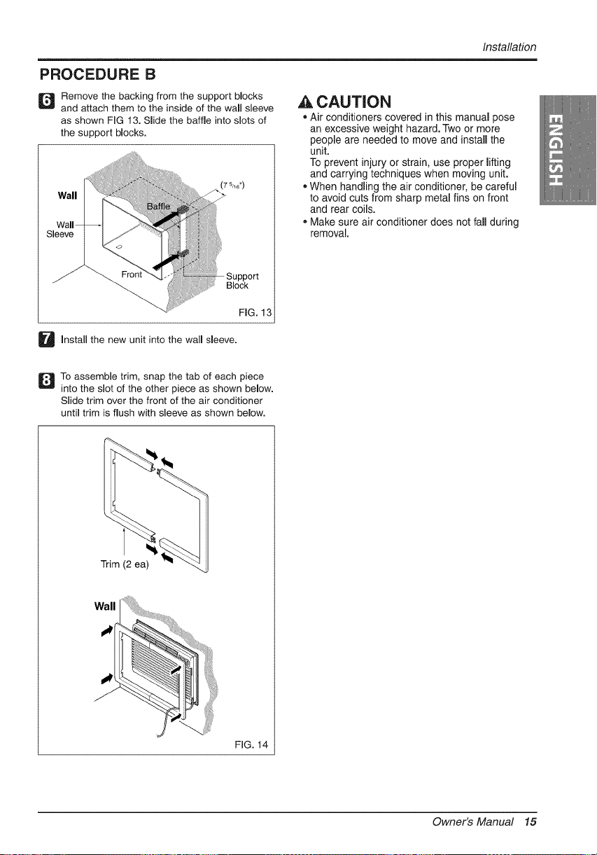
PROCEDURE B
] Remove the backing from the support blocks
and attach them to the inside of the wall sleeve
as shown FIG 13. Slide the baffle into slots of
the support blocks.
!ii!iiii:_:_........ (7_,,0,,)
ii,_i_iiiiii!i$iiii;:iiiiiilDi
_ Support
!iiiiiiii!ii%iiii_iii]iii!i!i!:!iiiiiiii':'_' Block
FIG. 13
,& CAUTION
• Air conditioners covered in this manual pose
an excessive weight hazard. Two or more
people are needed to move and install the
unit.
To prevent injury or strain, use proper lifting
and carrying techniques when moving unit.
• When handling the air conditioner, be careful
to avoid cuts from sharp metal fins on front
and rear coils.
• Make sure air conditioner does not fall during
removal.
U Install the new unit into the wall sleeve.
]To assemble trim, snap the tab of each piece
into the slot of the other piece as shown below.
Slide trim over the front of the air conditioner
until trim is flush with sleeve as shown below.
Trim (2 ea)
Wall
FIG. 14
Owner's Manual 15
Installation
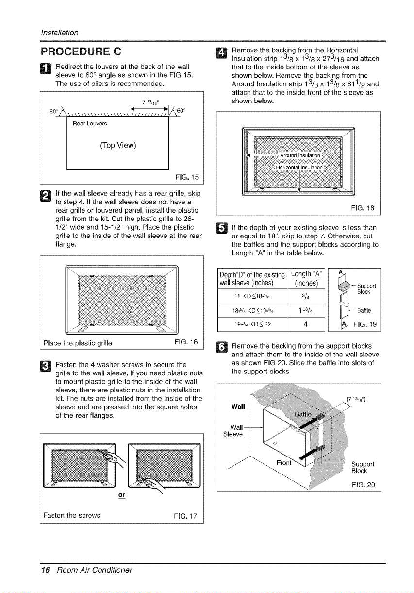
PROCEDURE C
D edirect the louvers at the back of the wall
sleeve to 60 ° angle as shown in the FIG 15.
The use of pliers is recommended.
7 13/1C
60_ ................... I__ 60°
Rear Louvers
(Top V ew)
FIG. 15
D f the wall sleeve already has a rear grille, skip
to step 4. If the wall sleeve does not have a
rear grille or Iouvered panel, install the plastic
grille from the kit. Cut the plastic grille to 26-
1/2" wide and 15-1/2" high. Place the plastic
grille to the inside of the wall sleeve at the rear
flange.
Place the plastic grille FIG. 16
Fasten the 4 washer screws to secure the
grille to the wall sleeve. If you need plastic nuts
to mount plastic grille to the inside of the wall
sleeve, there are plastic nuts in the installation
kit. The nuts are installed from the inside of the
sleeve and are pressed into the square holes
of the rear flanges.
or
Fasten the screws FIG. 17
D emove the backing from the Horizontal
Insulation strip 13/8 x 13/8 x 273/16 and attach
that to the inside bottom of the sleeve as
shown below. Remove the backing from the
Around Insulation strip 13/8 x 13/8 x 611/2 and
attach that to the inside front of the sleeve as
shown below.
FIG. 18
_lf the of sleeve is less than
depth your existing
or equal to 18", skip to step 7. Otherwise, cut
the baffles and the support blocks according to
Length "A" in the table below.
Depth"D" of the existing Length "A" ,_
- Support
wall sleeve (inches) (inches) _-/_ Block
18 <D_<18-5/8 3/4
18-% <D_<19-3/4 1 =3/4 T_I - Baffle
19-3/4<D_<22 4 _ FIG. 19
Q emove the backing from the support blocks
and attach them to the inside of the wall sleeve
as shown FIG 20. Slide the baffle into slots of
the support blocks
Support
Block
FiG. 20
16 Room Air Conditioner
Installation
PROCEDURE C
@
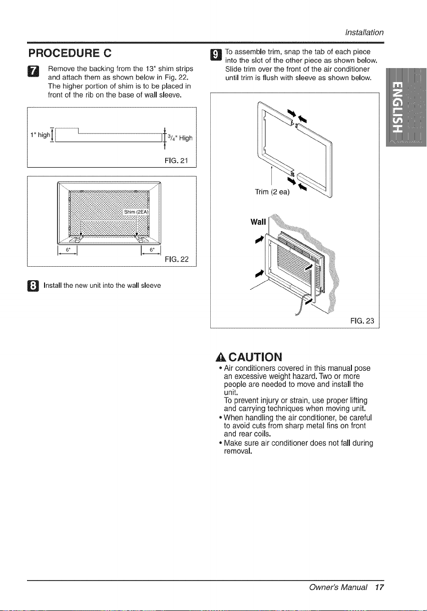
Remove the backing from the 13" shim strips
and attach them as shown below in Fig. 22.
The higher portion of shim is to be placed in
front of the rib on the base of wall sleeve.
1" high__ I-
II 3/4" High
FIG. 21
161
Install the new unit into the wall sleeve
FIG. 22
D o assemble trim, snap the tab of each piece
into the slot of the other piece as shown below.
Slide trim over the front of the air conditioner
until trim is flush with sleeve as shown below.
Trim (2 ea)
Wall
FIG. 23
A CAUTION
• Air conditioners covered in this manual pose
an excessive weight hazard. Two or more
people are needed to move and install the
unit.
To prevent injury or strain, use proper lifting
and carrying techniques when moving unit.
• When handling the air conditioner, be careful
to avoid cuts from sharp metal fins on front
and rear coils.
• Make sure air conditioner does not fall during
removal.
Owner's Manual 17
OperatingInstructions
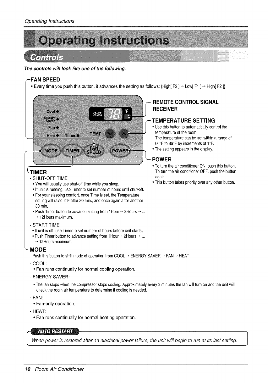
The controls will look like one of the foflowing.
-FAN SPEED
• Everytime you push this button,it advances the setting as follows: {High[F2] _ Low[F1 ] _ High[F2]}
(-TIMER
- SHUT-OFF TIME
• You will usually use shut-off time while you sleep.
• If unit is running, use Timer to set number of hours until shut-off.
• For your sleeping comfort, once Time is set, the Temperature
setting will raise 2°F after 30 min., and once again after another
30 rain.
• Push Timer button to advance setting from 1Hour * 2Hours _ ...
• 12Hours maximum.
- START TIME
• If unit is off, use Timer to set number of hours before unit starts.
• Push Timer button to advance setting from 1Hour * 2Hours _ ...
12Hours maximum.
MODE
REMOTECONTROLSIGNAL
RECEIVER
TEMPERATURE SETTING
• Use this button to automatically control the
temperature of the room.
The temperature can be set within a range of
60°F to 86°F by increments of I°F.
• The setting appears in the display.
POWER
• To turn the air conditioner ON, push this button.
To turn the air conditioner OFF, push the button
again.
• This button takes priority over any other button.
- Push this button to shift mode of operation from COOL _ENERGY SAVER * FAN * HEAT
- COOL:
• Fan runs continually for normal cooling operation.
- ENERGY SAVER:
• The fan stops when the compressor stops cooling. Approximately every 3 minutes the fan will turn on and the unit will
check the room air temperature to determine if cooling is needed.
- FAN:
• Fan-only operation.
- HEAT:
• Fan runs continually for normal heating operation.
_d after an electrical power failure, the unit will begin to run at its last setting. J
18 Room Air Conditioner
Operating Instructions
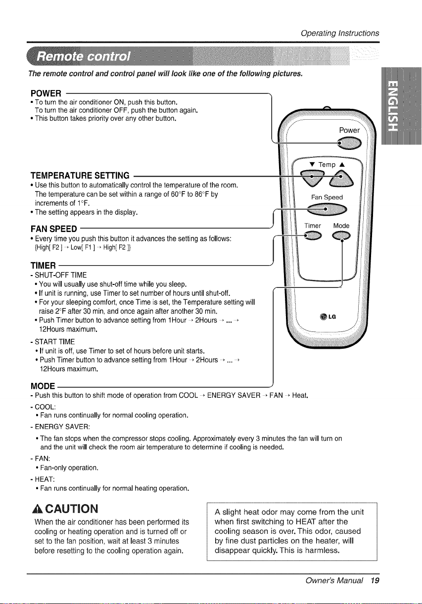
The remote control and control panel will leek like one of the following pictures.
POWER
• To turn the air conditioner ON, push this button.
To turn the air conditioner OFF, push the button again.
• This button takes priority over any other button.
TEMPERATURE SETTING
• Use this button to automatically control the temperature of the room.
The temperature can be set within a range of 60"F to 86°F by
increments of I°F.
• The setting appears in the display.
FAN SPEED
• Every time you push this button it advances the setting as follows:
{High[ F2 ] _Low[ F1 ] _High[ F2 ]}
TIMER
- SHUT-OFF TIME
• You will usually use shut-off time while you sleep.
• If unit is running, use Timer to set number of hours until shut-off.
• For your sleeping comfort, once Time is set, the Temperature setting will
raise 2°F after 30 rain, and once again after another 30 rain.
• Push Timer button to advance setting from 1Hour * 2Hours * ... *
12Hours maximum.
- START TIME
• If unit is off, use Timer to set of hours before unit starts.
• Push Timer button to advance setting from 1Hour * 2Hours * ... *
12Hours maximum.
Fan Speed
MODE
- Push this button to shift mode of operation from COOL _ ENERGY SAVER _ FAN * Heat.
- COOL:
• Fan runs continually for normal cooling operation.
- ENERGY SAVER:
• The fan stops when the compressor stops cooling. Approximately every 3 minutes the fan will turn on
and the unit will check the room air temperature to determine if cooling is needed.
- FAN:
• Fan-only operation.
- HEAT:
• Fan runs continually for normal heating operation.
,& CAUTION
When the air conditioner has been performed its
cooling or heating operation and is turned off or
set to the fan position, wait at least 3 minutes
before resetting to the cooling operation again.
A slight heat odor may come from the unit
when first switching to HEAT after the
cooling season is over. This odor, caused
by fine dust particles on the heater, will
disappear quickly. This is harmless.
Owner's Manual 19
OperatingInstructions
1. Remove the cover from the back of the remote
controller.
2. Insert two batteries.
• Be sure that the (+) and (-) directions are
correct.
• Be sure that both batteries are new.
3. Re-attach the cover.
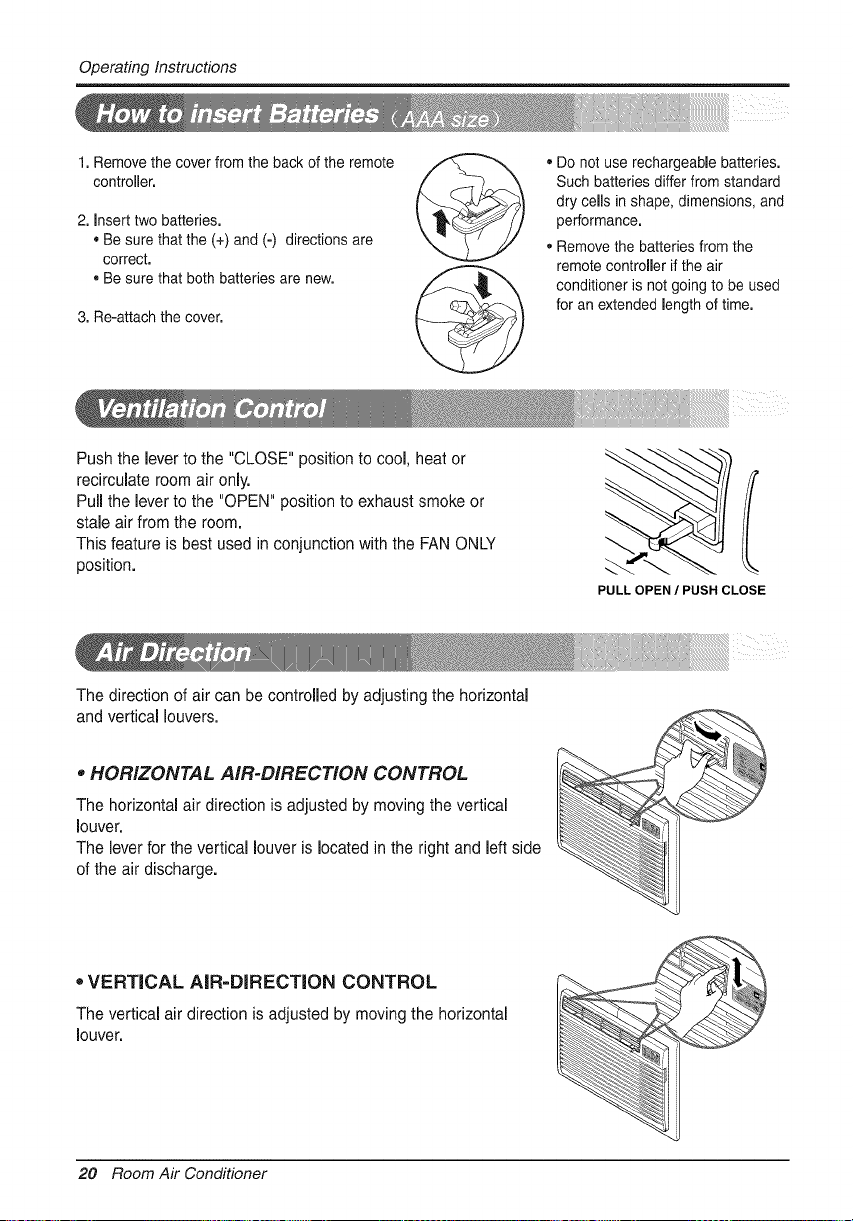
Push the lever to the "CLOSE" position to cool, heat or
recirculate room air only.
Pull the lever to the "OPEN" position to exhaust smoke or
stale air from the room.
This feature is best used in conjunction with the FAN ONLY
position.
Do not use rechargeable batteries.
Such batteries differ from standard
dry cells in shape, dimensions, and
performance.
• Remove the batteries from the
remote controller if the air
conditioner is not going to be used
for an extended length of time.
PULL OPEN / PUSH CLOSE
The direction of air can be controlled by adjusting the horizontal
and vertical louvers.
• HORIZONTAL AIR-DIRECTION CONTROL
The horizontal air direction is adjusted by moving the vertical
louver.
The lever for the vertical louver is located in the right and left side
of the air discharge.
,'VERTICAL AIR-DIRECTION CONTROL
The vertical air direction is adjusted by moving the horizontal
louver.
_MM
20 Room Air Conditioner
MaintenanceandService
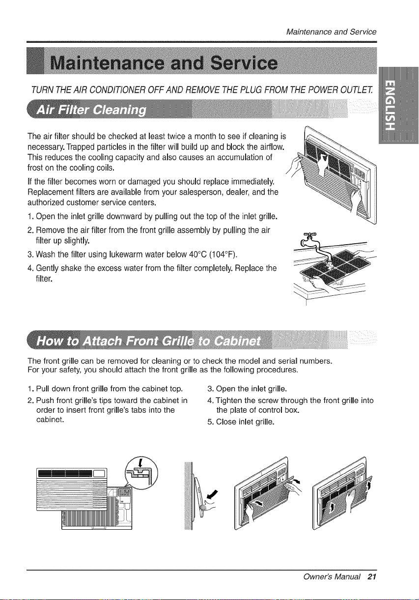
TURN THE AIR CONDITIONER OFF AND REMOVE THE PLUG FROM THE POWER OUTLET.
The air filter should be checked at least twice a month to see if cleaning is
necessary.Trapped particles in the filter will build up and block the airflow.
This reduces the cooling capacity and also causes an accumulation of
frost on the cooling coils.
If the filter becomes worn or damaged you should replace immediately.
Replacement filters are available from your salesperson, dealer, and the
authorized customer service centers.
1. Open the inlet grille downward by pulling out the top of the inlet grille.
2. Remove the air filter from the front grille assembly by pulling the air
filter up slightly.
3. Wash the filter using lukewarm water below 40°C (104°F).
4. Gently shake the excess water from the filter completely. Replace the
filter.
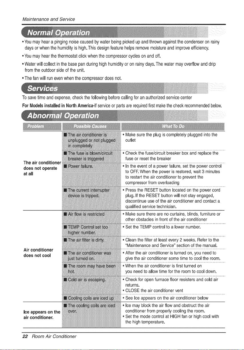
The front grille can be removed for cleaning or to check the model and serial numbers.
For your safety, you should attach the front grille as the following procedures.
1. Pull down front grille from the cabinet top.
2. Push front grille's tips toward the cabinet in
order to insert front grille's tabs into the
cabinet.
3. Open the inlet grille.
4. Tighten the screw through the front grille into
the plate of control box.
5. Close inlet grille.
Owner's Manual 21
MaintenanceandService
• You may hear a pinging noise caused by water being picked up and thrown against the condenser on rainy
days or when the humidity is high.This design feature helps remove moisture and improve efficiency.
• You may hear the thermostat click when the compressor cycles on and off.
o Water will collect in the base pan during high humidity or on rainy days. The water may overflow and drip
from the outdoor side of the unit.
, The fan will run even when the compressor does not.
To save time and expense, check the following before calling for an authorized service center
For Modelsinstalled in North America-Ifservice or parts are required first make the check recommended below.
The air conditioner
does not operate
at aii
Air conditioner
does not cool
ice appears on the
air conditioner=
• Make sure the plug is completely plugged into the
outlet
,, Check the fuse/circuit breaker box and replace the
fuse or reset the breaker
,, In the event of a power failure, set the power control
to OFF, When the power is restored, wait 3 minutes
to restart the air conditioner to prevent the
compressor from overloading
• Press the RESET button located on the power cord
plug. If the RESET button will not stay engaged,
discontinue use of the air conditioner and contact a
qualified service technician.
Make sure there are no curtains, blinds, furniture or
other obstacles in front of the air conditioner
• Set the TEMP control to a lower number.
• Clean the filter at least every 2 weeks. Refer to the
"Maintenance and Service" section of the manual.
• After the air conditioner is turned on, you need to
give the air conditioner some time to cool the room.
,,When the air conditioner is first turned on
you need to allow time for the room to cool down.
,, Check for open furnace floor resisters and cold air
returns.
= CLOSE the air conditioner vent
,, See Ice appears on the air conditioner below
• Ice may block the air flow and obstruct the air
conditioner from properly cooling the room.
Set the mode control at HiGH fan or high cool with
the high temperature.
22 Room Air Conditioner
Memo
Owner'sManual23
,P
a,
PARA SUS ARCHIVES
Escriba aqd el modelo y nt_mero de serie:
Modelo n°:
Serie n°:
Puede encontrar estos dates en la etiqueta situada en el lateralde
cada unidad,
Nombre del distribuidor:
Fecha de compra:
[] Adjunte su recibo a esta p_gina con ia grapadora pars ei
memento que Io necesite para probar la fecha de su adquisici6n
o pars la validaci6n de la garantia.
LEA ESTE MANUAL
En su interior encontrara muchos consejos utiles sobre la utilizaci6n
y mantenimiento de su acondicionador de aire. Unos pocos
cuidados per su parte le pueden ahorrar touche tiempo y dinero
durante la vida de su acondicionador de sire.
En la tabla de consejos para la soluci6n rbLpida de problemas
encontrara muchas respuestas a los problemas mAs habituales. Si
revisa primero nuestra Tabla de Consejoa para la soluci6n r_.pida
de problemas, tal vez no necesite Ilamar nunca al servicio t_cnico.
PRECAUCION
= P6ngase en contacto con un t_cnico del servicio
autorizado para rea|izar la reparacibn y mantenimiento
de esta unidad.
• P6ngase en contacto con un instalader pars realizar la
instalaci6n de ests unidad.
• Cuando se va a cambiar el cable e|_ctdco, el trabajo
de reempiazamiente debe ser realizado _nicamente
per personal autorizado, utiiizando las piezas de
cambio genuinas _nicamente,
° El trabajo de reemplazamiento debe ser rea|izado de
acuerdo con el Cbdige El_ctrico Nacional _nicamente
per personal auterizado.
2 Aire Acondicionado
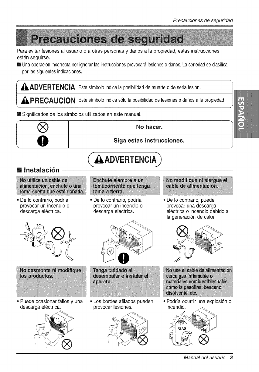
Precaucionesdeseguridad
Para evitar lesiones al usuario o a otras personas y dahos a la propiedad, estas instrucdones
est_n seguirse.
[] Unaoperaci6nincorrectaporignorarlas instruccionesprovocaralesioneso daSos.La seriedadse dasifica
porlas siguientesindicaciones.
, kADVERTENClA Estesimboloindicala posibilidaddemuerteo de serialesi6n.
PREOAUCION Estesfmboloindicas61ola posibilidadde lesioneso daSosa la propiedad
[] Significados de los simbolos utilizados en este manual.
®
I.
[] Instalaci6n
• De Io contrario, podria
No hacer.
Siga estas instrucciones.
provocar un incendio o
descarga el6ctrica.
• Puede ocasionar fallos y una
descarga electrica.
• De Io contrario, podria
provocar un incendio o
descarga el_ctrica.
o Los bordes afilados pueden
provocar lesiones.
• De Io contrario, puede
provocar una descarga
el_ctrica o incendio debido a
la generaci6n de calor.
• Podria ocurrir una explosi6n o
incendio.
®
Manual del usuario
Precaucionesdeseguridad
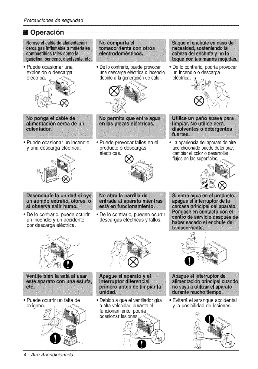
m Operaci6n
• Puede ocasionar una
explosi6n o descarga
el_ctrica.
DeIo contrario,puedeprovocar
unadescargael_ctricao incendio
debidoa la generaci6nde calor.
De Io contrario,podria provocar
un incendioo descarga
electrica.
• Puede ocasionar un incendio
y una descarga electrica.
• De Io contrado, puede ocurrir
• Puede provocarfallos en el
producto o descargas
electricas.
• Laaparienciadelaparatode aire
acondicionadopuededeteriorar,
cambiarelcoloro desarrollar
flujosen lassuperficies.
®
un incendio y un accidente
por descarga el_ctrica.
,, Puede ocurrir un falta de
oxigeno.
• De Io contrario, pueden ocurrir
descargas el6ctricas y fallos.
• Debidoa que el ventiladorgira
a alta velocidadduranteel
funcionamiento,podria
ocasionarlesiones.
4 Aire Acondicionado
• Evitara el arranque accidental
y la posibilidad de lesiones.
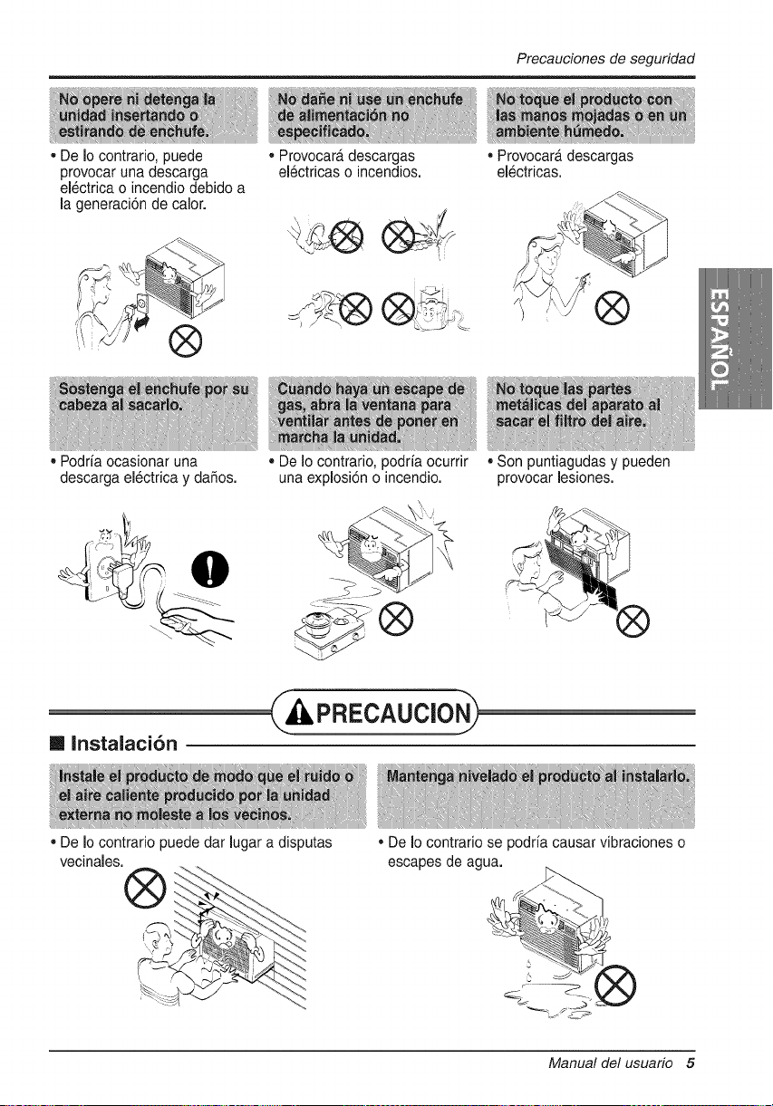
Precauciones de seguridad
• De Io contrario, puede
provocar una descarga
el_ctrica o incendio debido a
la generaci6n de calor.
®
• Podrfa ocasionar una
descarga electdca y dafios.
• Provocara descargas
el_ctdcas o incendios.
[] Instalaci6n
• De Io contrario, podria ocurrir
una explosi6n o incendio.
C PRECAUCIONj
• De Io contrario puede dar lugar a disputas
vecinales.
• ProvocarD.descargas
el_ctricas.
, Son puntiagudas y pueden
provocar lesiones.
• De Io contrario se podrfa causar vibraciones o
escapes de agua.
Manual delusuar_ 5
SafetyPrecautions
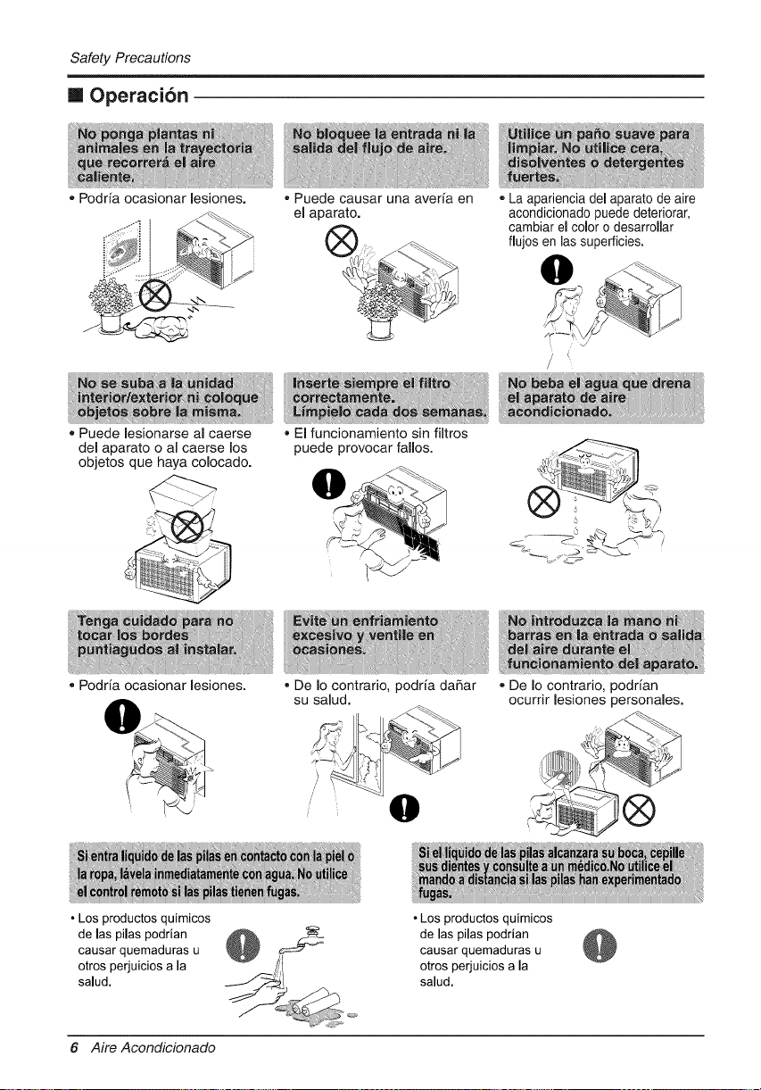
[] Operacion
o Podfia ocasionar lesiones. = Puede causar una aveda en
el aparato.
La apariencia del aparato de aire
acondidonado puede deteriorar,
cambiar el color o desarrollar
flujos en las superficies.
Puede lesionarse al caerse
del aparato o al caerse los
objetos que haya colocado.
Podria ocasionar lesiones.
El funcionamiento sin filtros
puede provocar fallos.
= De Io contrario, podria dahar
su salud.
1
• Los productos qutmicos
de las pilas podrian
causar quemaduras u
otros perjuicios a la
salud,
• De Io contrario, podrfan
ocurrir lesiones personales.
• Los productos quimicos
de las pilas podrian
causar quemaduras u
otros perjuicios a la
salud,
6 Aire Acondicionado
AntesdelaOperacidn
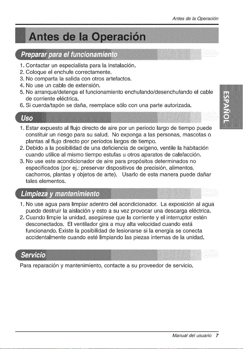
1. Contactar un especialista para la instalaci6n.
2. Coloque el enchufe correctamente.
3. No comparta la salida con otros artefactos.
4. No use un cable de extensi6n.
5. No arranque/detenga el funcionamiento enchufando/desenchufando el cable
de cordente el6ctrica.
6. Si cuerda/tap6n se daRa, reemplace s61o con una parte autorizada.
1. Estar expuesto al flujo directo de aire por un perfodo largo de tiempo puede
constituir un desgo para su salud. No exponga alas personas, mascotas o
plantas al fiujo directo por periodos largos de tiempo.
2. Debido a la posibilidad de una deficiencia de oxigeno, ventile la habitaci6n
cuando utilice al mismo tiempo estufas u otros aparatos de calefacci6n.
3. No use este acondicionador de aire para prop6sitos determinados no
especificados (pot ej.: preservar dispositivos de precisi6n, alimentos,
cachorros, plantas y objetos de arte). Usado de esta manera puede da5ar
tales elementos.
1. No use agua para Iimpiar adentro del acondicionador. La exposici6n al agua
puede destruir la aislaci6n y esto a su vez provocar una descarga el_ctrica.
2. Cuando limpie la unidad, asegQrese que la corriente y el interruptor est_n
desconectados. El ventilador gira a muy alta velocidad cuando est#.
funcionando. Existe la posibilidad de lesionarse si la energia se conecta
accidentalmente cuando est6 Iimpiando las piezas internas de la unidad.
Para reparaci6n y mantenimiento, contacte a su proveedor de servicio.
Manual del usuario 7
Introduccidn
&
a,
Este simbolo Io advierte de un peligro de accidente por
corriente el_ctrica,
Este simbolo Io adiverte de un peligro que pueda causar un
daho del ventliador.
Este sirnbolo significa condicciones especiales.
_ ADVERTENCIA
Este aparato deberia instalarse de acuerdo con las normas del CSdigo EI6ctrico Nacional.
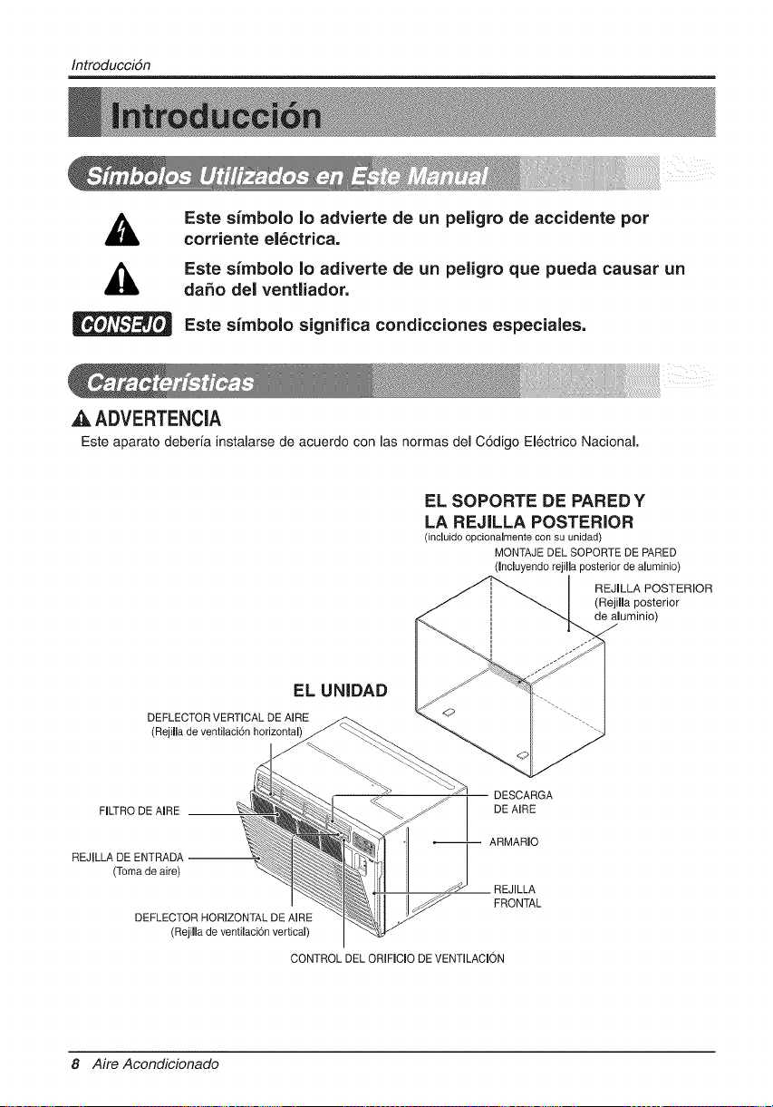
EL SOPORTE DE PAREDY
LA REJILLA POSTERIOR
(incluido opcionalmente con su unidad)
MONTAJE DEL SOPORTE DE PARED
(Incluyendo rejilla posterior de aluminio)
REJILLA POSTERIOR
(Rejifla posterior
de aluminio)
EL UN|DAD
DEFLECTOR VERTICAL DE AIRE
(Rejilla de ventilaci6n horizontal
DESCARGA
FILTRO DE AIRE DE AIRE
ARMARIO
REJILLA DE ENTRADA --
(Toma de aire)
REJILLA
FRONTAL
DEFLECTOR HORIZONTAL DE AIRE
(Rejilla de ventilaci6n vertical)
CONTROL DEL ORIFICIO DE VENTILACION
8 Aire Acondicionado
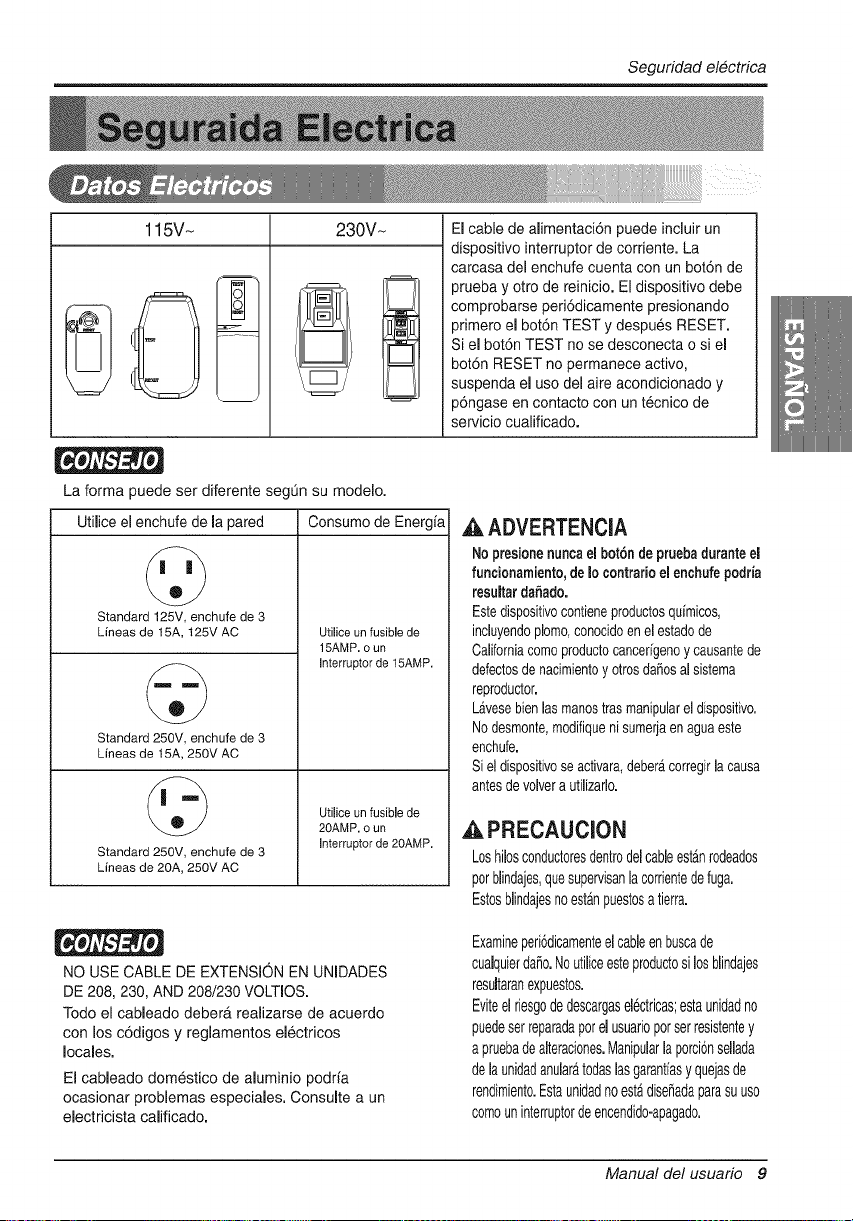
Seguridadel#ctrica
115V~ 230V~ El cable de alimentaci6n puede incluir un
dispositivo interruptor de corriente. La
carcasa del enchufe cuenta con un bot6n de
prueba y otto de reinicio. El dispositivo debe
comprobarse peri6dicamente presionando
primero el bot6n TEST y despues RESET.
Si el bot6n TEST no se desconecta o si el
bot6n RESET no permanece activo,
suspenda el use del aire acondicionado y
p6ngase en contacto con un tecnico de
servicio cualificado.
La forma puede set diferente segun su modelo.
Utilice el enchufe de la pared Consumo de Energia
©
Standard 125V, enchufe de 3
Lineas de 15A, 125V AC
©
Standard 250V, enchufe de 3
Lineas de 15A, 250V AC
Standard 250V, enchufe de 3
Lineas de 20A, 25OV AC
UtiUice un fusible de
15AMP. o un
Unterruptor de 15AMP.
Utilice un fusible de
20AMP. o un
Interruptor de 20AMP.
,,&ADVERTENCIA
No presionenunca el bot6nde pruebaduranteel
funcionamiento,de Io contrario el enchufepodria
resultardaSado.
Estedispositivocontieneproductosquimicos,
incluyendoplomo,conocidoenel estadode
Californiacomoproductocancerigenoy causantede
defectosde nacimientoy otrosdaSosal sistema
reproductor.
Lb,vesebienlas manostrasmanipularel dispositivo.
Nodesmonte,modifiqueni sumerjaen aguaeste
enchufe.
Si eldispositivoseactivara,deberacorregirla causa
antesde volvera utilizarlo.
,&PRECAUClON
Loshilosconductoresdentrodelcableest_.nrodeados
per blindajes,quesupervisanh corrientedefuga.
Estosbhdajesnoestanpuestosa tierra.
NO USE CABLE DE EXTENSION EN UNIDADES
DE 208, 230, AND 208/230 VOLTIOS.
Todo el cableado deber_, realizarse de acuerdo
con los codigos y reglamentos electricos
locales.
El cableado domestico de aluminio podr_a
ocasionar problemas especiales. Consulte a un
electricista calificado.
Examineperi6dicamenteelcableenbuscade
cualquierdaSo.Noutiliceesteproductosilosblindajes
resultaranexpuestos.
Eviteel riesgodedescargasel6ctricas;estaunidadno
puedeserreparadaperelusuarioporserresistentey
apruebadealteraciones.Manipularh porci6nselhda
delaunidadanularatodashsgarantiasy quejasde
rendimiento.EstaunidadnoestAdise_adaparasuuso
comouninterruptordeencendido-apagado.
Manual delusuar_ 9
Seguridadelectrica
IMPORTANTE
(FAVORLEA CON ATENCK_N)
PORLASEGURIOADPERSONALDELUSUARIO,ESTE
APARATODEBESERDEB[DAMENTENEUTRALIZADO.
El cord6n de energia de 6ste aparato esta equipado
con tres patas(cabb a tierra). Utilice 6ste con un
enchufe de pared de tres salidas(a tierra) para
minimizar el peligro de choque el6ctrico. El cliente
debe revisar el receptor de pared y el circuito por un
electricista calificado para asegurarse que la
recepci6n esta debidamente neutralizada.
NO CORTEO REMUEVALA TERCERAPATA(GROUND)
DEL ENCHUFE.
A, SITUACIONES EN LAS CUALES EL APARATO
ES DESCONECTADO OCASIONALIVlENTE:
Debido al peligro potencial, nosotros no
recomendamos el use de adaptadores. Sin embargo,
si usted desea utilizar un adaptador, una CONEXION
TEMPORAL, puede ser
efectuada. Utilice adaptadores UL, disponibles en la
mayofia de los estabb cimientos de
herramientas. La pata mas grande del adaptador
debe set alineada con la pata mas grande del
interruptor para asegurarse una polarizaci6n
adecuada.
_,PRECAUCION
Adaptar la terminal del ground del adaptador a
la cubierta de la pared con un
tornillo no neutraliza el aparato a menos que la
cubierta del tornillo sea de metal, u no sea
insolada, y el receptor de pared este
neutralizado a trav6s del alambrado del la casa.
El cliente debe hacer verificar el circuito pot un
electdcista calificado para asegurarse que el
receptor esta debidamente neutralizado.
Desconecte el cord6n de energia del adaptador,
utilizado una mano en cada uno. De Io contrario, la
terminal del adaptador puede romperse.NO UTILICE el
aparato con un enchufe rot&
B. SiTUACIONES EN LAS CUALES EL APARATO
ES DESCONECTADO CON
FRECUENCIA,
No utilice un adaptador en estas circunstancias.
Desconectar el cord6n de energfa con frecuencia Io
IlevarA al eventual rompimiento de la terminal de
neutralizaci6n. La saluda de energia de la pared
debe ser reemplazada per una salida de tres
patas(neutralizada).
USO DE EXTENSIONES
Debido al peligro potencial, no recomendamos la
utilizaci6n de extensiones. Sin embargo, si usted
desea utilizar una extensi6n, utilice una
certificada por CSA/UL de tres alambres,
catalogada 20A, 250V.
10 Aire Acondicionado
Instalacidn
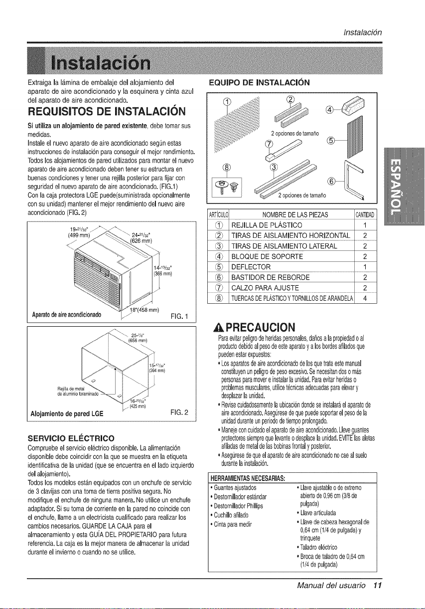
Extraiga la lamina de embalaje del alojamiento del
aparato de aire acondicionado y la esquinera y cinta azul
del aparato de aire acondicionado.
REQUISITOS DE INSTALACI6N
Si utiliza un alojamiento de pared existente,debe tomarsus
medidas.
Instaleel nuevoaparato de aire acondicionadosegOnestas
instruccionesde instalaci6npara conseguir el mejor rendimiento.
Todos losalojamientosde pared utilizados para montar el nuevo
aparato de aire acondicionado debentener su estructura en
buenas condicionesy tener una rejilla posterior para fijar con
seguridad el nuevoaparato de aire acondicionado. (FIG.l)
Con la caja protectoraLGE puede(suministradaopcionalmente
con su unidad) mantener el mejor rendimientodel nuevoaire
acondicionado (FIG.2)
Aparatodeaireacondi¢ionado FIG. 1
(394 ram)
(425mm)
Alojamientode pared LGE FIG. 2
SERVICIO ELECTRICO
Compruebe el servicioelectrico disponible.La alimentaci6n
disponible debe coincidir con la que se muestraen la etiqueta
identificativade la unidad (que se encuentraen el lado izquierdo
del alojamiento).
Todos los modelos estAnequipados con un enchufe de servicio
de 3 davijas con una toma de tierra positivasegura. No
modifiqueel enchufe de ninguna manera.No utilice un enchufe
adaptador.Si su toma de corrienteen la pared no coincide con
el enchufe, Ilamea un electricistacualificado para realizar los
cambios necesarios.GUARDELA CAJA para el
almacenamiento y esta GU[A DEL PROPETARIO para futura
referencia.La caja es la mejor manera de almacenar la unidad
durante el invierno o cuando no se utilice.
EQUIPO DE INSTALACI()N
2opdonesdetamaSo
2 opdones de tamaSo
ARTiCUL0 NOMBREDE LASPIEZAS :ANTIDAD
REJILLA DE PLASTICO 1
........_ T!RAS DE A!SLAMENTO HORIZONTAL ............2 ........
_3_ TIRAS DE AISLAMIENTO LATERAL 2
_4) BLOQUE DE SOPORTE 2
......._5_ DEFLECTOB ...........................................................................................................................................................
BASTIDOR DE REBORDE
........ c USTE............................................................................
TUERCASDEPLASTICOYTORNILLOSDEARANDELA 4
,& PRECAUCION
Para6vitarpeligrodeheridaspereonales,daSosa h propiedado al
productodebidoalpesode6steaparatoy alosbordesafiladosqu6
puedenestarexpuestos:
, Losaparatosdeaireacondicionadodelosquetrataestemanual
constituyenunpeligrodepesoexcesivo.$6necesitandoso mas
personasparamovereinstahrh unidad.Paraevitarheddaso
problemasmuscuhres,utilicet_cnicasadecuadasparaelevary
desplazarlaunidad.
, Revisecuidadosamentelaubicaci6ndondeseinstalaraelaparatode
aireacondicionado.AsegQresedequepuedesoportarelpesodela
unidadduranteunperiododetiempoprolongado.
° Manejeconcuidadoel aparatodeaireacondicionado.Lleveguantes
protectoressiemprequelevanteodesphcelaunidad.EVITElasaletas
afihdasdemetalde lasbobinasfrontaly posterior.
° Aseguresedequeel aparatodeaireacondicionadonocaealsu61o
durantela instalaci6n.
HERRAMIENTASNECESARIAS:
, Guantesajustados
. Destomilladorestandar
, DestornilladorPhillips
, Cuchilloafilado
.Cinta paramedir
, Llaveajustableo deextremo
abiertode0,96cm(3/8de
pulgada)
, Uavearticulada
, Uavedecabezahexagonalde
0,64cm(1/4depulgada)y
trinquete
, Taladroelectrico
, Brocade taladrode0,64cm
(1/4depulgada)
Manual del usuario 11
Instalacidn
INSTALAClON
A. PRECAUCION
Se recomienda encarecidamente la extracci6n de[
antiguo alojamiento en la pared y la instalaci6n de un
nuevo aiojamiento de pared Comfort-Aim.
Si decide mantener el alojamiento de pared
existent& tendra que ajustar la direccidn de la rejilla
en la parte posterior de la ilustracidn del alojamiento
de pared, Se recomienda el uso de tenazas, Si NO
ajusta la direccidn, corre el riesgo de un rendimiento
pobre o de fallo del product& Este hecho no esta
cubierto bajo los terminos de la garantfa de Comfort-
Aire.
. Si decide mantener el aJojamientode pared existente,tendra
que ajustar la direcci6n de [a rejiiia en la parte posteriorde la
ilustracidndel alojamientode pared.Se recomiendael uso de
tenazas. Si NO ajusta la direccidn,corre el riesgo de un
rendimientopobreo de fallo del producto. Este hechono est_
cubierto bajo los t6rminos de [a garantia de LGE.
ARTiCULOS EN EL 5QUIPO DE INSTALAClON
Puede que no necesite todas las partes de[ equipo de
instalaci6n.Tire [as piezas que no utilice.
ART{CULO
Rejillade plastico
Tgasdeaislamientohorizontal
Tgasdeaislamientolateral
81oquedesoporle
Deflector
Calzoparaajuste
Bastidorde reborde
Toreinodearandela
Tuercas(plastico)
Parteposteriorde h rejilla
3,81x 2,54x 210,03cm(263/_x t6_/_)
3,5 x1,52x69,03cm (fa/ax 5/8x 273/,o)
3,5 x3,5x 6903 cm(13/_x13/8x273/*_)
3,5 x2,03x 153,035(13/6x3/4x 61_/2)
3,5 x3,5x 153,035(13/8x 13/_x61_/2)
8,89x 3,5x 10,94cm (13/4x 13/6x 45/*e)
35,56x 11,43x 0,33(14 x #/2 x Vs)
33,02x 2,54x2,03(13 xI x 3/4)
Todos los alojamientosde pared utilizados para montar el
nuevoaparato de aire acondicionadodeben estar en buenas
condicionesestructuralesy tener una rejilla posterior que se
una con seguridadal alojamiento o un flanco posterior que
sirva de tope al aparato de aire acondicionado,
[ xtraiga el antiguoaparato de aire acondicionadodel
alojamiento de pared ya existente.
[ impieel interiordel aiojamientode pared ya existente.
(Notoque los selhdos.)
D Ialojamiento de pared debeestar bien fijado a la pared
antes de instalarel aparato de aire acondicionado. Sifuera
neeesario,utilice losclavos o tornillos para fijar el
aiojamiento a la pared.
- Vuelvaa pintar el alojamiento si fuera necesario.
Prepare el alojamientode paredpara la instalaci6nde la
unidad. Si pretendeutilizar una caja de paredde la que ya
dispone y no es LGE, utilice el procedimientoB o C que se
muestra a continuaci6n:
Procedimiento Marca
A LGE
;aiidad White-Westinghouse
1 FrigidaireCarrier
1 (52Fseries)
1 B GeneralElectric
1 /Hotpoint
1 Whirlpool
2 Carrier(51S series)
1 Fedders/Emerson
2 C Emerson/Fedders
2 Friedrich
4
4
1
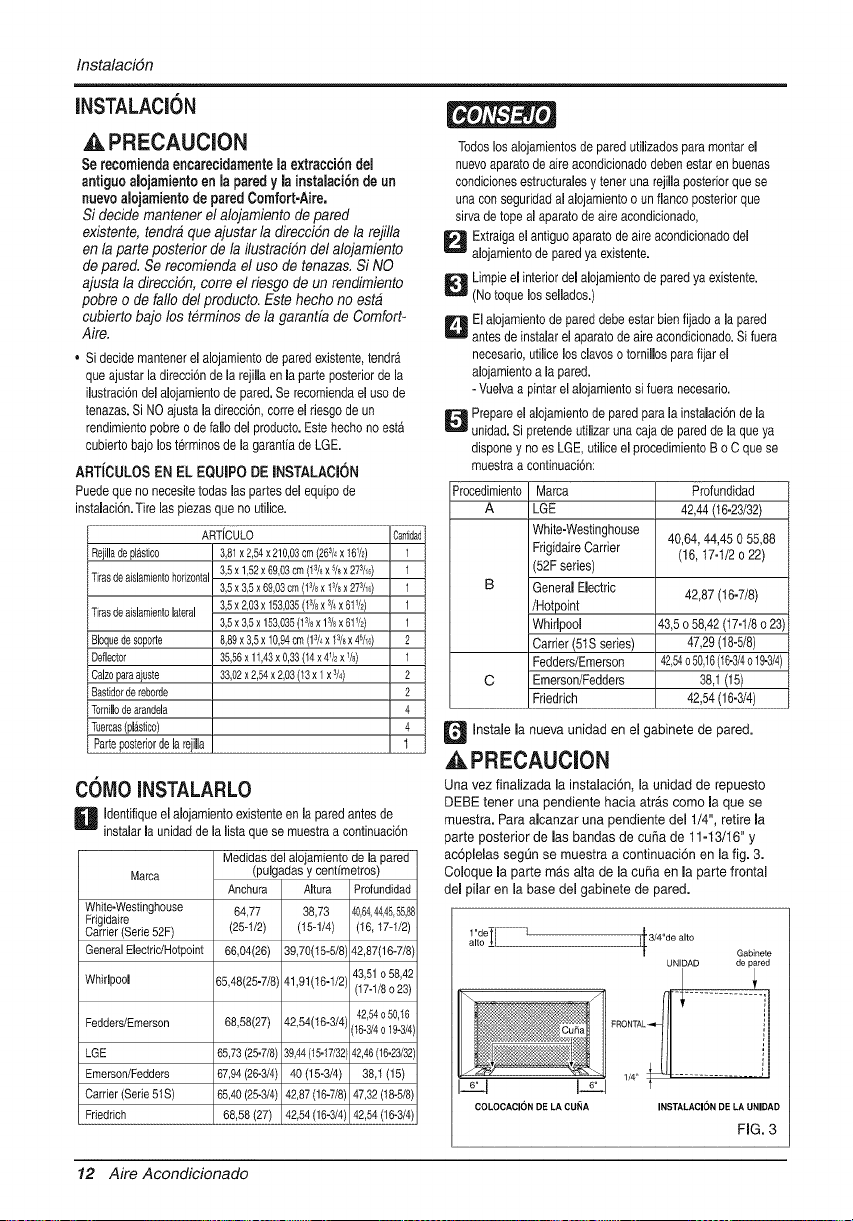
COMO iNSTALARLO
D Identifiqueel alojamiento existenteen la paredantes de
instalar [a unidad de la lista que se muestra a continuaci6n
Medidasdel alojamientode la pared
(pulgadas y centfmetros)
Marca
Anchura Altura Profundidad
White-Westinghouse 64,77 38,73 40,64,44,45,55,88
Frigidaire
Carrier (Serie 52F) (25-1/2) (15-1/4) (16, 17-1/2)
General ElectridHotpoint 66,04(26) 39,70(15-5/8' 42,87(16-7/8)
43,51 o 58,42
Whirlpool 65,48(25-7/8) 41,91(I6-1/2', (17-1/8 o 23)
42,54o50,16
Fedders/Emerson 68,58(27) 42,54(16-3/4' (16-3/4o 19-3/4)
LGE 65,73 (25-7/8) 39,44(15-17/32[42,46(16-23/32)
Emerson/Fedders 67,94(26-3/4) 40 (15-3/4) 38,1 (15)
Carrier(Serie51S) 65,40(25-3/4) 42,87(16-7/8) 47,32(18-5/8)
Friedrich 68,58 (27) 42,54 (16-3/4) 42,54 (16-3/4)
Profundidad
42,44(t6-23/32)
40,64, 44,45 O55,88
(16,17-1/2 o 22)
42,87 (16-7/8)
43,5 o58,42(17-1/8o 23)
47,29(18-5/8)
42,54o50,16(16-3/4o19-3/4)
38,1(15)
42,54(16-3/4)
Q Instale la nueva unidad en el gabinete de pared.
,APRECAUCION
Una vez finaiizada [a instaiaci6n, [a unidad de repuesto
DEBE tener una pendiente hacia atr_.s como [a que se
muestra. Para alcanzar una pendiente del 1/4", retire la
parte posterior de las bandas de cuffa de 11-13/16" y
ac6plelas segQn se muestra a continuaci6n en la fig. 3.
Coloque la parte mas alta de la cuffa en la parte frontal
del pilaf en la base del gabinete de pared.
1 "de-
t
j_[3/4"de alto
t Gabinete
UNLOAD de pared
t
COLOCACI(_N DE LA CUNA INSTALACI()N DE LA UNIDAD
FIG. 3
12 Aire Acondicionado

PROCEDIMIENTO A
D i est_ utilizandola nueva funda (suministrada
opcionalmentecon su unidad),vaya directamenteal paso 3.
Encaso contrario, instale la rejilJaplastica del equipo.Corte
la rejilla de pl_sticoa 64,77 cm (25-1/2) de anchoy 38,74
cm (15-1/4)de alto. Coloquela rejilla de pl_sticoen el
interiordel alojamientode pared, en el fiance posterior.
FIG. 4
_ Apriete Jos 4 torniJJosde arandeJa Japara
fijar rejilla
al alojamiento de pared. Si necesita tuercas de
pAstico para montar la rejilla de plastico en eJ
interior del alojamiento, hay tuercas de pl_stico en el
equipo de instalaci6n. Las tuercas se instaJan desde
eJinterior del alojamiento y se introducen
apret_ndolas en Jos orificios cuadrados de los
flancos traseros.
_ Extraiga Ja de la tira de AisJamientoparte posterior
horizontal de 3,5 x 0,96 x 69,06 cm (13/8x 3/5x
273h6) y fijela a la parte inferior intema del
aiojamiento seg0n se muestra abajo. Extraiga la
parte posterior de la tira de AisJamiento Jateral de
3,5 x 1,9 x 156,21 cm (13/8x 3/4x 611/2) y fijela al
interior deJ alojamiento segQn se muestra abajo.
FIG. 6
InstalaciSn
_ Instale la nueva unidad en el alojamiento de la pared.
Para montar el reborde, inserte el saliente de cada
pieza en la ranura de la otra pieza segOn se muestra
abajo. Deslice el reborde sobre la parte frontal del
aparato de aire acondicionado hasta que el reborde
este unido a paso con el alojamiento segOn se
muestra a continuaci6n.
Adorno (2ea)
Pa_ed
......................_iiiiiiiiiiiiiiiiii,,,_,¸....
iiiliii i....
FIG. 7
,A PRECAUCION
• Los aparatos de aire acondicionado de los que trata
este manuaJ constituyen un peiigro de peso excesivo.
Se necesitan dos o m_s personas para mover e
instaJar la unidad. Para evitar heridas o problemas
musculares, utilice t6cnicas adecuadas para eievar y
desplazar la unidad.
• AI manejar el aparato de aire acondicionado, tenga
cuidado de evitar cortes de las aletas afiladas de
metal en las bobinas frontal y trasera.
• AsegQrese de que el aparato de aire acondicionado
no se cae durante la instaiaci6n.
Manual del usuario 13
Instalaci6n
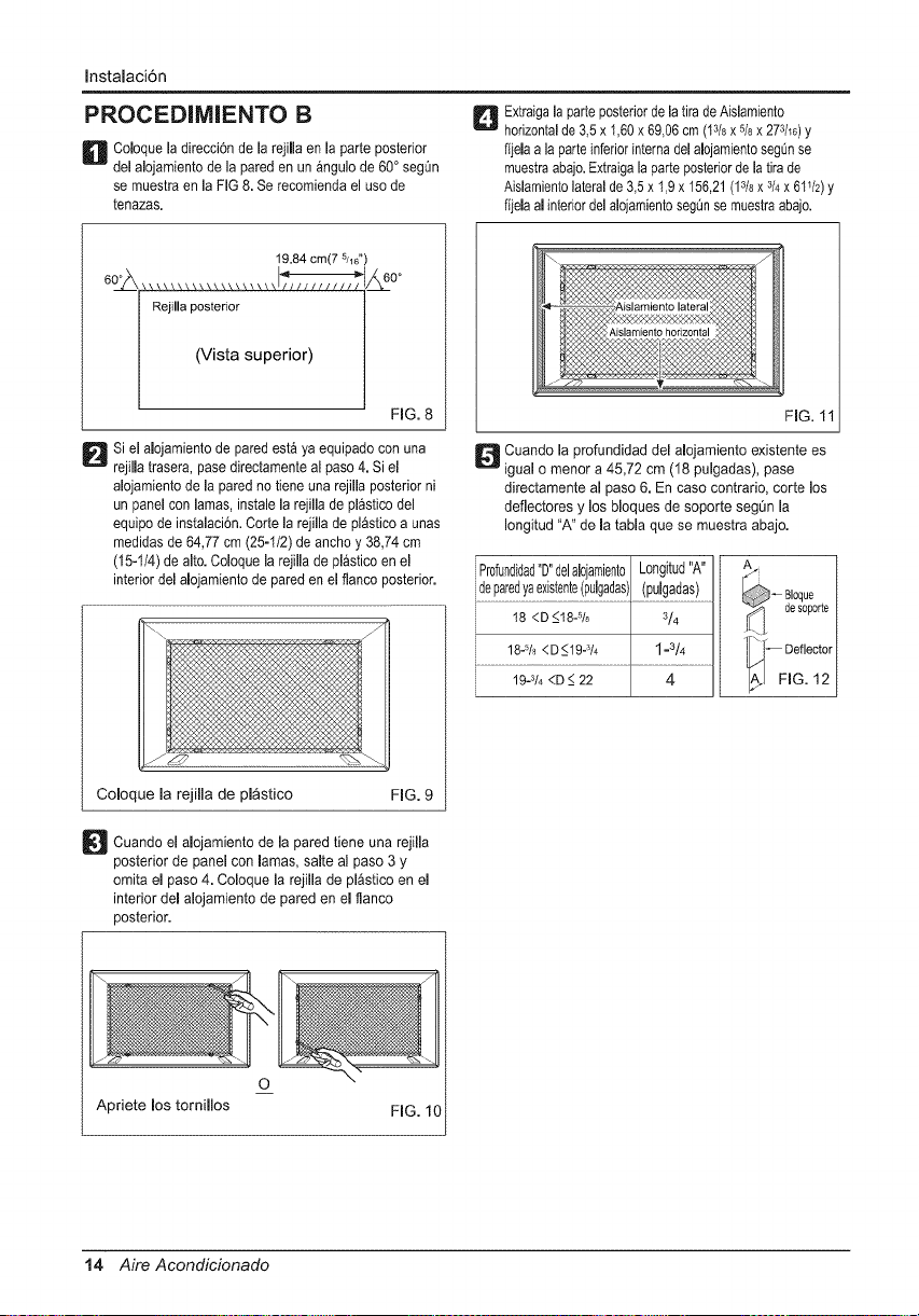
PROCEDIMIENTO B
D obque la direcci6n de la rejilla en la parte posterior
del alojamiento de la pared en un _ngulo de 60° segQn
se rnuestra en la FIG 8. Se recomienda el uso de
tenazas.
_ xtraiga la parte posteriorde la tirade Aislarniento
horizontalde 3,5 x 1,60x 69,06 cm (13/_x 5/8x 273h6)y
fijela a la parte inferior internadel aDjamiento segQnse
muestraabajo.Extraigala parte posterior de la tira de
Aislamiento lateralde 3,5 x 1,9 x 156,21 (13/8x 3/4x 61V2)y
fijela al interior del alojarnientosegQnse rnuestra abajo.
19,84 cm(7 5J16'
Rejilla posterior
(V sta super or)
_60 °
FIG. 8
Si el alojarniento de pared est& ya equipado con una
rejilla trasera, pase directamente al paso 4. Si el
alojamiento de la pared no tiene una rejilla posterior ni
un panel con lamas, instale la rejilla de pl_stico del
equipo de instalaci6n. Corte la rejilla de pl_stico a unas
medidas de 64,77 cm (25-I/2) de ancho y 38,74 cm
(15-1/4) de alto. Coloque la rejilla de pl_stico en el
interior del aDjamiento de pared en el flanco posterior.
Coloque la rejilla de pl_stico
FIG. 9
_Cuando alojarniento pared una rejilla
el de la tiene
posterior de panel con lamas, salte al paso 3 y
ornita el paso 4. Coloque la rejilla de pl_stico en el
interior del alojamiento de pared en el flanco
posterior.
FIG. 1
_ uando la profundidad del alojamiento existente es
igual o menor a 45,72 cm (18 pulgadas), pase
directamente al paso 6. En caso contrario, corte los
deflectores y los bloques de soporte segQn la
Iongitud "A" de la tabla que se muestra abajo.
' Profundidad"D"delalojamientoLongitud"A"
!ep_!edYaex_s!ent_!puJg_das).(Pu!gadas!........
I8 <D _<18-% 3/4
18-% <D _<19-314 1 =3/4 Deflector
19-3/4<D_<22 4 _ FIG. 12
O
Apriete los tornillos
FIG. 10
14 Aire Acondicionado
Instalacidn
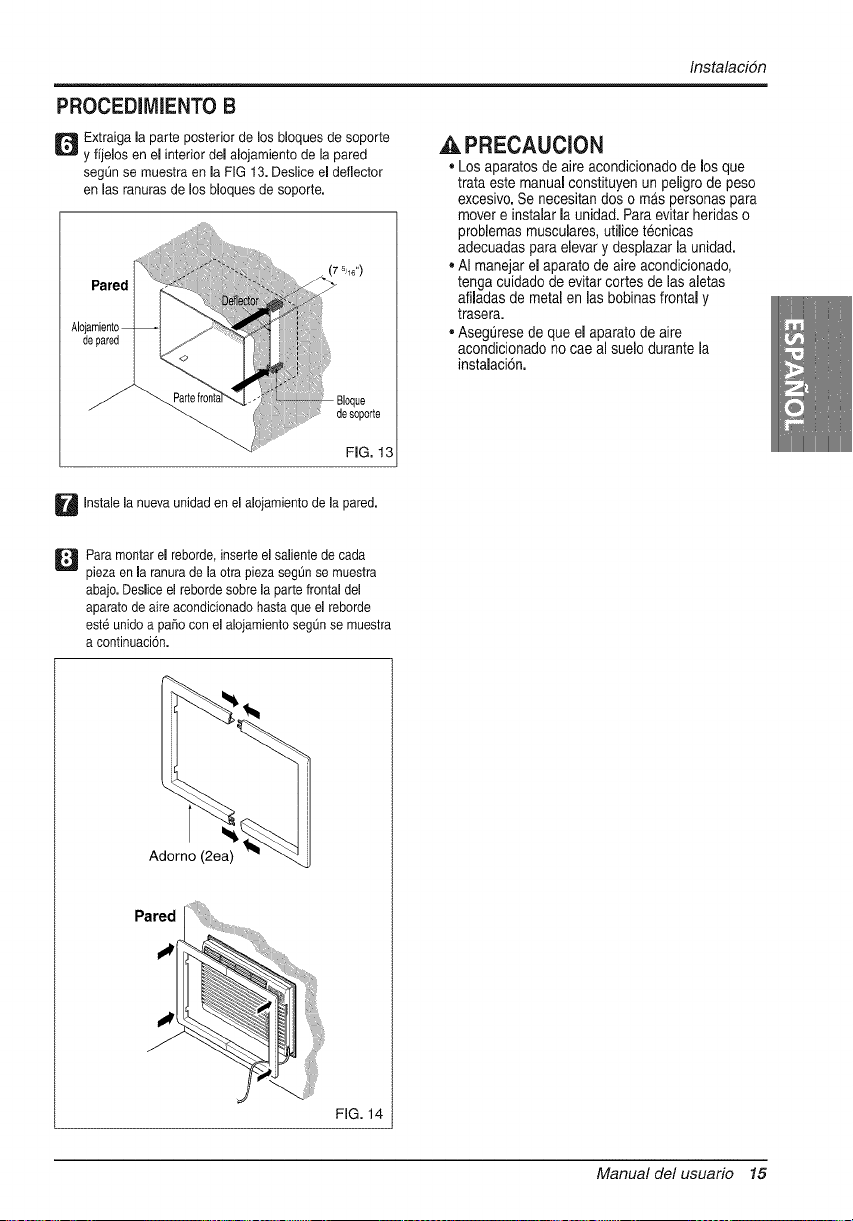
PROCEDIMIENTO B
_ Extraiga la parte posterior de los bloques de soporte ,_ PRECAUCION
y fijelos en el interior del alojamiento de la pared
seg_n se muestra en la FIG 13. Deslice el deflector • Los aparatos de aire acondicionado de los que
trata este manual constituyen un peligro de peso
en las ranuras de los Noques de soporte.
I
Alojal
de
desoporte
FIG. 13
excesivo.Se necesitan dos o mas personas para
mover e instalar la unidad. Para evitar heridas o
problemas musculares,utilice tecnicas
adecuadas para elevary desplazarla unidad.
AI manejar el aparato de aire acondicionado,
tenga cuidado de evitar cortes de las aletas
afiladas de metal en las bobinas frontal y
trasera.
Asegurese de que el aparato de aire
acondicionado no cae al suelo durante la
instalaci6n.
U Instalela nueva unidad en el alojamiento de la pared.
Q ara montar el reborde, inserte el saliente de cada
pieza en la ranura de la otra pieza seg[in se muestra
ebajo. Deslice el reborde sobre la parte frontal del
aparato de aire acondicionado hasta que el reborde
est6 unido a pai_o con el alojamiento segt_nse muestra
a continuaci6n.
A
Pared
FIG. 14
Manual del usuario 15
Instalacidn
PROCEDIMIENTO C
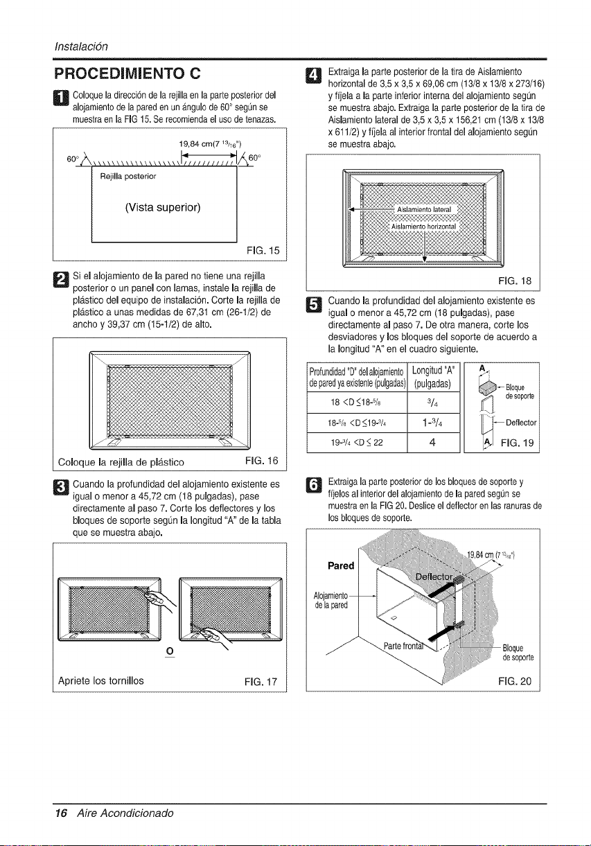
U oloque la direcciSnde la rejilla en la parte posterior del
alojamiento de la pareden un angulo de 60° segQnse
muestra en la FIG 15.Se recomienda el uso de tenazas.
19,84 cm(7 13h6")
60°_, ................... _/_ 60°
Rejilla posterior
(V sta super or)
FIG. 15
D i el alojamiento de la pared no tiene una rejilla
posterior o un panel con lamas, instale la rejilla de
pl_.stico del equipo de instalaci6n. Corte la rejilla de
plastico a unas medidae de 67,31 cm (26-1/2) de
ancho y 39,37 cm (15-1/2) de alto.
Coloque la rejilla de plb.stico
FIG. 16
_ uando la profundidad del alojamiento existente es
igual o menor a 45,72 cm (18 pulgadas), pase
directamente al paso 7. Corte los deflectores y los
bloques de soporte segOn la Iongitud "A" de la tabla
que se muestra abajo.
o
Apriete los tornillos FIG. 17
D xtraiga la parte posterior de la tira de Aislamiento
horizontal de 3,5 x 3,5 x 69,06 cm (13/8 x 13/8 x 273/16)
y fijela a la parte inferior interna del alojamiento seg_n
se muestra abajo. Extraiga la parte posterior de la tira de
Aislamiento lateral de 3,5 x 3,5 x 156,21 cm (13/8 x 13/8
x 611/2) y fijela al interior frontal del alojamiento seg_n
se muestra abajo.
FiG. 18
_ uando la profundidad del alojamiento existente es
igual o menor a 45,72 cm (18 pulgadas), pase
directamente al paso 7. De otra manera, corte los
desviadores y los bloques del soporte de acuerdo a
la Iongitud "A" en el cuadro siguiente.
Pr0fundidad"D"deHojamient0 Longitud"A"
deparedyaexistente(pulgadas](pulgadas)
18 <D_<18-% 3/4
t 8=5/8<D <19=s/4 t-3/4
19-3/4<D _<22 4
_ Bloque
desoporte
_ Deflector
A/I FIG. 19
Q xtraiga la parte posterior de los bloquesde soporte y
fijelos al interior del alojamiento de la pared segOnse
muestra en la FiG 20.Deslice el deflector en las ranurasde
los bloquesde soporte.
!
Alojar
dela
/
FIG. 20
16 Aire Acondicionado

Instalacidn
PROCEDiMIENTO C
U xtraiga el refuerzo de las tiras de reborde 33,02 (13) y
fijelas seg0n se muestra abajo en la HG 22. La parte
superior del reborde debe colocarse enfrente del
reborde en la base del alojamiento de la pared.
Para montar el reborde, inserte el saliente de cada
pieza en la ranura de la otra pieza seg0n se muestra
ebajo. Deslice el reborde sobre la parte frontal del
aparato de aire acondicionado hasta que el reborde
est6 unido a paso con el alojamiento seg_Jnse muestra
a continuacien.
1.,,oh' 'F'.,0h
FiG. 21
l e"l I 6"1
FiG. 22
D Instalela nuevaunidaden el alojamientode la pared.
Adorno (2ea)
Pared
"!
FiG. 23
,&PRECAUCION
• Los aparatos de aire acondicionado de los que
trata este manual constituyen un peligro de peso
excesivo. Se necesitan dos o mAs personas para
mover e instalar la unidad. Para evitar heddas o
problemas musculares, utilice tecnicas
adecuadas para elevar y desplazar la unidad.
• AI manejar el aparato de aire acondicionado,
tenga cuidado de evitar cortes de las aletas
afiladas de metal en las bobinas frontal y
trasera.
• AsegQrese de que el aparato de aire
acondicionado no cae al suelo durante la
instalacien.
Manual del usuario 17
Instruccionesoperativas
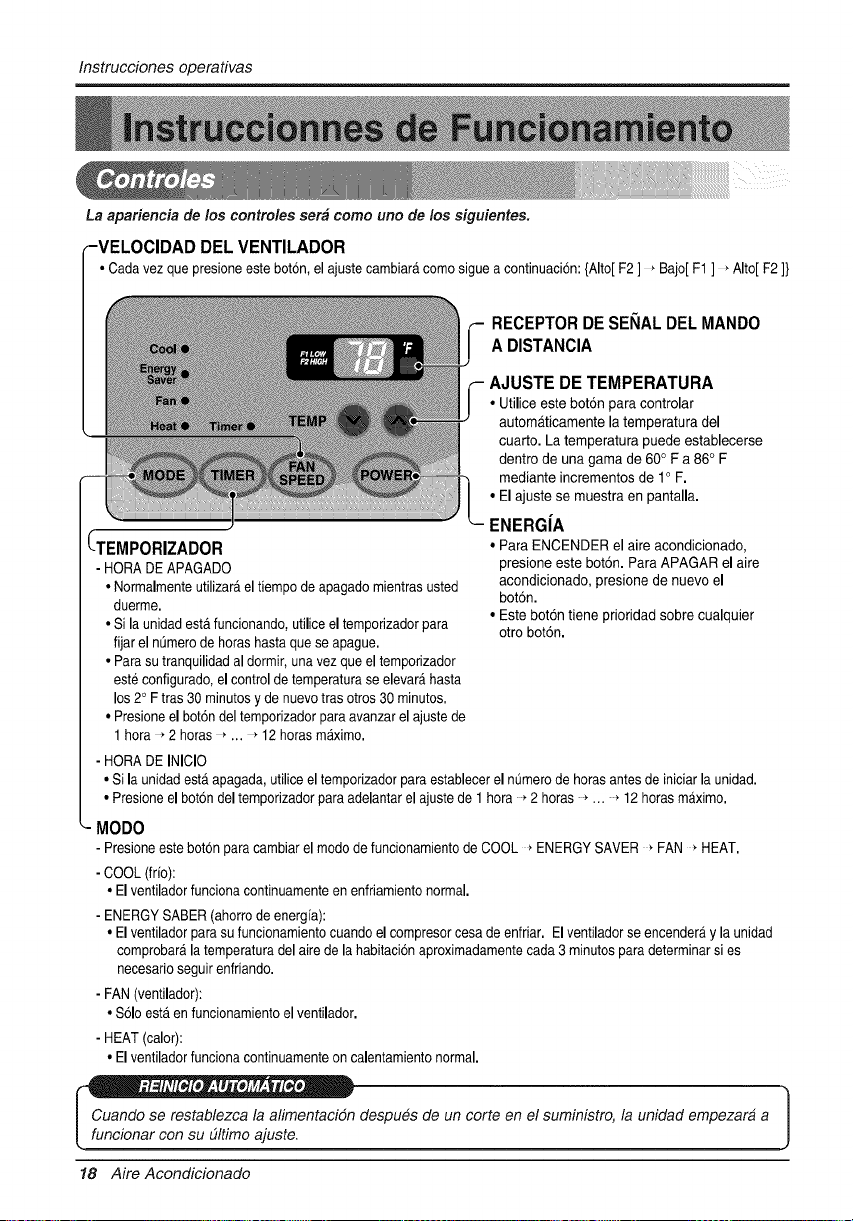
La apariencia de los controles serb como uno de los siguientes.
_VELOCIDAD DEL VENTILADOR
• Cadavezquepresioneestebot6n,elajustecambiar_,comosigueacontinuad6n:{Alto[F2] _Bajo[F1] _Alto[F2]}
RECEPTOR DE SENALDEL MANDO
A DISTANClA
(TEMPORIZADOR
- HORADE APAGADO
• Normalmenteutilizar_,el tiempo de apagadomientrasusted
duerme.
• Sila unidadest,.funcionando,utiliceel temporizadorpara
fijar el nSmerode horashastaque se apague.
• Parasu tranquilidadal dormir,una vezque el temporizador
est6 configurado,el controlde temperaturase elevar_,hasta
los20 Ftras 30 minutosy de nuevotras otros30 minutos.
• Presioneel bot6ndeltemporizadorpara avanzarel ajustede
1 hora , 2 horas _... _ 12horasm_.ximo.
- HORADE INICIO
AJUSTE DE TEMPERATURA
• Utilice estebot6n para controlar
automaticamente la temperatura del
cuarto. La temperatura puede establecerse
dentro de una gama de 60° F a 86° F
mediante incrementosde 1° F.
• El ajuste se muestraen pantalla.
ENERGiA
• Para ENCENDER el aire acondicionado,
presione este boton. Para APAGAR el aire
acondicionado, presione de nuevo el
boton.
• Este bot6n tiene prioridad sobre cualquier
otro bot6n.
• Si la unidadest,. apagada,utiliceel temporizadorparaestablecerel nOmerode horasantes de iniciarla unidad.
• Presioneel bot6ndel temporizadorpara adelantarel ajustede 1 hora 2 horas ... 12 horasmaximo.
_- MODO
- Presioneestebotonpara cambiarel modode funcionamientode COOL _ ENERGYSAVER _FAN _HEAT.
- COOL(frio):
• Elventiladorfuncionacontinuamenteen enfriamientonormal.
- ENERGYSABER(ahorrode energfa):
• Elventiladorparasufuncionamientocuandoel compresorcesade enfriar. Elventiladorseencender_y la unidad
comprobaralatemperaturadel aire de lahabitaci6naproximadamentecada3 minutosparadeterminarsi es
necesarioseguir enfriando.
- FAN(ventilador):
• Solo est,.en funcionamientoel ventilador.
- HEAT(calor):
• Elventiladorfuncionacontinuamenteon calentamientonormal.
_ despu6s de un corte en el suministro, la unidad empezara a
[ funcionar con su dltimo ajuste.
18 Aire Acondicionado
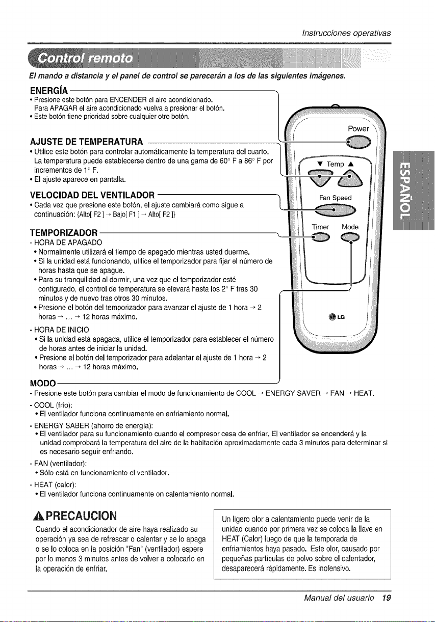
Instruccionesoperativas
El mando a distancia y el panel de control se parecer_n a los de las siguientes imagene&
ENERGiA
• Presioneeste bot6npara ENCENDERel aireacondicionado.
ParaAPAGARel aire acondicionadovuelvaa presionarel bot6n,
• Este bot6ntiene prioridadsobrecualquierotto botdn.
AJUSTE DE TEMPERATURA
• Utilice este botonpara controlar autornaticamente laternperatura del cuarto.
La temperatura puede establecerse dentro de una gama de 60° Fa 86° F por
incrementos de 1° F.
• Elajuste aparece en pantalla.
VELOCIDAD DEL VENTILADOR
• Cada vez que presione este bot6n, el ajuste cambiara como sigue a
continuaci6n:{Alto[F2] * Bajo[F1 ] >Alto[F2]}
TEMPORIZADOR
- HORA DE APAGADO
• Normalmente utilizar_,el tiempo de apagado mientras usted duerme.
• Si la unidad esta funcionando, utilice el temporizador para fijar el nt]mero de
horas hasta que se apague.
• Para sutranquilidad al dormir, una vez que el temporizador este
configurado, el controlde temperatura se elevar#,hasta los 2° F tras 30
minutos y de nuevo tras otros 30 minutos.
• Presioneel bot6n del temporizador para avanzar el ajuste de 1 hora >2
horas _ _. 4 12 horas m4ximo.
- HORA DE INICIO
• Si la unidad esta apagada, utilice el temporizador para establecer el nt3mero
de horasantes de iniciarla unidad.
• Presione el bot6n del temporizador para adelantar el ajuste de 1 hora _ 2
horas ... * 12 horas m_,ximo.
MODO
- Presione este bot6n para cambiar el modo de funcionamiento de COOL _ ENERGY SAVER _ FAN -_ HEAT.
- COOL (fifo):
• El ventilador funciona continuamente en enfriamiento normal,
- ENERGY SABER (ahorro de energfa):
• El ventilador para su funcionamiento cuando el compresor cesa de enfriar, El ventilador se encender_, y la
unidad comprobar_t la temperatura del aire de la habitaci6n aproximadamente cada 3 minutos para determinar si
es necesario seguir enfriando.
- FAN (ventilador):
• S61o est4 en funcionamiento el ventilador.
- HEAT (calor):
• El ventilador funciona continuamente on calentamiento normal,
APRECAUCION
Cuandoel acondicionadorde aire haya realizado su
operaci6n ya sea de refrescar o calentar y se Io apaga
o so Io coloca en la posici6n "Fan" (ventilador) espere
por Io menos 3 minutosantes de volver a colocarlo en
la operaci6n de enfriar.
Un ligero olor a calentamiento puedevenir de la
unidad cuando por primeravez se coloca la Ilave en
HEAT(Oalor) luegode que la temporadade
enfriamientos hayapasado. Este olor, causado por
peque_as partfculasde polvo sobre el calentador,
desaparecera rapidamente.Es inofensivo.
Manual del usuario 19
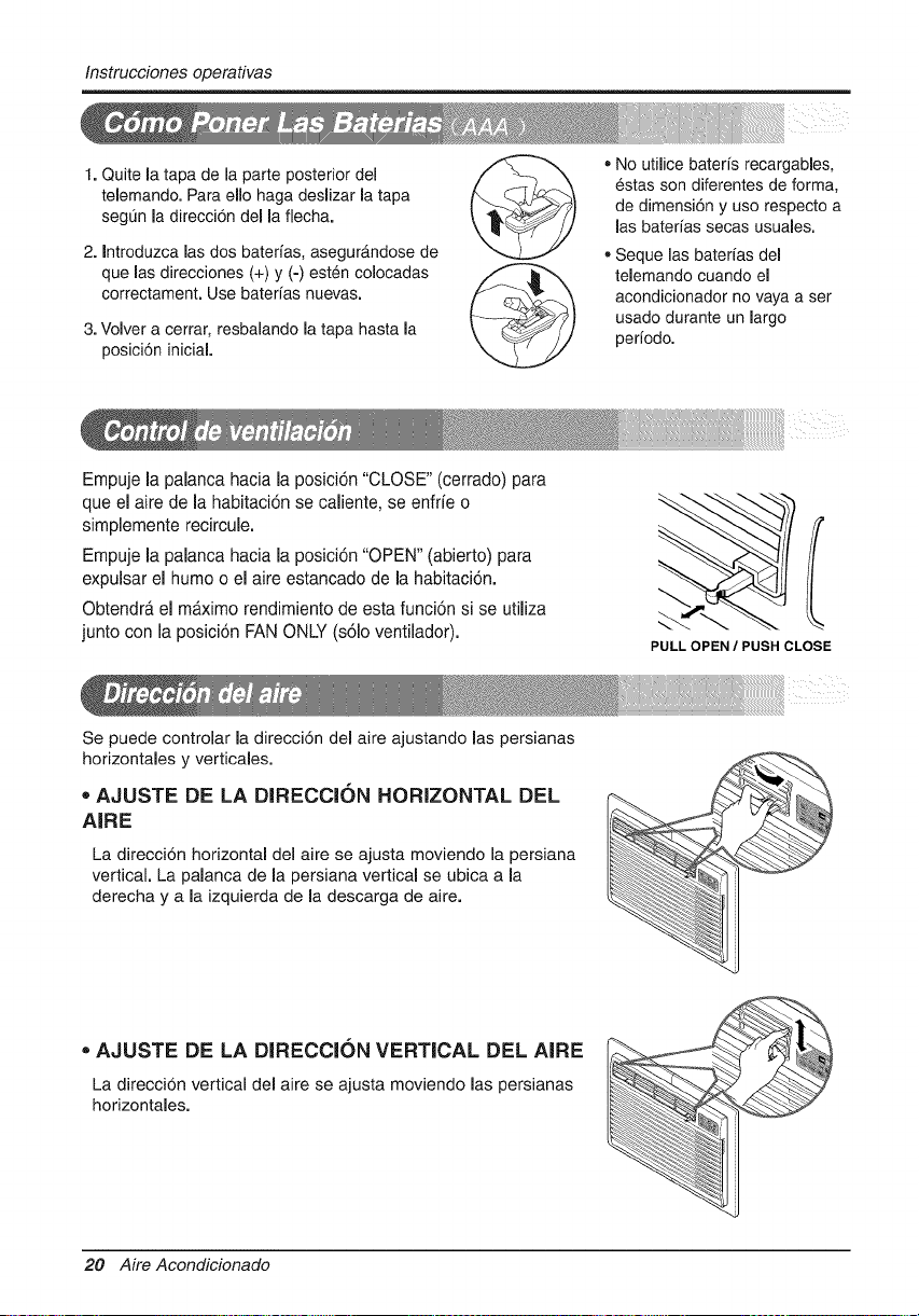
Instruccionesoperativas
1. Quite la tapa de la parte posterior del
telemando. Para ello haga deslizar la tapa
segL_nla direccidn della flecha.
2. Introduzca las dos batedas, asegur&ndose de
que las direcciones (+) y (-) esten colocadas
correctament. Use baterias nuevas.
3. Volver a cerrar, resbalando la tapa hasta la
posicidn iniciaL
, No utilice bateris recargables,
6stas son diferentes de forma,
de dimensi6n y uso respecto a
las baterias secas usuales.
o Seque las baterfas del
telemando cuando el
acondicionador no vaya a ser
usado durante un largo
periodo.
Empuje la palanca hacia la posici6n "CLOSE" (cerrado) para
que el aire de la habitaci6n se caliente, se enfrfe o
simplemente recircule.
Empuje la palanca hacia la posici6n "OPEN" (abierto) para
expulsar el humo o el aire estancado de la habitaci6n.
Obtendr#.el m_.ximo rendimiento de esta funci6n si se utiliza
junto con la posici6n FAN ONLY (s61oventilador).
PULL OPEN / PUSH CLOSE
Se puede controlar la direcci6n del aire ajustando las persianas
horizontales y verticales.
', AJUSTE DE LA DIRECCION HORIZONTAL DEL
AIRE
La direcci6n horizontal del aire se ajusta moviendo la persiana
vertical. La palanca de la persiana vertical se ubica a la
derecha y a la izquierda de la descarga de aire.
• AJUSTE DE LA DIRECCION VERTICAL DEL AIRE
La direcci6n vertical del aire se ajusta moviendo las persianas
horizontales.
20 Aire Acondicionado
CuidadoyMantenimiento
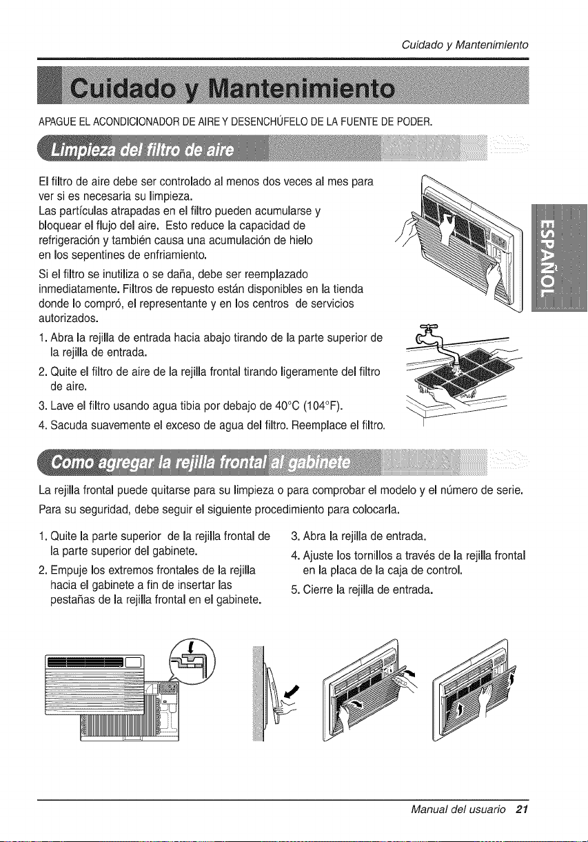
APAGUEEL ACONDICIONADORDE AIRE Y DESENCHOFELODE LA FUENTE DE PODER.
El filtro de aire debe ser controlado al menos dos veces al rues para
ver si es necesaria su limpieza.
Las particulas atrapadas en el filtro pueden acumularse y
bloquear el flujo del aire. Esto reduce la capacidad de
refrigeraci6n y tambien causa una acumulaci6n de hielo
en los sepentines de enfriamiento.
Si el filtro se inutilizao se da_a, debe ser reemplazado
inmediatamente. Filtros de repuesto estb,n disponibles en la tienda
donde Io compr6, el representante y en los centros de servicios
autorizados.
1. Abra la rejilla de entrada hacia abajo tirando de la parte superior de
la rejilla de entrada.
2. Quite el filtro de aire de la rejilla frontal tirando ligeramente del filtro
de aire.
3. Lave el filtro usando agua tibia per debajo de 40°C (104°F).
4. Sacuda suavemente el exceso de agua del filtro. Reemplace el filtro.
La rejilla frontal puede quitarse para su limpiezao para comprobar el modelo y el nQmerode serie.
Para su seguridad, debe seguir el siguiente procedimiento para colocarla.
1. Quite la parte superior de la rejilla frontal de
la parte superior del gabinete.
2. Empuje losextremos frontales de la rejilla
hacia el gabinete a fin de insertar las
pesta_as de la rejilla frontal en el gabinete.
3. Abra la rejilla de entrada.
4. Ajuste los tornillos a trav_s de la rejilla frontal
en la placa de la caja de control.
5. Cierre la rejilla de entrada.
! I
Manual del usuario 21
CuidadoyMantenimiento
, Puedequeescucheun ruidometalicocausadoporel aguarecogiday devueltahaciaelcondensadoren dias
lluviososo conakahumedad.EstacaracteristicadeldiseSoayudaa eliminarla humedady mejorarlaeficiencia.
, Puedequeescucheelchasquidodeltermostatocuandoelcompresorrealizaciclosdeencendidoy apagado.
, El aguaserecoger_,enla bandejade la baseendiasIluviososo conalta humedad.Puedequeel aguarebosey
caigadesdelaparteexteriorde la unidad.
, Puedequeelventiladorfuncioneaunqueel compresorno Iohaga.
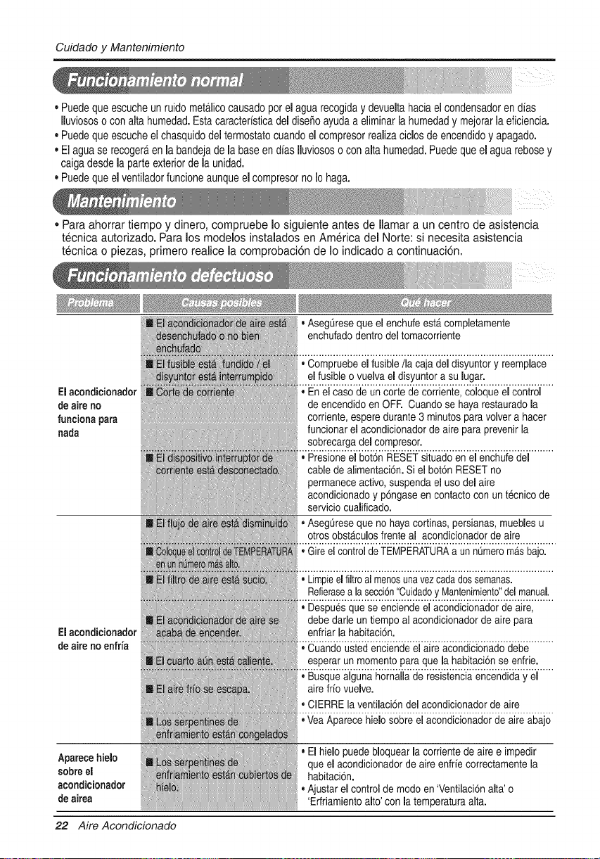
• Para ahorrar tiempo y dinero, compruebe Io siguiente antes de Ilamar a un centro de asistencia
tecnica autorizado. Para los modelos instalados en America del Norte: si necesita asistencia
tecnica o piezas, primero realice la comprobaci6n de Io indicado a continuaci6n.
El acondicionador
de aire no
funciona para
nada
Elacondicionador
deairenoenfria
Aparecehielo
sobreel
acondicionador
de airea
22 Aire Acondicionado
• Asegt_reseque el enchufe est,. completamente
enchufado dentro del tomacorriente
• Compruebe el fusible/la caja del disyuntor y reemplace
el fusible o vuelva el disyuntor a su lugar.
,, En el caso de un corte de corriente, coloque el control
de encendido en OFR Cuando se haya restauradola
corriente, espere durante 3 minutos paravolver a hacer
funcionar el acondicionadorde aire para prevenir la
sobrecarga del compresor.
• Presione el bot6n RESET situado en el enchufe del
cable de alimentaci6n. Si el bot6n RESET no
permanece activo,suspenda el uso del aire
acondicionadoy p6ngase en contacto con un t_cnico de
servicio cualificado.
• AsegQreseque no haya cortinas, persianas,muebles u
otros obst_.culosfrente al acondicionador de aire
• Gire el controlde TEMPERATURAa un nL_meroma.sbajo.
• Limpieel filtroal menosunavezcada dossemanas.
Refierasea lasecci6n"Cuidadoy Mantenimiento"delmanual.
• Despues que se enciende el acondicionador de aire,
debe dade un tiempo al acondidonador de aire para
enfriar la habitaci6n.
, Cuando usted enciende el aire acondicionado debe
esperar un momento paraque la habitaci6n se enfrie.
• Busque alguna hornalla de resistenciaencendida y el
aire fifo vuelve.
• ClERRE la ventilaci6n del acondicionador de aire
• VeaAparece hielo sobre el acondicionador de aire abajo
• El hielo puede bloquear la corriente de aire e impedir
que el acondicionador de aire enfrfe correctamente la
habitaci6n.
• Ajustar el control de modo en 'Ventilaci6nalta' o
'Erfriamiento alto' con la temperatura alta.
Nota
Manual del usuario 23
Nota
24 AireAcondicionado
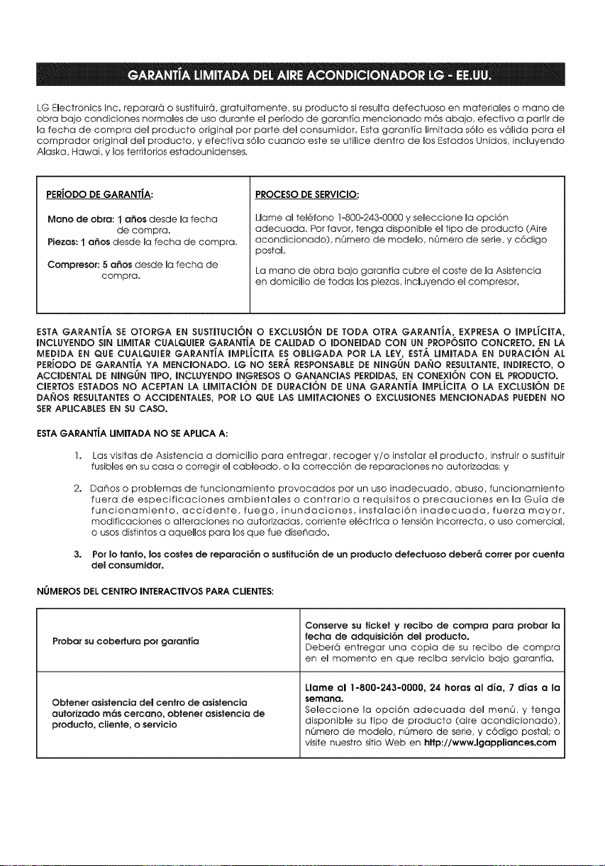
LG Electronics Inc. reparar6 o sustituir6, gratuitamente, su producto si resulta defectuoso en materiales o mano de
obra bajo condiciones normales de uso durante el perYodo de garantTa mencionado m6s abajo, efectivo a partir de
la techa de compra del producto original por parte del consumidor. Esta garanfia limitada s61o es v61ida para el
comprador original del producto, y efectiva s61o cuando este se utilice dentro de los Estados Unidos, incluyendo
Alaska, Hawai, y los territorios estadounidenses.
PERiODO DE GARANTiA:
Mano de obra: 1 a_os desde la fecha
de compra.
Piezas: 1 a6os desde la fecha de compra.
Compresor: 5 a6os desde la fecha de
compra.
PROCESO DE SERVICIO:
Llame al tel6fono 1-800-243-0000 y seleccione la opci6n
adecuada. Por favor, tenga disponible el tipo de producto (Aire
acondicionado), n(Jmero de modelo, nL_mero de serie, y c6digo
postal.
La mano de obra bajo garantia cubre el coste de la Asistencia
en domicilio de todas los piezas, incluyendo el compresor.
ESTA GARANTiA SE OTORGA EN SUSTITUCI6NO EXCLUSI6N DE TODA OTRA GARANTiA; EXPRESA O IMPLiCITA,
INCLUYENDO SIN LIMITAR CUALQUIER GARANTiA DE CALIDAD O mDONEIDAD CON UN PROPOSmTO CONCRETO. EN LA
MEDIDA EN QUE CUALQUIER GARANTiA IMPLiCITA ES OBLIGADA POR LA LEY, ESTA LIMITADA EN DURACI6N AL
PERIODO DE GARANTiA YA MENCIONADO. LG NO SERA RESPONSABLE DE NINGUN DAI_IO RESULTANTE, mNDIRECTO, O
ACCIDENTAL DE NINGON TIPO, INCLUYENDO INGRESOS O GANANCIAS PERDIDAS, EN CONEXI6N CON EL PRODUCTO.
CIERTOS ESTADOS NO ACEPTAN LA LIMITACI6N DE DURACI6N DE UNA GARANTiA IMPLiCITA O LA EXCLUSI6N DE
DAI_OS RESULTANTES 0 ACCmDENTALES, POR LO QUE LAS LIMITACIONES 0 EXCLUSIONES MENCIONADAS PUEDEN NO
SER APLICABLES EN SU CASO.
ESTAGARANTiA LIMITADA NO SEAPLICA A:
I.
2.
Los visitas de Asistencia a domicilio para entregar, recoger y/o instalar el producto, instruir o sustituir
fusibles en su casa o corregir el cableado, o la correcci6n de reparaciones no autorizadas; y
Dahos o problemas de funcionamiento provocados por un uso inadecuado, abuso, funcionamiento
fuera de especificaciones ambientales o contrario a requisitos o precauciones en la Guia de
funcionamiento, accidente,fuego, inundaciones, instalaci6n inadecuada,fuerza mayor,
modificaciones o alteraciones no autorizadas, corriente electrica o tensi6n incorrecta, o uso comercial,
o usos distintos a aquellos para los que rue diser_ado.
Por Io tanto, los costes de reparaci6n o sustituei6n de un producto clefectuoso deber6 correr pot cuenta
del consumidor.
NUMEROS DEL CENTRO INTERACTIVOS PARA CLIENTES:
Probar su cobertura por gorant_a
Obtener asistencia del centro de asistencia
autorizado m6s cercano, obtener asistencia de
producto, cliente, o servicio
Conserve su ticket y recibo de compra para probar la
fecha de adquisici6n del producto.
Deber6 entregar una copia de su recibo de compra
en el momento en que reciba servicio bajo garantia.
Llame al 1-800-243-0000, 24 horas al dla, 7 dias a la
semana.
Seleccione la opci6n adecuada del menLO, y tenga
disponible su tipo de producto (aire acondicionado),
n_mero de modelo, nL_mero de serie, y c6digo postal; o
visite nuestro sitio Web en http://www.lgappliances.com
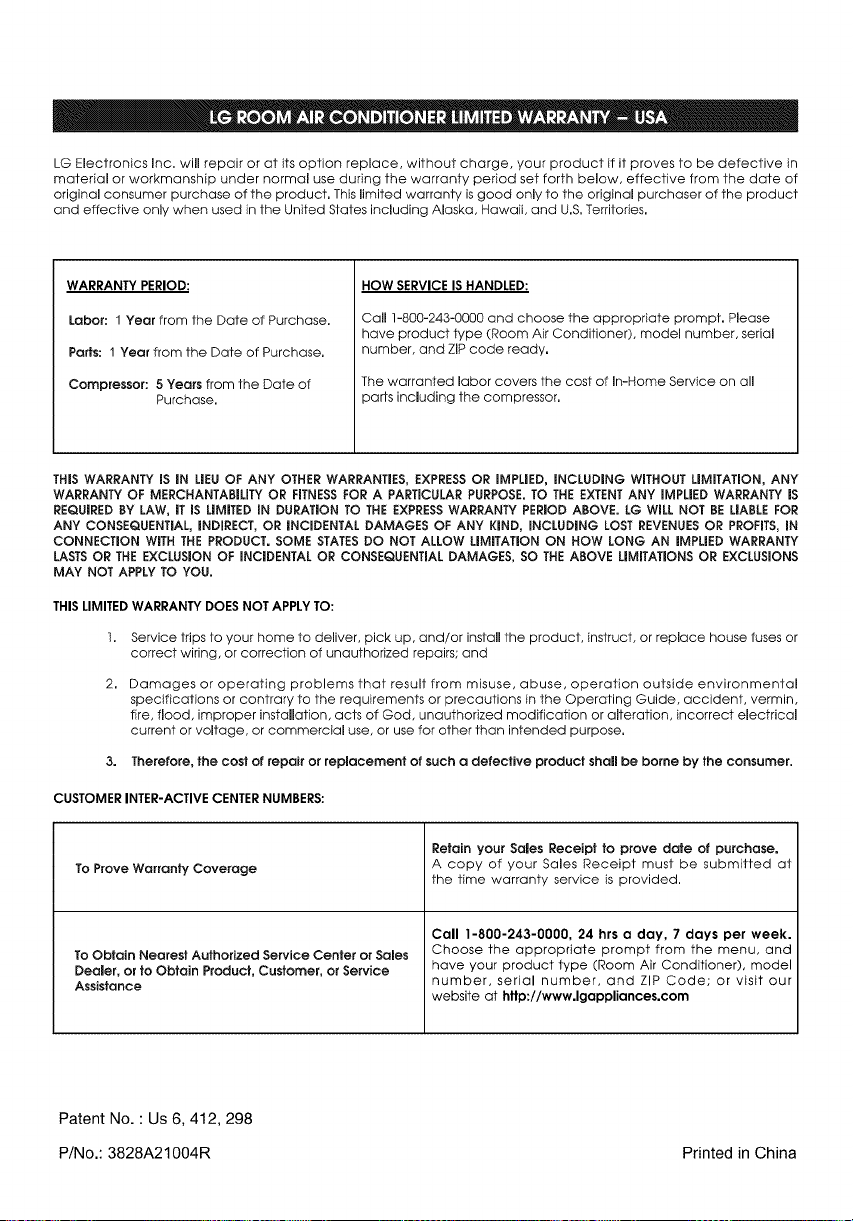
LG Electronics Inc. will repair or at its option replace, without charge, your product if it proves to be defective in
material or workmanship under normal use during the warranty period set forth below, effective from the date of
original consumer purchase of the product. This limited warranty is good only to the original purchaser of the product
and effective only when used in the United States including Alaska, Hawaii, and U.S.Territories.
WARRANTY PERIOD:
Labor: 1 Year from the Date of Purchase.
Paris: 1 Year from the Date of Purchase.
Compressor: 8 Years from the Date of
Purchase.
HOW SERVICEIS HANDLED:
Call 1-800-243-0000 and choose the appropriate prompt. Please
have product type (Room Air Conditioner), model number, serial
number, and ZiP code ready.
The warranted labor covers the cost of In-Home Service on all
)arts including the compressor.
THiS WARRANTY iS mNLiEU OF ANY OTHER WARRANTIES, EXPRESSOR IMPLIED, INCLUDmNG WITHOUT LIMITATION, ANY
WARRANTY OF MERCHANTABILITY OR FITNESSFOR A PARTICULAR PURPOSE. TO THE EXTENTANY mMPLIEDWARRANTY iS
REQUIRED BY LAW, iT IS LiMiTED IN DURATION TO THE EXPRESSWARRANTY PERIOD ABOVE. LG WILL NOT BE LIABLEFOR
ANY CONSEQUENTIAL, iNDIRECT, OR iNCIDENTAL DAMAGES OF ANY KIND, INCLUDING LOST REVENUES OR PROFITS,IN
CONNECTION WITH THE PRODUCT. SOME STATESDO NOT ALLOW LIMiTATiON ON HOW LONG AN iMPLiED WARRANTY
LASTS OR THE EXCLUSION OF INCIDENTAL OR CONSEQUENTIAL DAMAGES, SO THE ABOVE LiMiTATiONS OR EXCLUSIONS
MAY NOT APPLY TO YOU.
THIS LIMITEDWARRANTY DOES NOT APPLY TO:
1. Service trips to your home to deliver, pick up, and/or install the product, instruct, or replace house fuses or
correct wiring, or correction of unauthorized repairs; and
2. Damages or operating problems that result from misuse, abuse, operation outside environmental
specifications or contrary to the requirements or precautions in the Operating Guide, accident, vermin,
fire, flood, improper installation, acts of God, unauthorized modification or alteration, incorrect electrical
current or voltage, or commercial use, or use for other than intended purpose.
3. Therefore, the cost of repair or replacement of such a defective product shall be borne by the consumer.
CUSTOMER INTER-ACTIVE CENTERNUMBERS:
To Prove Warranly Coverage
To Obtain Nearest Authorized Service Center or Sales
Dealer, or to Obtain Product, Customer, or Service
Assistance
Retain your Sales Receipt to prove date of purchase.
A copy of your Sales Receipt must be submitted at
the time warranty service is provided.
Call 1-800-243-0000, 24 hrs a day, 7 days per week.
Choose the appropriate prompt from the menu, and
have your product type (Room Air Conditioner), model
number, serial number, and ZIP Code; or visit our
website at http://www.lgappliances.com
Patent No. : Us 6, 412, 298
P/No.: 3828A21004R Printed in China

