Installation
ON
OFF
ON
OFF
ON
OFF
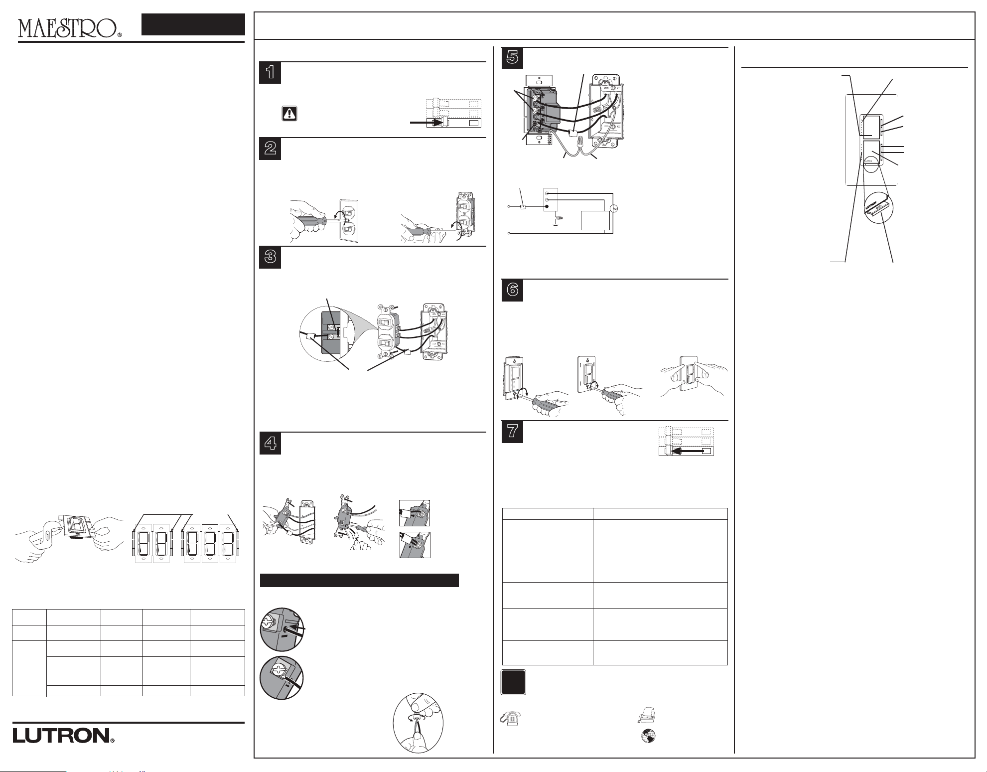
Turning Power OFF.
• Turn power OFF at circuit breaker (or remove fuse).
1
Removing Wallplate and Switch.
• Remove the wallplate and switch mounting screws.
• Carefully remove switch from wall (do not remove wires).
2
Verifying Application.
3
Wiring the Control.
5
Mounting Control(s) to Wallbox.
• Form wires carefully into wallbox, mount and align control(s).
• Install the wallplate(s).
6
ON
OFF
ON
OFF
ON
OFF
Turning Power ON.
• Turn power ON at circuit breaker
(or replace fuse).
7
030-1407
030-1407
English
Turn screws to loosen.
For new construction, go to step 5.
Lutron
Technical Support Center 1.800.523.9466 24 hrs / 7 days www.lutron.com
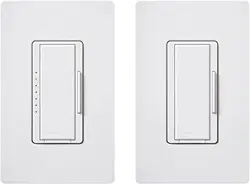
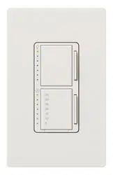
Dual Incandescent Dimmer/Timer
MA-L3T251
Rated at 120 V~ 60 Hz 300 W Incandescent load and 2.5 A Timer load.
Important Notes
Please read before installing.
1. Only use dimmer with permanently installed incandescent or 120 V~
halogen fixtures. To avoid overheating and possible damage to other
equipment, do not use to control receptacles, fluorescent lighting
fixtures, low-voltage lighting fixtures, motor-driven appliances, or
transformer-supplied appliances.
2. Use timer switch to control any permanently installed lighting or fan load.
Check power requirements for all attached heating devices as they may
max exceed the power limits shown in the capacity chart.
3. Install in accordance with all national and local electrical codes.
4. DO NOT install compact fluorescent (Energy Saver) lamps in the dimmer
circuit, these lamps may only be installed in the timer circuit.
5. Dimmer and timer require separate wires in the wallbox for each load.
6. Do not use for loads operated from two or more locations (3-Way or
4-Way).
7. When no “grounding means” exist within the wallbox then the NEC
®
2008,
Article 404.9 allows a control without a grounding connection to be
installed as a replacement, as long as a plastic, noncombustible wallplate
is used. For this type of installation, cap or remove the green ground wire
on the control and use an appropriate wallplate such as Claro
®
or Satin
Colors® series wallplates by Lutron®.
8. For new installations, install a test switch before installing the control.
9. Protect control from dust and dirt when painting or spackling.
10. Unit will not operate with less than 40 W of load installed on dimmer.
11. It is normal for the control to feel warm to the touch during operation.
12. Clean control with a soft damp cloth only. Do not use any chemical
cleaners.
13. Operate between 32 °F (0 °C) and 104 °F (40 °C)
14. Recommended wallbox depth is 2.5 in (64 mm) minimum.
Multigang Installation
When combining controls in a wallbox, remove all inner side sections before wiring (see
below). Use pliers to bend each side section up and down until it breaks off. Repeat for
each side section to be removed. Reduction of control capacity is also required. Refer to
chart below for maximum capacity.
?
Technical Assistance
If you have questions concerning the installation or operation
of this product, call the Lutron Technical Support Center.
Please provide exact model number when calling.
U.S.A. and Canada (24 hrs/7days)
1.800.523.9466
Other countries (8am – 8pm ET)
+1.610.282.3800
México
+1.888.235.2910
Fax +1.610.282.1243
http://www.lutron.com
• This control mounts in a single-gang wallbox and controls
two loads independently. Independent wires must be
provided for each load.
• Tag the wire that is connected to the feed side of the switch (the side with the
breakoff fin).
• If connecting a fan, fluorescent, low-voltage or other non-incandescent/halogen load,
note which switch and corresponding screw terminal controls it and mark this wire
to be installed on the timed channel in step 5. Failure to do so may damage the load
and control.
Identify Side with
Break-off fin
Tag
• Connect the tagged wire
removed from the feed side
of the switch to the black
screw terminal on the Control
labeled Live.
• Connect one of the remaining
wires controlling an
incandescent/halogen load to
the top brass terminal
labeled Dimmer.
• Connect the remaining wire
removed from the switch to
the remaining brass screw
terminal on the Control
labeled Timer.
• Use wire connectors to
connect the green ground
wire on the Control to the
bare copper or green
ground wire in the wallbox,
and to cap any unused
wires. See wire connector
bag for installation
instructions.
Brass
screws
Black
screw
Green
Wire
Tag
Ground
Wire
Brass
Brass
Live
Black
Neutral
Tag
Ground
Light
120 V~
60 Hz
Dimmer
Timer Switch
Limited Warranty
(Valid only in U.S.A., Canada, Puerto Rico, and the Caribbean.)
Lutron will, at its option, repair or replace any unit that is defective in materials or manufacture
within one year after purchase. For warranty service, return unit to place of purchase or mail to
Lutron at 7200 Suter Rd., Coopersburg, PA 18036-1299, postage pre-paid.
THIS WARRANTY IS IN LIEU OF ALL OTHER EXPRESS WARRANTIES, AND THE
IMPLIED WARRANTY OF MERCHANTABILITY IS LIMITED TO ONE YEAR FROM
PURCHASE. THIS WARRANTY DOES NOT COVER THE COST OF INSTALLATION,
REMOVAL OR REINSTALLATION, OR DAMAGE RESULTING FROM MISUSE, ABUSE, OR
DAMAGE FROM IMPROPER WIRING OR INSTALLATION. THIS WARRANTY DOES NOT
COVER INCIDENTAL OR CONSEQUENTIAL DAMAGES. LUTRON’S LIABILITY ON ANY
CLAIM FOR DAMAGES ARISING OUT OF OR IN CONNECTION WITH THE
MANUFACTURE, SALE, INSTALLATION, DELIVERY, OR USE OF THE UNIT SHALL
NEVER EXCEED THE PURCHASE PRICE OF THE UNIT.
This warranty gives you specific legal rights, and you may have other rights which vary from state to
state. Some states do not allow the exclusion or limitation of incidental or consequential damages,
or limitation on how long an implied warranty may last, so the above limitations may not apply to you.
Lutron, Claro, Maestro, and Satin Colors are registered trademarks
and FASS is a trademark of Lutron Electronics Co., Inc.
NEC is a registered trademark of
National Fire Protection Association, Quincy, Massachusetts.
© 2010 Lutron Electronics Co., Inc.
Important Wiring Information
Trim or strip wallbox wires to the length indicated by the strip gauge on
the back of the control.
Push-in Terminals: Insert wires fully.
Note: Push-in terminals are for use with 14 AWG
(1.5 mm
2
) solid copper wire only. DO NOT use stranded
or twisted wire.
Screw Terminals: Tighten securely.
Screw terminals are for use with 12 AWG (2.5 mm
2
) or
14 AWG (1.5 mm
2
) solid copper wire only. DO NOT use
stranded or twisted wire.
Or
Lutron Electronics Co., Inc.
7200 Suter Road
Coopersburg, PA 18036-1299, U.S.A.
Made and printed in the U.S.A.
11/10 P/N 030-1407 Rev. A
Troubleshooting
Symptoms
Light does not work or no LEDs
turn on.
Top and bottom switches
control wrong loads.
Dimmer and Timer behave
erratically.
Tap switch does not work at
brightest level.
Possible Causes
• Light bulbs burned out.
• Breaker is OFF or tripped.
• Dimmer channel not connected to load.
• Front Accessible Service Switch (FASS
TM) on
Control is pulled out to the off position.
• Wiring error. Call Lutron Technical Support
Center at 1.800.523.9466.
• Wires going to the two brass screws are
reversed.
• Live wire is connected to the dimmer screw. Fix
wiring error to ensure FASS removes power to
both loads.
• Dimmer load is less than 40 W.
Wire Connector:
Use to join one 14 AWG (1.5 mm
2
) or 12 AWG
(2.5 mm
2
) ground wire with one 18 AWG
(0.75 mm
2
) control ground wire.
Twist wire
connector
tight.
Breaking Side Sections
Do Not Remove
Outside Sections
Each Control Has Inside
Section Removed
Middle Control Has Two
Side Sections Removed
Note: This control is rated for fan and lighting loads only.
Light or Fan
Fixture(s)
Dimmer/Timer Capacity Chart
Channel
Dimmer
Timer
Load
Incandescent
120 V~ Halogen
No Sides
Removed
300 W
1 Side
Removed
250 W
2 Sides
Removed
200 W
General Purpose Fan
Incandescent
120 V~ Halogen
Electronic Low-Voltage
Fluorescent
Magnetic Low-Voltage*
2.5 A
300 W
300 VA / 250 W*
2.0 A
250 W
250 VA / 200 W*
1.5 A
200 W
200 VA / 150 W*
4
Disconnecting Switch Wires.
Important Note: Your wall switch may have two wires attached
to the same screw (see illustrations below for examples). Tape
these two wires together before disconnecting. When wiring,
connect wires to the Timer the same way they were connected
to the switch.
Screw Terminals:
Turn screws to loosen.
Push-in Terminals:
Insert screwdriver.
Pull wire out.
One wire in the push-
in terminal and one to
the screw.
One continuous wire
to the screw.
Note: Do not overtighten mounting screws.
Snap on Claro
wallplate.
Start screws.
Align control and
tighten screws.
To verify the control is correctly wired, test to make sure that the dimmer and switch are working
properly on the correct load. If any unexpected behavior occurs, check the troubleshooting guide.
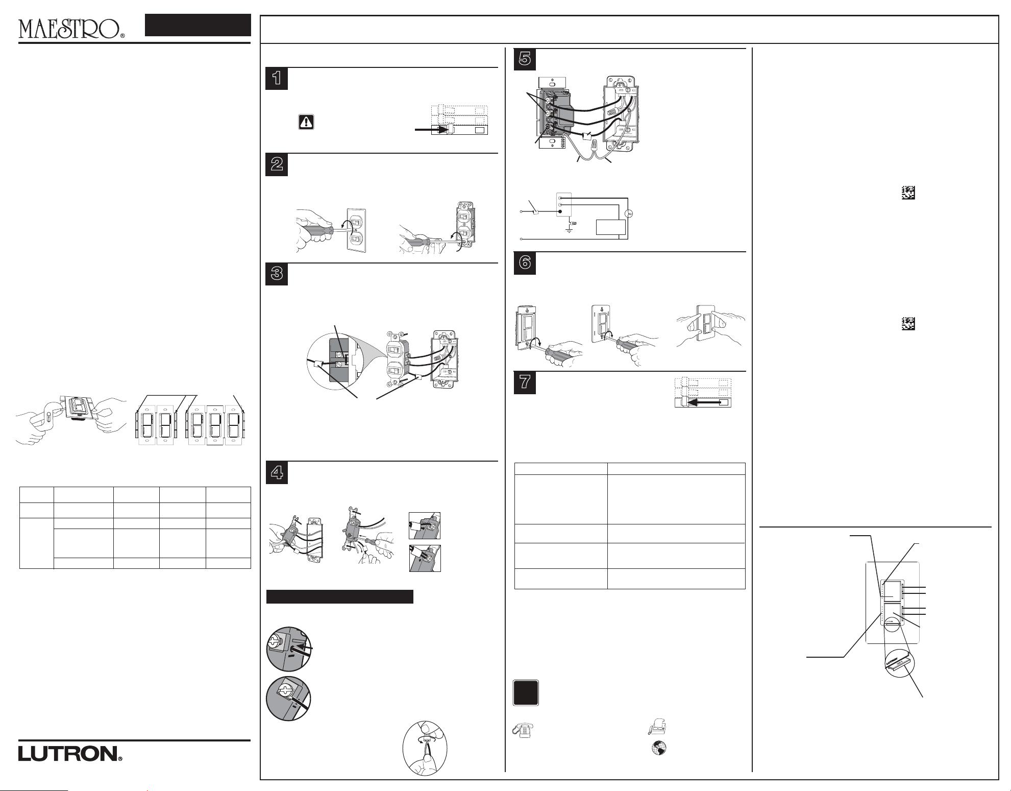
Operation
Light Level Tap Buttons
• Tap once when lights are off -
Lights brighten smoothly to preset
intensity.
• Tap once when lights are on -
Lights dim smoothly to off.
• Tap twice quickly - Lights brighten
rapidly to full intensity.
• Press and hold when lights are on -
Activates delayed fade to off mode.
As the tap button is held, the LEDs
will begin to flash. The first flashing
LED represents a 10 second fade to
off. Each additional flashing LED
represents an additional 10 seconds
of delay before lights fade off (up to
60 seconds delay).
Light Level LEDs
• Indicates approximate
light level.
LEDs may not change
with each press.
FASS
T
TM - Front Accessible
Servie Switch
Important Note:
To replace a bulb, remove power by pulling the
FASS switch out on the Control. For any
procedure other than routine bulb
replacement, power must be disconnected at
the main electrical panel.
To learn about the Advanced Features of Maestro
®
Dimmers including locked preset and
adjustable fade times, please visit:
www.lutron.com/maestro/advfeatures or call the
Lutron Technical Support Center at 1.800.523.9466.
Timer Tap Button
• Tap once when unit is OFF
- Controlled load turns ON and
countdown timer begins.When
time expires, load turns OFF.
• Tap once when unit is on -
Controlled load turns off.
• Tap twice quickly
- Controlled load turns on without
a time limit.
Press to increase light level.
Press to decrease light level.
Press to increase time.
Press to decrease time.
Timer LEDs
• Orange LEDs indicate timer duration or
remaining time in minutes.
• Top green LED labeled On has no time
limit.
• Bottom LED blinks rapidly to indicate
one minute of time remaining.
One Minute Indication:
When only one minute of time is
remaining, the load will briefly turn off
and on to give an indication the timer is
about to turn off.
* The maximum lamp wattage is determined by the efficiency of the transformer, with 70%–85% as typical.
For actual transformer efficiency, contact either the fixture or transformer manufacturer. The total VA rating
of the transformer(s) shall not exceed the VA rating of the timer.
WARNING: Before proceeding, verify that
power to the switch is OFF.
Otherwise, death or serious injury
could result.
Cobre
Cobre
Vivo
Negro
Neutro
Instalación
ON
OFF
ON
OFF
ON
OFF
Apagado.
• Desconecte la alimentación en el cortacircuito (o quite el fusible).
1
Remoción de la placa de pared
y el interruptor.
• Retire la placa de pared y los tornillos de montaje del interruptor.
•
Retire el interruptor de la pared con cuidado (no saque los
cables).
2
Verifique la aplicación.
3
Cableado del Control.
5
Montaje del Control(es) en la
caja de embutir.
• Coloque los cables cuidadosamente en la caja de embutir,
monte y alinee el control(es).
• Instale la(s) placa(s) de pared.
6
ON
OFF
ON
OFF
ON
OFF
Encendido.
• Encienda el interruptor de circuito
(o reemplace el fusible).
7
Espa
ñol
Operación
Afloje los tornillos.
Centro de Soporte Técnico de
Lutron
1.888.235.2910 24 horas / 7 días www.lutron.com
Atenuador Incandescente /
Temporizador Doble
MA-L3T251
Valor nominal 120 V~ 60 Hz
Carga Incandescente de 300 W y carga de Temporizador de 2,5 A
Notas Importantes
Por favor lea antes de instalar.
1. Utilice el atenuador únicamente con artefactos incandescentes o
halógenos de 120 V~ de instalación permanente. Para evitar el
recalentamiento y el posible daño a otro equipo, no lo utilice para
controlar receptáculos, artefactos de iluminación fluorescente,
artefactos de iluminación de bajo voltaje, dispositivos a motor o
alimentados por un transformador.
2. Utilice el interruptor temporizador para controlar cualquier carga de
ventilador o iluminación de instalación permanente. Verifique los requisitos
de alimentación para los dispositivos de calentamiento conectados dado
que pueden exceder los límites máximos de potencia que se muestran en
la tabla de capacidad.
3. La instalación se debe realizar de acuerdo con todas las reglamentaciones
de los códigos eléctricos nacionales y locales.
4. NO instale lámparas fluorescentes compactas (que Ahorran Energía) en el
circuito del atenuador, estas lámparas sólo pueden ser instaladas en el
circuito del temporizador.
5. El atenuador y el temporizador requieren cables separados en la caja de
embutir para cada carga.
6. No los utilice para cargas operadas desde dos o más ubicaciones
(3 posiciones o 4 posiciones).
7. Si en la caja de embutir no hay accesso a una conexión de tierra, la norma
NEC® 2008, Article 404.9 permite instalar como reemplazo un control sin
conexión a tierra, en tanto se utilice una placa de pared de plástico no
combustible. Para este tipo de instalación, aisle o elimine el conductor
verde de tierra del control y utilice una placa adecuada tal como la Claro
TM
o Satin ColorsTM de Lutron®.
8. Para instalaciones nuevas, instale un interruptor de prueba antes de
instalar el control.
9. Proteja el control del polvo y la suciedad al pintar o revocar.
10. La unidad no funcionará con una carga menor 40 W instalada en el
atenuador.
11. Es normal que el control se sienta caliente al tacto durante su
funcionamiento.
12. Limpie el control con un trapo húmedo suave solamente. No utilice
limpiadores químicos.
13. Mantenga entre los 0 °C (32 °F) y los 40 °C (104 °F) de temperatura.
14. La profundidad de caja recomendada es de 64 mm (2,5 pi) mínimo.
Instalación para dispositivos múltiples
Al combinar controles en una caja de embutir, retire las secciones laterales interiores antes
de cablear (vea más abajo). Utilice pinzas para doblar cada sección lateral hacia arriba y
hacia abajo hasta que se quiebren. Repita el procedimiento en cada sección lateral a ser
removida. También se exige la reducción de la capacidad del control. Consulte la tabla
debajo para obtener información de las capacidades máximas.
?
Asistencia Técnica
Si usted tiene alguna duda con respecto a la instalación o al
funcionamiento de este producto, comuníquese con el Centro
de Soporte Técnico de Lutron. Por favor, indique el modelo
exacto al llamar.
E.U.A y Canadá (24 horas/7 días)
1.800.523.9466
Otros países (8am – 8pm Hora del Este)
+1.610.282.3800
México
+1.888.235.2910
Fax +1.610.282.1243
http://www.lutron.com
En construcciones nuevas vaya al paso 5.
•
Este control se monta en una caja de embutir con un único
dispositivo y controla dos cargas independientemente. Los
cables independientes deben ser suministrados para cada carga.
• Etiquete el cable que es conectado del lado de alimentación del interruptor (el lado
con la aleta de quiebre).
• Si desea conectar un ventilador, una carga fluorescente, de bajo voltaje u otra no
incandescente/halógena, fíjese qué interruptor y borne de tornillo correspondiente la
controla y marque este cable para ser instalado en el canal de temporizador en el
paso 5. En el caso de no hacerlo, se podría dañar la carga y el control.
Identifique el Lateral con la aleta de Quiebre
Identificación
• Conecte el cable rotulado
que se retiró del lado de la
alimentación del interruptor al
borne negro del tornillo en el
Control etiquetado como
Vivo.
• Conecte uno de los cables
restantes que controla una
carga
incandescente/halógena al
borne de cobre superior
rotulado Atenuador.
• Conecte el cable restante
extraído del interruptor al otro
borne de tornillo de cobre
del Control rotulado
Temporizador.
• Use conectores de cables
para conectar el cable a tierra
verde del Control al cable de
cobre o cable a tierra verde
de la caja de embutir, y para
tapar los cables que no han
sido utilizados. Vea la bolsa
del conector de cables para
obtener las instrucciones de
instalación.
Tornillos
de
cobre
Tornillo
negro
Cable Verde
Identificación
Cable de
Tierra
Identificación
Tierra
Luz
120 V~
60 Hz
Atenuador
Temporizador
Botones de Nivel de Luz
• Presione una vez cuando las luces
se encuentren apagadas -
Las luces aumentarán su intensidad
suavemente hasta alcanzar el nivel
prefijado.
• Presione una vez cuando las luces
estén encendidas -
Las luces se irán atenuando hasta
Apagarse.
• Presione dos veces rápidamente -
Las luces iluminarán rápidamente
hasta alcanzar la intensidad máxima.
• Oprima y sostenga cuando las
luces estén encendidas - Se activa
el modo de desvanecimiento gradual
hasta apagar con retardo. Cuando
tenga presionado el botón para
encender y apagar, los indicadores
LED comenzarán a parpadear. El
primer indicador LED que parpadea
representa 10 segundos de
desvanecimiento hasta apagar. Cada
uno de los otros indicadores LED
parpadeantes representa
10 segundos más antes de que las
luces se desvanezcan hasta apagarse
(hasta 60 segundos de demora).
LEDs de Niveles de Luz
• Indica el nivel de luz
aproximado
Es posible que los LED no
cambien con cada presión.
FASSTM– Interruptor de Servicio
Accesible por el Frente
Aviso Importante:
Para reemplazar una bombilla,quite la alimentación tirando
del interruptor
FASS
hacia fuera en el Control.Para otro
procedimiento que no sea el reemplazo rutinario de bombillas,
la alimentación debe ser desconectada desde el panel
eléctrico principal.
Para obtener información acerca de las Características Avanzadas de los Atenuadores Maestro
®
incluyendo la
preprogramación bloqueada y los tiempos ajustables de desvanecimiento, por favor visite:
www.lutron.com/maestro/advfeatures o llame al Centro de Soporte Técnico
Lutron
al 1.800.523.9466.
Botón Temporizador
• Dé un golpecito cuando la
unidad esté Apagada - La
carga controlada se ENCIENDE y el
reloj de cuenta regresiva
comienza. Cuando el tiempo
expira, la carga se Apaga.
• Dé un golpecito cuando la
unidad esté Encendida - La
carga controlada se Apaga.
• Golpee dos veces
rápidamente
- La carga controlada se Enciende
sin límite de tiempo.
Garantía Limitada
(Válido solamente en los E.U.A., Canadá, Puerto Rico, y el Caribe.)
Lutron, a discreción propia, reparará o reemplazará las unidades con fallas en sus
materiales o fabricación dentro del año posterior a la compra de las mismas. Para obtener
el servicio de garantía, remita la unidad al lugar donde la adquirió o envíela a Lutron, 7200
Suter Rd., Coopersburg, PA 18036-1299, con servicio postal prepago.
ESTA GARANTÍA REEMPLAZA A TODA OTRA GARANTÍA EXPRESA Y LA
GARANTÍA IMPLÍCITA DE COMERCIABILIDAD ESTÁ LIMITADA A UN AÑO DESDE
LA FECHA DE COMPRA. ESTA GARANTÍA NO CUBRE EL COSTO DE
INSTALACIÓN, DE REMOCIÓN NI DE REINSTALACIÓN, NI LOS DAÑOS
PROVOCADOS POR USO INCORRECTO O ABUSO NI LOS DAÑOS RESULTANTES
DE UN CABLEADO O UNA INSTALACIÓN INCORRECTOS. ESTA GARANTÍA NO
CUBRE DAÑOS INCIDENTALES O INDIRECTOS. LA RESPONSABILIDAD DE
LUTRON ANTE UNA DEMANDA POR DAÑOS CAUSADOS POR O RELACIONADOS
CON LA FABRICACIÓN, VENTA, INSTALACIÓN, ENTREGA O USO DE LA UNIDAD
NO EXCEDERÁ EN NINGÚN CASO EL PRECIO DE COMPRA DE LA UNIDAD.
La presente garantía le otorga derechos legales específicos y usted puede tener otros derechos
que varían según el estado. Algunos estados no admiten la exclusión o limitación de los daños
incidentales o indirectos, ni las limitaciones en la duración de las garantías implícitas, de modo que
las
limitaciones anteriores pueden no ser aplicables en su caso.
Lutron es una marca registrada,
y FASS, Claro, Maestro, y Satin Colors son marcas de Lutron Electronics Co., Inc.
NEC es una
marca registrada de National Fire Protection Association, Quincy, Massachusetts.
© 2010 Lutron Electronics Co., Inc.
Información Importante sobre Cableado
Recorte o pele los cables de la caja de embutir hasta la medida
indicada en el reverso del control.
Borneras a presión: Inserte los cables completamente.
Nota: Las borneras a presión se utilizan únicamente
con cables de cobre sólido de 1,5 mm
2
(14 AWG). NO
utilice cable trenzado ni retorcido.
Bornes de Tornillo: Ajuste con firmeza.
Los bornes de tornillo se deben usar sólo con cables de
cobre sólido de 2,5 mm
2
(12 AWG) o 1,5 mm
2
(14 AWG). NO use cable retorcido ni trenzado.
O
Lutron Electronics Co., Inc.
7200 Suter Road
Coopersburg, PA 18036-1299 E.U.A.
Hecho e impreso en los E.U.A.
11/10 P/N 030-1407 Rev. A
Solución de problemas
Síntomas
La luz no funciona o no se
encienden los indicadores LED.
Los interruptores superior e
inferior controlan cargas
equivocadas.
El Atenuador y Temporizador se
comportan erráticamente.
El interruptor de presión no
funciona en el nivel de
intensidad más alto.
Posibles Causas
• Los Focos están quemados.
• El cortacircuito está apagado o se disparó.
• El canal del atenuador no está conectado a la
carga.
• El Interruptor de Servicio Accesible por el Frente
(FASS
TM) del control está hacia afuera en la
posición de Apagado.
• Error de cableado. Llame al Centro de Soporte
Técnico de Lutron al 1.800.523.9466.
• Los cables que van a los 2 tornillos de cobre
están invertidos.
• El cable vivo está conectado al borne de tornillo
del atenuador. Corrija el error de cableado para
asegurarse que el FASS remueve la
alimentación de ambas cargas.
• La carga del Atenuador está por debajo de los
40 W.
Cable conector:
Use para unir un cable de tierra 1,5 mm
2
(14 AWG) o
2,5 mm
2
(12 AWG) con un cable de tierra
0,75 mm
2
(18 AWG) del control.
Conector de
cable
trenzado
ajustado.
Presión para aumentar el nivel de
luz
Presione para disminuir el nivel de
luz
Presione para aumentar el tiempo
Presione para disminuir el tiempo
Quiebre de las Secciones
Laterales
No Retire las
Secciones
Exteriores
Cada Control tiene
una sección lateral
removida
Al Control del Medio se
le han Quitado las
Secciones Laterales
Nota: Este control está diseñado únicamente para cargas de ventilador e iluminación.
Artefacto(s)
de Luz o de
Ventilador
LEDs de Temporizador
• Los indicadores LED anaranjados indican la
duración del temporizador o el tiempo restante
en minutos.
• El indicador LED verde superior rotulado
Encendido no tiene límite de tiempo.
• El LED del botón inferior parpadea rápidamente
para indicar que resta 1 minuto de tiempo.
Indicación de Un Minuto:
Cuando queda únicamente un minuto de tiempo, la
carga se apagará y encenderá brevemente para
indicar que el temporizador está a punto de apagarse.
Tabla de Capacidad de Atenuador/Temporizador
Canal
Atenuador
Temporizador
Carga
Incandescente 120 V~
Halógeno
Sin Laterales
Extraídos
300 W
1 Sección Lateral
Removida
250 W
2 Secciónes
Laterales Removidas
200 W
Ventilador para usos
generales
Incandescente
120 V~ Halógeno
Electrónico de Bajo Voltaje
Fluorescente
Magnético de Bajo Voltaje*
2,5 A
300 W
300 VA / 250 W*
2,0 A
250 W
250 VA / 200 W*
1,5 A
200 W
200 VA / 150 W*
4
Desconexión de los cables del
interruptor.
Nota Importante: Su interruptor de pared puede tener dos cables
conectados al mismo borne de tornillo (vea los ejemplos ilustrados a
continuación). Una estos dos cables con cinta adhesiva antes de
desconectar. Cuando realice el cableado, conecte los cables al Temporizador
de la misma manera en que fueron conectados al interruptor.
Bornes de tornillo:
Afloje los tornillos.
Bornes a presión:
Introduzca el destornillador y
extraiga el cable.
Un cable en el borne
de - empujar y uno en
el tornillo.
Un cable continuo al
tornillo.
Nota: No ajuste demasiado los tornillos de montaje.
Inserte la placa de
pared Claro.
Tornillos de
inicio.
Alinee el control y
ajuste los tornillos.
Para verificar que el control esté conectado correctamente, pruebe para asegurarse
que el atenuador y el interruptor estén funcionando adecuadamente en la carga
correcta. Si ocurre cualquier comportamiento inesperado, consulte la guía de
solución de problemas.
* La potencia máxima de las lámparas está determinada por la eficiencia del transformador, siendo
70%–85% lo típico. Para conocer sobre la eficiencia real, contacte al fabricante del artefacto o del
transformador. La estimación total de VA del transformador(es) no debe exceder los VA del temporizador.
Precaución: Comprobar que está cortada la
alimentación a cada interruptor antes
de proceder. El incumplimiento podría
causar lesiones graves o mortales.