INDOOR UNIT
ENGINEERING MANUAL
Indoor Units for Multi-Zone Heat Pump Systems
7,000 to 36,000 Btu/h
MULTI
F
MAX
MULTI
F
Art Cool
TM
Mirror
Wall-Mounted
Art Cool
TM
Gallery
Wall-Mounted
Ceiling-Concealed Duct
Four-Way Ceiling Cassette
Vertical-Horizontal
Air Handling Units
Low Wall Console
For continual product development, LG reserves the right to change specifications without notice.
©LG Electronics Inc.
PROPRIETARY DATA NOTICE
This document, as well as all reports, illustrations, data, information, and
other materials are the property of LG Electronics U.S.A., Inc., and are
disclosed by LG Electronics U.S.A., Inc., only in confidence.
This document is for design purposes only.
This document, as well as all reports, illustrations, data, information, and other materials are the property of LG Electronics U.S.A., Inc.
TABLE OF SYMBOLS
DANGER
This symbol indicates an imminently hazardous situation which, if not avoided, will result in death or
serious injury.
WARNING
This symbol indicates a potentially hazardous situation which, if not avoided, could result in death or
serious injury.
CAUTION
This symbol indicates a potentially hazardous situation which, if not avoided, may result in minor or
moderate injury.
Note:
This symbol indicates situations that may result in equipment or property damage accidents only.
This symbol indicates an action that should not be performed.

INTRODUCTION | 3
Introduction
MULTI
F
MAX
MULTI
F
TABLE OF CONTENTS
Convergence of Technology,
Innovation, Flexibility, & Style .................................................... 4
Unit Nomenclature .......................................................................5
Functions, Controls and
Options Overview ........................................................................6
Art Cool Mirror Indoor Units ..................................................... 10
Mechanical Specications and Features ........................................... 10
General Data / Specications .............................................................11
Dimensions ........................................................................................ 12
Cooling Capacity Table ...................................................................... 14
Heating Capacity Table ...................................................................... 16
Acoustic Data .................................................................................... 17
Air Velocity and Temperature Distribution .......................................... 18
Refrigerant Flow Diagram .................................................................. 19
Wiring Diagram .................................................................................. 20
Factory Supplied Parts and Materials ................................................ 21
Installation and Best Layout Practices ............................................... 22
Art Cool Gallery Indoor Units ...................................................29
Mechanical Specications and Features ........................................... 29
General Data / Specications ............................................................ 30
Dimensions ........................................................................................ 31
Cooling Capacity Table ...................................................................... 32
Heating Capacity Table ...................................................................... 33
Acoustic Data .................................................................................... 34
Air Velocity and Temperature Distribution .......................................... 35
Refrigerant Flow Diagram .................................................................. 36
Wiring Diagram .................................................................................. 37
Factory Supplied Parts and Materials ................................................ 38
Installation and Best Layout Practices ............................................... 39
Standard Wall-Mounted Indoor Units ......................................49
Mechanical Specications and Features ........................................... 49
General Data / Specications ............................................................ 50
Dimensions ........................................................................................ 51
Cooling Capacity Table ...................................................................... 53
Heating Capacity Table ...................................................................... 56
Acoustic Data .................................................................................... 58
Air Velocity and Temperature Distribution .......................................... 60
Refrigerant Flow Diagram .................................................................. 62
Wiring Diagram .................................................................................. 63
Factory Supplied Parts and Materials ................................................ 65
Installation and Best Layout Practices ............................................... 66
Low Wall Console Indoor Units ................................................ 73
Mechanical Specications and Features ........................................... 73
General Data / Specications ............................................................ 74
Dimensions ........................................................................................ 75
Cooling Capacity Table ...................................................................... 76
Heating Capacity Table ...................................................................... 78
Acoustic Data .................................................................................... 79
Air Velocity and Temperature Distribution .......................................... 81
Refrigerant Flow Diagram .................................................................. 82
Wiring Diagram .................................................................................. 83
Factory Supplied Parts and Materials ................................................ 84
Installation and Best Layout Practices ............................................... 85
Duct (Low Static) Indoor Units .................................................94
Mechanical Specications and Features ........................................... 94
General Data / Specications ............................................................ 95
Dimensions ........................................................................................ 96
Cooling Capacity Table ...................................................................... 97
Heating Capacity Table ...................................................................... 99
External Static Pressure .................................................................. 100
Acoustic Data .................................................................................. 101
Refrigerant Flow Diagram ................................................................ 102
Wiring Diagram ................................................................................ 104
Factory Supplied Parts and Materials .............................................. 106
Installation and Best Layout Practices ............................................. 107
Duct (High Static) Indoor Units ..............................................117
Mechanical Specications and Features ..........................................117
General Data / Specications ...........................................................118
Dimensions .......................................................................................119
Cooling Capacity Table .................................................................... 121
Heating Capacity Table .................................................................... 122
External Static Pressure / Acoustic Data ......................................... 123
Refrigerant Flow Diagrams .............................................................. 124
Wiring Diagrams .............................................................................. 125
Factory Supplied Parts and Materials .............................................. 126
Installation and Best Layout Practices ............................................. 127
Four-Way Ceiling Cassette Indoor Units ...............................136
Mechanical Specications and Features ......................................... 136
General Data / Specications .......................................................... 137
Dimensions ...................................................................................... 138
Cooling Capacity Table .................................................................... 140
Heating Capacity Table .................................................................... 142
Acoustic Data .................................................................................. 144
Air Velocity and Temperature Distribution ........................................ 146
Refrigerant Flow Diagram ................................................................ 148
Wiring Diagram ................................................................................ 149
Factory Supplied Parts and Materials .............................................. 150
Installation and Best Layout Practices ............................................. 151
Two-Way VAHU Indoor Units ..................................................160
Mechanical Specications and Features ......................................... 160
General Data / Specications .......................................................... 161
Dimensions ...................................................................................... 162
Cooling Capacity Table .................................................................... 163
Heating Capacity Table .................................................................... 164
External Static Pressure .................................................................. 165
Acoustic Data .................................................................................. 166
Refrigerant Flow Diagram ................................................................ 167
Wiring Diagram ................................................................................ 168
Factory Supplied Parts and Materials .............................................. 170
Installation and Best Layout Practices ............................................. 171
Four-Way VAHU Indoor Units .................................................180
Mechanical Specications and Features ......................................... 180
General Data / Specications .......................................................... 181
Dimensions ...................................................................................... 182
Cooling Capacity Table .................................................................... 183
Heating Capacity Table .................................................................... 185
External Static Pressure .................................................................. 187
Heater Capacities ............................................................................ 189
Acoustic Data .................................................................................. 190
Refrigerant Flow Diagram ................................................................ 192
Wiring Diagram ................................................................................ 193
Factory Supplied Parts and Materials .............................................. 195
Installation and Best Layout Practices ............................................. 196
Equipment Selection Procedure ............................................206
Placement Considerations ............................................................... 213
Refrigerant Piping Design ......................................................220
Design Guideline Summary ............................................................. 220
Creating a Balanced System / Manual Layout Procedure 224
Condensate Drain Piping ................................................................. 225
Electrical Connections ............................................................ 227
General Information ......................................................................... 227
Power Wiring (208-230V) and Comm Cable Details ....................... 230
Remote Controller Connections ...................................................... 240
Indoor Unit Group Control ............................................................... 241
Acronyms .................................................................................242
Due to our policy of continuous product innovation, some specications may change without notication.
©LG Electronics U.S.A., Inc., Englewood Cliffs, NJ. All rights reserved. “LG” is a registered trademark of LG Corp.
4 | INTRODUCTION
Multi F and Multi F MAX Indoor Unit Engineering Manual
About LG Electronics, Inc.
LG Electronics is a global leader and technology innovator in con-
sumer electronics, mobile communications, and home appliances.
LG Electronics comprises five business units—Home Entertainment,
Mobile Communications, Air Conditioning, Business Solutions, and
Home Appliance. LG is one of the world’s leading producers of flat
panel televisions, audio and video products, mobile handsets, air
conditioners, and washing machines. LG’s commercial air condition-
ing business unit was established in 1968 and has built its lineup of
residential and commercial products to include VRF, Multi F, duct-
free split systems, packaged terminal air conditioners (PTACs), and
room air conditioners. In 2011, the air conditioning and energy solu-
tions business unit grew to include LED lighting and solar products.
For more information, visit www.lg.com.
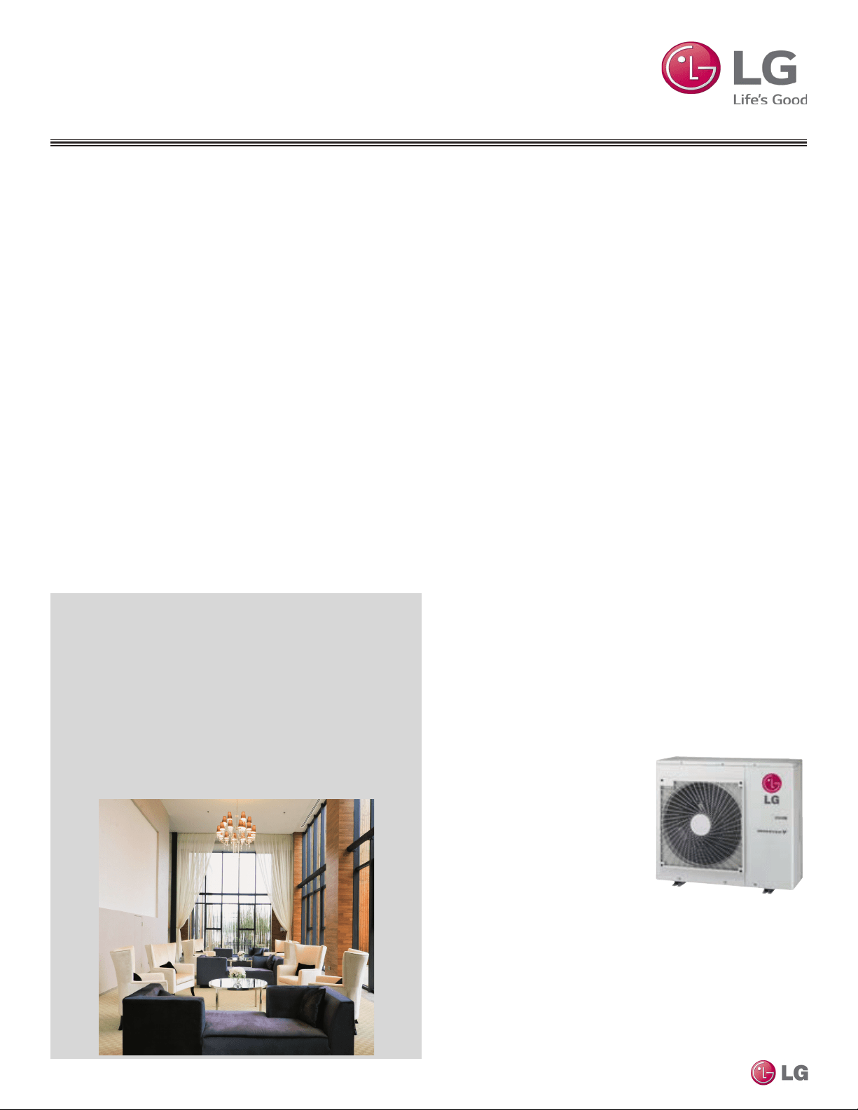
Multi-Zone Systems
LG HVAC systems offer a range of solutions that are cost efficient,
quiet and attractive. Multi-zone systems are “split” into indoor and
outdoor units, and provide a smart alternative to both central HVAC
and window-mounted air conditioners. These inverter heat pump sys-
tems are available in a variety of configurations to suit different cool-
ing and heating situations. Installation by a trained HVAC contractor
is safe and easy – little to no duct work or sheet metal is required.
Multi F Systems
LG’s inverter heat pumps can support two, three, or four indoor
units that are typically installed in separate rooms. Indoor units can
be used with different controllers, allowing the customer to set the
temperature individually. Indoor units are available in several different
congurations: Art Cool™ Mirror-mounted, Art Cool Gallery wall-
mounted, standard wall-mounted, low wall console, four-way ceiling
cassettes, ceiling-concealed duct (high and low static), and vertical-
horizontal air handling models. Multi F MAX systems can operate up
to eight indoor units through two-, three-, or four-port branch distribu-
tion units.
Adaptable and Flexible
Multi F outdoor units can be adapted to a wide range of building ap-
plications and sizes such as schools, hotels, hospitals, ofces, and
residences. The system components are lightweight and compact so
they can be placed in buildings without expensive cranes, they easily
fit into most service elevators, and they can be set in place with
minimal structural reinforcements requirements.
Multi F technology allows you to pipe farther by reaching areas of the
building that would require the installation of a second system when
using traditional direct-expansion cooling and heating equipment. Multi
F provides the designer with uncompromised pipe system engineering
exibility—long pipe runs and large elevation differences. Whether your
building is a condominium, a hotel, a school, or an ofce complex, Multi
F is best suited to reach the farthest corners and elevations.
Smaller Chases and Plenums
LG Multi F systems use refrigerant piping to move heat, resulting in
smaller space requirements for piping as compared to chilled water
or roof top systems. This helps reduce the overall construction and
material cost of the building, and gives back leasable space. Flexible
and logical placement of system components, reduced back-and-
forth pipe lengths, and fewer joints lowers installation costs and
minimizes potential leaking.
Quality Commitment
LG is committed to the success of duct-free projects. We provide
technical support during installation and commissioning. LG offers
a variety of classes designed for
installers and servicers on Multi
F installation. Classes are con-
ducted at LG’s training centers
and in field locations at various
times throughout the year and on
special request.
Benefits of Multi F Systems
• Individual zone control
• Long refrigerant piping lengths
• High refrigerant piping elevation differences
• Maximum flexibility
• Operating ranges of 14°F to 118°F (DB) in cooling and -4°F to
75°F (DB) in heating if connected to standard Multi F Outdoor Units
or -13°F to 75°F (DB) in heating if connected to Multi F with LG
REDº Outdoor Units.
• Quiet and comfortable environment
• Reduced ductwork
CONVERGENCE OF TECHNOLOGY,
INNOVATION, FLEXIBILITY, & STYLE
MULTI
F
Due to our policy of continuous product innovation, some specications may change without notication.
©LG Electronics U.S.A., Inc., Englewood Cliffs, NJ. All rights reserved. “LG” is a registered trademark of LG Corp.
INTRODUCTION | 5
Introduction
MULTI
F
MAX
MULTI
F
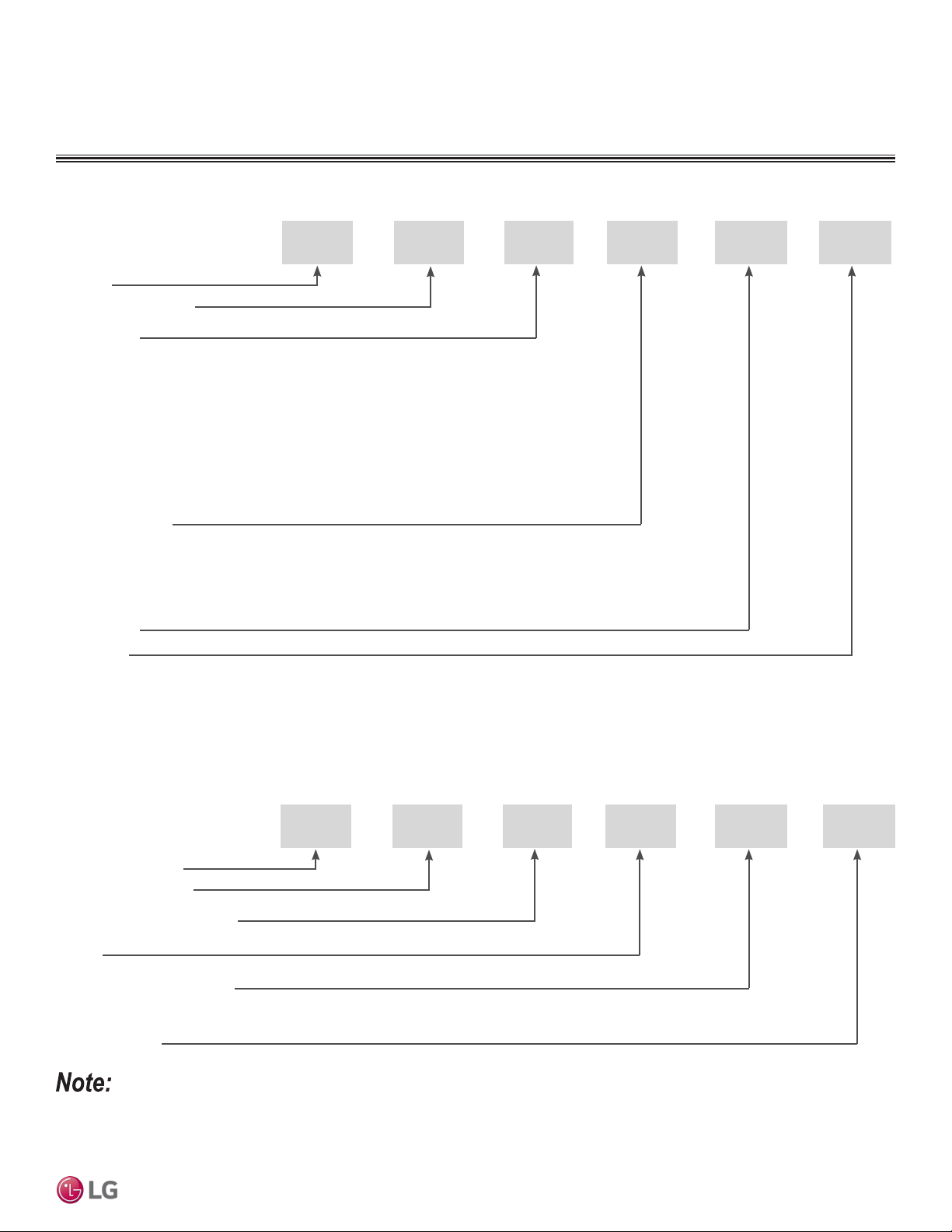
UNIT NOMENCLATURE
Multi-Zone Systems — Indoor Units and Outdoor Units
M
CN 07 8 HV
Generation
Features:
H = Heat Pump
V = Inverter
T = High Wall-Mounted Indoor Unit
P = Art Cool Gallery Indoor Unit
Nominal Capacity
(Nominal cooling capacity in Btu/h):
Component:
AN: Art Cool™ Wall-Mounted Indoor Unit
N: Standard Wall-Mounted Indoor Unit
QN: Low Wall Console Indoor Unit
CN: Four-Way Ceiling-Cassette Indoor Unit
DN: Ceiling-Concealed Duct (Low Static) Indoor Unit
HN: Ceiling-Concealed Duct (High Static) Indoor Unit
VN: Vertical-Horizontal Air Handling Indoor Unit
U: Outdoor Unit
L = LG
07 = 7,000
09 = 9,000
12 = 12,000
15 = 15,000
18 = 18,000
24 = 24,000
30 = 30,000
36 = 36,000
42 = 42,000
48 = 48,000
54 = 54,000
60 = 60,000
L
Type: M = Multi-Zone
Branch Distribution Units
M
BD 36
BD: Branch Distribution Unit
P = Part (Accessory)
P
Type: M = Multi-Zone
Family
Number of Port Connections
(Maximum Number of Connectable Indoor Units): 2, 3, 4
Generation: 0, 1
02
• Voltage for all equipment is 208-230V, 60 Hz, 1-phase.
• All indoor units are compatible with wired controllers.
• All outdoor units are LGAP control network compatible with PI-485 V-net Control Integration Board (PMNFP14A1, sold separately).
• Compatible single zone IDU nomenclature is listed in the Single Zone Wall-Mounted IDU Engineering Manual.
Due to our policy of continuous product innovation, some specications may change without notication.
©LG Electronics U.S.A., Inc., Englewood Cliffs, NJ. All rights reserved. “LG” is a registered trademark of LG Corp.
6 | INTRODUCTION
Multi F and Multi F MAX Indoor Unit Engineering Manual
MULTI
F
MAX
MULTI
F
FUNCTIONS, CONTROLS AND
OPTIONS OVERVIEW
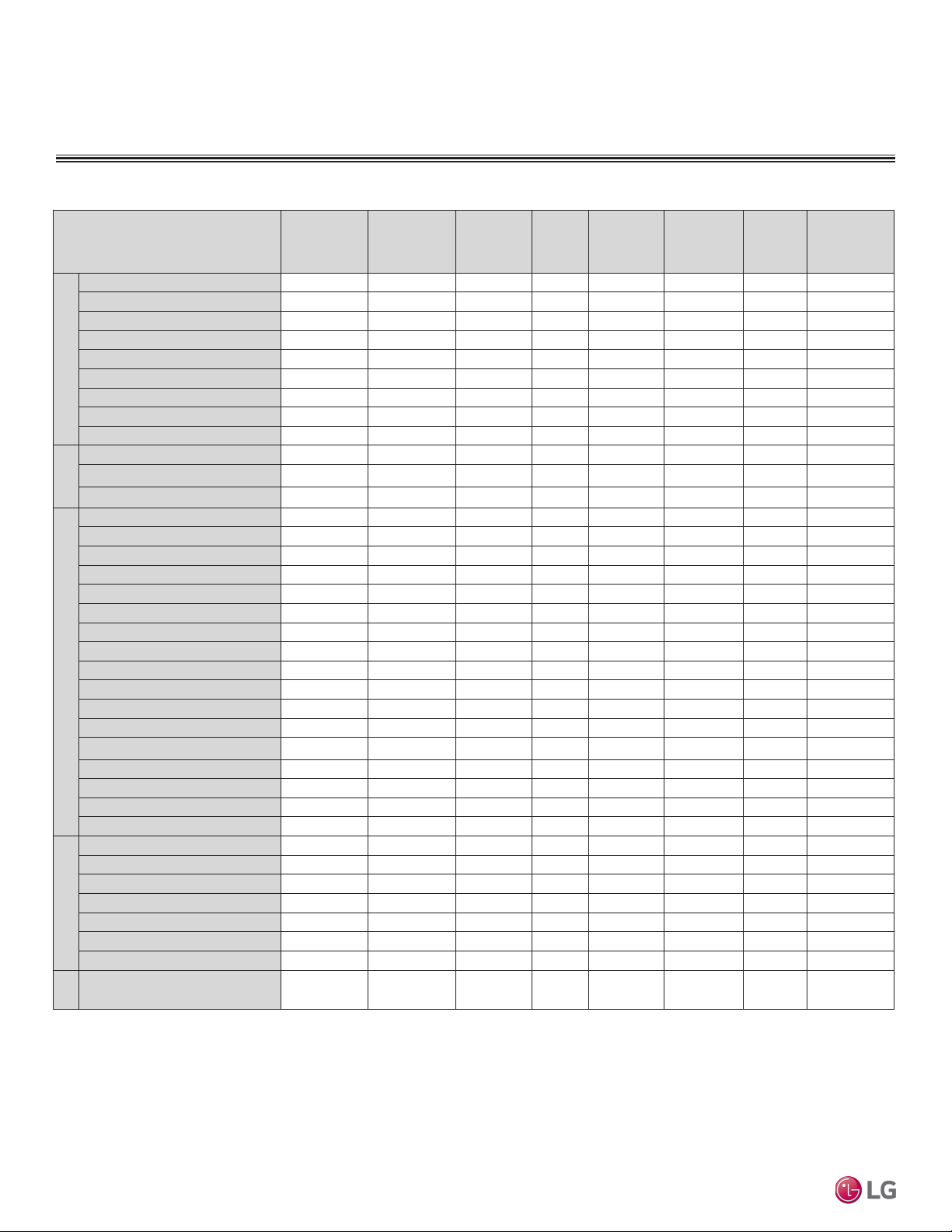
Table 1: Indoor Units—Functions, Controls and Options.
Indoor Unit Type
ART COOL™
Mirror Wall
Mounted
ART COOL™
Gallery
Standard
Wall
Mounted
Low Wall
Console
Ceiling
Concealed
(Low Static)
Ducted
Ceiling
Concealed
(High Static)
Ducted
Four-Way
Ceiling
Cassette
Vertical-
Horizontal Air
Handling Unit
Airow
Air supply outlets
1 3 1 2 1 1 4 1
Airflow direction (left/right)
Auto Auto Auto Manual
Airflow direction (up/down)
Auto Auto Auto Auto Auto
Auto swing (left/right)
√ √ √
Auto swing (up/down)
√ √ √ √ √
Airflow steps (fan/cool/heat)
6 / 6 / 6 5 / 5 / 4 6 / 6 / 6 5 / 5 / 5 3 / 3 / 3 3 / 3 / 3 4 / 5 / 4 3 / 3 / 3
Comfort Air (random fan speed)
√ √ √ √ √
Jet-cool/Jet Heat (power wind)
√ √ √ √ √
Swirl wind
√
Filter
Washable anti-fungal
1
√ √ √ √ √ √ √
3M Micro Dust Filter
2
√ √
Ventilation
√
4
Operation
Drain pump
√ √ √
E.S.P. control
√ √
Electric heater
o
High ceiling
5
√
Hot Start
√ √ √ √ √ √ √ √
Self diagnostics
√ √ √ √ √ √ √ √
Soft Dry (dehumidification)
√ √ √ √ √ √ √
Auto operation
√ √ √ √ √ √ √ √
Auto clean (coil dry)
√ √ √
Auto restart
√ √ √ √ √ √ √
Child lock
o o o √
6
o o o o
Forced operation
√ √ √ √ √
Group control
o o o √
6
o o o o
5
Sleep mode
√ √ √ √ √ √ √ √
Timer (on/off)
√ √ √ √ √ √ √ √
Weekly schedule
o o o √ √ √ o √
Two thermistor control
o o o √ o o o o
Controllers
7-Day programmable controller
o o o o o o o o
Simple wired remote controller
o o o o o o o o
Wireless LCD remote control
√ √ √ √ o
6
o
6
√ o
6
Dry contact
o o o o o o o √
7
Dry contact (temperature setting)
o o o o o o o o
Central control (LGAP)
√ √ √ √ √ √ √ √
Connector for Water Sensor
√ √ √ √
Special
Function
Wi-Fi
8
√ o √ o o o o o
1
Primary washable filters.
2
Secondary filter
3
Branch location and static pressure requirements. Requires PTPKQ0
Plasma kit.
4
Requires ventilation kit PTVK430 (Temperature, humidity, and volume
limitations apply).
5
Group control will affect available features
6
Requires wired zone controller
7
For use with 3rd party thermostat
8
Embedded. Optional for HSD, LVNxxxHV4 4-way VAHU; LDN 9/12 MBH
LSD are compatible as of June 2018 production. Not available for 2-way
LMVNxxxHV VAHU. LMANxxxHVP Art Cool Gallery compatible as of
January 2019 production.
√ = Standard feature
o = Unit option
Due to our policy of continuous product innovation, some specications may change without notication.
©LG Electronics U.S.A., Inc., Englewood Cliffs, NJ. All rights reserved. “LG” is a registered trademark of LG Corp.
INTRODUCTION | 7
Introduction
MULTI
F
MAX
MULTI
F
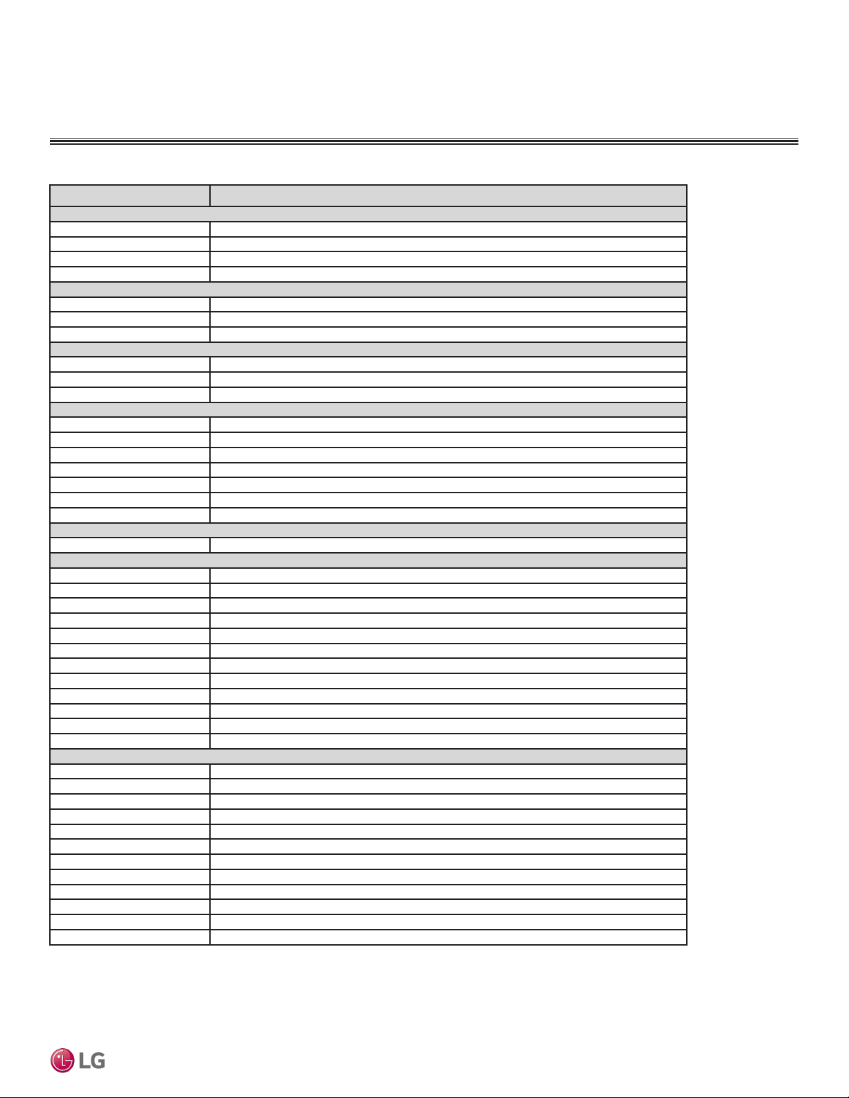
Table 2: Indoor Unit Accessories Overview.
Model No. Description
For Four-Way Ceiling-Cassette Indoor Units
PT-QCHW0 Ceiling Grille
PTDCQ Decorative Cover
PRARH0 Aux Heat Relay Kit
PWFMDD200 Wi-Fi Module
For Wall-Mounted Indoor Units
PWFMDD200 Wi-Fi Module
AG-9300-LG Condensate Sensor
PRARS1 Aux Heat Relay Kit
For Low Wall Console Units
PWFMDD200 Wi-Fi Module
AG-9300-LG Condensate Sensor
PRARH0 Aux Heat Relay Kit
For Vertical-Horizontal Air Handing Units
PNDFJ0 Downflow Conversion Kit (18/24/36MBH)
ANEH033B1 3 kW Electric Heater (18-36MBH)
ANEH053B1 5 kW Electric Heater (18-36MBH)
ANEH083B2 8 kW Electric Heater (18-36MBH)
ANEH103B2 10 kW Electric Heater (18-36MBH)
PRARH0 Aux Heat Relay Kit
PWFMDD200 Wi-Fi Module
For Ceiling-Concealed Duct (Low Static) Indoor Units
PWFMDD200 Wi-Fi Module
For Ceiling-Concealed Duct (High Static) Indoor Units
ZFBXM101A High Efficiency Filter Box for LHN248HV
ZFBXM201A High Efficiency Filter Box for LHN368HV
ZFBXD201A Dynamic V8 2VL Low Profile Air Cleaner
ZPLMV201A Dynamic 2VL Air Cleaner Low Profile Return Air Plenum
ZFBXD402A Dynamic V8 4VL Low Profile Air Cleaner
ZPLMV402A Dynamic 4VL Air Cleaner Low Profile Return Air Plenum
ZFLT1301A 4-Pack Dynamic V8 VL Air Cleaner Replacement Filter Pads
ZFLT1302A 24-Pack Dynamic V8 VL Air Cleaner Replacement Filter Pads
ZGRLRA01A Dynamic V8 Air Cleaner Louvered Return Air Grille (one per plenum )
ZGRLRA02A Dynamic V8 Air Cleaner Egg Crate Return Air Grille (one per plenum)
PRARH0 Aux Heat Relay Kit
PWFMDD200 Wi-Fi Module
Controls Accessories
PQWRHQ0FDB Wireless Handheld Remote (Duct/VAHU)
PREMTA000A Premium Controller
PREMTC00U Simple Controller
PREMTBVC0 MultiSITE CRC1 Base Controller
PREMTBVC1 MultiSITE CRC1 Plus Controller
ZVRCZ**** MultiSITE CRC1 Wireless Accessories
PDRYCB100 Dry Contact (Simple)
PDRYCB300 Dry Contact (3rd party controller)
PDRYCB400 Dry Contact (Setback)
ZRTBS01 Remote Temp Sensor (Cassette/Console/Duct/VAHU)
PZCWRCG3 Group Control Cable Kit
PZCWRC1 Controller Extension Cable
FUNCTIONS, CONTROLS AND
OPTIONS OVERVIEW

Due to our policy of continuous product innovation, some specications may change without notication.
©LG Electronics U.S.A., Inc., Englewood Cliffs, NJ. All rights reserved. “LG” is a registered trademark of LG Corp.
8 | INTRODUCTION
Multi F and Multi F MAX Indoor Unit Engineering Manual
MULTI
F
MAX
MULTI
F

“Mechanical Specifications” on page 10
“General Data / Specifications” on page 11
“Dimensions” on page 12
“Cooling Capacity Table” on page 14
“Heating Capacity Table” on page 16
“Acoustic Data” on page 17
“Air Velocity and Temperature Distribution” on page 18
“Refrigerant Flow Diagram” on page 19
“Wiring Diagram” on page 20
“Factory Supplied Parts and Materials” on page 21
“Installation and Best Layout Practices” on page 22
ART COO
L
™
MIRROR
INDOOR UNIT DATA
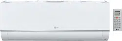
ART COOL Mirror Wall-Mounted
Indoor Units
General
All LG indoor units are factory assembled, wired, piped, and pro-
vided with a control circuit board, fan, and motor. ART COOL Mirror
Wall-Mounted indoor units have a sound rating no higher than 44
dB(A) as tested per KSA0701 ISO Standard 3745.
Coil
Indoor unit coils are comprised of a minimum of two rows of
aluminum fins mechanically bonded to copper tubing. The coils are
pressure tested at the factory. Each unit is provided with a factory
installed condensate drain pan below the coil.
Refrigerant System
System is designed for use with R410A refrigerant. The refrigeration
circuit is pressure-tested at the factory and shipped with a holding
charge of helium gas. Refrigerant pipe connections are 45° flare.
All refrigerant lines from the outdoor unit to the indoor units must be
field insulated.
Electrical
Each indoor unit is designed to operate using 208–230/60/1 power
with voltage variances of ±10%.
Casing
Units are designed to mount on a vertical surface, and are shipped
with a separate back plate that secures the unit to the wall, protrud-
ing no more than nine (9) inches. Unit is designed so that refrigerant
piping can be installed in one (1) of four (4) different directions.
Finish
The Art Cool Mirror unit has a flat, architectural panel with a smoked
charcoal mirror finish. Unit casing has a dark grey finish and is
manufactured of heavy-duty acrylonitrile butadiene styrene (ABS)
and high impact polystyrene (HIPS) plastic.
Fan Assembly and Control
The unit has a single, direct-drive, crossow fan made of high strength
ABS plastic. The fan motor is brushless digitally controlled (BLDC)
with permanently lubricated and sealed ball bearings. The fan and
motor assembly is mounted on vibration attenuating rubber grommets.
Fan speed is controlled using a microprocessor-based direct digitally
controlled algorithm that provides pre-programmed, eld-selectable
xed or auto fan speeds in the Heating and Cooling modes. For Art
Cool Mirror Wall-Mounted units, the indoor fan has Low, Med, High,
Jet Cool and Auto settings for Cooling mode; and has Low, Med, High,
Jet Heat and Auto settings for Heating mode. The Auto setting adjusts
the fan speed based on the difference between the controller setpoint
and space temperature. Also, the separate Chaos setting provides a
simultaneous and random change in fan speed and ow direction at
the discharge, simulating a natural outdoor breeze.
Air Filter
Return air inlet has a factory-supplied primary removable, washable
filter. The unit is also equipped with a secondary 3M Micro Dust
filter. Filters are accessed from the front of the unit without the use
of tools.
Airflow Guide Vanes
A motorized guide vane is factory installed, and allows the ability to
control the direction of airflow from side to side. A motorized louver
provides an automatic change in airflow by directing the air up and
down to provide uniform air distribution.
Microprocessor Control
The indoor unit is provided with an integrated control panel to com-
municate with the outdoor unit. All unit operation parameters are
stored in non-volatile memory resident on the unit microprocessor.
The microprocessor controls space temperature through using the
value provided by the temperature sensor within the indoor unit.
The microprocessor control will activate indoor unit operation when
the indoor room temperature falls below or rises above a setpoint
temperature, at which point, a signal is sent to the outdoor unit to
begin the appropriate mode. The microprocessor will also provide
self-diagnostics and auto restart functions. A field-supplied four-wire
power/communications cable must be installed to connect the indoor
unit(s) to the outdoor unit.
Controls
The indoor unit casing has a factory-standard, integral infrared
sensor designed to communicate with the supplied LG wireless
handheld remote controller. An optional LG supplied wired controller
is available as an additional accessory. Communication between the
indoor units and the outdoor unit is accomplished through 14 AWG,
four-core, stranded and shielded power/communication cable. The
indoor unit has built-in wi-fi and can be controlled with LG’s Smart-
ThinQ app on a smart device. A field-supplied wi-fi network and
smart device are required. The SmartThinQ app is free and is avail-
able for Android and iOS smart devices.
Condensate
The unit is designed for gravity draining of condensate and includes
a flexible drain hose capable of installation in one of two directions.
Unit includes a connection that is compatible with the AquaGuard
®
AG-9300-LG condensate sensor.
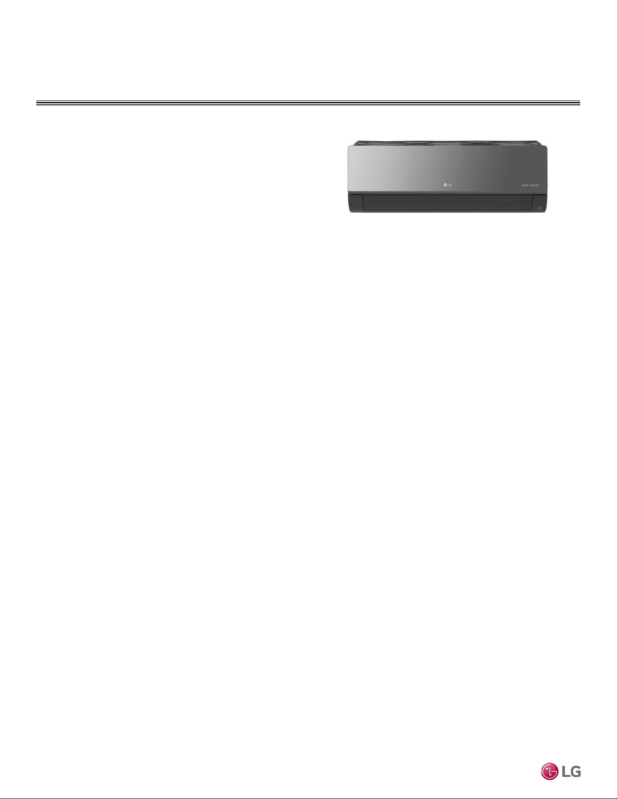
ART COOL MIRROR INDOOR UNITS
Mechanical Specications and Features
• Inverter (Variable speed fan)
• Comfort Air
• 3M filter
• Jet cool/Jet heat
• Group Control
• Self-cleaning indoor coil
• Auto operation
• Auto restart operation
• Built-in wi-fi
• Dehumidifying function
• Self diagnosis function
• Wireless LCD remote control included
Features
Figure 1: Multi F Art Cool Mirror Wall-Mounted Indoor Unit.
Due to our policy of continuous product innovation, some specications may change without notication.
©LG Electronics U.S.A., Inc., Englewood Cliffs, NJ. All rights reserved. “LG” is a registered trademark of LG Corp.
10 | ART COOL MIRROR
Multi F and Multi F MAX Indoor Unit Engineering Manual
MULTI
F
MAX
MULTI
F
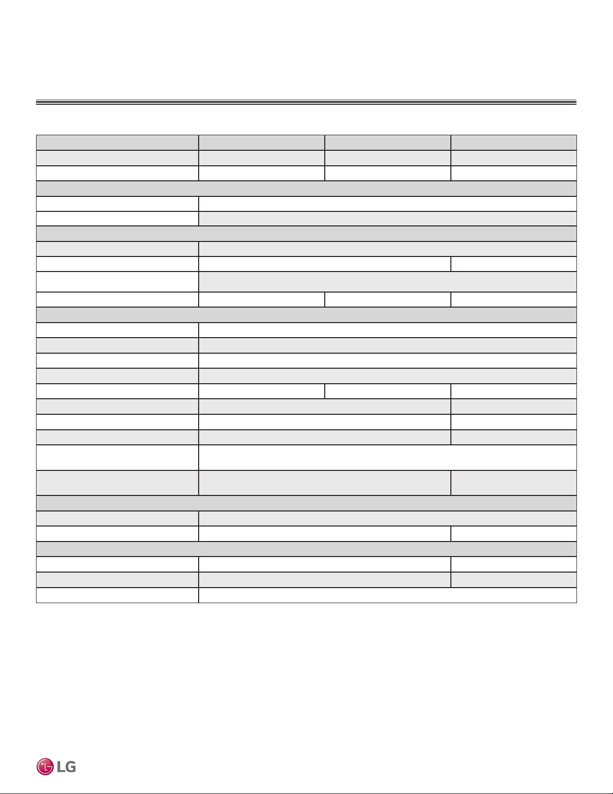
Model Name LAN090HSV5 LAN120HSV5 LAN180HSV5
Nominal Cooling Capacity (Btu/h)
1
9,000 12,000 18,000
Nominal Heating Capacity (Btu/h)
1
10,900 13,600 21,600
Operating Range
Cooling (°F WB)
57-77
Heating (°F DB)
59-81
Fan
Type
Cross Flow
Motor Output (W) x Qty.
30 x 1 60.0 x 1
Motor/Drive
Brushless Digitally Controlled / Direct
Airflow Rate CFM (H/M/L)
268 / 218 / 169 282 / 233 / 177 558 / 438 / 353
Unit Data
Refrigerant Type
2
R410A
Refrigerant Control
EEV
Power Supply V, Ø, Hz
3
208-230, 1, 60
Rated Amps (A)
0.4
Sound Pressure Level dB(A) (H/M/L)
4
36 / 32 / 27 38 / 34 / 29 44 / 38 / 34
Dimensions (W x H x D, in.)
32-15/16 x 12-1/8 x 7-9/16 39-9/32 x 13-19/32 x 8-11/32
Net Unit Weight (lbs.)
20.5 29.8
Shipping Weight (lbs.)
25.6 36.4
Power Wiring / Communications Cable
(No. x AWG)
5
4 x 14
Heat Exchanger
(Row x Column x Fin / inch) x Number
(2 x 23 x 22) x 1 (2 x 16 x 20) x 1
Pipe Size
Liquid (in.)
1/4
Vapor (in.)
3/8 1/2
Connection Size
Liquid (in.)
1/4 3/8
Vapor (in.)
3/8 5/8
Drain O.D. / I.D. (in.)
27/32, 5/8
1
Nominal capacity is rated 0 ft. above sea level with corresponding refrigerant piping length in
accordance with standard length of each outdoor unit and a 0 ft. level difference between outdoor and
indoor units. All capacities are net with a combination ratio between 95 – 105%.
Nominal cooling capacity rating obtained with air entering the indoor unit at 80ºF dry bulb (DB) and 67ºF
wet bulb (WB) and outdoor ambient conditions of 95ºF dry bulb (DB) and 75ºF wet bulb (WB).
Nominal heating capacity rating obtained with air entering the indoor unit at 70ºF dry bulb (DB) and 60ºF
wet bulb (WB) and outdoor ambient conditions of 47ºF dry bulb (DB) and 43ºF wet bulb (WB).
2
This unit comes with a dry helium charge.
3
Acceptable operating voltage: 187V-253V.
4
Sound pressure levels are tested in an anechoic chamber under ISO Standard 3745 and are the
same in both cooling and heating mode. These values can increase due to ambient conditions during
operation.
5
All power wiring / communications cable to the IDUs be minimum 14 AWG, 4-conductor, stranded,
shielded or unshielded (if shielded, must be grounded to chassis at ODU only) and must comply with
applicable local and national codes.
ART COOL MIRROR INDOOR UNITS
General Data / Specications
Table 3: Multi F Art Cool Mirror Indoor Unit General Data.
ART COOL MIRROR | 11
Art Cool Mirror™
Due to our policy of continuous product innovation, some specications may change without notication.
©LG Electronics U.S.A., Inc., Englewood Cliffs, NJ. All rights reserved. “LG” is a registered trademark of LG Corp.
MULTI
F
MAX
MULTI
F
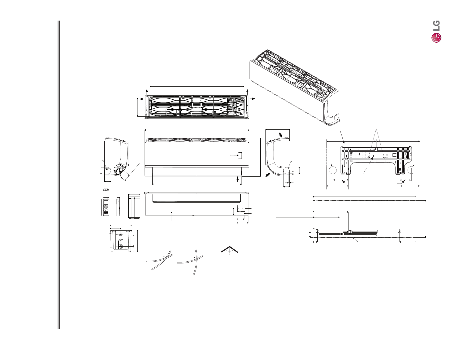
ART COOL MIRROR INDOOR UNITS
Dimensions
Figure 2: LAN090HSV5 and LAN120HSV5 Dimensions.
Unit : inch (mm)
[30-3/16 (767)]
32-15/16 (837)
3-5/8 (92)
2-3/8 (60)
2-5/16
(59)
12-1/8 (308)
7-9/16 (192)
32-15/16 (837)
1-1/2 (38)
Approx. 8-19/32 (218) to liquid pipe
Approx. 11-11/32 (288) to gas pipe
1-27/32(47)
5-3/16 (132)
In Case of Left Side Piping
Unit Outline
Connecting Gas/Liquid Pipe
12-1/8 (308)
2-7/32(56)
11/32 (9)
5/16 (8)
2 (51)
Air Intake
Air Outlet
Bottom
[28-5/32 (715)]
Air Outlet Hole
* If airflow direction control is available,
Cooling Heating
Up & Down Left & Right
Air Outlet Hole
Air Intake Hole
[5-29/32 (150)]
Air Intake Hole
Rear
Rear
Right
Left
55°
15°
15°
85°
45°
55°
1-3/32 (50.2)
1-1/16 (26.2)
5-31/32 (152)
2-7/32 (56)
2 (51)
2-7/32 (56)
Decoration Cover
Terminal Block for
Power Supply and
Communication
Display & Remote
Controller Signal
Receiver Signal
Refrigerant, Drain
Pipe, and Cable
Knock Out Hole
Drain Hose
Connection
Refrigerant, Drain
Pipe and Cable
Knock Out Hole
Refrigerant,
Drain Pipe
and Cable
Knock
Out Hole
2-7/16 ( 61.5)
1-9/32 (32.7)
2-13/32
(61)
1/4 (6) x 1/8 (3)
1/8 (3) x 1/4 (6)
5/8 (15.3)
1-1/4 (31)
1-7/16 (33.5)
Attaching the Installation Plate, Drilling Hole
7.66
Ø2-9/16”
Ø2-9/16"
Right Rear piping
Left Rear piping
Ø2-9/16"
C Type : 5.3C Type : 3.9
C Type
C Type : 16.5 C Type : 16.5
Place a Level on Raised Tab
Unit Outline
Installation Plate
Due to our policy of continuous product innovation, some specications may change without notication.
©LG Electronics U.S.A., Inc., Englewood Cliffs, NJ. All rights reserved. “LG” is a registered trademark of LG Corp.
12 | ART COOL MIRROR
Multi F and Multi F MAX Indoor Unit Engineering Manual
MULTI
F
MAX
MULTI
F
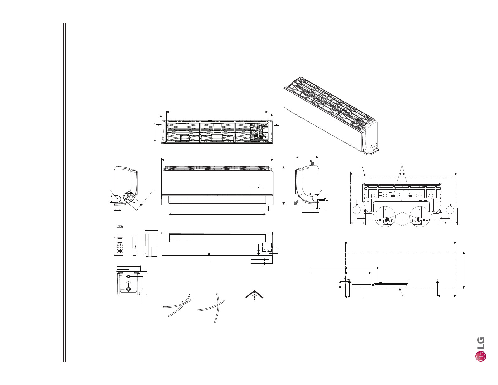
ART COOL MIRROR INDOOR UNITS
Dimensions
Figure 3: LAN180HSV5 Dimensions.
Unit : inch (mm)
[36-5/32 (918)]
Air Intake Hole
[6-11/16 (170)]
Air Intake Hole
ir Outlet Ho
[2-29/32 (74)]
Rear
A le
39-9/32 (998)
2-1/4 (57)
2-7/32 (56)
3-17/32 (90)
Bottom
Air
Outlet
[34-11/32 (872)]
Air Outlet Hole
13-19/32 (345)
2-3/8 (60)
7/16(11)
Air Intake
8-11/32 (212)
13-19/32 (345)
39-9/32 (998)
6-15/32 (164)
1-15/32 (37)
2-15/32 (63)
In case of Left Side Piping
Unit Outline
Approx. 9-7/16 (240) to gas pipe
Approx. 6-5/16 (160) to liquid pipe
Connecting Gas/Liquid Pipe
2-3/8 (60)
2-3/8 (60)
Rear
Left
Right
If airflow direction control is available,*
Cooling Heating
Up & Down Left & Right
50°
15°
20°
85°
45°
50°
7/16 (11)
1-3/32 (50.2)
1-1/16 (26.2)
5-31/32 (152)
2-3/8 (60)
Terminal Block for
Power Supply and
Communication
Refrigerant, Drain
Pipe and Cable
Knock Out Hole
Refrigerant, Drain
Pipe, and Cable
Knock Out Hole
Display & Remote
Controller Signal
Receiver Signal
Decoration Cover
Refrigerant,
Drain Pipe
and Cable
Knock
Out Hole
Drain Hose Connection
2-7/16 ( 61.5)
1-9/32 (32.7)
2-13/32
(61)
1/4 (6) x 1/8 (3)
1/8 (3) x 1/4 (6)
5/8 (15.3)
1-1/4 (31)
1-7/16 (33.5)
Attaching the Installation Plate, Drilling Hole
C Type: 19.4 C Type: 19.8
Place a Level on Raised Tab
Unit Outline
3.3
C Type: 5.3
Measuring Tape
Ø2-9/16"
3.3
Measuring Tape
Hanger
Ø2-9/16
"
C Type: 5.9
Right Rear piping
Left Rear piping
ART COOL MIRROR | 13
Art Cool Mirror™
Due to our policy of continuous product innovation, some specications may change without notication.
©LG Electronics U.S.A., Inc., Englewood Cliffs, NJ. All rights reserved. “LG” is a registered trademark of LG Corp.
MULTI
F
MAX
MULTI
F
ART COOL MIRROR INDOOR UNITS
Cooling Capacity Table
Model No. /
Nominal Capacity
of Indoor Unit
(Btu/h)
Outdoor Air
Temp.
(°F DB)
Indoor Air Temp. °F DB / °F WB
68 / 57 73 / 61 77 / 64 80 / 67 86 / 72 90 / 75
TC SHC TC SHC TC SHC TC SHC TC SHC TC SHC
LAN090HSV5
9,000
14 8.82 6.04 9.37 6.38 9.92 6.18 10.31 6.31 11.01 6.36 11.56 6.48
20 8.82 6.09 9.36 6.43 9.91 6.23 10.31 6.36 11.01 6.41 11.55 6.53
25 8.81 6.13 9.36 6.48 9.90 6.27 10.30 6.41 11.00 6.46 11.54 6.58
30 8.80 6.18 9.35 6.53 9.90 6.32 10.29 6.46 10.99 6.51 11.54 6.63
35 8.80 6.23 9.34 6.58 9.89 6.37 10.28 6.50 10.98 6.56 11.53 6.68
40 8.79 6.28 9.33 6.63 9.88 6.42 10.27 6.55 10.97 6.61 11.52 6.73
45 8.78 6.32 9.33 6.68 9.87 6.47 10.27 6.60 10.96 6.66 11.51 6.78
50 8.78 6.37 9.32 6.73 9.87 6.51 10.26 6.65 10.96 6.71 11.50 6.83
55 8.77 6.42 9.31 6.78 9.86 6.56 10.25 6.70 10.95 6.76 11.49 6.88
60 8.76 6.46 9.31 6.83 9.85 6.61 10.24 6.75 10.94 6.81 11.48 6.93
65 8.76 6.51 9.30 6.88 9.84 6.66 10.24 6.80 10.93 6.85 11.47 6.98
70 8.75 6.56 9.29 6.92 9.84 6.70 10.23 6.85 10.92 6.90 11.47 7.03
75 8.54 6.45 9.08 6.82 9.62 6.61 10.01 6.75 10.71 6.82 11.25 6.96
80 8.33 6.34 8.87 6.71 9.41 6.51 9.80 6.66 10.49 6.73 11.03 6.87
85 8.12 6.22 8.66 6.60 9.20 6.41 9.59 6.56 10.28 6.64 10.82 6.79
90 7.91 6.10 8.45 6.48 8.99 6.31 9.37 6.46 10.06 6.55 10.60 6.70
95 7.68 6.04 8.22 6.43 8.75 6.26 9.00 6.32 9.83 6.52 10.36 6.67
100 7.50 5.88 8.03 6.26 8.57 6.11 8.88 6.22 9.64 6.37 10.17 6.53
105 7.31 5.72 7.84 6.10 8.38 5.96 8.77 6.12 9.45 6.23 9.99 6.39
110 7.12 5.52 7.66 5.90 8.19 5.78 8.58 5.94 9.26 6.06 9.80 6.22
115 6.94 5.36 7.47 5.74 8.01 5.63 8.39 5.79 9.08 5.91 9.61 6.08
118 6.82 5.32 7.36 5.70 7.89 5.60 8.28 5.76 8.96 5.89 9.50 6.06
122 6.79 5.30 7.32 5.69 7.86 5.59 8.24 5.76 8.93 5.89 9.46 6.06
LAN120HSV5
12,000
14 11.76 8.51 12.49 8.99 13.22 8.70 13.75 8.88 14.69 8.96 15.42 9.13
20 11.75 8.57 12.48 9.06 13.21 8.77 13.74 8.95 14.67 9.03 15.40 9.20
25 11.75 8.64 12.48 9.13 13.20 8.84 13.73 9.02 14.66 9.10 15.39 9.27
30 11.74 8.71 12.47 9.20 13.19 8.90 13.72 9.09 14.65 9.17 15.38 9.34
35 11.73 8.77 12.46 9.27 13.18 8.97 13.71 9.16 14.64 9.24 15.37 9.41
40 11.72 8.84 12.45 9.34 13.17 9.04 13.70 9.23 14.63 9.31 15.36 9.48
45 11.71 8.90 12.44 9.41 13.16 9.11 13.69 9.30 14.62 9.38 15.35 9.55
50 11.70 8.97 12.43 9.47 13.15 9.17 13.68 9.37 14.61 9.45 15.33 9.62
55 11.69 9.03 12.42 9.54 13.14 9.24 13.67 9.44 14.60 9.52 15.32 9.70
60 11.68 9.10 12.41 9.61 13.13 9.31 13.66 9.50 14.59 9.58 15.31 9.77
65 11.67 9.17 12.40 9.68 13.12 9.38 13.65 9.57 14.57 9.65 15.30 9.84
70 11.66 9.23 12.39 9.75 13.11 9.44 13.64 9.64 14.56 9.72 15.29 9.91
75 11.38 9.08 12.11 9.60 12.83 9.31 13.35 9.51 14.27 9.60 15.00 9.79
80 11.10 8.92 11.82 9.45 12.55 9.17 13.07 9.38 13.99 9.48 14.71 9.68
85 10.83 8.76 11.54 9.29 12.26 9.03 12.78 9.24 13.70 9.36 14.42 9.56
90 10.55 8.60 11.26 9.13 11.98 8.88 12.50 9.10 13.42 9.22 14.13 9.43
95 10.25 8.51 10.96 9.05 11.67 8.82 12.00 8.90 13.10 9.18 13.81 9.39
100 10.00 8.28 10.71 8.82 11.42 8.61 11.84 8.76 12.85 8.98 13.56 9.20
105 9.75 8.05 10.46 8.59 11.17 8.40 11.69 8.62 12.60 8.78 13.31 9.01
110 9.50 7.77 10.21 8.31 10.92 8.14 11.44 8.37 12.35 8.53 13.07 8.76
115 9.25 7.54 9.96 8.08 10.67 7.92 11.19 8.15 12.10 8.33 12.82 8.56
118 9.10 7.49 9.81 8.03 10.52 7.88 11.04 8.12 11.95 8.30 12.67 8.54
122 9.05 7.47 9.76 8.01 10.48 7.87 10.99 8.11 11.90 8.29 12.62 8.53
Table 4: Multi F Art Cool Mirror Indoor Units Cooling Capacity Table.
TC = Total Capacity (kBtu/h).
SHC: Sensible Heat Capacity (kBtu/h).
Nominal capacity as rated 0 ft. above sea level and a 0 ft. level difference between outdoor and indoor units. Corresponding refrigerant piping length is accordance with standard length of each outdoor unit.
Nominal cooling capacity rating obtained with air entering the indoor unit at 80ºF dry bulb (DB) and 67ºF wet bulb (WB), and outdoor ambient conditions of 95ºF dry bulb (DB) and 75ºF wet bulb (WB).
The shaded table columns and rows indicate reference data. When operating at this temperature, these values can be different if the system is not running consistently.
Due to our policy of continuous product innovation, some specications may change without notication.
©LG Electronics U.S.A., Inc., Englewood Cliffs, NJ. All rights reserved. “LG” is a registered trademark of LG Corp.
14 | ART COOL MIRROR
Multi F and Multi F MAX Indoor Unit Engineering Manual
MULTI
F
MAX
MULTI
F
Model No. /
Nominal Capacity
of Indoor Unit
(Btu/h)
Outdoor Air
Temp.
(°F DB)
Indoor Air Temp. °F DB / °F WB
68 / 57 73 / 61 77 / 64 80 / 67 86 / 72 90 / 75
TC SHC TC SHC TC SHC TC SHC TC SHC TC SHC
LAN180HSV5
18,000
14 17.65 12.33 18.74 13.02 19.84 12.61 20.63 12.88 22.03 12.98 23.12 13.23
20 17.63 12.43 18.73 13.13 19.82 12.71 20.61 12.98 22.01 13.09 23.11 13.33
25 17.62 12.52 18.71 13.23 19.81 12.81 20.60 13.08 22.00 13.19 23.09 13.44
30 17.60 12.62 18.70 13.33 19.79 12.91 20.58 13.18 21.98 13.29 23.07 13.54
35 17.59 12.71 18.68 13.43 19.78 13.00 20.57 13.28 21.96 13.39 23.05 13.64
40 17.58 12.81 18.67 13.53 19.76 13.10 20.55 13.38 21.94 13.49 23.04 13.75
45 17.56 12.90 18.66 13.63 19.75 13.20 20.53 13.48 21.93 13.59 23.02 13.85
50 17.55 13.00 18.64 13.73 19.73 13.30 20.52 13.58 21.91 13.69 23.00 13.95
55 17.54 13.10 18.63 13.83 19.72 13.39 20.50 13.68 21.89 13.79 22.98 14.05
60 17.52 13.19 18.61 13.93 19.70 13.49 20.49 13.78 21.88 13.89 22.97 14.16
65 17.51 13.29 18.60 14.03 19.69 13.59 20.47 13.87 21.86 13.99 22.95 14.26
70 17.50 13.38 18.58 14.13 19.67 13.69 20.46 13.97 21.84 14.09 22.93 14.36
75 17.08 13.16 18.16 13.92 19.24 13.49 20.03 13.79 21.41 13.92 22.50 14.20
80 16.66 12.93 17.74 13.70 18.82 13.30 19.60 13.60 20.98 13.75 22.06 14.03
85 16.24 12.70 17.32 13.47 18.40 13.09 19.17 13.40 20.55 13.56 21.63 13.85
90 15.82 12.46 16.90 13.23 17.97 12.88 18.75 13.19 20.12 13.37 21.20 13.67
95 15.37 12.33 16.44 13.12 17.51 12.78 18.00 12.90 19.65 13.30 20.72 13.61
100 14.99 12.00 16.06 12.78 17.13 12.47 17.77 12.70 19.28 13.01 20.35 13.33
105 14.62 11.67 15.69 12.45 16.76 12.17 17.53 12.50 18.90 12.73 19.97 13.05
110 14.24 11.27 15.32 12.05 16.39 11.79 17.16 12.13 18.53 12.36 19.60 12.70
115 13.87 10.93 14.94 11.71 16.01 11.48 16.79 11.82 18.15 12.07 19.22 12.41
118 13.65 10.85 14.72 11.64 15.79 11.42 16.56 11.77 17.93 12.03 19.00 12.37
122 13.57 10.83 14.64 11.62 15.71 11.40 16.49 11.75 17.85 12.01 18.92 12.36
Table 5: Multi F Art Cool Mirror Indoor Units Cooling Capacity Table (continued).
TC = Total Capacity (kBtu/h).
SHC: Sensible Heat Capacity (kBtu/h).
Nominal capacity as rated 0 ft. above sea level and a 0 ft. level difference between outdoor and indoor units. Corresponding refrigerant piping length is accordance with standard length of each outdoor unit.
Nominal cooling capacity rating obtained with air entering the indoor unit at 80ºF dry bulb (DB) and 67ºF wet bulb (WB), and outdoor ambient conditions of 95ºF dry bulb (DB) and 75ºF wet bulb (WB).
The shaded table columns and rows indicate reference data. When operating at this temperature, these values can be different if the system is not running consistently.
Cooling Capacity Table
ART COOL MIRROR INDOOR UNITS
ART COOL MIRROR | 15
Art Cool Mirror™
Due to our policy of continuous product innovation, some specications may change without notication.
©LG Electronics U.S.A., Inc., Englewood Cliffs, NJ. All rights reserved. “LG” is a registered trademark of LG Corp.
MULTI
F
MAX
MULTI
F
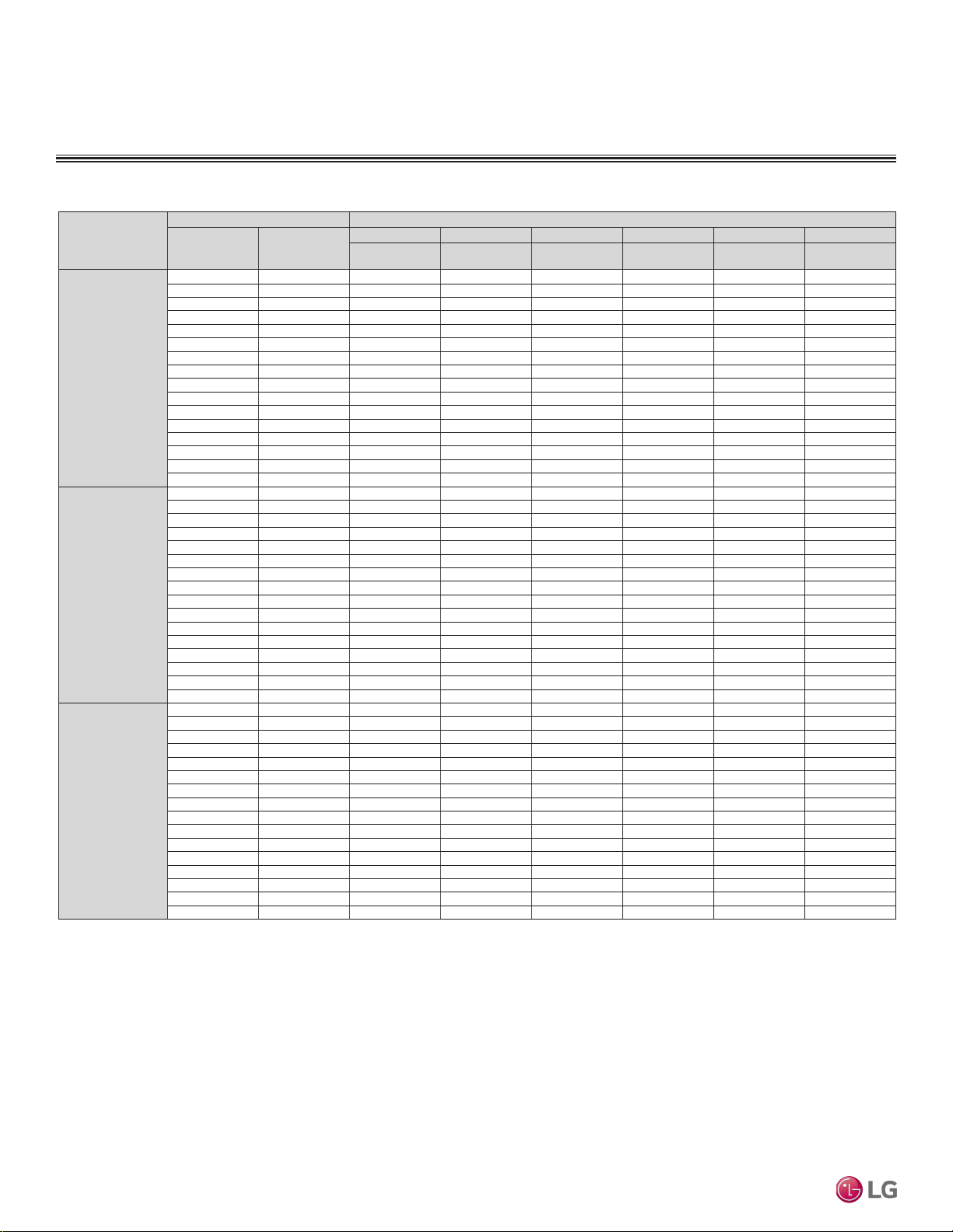
Table 6: Multi F Art Cool Mirror Indoor Units Heating Capacity Table.
TC = Total Capacity (kBtu/h).
Nominal capacity as rated 0 ft. above sea level and a 0 ft. level difference between outdoor and indoor units. Corresponding refrigerant piping length is accordance with standard length of each outdoor unit.
Nominal heating capacity rating obtained with air entering the indoor unit at 70ºF dry bulb (DB) and 60ºF wet bulb (WB), and outdoor ambient conditions of 47ºF dry bulb (DB) and 43ºF wet bulb (WB).
ART COOL MIRROR INDOOR UNITS
Heating Capacity Table
Model No. /
Nominal Capacity of
Indoor Unit
(Btu/h)
Outdoor Air Temp. Indoor Air Temp. °F DB
°F DB °F WB
61 64 68 70 72 75
TC TC TC TC TC TC
LAN090HSV5
10,900
0 -0.4 5.61 5.53 5.48 5.45 5.37 5.14
5 4.5 6.32 6.24 6.18 6.16 6.08 5.85
10 9 7.03 6.95 6.90 6.88 6.79 6.56
17 15 7.98 7.90 7.85 7.82 7.75 7.48
20 19 8.33 8.26 8.21 8.18 8.09 7.82
25 23 8.93 8.85 8.79 8.77 8.69 8.37
30 28 9.44 9.36 9.31 9.29 9.20 8.93
35 32 9.96 9.87 9.82 9.79 9.72 9.47
40 36 10.42 10.33 10.28 10.25 10.18 9.94
45 41 10.87 10.80 10.74 10.71 10.64 10.40
47 43 11.06 10.98 10.93 10.90 10.82 10.59
50 46 11.24 11.15 11.10 11.08 10.99 10.73
55 51 11.53 11.46 11.40 11.37 11.30 10.98
60 56 11.53 11.46 11.40 11.37 11.30 11.03
63 59 11.53 11.46 11.40 11.37 11.30 11.06
68 64 11.53 11.46 11.40 11.37 11.30 11.11
LAN120HSV5
13,600
0 -0.4 7.00 6.90 6.83 6.80 6.70 6.50
5 4.5 7.89 7.78 7.71 7.69 7.59 7.40
10 9 8.78 8.67 8.60 8.58 8.48 8.31
17 15 9.95 9.86 9.79 9.76 9.67 9.47
20 19 10.40 10.30 10.23 10.20 10.10 9.90
25 23 11.14 11.03 10.96 10.95 10.85 10.60
30 28 11.78 11.67 11.60 11.59 11.49 11.30
35 32 12.42 12.31 12.24 12.21 12.13 11.99
40 36 13.00 12.89 12.82 12.79 12.70 12.58
45 41 13.56 13.46 13.39 13.36 13.28 13.16
47 43 13.80 13.70 13.63 13.60 13.50 13.40
50 46 14.02 13.91 13.84 13.82 13.72 13.59
55 51 14.39 14.29 14.22 14.19 14.10 13.90
60 56 14.39 14.29 14.22 14.19 14.10 13.96
63 59 14.39 14.29 14.22 14.19 14.10 14.00
68 64 14.39 14.29 14.22 14.19 14.10 14.06
LAN180HSV5
21,600
0 -0.4 11.11 10.96 10.85 10.80 10.64 10.18
5 4.5 12.52 12.37 12.26 12.21 12.06 11.58
10 9 13.93 13.77 13.67 13.61 13.46 12.99
17 15 15.81 15.65 15.55 15.49 15.34 14.84
20 19 16.51 16.36 16.25 16.20 16.04 15.49
25 23 17.69 17.53 17.43 17.37 17.22 16.59
30 28 18.70 18.55 18.44 18.39 18.24 17.69
35 32 19.72 19.56 19.46 19.41 19.25 18.79
40 36 20.63 20.48 20.37 20.32 20.17 19.70
45 41 21.55 21.39 21.29 21.24 21.08 20.61
47 43 21.91 21.76 21.65 21.60 21.44 20.98
50 46 22.26 22.11 22.01 21.95 21.80 21.27
55 51 22.86 22.70 22.59 22.53 22.38 21.76
60 56 22.86 22.70 22.59 22.53 22.38 21.85
63 59 22.86 22.70 22.59 22.53 22.38 21.91
68 64 22.86 22.70 22.59 22.53 22.38 22.02
Due to our policy of continuous product innovation, some specications may change without notication.
©LG Electronics U.S.A., Inc., Englewood Cliffs, NJ. All rights reserved. “LG” is a registered trademark of LG Corp.
16 | ART COOL MIRROR
Multi F and Multi F MAX Indoor Unit Engineering Manual
MULTI
F
MAX
MULTI
F

• Measurement taken 2.6′ below the bottom of the unit and at a
distance of 3.3′ from face of unit.
• Measurements taken with no attenuation and units operating at full
load normal operating condition.
• Sound level will vary depending on a range of factors such as
construction (acoustic absorption coefficient) of particular area in
which the equipment is installed.
• Sound power levels are measured in dB(A).
• Tested in anechoic chamber per ISO Standard 3745.
2.6 ft.
3.3 ft.
Microphone
Model No.
Sound Pressure Levels (dB[A]) (Cooling and Heating)
High Fan Speed
Medium Fan
Speed
Low Fan Speed
LAN090HSV5 36 32 27
LAN120HSV5 38 34 29
LAN180HSV5 44 38 34
Figure 4: Sound Pressure Level Measurement Location.
Table 7:Sound Pressure Levels (dB[A]).
Figure 5: Sound Pressure Level Diagrams.
ART COOL MIRROR INDOOR UNITS
Acoustic Data
LAN090HSV5 LAN120HSV5
LAN180HSV5
ART COOL MIRROR | 17
Art Cool Mirror™
Due to our policy of continuous product innovation, some specications may change without notication.
©LG Electronics U.S.A., Inc., Englewood Cliffs, NJ. All rights reserved. “LG” is a registered trademark of LG Corp.
MULTI
F
MAX
MULTI
F
ART COOL MIRROR INDOOR UNITS
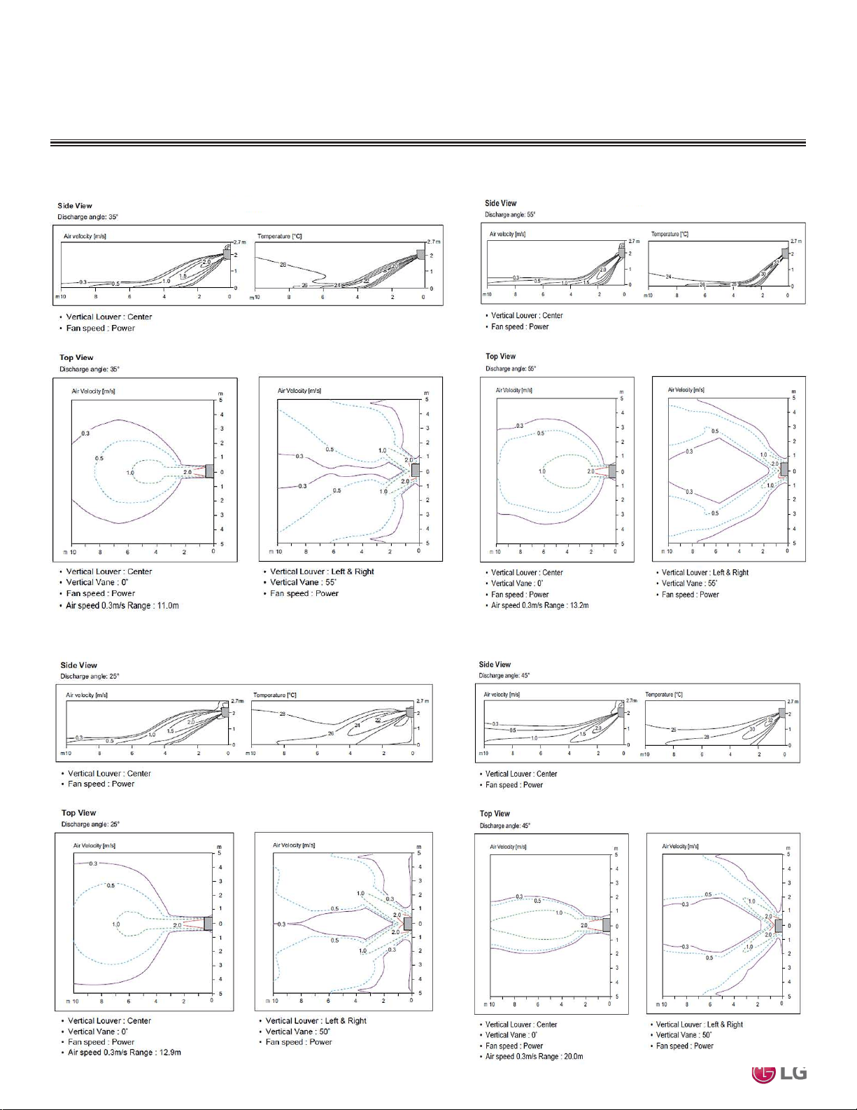
Air Velocity and Temperature Distribution
Figure 6: LAN090HSV5 and LAN120HSV5 Air Velocity and Temperature Distribution Charts.
Figure 7: LAN180HSV5 Air Velocity and Temperature Distribution Charts.
Cooling
Heating
Cooling
Heating
Due to our policy of continuous product innovation, some specications may change without notication.
©LG Electronics U.S.A., Inc., Englewood Cliffs, NJ. All rights reserved. “LG” is a registered trademark of LG Corp.
18 | ART COOL MIRROR
Multi F and Multi F MAX Indoor Unit Engineering Manual
MULTI
F
MAX
MULTI
F
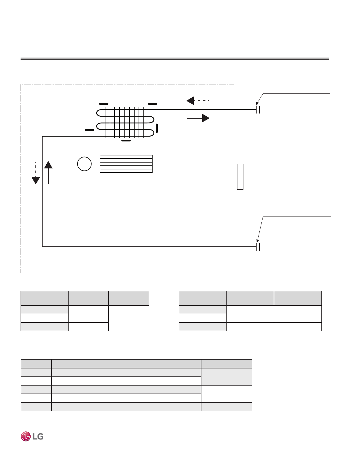
Table 8: Art Cool Mirror Indoor Unit Refrigerant Pipe Sizes.
Table 10: Art Cool Mirror Indoor Unit Thermistor Details.
Location Description (Based on Cooling Mode) IDU PCB Connector
Th1 Indoor Air Temperature Thermistor
CN-TH1
Th2 Evaporator Inlet Temperature Thermistor
Th3 Evaporator Middle Temperature Thermistor
CN-TH2
Th4 Evaporator Outlet Temperature Thermistor
Th5 Water Level Sensor (Optional) CN-TH3
ART COOL MIRROR INDOOR UNITS
Refrigerant Flow Diagram
Figure 8: Art Cool Mirror Indoor Unit Refrigerant Flow Diagram.
Indoor Unit Capacity
Vapor Line Size
(in., OD)
Liquid Line Size
(in., OD)
9,000 Btu/h
Ø3/8
Ø1/412,000 Btu/h
18,000 Btu/h Ø1/2
Indoor Unit Capacity
Vapor Line
Connection (in., OD)
Liquid Line
Connection (in., OD)
9,000 Btu/h
Ø3/8 Ø1/4
12,000 Btu/h
18,000 Btu/h Ø5/8 Ø3/8
Table 9: Art Cool Mirror Indoor Unit Refrigerant Pipe Connections
Vapor pipe connection port
(flare connection)
Liquid pipe connection port
(flare connection)
Cooling
Heating
Thermistor for
Indoor Air Temperature
Cross Flow Fan
M
Heat
Exchanger
Th1
Th2
Th3
Th5
Th4
ART COOL MIRROR | 19
Art Cool Mirror™
Due to our policy of continuous product innovation, some specications may change without notication.
©LG Electronics U.S.A., Inc., Englewood Cliffs, NJ. All rights reserved. “LG” is a registered trademark of LG Corp.
MULTI
F
MAX
MULTI
F
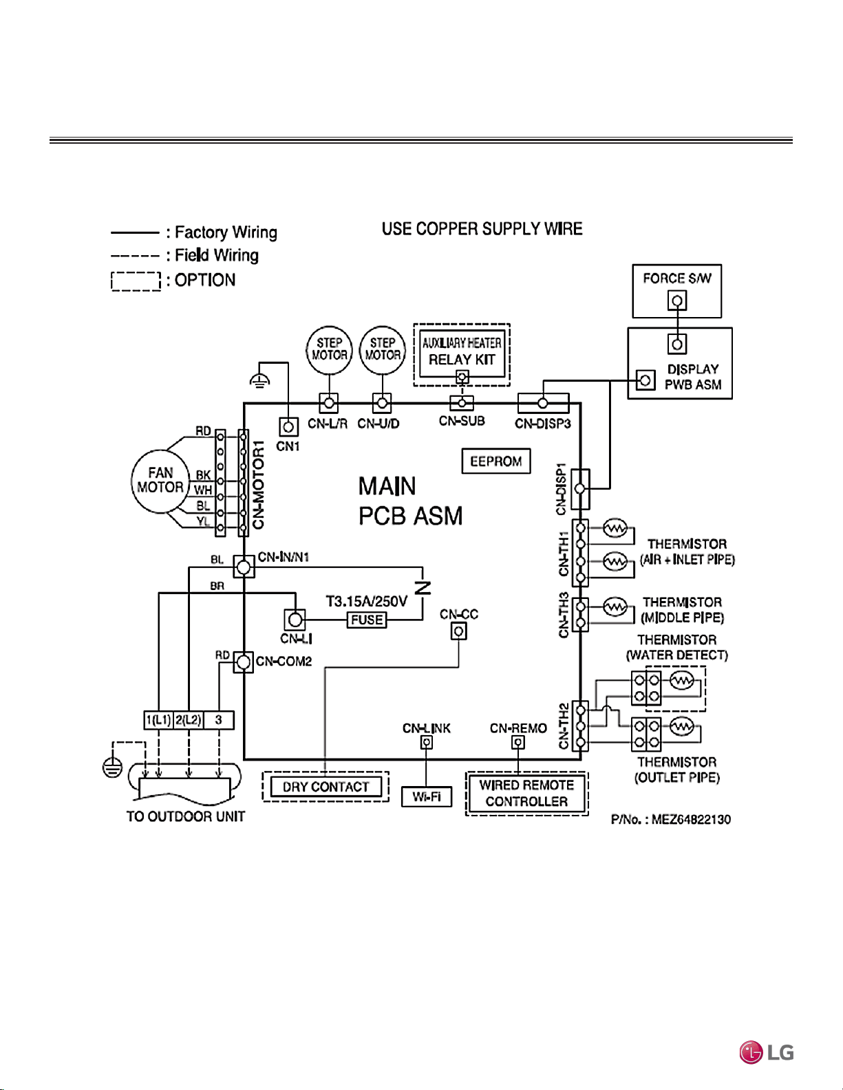
ART COOL MIRROR INDOOR UNITS
Wiring Diagram
Figure 9: Multi F Art Cool Mirror LAN090HSV5, LAN120HSV5, and LAN180HSV5 Indoor Units Wiring Diagram.
Due to our policy of continuous product innovation, some specications may change without notication.
©LG Electronics U.S.A., Inc., Englewood Cliffs, NJ. All rights reserved. “LG” is a registered trademark of LG Corp.
20 | ART COOL MIRROR
Multi F and Multi F MAX Indoor Unit Engineering Manual
MULTI
F
MAX
MULTI
F
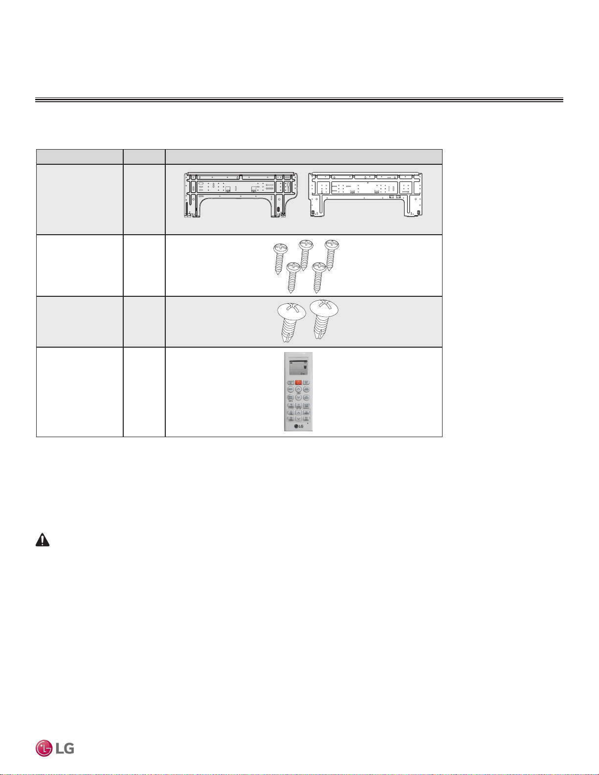
Factory Supplied Parts
Part Quantity Image
Installation Plate One (1)
Type “A” Screws Five (5)
Type “B” Screws
(M4 x 12L)
Two (2)
Wireless Handheld
Controller with Holder
AKB74955602
One (1)
Factory Supplied Materials
• Owner’s Manual
• Installation Manual
• Level
• Screwdriver
• Electric drill
• Hole core drill
• Flaring tool set
• Spanner (Half union)
• Thermometer
Factory Supplied Parts and Materials
ART COOL MIRROR INDOOR UNITS
7,000 ~ 15,000 Btu/h Indoor Units
18,000 and 24,000 Btu/h Indoor Units
Table 11: Parts Table.
Required Tools
LAN090HSV5 and LAN120HSV5 LAN180HSV5
WARNING
Installation work must be performed by trained personnel and in accordance with national wiring standards and all local or other applicable codes.
Improper installation can result in re, electric shock, physical injury, or death.
Note:
Read all instructions before installing this product. Become familiar with the unit’s components and connections, and the order of installation. Incorrect
installation can degrade or prevent proper operation.
ART COOL MIRROR | 21
Art Cool Mirror™
Due to our policy of continuous product innovation, some specications may change without notication.
©LG Electronics U.S.A., Inc., Englewood Cliffs, NJ. All rights reserved. “LG” is a registered trademark of LG Corp.
MULTI
F
MAX
MULTI
F
Mounting the Installation Plate
The mounting wall must be strong and solid enough to protect the unit from vibration.
• Mount the installation plate on the wall using the Type “A” screws. If mounting the unit on concrete, consider using anchor bolts.
• Always mount the installation plate horizontally. Measure the wall and mark the centerline using thread and a level.
ART COOL MIRROR INDOOR UNITS
Installation and Best Layout Practices
DANGER
To avoid the possibility of re, do not install the unit in an area where combustible gas will generate, ow, stagnate, or leak. Failure to do so will
cause serious bodily injury or death. Before beginning installation, read the safety summary at the beginning of this manual.
Select a location for installing the wall-mounted indoor unit (IDU) that meets the following conditions:
• Where there is enough structural strength to bear the weight of the unit
• Where air circulation will not be blocked
• Where noise prevention is taken into consideration
• Ensure there is sufficient space from the ceiling and floor
• Locate the indoor unit in a location where it can be easily connected to the outdoor unit/branch distribution unit
• Include space for drainage to ensure condensate flows properly out of the unit when it is in cooling mode
• Use a level indicator to ensure the unit is installed on a level plane
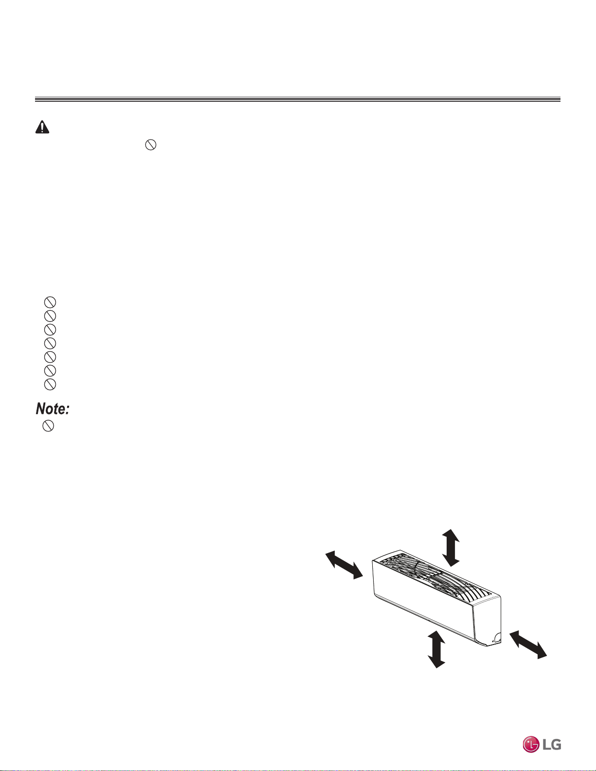
Note:
The unit will be damaged, will malfunction, and/or will not operate as designed if installed in any of the following conditions:
Do not install the unit where it will be subjected to direct thermal radiation from other heat sources.
Do not install the unit in an area where combustible gas will generate, flow, stagnate, or leak.
Do not install the unit in a location where acidic solution and spray (sulfur) are often used.
Do not use the unit in environments where oil, steam, or sulfuric gas are present.
Do not install additional ventilation products on the chassis of the unit.
Do not install the unit near high-frequency generator sources.
Do not install the unit near a doorway.
>4 inches
Recommended height
>6-1/2 feet from floor
>4 inches
≥5 inches
Figure 10:Minimum Clearance Requirements.
Installing in an Area Exposed to Unconditioned Air
In some installation applications, areas (floors, walls) in some rooms
will be exposed to unconditioned air (room will be above or next to
an unheated garage or storeroom). To countermeasure:
• Verify that carpet is or will be installed (carpet will increase the
temperature by three degrees).
• Add insulation between the floor joists.
• Install radiant heat or another type of heating system to the floor.
Required Clearances
Figure 10 shows required clearance distances around a typical
installed wall-mounted unit.
• Indoor units (IDUs) must not be placed in an environment where the IDUs will be exposed to harmful volatile organic compounds (VOCs)
or in environments where there is improper air make up or supply or inadequate ventilation. If there are concerns about VOCs in the envi-
ronment where the IDUs are installed, proper air make up or supply and/or adequate ventilation must be provided. Additionally, in buildings
where IDUs will be exposed to VOCs, consider a third party factory-applied epoxy coating to the fan coils for each IDU where the entire coil
is dipped, not sprayed.
• If the unit is installed near a body of water, the installation parts are at risk of corroding. Appropriate anti-corrosion methods must be taken
for the unit and all installation parts.
Due to our policy of continuous product innovation, some specications may change without notication.
©LG Electronics U.S.A., Inc., Englewood Cliffs, NJ. All rights reserved. “LG” is a registered trademark of LG Corp.
22 | ART COOL MIRROR
Multi F and Multi F MAX Indoor Unit Engineering Manual
MULTI
F
MAX
MULTI
F
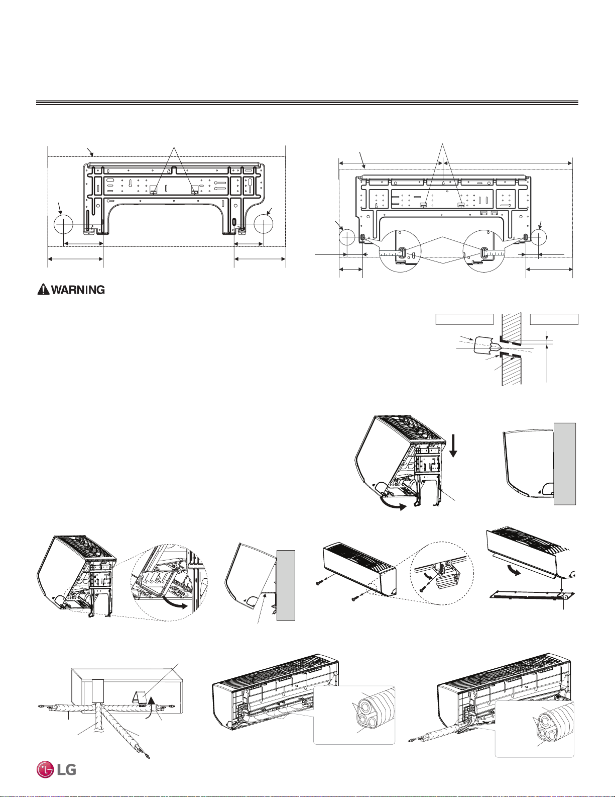
Ø2-3/4 inches
Ø2-3/4
inches
5-1/4 inches
3-3/4 inches
Right rear piping
Left rear piping
Installation Plate
Place a level on raised tab
Unit Outline
8-17/32 inches
6-7/8 inches
Figure 11:Installation Plate for LAN090HSV5 and LAN120HSV5 Units. Figure 12:Installation Plate for LAN180HSV5 Units.
Ø2-3/4 inches
Ø2-3/4 inches
2-23/32 inches
2-7/32 inches
Right rear
piping
Left rear
piping
Installation Plate
Measuring Tape
Measuring Tape Hanger
Place a level on raised tab
Unit Outline
8-5/32 inches
4-1/8 inches
18-1/8 inches 22-7/16 inches
ART COOL MIRROR INDOOR UNITS
Installation and Best Layout Practices
Hanging the Indoor Unit Chassis
1. Attach the three (3) hooks on the top of the indoor unit to the top edge of
the installation plate. Verify the hooks are properly attached to the instal-
lation plate by gently shaking the indoor unit from side to side.
2. Unlock the tubing clamp from the indoor unit frame. For easier access be-
tween the bottom of the indoor unit and the wall, prop the clamp between
the indoor unit frame and installation plate.
3. Remove the screw covers at the bottom of the indoor unit, unscrew the
two (2) screws, remove the frame cover, remove the piping connection
cover, and position the piping for installation (down, back, left, or right).
Installation plate
Figure 13:Locking the Indoor Unit onto the Installation Plate.
Tubing Clamp
Figure 14:Accessing the Back of the Indoor Unit.
Right
Tubing Clamp
Down
Left
Back
Frame Cover
Figure 15:Removing the Frame Cover.
Figure 16:Exterior Back View of Indoor Unit. Figure 17:Piping Installed to the Left.
Figure 18:Piping Installed to the Right.
Connecting
pipe
Tape
Drain hose
Connecting
pipe
Tape
Drain hose
Drilling Piping Hole in the Wall
Use caution when drilling holes through walls. Drilling into power wiring in the wall can cause serious
bodily injury or death.
Follow the left or right piping clearance recommendations.
1. Using a 2-5/8 (ø 65mm) inch hole core drill bit, drill a hole at either the right or left side of the
wall mounting. The hole must slant 3/16” to 5/16” from level (upward on the indoor unit side and
downward on the outdoor unit side).
2. Finish off the newly drilled hole as shown with bushing and sleeve covering. Sleeve and bush-
ing prevents damage to the tubing/bundling of the piping.
(3/16"~5/16")
Indoor
WALL
Outdoor
Bushing
Core Drill
Sleeve
Figure 19:Drilling Piping Hole
ART COOL MIRROR | 23
Art Cool Mirror™
Due to our policy of continuous product innovation, some specications may change without notication.
©LG Electronics U.S.A., Inc., Englewood Cliffs, NJ. All rights reserved. “LG” is a registered trademark of LG Corp.
MULTI
F
MAX
MULTI
F
ART COOL MIRROR INDOOR UNITS
Installation and Best Layout Practices
Power Wiring / Communications Cable Guidelines
• Follow manufacturer’s circuit diagrams in the technical manuals.
• Confirm power source specifications.
• Confirm that the electrical capacity is sufficient.
• Starting current must be maintained ±10 percent of the rated current marked on the outdoor unit name plate.
• Confirm cable thickness specifications.
• It is required that a circuit breaker is installed, especially if conditions could become wet or moist.
• Include a disconnect in the power wiring system, add an air gap contact separation of at least 1/8 inch in each active (phase) conductor.
• Loose wiring will cause unit to malfunction, overheat, and catch fire, resulting in severe injury or death.
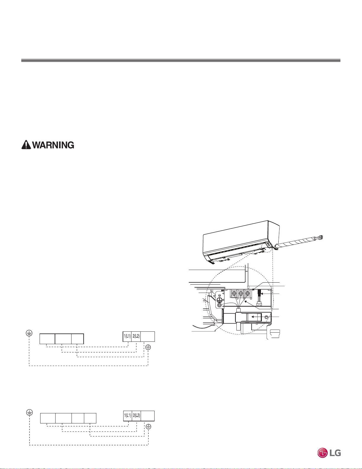
1. Insert the power wiring/communications cable from the outdoor
unit or branch distribution unit (Multi F MAX systems only)
through the bottom of the indoor unit.
2. Connect each wire to its appropriate terminal on the indoor unit
control board. Verify that the color and terminal numbers from
the outdoor unit or branch distribution unit (Multi F MAX systems
only) wiring match the color and terminal numbers on the indoor
unit.
3. Secure the power wiring/communications cable with the cable
restraint.
Terminal block
Power wiring /
communications cable
Wired Remote Controlle
r
Terminal (Optional)
Cable restraint
Connecting the Power Wiring and Communications Cable
Figure 20:Connecting the Power Wiring / Communications Cable.
Figure 21:Simplied View of Indoor Unit to Outdoor Unit / Branch
Distribution Unit Terminal Connections—LAN090HSV5 and
LAN120HSV5 models.
Figure 22:Simplied View of Indoor Unit to Outdoor Unit / Branch
Distribution Unit Terminal Connections—LAN180HSV5 models.
Indoor Unit Terminal Block
GND
Outdoor Unit Terminal Block or
Branch Distribution Unit Terminal Block
(Multi F MAX Systems Only)
GND
GRN / YLW
BR
BL
RD
3 or S
32(L2)1(L1)
Indoor Unit Terminal Block
1(L1 )2(L2)
GND
Outdoor Unit Terminal Block or
Branch Distribution Unit Terminal Block
(Multi F MAX Systems Only)
GND
GRN / YLW
BR
BL
RD
3
3 or S
Note:
• Terminal screws will become loose during transport. Properly tighten the terminal connections during installation.
A voltage drop will cause the following problems:
• Magnetic switch vibration, fuse breaks, or disturbance to the normal function of an overload protection device.
• Compressor will not receive the proper starting current.
Due to our policy of continuous product innovation, some specications may change without notication.
©LG Electronics U.S.A., Inc., Englewood Cliffs, NJ. All rights reserved. “LG” is a registered trademark of LG Corp.
24 | ART COOL MIRROR
Multi F and Multi F MAX Indoor Unit Engineering Manual
MULTI
F
MAX
MULTI
F
ART COOL MIRROR INDOOR UNITS
Installation and Best Layout Practices
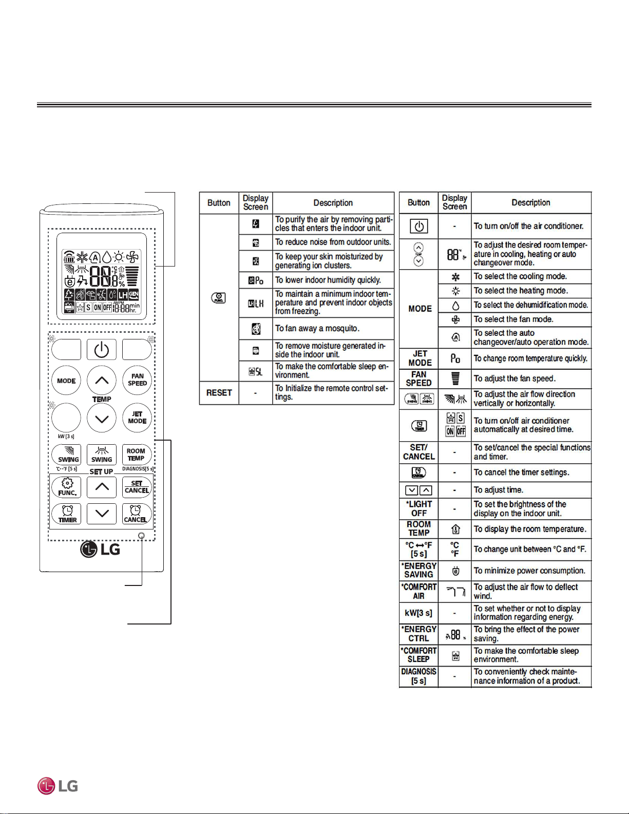
Wireless Handheld Controller
Table 12: AKB74955602 Wireless Controller Functions.Figure 23:AKB74955602 Wireless Controller.
Screen Display
Buttons
*
*
*
RESET
ART COOL MIRROR | 25
Art Cool Mirror™
Due to our policy of continuous product innovation, some specications may change without notication.
©LG Electronics U.S.A., Inc., Englewood Cliffs, NJ. All rights reserved. “LG” is a registered trademark of LG Corp.
MULTI
F
MAX
MULTI
F
ART COOL MIRROR INDOOR UNITS
Installation and Best Layout Practices
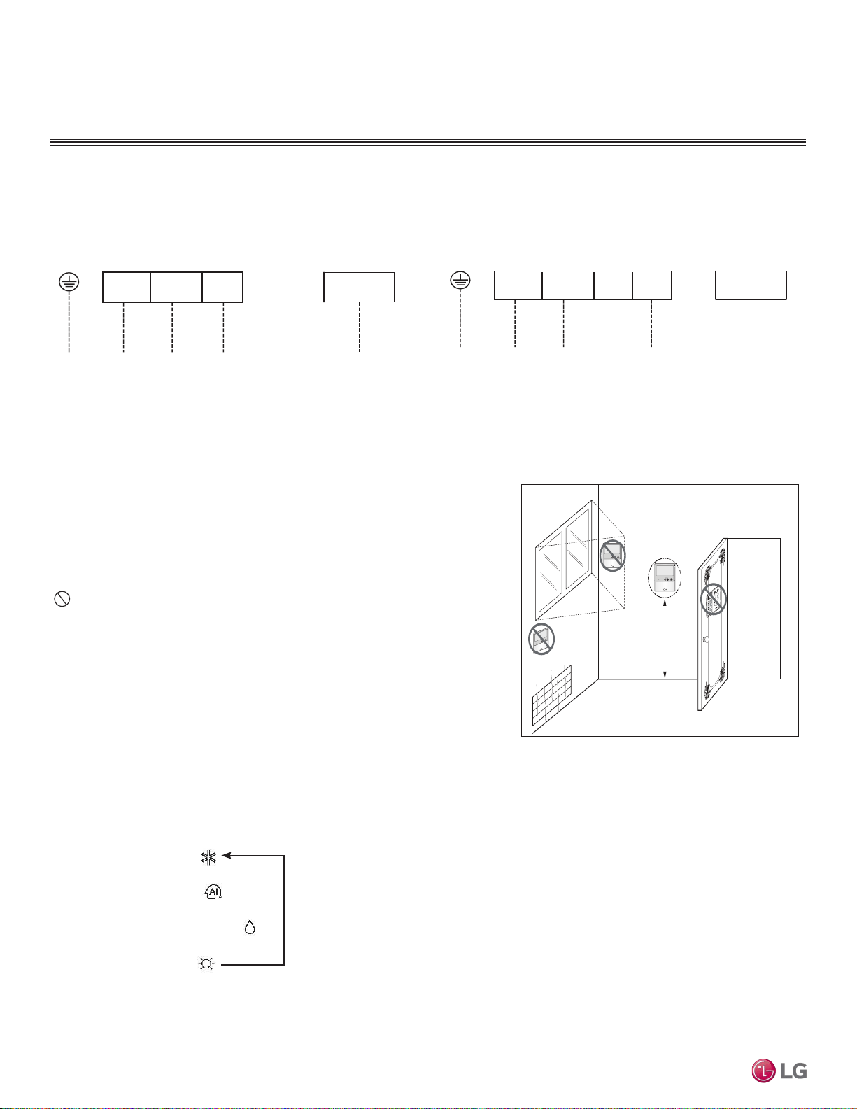
Operation Mode Sequence
Cooling Mode
↓
Auto Operation
↓
Dehumidification Mode
↓
Heating Mode
Wired controllers include a sensor to detect room temperature. To maintain comfort
levels in the conditioned space, the wired controller must be installed in a location
away from direct sunlight, high humidity, and where it could be directly exposed to
cold air. Controller must be installed four (4) to five (5) feet above the floor where its
LED display can be read easily, in an area with good air circulation, and where it can
detect an average room temperature.
Do not install the wired controller near or in:
• Drafts or dead spots behind doors and in corners
• Hot or cold air from ducts
• Radiant heat from the sun or appliances
• Concealed pipes and chimneys
• An area where temperatures are uncontrolled, such as an outside wall
Figure 24:Wired Controller Connection on the Indoor Unit Terminal
Block—LAN090HSV5 and LAN120HSV5 models.
Indoor Unit Terminal Block
1(L1 )2(L2)
GND
GRN / YLW
BR
BL
RD
CN-REMO
To Outdoor Unit or Branch Distribution Unit
(Multi F MAX Systems Only)
To Wired Controller
3
Figure 25:Wired Controller Connection on the Indoor Unit Terminal
Block—LAN180HSV5 models.
Figure 26:Proper Location for the Wired Controller.
Indoor Unit Terminal Block
1(L1 )2(L2)
GND
GRN / YLW
BR
BL
RD
CN-REMO
To Outdoor Unit or Branch Distribution Unit
(Multi F MAX Systems Only)
To Wired Controller
3
Wired Controller Connections
Wired Controller Placement
4 to 5 feet
above the floor
NO
NO
NO
YES
Remote Controller
TEMP
Remote Controller
TEMP
Re
m
ot
e Co
nt
r
ol
l
er
TEMP
Due to our policy of continuous product innovation, some specications may change without notication.
©LG Electronics U.S.A., Inc., Englewood Cliffs, NJ. All rights reserved. “LG” is a registered trademark of LG Corp.
26 | ART COOL MIRROR
Multi F and Multi F MAX Indoor Unit Engineering Manual
MULTI
F
MAX
MULTI
F
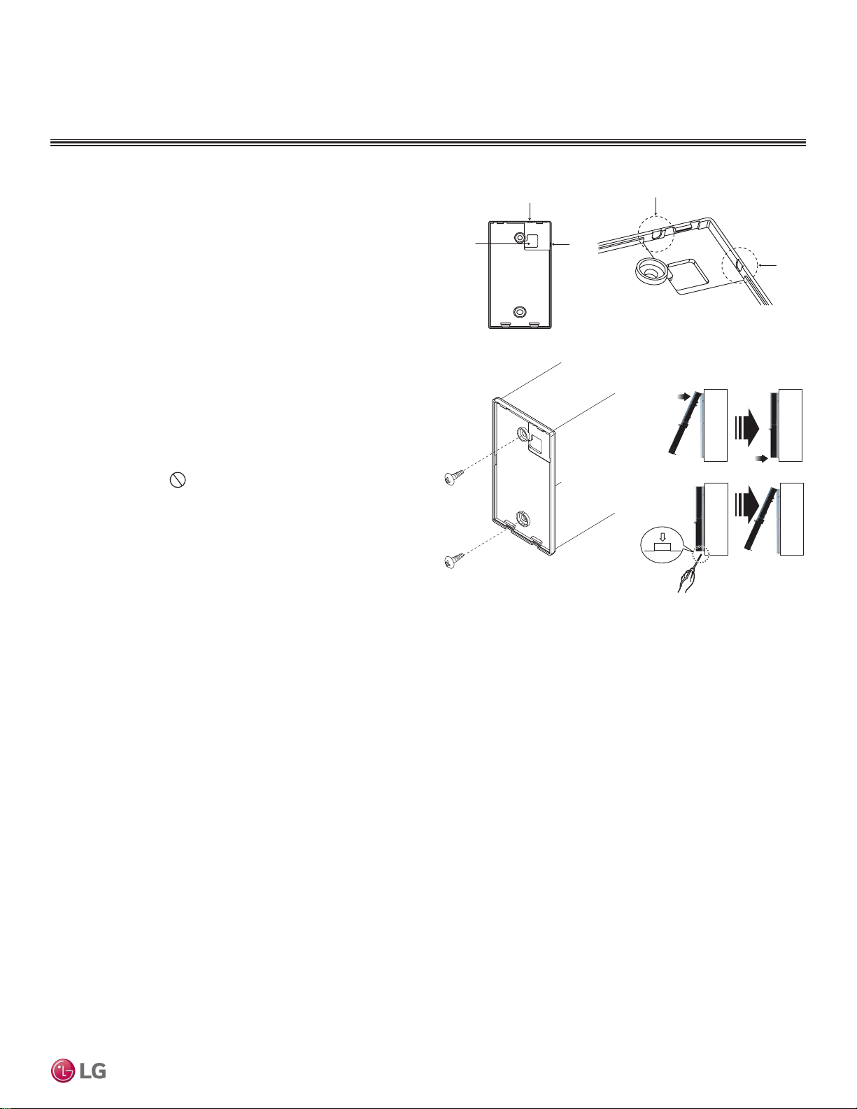
Figure 27:Removing the Cable Guide Grooves.
ART COOL MIRROR INDOOR UNITS
Installation and Best Layout Practices
Assigning the Thermistor for Temperature Detection
Each indoor unit includes a return air thermistor assigned to sense the temperature. If a wired controller is installed, there is a choice of
sensing temperature with either the indoor unit return air thermistor or the thermistor in the wired controller. It is also an option to set both
thermistors to sense temperature so that indoor unit bases its operation on the first thermistor to reach the designated temperature differen-
tial. For applicable indoor units, an optional Remote Temperature Sensor can be used in lieu of the return air thermistor—either alone or in
conjunction with a wired controller thermistor as previously described.
Hanging the Wired Controller
1. The controller wiring/cable can be installed in one of three direc-
tions: top, back, or on the right side. If top or right side installation
is desired, remove cable guide grooves on the controller, and
then position wiring/cable on applicable side.
2. Choose and mark the area of installation, and then screw the wall
plate into place (using the provided parts). Install the controller
wall plate to fit the electrical box if one is present. Ensure that no
gaps exist between the wall plate and the wall itself.
3. Arrange wiring/cables so as not to interfere with the controller
circuitry. Position the wired controller on the wall plate. Snap into
place by pressing the bottom part of the wired controller onto
the wall plate. Make sure that no gaps exist between the wired
controller and the wall plate on all sides.
4. To remove wired controller from the wall plate, insert a screw-
driver into the two holes at the bottom. Twist screwdriver to
release controller.
Do not damage the controller components
when removing.
Back
Top
Top
Right
Side
Right
Side
Wall Wall
Wall Wall
Installing the Controller
Removing the Controller
Figure 28:Attaching the Wall Plate. Figure 29:Installing/Removing the
Controller.
ART COOL MIRROR | 27
Art Cool Mirror™
Due to our policy of continuous product innovation, some specications may change without notication.
©LG Electronics U.S.A., Inc., Englewood Cliffs, NJ. All rights reserved. “LG” is a registered trademark of LG Corp.
MULTI
F
MAX
MULTI
F

“Mechanical Specifications” on page 29
“General Data / Specifications” on page 30
“Dimensions” on page 31
“Cooling Capacity Table” on page 32
“Heating Capacity Table” on page 33
“Acoustic Data” on page 34
“Air Velocity and Temperature Distribution” on page 35
“Refrigerant Flow Diagram” on page 36
“Wiring Diagram” on page 37
“Factory Supplied Parts and Materials” on page 38
“Installation and Best Layout Practices” on page 39
ART COO
L
™
GALLERY
INDOOR UNIT DATA
ART COOL Gallery Indoor Units
General
All LG indoor units are factory assembled, wired, piped, and pro-
vided with a control circuit board, fan, and motor. Art Cool Gallery
indoor units have a sound rating no higher than 42 dB(A) as tested
per KSA0701 ISO Standard 3745.
Coil
Indoor unit coils are comprised of a minimum of two rows of
aluminum fins mechanically bonded to copper tubing. The coils are
pressure tested at the factory. Each unit is provided with a factory
installed condensate drain pan below the coil.
Refrigerant System
System is designed for use with R410A refrigerant. The refrigeration
circuit is pressure-tested at the factory and shipped with a holding
charge of helium gas. Refrigerant pipe connections are 45° flare.
All refrigerant lines from the outdoor unit to the indoor units must be
field insulated.
Electrical
Each indoor unit is designed to operate using 208–230/60/1 power
with voltage variances of ±10%.
Casing
Units are designed to mount on a vertical surface, and are shipped
with a separate back plate that secures the unit to the wall, protrud-
ing no more than six (6) inches. Unit is designed so that refrigerant
piping can be installed in one of four different directions.
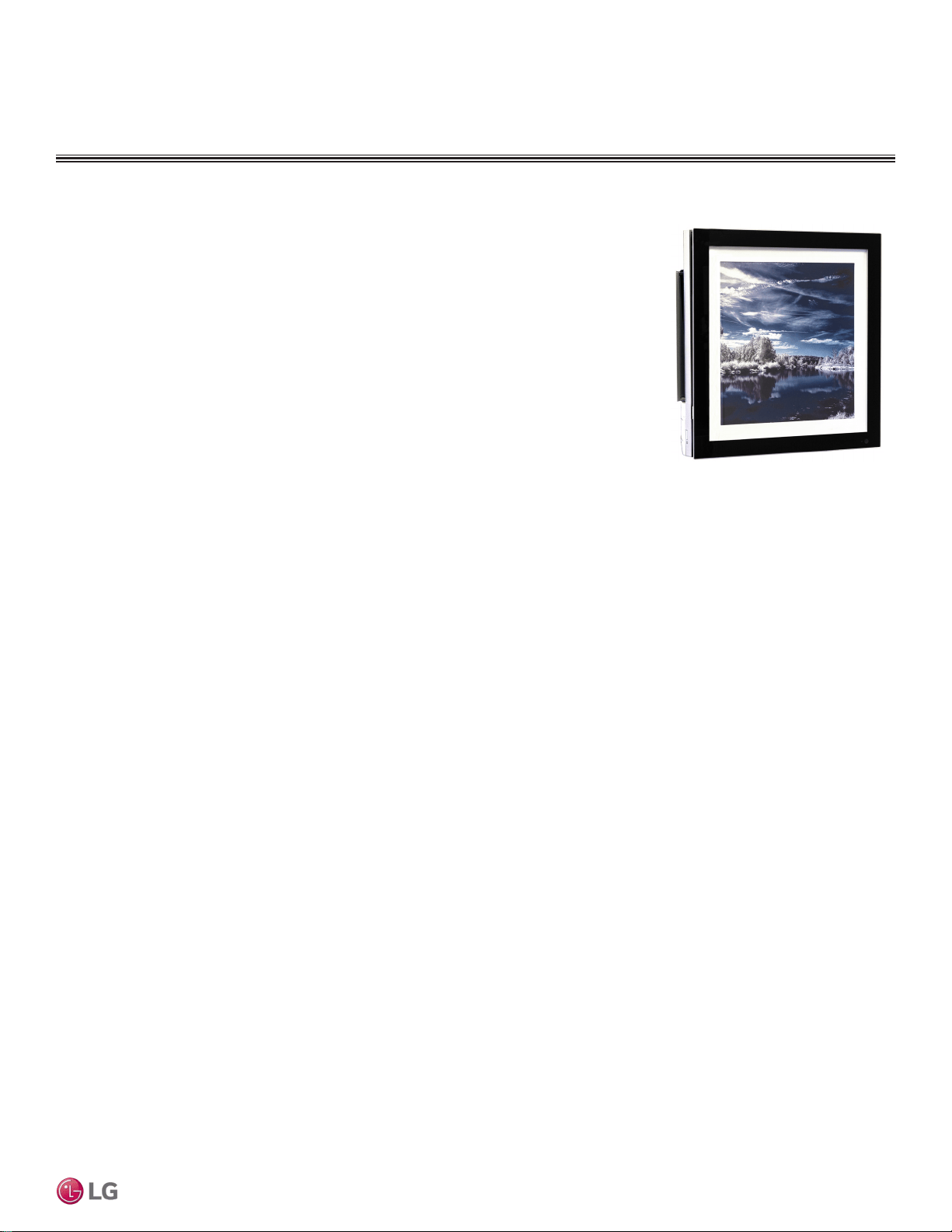
Cases / Finishes
The Art Cool Gallery unit has a frame that can accommodate a 20" x
20" photograph, picture or artwork. Unit casing has a gray finish and
is manufactured of heavy-duty acrylonitrile butadiene styrene (ABS)
and high impact polystyrene (HIPS) plastic.
Fan Assembly and Control
The unit has a single, direct-drive, crossflow fan made of high
strength ABS plastic. The fan motor is brushless digitally controlled
(BLDC) with permanently lubricated and sealed ball bearings. The
fan/motor assembly is mounted on vibration attenuating rubber
grommets. Fan speed is controlled using a microprocessor-based
direct digitally controlled algorithm that provides pre-programmed,
field-selectable fixed or auto fan speeds in the Heating and Cooling
modes. For Art Cool Gallery units, the indoor fan has Low, Med,
High, Power Cool and Auto settings for Cooling mode; and has Low,
Med, High, and Auto settings for Heating mode. The Auto setting
adjusts the fan speed based on the difference between the controller
setpoint and space temperature. Also, the separate Chaos setting
provides a simultaneous and random change in fan speed and flow
direction at the discharge,
simulating a natural outdoor
breeze.
Air Filter
Return air is filtered with a
factory-supplied, removable,
washable pre-filter. Filter
access is from the front of
the unit without the use of
tools.
Airflow Guide Vanes
Motorized oscillating guide
vanes are factory installed,
and allows the ability to
control the direction of
airflow from side to side. A
motorized air sweep louver provides an automatic change in airflow
by directing the air up and down to provide uniform air distribution.
Microprocessor Control
The indoor unit is provided with an integrated control panel to
communicate with the outdoor unit. All unit operation parameters are
stored in non-volatile memory resident on the unit microprocessor.
The microprocessor controls space temperature through using the
value provided by the temperature sensor within the indoor unit.
The microprocessor control will activate indoor unit operation when
the indoor room temperature falls below or rises above a setpoint
temperature, at which point, a signal is sent to the outdoor unit to
begin the appropriate mode. The microprocessor will also provide
self-diagnostics and auto restart functions. A field-supplied four-
wire power / communications cable must be installed to connect the
indoor unit(s) to the outdoor unit.
Controls
The indoor unit casing has a factory-standard, integral infrared
sensor designed to communicate with the supplied LG wireless
handheld remote controller. An optional LG supplied wired controller
is available as an additional accessory. Communication between the
indoor units and the outdoor unit is accomplished through 14 AWG,
four-core, stranded and shielded power / communication cable.
Condensate
The unit is designed for gravity draining of condensate and includes
a flexible drain hose capable of installation in one of two directions.
Unit includes a connection that is compatible with the AquaGuard
®
AG-9300-LG condensate sensor.
ART COOL GALLERY INDOOR UNITS
Mechanical Specications and Features
• Inverter (Variable speed fan)
• Chaos swing
• Jet cool
• Group control
• Self-cleaning indoor coil
• Auto operation / auto restart operation
• 24-Hour on/off timer
• Wireless LCD remote control included;
wired thermostat available (sold separately)
Features
Figure 30: Multi F Art Cool Gallery
Indoor Unit.
ART COOL GALLERY™ | 29
Art Cool Gallery™
Due to our policy of continuous product innovation, some specications may change without notication.
©LG Electronics U.S.A., Inc., Englewood Cliffs, NJ. All rights reserved. “LG” is a registered trademark of LG Corp.
MULTI
F
MAX
MULTI
F
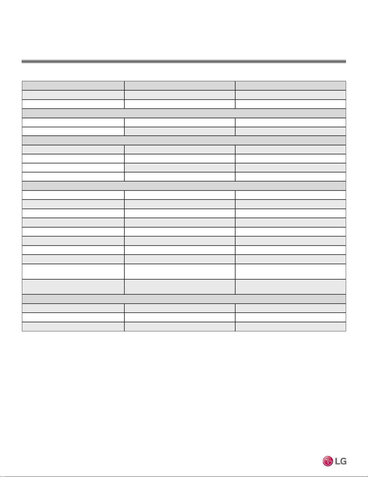
Model Name LMAN097HVP LMAN127HVP
Nominal Cooling Capacity (Btu/h)
1
9,000 11,200
Nominal Heating Capacity (Btu/h)
1
10,400 13,300
Operating Range
Cooling (°F WB)
57-77 57-77
Heating (°F DB)
59-81 59-81
Fan
Type
Turbo Turbo
Motor Output (W) x Qty.
24 x 1 24 x 1
Motor/Drive
Brushless Digitally Controlled / Direct Brushless Digitally Controlled / Direct
Airflow Rate CFM (H/M/L)
272 / 208 / 155 314 / 258 / 198
Unit Data
Refrigerant Type
2
R410A R410A
Refrigerant Control
EEV EEV
Power Supply V, Ø, Hz
3
208-230, 1, 60 208-230, 1, 60
Rated Amps (A)
0.2 0.2
Sound Pressure Level dB(A) (H/M/L)
4
39 / 35 / 31 42 / 38 / 34
Dimensions (W x H x D, in.)
23-5/8 x 23-5/8 x 5-25/32 23-5/8 x 23-5/8 x 5-25/32
Net Unit Weight (lbs.)
32 32
Shipping Weight (lbs.)
37 37
Power Wiring / Communications Cable
(No. x AWG)
5
4 x 14 4 x 14
Heat Exchanger
(Row x Column x Fin / inch) x Number
(2 x 20 x 21) x 1 (2 x 20 x 21) x 1
Piping
Liquid (in.)
1/4 1/4
Vapor (in.)
3/8 3/8
Drain O.D. / I.D. (in.)
27/32, 5/8 27/32, 5/8
1
Nominal capacity is rated 0 ft. above sea level with corresponding refrigerant piping length in
accordance with standard length of each outdoor unit and a 0 ft. level difference between outdoor and
indoor units. All capacities are net with a combination ratio between 95 – 105%.
Nominal cooling capacity rating obtained with air entering the indoor unit at 80ºF dry bulb (DB) and 67ºF
wet bulb (WB) and outdoor ambient conditions of 95ºF dry bulb (DB) and 75ºF wet bulb (WB).
Nominal heating capacity rating obtained with air entering the indoor unit at 70ºF dry bulb (DB) and 60ºF
wet bulb (WB) and outdoor ambient conditions of 47ºF dry bulb (DB) and 43ºF wet bulb (WB).
2
This unit comes with a dry helium charge.
3
Acceptable operating voltage: 187V-253V.
4
Sound pressure levels are tested in an anechoic chamber under ISO Standard 3745 and are the
same in both cooling and heating mode. These values can increase due to ambient conditions during
operation.
5
All power wiring / communications cable to the IDUs be minimum 14 AWG, 4-conductor, stranded,
shielded or unshielded (if shielded, must be grounded to chassis at ODU only) and must comply with
applicable local and national codes.
ART COOL GALLERY INDOOR UNITS
General Data / Specications
Table 13: Multi F Art Cool Gallery Indoor Unit General Data.
Due to our policy of continuous product innovation, some specications may change without notication.
©LG Electronics U.S.A., Inc., Englewood Cliffs, NJ. All rights reserved. “LG” is a registered trademark of LG Corp.
30 | ART COOL GALLERY™
Multi F and Multi F MAX Indoor Unit Engineering Manual
MULTI
F
MAX
MULTI
F
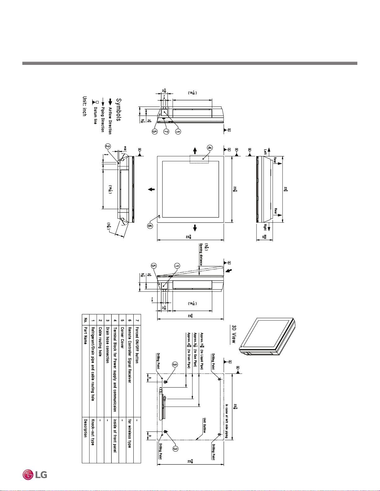
ART COOL GALLERY INDOOR UNITS
Dimensions
Figure 31: LMAN097HVP and LMAN127HVP Dimensions.
Supply Air Vane
Return Air Inlet
Supply Air Vane
Supply Air
Supply
Air
Supply
Air
Discharge Air Grille
Supply Air Vane
ART COOL GALLERY™ | 31
Art Cool Gallery™
Due to our policy of continuous product innovation, some specications may change without notication.
©LG Electronics U.S.A., Inc., Englewood Cliffs, NJ. All rights reserved. “LG” is a registered trademark of LG Corp.
MULTI
F
MAX
MULTI
F

Cooling Capacity Table
ART COOL GALLERY INDOOR UNITS
Table 14: Multi F Art Cool Gallery Indoor Units Cooling Capacity Table.
Model No. /
Nominal Capacity
of Indoor Unit
(Btu/h)
Outdoor Air
Temp.
(°F DB)
Indoor Air Temp. °F DB / °F WB
68 / 57 73 / 61 77 / 64 80 / 67 86 / 72 90 / 75
TC SHC TC SHC TC SHC TC SHC TC SHC TC SHC
LMAN097HVP
9,000
14 8.82 5.68 9.37 6.00 9.92 5.81 10.31 5.93 11.01 5.98 11.56 6.09
20 8.82 5.72 9.36 6.04 9.91 5.85 10.31 5.98 11.01 6.03 11.55 6.14
25 8.81 5.77 9.36 6.09 9.90 5.90 10.30 6.02 11.00 6.07 11.54 6.19
30 8.80 5.81 9.35 6.14 9.90 5.94 10.29 6.07 10.99 6.12 11.54 6.23
35 8.80 5.85 9.34 6.18 9.89 5.99 10.28 6.11 10.98 6.17 11.53 6.28
40 8.79 5.90 9.33 6.23 9.88 6.03 10.27 6.16 10.97 6.21 11.52 6.33
45 8.78 5.94 9.33 6.28 9.87 6.08 10.27 6.21 10.96 6.26 11.51 6.38
50 8.78 5.99 9.32 6.32 9.87 6.12 10.26 6.25 10.96 6.30 11.50 6.42
55 8.77 6.03 9.31 6.37 9.86 6.17 10.25 6.30 10.95 6.35 11.49 6.47
60 8.76 6.07 9.31 6.42 9.85 6.21 10.24 6.34 10.94 6.40 11.48 6.52
65 8.76 6.12 9.30 6.46 9.84 6.26 10.24 6.39 10.93 6.44 11.47 6.56
70 8.75 6.16 9.29 6.51 9.84 6.30 10.23 6.43 10.92 6.49 11.47 6.61
75 8.54 6.06 9.08 6.41 9.62 6.21 10.01 6.35 10.71 6.41 11.25 6.54
80 8.33 5.96 8.87 6.31 9.41 6.12 9.80 6.26 10.49 6.33 11.03 6.46
85 8.12 5.85 8.66 6.20 9.20 6.03 9.59 6.17 10.28 6.24 10.82 6.38
90 7.91 5.74 8.45 6.09 8.99 5.93 9.37 6.07 10.06 6.16 10.60 6.30
95 7.68 5.68 8.22 6.04 8.75 5.88 9.00 5.94 9.83 6.12 10.36 6.27
100 7.50 5.52 8.03 5.89 8.57 5.74 8.88 5.85 9.64 5.99 10.17 6.14
105 7.31 5.37 7.84 5.73 8.38 5.60 8.77 5.76 9.45 5.86 9.99 6.01
110 7.12 5.19 7.66 5.55 8.19 5.43 8.58 5.58 9.26 5.69 9.80 5.85
115 6.94 5.03 7.47 5.39 8.01 5.29 8.39 5.44 9.08 5.56 9.61 5.71
118 6.82 5.00 7.36 5.36 7.89 5.26 8.28 5.42 8.96 5.54 9.50 5.70
122 6.79 4.98 7.32 5.35 7.86 5.25 8.24 5.41 8.93 5.53 9.46 5.69
LMAN127HVP
12,000
14 10.98 7.06 11.66 7.46 12.34 7.22 12.84 7.38 13.71 7.44 14.39 7.58
20 10.97 7.12 11.65 7.52 12.33 7.28 12.83 7.43 13.70 7.50 14.38 7.64
25 10.96 7.17 11.64 7.58 12.32 7.34 12.82 7.49 13.69 7.55 14.37 7.70
30 10.95 7.23 11.63 7.64 12.31 7.39 12.81 7.55 13.68 7.61 14.36 7.76
35 10.95 7.28 11.63 7.69 12.31 7.45 12.80 7.61 13.66 7.67 14.34 7.82
40 10.94 7.34 11.62 7.75 12.30 7.51 12.79 7.66 13.65 7.73 14.33 7.87
45 10.93 7.39 11.61 7.81 12.29 7.56 12.78 7.72 13.64 7.79 14.32 7.93
50 10.92 7.45 11.60 7.87 12.28 7.62 12.77 7.78 13.63 7.84 14.31 7.99
55 10.91 7.50 11.59 7.92 12.27 7.67 12.76 7.83 13.62 7.90 14.30 8.05
60 10.90 7.56 11.58 7.98 12.26 7.73 12.75 7.89 13.61 7.96 14.29 8.11
65 10.90 7.61 11.57 8.04 12.25 7.78 12.74 7.95 13.60 8.02 14.28 8.17
70 10.89 7.67 11.56 8.10 12.24 7.84 12.73 8.01 13.59 8.07 14.27 8.23
75 10.63 7.54 11.30 7.97 11.97 7.73 12.46 7.90 13.32 7.97 14.00 8.13
80 10.36 7.41 11.04 7.85 11.71 7.62 12.19 7.79 13.05 7.87 13.73 8.04
85 10.10 7.27 10.77 7.72 11.45 7.50 11.93 7.67 12.79 7.77 13.46 7.94
90 9.84 7.14 10.51 7.58 11.18 7.38 11.67 7.56 12.52 7.66 13.19 7.83
95 9.56 7.06 10.23 7.51 10.89 7.32 11.20 7.39 12.23 7.62 12.89 7.80
100 9.33 6.87 10.00 7.32 10.66 7.15 11.05 7.28 11.99 7.45 12.66 7.64
105 9.10 6.68 9.76 7.13 10.43 6.97 10.91 7.16 11.76 7.29 12.43 7.48
110 8.86 6.46 9.53 6.90 10.20 6.76 10.68 6.95 11.53 7.08 12.19 7.27
115 8.63 6.26 9.30 6.71 9.96 6.58 10.44 6.77 11.30 6.91 11.96 7.11
118 8.49 6.22 9.16 6.67 9.82 6.54 10.30 6.74 11.16 6.89 11.82 7.09
122 8.44 6.20 9.11 6.65 9.78 6.53 10.26 6.73 11.11 6.88 11.78 7.08
TC = Total Capacity (kBtu/h).
SHC: Sensible Heat Capacity (kBtu/h).
Nominal capacity as rated 0 ft. above sea level and a 0 ft. level difference between outdoor and indoor units. Corresponding refrigerant piping length is accordance with standard length of each outdoor unit.
Nominal cooling capacity rating obtained with air entering the indoor unit at 80ºF dry bulb (DB) and 67ºF wet bulb (WB), and outdoor ambient conditions of 95ºF dry bulb (DB) and 75ºF wet bulb (WB).
The shaded table columns and rows indicate reference data. When operating at this temperature, these values can be different if the system is not running consistently.
Due to our policy of continuous product innovation, some specications may change without notication.
©LG Electronics U.S.A., Inc., Englewood Cliffs, NJ. All rights reserved. “LG” is a registered trademark of LG Corp.
32 | ART COOL GALLERY™
Multi F and Multi F MAX Indoor Unit Engineering Manual
MULTI
F
MAX
MULTI
F
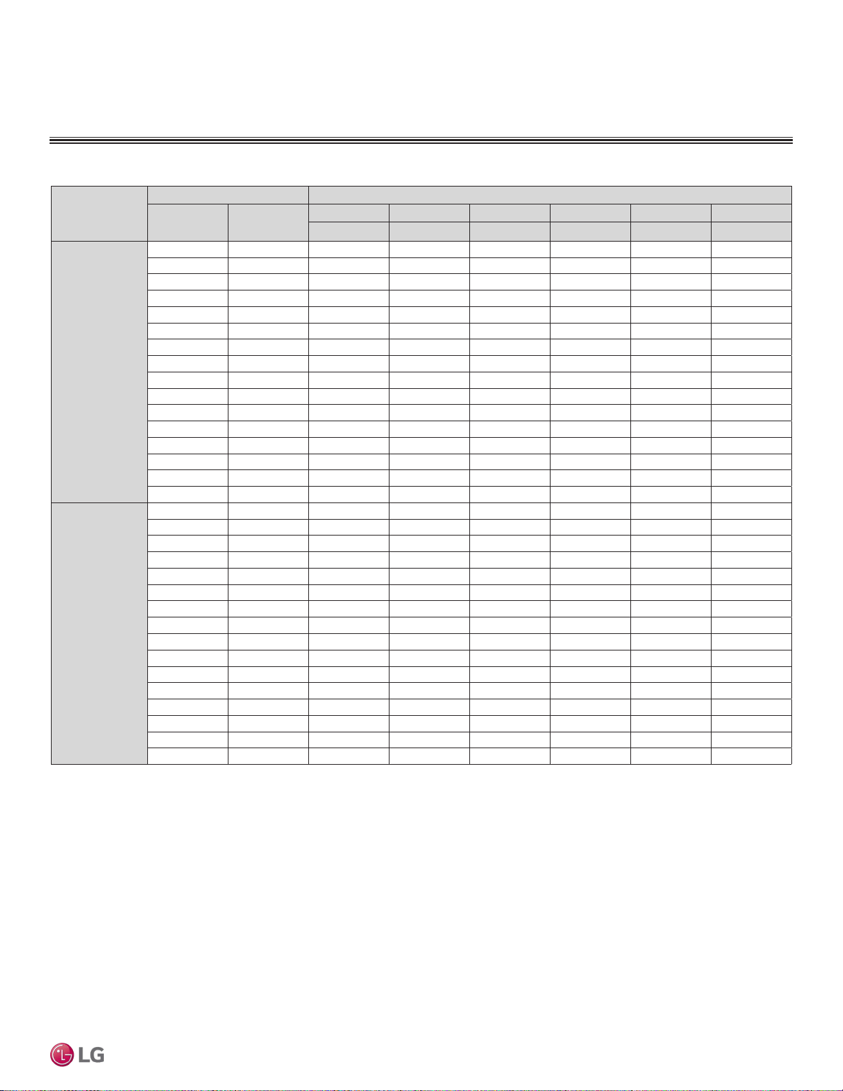
Heating Capacity Table
ART COOL GALLERY INDOOR UNITS
Table 15: Multi F Art Cool Gallery Indoor Units Heating Capacity Table.
Model No. /
Nominal Capacity
of Indoor Unit
(Btu/h)
Outdoor Air Temp. Indoor Air Temp. °F DB
°F DB °F WB
61 64 68 70 72 75
TC TC TC TC TC TC
LMAN097HVP
9,000
0 -0.4 5.35 5.28 5.23 5.20 5.12 4.90
5 4.5 6.03 5.95 5.90 5.88 5.80 5.58
10 9 6.71 6.63 6.58 6.56 6.48 6.26
17 15 7.61 7.54 7.49 7.46 7.39 7.14
20 19 7.95 7.88 7.83 7.80 7.72 7.46
25 23 8.52 8.44 8.39 8.37 8.29 7.99
30 28 9.01 8.93 8.88 8.86 8.78 8.52
35 32 9.50 9.42 9.37 9.34 9.27 9.04
40 36 9.94 9.86 9.81 9.78 9.71 9.48
45 41 10.37 10.30 10.25 10.22 10.15 9.92
47 43 10.55 10.48 10.43 10.40 10.32 10.10
50 46 10.72 10.64 10.59 10.57 10.49 10.24
55 51 11.00 10.93 10.88 10.85 10.78 10.48
60 56 11.00 10.93 10.88 10.85 10.78 10.52
63 59 11.00 10.93 10.88 10.85 10.78 10.55
68 64 11.00 10.93 10.88 10.85 10.78 10.60
LMAN127HVP
12,000
0 -0.4 6.84 6.75 6.68 6.65 6.55 6.26
5 4.5 7.71 7.61 7.55 7.52 7.42 7.13
10 9 8.58 8.48 8.42 8.38 8.29 8.00
17 15 9.73 9.64 9.57 9.54 9.44 9.14
20 19 10.17 10.07 10.01 9.98 9.88 9.54
25 23 10.89 10.79 10.73 10.70 10.60 10.22
30 28 11.52 11.42 11.36 11.32 11.23 10.89
35 32 12.14 12.05 11.98 11.95 11.85 11.57
40 36 12.71 12.61 12.55 12.51 12.42 12.13
45 41 13.27 13.17 13.11 13.08 12.98 12.69
47 43 13.49 13.40 13.33 13.30 13.20 12.91
50 46 13.71 13.61 13.55 13.52 13.42 13.10
55 51 14.07 13.97 13.91 13.88 13.78 13.40
60 56 14.07 13.97 13.91 13.88 13.78 13.46
63 59 14.07 13.97 13.91 13.88 13.78 13.49
68 64 14.07 13.97 13.91 13.88 13.78 13.55
TC = Total Capacity (kBtu/h).
Nominal capacity as rated 0 ft. above sea level and a 0 ft. level difference between outdoor and indoor units. Corresponding refrigerant piping length is accordance with standard length of each outdoor unit.
Nominal heating capacity rating obtained with air entering the indoor unit at 70ºF dry bulb (DB) and 60ºF wet bulb (WB), and outdoor ambient conditions of 47ºF dry bulb (DB) and 43ºF wet bulb (WB).
ART COOL GALLERY™ | 33
Art Cool Gallery™
Due to our policy of continuous product innovation, some specications may change without notication.
©LG Electronics U.S.A., Inc., Englewood Cliffs, NJ. All rights reserved. “LG” is a registered trademark of LG Corp.
MULTI
F
MAX
MULTI
F
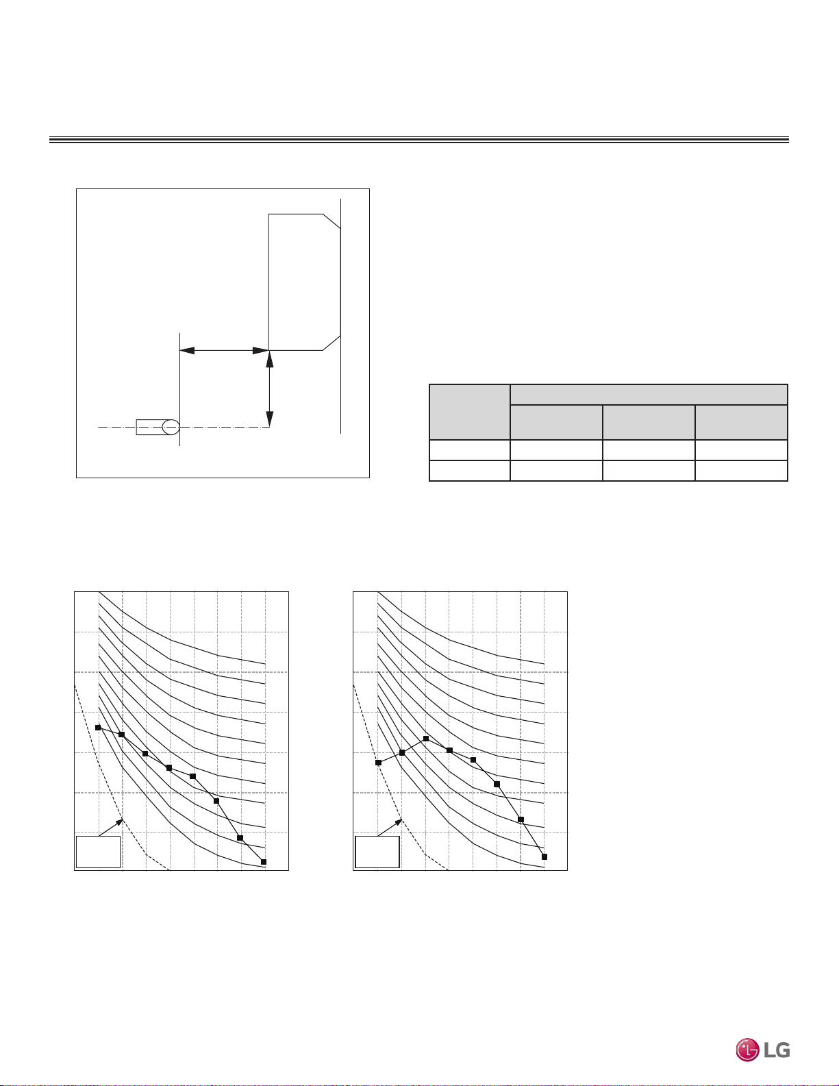
Acoustic Data
• Measurement taken 2.6′ below the bottom of the unit and at a
distance of 3.3′ from face of unit.
• Measurements taken with no attenuation and units operating at full
load normal operating condition.
• Sound level will vary depending on a range of factors such as
construction (acoustic absorption coefficient) of particular area in
which the equipment is installed.
• Sound power levels are measured in dB(A).
• Tested in anechoic chamber per ISO Standard 3745.
Model No.
Sound Pressure Levels (dB[A]) (Cooling and Heating)
High Fan Speed
Medium Fan
Speed
Low Fan Speed
LMAN097HVP 39 35 31
LMAN127HVP 42 38 34
Figure 32: Sound Pressure Level Measurement Location.
Table 16: Sound Pressure Levels (dB[A]).
Figure 33: Sound Pressure Level Diagrams.
ART COOL GALLERY INDOOR UNITS
2.6ft
3.3ft
Microphone
Octave Band Center Frequency (Hz)
Octave Band Sound Pressure Level (0dB = 20μPa)
10
20
30
40
50
60
70
80
63 125 250 500 1000 2000 4000 8000
NC-15
NC-20
NC-25
NC-30
NC-35
NC-40
NC-45
NC-50
NC-55
NC-60
NC-65
Approximate
Hearing
Threshold
Octave Band Center Frequency (Hz)
Octave Band Sound Pressure Level (0dB = 20μPa)
10
20
30
40
50
60
70
80
63 125 250 500 1000 2000 4000 8000
NC-15
NC-20
NC-25
NC-30
NC-35
NC-40
NC-45
NC-50
NC-55
NC-60
NC-65
Approximate
Hearing
Threshold
LMAN097HVP LMAN127HVP
Due to our policy of continuous product innovation, some specications may change without notication.
©LG Electronics U.S.A., Inc., Englewood Cliffs, NJ. All rights reserved. “LG” is a registered trademark of LG Corp.
34 | ART COOL GALLERY™
Multi F and Multi F MAX Indoor Unit Engineering Manual
MULTI
F
MAX
MULTI
F
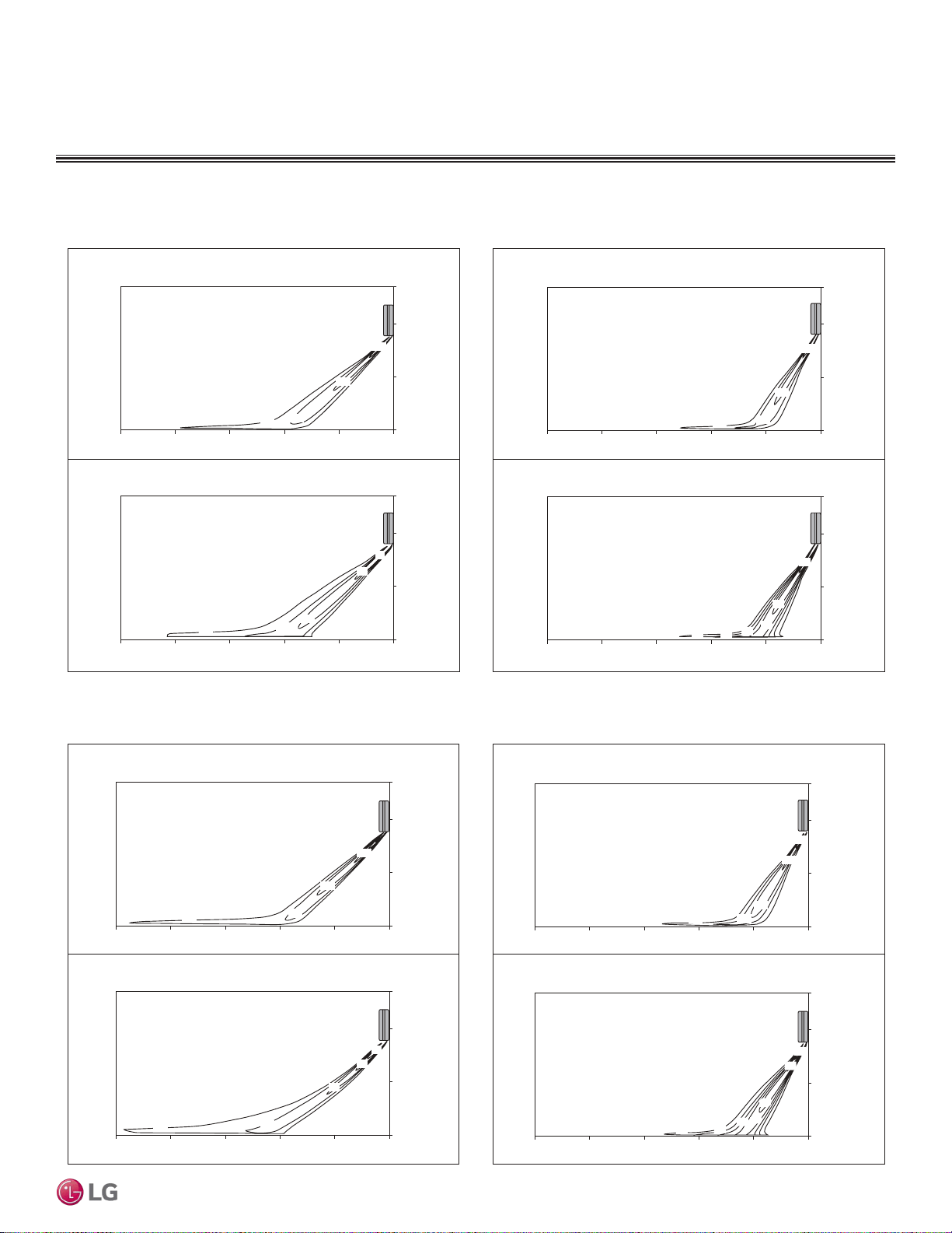
Air Velocity and Temperature Distribution
Figure 34: LMAN097HVP Air Velocity and Temperature Distribution Charts.
Figure 35: LMAN127HVP Air Velocity and Temperature Distribution Charts.
ART COOL GALLERY INDOOR UNITS
Coolin
gH
eating
1.6
3.3
4.6
6.6
63
66
59
52
55
9f t
7f t
3f t
0f t
16ft 13ft 10ft7ft 3f t
0f t
9f t
7f t
3f t
0f t
16ft 13ft 10ft7ft 3f t
0f t
Air velocity [ft/s]
Temperature [°F]
1.6
3.3
4.9
6.6
91
99
95
102
106
109
Air velocity [ft/s]
Temperature [°F]
9f t
7f t
3f t
0f t
16ft 13ft 10ft7ft 3f t
0f t
9f t
7f t
3f t
0f t
16ft 13ft 10ft7ft 3f t
0f t
Discharge angle: 40° Discharge angle: 50°
Cooling Heating
1.6
3.3
4.9
6.6
66
63
59
55
52
Air velocity [ft/s]
Temperature [°F]
9f t
7f t
3f t
0f t
16ft 13ft 10ft 7ft3ft
0f t
9f t
7f t
3f t
0f t
16ft 13ft 10ft 7ft3ft
0f t
95
91
99
102
106
109
11 3
1.6
3.3
4.9
6.6
8.2
Air velocity [ft/s]
Temperature [°F]
9f t
7f t
3f t
0f t
16ft 13ft 10f t7ft 3f t
0f t
9f t
7f t
3f t
0f t
16ft 13ft 10f t7ft 3f t
0f t
Discharge angle : 40°Discharge angle : 50°
ART COOL GALLERY™ | 35
Art Cool Gallery™
Due to our policy of continuous product innovation, some specications may change without notication.
©LG Electronics U.S.A., Inc., Englewood Cliffs, NJ. All rights reserved. “LG” is a registered trademark of LG Corp.
MULTI
F
MAX
MULTI
F
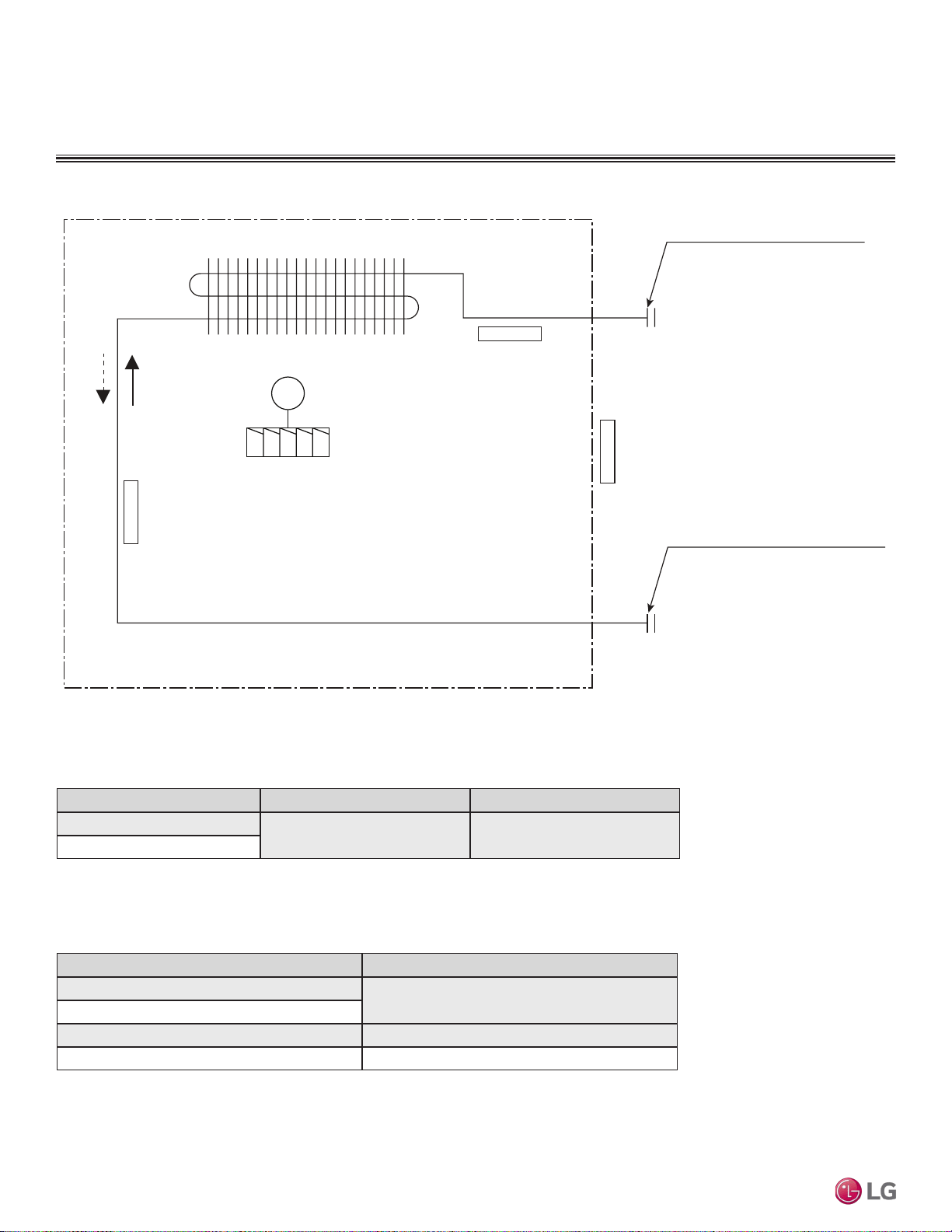
Refrigerant Flow Diagram
Figure 36: Art Cool Gallery Indoor Unit Refrigerant Flow Diagram.
ART COOL GALLERY INDOOR UNITS
Table 17: Art Cool Gallery Indoor Unit Refrigerant Pipe Connection Port Diameters.
Model No. Vapor (inch) Liquid (inch)
LMAN097HVP
Ø3/8 Ø1/4
LMAN127HVP
Table 18: Art Cool Gallery Indoor Unit Thermistor Details.
Description (Based on Cooling Mode) PCB Connector
Indoor Air Temperature Thermistor
CN-TH1
Evaporator Inlet Temperature Thermistor
Evaporator Outlet Temperature Thermistor CN-TH2
Water Level Sensor (Optional) CN-TH3
Gas pipe connection port
(flare connection)
Liquid pipe connection port
(flare connection)
Cooling
Heating
Thermistor for
Evaporator Inlet Temperature
Thermistor for
Indoor Air Temperature
Thermistor for Evaporator
Outlet Temperature
Heat Exchanger
Turbo Fan
M
Due to our policy of continuous product innovation, some specications may change without notication.
©LG Electronics U.S.A., Inc., Englewood Cliffs, NJ. All rights reserved. “LG” is a registered trademark of LG Corp.
36 | ART COOL GALLERY™
Multi F and Multi F MAX Indoor Unit Engineering Manual
MULTI
F
MAX
MULTI
F
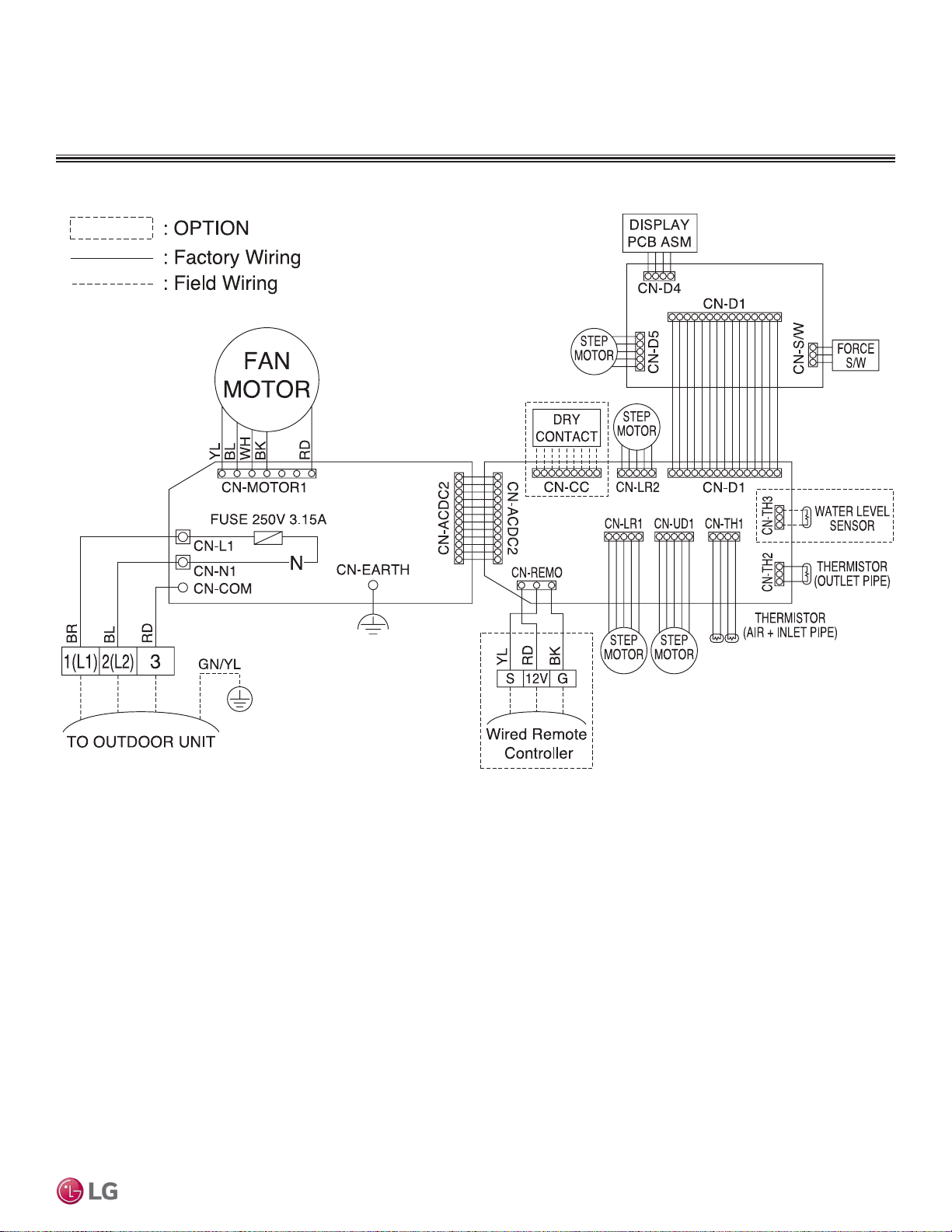
Wiring Diagram
Figure 37: Multi F Art Cool Gallery Indoor Units Wiring Diagram.
ART COOL GALLERY INDOOR UNITS
ART COOL GALLERY™ | 37
Art Cool Gallery™
Due to our policy of continuous product innovation, some specications may change without notication.
©LG Electronics U.S.A., Inc., Englewood Cliffs, NJ. All rights reserved. “LG” is a registered trademark of LG Corp.
MULTI
F
MAX
MULTI
F
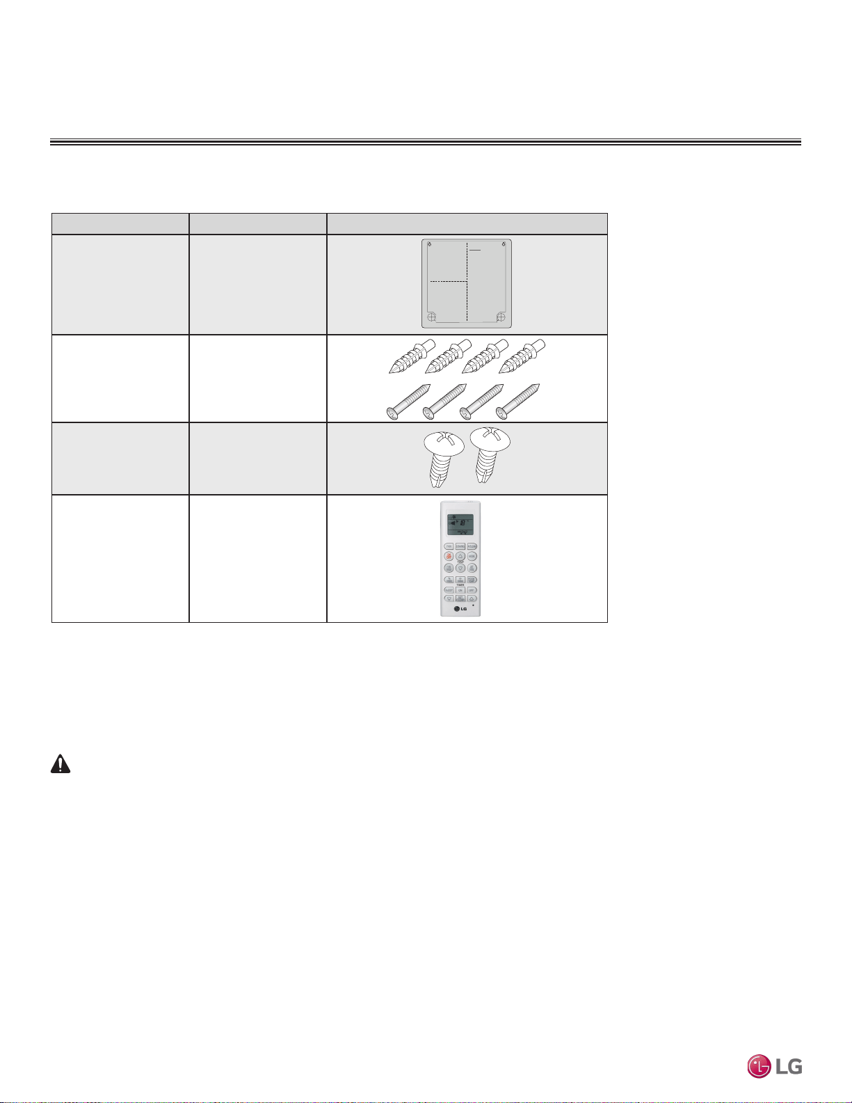
Factory Supplied Parts
Part Quantity Image
Installation Guide One (1)
Type “A” Screws and
Plastic Anchors
Four (4)
Each
Type “B” Screws
(M4 x 12L)
Two (2)
Wireless Handheld
Controller with Holder
(AKB73635607)
One (1)
Factory Supplied Materials
• Owner’s Manual
• Installation Manual
• Level
• Screwdriver
• Electric drill
• Hole core drill
• Flaring tool set
• Spanner (Half union)
• Thermometer
Factory Supplied Parts and Materials
Table 19: Parts Table.
Required Tools
ART COOL GALLERY INDOOR UNITS
WARNING
Installation work must be performed by trained personnel and in accordance with national wiring standards and all local or other applicable codes.
Improper installation can result in re, electric shock, physical injury, or death.
Note:
Read all instructions before installing this product. Become familiar with the unit’s components and connections, and the order of installation. Incorrect
installation can degrade or prevent proper operation.
Due to our policy of continuous product innovation, some specications may change without notication.
©LG Electronics U.S.A., Inc., Englewood Cliffs, NJ. All rights reserved. “LG” is a registered trademark of LG Corp.
38 | ART COOL GALLERY™
Multi F and Multi F MAX Indoor Unit Engineering Manual
MULTI
F
MAX
MULTI
F
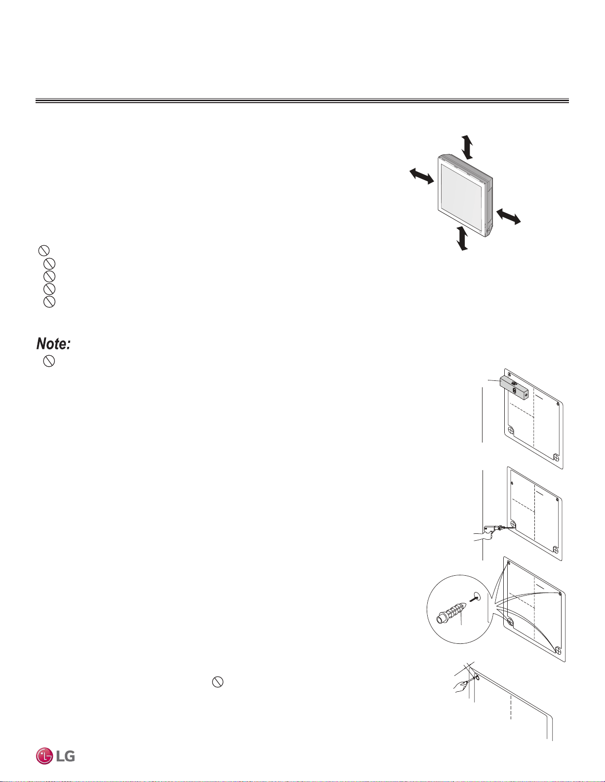
Selecting the Best Location
Do’s
• Place the unit where air circulation will not be blocked.
• Place the unit where drainage can be obtained easily.
• Place the unit where noise prevention is taken into consideration.
• Ensure there is sufficient space from the ceiling and floor.
• Ensure there is sufficient maintenance space.
• Locate the indoor unit in a location where it can be easily connected to the outdoor
unit/branch distribution unit.
Don’ts
• Do not install the unit near a heat or steam source, or where considerable amounts of oil, iron powder, or flour are used.
• Do not install the unit where sulfuric acid and flammable or corrosive gases are generated, vented into, or stored.
• Do not install the unit near high-frequency generators.
• Do not install the unit near a doorway.
The unit will be damaged, will malfunction, and/or will not operate as designed if installed in any of the conditions listed.
Installation and Best Layout Practices
Using the Installation Guide
1. Choose an appropriate location for the indoor unit. To hang the installation guide, verify that it is
level and plumb, and then tape it to the wall.
2. Drill four (4) 1/4-inch diameter holes with a depth of 1-3/16 to 1-3/8 inches for the mounting
screws. Drill one (1) two (2) inch-diameter hole for the field-installed refrigerant and drain piping.
3. Insert a plastic anchor into each of the mounting holes.
4. Screw the top two (2) screws into the wall.
Do not flush them to the wall; leave a 7/16 inch
space for hanging the indoor unit.
Figure 39:Using the Installation Guide.
Note:
If the unit is installed near a body of water, certain components are at risk of being corroded.
Appropriate anti-corrosion methods must be taken for the unit and all components.
ART COOL GALLERY INDOOR UNITS
Figure 38:Minimum Clearance Requirements.
>8 inches
>20 inches
Recommended height
>5 feet from the floor
>20 inches
7/16 inch
Horizontal
Plastic Anchor
1
2
3
4
Installing in an Area Exposed to Unconditioned Air
In some installation applications, areas (oors, walls) in some rooms will be exposed to unconditioned
air (room will be above or next to an unheated garage or storeroom). To countermeasure:
• Verify that carpet is or will be installed (carpet will increase the temperature by three degrees).
• Add insulation between the floor joists.
• Install radiant heat or another type of heating system to the floor.
• Indoor units (IDUs) must not be placed in an environment where the IDUs will be exposed to
harmful volatile organic compounds (VOCs) or in environments where there is improper air make
up or supply or inadequate ventilation. If there are concerns about VOCs in the environment where
the IDUs are installed, proper air make up or supply and/or adequate ventilation must be provided.
Additionally, in buildings where IDUs will be exposed to VOCs, consider a third party factory-applied
epoxy coating to the fan coils for each IDU where the entire coil is dipped, not sprayed.
• If the unit is installed near a body of water, the installation parts are at risk of corroding. Appropriate
anti-corrosion methods must be taken for the unit and all installation parts.
ART COOL GALLERY™ | 39
Art Cool Gallery™
Due to our policy of continuous product innovation, some specications may change without notication.
©LG Electronics U.S.A., Inc., Englewood Cliffs, NJ. All rights reserved. “LG” is a registered trademark of LG Corp.
MULTI
F
MAX
MULTI
F
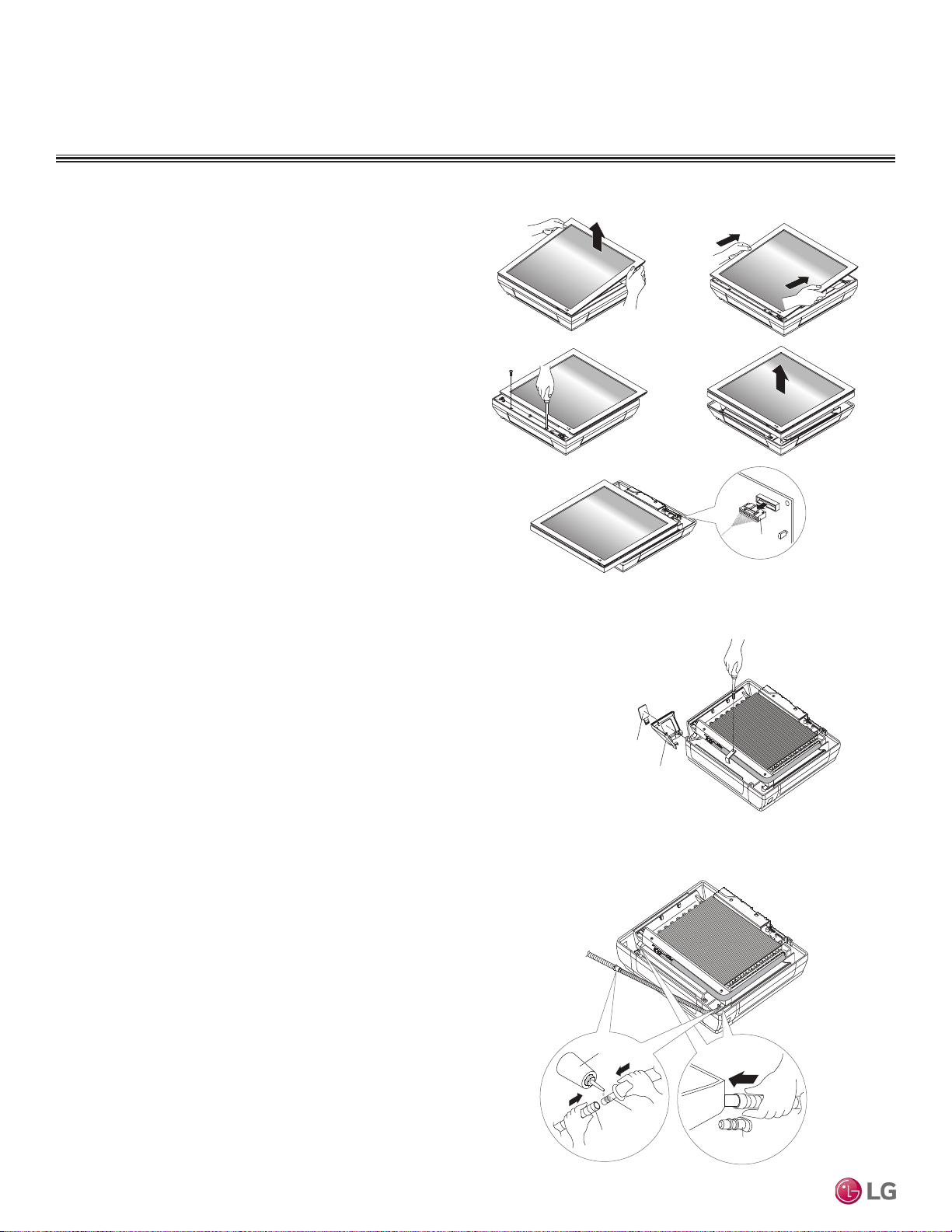
Installation and Best Layout Practices
Preparing the Indoor Unit for
Installation
Removing the Front Panel
1. First pull the top of the front panel up (1A) and then out (1B).
2. Remove the two (2) screws at the bottom (2A), then lift off the front
panel (2B).
3. To completely detach the front panel, disconnect the panel connector
found at the top of the indoor unit (3).
ART COOL GALLERY INDOOR UNITS
Panel Connector
1A 1B
2A 2B
3
Figure 40:Preparing for Installation.
Removing the Piping and Side Covers
1. Unscrew the center cover.
2. Remove the cover from the side of the indoor unit chosen for the piping connections,
and then knock out the piping access hole. If the refrigerant piping will be connected
through the back of the unit, the access hole does not need to be knocked out.
3. Remove any burrs that will have been made.
Side cover
Access Hole
for Piping
Figure 41:Removing the Piping and Side Covers.
Preparing the Drain Hose
1. Remove the rubber stopper from the chosen side of the indoor unit.
2. Insert the drain hose into the handle of the drain pan.
3. Connect the drain hose to the field-installed drain piping.
Rubber Stopper
Choose a Side
for the Drain
Connections
Field-Installed
Drain Piping
Adhesive
Drain
Hose
Figure 42:Preparing the Drain Hose.
Due to our policy of continuous product innovation, some specications may change without notication.
©LG Electronics U.S.A., Inc., Englewood Cliffs, NJ. All rights reserved. “LG” is a registered trademark of LG Corp.
40 | ART COOL GALLERY™
Multi F and Multi F MAX Indoor Unit Engineering Manual
MULTI
F
MAX
MULTI
F
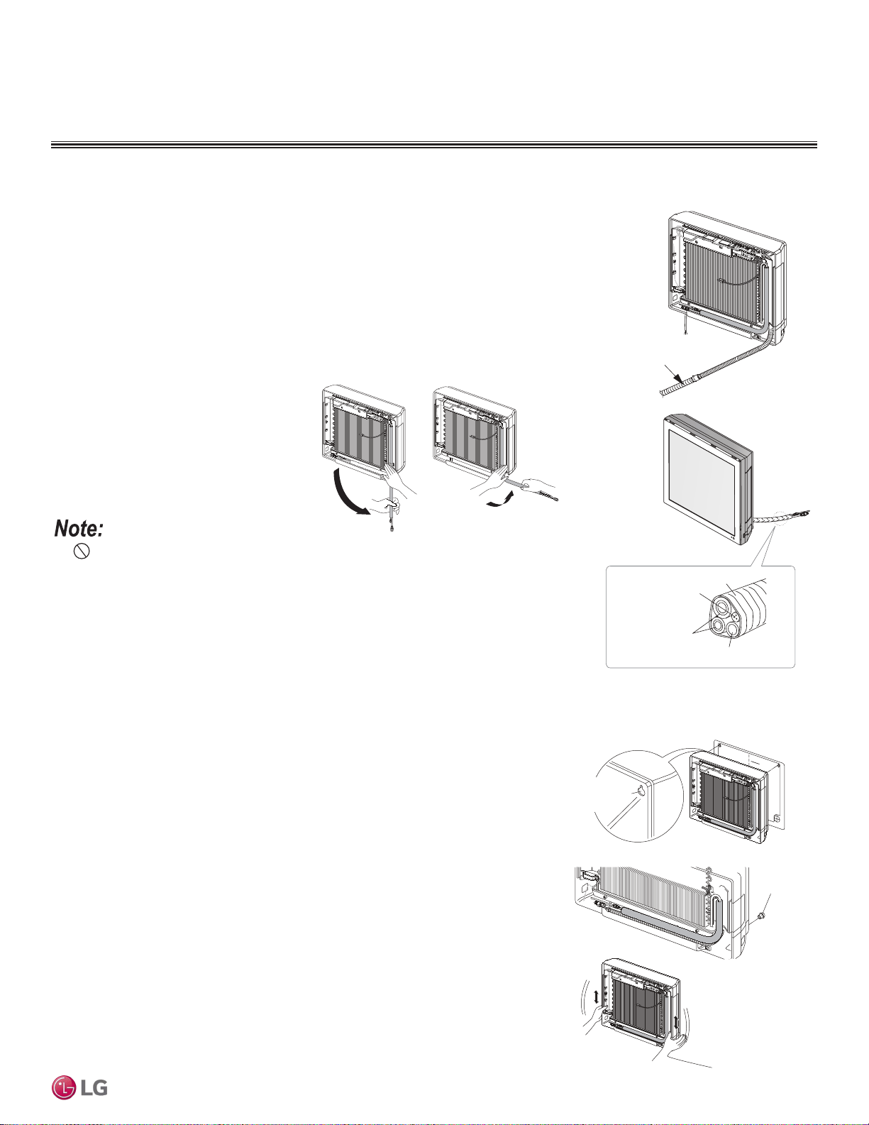
Hanging the Indoor Unit Frame
1. Remove the installation guide and hang the indoor unit on the top two (2) screws. Verify
the indoor unit is hanging securely on the screws.
2. Align the holes at the bottom of the indoor unit to the mounting holes. Tighten first the top
screws, then tighten the bottom screws.
3. Verify that the indoor unit is completely secured to the wall by gently shaking it up and
down.
ART COOL GALLERY INDOOR UNITS
Installation and Best Layout Practices
Plastic Anchors
Installation Guid
e
Holes for Hanging
(On back of
indoor unit)
1
2
3
Preparing the Refrigerant and Drain Piping Connections
1. Depending on the installation requirements, route the indoor unit refrigerant piping and the
drain hose to the left, right (see guidelines below), or rear of the frame.
2. Bundle the piping and drain hose with tape where they meet near the indoor unit frame. Po-
sition the drain hose at the bottom of the bundle (positioning the drain hose at the top of the
bundle will cause the drain pan to overflow inside the indoor unit).
Drain hose
Loop
Connecting
pipe
Power wiring /
Communication
cable
Tape
Drain hose
1
2
Figure 43:Preparing the Refrigerant /
Drain Connections.
1. Press on the top of the clamp, and then
slowly guide the piping downward.
2. Bend the piping to the right side of the
indoor unit frame.
Do not bend the piping/drain hose from side to side; it will damage the components.
12
Figure 44:Right Side Piping Access.
Installing Piping on the Right Side of the Indoor Unit Frame
Figure 45:Hanging the Indoor Unit Frame.
ART COOL GALLERY™ | 41
Art Cool Gallery™
Due to our policy of continuous product innovation, some specications may change without notication.
©LG Electronics U.S.A., Inc., Englewood Cliffs, NJ. All rights reserved. “LG” is a registered trademark of LG Corp.
MULTI
F
MAX
MULTI
F
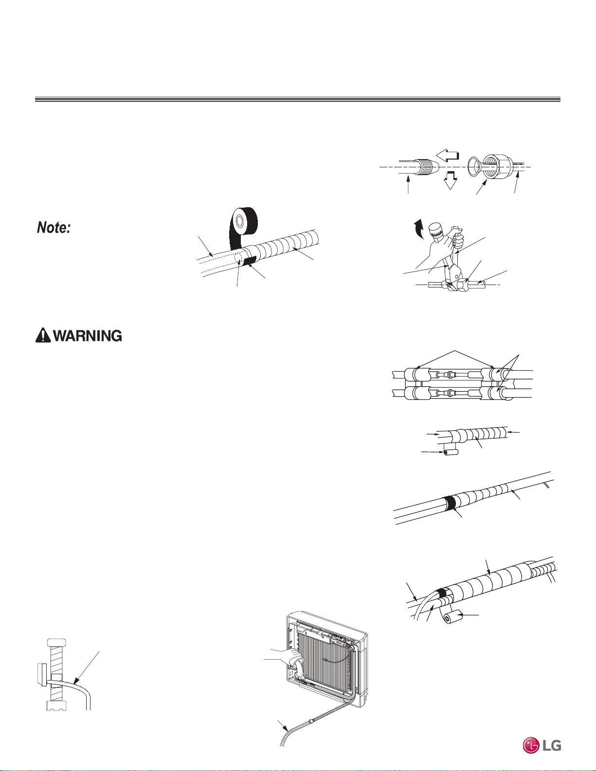
ART COOL GALLERY INDOOR UNITS
Connecting the Indoor Unit Piping to the Field-Installed Piping
If the drain hose is routed in-
side a room, add insulation
to prevent condensation from
forming.
1. Center align the indoor unit piping (refrigerant and drain) and the field-installed
piping, then hand tighten the flare nut.
2. Tighten the flare nut with a torque wrench.
3. Attach the drain tube piping to the indoor unit drain hose as shown below.
Indoor unit piping
Flare nut Field-installed
piping
Spanner
Field-installed
piping
Flare nut
Torque
wrench
Figure 46:Indoor Unit to Field-Installed Piping Connection.
Narrow tape
Adhesive
Drain extension
Indoor unit
drain hose
Figure 47:Extending the Drain Hose.
Bands
Insulation
Narrow tape
Field-supplied
piping
Wide tape
Wrap with tape
Indoor unit
piping
Piping
Wrap with tape
Drain hose
Piping
Wide tape
1.
2.
3.
Figure 48:Insulating the Piping.
Installation and Best Layout Practices
Drain Slope
Drain hose must point
down so water can flow
away easily.
Slope Down
Figure 49:Drain Piping Slope.
Checking the Drainage System
Figure 50:Checking the Drainage
System.
1. Pour water on the in-
door unit evaporator.
2. Ensure the water
flows through and out
of the hose and away
from the indoor unit
without leaking.
Indoor Unit s
Drain extension
Refrigerant Piping Insulation
Field-installed vapor and liquid refrigerant piping lines must be properly and completely
covered in insulation (up to the indoor unit piping connections). Any exposed piping will
generate condensate or will cause burns if touched. Insulation for this field-installed refrig-
erant piping must have a minimum heat resistance of 248°F.
Drain Piping Insulation
Drain piping must have insulation a minimum of 7/32 inches thick.
Installing the Insulation
1. Overlap the insulation at the connection of the field-installed piping and the indoor unit
piping. Tape together so there are no gaps.
2. Secure insulation to the rear piping housing section with vinyl tape.
3. Bundle the piping and drain hose with tape where they meet at the back of the indoor
unit frame. Position the drain hose at the bottom of the bundle (positioning the drain
hose at the top of the bundle will cause the drain pan to overflow inside the indoor
unit).
Insulating the Refrigerant and Drain Piping
Ensure all piping is insulated. Exposed piping can cause burns if touched.
Due to our policy of continuous product innovation, some specications may change without notication.
©LG Electronics U.S.A., Inc., Englewood Cliffs, NJ. All rights reserved. “LG” is a registered trademark of LG Corp.
42 | ART COOL GALLERY™
Multi F and Multi F MAX Indoor Unit Engineering Manual
MULTI
F
MAX
MULTI
F
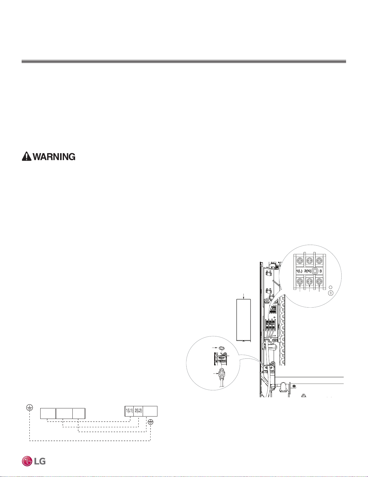
Power Wiring / Communications Cable Guidelines
ART COOL GALLERY INDOOR UNITS
Connecting the Power Wiring and Communications Cable
Installation and Best Layout Practices
Control Board Cover
Lock nut
(field supplied)
Conduit
(field supplied)
1(L1)2(L2) 3
Figure 51:Connecting the Power Wiring / Communications Cable.
1. Insert the power wiring/communications cable from the out-
door unit or branch distribution unit (Multi F MAX systems only)
through the access hole of the indoor unit (ground wire must be
longer than the other wires/cables). Unscrew the control board
cover.
2. Connect each wire to its appropriate terminal on the indoor unit
control board. Verify that the color and terminal numbers from
the outdoor unit or branch distribution unit (Multi F MAX systems
only) wiring match the color and terminal numbers on the indoor
unit.
3. Secure the power wiring/communications cable to the control
board.
4. Reattach the control board cover.
Figure 52:Simplied View of Indoor Unit to Outdoor Unit / Branch
Distribution Unit Terminal Connections—LMAN097HVP and
LMAN127HVP models.
• Follow manufacturer’s circuit diagrams in the technical manuals.
• Confirm power source specifications.
• Confirm that the electrical capacity is sufficient.
• Starting current must be maintained ±10 percent of the rated current marked on the outdoor unit name plate.
• Confirm cable thickness specifications.
• It is required that a circuit breaker is installed, especially if conditions could become wet or moist.
• Include a disconnect in the power wiring system, add an air gap contact separation of at least 1/8 inch in each active (phase) conductor.
Indoor Unit Terminal Block
GND
Outdoor Unit Terminal Block or
Branch Distribution Unit Terminal Block
(Multi F MAX Systems Only)
GND
GRN / YLW
BR
BL
RD
3 or S
32(L2)1(L1)
• Loose wiring will cause unit to malfunction, overheat, and catch fire, resulting in severe injury or death.
Note:
• Terminal screws will become loose during transport. Properly tighten the terminal connections during installation.
A voltage drop will cause the following problems:
• Magnetic switch vibration, fuse breaks, or disturbance to the normal function of an overload protection device.
• Compressor will not receive the proper starting current.
ART COOL GALLERY™ | 43
Art Cool Gallery™
Due to our policy of continuous product innovation, some specications may change without notication.
©LG Electronics U.S.A., Inc., Englewood Cliffs, NJ. All rights reserved. “LG” is a registered trademark of LG Corp.
MULTI
F
MAX
MULTI
F
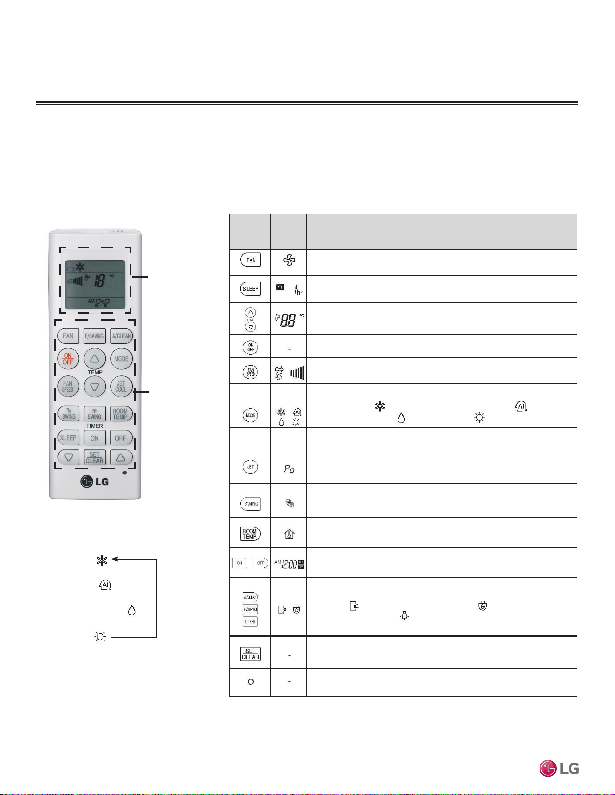
ART COOL GALLERY INDOOR UNITS
Installation and Best Layout Practices
Controller Options
Art Cool Gallery wall-mounted indoor units include a handheld controller (AKB73635607), but optional LG-supplied wired controllers are
available.
Display
Screen
Figure 53:AKB73635607
Wireless Controller.
1
Depending on the indoor unit model, some functions will not be supported.
Control
Panel
Table 20: AKB73635607 Wireless Controller Functions.
Control
Panel
Button
Display
Screen
Description
Air circulation button
1
: Circulates the room air without operating in cooling
or heating mode.
Sleep Mode Auto Button
1
: Sets the sleep mode auto operation.
Temperature Adjustment Buttons: Raises or lowers temperature setpoint in
cooling and heating operation.
On / Off Button: Turns the power on/off.
Indoor Fan Speed Button: Changes the fan speed.
Operation mode selection button
1
: Selects the operation mode.
Cooling operation / Auto operation or auto changeover /
Dehumidifying operation / Heating operation
Jet Cool / Jet Heat Button
1
: Warms up or cools down the indoor
temperature within a short period.
Air Flow Direction Button: Adjusts the airflow direction.
Temperature Display Button: Displays the room temperature. Press and
hold button down for five (5) seconds to change from °C to °F.
Timer button: Sets the current time and the start/end times.
Navigation/Functions Button
1
: Adjusts the time and sets the special functions.
Auto clean / Operates energy saving cooling / Adjusts the brightness
of the indoor unit display
Set/Clear Button: Sets or cancels functions.
Reset Button: Resets the air conditioner settings.
Wireless Handheld Controller
Operation Mode Sequence
Cooling Mode
↓
Auto Operation
↓
Dehumidification Mode
↓
Heating Mode
Due to our policy of continuous product innovation, some specications may change without notication.
©LG Electronics U.S.A., Inc., Englewood Cliffs, NJ. All rights reserved. “LG” is a registered trademark of LG Corp.
44 | ART COOL GALLERY™
Multi F and Multi F MAX Indoor Unit Engineering Manual
MULTI
F
MAX
MULTI
F
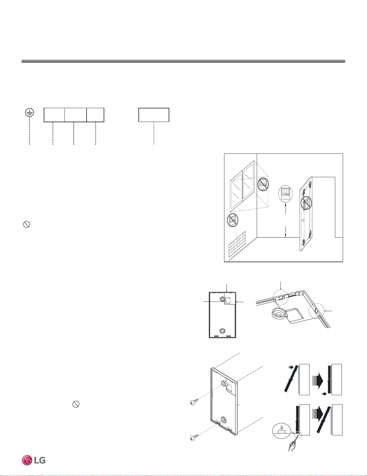
ART COOL GALLERY INDOOR UNITS
Installation and Best Layout Practices
Figure 54:Wired Controller Connection on the Indoor Unit Terminal Block.
Wired Controller Connections
Figure 55:Proper Location for the Wired Controller.
Wired controllers include a sensor to detect room temperature. To maintain comfort
levels in the conditioned space, the wired controller must be installed in a location
away from direct sunlight, high humidity, and where it could be directly exposed to
cold air. Controller must be installed four (4) to five (5) feet above the floor where its
LED display can be read easily, in an area with good air circulation, and where it can
detect an average room temperature.
Do not install the wired controller near or in:
• Drafts or dead spots behind doors and in corners
• Hot or cold air from ducts
• Radiant heat from the sun or appliances
• Concealed pipes and chimneys
• An area where temperatures are uncontrolled, such as an outside wall
Wired Controller Placement
4 to 5 feet
above the floor
NO
NO
NO
YES
Remote Controller
TEMP
Remote Controller
TEMP
Re
m
ot
e Co
nt
roller
TEMP
Hanging the Wired Controller
1. The controller wiring/cable can be installed in one of three direc-
tions: top, back, or on the right side. If top or right side installation
is desired, remove cable guide grooves on the controller, and
then position wiring/cable on applicable side.
2. Choose and mark the area of installation, and then screw the wall
plate into place (using the provided parts). Install the controller
wall plate to fit the electrical box if one is present. Ensure that no
gaps exist between the wall plate and the wall itself.
3. Arrange wiring/cables so as not to interfere with the controller
circuitry. Position the wired controller on the wall plate. Snap into
place by pressing the bottom part of the wired controller onto
the wall plate. Make sure that no gaps exist between the wired
controller and the wall plate on all sides.
4. To remove wired controller from the wall plate, insert a screw-
driver into the two holes at the bottom. Twist screwdriver to
release controller. Do not damage the controller components
when removing.
Back
Top
Top
Right
Side
Right
Side
Wall Wall
Wall Wall
Installing the Controller
Removing the Controller
Figure 56:Removing the Cable Guide Grooves.
Figure 57:Attaching the Wall Plate.
Figure 58:Installing/Removing the
Controller.
Indoor Unit Terminal Block
1(L1 )2(L2)
GND
GRN / YLW
BR
BL
RD
CN-REMO
To Outdoor Unit or Branch Distribution Unit
(Multi F MAX Systems Only)
To Wired Controller
3
ART COOL GALLERY™ | 45
Art Cool Gallery™
Due to our policy of continuous product innovation, some specications may change without notication.
©LG Electronics U.S.A., Inc., Englewood Cliffs, NJ. All rights reserved. “LG” is a registered trademark of LG Corp.
MULTI
F
MAX
MULTI
F
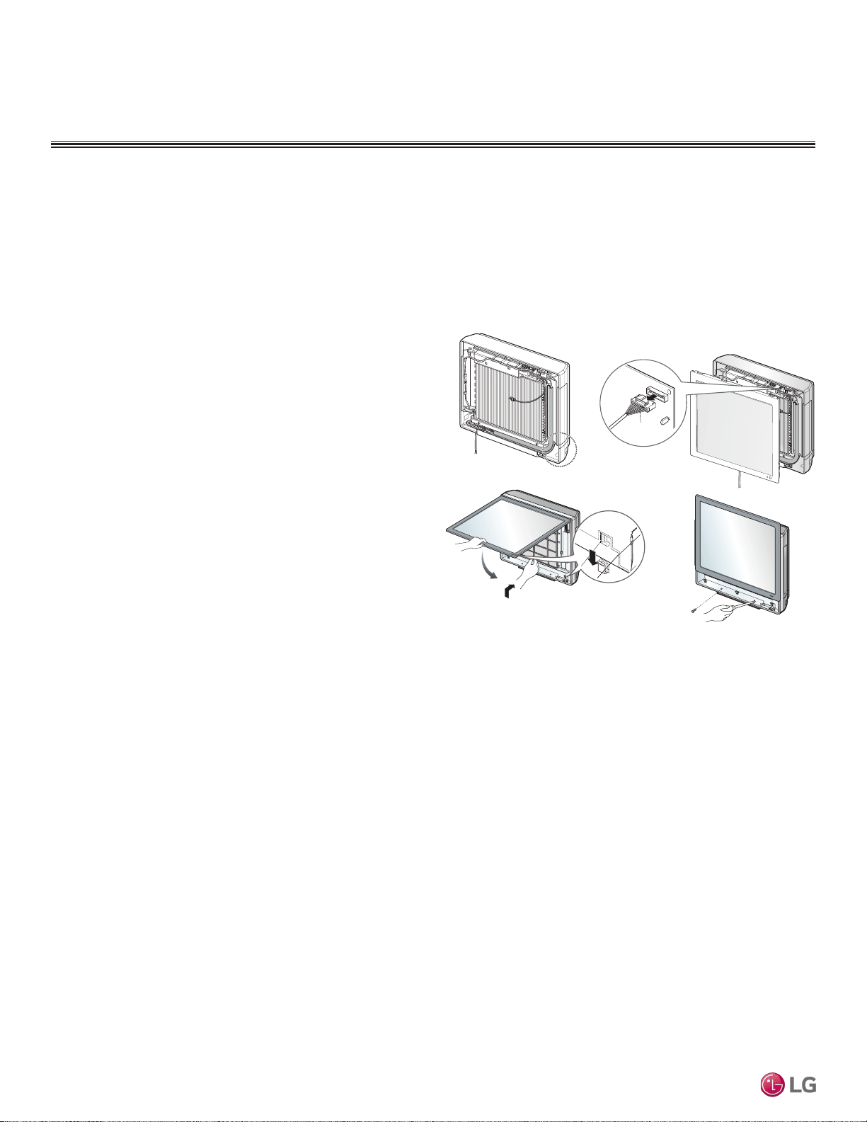
Assigning the Thermistor for Temperature Detection
Each indoor unit includes a return air thermistor assigned to sense the temperature. If a wired controller is installed, there is a choice of
sensing temperature with either the indoor unit return air thermistor or the thermistor in the wired controller. It is also an option to set both
thermistors to sense temperature so that indoor unit bases its operation on the first thermistor to reach the designated temperature differen-
tial. For applicable indoor units, an optional Remote Temperature Sensor can be used in lieu of the return air thermistor—either alone or in
conjunction with a wired controller thermistor as previously described.
Finalizing Indoor Unit Installation
1. Verify that the side covers are closed or opened, depending on
installation requirements. Place the power wiring / communica-
tions cable in the bottom groove along the left side of the frame.
2. Reconnect the panel connector found at the top of the indoor unit.
3. Attach the top part of the front panel, then position its tabs in the
grooves on the bottom part of the indoor unit frame.
4. To ensure the front panel tabs are securely positioned in the
grooves, adjust the panel by loosening or tightening the screws
at the bottom.
Figure 59:Final Installation Step—Reattaching the Front Panel.
Front Panel
Connector
12
34
ART COOL GALLERY INDOOR UNITS
Installation and Best Layout Practices
Due to our policy of continuous product innovation, some specications may change without notication.
©LG Electronics U.S.A., Inc., Englewood Cliffs, NJ. All rights reserved. “LG” is a registered trademark of LG Corp.
46 | ART COOL GALLERY™
Multi F and Multi F MAX Indoor Unit Engineering Manual
MULTI
F
MAX
MULTI
F
ART COOL GALLERY™ | 47
Art Cool Gallery™
Due to our policy of continuous product innovation, some specications may change without notication.
©LG Electronics U.S.A., Inc., Englewood Cliffs, NJ. All rights reserved. “LG” is a registered trademark of LG Corp.
MULTI
F
MAX
MULTI
F

“Mechanical Specifications” on page 49
“General Data / Specifications” on page 50
“Dimensions” on page 51
“Cooling Capacity Table” on page 53
“Heating Capacity Table” on page 56
“Acoustic Data” on page 58
“Air Velocity and Temperature Distribution” on page 60
“Refrigerant Flow Diagram” on page 62
“Wiring Diagram” on page 63
“Factory Supplied Parts and Materials” on page 65
“Installation and Best Layout Practices” on page 66
STANDARD
WALL-MOUNTED
INDOOR UNIT DATA
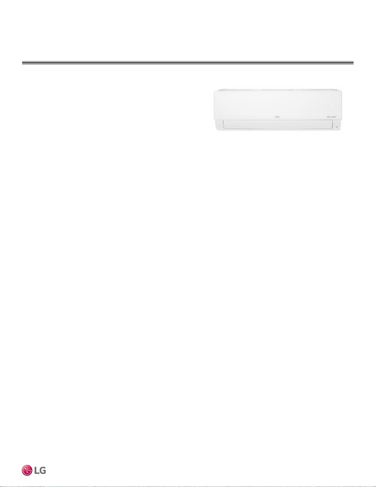
STD. WALL-MOUNTED | 49
Standard Wall-Mounted
Due to our policy of continuous product innovation, some specications may change without notication.
©LG Electronics U.S.A., Inc., Englewood Cliffs, NJ. All rights reserved. “LG” is a registered trademark of LG Corp.
MULTI
F
MAX
MULTI
F
STANDARD WALL-MOUNTED INDOOR UNITS
Mechanical Specications and Features
Standard Wall-Mounted Indoor Units
General
All LG indoor units are factory assembled, wired, piped, and pro-
vided with a control circuit board, fan, and motor. Standard Wall-
Mounted units have a sound rating no higher than 46 dB(A) as tested
per KSA0701 ISO Standard 3745.
Coil
Indoor unit coils are comprised of a minimum of two rows of
aluminum fins mechanically bonded to copper tubing. The coils are
pressure tested at the factory. Each unit is provided with a factory
installed condensate drain pan below the coil.
Refrigerant System
The system is designed for use with R410A refrigerant. The refrig-
eration circuit is pressure-tested at the factory and shipped with a
holding charge of helium gas. Refrigerant pipe connections are 45°
flare. All refrigerant lines from the outdoor unit to the indoor units
must be field insulated.
Electrical
The indoor units require 208–230Vac/60Hz/1Φ power with voltage
variance of no more than ±10%.
Casing
The units mount on a vertical surface. They are shipped with a sepa-
rate back plate that secures the unit to the wall, protruding no more
than nine (9) inches. Refrigerant piping can be installed in one (1) of
four (4) different directions.
Finish
The Standard Wall-Mounted unit has a curved architectural panel
with a pearl white finish. Unit casing has a pearl white or dark gray
finish and is manufactured of heavy-duty acrylonitrile butadiene
styrene (ABS) and high impact polystyrene (HIPS) plastic.
Fan Assembly and Control
The unit has a single, direct-drive, crossow fan made of high strength
ABS plastic. The fan motor is brushless digitally controlled (BLDC)
with permanently lubricated and sealed ball bearings. The fan / motor
assembly is mounted on vibration attenuating rubber grommets. Fan
speed is controlled using a microprocessor-based direct digitally
controlled algorithm that provides pre-programmed, eld-selectable
xed or auto fan speeds in the Heating and Cooling modes. For
Standard Wall-Mounted units, the indoor fan has Low, Med, High, Jet
Cool, and Auto settings for Cooling mode; and has Low, Med, High,
Jet Heat, and Auto settings for Heating mode. The Auto setting adjusts
the fan speed based on the difference between the controller setpoint
and space temperature. Also, the separate Chaos setting provides a
simultaneous and random change in fan speed and ow direction at
the discharge, simulating a natural outdoor breeze.
Air Filter
The return air inlet has a factory-supplied primary removable, wash-
able filter. The unit is also equipped with a secondary 3M Micro Dust
filter. Filters are accessed from the front of the unit without the use
of tools.
Airflow Guide Vanes
A factory-installed motorized guide vane controls the direction of
airflow from side to side. A motorized louver provides an automatic
change in airflow by directing the air up and down for uniform air
distribution.
Microprocessor Control
The indoor unit has an integrated control panel to communicate with
the outdoor unit. All unit operation parameters are stored in non-vola-
tile memory resident on the unit microprocessor. The microprocessor
controls space temperature through using the value provided by the
temperature sensor within the indoor unit. The microprocessor control
will activate indoor unit operation when the indoor room temperature
falls below or rises above a setpoint temperature, at which point, a
signal is sent to the outdoor unit to begin the appropriate mode. The
microprocessor also provides self-diagnostics and auto restart func-
tions. A eld-supplied four-wire power / communications cable must
be installed to connect the indoor unit(s) to the outdoor unit.
Controls
The indoor unit casing has a factory-standard, integral infrared sen-
sor to communicate with the supplied LG wireless handheld remote
controller. An optional LG supplied wired controller is available as
an additional accessory. Communication between the indoor units
and the outdoor unit is accomplished through 14 AWG, four-core,
stranded and shielded power / communication cable. The indoor unit
has built-in wi-fi and can be controlled with LG’s SmartThinQ app on
a smart device. A field-supplied wi-fi network and smart device are
required. The SmartThinQ app is free and is available for Android
and iOS smart devices.
Condensate
The unit is designed for gravity draining of condensate and includes
a flexible drain hose capable of installation in one of two directions.
The unit also includes a connection that is compatible with the Aqua-
Guard
®
AG-9300-LG condensate sensor.
• Inverter (Variable speed fan)
• Comfort Air
• 3M filter
• Jet cool/Jet Heat
• Group control
• Self-cleaning indoor coil
• Auto operation
• Auto restart operation
• Built-in wi-fi
• Dehumidifying function
• Self-diagnostic function
• Wireless LCD remote control included
Features
Figure 60: Multi F Standard Wall-Mounted Indoor Unit.
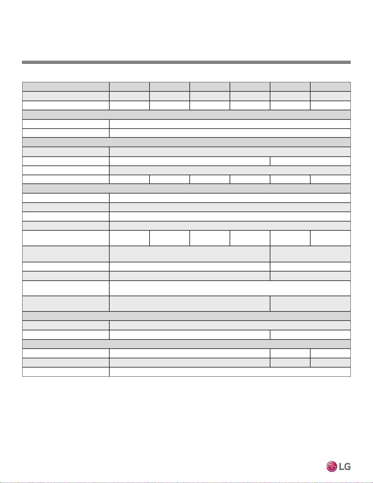
Due to our policy of continuous product innovation, some specications may change without notication.
©LG Electronics U.S.A., Inc., Englewood Cliffs, NJ. All rights reserved. “LG” is a registered trademark of LG Corp.
50 | STD. WALL-MOUNTED
Multi F and Multi F MAX Indoor Unit Engineering Manual
MULTI
F
MAX
MULTI
F
General Data / Specications
Model Name LMN079HVT LSN090HSV5 LSN120HSV5 LMN159HVT LSN180HSV5 LMN249HVT
Nominal Cooling Capacity (Btu/h)
1
7,000 9,000 12,000 14,300 18,000 24,000
Nominal Heating Capacity (Btu/h)
1
8,100 10,900 13,600 15,600 21,600 25,600
Operating Range
Cooling (°F WB)
57-77
Heating (°F DB)
59-81
Fan
Type
Cross Flow
Motor Output (W) x Qty.
30 x 1 60 x 1
Motor/Drive
Brushless Digitally Controlled / Direct
Airflow Rate CFM (H/M/L)
254 / 204 / 148 268 / 218 / 169 282 / 233 / 177 314 / 268 / 184 558 / 438 / 353 597 / 452 / 367
Unit Data
Refrigerant Type
2
R410A
Refrigerant Control
EEV
Power Supply V, Ø, Hz
3
208-230, 1, 60
Rated Amps (A)
0.4
Sound Pressure Level dB(A)
(H/M/L)
4
35 / 31 / 26 36 / 32 / 27 38 / 34 / 29 42 / 38 / 32 44 / 38 / 34 46 / 41 / 36
Dimensions (W x H x D, in.)
32-15/16 x
12-1/8 x 7-7/16
39-9/32 x
13-19/32 x 8-9/32
Net Unit Weight (lbs.)
18.3 25.6
Shipping Weight (lbs.)
23.4 32.2
Power Wiring / Communications
Cable (No. x AWG)
5
4 x 14
Heat Exchanger (Row x Column x
Fin / inch) x Number
(2 x 23 x 22) x 1 (2 x 16 x 20) x 1
Pipe Size
Liquid (in.)
1/4
Vapor (in.)
3/8 1/2
Connection Size
Liquid (in.)
1/4 3/8 1/4
Vapor (in.)
3/8 5/8 1/2
Drain O.D. / I.D. (in.)
27/32, 5/8
Table 21: Multi F Standard Wall-Mounted Indoor Unit General Data.
STANDARD WALL-MOUNTED INDOOR UNITS
1
Nominal capacity is rated 0 ft. above sea level with corresponding refrigerant piping length in
accordance with standard length of each outdoor unit and a 0 ft. level difference between outdoor and
indoor units. All capacities are net with a combination ratio between 95 – 105%.
Nominal cooling capacity rating obtained with air entering the indoor unit at 80ºF dry bulb (DB) and 67ºF
wet bulb (WB) and outdoor ambient conditions of 95ºF dry bulb (DB) and 75ºF wet bulb (WB).
Nominal heating capacity rating obtained with air entering the indoor unit at 70ºF dry bulb (DB) and 60ºF
wet bulb (WB) and outdoor ambient conditions of 47ºF dry bulb (DB) and 43ºF wet bulb (WB).
2
This unit comes with a dry helium charge.
3
Acceptable operating voltage: 187V-253V.
4
Sound pressure levels are tested in an anechoic chamber under ISO Standard 3745 and are the
same in both cooling and heating mode. These values can increase due to ambient conditions during
operation.
5
All power wiring / communications cable to the IDUs be minimum 14 AWG, 4-conductor, stranded,
shielded or unshielded (if shielded, must be grounded to chassis at ODU only) and must comply with
applicable local and national codes.
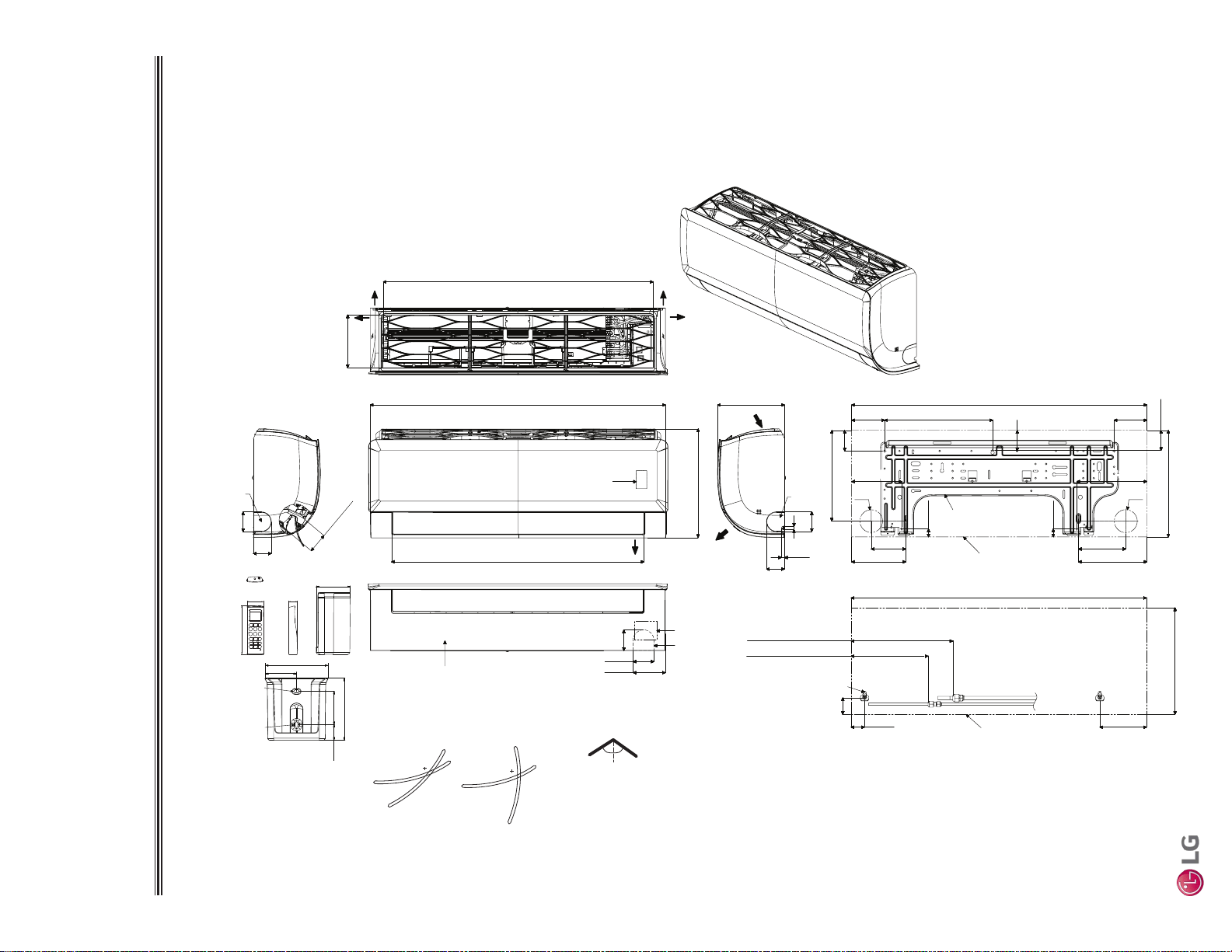
STD. WALL-MOUNTED | 51
Standard Wall-Mounted
Due to our policy of continuous product innovation, some specications may change without notication.
©LG Electronics U.S.A., Inc., Englewood Cliffs, NJ. All rights reserved. “LG” is a registered trademark of LG Corp.
MULTI
F
MAX
MULTI
F
Dimensions
STANDARD WALL-MOUNTED INDOOR UNITS
Figure 61: LMN079HVT, LSN090HSV5, LSN120HSV5, and LMN159HVT Dimensions.
Unit : Inch (mm)
30-3/16 (767)
32-15/16 (837)
3-5/8 (92)
2-3/8 (60)
2-5/16
(59)
12-1/8 (308)
7-7/16 (189)
32-15/16 (837)
1-1/2 (38)
Approx. 8-19/32 (218) to liquid pipe
Approx. 11-11/32 (288) to gas pipe
1-27/32(47)
5-3/16 (132)
In Case of Left Side Piping
Unit Outline
Connecting Gas/Liquid Pipe
12-1/8 (308)
2-7/32(56)
11/32 (9)
5/16 (8)
2 (51)
Air Intake
Air Outlet
Bottom
[28-5/32 (715)]
Air Outlet Hole
* If airflow direction control is available,
Cooling Heating
Up & Down Left & Right
Air Outlet Hole
Air Intake Hole
[5-29/32 (150)]
Air Intake Hole
Rear
Rear
Right
Left
55°
15°
15°
85°
45°
55°
32-15/16 (837)
2-15/32
(63)
12-1/16 (306)
3-21/32 (93)
10-11/32 (263)
5-31/32 (152)
3-27/32 (98)
5-9/32 (134)
12-1/8 (308)
3-11/16 (94)
7-5/8 (194)
Unit Outline
Fixing the Installation Plate, Drilling Hole
29/32 (23)
Ø2-9/16 (65)
2-7/16 ( 61.5)
1-7/16 (33.5)
1-9/32 (32.7)
2-13/32
(61)
5-31/32 (152)
2-7/32 (56)
2 (51)
2-7/32 (56)
Ø2-9/16 (65)
29/32 (23)
2-15/32 (63)
2-17/32 (64)
5-19/32 (142)
7-27/32 (199)
7-27/32 (199)
1/4 (6) x 1/8 (3)
1/8 (3) x 1/4 (6)
5/8 (15.3)
1-1/4 (31)
1-3/32 (50.2)
1-1/16 (26.2)
Refrigerant,
Drain Pipe
and Cable
Routing
Knock Out
Hole
Refrigerant,
Drain Pipe
and Cable
Routing
Knock Out
Hole
Terminal Block for
Power Supply and
Communication
Refrigerant, Drain
Pipe and Cable
Routing Knock Out Hole
Drain Hose
Connection
Display & Remote
Controller Signal
Receiver
Decoration Cover
Installation Plate
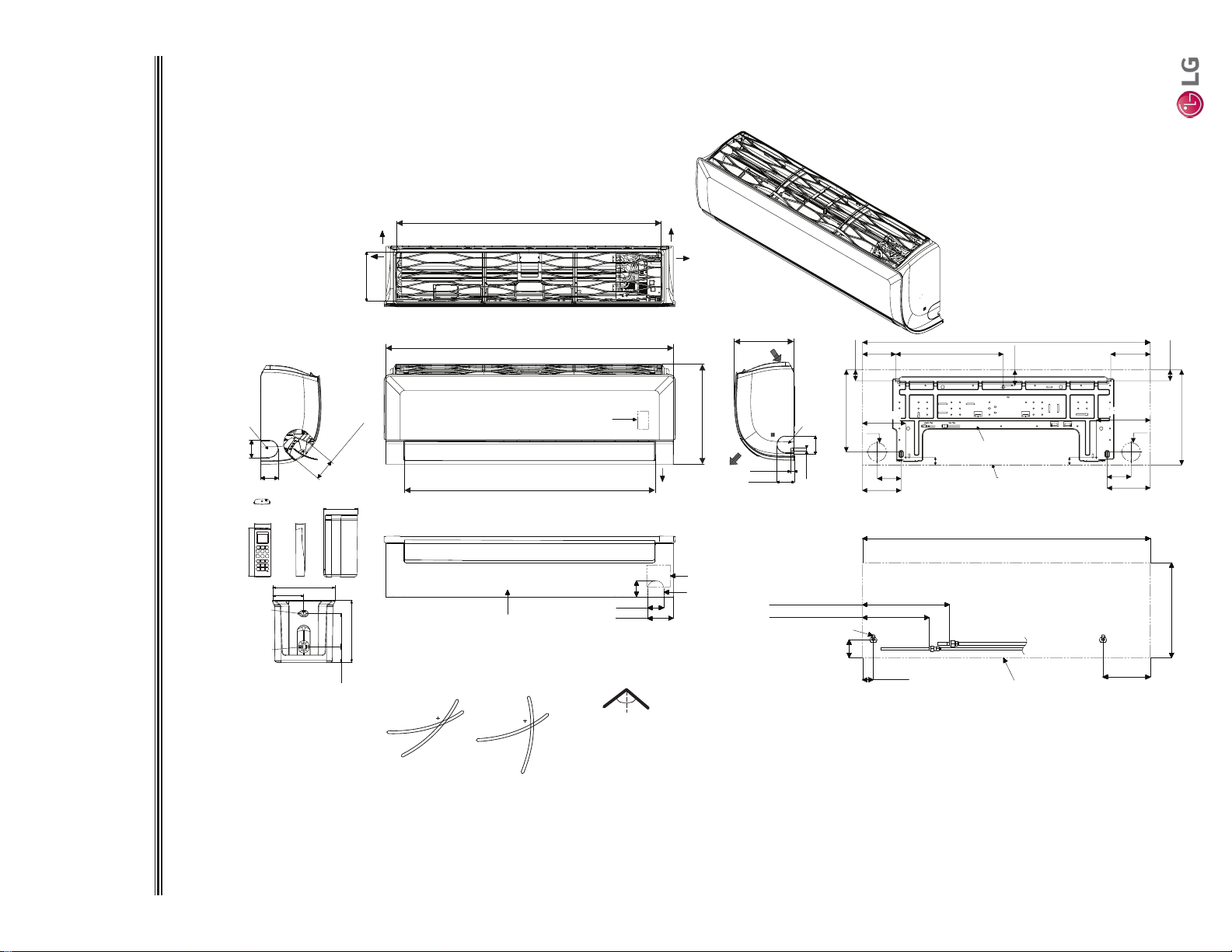
Due to our policy of continuous product innovation, some specications may change without notication.
©LG Electronics U.S.A., Inc., Englewood Cliffs, NJ. All rights reserved. “LG” is a registered trademark of LG Corp.
52 | STD. WALL-MOUNTED
Multi F and Multi F MAX Indoor Unit Engineering Manual
MULTI
F
MAX
MULTI
F
Figure 62: LSN180HSV5 and LMN249HVT Dimensions.
Dimensions
STANDARD WALL-MOUNTED INDOOR UNITS
Unit : Inch (mm)
[36-5/32 (918)]
Air Intake Hole
[6-11/16 (170)]
Air Intake Hole
[2-29/32 (74)]
Air Outlet Hole
Rear
39-9/32 (998)
2-1/4 (57)
2-7/32 (56)
3-17/32 (90)
Bottom
Air
Outlet
[34-11/32 (872)]
Air Outlet Hole
13-19/32 (345)
2-3/8 (60)
7/16(11)
Air Intake
8-9/32 (210)
13-19/32 (345)
39-9/32 (998)
6-15/32 (164)
1-15/32 (37)
2-15/32 (63)
In case of Left Side Piping
Unit Outline
Approx. 9-7/16 (240) to gas pipe
Approx. 6-5/16 (160) to liquid pipe
Connecting Gas/Liquid Pipe
2-3/8 (60)
2-3/8 (60)
Rear
Left
Right
If airflow direction control is available,*
Cooling Heating
Up & Down Left & Right
50°
15°
20°
85°
45°
50°
39-9/32 (998)
2-23/32 (69)
14-11/16 (373)
5-13/32 (137)
2-3/32 (53)
13-19/32 (345)
Ø2-9/16 (65)
3-9/32 (83)
Unit Outline
Fixing the Installation Plate, Drilling Hole
1-1/16 (27)
5-29/32 (150)
4-17/32 (115)
Ø2-9/16 (65)
3-9/32 (83)
5-9/32 (134)
1-1/16 (27)
2-3/32 (53)
11-13/16 (300)
7/16 (11)
2-3/8 (60)
5-29/32 (150)5-29/32 (150)
7-13/32 (188)7-13/32 (188)
2-7/16 ( 61.5)
1-7/16 (33.5)
1-9/32 (32.7)
2-13/32
(61)
5-31/32 (152)
1/4 (6) x 1/8 (3)
1/8 (3) x 1/4 (6)
5/8 (15.3)
1-1/4 (31)
1-3/32 (50.2)
1-1/16 (26.2)
Refrigerant,
Drain Pipe
and Cable
Routing
Knock Out
Hole
Refrigerant,
Drain Pipe
and Cable
Routing
Knock Out
Hole
Display & Remote
Controller Signal
Receiver
Terminal Block for
Power Supply and
Communication
Refrigerant, Drain
Pipe and Cable
Routing Knock Out
Hole
Installation Plate
Drain Hose
Connection
Decoration Cover
STD. WALL-MOUNTED | 53
Standard Wall-Mounted
Due to our policy of continuous product innovation, some specications may change without notication.
©LG Electronics U.S.A., Inc., Englewood Cliffs, NJ. All rights reserved. “LG” is a registered trademark of LG Corp.
MULTI
F
MAX
MULTI
F
Cooling Capacity Table
STANDARD WALL-MOUNTED INDOOR UNITS
Table 22: Multi F Standard Wall-Mounted Indoor Units Cooling Capacity Table.
Model No. /
Nominal Capacity
of Indoor Unit
(Btu/h)
Outdoor Air
Temp.
(°F DB)
Indoor Air Temp. °F DB / °F WB
68 / 57 73 / 61 77 / 64 80 / 67 86 / 72 90 / 75
TC SHC TC SHC TC SHC TC SHC TC SHC TC SHC
LMN079HVT
7,000
14 6.86 4.68 7.29 4.95 7.71 4.79 8.02 4.89 8.57 4.93 8.99 5.03
20 6.86 4.72 7.28 4.99 7.71 4.83 8.02 4.93 8.56 4.97 8.99 5.06
25 6.85 4.76 7.28 5.02 7.70 4.86 8.01 4.97 8.55 5.01 8.98 5.10
30 6.85 4.79 7.27 5.06 7.70 4.90 8.00 5.01 8.55 5.05 8.97 5.14
35 6.84 4.83 7.27 5.10 7.69 4.94 8.00 5.04 8.54 5.09 8.97 5.18
40 6.84 4.87 7.26 5.14 7.68 4.98 7.99 5.08 8.53 5.12 8.96 5.22
45 6.83 4.90 7.25 5.18 7.68 5.01 7.99 5.12 8.53 5.16 8.95 5.26
50 6.83 4.94 7.25 5.22 7.67 5.05 7.98 5.16 8.52 5.20 8.94 5.30
55 6.82 4.97 7.24 5.25 7.67 5.09 7.97 5.19 8.51 5.24 8.94 5.34
60 6.81 5.01 7.24 5.29 7.66 5.12 7.97 5.23 8.51 5.28 8.93 5.38
65 6.81 5.05 7.23 5.33 7.66 5.16 7.96 5.27 8.50 5.31 8.92 5.42
70 6.80 5.08 7.23 5.37 7.65 5.20 7.95 5.31 8.49 5.35 8.92 5.45
75 6.64 5.00 7.06 5.29 7.48 5.13 7.79 5.24 8.33 5.29 8.75 5.39
80 6.48 4.91 6.90 5.20 7.32 5.05 7.62 5.16 8.16 5.22 8.58 5.33
85 6.31 4.82 6.73 5.12 7.15 4.97 7.46 5.09 7.99 5.15 8.41 5.26
90 6.15 4.73 6.57 5.03 6.99 4.89 7.29 5.01 7.83 5.08 8.24 5.19
95 5.98 4.68 6.39 4.98 6.81 4.85 7.00 4.90 7.64 5.05 8.06 5.17
100 5.83 4.56 6.25 4.86 6.66 4.74 6.91 4.82 7.50 4.94 7.91 5.06
105 5.69 4.43 6.10 4.73 6.52 4.62 6.82 4.75 7.35 4.83 7.77 4.96
110 5.54 4.28 5.96 4.58 6.37 4.48 6.67 4.61 7.21 4.70 7.62 4.82
115 5.39 4.15 5.81 4.45 6.23 4.36 6.53 4.49 7.06 4.58 7.48 4.71
118 5.31 4.12 5.72 4.42 6.14 4.34 6.44 4.47 6.97 4.57 7.39 4.70
122 5.28 4.11 5.69 4.41 6.11 4.33 6.41 4.46 6.94 4.56 7.36 4.70
LSN090HSV5
9,000
14 8.82 6.04 9.37 6.38 9.92 6.18 10.31 6.31 11.01 6.36 11.56 6.48
20 8.82 6.09 9.36 6.43 9.91 6.23 10.31 6.36 11.01 6.41 11.55 6.53
25 8.81 6.13 9.36 6.48 9.90 6.27 10.30 6.41 11.00 6.46 11.54 6.58
30 8.80 6.18 9.35 6.53 9.90 6.32 10.29 6.46 10.99 6.51 11.54 6.63
35 8.80 6.23 9.34 6.58 9.89 6.37 10.28 6.50 10.98 6.56 11.53 6.68
40 8.79 6.28 9.33 6.63 9.88 6.42 10.27 6.55 10.97 6.61 11.52 6.73
45 8.78 6.32 9.33 6.68 9.87 6.47 10.27 6.60 10.96 6.66 11.51 6.78
50 8.78 6.37 9.32 6.73 9.87 6.51 10.26 6.65 10.96 6.71 11.50 6.83
55 8.77 6.42 9.31 6.78 9.86 6.56 10.25 6.70 10.95 6.76 11.49 6.88
60 8.76 6.46 9.31 6.83 9.85 6.61 10.24 6.75 10.94 6.81 11.48 6.93
65 8.76 6.51 9.30 6.88 9.84 6.66 10.24 6.80 10.93 6.85 11.47 6.98
70 8.75 6.56 9.29 6.92 9.84 6.70 10.23 6.85 10.92 6.90 11.47 7.03
75 8.54 6.45 9.08 6.82 9.62 6.61 10.01 6.75 10.71 6.82 11.25 6.96
80 8.33 6.34 8.87 6.71 9.41 6.51 9.80 6.66 10.49 6.73 11.03 6.87
85 8.12 6.22 8.66 6.60 9.20 6.41 9.59 6.56 10.28 6.64 10.82 6.79
90 7.91 6.10 8.45 6.48 8.99 6.31 9.37 6.46 10.06 6.55 10.60 6.70
95 7.68 6.04 8.22 6.43 8.75 6.26 9.00 6.32 9.83 6.52 10.36 6.67
100 7.50 5.88 8.03 6.26 8.57 6.11 8.88 6.22 9.64 6.37 10.17 6.53
105 7.31 5.72 7.84 6.10 8.38 5.96 8.77 6.12 9.45 6.23 9.99 6.39
110 7.12 5.52 7.66 5.90 8.19 5.78 8.58 5.94 9.26 6.06 9.80 6.22
115 6.94 5.36 7.47 5.74 8.01 5.63 8.39 5.79 9.08 5.91 9.61 6.08
118 6.82 5.32 7.36 5.70 7.89 5.60 8.28 5.76 8.96 5.89 9.50 6.06
122 6.79 5.30 7.32 5.69 7.86 5.59 8.24 5.76 8.93 5.89 9.46 6.06
TC = Total Capacity (kBtu/h).
SHC: Sensible Heat Capacity (kBtu/h).
Nominal capacity as rated 0 ft. above sea level and a 0 ft. level difference between outdoor and indoor units. Corresponding refrigerant piping length is accordance with standard length of each outdoor unit.
Nominal cooling capacity rating obtained with air entering the indoor unit at 80ºF dry bulb (DB) and 67ºF wet bulb (WB), and outdoor ambient conditions of 95ºF dry bulb (DB) and 75ºF wet bulb (WB).
The shaded table columns and rows indicate reference data. When operating at this temperature, these values can be different if the system is not running consistently.
Due to our policy of continuous product innovation, some specications may change without notication.
©LG Electronics U.S.A., Inc., Englewood Cliffs, NJ. All rights reserved. “LG” is a registered trademark of LG Corp.
54 | STD. WALL-MOUNTED
Multi F and Multi F MAX Indoor Unit Engineering Manual
MULTI
F
MAX
MULTI
F
TC = Total Capacity (kBtu/h).
SHC: Sensible Heat Capacity (kBtu/h).
Nominal capacity as rated 0 ft. above sea level and a 0 ft. level difference between outdoor and indoor units. Corresponding refrigerant piping length is accordance with standard length of each outdoor unit.
Nominal cooling capacity rating obtained with air entering the indoor unit at 80ºF dry bulb (DB) and 67ºF wet bulb (WB), and outdoor ambient conditions of 95ºF dry bulb (DB) and 75ºF wet bulb (WB).
The shaded table columns and rows indicate reference data. When operating at this temperature, these values can be different if the system is not running consistently.
Table 23: Multi F Standard Wall-Mounted Indoor Units Cooling Capacity Table (continued).
STANDARD WALL-MOUNTED INDOOR UNITS
Cooling Capacity Table
Model No. /
Nominal Capacity
of Indoor Unit
(Btu/h)
Outdoor Air
Temp.
(°F DB)
Indoor Air Temp. °F DB / °F WB
68 / 57 73 / 61 77 / 64 80 / 67 86 / 72 90 / 75
TC SHC TC SHC TC SHC TC SHC TC SHC TC SHC
LSN120HSV5
12,000
14 11.76 8.51 12.49 8.99 13.22 8.70 13.75 8.88 14.69 8.96 15.42 9.13
20 11.75 8.57 12.48 9.06 13.21 8.77 13.74 8.95 14.67 9.03 15.40 9.20
25 11.75 8.64 12.48 9.13 13.20 8.84 13.73 9.02 14.66 9.10 15.39 9.27
30 11.74 8.71 12.47 9.20 13.19 8.90 13.72 9.09 14.65 9.17 15.38 9.34
35 11.73 8.77 12.46 9.27 13.18 8.97 13.71 9.16 14.64 9.24 15.37 9.41
40 11.72 8.84 12.45 9.34 13.17 9.04 13.70 9.23 14.63 9.31 15.36 9.48
45 11.71 8.90 12.44 9.41 13.16 9.11 13.69 9.30 14.62 9.38 15.35 9.55
50 11.70 8.97 12.43 9.47 13.15 9.17 13.68 9.37 14.61 9.45 15.33 9.62
55 11.69 9.03 12.42 9.54 13.14 9.24 13.67 9.44 14.60 9.52 15.32 9.70
60 11.68 9.10 12.41 9.61 13.13 9.31 13.66 9.50 14.59 9.58 15.31 9.77
65 11.67 9.17 12.40 9.68 13.12 9.38 13.65 9.57 14.57 9.65 15.30 9.84
70 11.66 9.23 12.39 9.75 13.11 9.44 13.64 9.64 14.56 9.72 15.29 9.91
75 11.38 9.08 12.11 9.60 12.83 9.31 13.35 9.51 14.27 9.60 15.00 9.79
80 11.10 8.92 11.82 9.45 12.55 9.17 13.07 9.38 13.99 9.48 14.71 9.68
85 10.83 8.76 11.54 9.29 12.26 9.03 12.78 9.24 13.70 9.36 14.42 9.56
90 10.55 8.60 11.26 9.13 11.98 8.88 12.50 9.10 13.42 9.22 14.13 9.43
95 10.25 8.51 10.96 9.05 11.67 8.82 12.00 8.90 13.10 9.18 13.81 9.39
100 10.00 8.28 10.71 8.82 11.42 8.61 11.84 8.76 12.85 8.98 13.56 9.20
105 9.75 8.05 10.46 8.59 11.17 8.40 11.69 8.62 12.60 8.78 13.31 9.01
110 9.50 7.77 10.21 8.31 10.92 8.14 11.44 8.37 12.35 8.53 13.07 8.76
115 9.25 7.54 9.96 8.08 10.67 7.92 11.19 8.15 12.10 8.33 12.82 8.56
118 9.10 7.49 9.81 8.03 10.52 7.88 11.04 8.12 11.95 8.30 12.67 8.54
122 9.05 7.47 9.76 8.01 10.48 7.87 10.99 8.11 11.90 8.29 12.62 8.53
LMN159HVT
14,300
14 14.02 10.23 14.89 10.80 15.76 10.46 16.39 10.68 17.50 10.77 18.37 10.97
20 14.01 10.31 14.88 10.89 15.75 10.54 16.38 10.76 17.49 10.85 18.36 11.06
25 14.00 10.39 14.87 10.97 15.74 10.62 16.36 10.85 17.47 10.94 18.34 11.15
30 13.99 10.47 14.85 11.06 15.72 10.70 16.35 10.93 17.46 11.02 18.33 11.23
35 13.98 10.55 14.84 11.14 15.71 10.79 16.34 11.01 17.45 11.11 18.32 11.32
40 13.96 10.62 14.83 11.22 15.70 10.87 16.33 11.10 17.43 11.19 18.30 11.40
45 13.95 10.70 14.82 11.31 15.69 10.95 16.31 11.18 17.42 11.27 18.29 11.49
50 13.94 10.78 14.81 11.39 15.68 11.03 16.30 11.26 17.41 11.36 18.27 11.57
55 13.93 10.86 14.80 11.47 15.66 11.11 16.29 11.34 17.39 11.44 18.26 11.66
60 13.92 10.94 14.79 11.56 15.65 11.19 16.28 11.43 17.38 11.52 18.25 11.74
65 13.91 11.02 14.78 11.64 15.64 11.27 16.26 11.51 17.37 11.61 18.23 11.83
70 13.90 11.10 14.76 11.72 15.63 11.35 16.25 11.59 17.35 11.69 18.22 11.91
75 13.57 10.92 14.43 11.55 15.29 11.19 15.91 11.44 17.01 11.55 17.87 11.78
80 13.23 10.73 14.09 11.36 14.95 11.03 15.57 11.28 16.67 11.40 17.53 11.64
85 12.90 10.53 13.76 11.17 14.61 10.86 15.23 11.11 16.33 11.25 17.18 11.49
90 12.57 10.33 13.42 10.98 14.28 10.68 14.90 10.94 15.99 11.09 16.84 11.34
95 12.21 10.23 13.06 10.88 13.91 10.60 14.30 10.70 15.61 11.03 16.46 11.29
100 11.91 9.95 12.76 10.60 13.61 10.35 14.11 10.53 15.31 10.79 16.16 11.06
105 11.61 9.68 12.46 10.33 13.32 10.09 13.93 10.37 15.02 10.56 15.87 10.83
110 11.32 9.35 12.17 10.00 13.02 9.78 13.63 10.06 14.72 10.26 15.57 10.53
115 11.02 9.07 11.87 9.71 12.72 9.52 13.33 9.80 14.42 10.01 15.27 10.29
118 10.84 9.00 11.69 9.66 12.54 9.48 13.16 9.76 14.24 9.98 15.09 10.26
122 10.78 8.98 11.63 9.64 12.48 9.46 13.10 9.74 14.18 9.97 15.03 10.25

STD. WALL-MOUNTED | 55
Standard Wall-Mounted
Due to our policy of continuous product innovation, some specications may change without notication.
©LG Electronics U.S.A., Inc., Englewood Cliffs, NJ. All rights reserved. “LG” is a registered trademark of LG Corp.
MULTI
F
MAX
MULTI
F
Cooling Capacity Table
STANDARD WALL-MOUNTED INDOOR UNITS
Model No. /
Nominal Capacity
of Indoor Unit
(Btu/h)
Outdoor Air
Temp.
(°F DB)
Indoor Air Temp. °F DB / °F WB
68 / 57 73 / 61 77 / 64 80 / 67 86 / 72 90 / 75
TC SHC TC SHC TC SHC TC SHC TC SHC TC SHC
LSN180HSV5
18,000
14 17.65 12.33 18.74 13.02 19.84 12.61 20.63 12.88 22.03 12.98 23.12 13.23
20 17.63 12.43 18.73 13.13 19.82 12.71 20.61 12.98 22.01 13.09 23.11 13.33
25 17.62 12.52 18.71 13.23 19.81 12.81 20.60 13.08 22.00 13.19 23.09 13.44
30 17.60 12.62 18.70 13.33 19.79 12.91 20.58 13.18 21.98 13.29 23.07 13.54
35 17.59 12.71 18.68 13.43 19.78 13.00 20.57 13.28 21.96 13.39 23.05 13.64
40 17.58 12.81 18.67 13.53 19.76 13.10 20.55 13.38 21.94 13.49 23.04 13.75
45 17.56 12.90 18.66 13.63 19.75 13.20 20.53 13.48 21.93 13.59 23.02 13.85
50 17.55 13.00 18.64 13.73 19.73 13.30 20.52 13.58 21.91 13.69 23.00 13.95
55 17.54 13.10 18.63 13.83 19.72 13.39 20.50 13.68 21.89 13.79 22.98 14.05
60 17.52 13.19 18.61 13.93 19.70 13.49 20.49 13.78 21.88 13.89 22.97 14.16
65 17.51 13.29 18.60 14.03 19.69 13.59 20.47 13.87 21.86 13.99 22.95 14.26
70 17.50 13.38 18.58 14.13 19.67 13.69 20.46 13.97 21.84 14.09 22.93 14.36
75 17.08 13.16 18.16 13.92 19.24 13.49 20.03 13.79 21.41 13.92 22.50 14.20
80 16.66 12.93 17.74 13.70 18.82 13.30 19.60 13.60 20.98 13.75 22.06 14.03
85 16.24 12.70 17.32 13.47 18.40 13.09 19.17 13.40 20.55 13.56 21.63 13.85
90 15.82 12.46 16.90 13.23 17.97 12.88 18.75 13.19 20.12 13.37 21.20 13.67
95 15.37 12.33 16.44 13.12 17.51 12.78 18.00 12.90 19.65 13.30 20.72 13.61
100 14.99 12.00 16.06 12.78 17.13 12.47 17.77 12.70 19.28 13.01 20.35 13.33
105 14.62 11.67 15.69 12.45 16.76 12.17 17.53 12.50 18.90 12.73 19.97 13.05
110 14.24 11.27 15.32 12.05 16.39 11.79 17.16 12.13 18.53 12.36 19.60 12.70
115 13.87 10.93 14.94 11.71 16.01 11.48 16.79 11.82 18.15 12.07 19.22 12.41
118 13.65 10.85 14.72 11.64 15.79 11.42 16.56 11.77 17.93 12.03 19.00 12.37
122 13.57 10.83 14.64 11.62 15.71 11.40 16.49 11.75 17.85 12.01 18.92 12.36
LMN249HVT
24,000
14 23.53 16.82 24.99 17.77 26.45 17.21 27.50 17.57 29.37 17.72 30.83 18.05
20 23.51 16.95 24.97 17.91 26.43 17.34 27.48 17.70 29.35 17.85 30.81 18.19
25 23.49 17.08 24.95 18.05 26.41 17.47 27.46 17.84 29.33 17.99 30.79 18.33
30 23.47 17.21 24.93 18.19 26.39 17.61 27.44 17.98 29.30 18.13 30.76 18.47
35 23.46 17.35 24.91 18.32 26.37 17.74 27.42 18.12 29.28 18.27 30.74 18.61
40 23.44 17.48 24.89 18.46 26.35 17.88 27.40 18.25 29.26 18.41 30.72 18.75
45 23.42 17.61 24.87 18.60 26.33 18.01 27.38 18.39 29.24 18.54 30.69 18.89
50 23.40 17.74 24.85 18.74 26.31 18.14 27.36 18.52 29.21 18.68 30.67 19.03
55 23.38 17.87 24.84 18.87 26.29 18.27 27.34 18.66 29.19 18.82 30.64 19.17
60 23.37 18.00 24.82 19.01 26.27 18.41 27.32 18.79 29.17 18.95 30.62 19.31
65 23.35 18.13 24.80 19.15 26.25 18.54 27.29 18.93 29.15 19.09 30.60 19.45
70 23.33 18.26 24.78 19.28 26.23 18.67 27.27 19.07 29.13 19.23 30.57 19.59
75 22.77 17.95 24.21 18.99 25.66 18.41 26.70 18.81 28.55 18.99 29.99 19.37
80 22.21 17.65 23.65 18.69 25.09 18.14 26.13 18.55 27.97 18.75 29.42 19.14
85 21.65 17.33 23.09 18.38 24.53 17.86 25.57 18.28 27.40 18.50 28.84 18.90
90 21.09 17.00 22.53 18.06 23.96 17.57 25.00 18.00 26.83 18.24 28.27 18.65
95 20.49 16.82 21.92 17.89 23.35 17.44 24.00 17.60 26.20 18.14 27.63 18.57
100 19.99 16.37 21.42 17.44 22.85 17.02 23.69 17.33 25.70 17.75 27.13 18.19
105 19.49 15.92 20.92 16.99 22.35 16.60 23.38 17.06 25.20 17.36 26.63 17.81
110 18.99 15.38 20.42 16.44 21.85 16.09 22.88 16.55 24.70 16.87 26.13 17.32
115 18.49 14.91 19.92 15.98 21.35 15.66 22.38 16.12 24.20 16.47 25.63 16.93
118 18.19 14.81 19.62 15.88 21.05 15.59 22.08 16.05 23.90 16.41 25.33 16.88
122 18.10 14.77 19.52 15.85 20.95 15.56 21.98 16.03 23.81 16.39 25.23 16.86
Table 24: Multi F Standard Wall-Mounted Indoor Units Cooling Capacity Table (continued).
TC = Total Capacity (kBtu/h).
SHC: Sensible Heat Capacity (kBtu/h).
Nominal capacity as rated 0 ft. above sea level and a 0 ft. level difference between outdoor and indoor units. Corresponding refrigerant piping length is accordance with standard length of each outdoor unit.
Nominal cooling capacity rating obtained with air entering the indoor unit at 80ºF dry bulb (DB) and 67ºF wet bulb (WB), and outdoor ambient conditions of 95ºF dry bulb (DB) and 75ºF wet bulb (WB).
The shaded table columns and rows indicate reference data. When operating at this temperature, these values can be different if the system is not running consistently.
Due to our policy of continuous product innovation, some specications may change without notication.
©LG Electronics U.S.A., Inc., Englewood Cliffs, NJ. All rights reserved. “LG” is a registered trademark of LG Corp.
56 | STD. WALL-MOUNTED
Multi F and Multi F MAX Indoor Unit Engineering Manual
MULTI
F
MAX
MULTI
F
Table 25: Multi F Standard Wall-Mounted Indoor Units Heating Capacity Table.
Model No. /
Nominal Capacity of
Indoor Unit (Btu/h)
Outdoor Air Temp. Indoor Air Temp. °F DB
°F DB °F WB
61 64 68 70 72 75
TC TC TC TC TC TC
LMN079HVT
8,100
0 -0.4 4.17 4.11 4.07 4.05 3.99 3.82
5 4.5 4.70 4.64 4.60 4.58 4.52 4.34
10 9 5.22 5.17 5.13 5.11 5.05 4.87
17 15 5.93 5.87 5.83 5.81 5.75 5.56
20 19 6.19 6.13 6.09 6.08 6.02 5.81
25 23 6.63 6.57 6.53 6.52 6.46 6.22
30 28 7.01 6.96 6.92 6.90 6.84 6.63
35 32 7.40 7.34 7.30 7.28 7.22 7.04
40 36 7.74 7.68 7.64 7.62 7.56 7.39
45 41 8.08 8.02 7.98 7.96 7.90 7.73
47 43 8.22 8.16 8.12 8.10 8.04 7.87
50 46 8.35 8.29 8.25 8.23 8.17 7.98
55 51 8.57 8.51 8.47 8.45 8.39 8.16
60 56 8.57 8.51 8.47 8.45 8.39 8.20
63 59 8.57 8.51 8.47 8.45 8.39 8.22
68 64 8.57 8.51 8.47 8.45 8.39 8.25
LSN090HSV5
10,900
0 -0.4 5.61 5.53 5.48 5.45 5.37 5.14
5 4.5 6.32 6.24 6.18 6.16 6.08 5.85
10 9 7.03 6.95 6.90 6.88 6.79 6.56
17 15 7.98 7.90 7.85 7.82 7.75 7.48
20 19 8.33 8.26 8.21 8.18 8.09 7.82
25 23 8.93 8.85 8.79 8.77 8.69 8.37
30 28 9.44 9.36 9.31 9.29 9.20 8.93
35 32 9.96 9.87 9.82 9.79 9.72 9.47
40 36 10.42 10.33 10.28 10.25 10.18 9.94
45 41 10.87 10.80 10.74 10.71 10.64 10.40
47 43 11.06 10.98 10.93 10.90 10.82 10.59
50 46 11.24 11.15 11.10 11.08 10.99 10.73
55 51 11.53 11.46 11.40 11.37 11.30 10.98
60 56 11.53 11.46 11.40 11.37 11.30 11.03
63 59 11.53 11.46 11.40 11.37 11.30 11.06
68 64 11.53 11.46 11.40 11.37 11.30 11.11
LSN120HSV5
13,600
0 -0.4 7.00 6.90 6.83 6.80 6.70 6.50
5 4.5 7.89 7.78 7.71 7.69 7.59 7.40
10 9 8.78 8.67 8.60 8.58 8.48 8.31
17 15 9.95 9.86 9.79 9.76 9.67 9.47
20 19 10.40 10.30 10.23 10.20 10.10 9.90
25 23 11.14 11.03 10.96 10.95 10.85 10.60
30 28 11.78 11.67 11.60 11.59 11.49 11.30
35 32 12.42 12.31 12.24 12.21 12.13 11.99
40 36 13.00 12.89 12.82 12.79 12.70 12.58
45 41 13.56 13.46 13.39 13.36 13.28 13.16
47 43 13.80 13.70 13.63 13.60 13.50 13.40
50 46 14.02 13.91 13.84 13.82 13.72 13.59
55 51 14.39 14.29 14.22 14.19 14.10 13.90
60 56 14.39 14.29 14.22 14.19 14.10 13.96
63 59 14.39 14.29 14.22 14.19 14.10 14.00
68 64 14.39 14.29 14.22 14.19 14.10 14.06
Heating Capacity Table
STANDARD WALL-MOUNTED INDOOR UNITS
TC = Total Capacity (kBtu/h).
Nominal capacity as rated 0 ft. above sea level and a 0 ft. level difference between outdoor and indoor units. Corresponding refrigerant piping length is accordance with standard length of each outdoor unit.
Nominal heating capacity rating obtained with air entering the indoor unit at 70ºF dry bulb (DB) and 60ºF wet bulb (WB), and outdoor ambient conditions of 47ºF dry bulb (DB) and 43ºF wet bulb (WB).
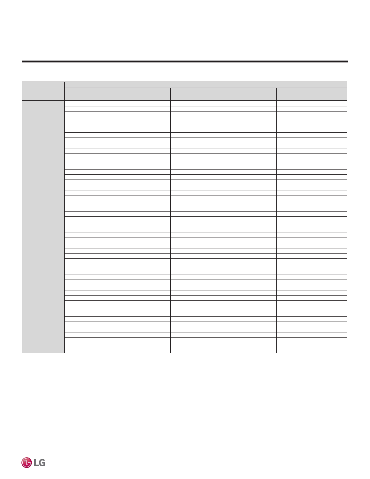
STD. WALL-MOUNTED | 57
Standard Wall-Mounted
Due to our policy of continuous product innovation, some specications may change without notication.
©LG Electronics U.S.A., Inc., Englewood Cliffs, NJ. All rights reserved. “LG” is a registered trademark of LG Corp.
MULTI
F
MAX
MULTI
F
Heating Capacity Table
STANDARD WALL-MOUNTED INDOOR UNITS
Model No. /
Nominal Capacity of
Indoor Unit (Btu/h)
Outdoor Air Temp. Indoor Air Temp. °F DB
°F DB °F WB
61 64 68 70 72 75
TC TC TC TC TC TC
LMN159HVT
15,600
0 -0.4 8.03 7.91 7.84 7.80 7.69 7.35
5 4.5 9.05 8.93 8.86 8.82 8.71 8.37
10 9 10.06 9.95 9.87 9.83 9.72 9.38
17 15 11.42 11.31 11.23 11.19 11.08 10.71
20 19 10.03 11.81 11.73 11.70 11.59 11.19
25 23 12.77 12.66 12.58 12.55 12.43 11.98
30 28 13.51 13.40 13.32 13.28 13.17 12.77
35 32 14.25 14.13 14.06 14.02 13.91 13.57
40 36 14.90 14.79 14.71 14.67 14.56 14.23
45 41 15.56 15.45 15.37 15.34 15.22 14.88
47 43 15.83 15.71 15.64 15.60 15.49 15.15
50 46 16.08 15.97 15.89 15.86 15.74 15.36
55 51 16.51 16.39 16.32 16.28 16.17 15.71
60 56 16.51 16.39 16.32 16.28 16.17 15.78
63 59 16.51 16.39 16.32 16.28 16.17 15.83
68 64 16.51 16.39 16.32 16.28 16.17 15.89
LSN180HSV5
21,600
0 -0.4 11.11 10.96 10.85 10.80 10.64 10.18
5 4.5 12.52 12.37 12.26 12.21 12.06 11.58
10 9 13.93 13.77 13.67 13.61 13.46 12.99
17 15 15.81 15.65 15.55 15.49 15.34 14.84
20 19 16.51 16.36 16.25 16.20 16.04 15.49
25 23 17.69 17.53 17.43 17.37 17.22 16.59
30 28 18.70 18.55 18.44 18.39 18.24 17.69
35 32 19.72 19.56 19.46 19.41 19.25 18.79
40 36 20.63 20.48 20.37 20.32 20.17 19.70
45 41 21.55 21.39 21.29 21.24 21.08 20.61
47 43 21.91 21.76 21.65 21.60 21.44 20.98
50 46 22.26 22.11 22.01 21.95 21.80 21.27
55 51 22.86 22.70 22.59 22.53 22.38 21.76
60 56 22.86 22.70 22.59 22.53 22.38 21.85
63 59 22.86 22.70 22.59 22.53 22.38 21.91
68 64 22.86 22.70 22.59 22.53 22.38 22.02
LMN249HVT
25,600
0 -0.4 13.17 12.99 12.87 12.80 12.61 12.06
5 4.5 14.84 14.66 14.54 14.47 14.29 13.73
10 9 16.51 16.33 16.20 16.14 15.96 15.40
17 15 18.74 18.56 18.42 18.37 18.18 17.59
20 19 19.57 19.39 19.27 19.20 19.01 18.37
25 23 20.96 20.77 20.65 20.59 20.40 19.66
30 28 22.17 21.98 21.85 21.80 21.61 20.96
35 32 23.37 23.19 23.07 23.00 22.82 22.26
40 36 24.45 24.27 24.15 24.08 23.90 23.34
45 41 25.53 25.35 25.23 25.16 24.98 24.42
47 43 25.97 25.79 25.67 25.60 25.41 24.86
50 46 26.39 26.21 26.08 26.02 25.83 25.20
55 51 27.09 26.90 26.78 26.71 26.53 25.79
60 56 27.09 26.90 26.78 26.71 26.53 25.90
63 59 27.09 26.90 26.78 26.71 26.53 25.97
68 64 27.09 26.90 26.78 26.71 26.53 26.08
Table 26: Multi F Standard Wall-Mounted Indoor Units Heating Capacity Table.
TC = Total Capacity (kBtu/h).
Nominal capacity as rated 0 ft. above sea level and a 0 ft. level difference between outdoor and indoor units. Corresponding refrigerant piping length is accordance with standard length of each outdoor unit.
Nominal heating capacity rating obtained with air entering the indoor unit at 70ºF dry bulb (DB) and 60ºF wet bulb (WB), and outdoor ambient conditions of 47ºF dry bulb (DB) and 43ºF wet bulb (WB).
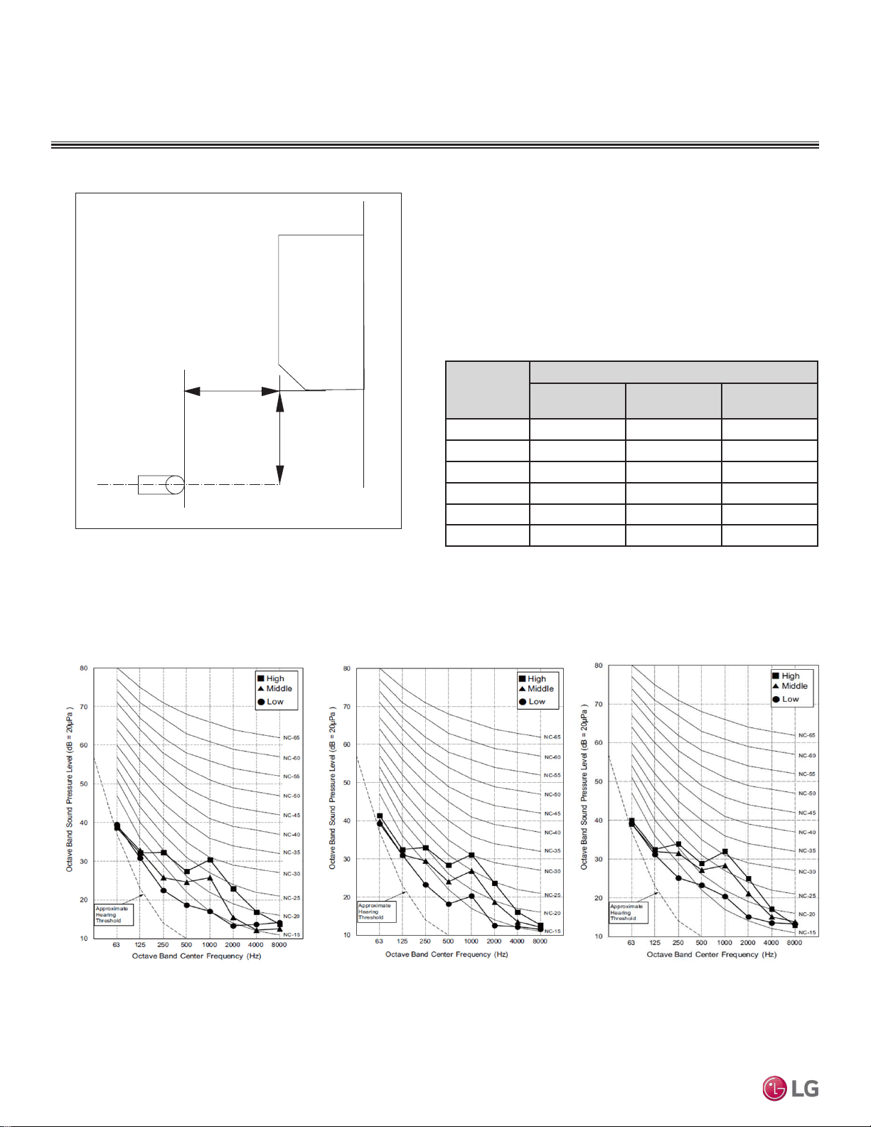
Due to our policy of continuous product innovation, some specications may change without notication.
©LG Electronics U.S.A., Inc., Englewood Cliffs, NJ. All rights reserved. “LG” is a registered trademark of LG Corp.
58 | STD. WALL-MOUNTED
Multi F and Multi F MAX Indoor Unit Engineering Manual
MULTI
F
MAX
MULTI
F
Acoustic Data
STANDARD WALL-MOUNTED INDOOR UNITS
• Measurement taken 2.6′ below the bottom of the unit and at a
distance of 3.3′ from face of unit.
• Measurements taken with no attenuation and units operating at full
load normal operating condition.
• Sound level will vary depending on a range of factors such as
construction (acoustic absorption coefficient) of particular area in
which the equipment is installed.
• Sound power levels are measured in dB(A).
• Tested in anechoic chamber per ISO Standard 3745.
Model No.
Sound Pressure Levels (dB[A]) (Cooling and Heating)
High Fan Speed
Medium Fan
Speed
Low Fan Speed
LMN079HVT 35 31 26
LSN090HSV5 36 32 27
LSN120HSV5 38 34 29
LMN159HVT 42 38 32
LSN180HSV5 44 38 34
LMN249HVT 46 41 36
Figure 63: Sound Pressure Level Measurement Location.
Table 27: Sound Pressure Levels (dB[A]).
2.6 ft.
3.3 ft.
Microphone
Figure 64:LMN079HVT, LSN090HSV5, and LSN120HSV5 Sound Pressure Level Diagrams.
LMN079HVT
LSN090HSV5
LSN120HSV5
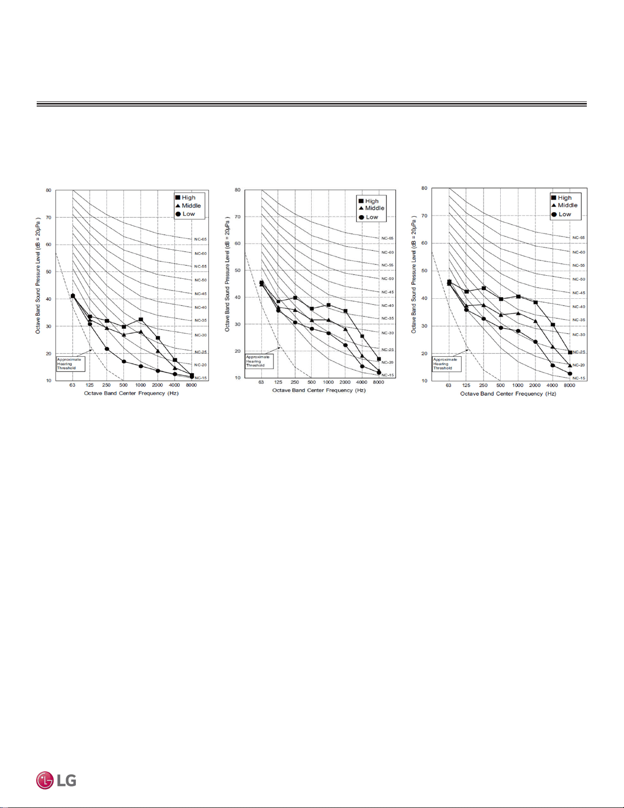
STD. WALL-MOUNTED | 59
Standard Wall-Mounted
Due to our policy of continuous product innovation, some specications may change without notication.
©LG Electronics U.S.A., Inc., Englewood Cliffs, NJ. All rights reserved. “LG” is a registered trademark of LG Corp.
MULTI
F
MAX
MULTI
F
Acoustic Data
STANDARD WALL-MOUNTED INDOOR UNITS
Figure 65:LMN159HVT, LSN180HSV5, and LMN249HVT Sound Pressure Level Diagrams.
LMN159HVT
LSN180HSV5
LMN249HVT
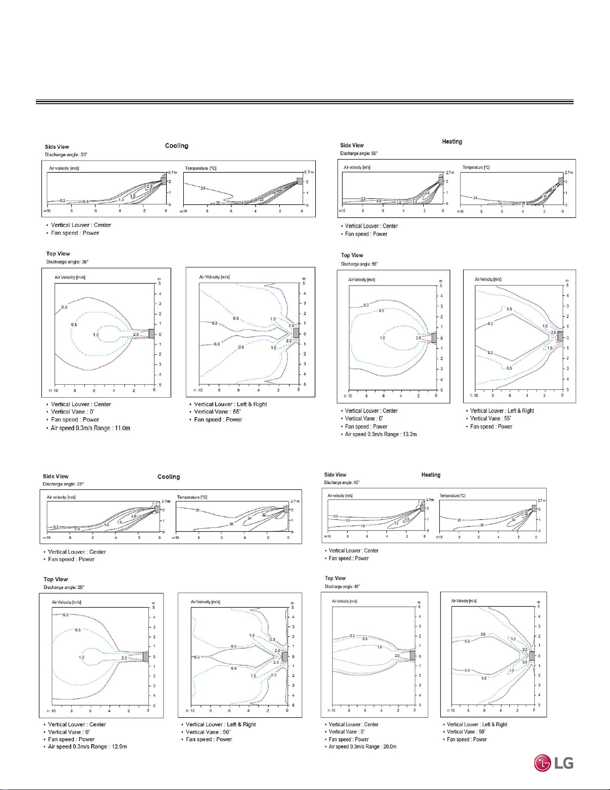
Due to our policy of continuous product innovation, some specications may change without notication.
©LG Electronics U.S.A., Inc., Englewood Cliffs, NJ. All rights reserved. “LG” is a registered trademark of LG Corp.
60 | STD. WALL-MOUNTED
Multi F and Multi F MAX Indoor Unit Engineering Manual
MULTI
F
MAX
MULTI
F
Air Velocity and Temperature Distribution
STANDARD WALL-MOUNTED INDOOR UNITS
Figure 66:LMN079HVT, LSN090HSV5, LSN120HSV5, LMN159HVT Air Velocity and Temperature Distribution Charts.
Figure 67:LSN180HSV5 Air Velocity and Temperature Distribution Charts.
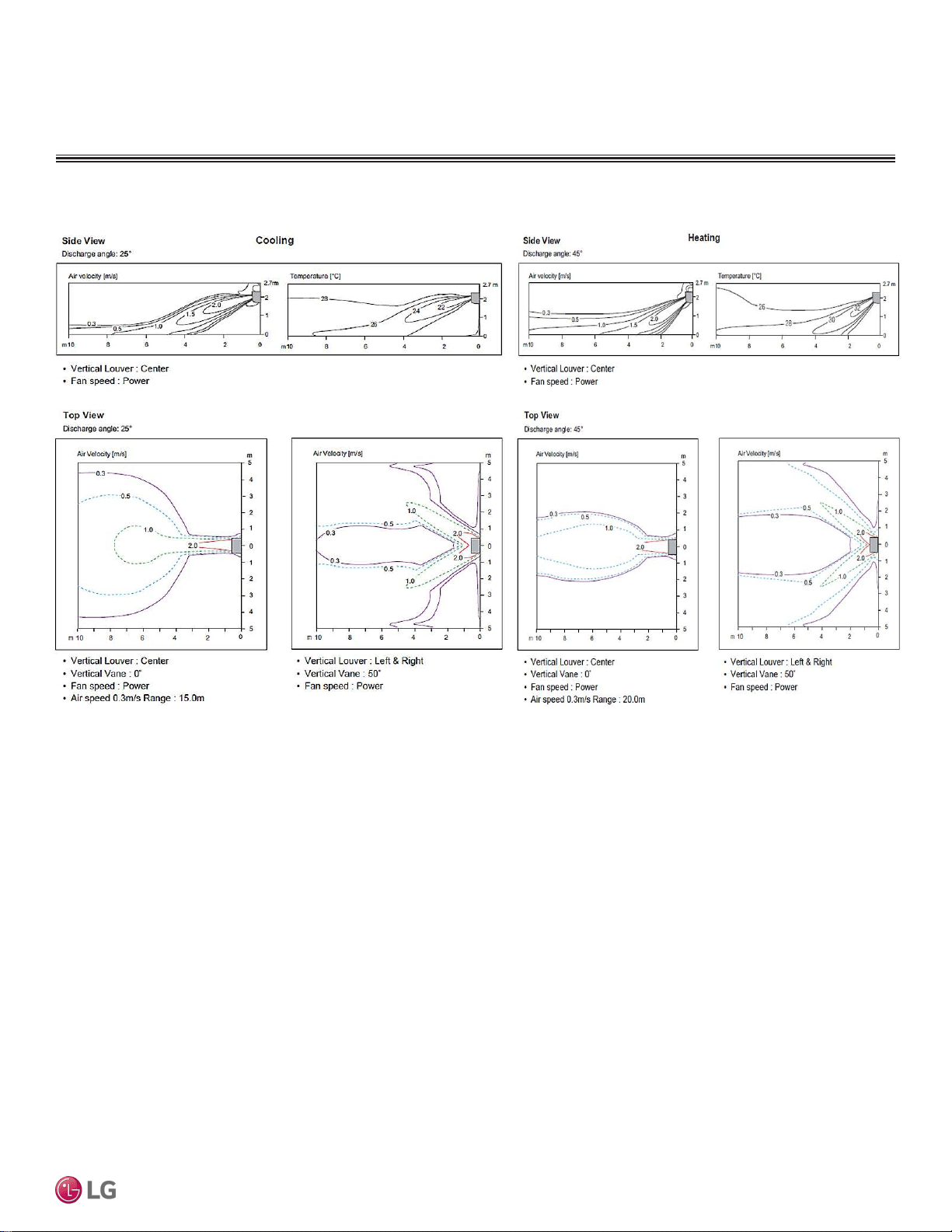
STD. WALL-MOUNTED | 61
Standard Wall-Mounted
Due to our policy of continuous product innovation, some specications may change without notication.
©LG Electronics U.S.A., Inc., Englewood Cliffs, NJ. All rights reserved. “LG” is a registered trademark of LG Corp.
MULTI
F
MAX
MULTI
F
Air Velocity and Temperature Distribution
STANDARD WALL-MOUNTED INDOOR UNITS
Figure 68:LMN249HVT Air Velocity and Temperature Distribution Charts.
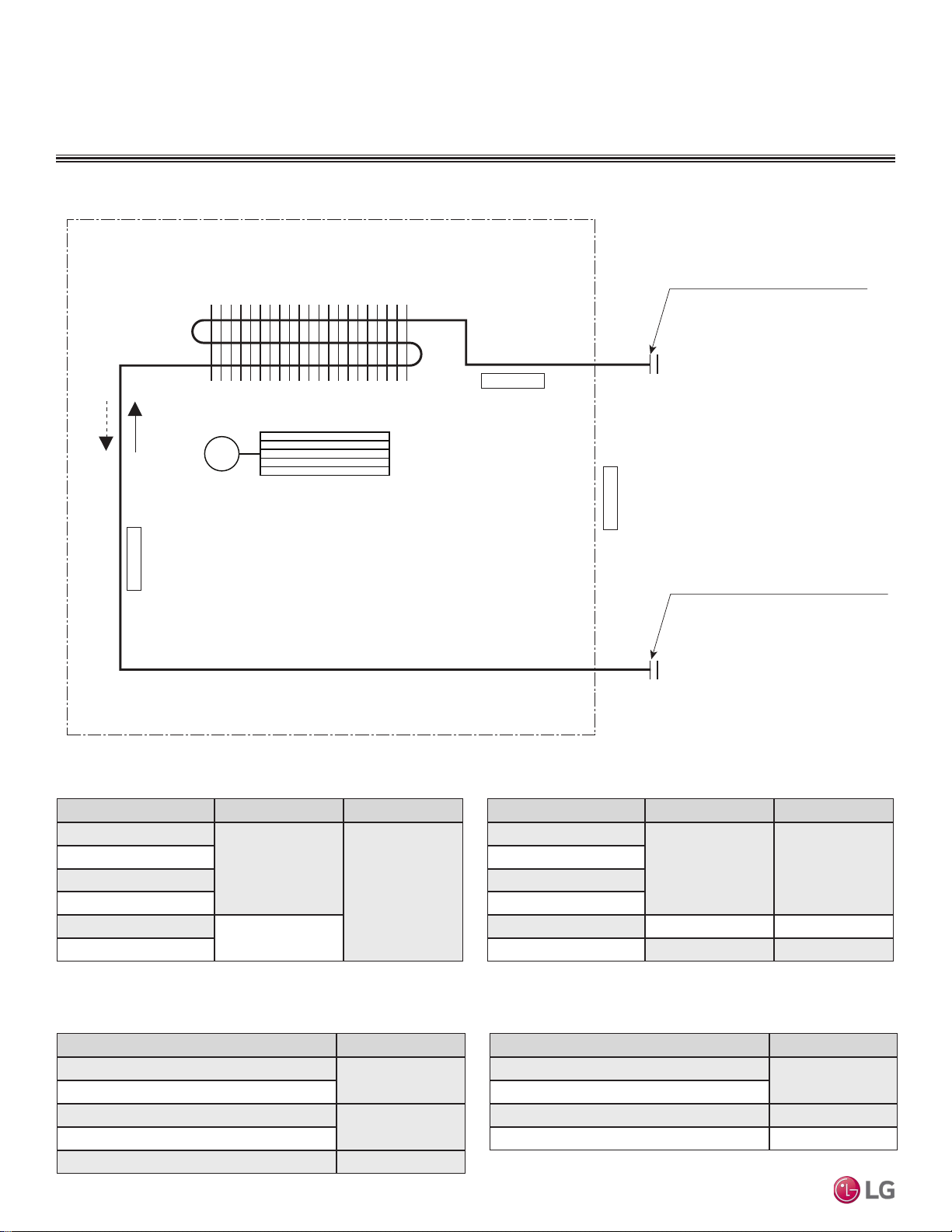
Due to our policy of continuous product innovation, some specications may change without notication.
©LG Electronics U.S.A., Inc., Englewood Cliffs, NJ. All rights reserved. “LG” is a registered trademark of LG Corp.
62 | STD. WALL-MOUNTED
Multi F and Multi F MAX Indoor Unit Engineering Manual
MULTI
F
MAX
MULTI
F
Refrigerant Flow Diagram
STANDARD WALL-MOUNTED INDOOR UNITS
Gas pipe connection port
(flare connection)
Liquid pipe connection port
(flare connection)
Cooling
Heating
Thermistor for
Evaporator Inlet Temperature
Thermistor for
Indoor Air Temperature
Thermistor for Evaporator
Outlet Temperature
Heat Exchanger
Cross Flow Fan
M
Table 28: Multi F Standard Wall-Mounted Indoor Unit
Refrigerant Pipe Sizes.
Model No. Vapor (inch) Liquid (inch)
LMN079HVT
Ø3/8
Ø1/4
LSN090HSV5
LSN120HSV5
LMN159HVT
LSN180HSV5
Ø1/2
LMN249HVT
Table 29: Multi F Standard Wall-Mounted Indoor Unit
Refrigerant Pipe Connections.
Description (Based on Cooling Mode) PCB Connector
Indoor Air Temperature Thermistor
CN-TH1
Evaporator Inlet Temperature Thermistor
Evaporator Middle Temperature Thermistor
CN-TH2
Evaporator Outlet Temperature Thermistor
Water Level Sensor (Optional) CN-TH3
Figure 69:Multi F Standard Wall-Mounted Indoor Unit Refrigerant Flow Diagram.
Table 30: Multi F LSNxxxHSV5 Standard Wall-Mounted Indoor Unit
Thermistor Details.
Model No. Vapor (inch) Liquid (inch)
LMN079HVT
Ø3/8 Ø1/4
LSN090HSV5
LSN120HSV5
LMN159HVT
LSN180HSV5 Ø5/8 Ø3/8
LMN249HVT Ø1/2 Ø1/4
Description (Based on Cooling Mode) PCB Connector
Indoor Air Temperature Thermistor
CN-TH1
Evaporator Inlet Temperature Thermistor
Evaporator Outlet Temperature Thermistor CN-TH2
Water Level Sensor (Optional) CN-TH3
Table 31: Multi F LMNxxxHVT Standard Wall-Mounted Indoor Unit
Thermistor Details.
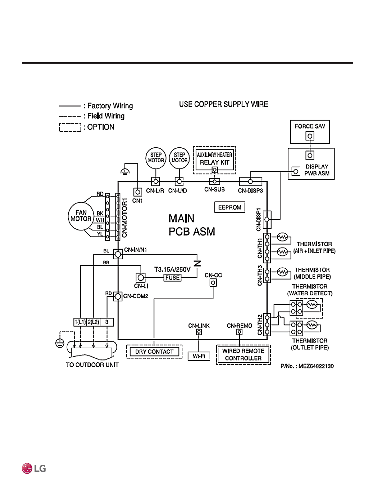
STD. WALL-MOUNTED | 63
Standard Wall-Mounted
Due to our policy of continuous product innovation, some specications may change without notication.
©LG Electronics U.S.A., Inc., Englewood Cliffs, NJ. All rights reserved. “LG” is a registered trademark of LG Corp.
MULTI
F
MAX
MULTI
F
Wiring Diagram
STANDARD WALL-MOUNTED INDOOR UNITS
Figure 70:Multi F Standard Wall-Mounted LSN090HSV5, LSN120HSV5, LSN180HSV5 Indoor Units Wiring Diagram.
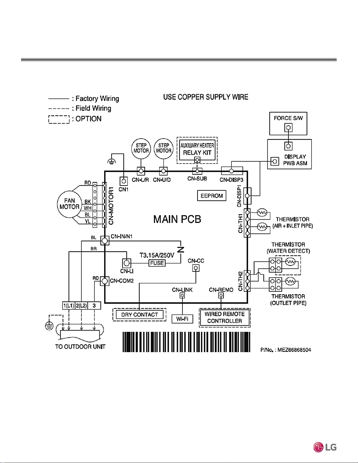
Due to our policy of continuous product innovation, some specications may change without notication.
©LG Electronics U.S.A., Inc., Englewood Cliffs, NJ. All rights reserved. “LG” is a registered trademark of LG Corp.
64 | STD. WALL-MOUNTED
Multi F and Multi F MAX Indoor Unit Engineering Manual
MULTI
F
MAX
MULTI
F
Wiring Diagram
STANDARD WALL-MOUNTED INDOOR UNITS
Figure 71: Multi F Standard Wall-Mounted LMN079HVT, LMN159HVT, LMN249HVT Indoor Unit Wiring Diagram.
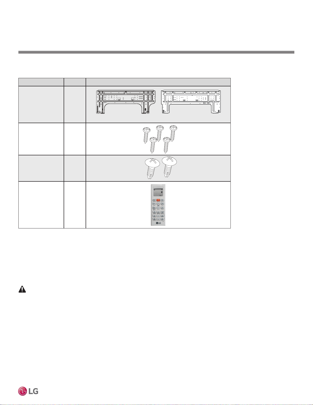
STD. WALL-MOUNTED | 65
Standard Wall-Mounted
Due to our policy of continuous product innovation, some specications may change without notication.
©LG Electronics U.S.A., Inc., Englewood Cliffs, NJ. All rights reserved. “LG” is a registered trademark of LG Corp.
MULTI
F
MAX
MULTI
F
Factory Supplied Parts
Factory Supplied Materials
• Owner’s Manual
• Installation Manual
• Level
• Screwdriver
• Electric drill
• Hole core drill
• Flaring tool set
• Spanner (Half union)
• Thermometer
Factory Supplied Parts and Materials
Table 32: Parts Table.
Required Tools
STANDARD WALL-MOUNTED INDOOR UNITS
Part Quantity Image
Installation Plate One (1)
Type “A” Screws Five (5)
Type “B” Screws
(M4 x 12L)
Two (2)
Wireless
Controller with Holder
AKB74955602
One (1)
7,000 ~ 15,000 Btu/h Indoor Units
18,000 and 24,000 Btu/h Indoor Units
WARNING
Installation work must be performed by trained personnel and in accordance with national wiring standards and all local or other applicable codes.
Improper installation can result in re, electric shock, physical injury, or death.
Note:
Read all instructions before installing this product. Become familiar with the unit’s components and connections, and the order of installation. Incorrect
installation can degrade or prevent proper operation.
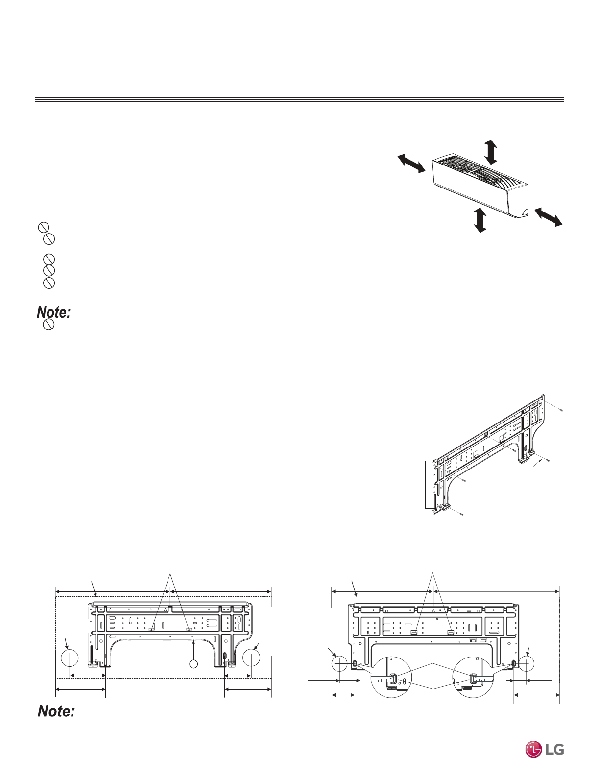
Due to our policy of continuous product innovation, some specications may change without notication.
©LG Electronics U.S.A., Inc., Englewood Cliffs, NJ. All rights reserved. “LG” is a registered trademark of LG Corp.
66 | STD. WALL-MOUNTED
Multi F and Multi F MAX Indoor Unit Engineering Manual
MULTI
F
MAX
MULTI
F
Selecting the Best Location
Do’s
• Place the unit where air circulation will not be blocked.
• Place the unit where drainage can be obtained easily.
• Place the unit where noise prevention is taken into consideration.
• Ensure there is sufficient space from the ceiling and floor.
• Ensure there is sufficient maintenance space.
• Locate the indoor unit where it can be easily connected to the outdoor unit or branch
distribution unit.
Don’ts
• Do not install the unit near a heat or steam source, or where considerable amounts of oil,
iron powder, or flour are used.
• Do not install the unit where sulfuric acid and flammable or corrosive gases are generated, vented into, or stored.
• Do not install the unit near high-frequency generators.
• Do not install the unit near a doorway.
The unit will be damaged, will malfunction, and / or will not operate as designed if installed in any of the conditions listed.
>4 inches
Recommended height
>6-1/2 feet from floor
>4 inches
≥5 inches
Figure 72:Minimum Clearance Requirements.
Installation and Best Layout Practices
Mounting the Installation Plate
The mounting wall must be strong and solid enough to protect the unit from vibration.
• Mount the installation plate on the wall using the Type “A” screws. If mounting the unit on con-
crete, consider using anchor bolts.
• Always mount the installation plate horizontally. Measure the wall and mark the centerline using
thread and a level.
Figure 73:Installation Plate—
Side View.
Installation Plate
Frame
Hooks
Type "A" Screws
Figure 74:Installation Plate for LMN079HVT, LSN090HSV5,
LSN120HSV5, and LMN159HVT Units.
Figure 75:Installation Plate for LSN180HSV5 and LMN249HVT Units.
Ø2-3/4 inches
Ø2-3/4 inches
2-23/32 inches
2-7/32 inches
Right rear
piping
Left rear
piping
Installation Plate
Measuring Tape
Measuring Tape Hanger
Place a level on raised tab
Unit Outline
8-5/32 inches
4-1/8 inches
18-1/8 inches 22-7/16 inches
If the unit is installed near a body of water, certain components are at risk of being corroded. Appropriate anti-corrosion methods must be taken for the
unit and all components.
STANDARD WALL-MOUNTED INDOOR UNITS
Installing in an Area Exposed to Unconditioned Air
In some installation applications, areas (floors, walls) in some rooms will be exposed to
unconditioned air (room will be above or next to an unheated garage or storeroom). To
countermeasure:
• Verify that carpet is or will be installed (carpet will increase the temperature by three degrees).
• Add insulation between the floor joists.
• Install radiant heat or another type of heating system to the floor.
Ø2-9/16
5-3/16 3-11/16
Right rear piping
Left rear piping
Place a level on raised tab
Unit Outline
8-1/2
6-7/8
17-3/8 17-3/8
5
Ø2-9/16
• Indoor units (IDUs) must not be placed in an environment where the IDUs will be exposed to harmful volatile organic compounds (VOCs)
or in environments where there is improper air make up or supply or inadequate ventilation. If there are concerns about VOCs in the envi-
ronment where the IDUs are installed, proper air make up or supply and/or adequate ventilation must be provided. Additionally, in buildings
where IDUs will be exposed to VOCs, consider a third party factory-applied epoxy coating to the fan coils for each IDU where the entire coil
is dipped, not sprayed.
• If the unit is installed near a body of water, the installation parts are at risk of corroding. Appropriate anti-corrosion methods must be taken for
the unit and all installation parts.
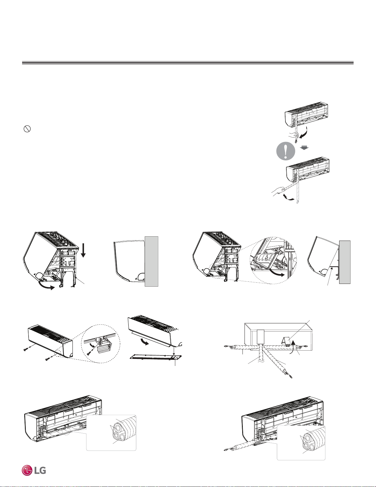
STD. WALL-MOUNTED | 67
Standard Wall-Mounted
Due to our policy of continuous product innovation, some specications may change without notication.
©LG Electronics U.S.A., Inc., Englewood Cliffs, NJ. All rights reserved. “LG” is a registered trademark of LG Corp.
MULTI
F
MAX
MULTI
F
Installation and Best Layout Practices
Hanging the Indoor Unit Frame
1. Attach the three (3) hooks on the top of the indoor unit to the top edge of the instal-
lation plate. Verify the hooks are properly attached to the installation plate by gently
shaking the indoor unit from side to side.
2. Unlock the tubing clamp from the indoor unit frame. For easier access between the
bottom of the indoor unit and the wall, prop the clamp between the indoor unit frame
and installation plate.
3. Remove the screw covers at the bottom of the indoor unit, unscrew the two (2) screws,
remove the frame cover, remove the piping connection cover, and position the piping
for installation (down, back, left, or right).
Preparing for Installation
Prepare the refrigerant piping and drain hose (indoor unit piping) for installation through the
wall: press on the top of the tubing clamp and slowly guide the piping / hose down (depending
on installation requirements, then to the left or right). Relock the tubing clamp after the piping /
hose are released.
Note:
Do not bend the piping / drain hose from side to side; it will damage the components.
Figure 76:Preparing for Installation.
Installation plate
Figure 77:Locking the Indoor Unit onto the Installation Plate.
Tubing Clamp
Figure 78:Accessing the Back of the Indoor Unit.
Right
Tubing Clamp
Down
Left
Back
Frame Cover
Figure 79:Removing the Frame Cover.
Figure 80:Exterior Back View of Indoor Unit.
Figure 81:Piping Installed to the Left.
Figure 82:Piping Installed to the Right.
Connecting
pipe
Tape
Drain hose
Connecting
pipe
Tape
Drain hose
STANDARD WALL-MOUNTED INDOOR UNITS
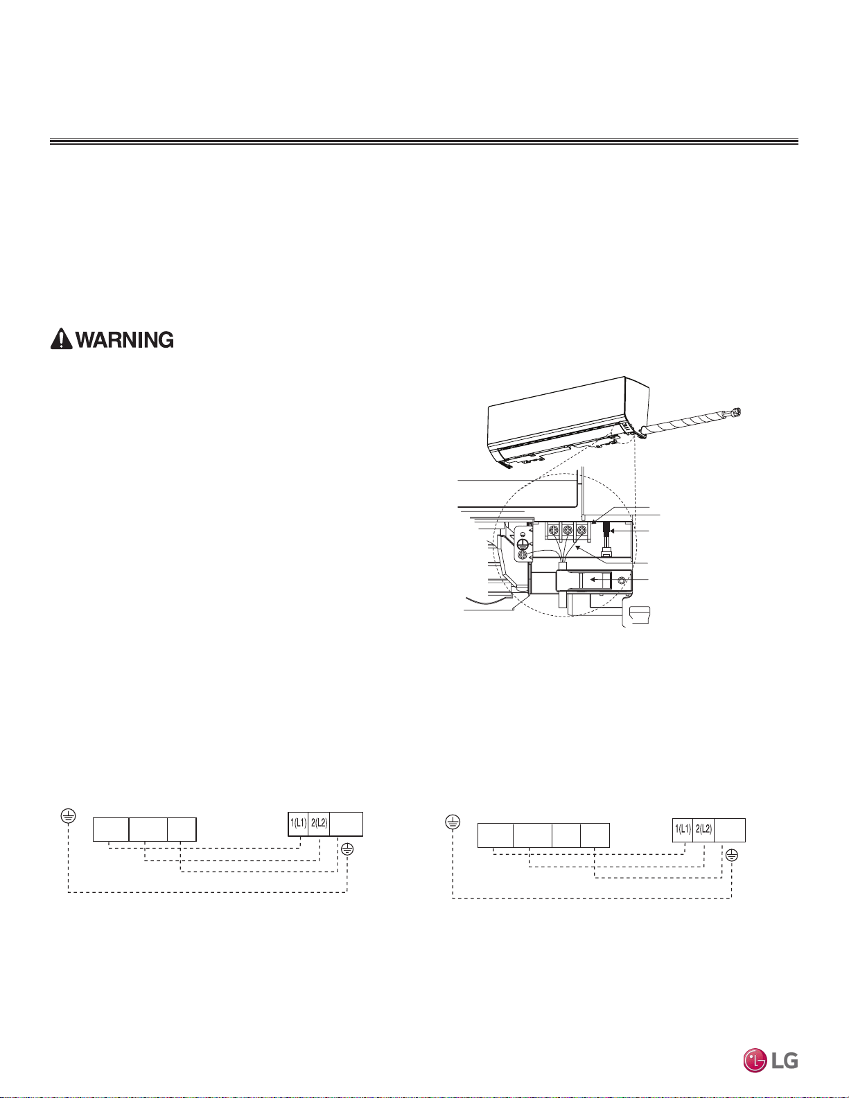
Due to our policy of continuous product innovation, some specications may change without notication.
©LG Electronics U.S.A., Inc., Englewood Cliffs, NJ. All rights reserved. “LG” is a registered trademark of LG Corp.
68 | STD. WALL-MOUNTED
Multi F and Multi F MAX Indoor Unit Engineering Manual
MULTI
F
MAX
MULTI
F
Installation and Best Layout Practices
Power Wiring / Communications Cable Guidelines
STANDARD WALL-MOUNTED INDOOR UNITS
• Follow manufacturer’s circuit diagrams in the technical manuals.
• Confirm power source specifications.
• Confirm that the electrical capacity is sufficient.
• Starting current must be maintained ±10 percent of the rated current marked on the outdoor unit name plate.
• Confirm cable thickness specifications.
• It is required that a circuit breaker is installed, especially if conditions could become wet or moist.
• Include a disconnect in the power wiring system, add an air gap contact separation of at least 1/8 inch in each active (phase) conductor.
Terminal block
Power wiring /
communications cable
Wired Remote Controlle
r
Terminal (Optional)
Cable restraint
Figure 83: Connecting Power Wiring / Communications Cable.
Connect Power Wiring and
Communications Cable
1. Insert the power wiring / communications cable from the outdoor
unit or branch distribution unit (Multi F MAX systems only) through
the bottom of the indoor unit.
2. Connect each wire to its appropriate terminal on the indoor unit
control board. Verify that the color and terminal numbers from the
outdoor unit or branch distribution unit (Multi F MAX systems only)
wiring match the color and terminal numbers on the indoor unit.
3. Secure power wiring/communications cable with cable restraint.
Figure 84:Simplied View of Indoor Unit to Outdoor Unit / Branch
Distribution Unit Terminal Connections—LMN079HVT, LSN090HSV5,
LSN120HSV5 and LMN159HVT.
Figure 85:Simplied View of Indoor Unit to Outdoor Unit / Branch
Distribution Unit Terminal Connections— LSN180HSV5 and
LMN249HVT.
Indoor Unit Terminal Block
GND
Outdoor Unit Terminal Block or
Branch Distribution Unit Terminal Block
(Multi F MAX Systems Only)
GND
GRN / YLW
BR
BL
RD
3 or S
32(L2)1(L1)
Indoor Unit Terminal Block
1(L1 )2(L2)
GND
Outdoor Unit Terminal Block or
Branch Distribution Unit Terminal Block
(Multi F MAX Systems Only)
GND
GRN / YLW
BR
BL
RD
3
3 or S
• Loose wiring will cause unit to malfunction, overheat, and catch
fire, resulting in severe injury or death.
Note:
• Terminal screws will become loose during transport. Properly
tighten the terminal connections during installation.
A voltage drop will cause the following problems:
• Magnetic switch vibration, fuse breaks, or disturbance to the
normal function of an overload protection device.
• Compressor will not receive the proper starting current.
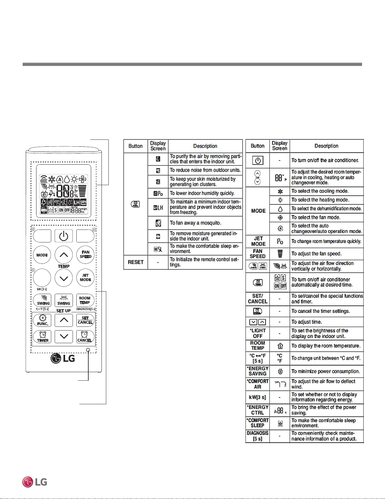
STD. WALL-MOUNTED | 69
Standard Wall-Mounted
Due to our policy of continuous product innovation, some specications may change without notication.
©LG Electronics U.S.A., Inc., Englewood Cliffs, NJ. All rights reserved. “LG” is a registered trademark of LG Corp.
MULTI
F
MAX
MULTI
F
STANDARD WALL-MOUNTED INDOOR UNITS
Installation and Best Layout Practices
Controller Options
Standard wall-mounted indoor units include a wireless controller (AKB74955602), but optional LG-supplied wired controllers are available.
Wireless Controller
Table 33: AKB74955602 Wireless Controller Functions.Figure 86:AKB74955602 Wireless Controller.
Screen Display
Buttons
*
*
*
RESET
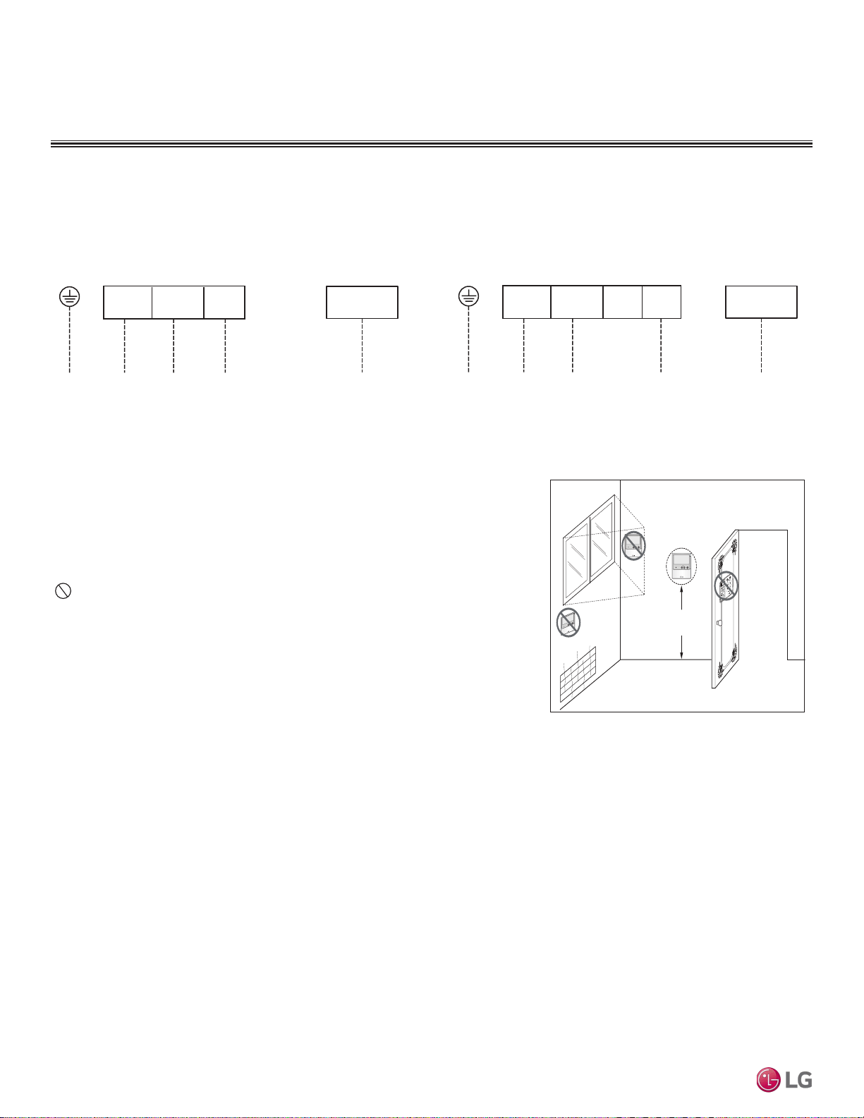
Due to our policy of continuous product innovation, some specications may change without notication.
©LG Electronics U.S.A., Inc., Englewood Cliffs, NJ. All rights reserved. “LG” is a registered trademark of LG Corp.
70 | STD. WALL-MOUNTED
Multi F and Multi F MAX Indoor Unit Engineering Manual
MULTI
F
MAX
MULTI
F
4 to 5 feet
above the floor
NO
NO
NO
YES
Remote Controller
TEMP
Remote Controller
TEMP
Re
m
ote C
o
nt
roller
TEMP
Installation and Best Layout Practices
STANDARD WALL-MOUNTED INDOOR UNITS
Wired Controller Connections
Figure 87:Wired Controller Connection on Indoor Unit Terminal Block—
LMN079HVT, LSN090HSV5, LSN120HSV5, and LMN159HVT Models.
Figure 88:Wired Controller Connection on Indoor Unit Terminal Block—
LSN180HSV5 and LMN249HVT Models.
Figure 89:Proper Location for the Wired Controller.
Wired controllers include a sensor to detect room temperature. To maintain comfort
levels in the conditioned space, the wired controller must be installed in a location away
from direct sunlight, high humidity, and where it could be directly exposed to cold air.
Controller must be installed four (4) to five (5) feet above the floor where its LED display
can be read easily, in an area with good air circulation, and where it can detect an aver-
age room temperature.
Do not install the wired controller near or in:
• Drafts or dead spots behind doors and in corners
• Hot or cold air from ducts
• Radiant heat from the sun or appliances
• Concealed pipes and chimneys
• An area where temperatures are uncontrolled, such as an outside wall
Wired Controller Placement
Indoor Unit Terminal Block
1(L1 )2(L2)
GND
GRN / YLW
BR
BL
RD
CN-REMO
To Outdoor Unit or Branch Distribution Unit
(Multi F MAX Systems Only)
To Wired Controller
3
Indoor Unit Terminal Block
1(L1 )2(L2)
GND
GRN / YLW
BR
BL
RD
CN-REMO
To Outdoor Unit or Branch Distribution Unit
(Multi F MAX Systems Only)
To Wired Controller
3

STD. WALL-MOUNTED | 71
Standard Wall-Mounted
Due to our policy of continuous product innovation, some specications may change without notication.
©LG Electronics U.S.A., Inc., Englewood Cliffs, NJ. All rights reserved. “LG” is a registered trademark of LG Corp.
MULTI
F
MAX
MULTI
F
Hanging the Wired Controller
1. The controller wiring / cable can be installed in one of three direc-
tions: top, back, or on the right side. If top or right side installation
is desired, remove cable guide grooves on the controller, and
then position wiring / cable on applicable side.
2. Choose and mark the area of installation. Use the provided parts
and screw the wall plate into place. Install the controller wall plate
to fit the electrical box if one is present. Ensure that no gaps exist
between the wall plate and the wall itself.
3. Arrange wiring / cables so as not to interfere with the controller
circuitry. Position the wired controller on the wall plate. Snap into
place by pressing the bottom part of the wired controller onto
the wall plate. Make sure that no gaps exist between the wired
controller and the wall plate on all sides.
4. To remove wired controller from the wall plate, insert a screw-
driver into the two holes at the bottom. Twist screwdriver to
release controller. Do not damage the controller components
when removing.
Back
Top
Top
Right
Side
Right
Side
Wall Wall
Wall Wall
Installing the Controller
Removing the Controller
Figure 91:Removing the Cable Guide Grooves.
Figure 92:Attaching the Wall Plate.
Figure 93:Installing / Removing
the Controller.
Finalizing Indoor Unit Installation
1. Move the tubing clamp to its original position.
2. Ensure the three (3) hooks are properly attached to the installa-
tion plate by gently shaking the indoor unit from side to side.
3. Press the bottom left and right sides of the indoor unit against the
installation plate until the hooks click firmly into their slots.
4. Using two (2) Type “C” screws, secure the bottom of the indoor
unit to the installation plate.
5. Remove the two (2) tabs from the filter.
6. Replace the frame cover.
Type 'C' screws
Figure 90:Attach Bottom of Indoor Unit to Installation Plate.
STANDARD WALL-MOUNTED INDOOR UNITS
Installation and Best Layout Practices
Assigning the Thermistor for Temperature Detection
Each indoor unit includes a return air thermistor assigned to sense the temperature. If a wired controller is installed, there is a choice of
sensing temperature with either the indoor unit return air thermistor or the thermistor in the wired controller. It is also an option to set both
thermistors to sense temperature so that indoor unit bases its operation on the first thermistor to reach the designated temperature differen-
tial. For applicable indoor units, an optional Remote Temperature Sensor can be used in lieu of the return air thermistor—either alone or in
conjunction with a wired controller thermistor as previously described.
Figure 94:Removing the Filter Tabs.
Filter

“Mechanical Specifications” on page 73
“General Data / Specifications” on page 74
“Dimensions” on page 75
“Cooling Capacity Table” on page 76
“Heating Capacity Table” on page 78
“Acoustic Data” on page 79
“Air Velocity and Temperature Distribution” on page 81
“Refrigerant Flow Diagram” on page 82
“Wiring Diagram” on page 83
“Factory Supplied Parts and Materials” on page 84
“Installation and Best Layout Practices” on page 85
LOW
WALL CONSOLE
INDOOR UNIT DATA

STD. WALL-MOUNTED | 73
Low Wall Console
Due to our policy of continuous product innovation, some specications may change without notication.
©LG Electronics U.S.A., Inc., Englewood Cliffs, NJ. All rights reserved. “LG” is a registered trademark of LG Corp.
MULTI
F
MAX
MULTI
F
LOW WALL CONSOLE INDOOR UNITS
Mechanical Specications and Features
Low Wall Console Indoor Units
General
All LG indoor units are factory assembled, wired, piped, and provided
with a control circuit board, fan, and motor. Low Wall Console units
have a sound rating no higher than 44 dB(A) as tested per KSA0701
ISO Low 3745.
Coil
Indoor unit coils are comprised of a minimum of two rows of
aluminum fins mechanically bonded to copper tubing. The coils are
pressure tested at the factory. Each unit is provided with a factory
installed condensate drain pan below the coil.
Refrigerant System
The system is designed for use with R410A refrigerant. The refrig-
eration circuit is pressure-tested at the factory and shipped with a
holding charge of helium gas. Refrigerant pipe connections are 45°
flare. All refrigerant lines from the outdoor unit to the indoor units
must be field insulated.
Electrical
The indoor units require 208–230Vac/60Hz/1Φ power with voltage
variance of no more than ±10%.
Casing
The units mount on a vertical surface. They are shipped with a sepa-
rate back plate that secures the unit to the wall, protruding no more
than nine (9) inches. Refrigerant piping can be installed in one (1) of
four (4) different directions.
Finish
The Low Wall Console unit has a case with a beige-white panel. It
is manufactured of heavy-duty acrylonitrile butadiene styrene (ABS)
and high impact polystyrene (HIPS) plastic.
Fan Assembly and Control
The unit has a single, direct-drive, turbo fan made of high strength
ABS plastic. The fan motor is brushless digitally controlled (BLDC)
with permanently lubricated and sealed ball bearings. The fan / motor
assembly is mounted on vibration attenuating rubber grommets. Fan
speed is controlled using a microprocessor-based direct digitally
controlled algorithm that provides pre-programmed, eld-selectable
xed or auto fan speeds in the Heating and Cooling modes. For Low
Wall Console units, the indoor fan has Low, Med, High, Jet Cool, and
Auto settings for Cooling mode; and has Low, Med, High, Jet Heat,
and Auto settings for Heating mode. The Auto setting adjusts the
fan speed based on the difference between the controller setpoint
and space temperature. Also, the separate Chaos setting provides a
simultaneous and random change in fan speed and ow direction at
the discharge, simulating a natural outdoor breeze.
Air Filter
The return air inlet
has a factory-
supplied primary
removable, washable
filter. The filter is ac-
cessed from the front
of the unit without the
use of tools.
Airflow Guide
Vanes
A factory-installed
motorized guide vane controls the direction of airflow up and down
for uniform air distribution. Side to side control is manual.
Microprocessor Control
The indoor unit has an integrated control panel to communicate with
the outdoor unit. All unit operation parameters are stored in non-vola-
tile memory resident on the unit microprocessor. The microprocessor
controls space temperature through using the value provided by the
temperature sensors within the indoor unit. The microprocessor con-
trol will activate indoor unit operation when the indoor room tempera-
ture falls below or rises above a setpoint temperature, at which point,
a signal is sent to the outdoor unit to begin the appropriate mode. The
microprocessor also provides self-diagnostics and auto restart func-
tions. A eld-supplied four-wire power / communications cable must
be installed to connect the indoor unit(s) to the outdoor unit.
Controls
The indoor unit casing has an integral infrared sensor to communi-
cate with the supplied LG wireless handheld remote controller. An
optional LG supplied wired controller is available as an additional
accessory. Communication between the indoor units and the outdoor
unit is accomplished through 14 AWG, four-core, stranded and
shielded power / communication cable. The indoor unit has an option
for wi-fi and can be controlled with LG’s SmartThinQ app on a smart
device. A field-supplied wi-fi network and smart device are required.
The SmartThinQ app is free and is available for Android and iOS
smart devices.
Condensate
The unit is designed for gravity draining of condensate and includes
a flexible drain hose capable of installation in one of two directions.
The unit also includes a connection that is compatible with the Aqua-
Guard
®
AG-9300-LG condensate sensor.
• Inverter (Variable speed fan)
• Comfort Air
• Jet cool/Jet Heat
• Group control
• Auto operation
• Auto restart operation
• Optional wi-fi
• Self-diagnostic function
• Wireless LCD remote control included
Features
Figure 95: Multi F Low Wall Console Indoor Unit.
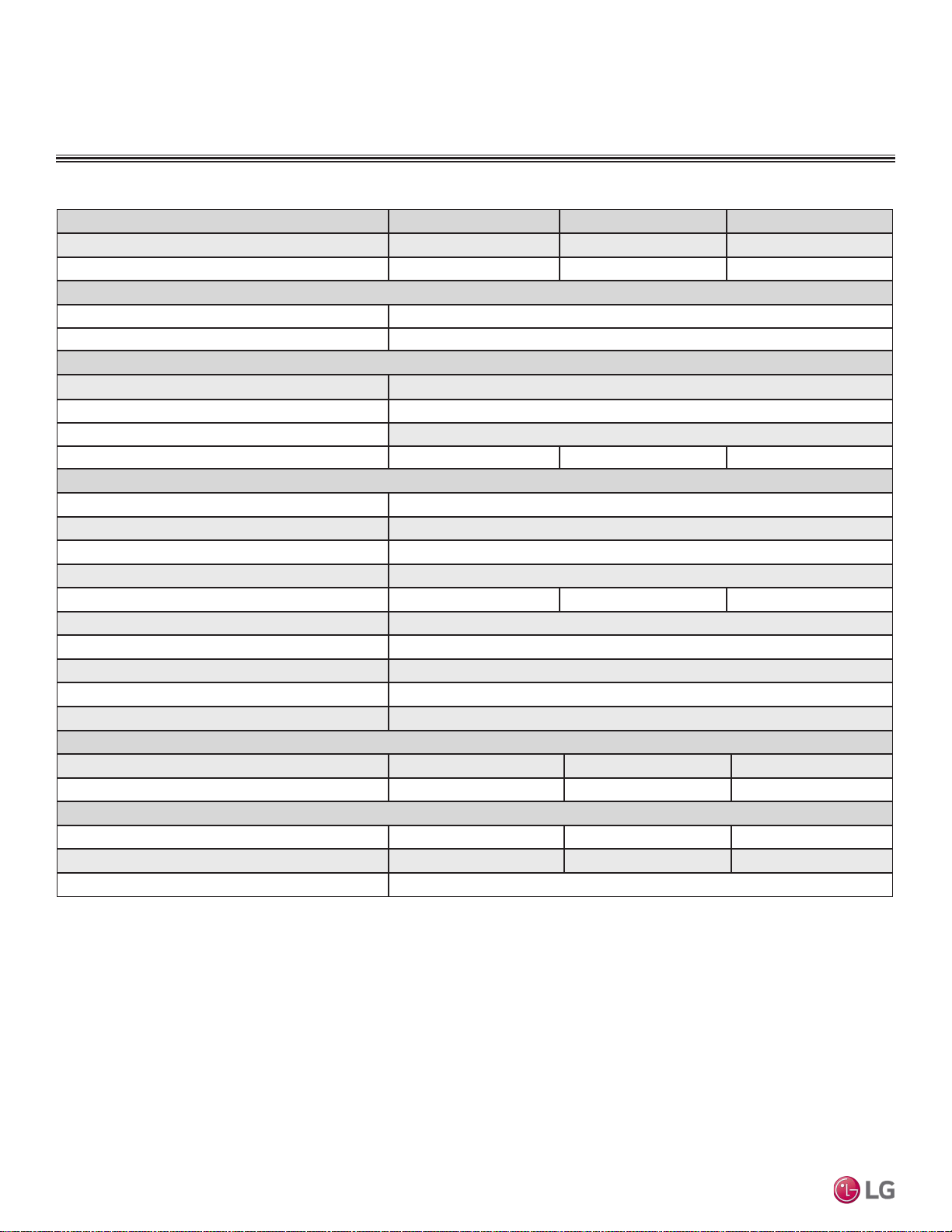
Due to our policy of continuous product innovation, some specications may change without notication.
©LG Electronics U.S.A., Inc., Englewood Cliffs, NJ. All rights reserved. “LG” is a registered trademark of LG Corp.
74 | STD. WALL-MOUNTED
Multi F and Multi F MAX Indoor Unit Engineering Manual
MULTI
F
MAX
MULTI
F
General Data / Specications
Model Name LQN090HV4 LQN120HV4 LMQN150HV
Nominal Cooling Capacity (Btu/h)
1
9,000 12,000 15,710
Nominal Heating Capacity (Btu/h)
1
10,500 13,650 17,070
Operating Range
Cooling (°F WB)
57-77
Heating (°F DB)
59-81
Fan
Type
Turbo
Motor Output (W) x Qty.
48 x 1
Motor/Drive
Brushless Digitally Controlled / Direct
Airflow Rate CFM (Max/H/M/L)
304 / 300 / 237 / 177 346 / 318 / 244 / 184 388 / 357 / 304 / 254
Unit Data
Refrigerant Type
2
R410A
Refrigerant Control
EEV
Power Supply V, Ø, Hz
3
208-230, 1, 60
Rated Amps (A)
0.7
Sound Pressure Level dB(A) (H/M/L)
4
38/32/27 39/32/27 44/39/35
Dimensions (W x H x D, in.)
27-9/16 x 23-5/8 x 8-9/32
Net Unit Weight (lbs.)
35.7
Shipping Weight (lbs.)
41.7
Power Wiring / Communications Cable (No. x AWG)
5
4 x 14
Heat Exchanger (Row x Column x FPI ) x Qty.
(2 x 19 x 19 ) x 1
Pipe Size
Liquid (in.)
1/4 1/4 1/4
Vapor (in.)
3/8 3/8 1/2
Connection Size
Liquid (in.)
1/4 1/4 1/4
Vapor (in.)
3/8 3/8 1/2
Drain O.D. / I.D. (in.)
27/32, 5/8
Table 34: Multi F Low Wall Console Indoor Unit General Data.
LOW WALL CONSOLE INDOOR UNITS
1
Nominal capacity is rated 0 ft. above sea level with corresponding refrigerant piping length in
accordance with low length of each outdoor unit and a 0 ft. level difference between outdoor and indoor
units. All capacities are net with a combination ratio between 95 – 105%.
Nominal cooling capacity rating obtained with air entering the indoor unit at 80ºF dry bulb (DB) and 67ºF
wet bulb (WB) and outdoor ambient conditions of 95ºF dry bulb (DB) and 75ºF wet bulb (WB).
Nominal heating capacity rating obtained with air entering the indoor unit at 70ºF dry bulb (DB) and 60ºF
wet bulb (WB) and outdoor ambient conditions of 47ºF dry bulb (DB) and 43ºF wet bulb (WB).
2
This unit comes with a dry helium charge.
3
Acceptable operating voltage: 187V-253V.
4
Sound pressure levels are tested in an anechoic chamber under ISO Low 3745 and are the same in
both cooling and heating mode. These values can increase due to ambient conditions during operation.
5
All power wiring / communications cable to the IDUs be minimum 14 AWG, 4-conductor, stranded,
shielded or unshielded (if shielded, must be grounded to chassis at ODU only) and must comply with
applicable local and national codes.
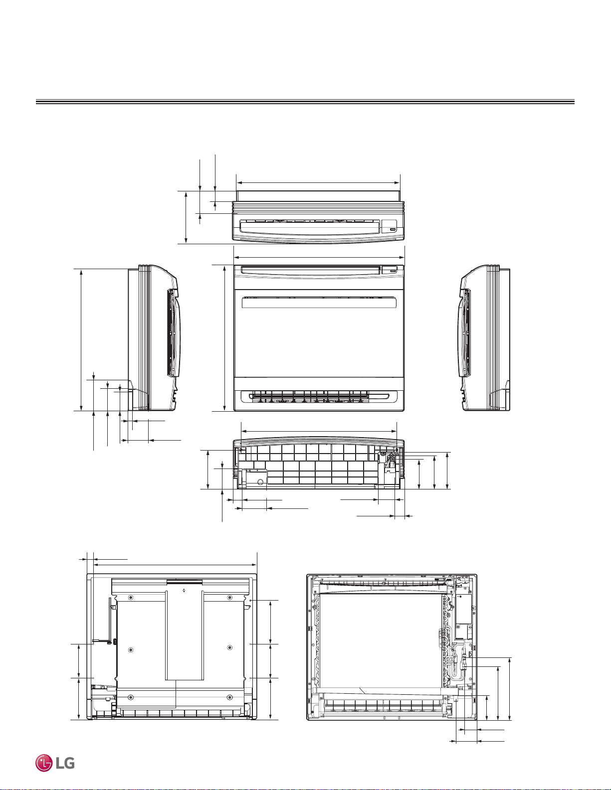
STD. WALL-MOUNTED | 75
Low Wall Console
Due to our policy of continuous product innovation, some specications may change without notication.
©LG Electronics U.S.A., Inc., Englewood Cliffs, NJ. All rights reserved. “LG” is a registered trademark of LG Corp.
MULTI
F
MAX
MULTI
F
Dimensions
LOW WALL CONSOLE INDOOR UNITS
Figure 96: LQN090HV4, LQN120HV4, and LMQN150HV Dimensions.
23 (584)
4-29/32 (125)
3-17/32 (90)
23-5/8 (600)
6-5/16 (160)
3-5/32 (80)
3-15/16 (100)
25-5/32 (639)
27-9/16 (700)
26-7/32 (666)
8-9/32 (210)
3-3/4 (95)
1-25/32 (45)
3-5/32 (80)
3-1/4 (82.5)
2-11/16 (68.5)
5-29/32 (150)
1-15/32 (37)
5-1/2 (140)
4-23/32 (120)
23/32 (18)23/32 (18)
1-15/32 (37)
1-15/32 (37)
10-1/4 (260.5)
8-21/32 (220)
4-1/16 (103)
2-1/32 (51)
3-7/16 (87)
7-3/32 (180)
25-15/32 (647)
1-1/32 (26.5)
5-1/2 (140)6-11/16 (170)
5-1/2 (140)6-11/16 (170)
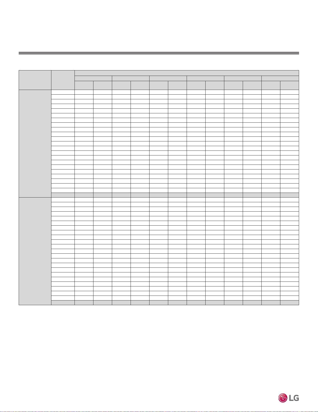
Due to our policy of continuous product innovation, some specications may change without notication.
©LG Electronics U.S.A., Inc., Englewood Cliffs, NJ. All rights reserved. “LG” is a registered trademark of LG Corp.
76 | STD. WALL-MOUNTED
Multi F and Multi F MAX Indoor Unit Engineering Manual
MULTI
F
MAX
MULTI
F
Cooling Capacity Table
LOW WALL CONSOLE INDOOR UNITS
Table 35: Multi F Low Wall Console Indoor Units Cooling Capacity Table.
Model No. /
Nominal Capacity
of Indoor Unit
(Btu/h)
Outdoor Air
Temp.
(°F DB)
Indoor Air Temp. °F DB / °F WB
68 / 57 73 / 61 77 / 64 80 / 67 86 / 72 90 / 75
TC SHC TC SHC TC SHC TC SHC TC SHC TC SHC
LQN090HV4
9,000
14 8.82 6.19 9.37 6.54 9.92 6.33 10.31 6.47 11.01 6.52 11.56 6.65
20 8.82 6.24 9.36 6.59 9.91 6.38 10.31 6.52 11.01 6.57 11.55 6.70
25 8.81 6.29 9.36 6.64 9.90 6.43 10.30 6.57 11.00 6.62 11.54 6.75
30 8.80 6.34 9.35 6.70 9.90 6.48 10.29 6.62 10.99 6.68 11.54 6.80
35 8.80 6.39 9.34 6.75 9.89 6.53 10.28 6.67 10.98 6.73 11.53 6.85
40 8.79 6.43 9.33 6.80 9.88 6.58 10.27 6.72 10.97 6.78 11.52 6.90
45 8.78 6.48 9.33 6.85 9.87 6.63 10.27 6.77 10.96 6.83 11.51 6.96
50 8.78 6.53 9.32 6.90 9.87 6.68 10.26 6.82 10.96 6.88 11.50 7.01
55 8.77 6.58 9.31 6.95 9.86 6.73 10.25 6.87 10.95 6.93 11.49 7.06
60 8.76 6.63 9.31 7.00 9.85 6.78 10.24 6.92 10.94 6.98 11.48 7.11
65 8.76 6.67 9.30 7.05 9.84 6.83 10.24 6.97 10.93 7.03 11.47 7.16
70 8.75 6.72 9.29 7.10 9.84 6.87 10.23 7.02 10.92 7.08 11.47 7.21
75 8.54 6.61 9.08 6.99 9.62 6.78 10.01 6.93 10.71 6.99 11.25 7.13
80 8.33 6.50 8.87 6.88 9.41 6.68 9.80 6.83 10.49 6.90 11.03 7.05
85 8.12 6.38 8.66 6.77 9.20 6.58 9.59 6.73 10.28 6.81 10.82 6.96
90 7.91 6.26 8.45 6.65 8.99 6.47 9.37 6.63 10.06 6.72 10.60 6.87
95 7.68 6.19 8.22 6.59 8.75 6.42 9.00 6.48 9.83 6.68 10.36 6.84
100 7.50 6.03 8.03 6.42 8.57 6.27 8.88 6.38 9.64 6.54 10.17 6.70
105 7.31 5.86 7.84 6.26 8.38 6.11 8.77 6.28 9.45 6.39 9.99 6.56
110 7.12 5.66 7.66 6.05 8.19 5.92 8.58 6.09 9.26 6.21 9.80 6.38
115 6.94 5.49 7.47 5.88 8.01 5.77 8.39 5.94 9.08 6.06 9.61 6.23
118 6.82 5.45 7.36 5.85 7.89 5.74 8.28 5.91 8.96 6.04 9.50 6.22
122 6.79 5.44 7.32 5.84 7.86 5.73 8.24 5.90 8.93 6.04 9.46 6.21
LQN120HV4
12,000
14 11.76 8.37 12.49 8.84 13.22 8.56 13.75 8.74 14.69 8.82 15.42 8.98
20 11.75 8.44 12.48 8.91 13.21 8.63 13.74 8.81 14.67 8.89 15.40 9.05
25 11.75 8.50 12.48 8.98 13.20 8.70 13.73 8.88 14.66 8.96 15.39 9.12
30 11.74 8.57 12.47 9.05 13.19 8.76 13.72 8.95 14.65 9.02 15.38 9.19
35 11.73 8.63 12.46 9.12 13.18 8.83 13.71 9.02 14.64 9.09 15.37 9.26
40 11.72 8.70 12.45 9.19 13.17 8.90 13.70 9.08 14.63 9.16 15.36 9.33
45 11.71 8.76 12.44 9.26 13.16 8.96 13.69 9.15 14.62 9.23 15.35 9.40
50 11.70 8.83 12.43 9.33 13.15 9.03 13.68 9.22 14.61 9.30 15.33 9.47
55 11.69 8.89 12.42 9.39 13.14 9.10 13.67 9.29 14.60 9.37 15.32 9.54
60 11.68 8.96 12.41 9.46 13.13 9.16 13.66 9.35 14.59 9.43 15.31 9.61
65 11.67 9.02 12.40 9.53 13.12 9.23 13.65 9.42 14.57 9.50 15.30 9.68
70 11.66 9.09 12.39 9.60 13.11 9.29 13.64 9.49 14.56 9.57 15.29 9.75
75 11.38 8.94 12.11 9.45 12.83 9.16 13.35 9.36 14.27 9.45 15.00 9.64
80 11.10 8.78 11.82 9.30 12.55 9.03 13.07 9.23 13.99 9.33 14.71 9.53
85 10.83 8.62 11.54 9.15 12.26 8.89 12.78 9.10 13.70 9.21 14.42 9.41
90 10.55 8.46 11.26 8.99 11.98 8.74 12.50 8.96 13.42 9.08 14.13 9.28
95 10.25 8.37 10.96 8.91 11.67 8.68 12.00 8.76 13.10 9.03 13.81 9.24
100 10.00 8.15 10.71 8.68 11.42 8.47 11.84 8.62 12.85 8.84 13.56 9.05
105 9.75 7.92 10.46 8.46 11.17 8.26 11.69 8.49 12.60 8.64 13.31 8.86
110 9.50 7.65 10.21 8.18 10.92 8.01 11.44 8.24 12.35 8.40 13.07 8.62
115 9.25 7.42 9.96 7.95 10.67 7.80 11.19 8.03 12.10 8.20 12.82 8.42
118 9.10 7.37 9.81 7.91 10.52 7.76 11.04 7.99 11.95 8.17 12.67 8.40
122 9.05 7.35 9.76 7.89 10.48 7.74 10.99 7.98 11.90 8.16 12.62 8.39
TC = Total Capacity (kBtu/h).
SHC: Sensible Heat Capacity (kBtu/h).
Nominal capacity as rated 0 ft. above sea level and a 0 ft. level difference between outdoor and indoor units. Corresponding refrigerant piping length is accordance with low length of each outdoor unit.
Nominal cooling capacity rating obtained with air entering the indoor unit at 80ºF dry bulb (DB) and 67ºF wet bulb (WB), and outdoor ambient conditions of 95ºF dry bulb (DB) and 75ºF wet bulb (WB).
The shaded table columns and rows indicate reference data. When operating at this temperature, these values can be different if the system is not running consistently.

STD. WALL-MOUNTED | 77
Low Wall Console
Due to our policy of continuous product innovation, some specications may change without notication.
©LG Electronics U.S.A., Inc., Englewood Cliffs, NJ. All rights reserved. “LG” is a registered trademark of LG Corp.
MULTI
F
MAX
MULTI
F
TC = Total Capacity (kBtu/h).
SHC: Sensible Heat Capacity (kBtu/h).
Nominal capacity as rated 0 ft. above sea level and a 0 ft. level difference between outdoor and indoor units. Corresponding refrigerant piping length is accordance with low length of each outdoor unit.
Nominal cooling capacity rating obtained with air entering the indoor unit at 80ºF dry bulb (DB) and 67ºF wet bulb (WB), and outdoor ambient conditions of 95ºF dry bulb (DB) and 75ºF wet bulb (WB).
The shaded table columns and rows indicate reference data. When operating at this temperature, these values can be different if the system is not running consistently.
Table 36: Multi F Low Wall Console Indoor Units Cooling Capacity Table (continued).
LOW WALL CONSOLE INDOOR UNITS
Cooling Capacity Table
Model No. /
Nominal Capacity
of Indoor Unit
(Btu/h)
Outdoor Air
Temp.
(°F DB)
Indoor Air Temp. °F DB / °F WB
68 / 57 73 / 61 77 / 64 80 / 67 86 / 72 90 / 75
TC SHC TC SHC TC SHC TC SHC TC SHC TC SHC
LMQN150HV
15,710
14 15.40 11.41 16.36 12.05 17.31 11.67 18.00 11.92 19.23 12.02 20.18 12.25
20 15.39 11.50 16.34 12.15 17.30 11.76 17.99 12.01 19.21 12.11 20.17 12.34
25 15.38 11.59 16.33 12.24 17.29 11.85 17.98 12.10 19.20 12.21 20.15 12.44
30 15.37 11.68 16.32 12.34 17.27 11.94 17.96 12.20 19.18 12.30 20.14 12.53
35 15.35 11.77 16.31 12.43 17.26 12.04 17.95 12.29 19.17 12.39 20.12 12.63
40 15.34 11.86 16.29 12.52 17.25 12.13 17.94 12.38 19.15 12.49 20.11 12.72
45 15.33 11.94 16.28 12.62 17.23 12.22 17.92 12.47 19.14 12.58 20.09 12.82
50 15.32 12.03 16.27 12.71 17.22 12.31 17.91 12.57 19.12 12.67 20.07 12.91
55 15.31 12.12 16.26 12.80 17.21 12.40 17.89 12.66 19.11 12.77 20.06 13.01
60 15.29 12.21 16.24 12.90 17.19 12.49 17.88 12.75 19.09 12.86 20.04 13.10
65 15.28 12.30 16.23 12.99 17.18 12.58 17.87 12.84 19.08 12.95 20.03 13.20
70 15.27 12.38 16.22 13.08 17.17 12.67 17.85 12.93 19.06 13.04 20.01 13.29
75 14.90 12.18 15.85 12.88 16.80 12.49 17.48 12.76 18.69 12.88 19.63 13.14
80 14.54 11.97 15.48 12.68 16.42 12.31 17.11 12.59 18.31 12.72 19.25 12.99
85 14.17 11.75 15.11 12.47 16.05 12.11 16.73 12.40 17.94 12.55 18.88 12.82
90 13.81 11.53 14.75 12.25 15.69 11.92 16.36 12.21 17.56 12.37 18.50 12.65
95 13.41 11.41 14.35 12.14 15.28 11.83 15.71 11.94 17.15 12.31 18.08 12.60
100 13.09 11.10 14.02 11.83 14.95 11.55 15.51 11.75 16.82 12.04 17.76 12.34
105 12.76 10.80 13.69 11.53 14.63 11.26 15.30 11.57 16.50 11.78 17.43 12.08
110 12.43 10.43 13.37 11.15 14.30 10.92 14.98 11.22 16.17 11.44 17.10 11.75
115 12.11 10.12 13.04 10.84 13.97 10.63 14.65 10.94 15.84 11.17 16.78 11.48
118 11.91 10.04 12.84 10.77 13.78 10.57 14.45 10.89 15.65 11.13 16.58 11.45
122 11.84 10.02 12.78 10.75 13.71 10.55 14.39 10.87 15.58 11.12 16.52 11.44
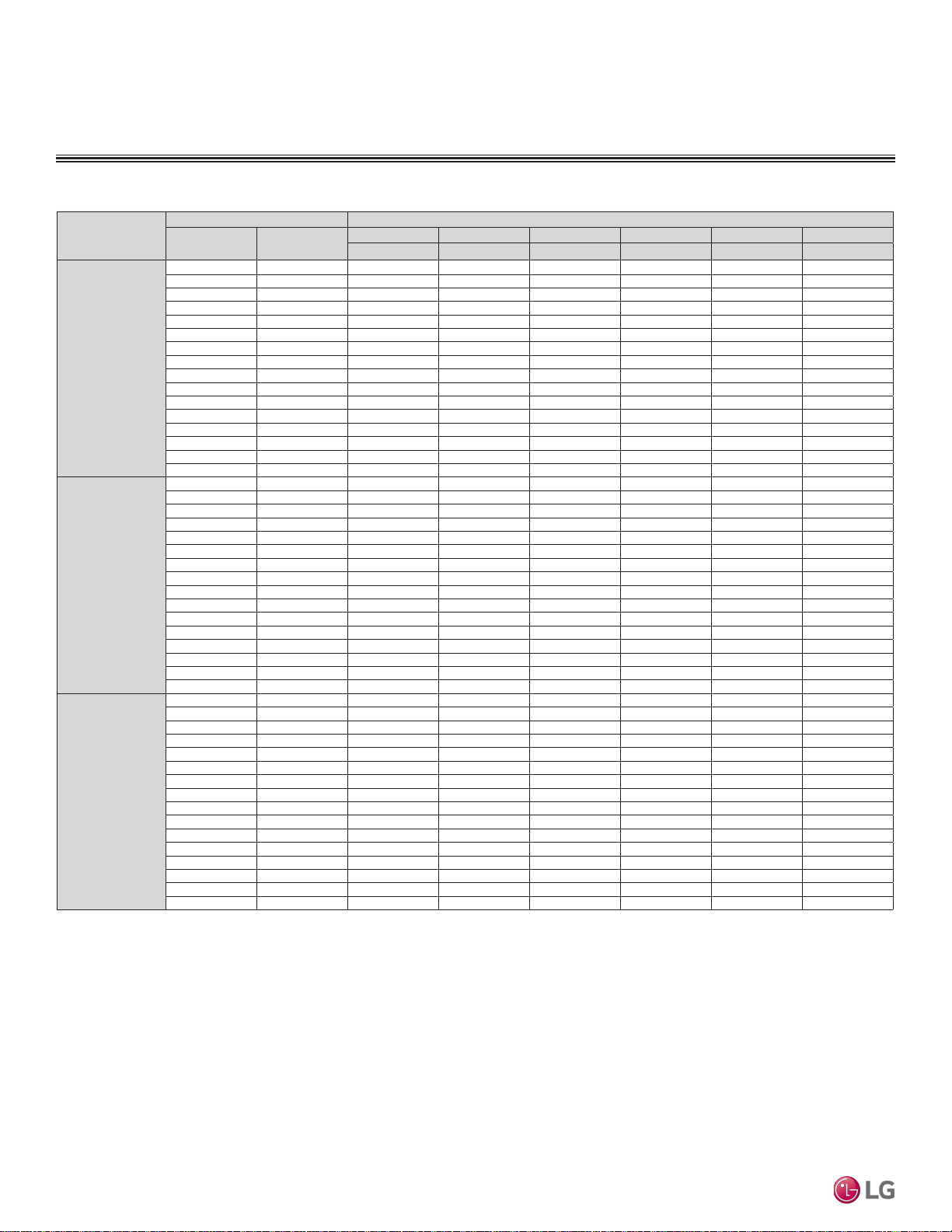
Due to our policy of continuous product innovation, some specications may change without notication.
©LG Electronics U.S.A., Inc., Englewood Cliffs, NJ. All rights reserved. “LG” is a registered trademark of LG Corp.
78 | STD. WALL-MOUNTED
Multi F and Multi F MAX Indoor Unit Engineering Manual
MULTI
F
MAX
MULTI
F
Table 37: Multi F Low Wall Console Indoor Units Heating Capacity Table.
Model No. /
Nominal Capacity of
Indoor Unit (Btu/h)
Outdoor Air Temp. Indoor Air Temp. °F DB
°F DB °F WB
61 64 68 70 72 75
TC TC TC TC TC TC
LQN090HV4
9,000
0 -0.4 5.40 5.33 5.28 5.25 5.17 4.95
5 4.5 6.09 6.01 5.96 5.93 5.86 5.63
10 9 6.77 6.70 6.64 6.62 6.54 6.32
17 15 7.68 7.61 7.56 7.53 7.46 7.21
20 19 8.03 7.95 7.90 7.88 7.80 7.53
25 23 8.60 8.52 8.47 8.45 8.37 8.07
30 28 9.09 9.02 8.97 8.94 8.86 8.60
35 32 9.59 9.51 9.46 9.43 9.36 9.13
40 36 10.03 9.95 9.90 9.88 9.80 9.57
45 41 10.47 10.40 10.35 10.32 10.25 10.02
47 43 10.65 10.58 10.53 10.50 10.42 10.20
50 46 10.82 10.75 10.70 10.67 10.60 10.34
55 51 11.11 11.03 10.98 10.96 10.88 10.58
60 56 11.11 11.03 10.98 10.96 10.88 10.62
63 59 11.11 11.03 10.98 10.96 10.88 10.65
68 64 11.11 11.03 10.98 10.96 10.88 10.70
LQN120HV4
12,000
0 -0.4 7.02 6.92 6.86 6.83 6.73 6.43
5 4.5 7.91 7.81 7.75 7.72 7.62 7.32
10 9 8.80 8.70 8.64 8.61 8.51 8.21
17 15 9.99 9.89 9.83 9.79 9.69 9.38
20 19 10.44 10.34 10.27 10.24 10.14 9.79
25 23 11.18 11.08 11.01 10.98 10.88 10.48
30 28 11.82 11.72 11.66 11.62 11.52 11.18
35 32 12.46 12.36 12.30 12.27 12.17 11.87
40 36 13.04 12.94 12.88 12.84 12.74 12.45
45 41 13.62 13.52 13.45 13.42 13.32 13.02
47 43 13.85 13.75 13.68 13.65 13.55 13.25
50 46 14.07 13.97 13.91 13.87 13.77 13.44
55 51 14.44 14.34 14.28 14.24 14.14 13.75
60 56 14.44 14.34 14.28 14.24 14.14 13.81
63 59 14.44 14.34 14.28 14.24 14.14 13.85
68 64 14.44 14.34 14.28 14.24 14.14 13.91
LMQN150HV
15,710
0 -0.4 8.78 8.66 8.58 8.54 8.41 8.04
5 4.5 9.90 9.77 9.69 9.65 9.52 9.15
10 9 11.01 10.89 10.80 10.76 10.64 10.27
17 15 12.49 12.37 12.29 12.25 12.12 11.73
20 19 13.05 12.93 12.84 12.80 12.68 12.25
25 23 13.98 13.85 13.77 13.73 13.61 13.11
30 28 14.78 14.66 14.58 14.53 14.41 13.98
35 32 15.59 15.46 15.38 15.34 15.21 14.84
40 36 16.31 16.18 16.10 16.06 15.94 15.57
45 41 17.03 16.91 16.82 16.78 16.66 16.29
47 43 17.32 17.19 17.11 17.07 16.95 16.58
50 46 17.60 17.47 17.39 17.35 17.22 16.81
55 51 18.06 17.94 17.85 17.81 17.69 17.19
60 56 18.06 17.94 17.85 17.81 17.69 17.27
63 59 18.06 17.94 17.85 17.81 17.69 17.32
68 64 18.06 17.94 17.85 17.81 17.69 17.39
Heating Capacity Table
LOW WALL CONSOLE INDOOR UNITS
TC = Total Capacity (kBtu/h).
Nominal capacity as rated 0 ft. above sea level and a 0 ft. level difference between outdoor and indoor units. Corresponding refrigerant piping length is accordance with low length of each outdoor unit. Nominal
heating capacity rating obtained with air entering the indoor unit at 70ºF dry bulb (DB) and 60ºF wet bulb (WB), and outdoor ambient conditions of 47ºF dry bulb (DB) and 43ºF wet bulb (WB).
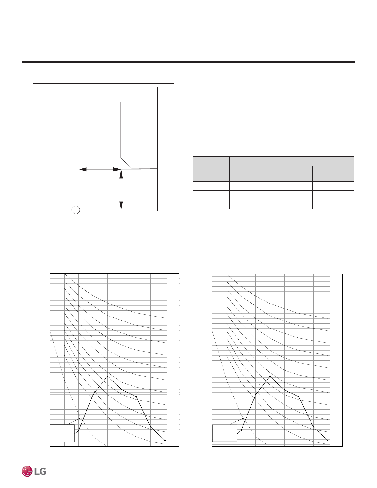
STD. WALL-MOUNTED | 79
Low Wall Console
Due to our policy of continuous product innovation, some specications may change without notication.
©LG Electronics U.S.A., Inc., Englewood Cliffs, NJ. All rights reserved. “LG” is a registered trademark of LG Corp.
MULTI
F
MAX
MULTI
F
Acoustic Data
LOW WALL CONSOLE INDOOR UNITS
• Measurement taken 2.6′ below the bottom of the unit and at a
distance of 3.3′ from face of unit.
• Measurements taken with no attenuation and units operating at full
load normal operating condition.
• Sound level will vary depending on a range of factors such as
construction (acoustic absorption coefficient) of particular area in
which the equipment is installed.
• Sound power levels are measured in dB(A).
• Tested in anechoic chamber per ISO Low 3745.
Model No.
Sound Pressure Levels (dB[A]) (Cooling and Heating)
High Fan Speed
Medium Fan
Speed
Low Fan Speed
LQN090HV4 38 32 27
LQN120HV4 39 32 27
LMQN150HV 44 39 35
Figure 97: Sound Pressure Level Measurement Location.
Table 38: Sound Pressure Levels (dB[A]).
2.6 ft.
3.3 ft.
Microphone
Figure 98:LQN090HV4 and LQN120HV4 Sound Pressure Level Diagrams.
LQN090HV4 LQN120HV4
10
15
20
25
30
35
40
45
50
55
60
65
70
75
80
63 125 250 500 1000 2000 4000 8000
Octave Band Sound Pressure Level (0dB = 20μPa )
Octave Band Center Frequency (Hz)
NC-15
NC-20
NC-25
NC-30
NC-35
NC-40
NC-45
NC-50
NC-55
NC-60
NC-65
Approximate
Hearing
Threshold
10
15
20
25
30
35
40
45
50
55
60
65
70
75
80
63 125 250 500 1000 2000 4000 8000
Octave Band Sound Pressure Level (0dB = 20μPa )
Octave Band Center Frequency (Hz)
NC-15
NC-20
NC-25
NC-30
NC-35
NC-40
NC-45
NC-50
NC-55
NC-60
NC-65
Approximate
Hearing
Threshold
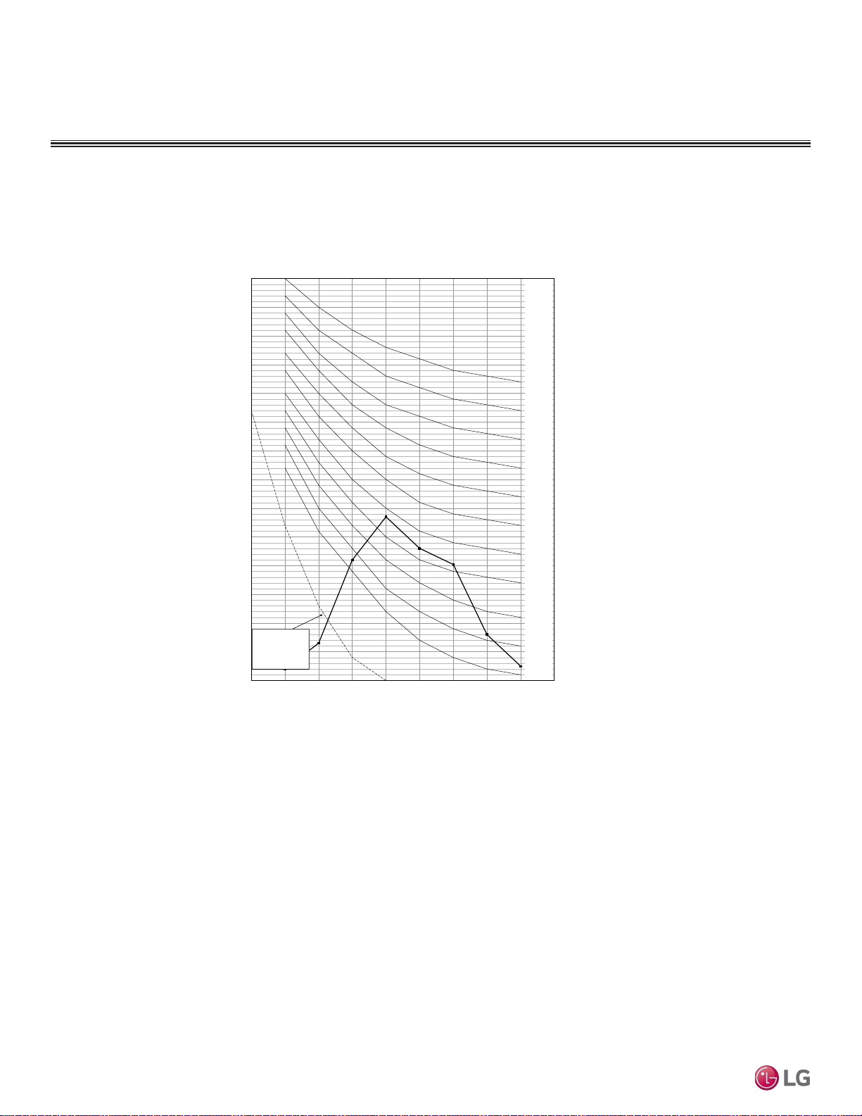
Due to our policy of continuous product innovation, some specications may change without notication.
©LG Electronics U.S.A., Inc., Englewood Cliffs, NJ. All rights reserved. “LG” is a registered trademark of LG Corp.
80 | STD. WALL-MOUNTED
Multi F and Multi F MAX Indoor Unit Engineering Manual
MULTI
F
MAX
MULTI
F
Acoustic Data
LOW WALL CONSOLE INDOOR UNITS
Figure 99:LMQN150HV Sound Pressure Level Diagram.
LMQN150HV
10
15
20
25
30
35
40
45
50
55
60
65
70
75
80
63 125 250 500 1000 2000 4000 8000
Octave Band Sound Pressure Level (0dB = 20μPa )
Octave Band Center Frequency (Hz)
NC-15
NC-20
NC-25
NC-30
NC-35
NC-40
NC-45
NC-50
NC-55
NC-60
NC-65
Approximate
Hearing
Threshold
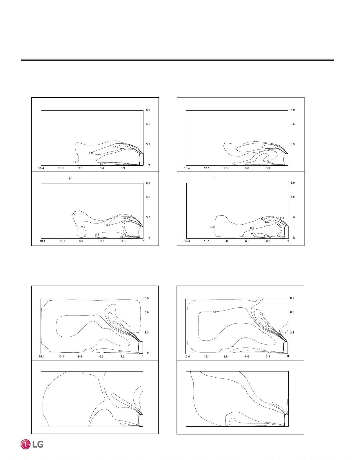
STD. WALL-MOUNTED | 81
Low Wall Console
Due to our policy of continuous product innovation, some specications may change without notication.
©LG Electronics U.S.A., Inc., Englewood Cliffs, NJ. All rights reserved. “LG” is a registered trademark of LG Corp.
MULTI
F
MAX
MULTI
F
Air Velocity and Temperature Distribution
LOW WALL CONSOLE INDOOR UNITS
Figure 100:LQN090HV4 and LQN120HV4 Air Velocity and Temperature Distribution Charts.
Figure 101:LMQN150HV Air Velocity and Temperature Distribution Charts.
Cooling
0 ft
0
0
0
Air velocity [ft/s]
Temperature [° ]
Discharge angle: 40°
Heating
0
0
9.8
6.6
6.6
3.3
3.3
0 ft
0 ft
1.6
1.6
Air velocity [ft/s]
Temperature [° ]
Discharge angle: 50°
Cooling
0
0
0 ft
3.3 6.6 9.8 13.1 16.4
0 ft
3.3
6.6
8.9
Air velocity [ft/s]
Temperature [°F]
1.6
1.6
1.6
4.9
3.3
6.6
6.6
8.2
62.6
73.4
66.2
60.8
64.4
64.4
62.6
66.2
73.4
Discharge angle: 40°
Heating
Discharge angle: 50°
0 ft
3.3 6.6 9.8 13.1 16.4
0 ft
3.3
6.6
8.9
0
0ft
Air velocity [ft/s]
Temperature [°F]
89.6
86.0
82.4
86.0
89.6
93.2
89.6
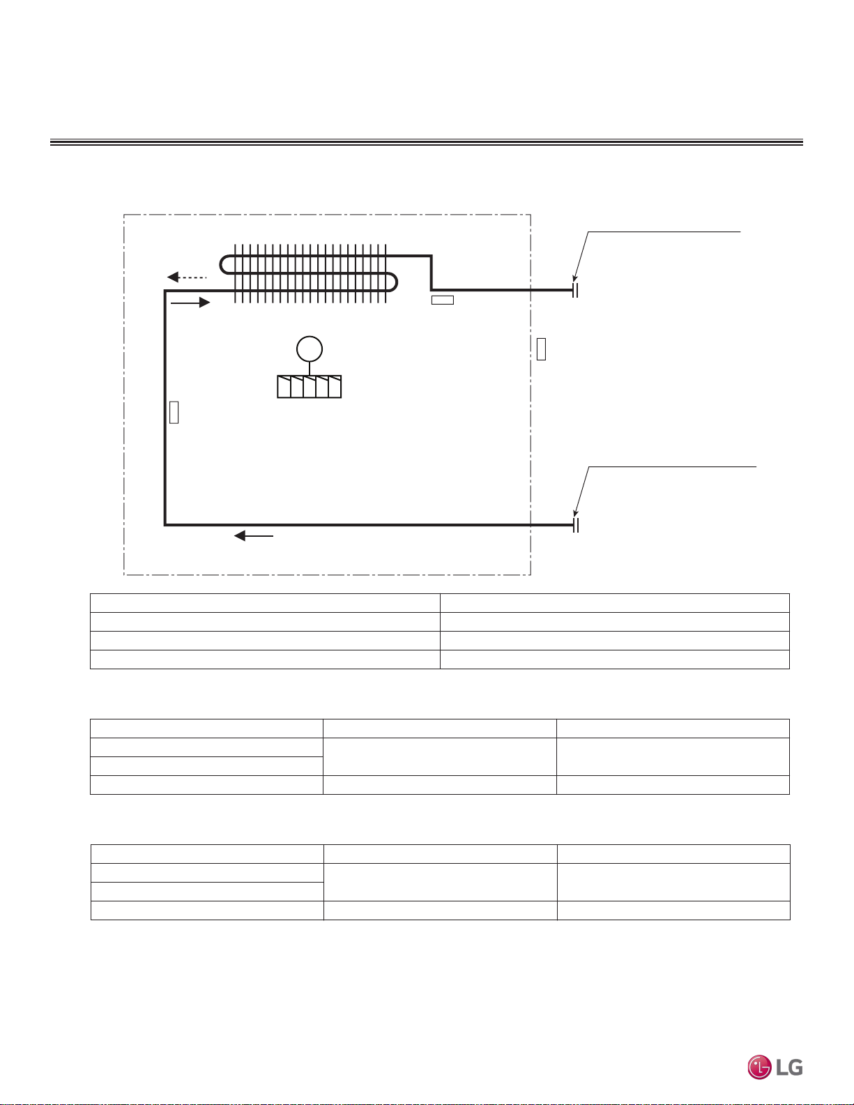
Due to our policy of continuous product innovation, some specications may change without notication.
©LG Electronics U.S.A., Inc., Englewood Cliffs, NJ. All rights reserved. “LG” is a registered trademark of LG Corp.
82 | STD. WALL-MOUNTED
Multi F and Multi F MAX Indoor Unit Engineering Manual
MULTI
F
MAX
MULTI
F
Refrigerant Flow Diagram
LOW WALL CONSOLE INDOOR UNITS
Figure 102:Multi F Low Wall Console Indoor Unit Refrigerant Flow Diagram.
Refrigerant pipe connection port diameters
Description PCB Connector
Thermistor for suction air temperature CN-ROOM
Thermistor for evaporator inlet temperature CN-PIPE / IN
Thermistor for evaporator outlet temperature CN-PIPE / OUT
Model
Ø
3/8 Ø1/4
Ø1/2 Ø1/4
Heat exchanger
Gas pipe connection port
(flare connection)
Liquid pipe connection port
(flare connection)
Cooling
Heating
Turbo fan
M
Thermistor for
suction air
temperature
Thermistor for
Evaporator
outlet temperature
Thermistor for
Evaporator inlet
temperature
LQN090HV4
LQN120HV4
LMQN150HV
Vapor (inch) Liquid (inch)
Refrigerant pipe connection pipe sizes
Model
Ø
3/8 Ø1/4
Ø1/2 Ø1/4
LQN090HV4
LQN120HV4
LMQN150HV
Vapor (inch) Liquid (inch)
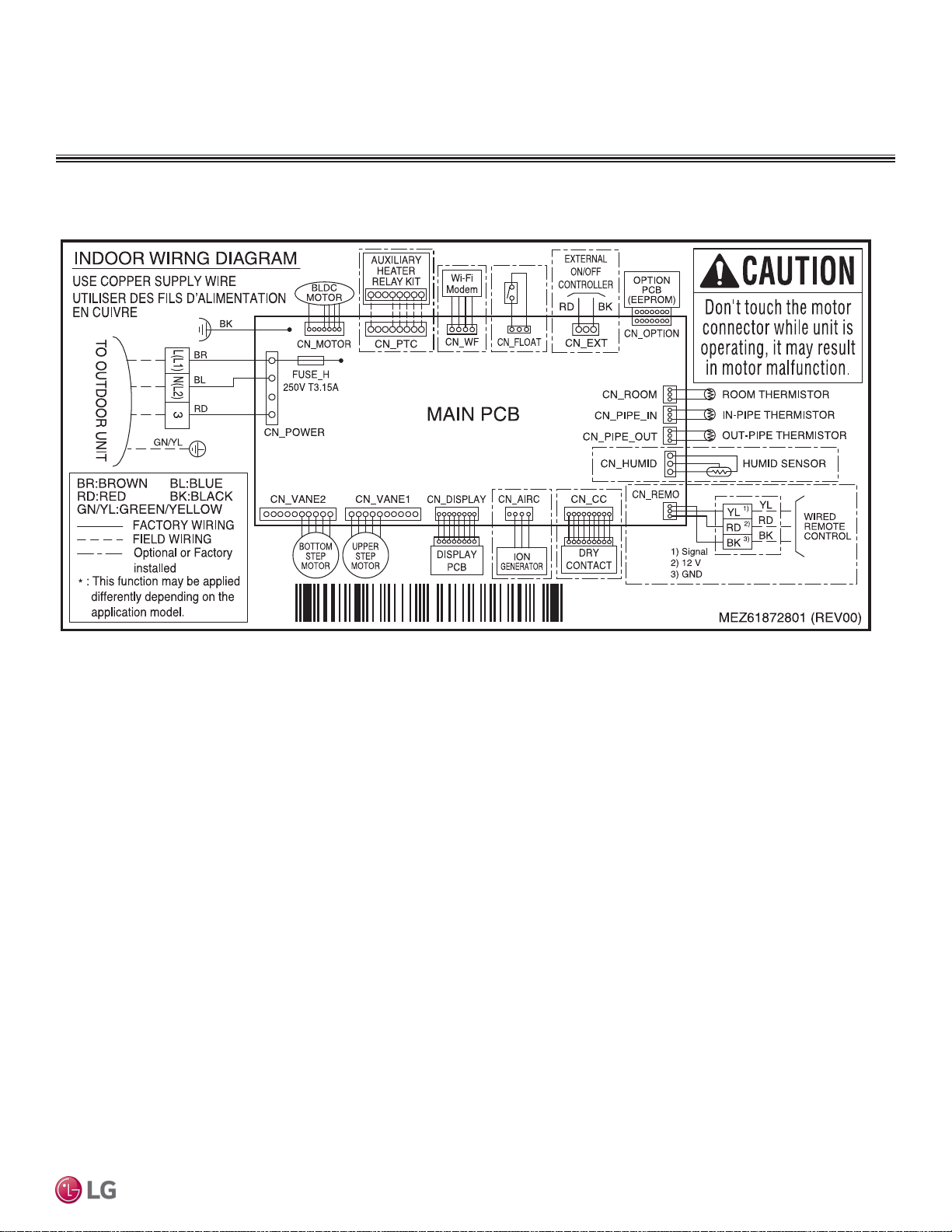
STD. WALL-MOUNTED | 83
Low Wall Console
Due to our policy of continuous product innovation, some specications may change without notication.
©LG Electronics U.S.A., Inc., Englewood Cliffs, NJ. All rights reserved. “LG” is a registered trademark of LG Corp.
MULTI
F
MAX
MULTI
F
Wiring Diagram
LOW WALL CONSOLE INDOOR UNITS
Figure 103:Multi F Low Wall Console LQN090HV4, LQN120HV4, and LMQN150HV Indoor Units Wiring Diagram.
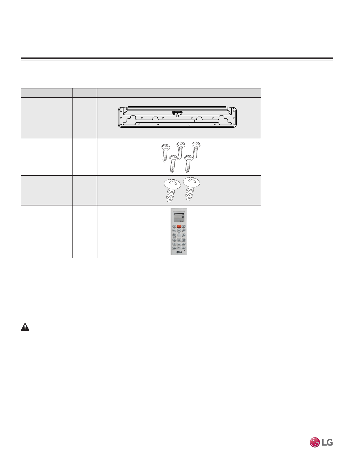
Due to our policy of continuous product innovation, some specications may change without notication.
©LG Electronics U.S.A., Inc., Englewood Cliffs, NJ. All rights reserved. “LG” is a registered trademark of LG Corp.
84 | STD. WALL-MOUNTED
Multi F and Multi F MAX Indoor Unit Engineering Manual
MULTI
F
MAX
MULTI
F
Factory Supplied Parts
Factory Supplied Materials
• Owner’s Manual
• Installation Manual
• Level
• Screwdriver
• Electric drill
• Hole core drill
• Flaring tool set
• Spanner (Half union)
• Thermometer
Factory Supplied Parts and Materials
Table 39: Parts Table.
Required Tools
LOW WALL CONSOLE INDOOR UNITS
Part Quantity Image
Installation Plate One (1)
Type “A” Screws Five (5)
Type “B” Screws
(M4 x 12L)
Two (2)
Wireless
Controller with Holder
AKB75735410
One (1)
WARNING
Installation work must be performed by trained personnel and in accordance with national wiring lows and all local or other applicable codes. Im-
proper installation can result in re, electric shock, physical injury, or death.
Note:
Read all instructions before installing this product. Become familiar with the unit’s components and connections, and the order of installation. Incorrect
installation can degrade or prevent proper operation.
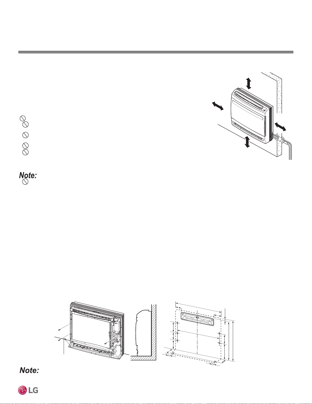
STD. WALL-MOUNTED | 85
Low Wall Console
Due to our policy of continuous product innovation, some specications may change without notication.
©LG Electronics U.S.A., Inc., Englewood Cliffs, NJ. All rights reserved. “LG” is a registered trademark of LG Corp.
MULTI
F
MAX
MULTI
F
Selecting the Best Location
Do’s
• Place the unit where air circulation will not be blocked.
• Place the unit where drainage can be obtained easily.
• Place the unit where noise prevention is taken into consideration.
• Ensure there is sufficient space from the ceiling and floor.
• Ensure there is sufficient maintenance space.
• Locate the indoor unit where it can be easily connected to the outdoor unit or branch
distribution unit.
Don’ts
• Do not install the unit near a heat or steam source, or where considerable amounts of oil,
iron powder, or flour are used.
• Do not install the unit where sulfuric acid and flammable or corrosive gases are generated,
vented into, or stored.
• Do not install the unit near high-frequency generators.
• Do not install the unit near a doorway.
The unit will be damaged, will malfunction, and / or will not operate as designed if
installed in any of the conditions listed.
Installation and Best Layout Practices
Selecting Installation Method
The unit can be installed in one of three configurations:
• On the floor.
• Mounted on the wall above floor molding.
• Half concealed (recessed) in an opening in the wall.
Figure 105:Floor Installation
If the unit is installed near a body of water, certain components are at risk of being corroded. Appropriate anti-corrosion methods must be taken for the
unit and all components.
LOW WALL CONSOLE INDOOR UNITS
Installing in an Area Exposed to Unconditioned Air
In some installation applications, areas (floors, walls) in some rooms will be exposed to unconditioned air (room will be above or next to an
unheated garage or storeroom). To countermeasure:
• Verify that carpet is or will be installed (carpet will increase the temperature by three degrees).
• Add insulation between the floor joists.
• Install radiant heat or another type of heating system to the floor.
• Indoor units (IDUs) must not be placed in an environment where the IDUs will be exposed to harmful volatile organic compounds (VOCs)
or in environments where there is improper air make up or supply or inadequate ventilation. If there are concerns about VOCs in the envi-
ronment where the IDUs are installed, proper air make up or supply and/or adequate ventilation must be provided. Additionally, in buildings
where IDUs will be exposed to VOCs, consider a third party factory-applied epoxy coating to the fan coils for each IDU where the entire coil
is dipped, not sprayed.
• If the unit is installed near a body of water, the installation parts are at risk of corroding. Appropriate anti-corrosion methods must be taken for
the unit and all installation parts.
9-27/32 (250) or below
from the Floor
More than
11-13/16 (300)
[Unit : inch (mm)]
More than
11-13/16 (300)
More than
11-13/16 (300)
6 screw (M*25L)
2-17/32 (64)
6-1/4 (159)
27-9/16 (700)
[Unit : inch (mm)]
1-1/32 (26)
25-15/32 (647)
7-3/32
(180)
5-1/2(140)
23-5/8 (600)
22-19/32 (574)
6-11/16 (170)
6-11/16
(170)
1-3/16 (30.5)
1-3/16 (30.5)
5-1/2
(140)
6-5/16 (160)
8-9/32 (210)
Figure 104:Minimum Clearance Requirements.
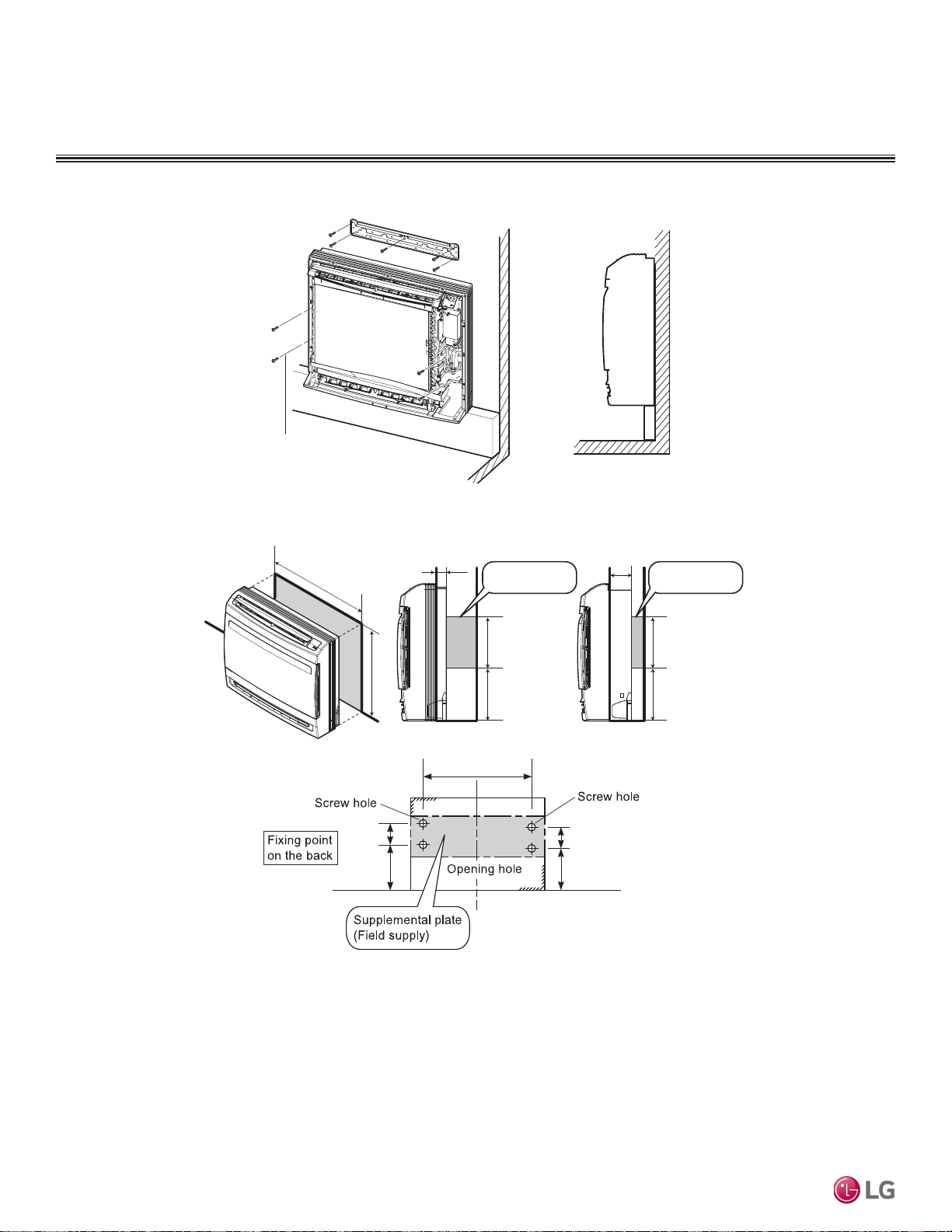
Due to our policy of continuous product innovation, some specications may change without notication.
©LG Electronics U.S.A., Inc., Englewood Cliffs, NJ. All rights reserved. “LG” is a registered trademark of LG Corp.
86 | STD. WALL-MOUNTED
Multi F and Multi F MAX Indoor Unit Engineering Manual
MULTI
F
MAX
MULTI
F
Mounting the Installation Plate
The mounting wall must be strong and solid enough to protect the unit from vibration.
• Mount the installation plate on the wall using the Type “A” screws. If mounting the unit on concrete, consider using anchor bolts.
• Always mount the installation plate horizontally. Measure the wall and mark the centerline using thread and a level.
Figure 106:Wall Installation.
Figure 107:Recessed Installation.
Installation Plate
Molding
4 screw (M*25L)
26-3/8 (670)
1-25/32 (45)
23-1/32 (585)
7/8 (200)
5-29/32 (150)
7/8 (200)
5-29/32 (150)
Wall
Hole
Supplemental plate
(Field supply)
3-3/4 (95)
Supplemental plate
(Field supply)
25-15/32 (647)
6-11/16 (170)
5-1/2 (140)
6-11/16 (170)
5-1/2 (140)
[Unit : inch (mm)]
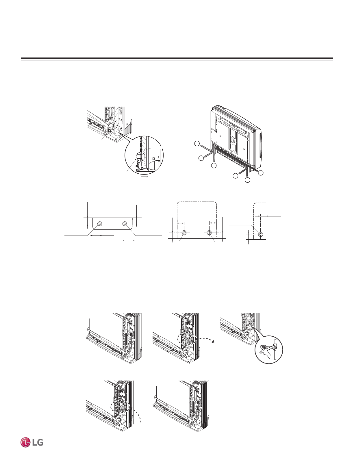
STD. WALL-MOUNTED | 87
Low Wall Console
Due to our policy of continuous product innovation, some specications may change without notication.
©LG Electronics U.S.A., Inc., Englewood Cliffs, NJ. All rights reserved. “LG” is a registered trademark of LG Corp.
MULTI
F
MAX
MULTI
F
Selecting Pipe Routing
The pipe can be routed in one of six directions as shown in Figure 108.
Figure 108:Pipe Holes and Routing.
3
1
2
6
5
4
Pipe Guide
Pipe Guide
Connecting Pipe must be placed
inside to the pipe guide.
Connecting
Pipe
Connecting
Pipe
[Unit : inch (mm)]
1-25/32 (45)
3-17/32 (90)
2-15/16 (75)
Left bottom piping
Right bottom piping
Left/right piping
Right back piping
2-3/8 (60)
1-9/16 (40)
1-31/32 (50)
Wall
3-17/32 (90)
2-15/16 (75)
Left back piping
Right back piping
1-25/32 (45)
1-25/32 (45)
Pipe Connection
Connect the pipes as shown in Figure 109
1. Hold up the Sensor Link.
2. Separate the Pipe Bracket (2 screws)
3. Connect the refrigerant pipe. (Refer to next page)
4. Assemble the Pipe Bracket (2 screws)
5. Put down the Sensor Link.
Figure 109:Pipe Connection.
21
54
3
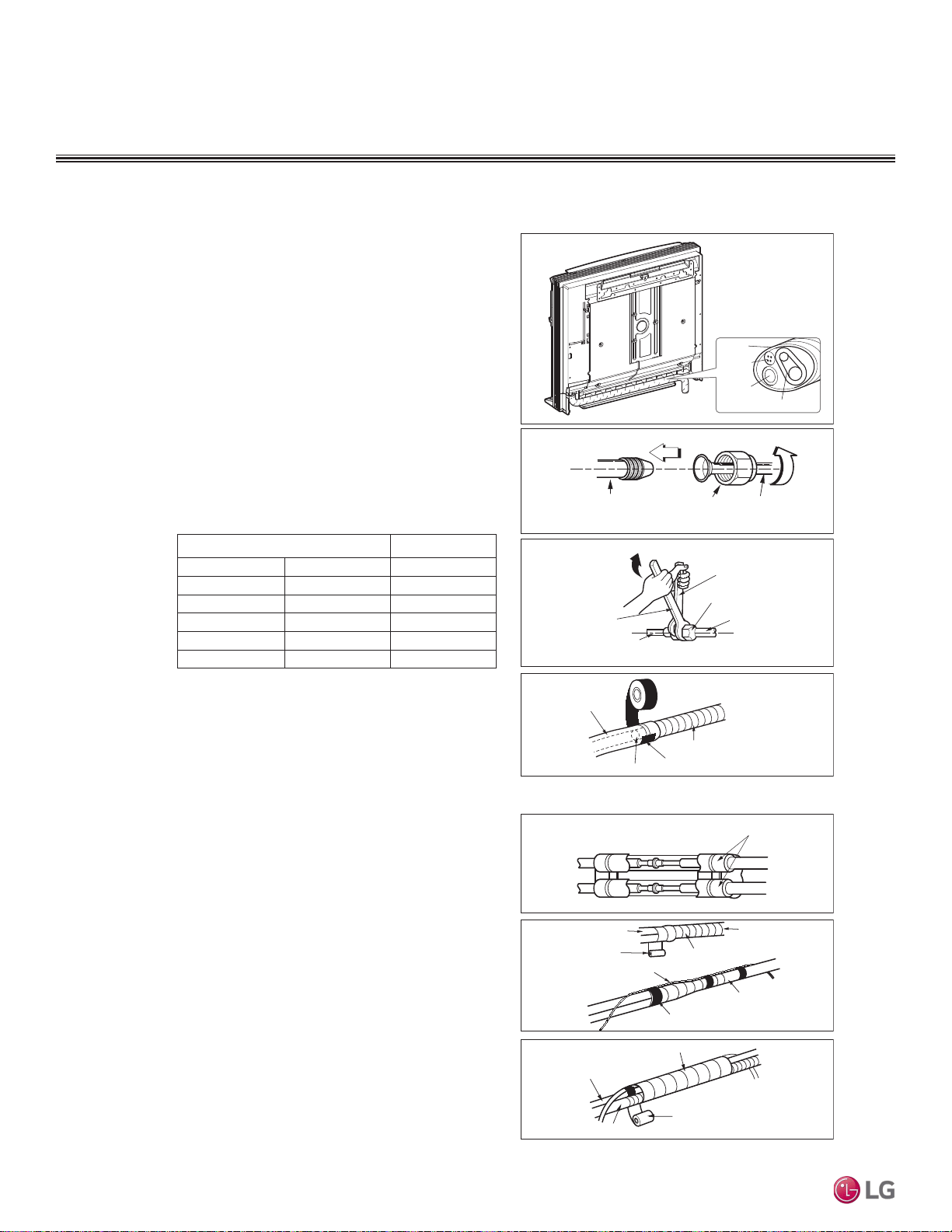
Due to our policy of continuous product innovation, some specications may change without notication.
©LG Electronics U.S.A., Inc., Englewood Cliffs, NJ. All rights reserved. “LG” is a registered trademark of LG Corp.
88 | STD. WALL-MOUNTED
Multi F and Multi F MAX Indoor Unit Engineering Manual
MULTI
F
MAX
MULTI
F
Installation and Best Layout Practices
LOW WALL CONSOLE INDOOR UNITS
Pipe Routing and Insulation
Connecting the installation pipe and
drain hose to the indoor unit.
1. Align the center of the pipes and sufficiently
tighten the flare nut by hand.
2. Tighten the flare nut with a wrench.
3. When needed to extend the drain hose of
indoor unit, assemble the drain pipe as
shown on the drawing
Wrap the insulation material around
the connecting portion.
1. Overlap the connection pipe insulation
material and the indoor unit pipe insulation
material. Bind them together with vinyl tape
so that there may be no gap.
2. Wrap the area which accommodates the rear
piping housing section with vinyl tape.
3. Bundle the piping and drain hose together by
wrapping them with vinyl tape sufficient
enough to cover where they fit into the rear
piping housing section.
If the drain hose is routed inside the room
insulate the hose with an insulation material*
so that dripping from sweating (condensation)
will not damage furniture or floors.
* Foamed polyethylene or equivalent is
recommended.
mm inch kgf
.
m
Ø6.35 1/4 1.8~2.5
Ø9.52 3/8 3.4~4.2
Ø12.7 1/2 5.5~6.5
Ø15.88 5/8 6.3~8.2
Ø19.05 3/4 9.9~12.1
Outside diameter Torque
Insulation material
Vinyl tape(narrow)
Connection pipe
Connecting cable
Vinyl tape (wide)
Wrap with vinyl tape
Indoor unit pipe
Pipe
Wrap with vinyl tape
Drain hose
Pipe
Vinyl tape(wide)
Indoor unit tubing Flare nut Pipes
Wrench
Indoor unit tubing
Open-end wrench (fixed)
Connection pipe
Flare nut
Vinyl tape(narrow)
Adhesive
Drain pipe
Indoor unit drain hose
Connecting pipe
Connecting
cable
Tape
Drain hose
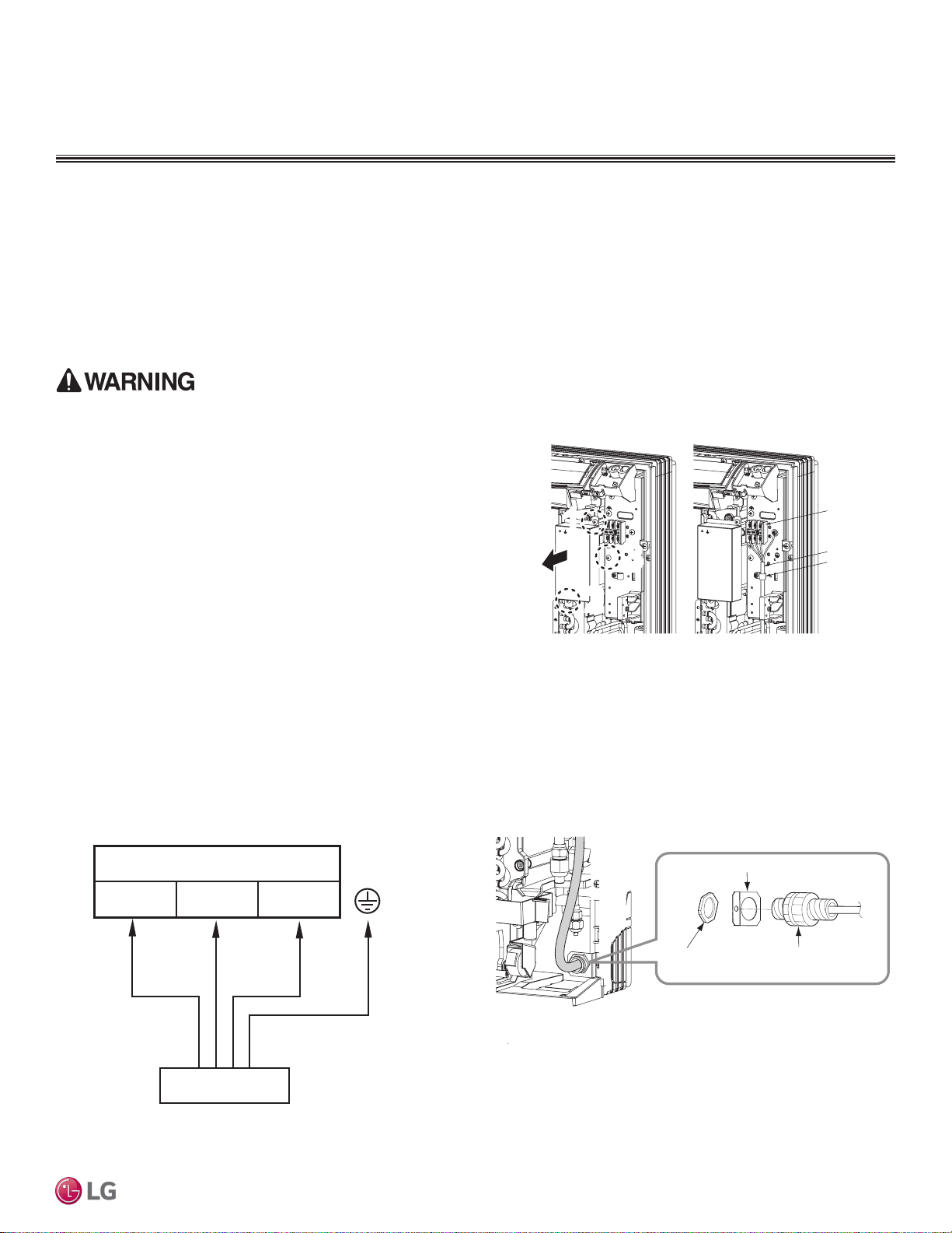
STD. WALL-MOUNTED | 89
Low Wall Console
Due to our policy of continuous product innovation, some specications may change without notication.
©LG Electronics U.S.A., Inc., Englewood Cliffs, NJ. All rights reserved. “LG” is a registered trademark of LG Corp.
MULTI
F
MAX
MULTI
F
Installation and Best Layout Practices
Power Wiring / Communications Cable Guidelines
LOW WALL CONSOLE INDOOR UNITS
• Follow manufacturer’s circuit diagrams in the technical manuals.
• Confirm power source specifications.
• Confirm that the electrical capacity is sufficient.
• Starting current must be maintained ±10 percent of the rated current marked on the outdoor unit name plate.
• Confirm cable thickness specifications.
• It is required that a circuit breaker is installed, especially if conditions could become wet or moist.
• Include a disconnect in the power wiring system, add an air gap contact separation of at least 1/8 inch in each active (phase) conductor.
Figure 110: Connecting Power Wiring / Communications Cable.
Connect Power Wiring and
Communications Cable
1. Insert the power wiring / communications cable from the outdoor
unit or branch distribution unit (Multi F MAX systems only).
2. Remove screws 1 and 2 and remove control box cover.
3. Connect each wire to its appropriate terminal on the indoor unit
control board. Verify that the color and terminal numbers from the
outdoor unit or branch distribution unit (Multi F MAX systems only)
wiring match the color and terminal numbers on the indoor unit.
4. Secure power wiring/communications cable with cable restraint.
Figure 111:Simplied View of Indoor Unit to Outdoor Unit / Branch
Distribution Unit Terminal Connections
Figure 112:Securing Wiring to Unit.
• Loose wiring will cause unit to malfunction, overheat, and catch
fire, resulting in severe injury or death.
Note:
• Terminal screws will become loose during transport. Properly
tighten the terminal connections during installation.
A voltage drop will cause the following problems:
• Magnetic switch vibration, fuse breaks, or disturbance to the
normal function of an overload protection device.
• Compressor will not receive the proper starting current.
11
3
3
2
2
Terminal Block
Connecting Cable
Clamp Cord
Bracket
Conduit
(Field supply)
Lock nut
(Field supply)
L(L1) N(L2) 3
Terminal Block of Indoor Unit
Outdoor
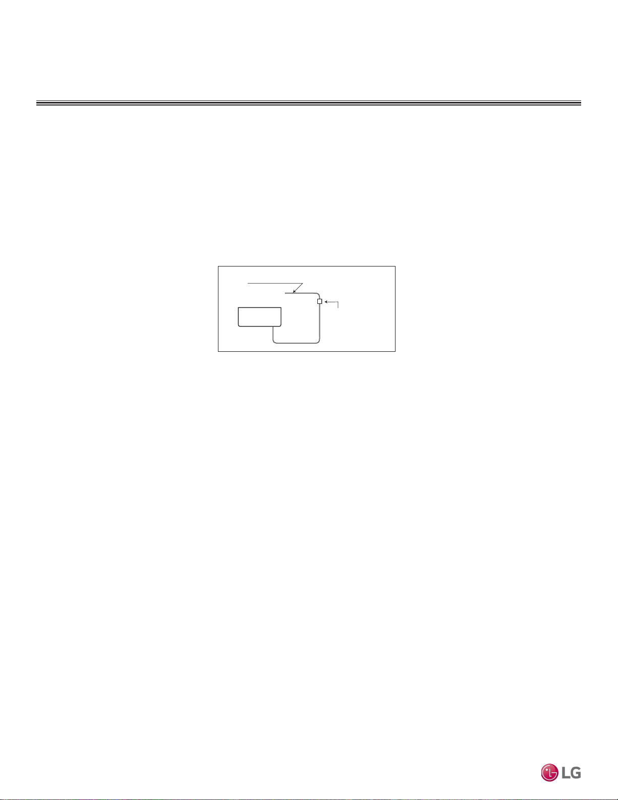
Due to our policy of continuous product innovation, some specications may change without notication.
©LG Electronics U.S.A., Inc., Englewood Cliffs, NJ. All rights reserved. “LG” is a registered trademark of LG Corp.
90 | STD. WALL-MOUNTED
Multi F and Multi F MAX Indoor Unit Engineering Manual
MULTI
F
MAX
MULTI
F
LOW WALL CONSOLE INDOOR UNITS
Installation and Best Layout Practices
Power Connection
1. All wiring must comply with applicable code.
2. Select a power source that is capable of supplying the current required by the air conditioner.
3. Feed the power source to the unit via a distribution switch board designed for this purpose.
4. The terminal screws inside the control box may be loose due to vibration during transport. Check the screws for loose connection.
(Running the air conditioner with loose connection can overload and damage electrical components.)
5. Always ground the air conditioner with a grounding wire and connector to meet applicable code.
Figure 113:Power Wiring.
Air
Conditioner
Main power source
Circuit Breaker
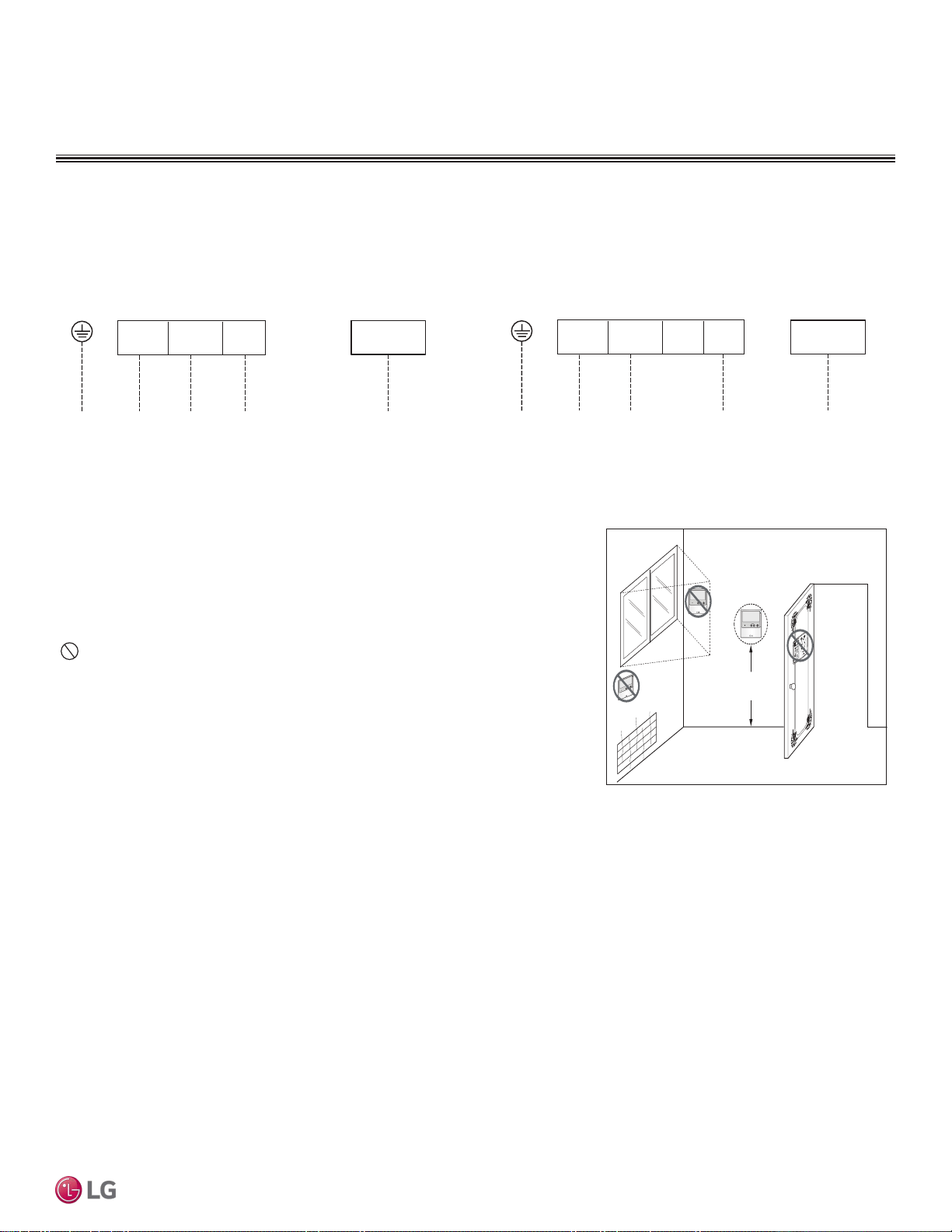
STD. WALL-MOUNTED | 91
Low Wall Console
Due to our policy of continuous product innovation, some specications may change without notication.
©LG Electronics U.S.A., Inc., Englewood Cliffs, NJ. All rights reserved. “LG” is a registered trademark of LG Corp.
MULTI
F
MAX
MULTI
F
4 to 5 feet
above the floor
NO
NO
NO
YES
Remote Controller
TEMP
Remote Controller
TEMP
Re
m
ote C
o
nt
roller
TEMP
Installation and Best Layout Practices
LOW WALL CONSOLE INDOOR UNITS
Wired Controller Connections
Figure 114:Wired Controller Connection on Indoor Unit Terminal Block— . Figure 115:Wired Controller Connection on Indoor Unit Terminal Block—
Figure 116:Proper Location for the Wired Controller.
Wired controllers include a sensor to detect room temperature. To maintain comfort
levels in the conditioned space, the wired controller must be installed in a location away
from direct sunlight, high humidity, and where it could be directly exposed to cold air.
Controller must be installed four (4) to five (5) feet above the floor where its LED display
can be read easily, in an area with good air circulation, and where it can detect an aver-
age room temperature.
Do not install the wired controller near or in:
• Drafts or dead spots behind doors and in corners
• Hot or cold air from ducts
• Radiant heat from the sun or appliances
• Concealed pipes and chimneys
• An area where temperatures are uncontrolled, such as an outside wall
Wired Controller Placement
Indoor Unit Terminal Block
L (L1
)N (L2)
GND
GRN / YLW
BR
BL
RD
CN-REMO
To Outdoor Unit or Branch Distribution Unit
(Multi F MAX Systems Only)
To Wired Controller
3
Indoor Unit Terminal Block
L (L1) N (L2)
GND
GRN / YLW
BR
BL
RD
CN-REMO
To Outdoor Unit or Branch Distribution Unit
(Multi F MAX Systems Only)
To Wired Controller
3
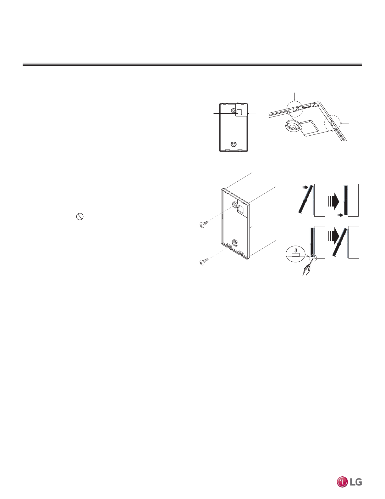
Due to our policy of continuous product innovation, some specications may change without notication.
©LG Electronics U.S.A., Inc., Englewood Cliffs, NJ. All rights reserved. “LG” is a registered trademark of LG Corp.
92 | STD. WALL-MOUNTED
Multi F and Multi F MAX Indoor Unit Engineering Manual
MULTI
F
MAX
MULTI
F
Hanging the Wired Controller
1. The controller wiring / cable can be installed in one of three direc-
tions: top, back, or on the right side. If top or right side installation
is desired, remove cable guide grooves on the controller, and
then position wiring / cable on applicable side.
2. Choose and mark the area of installation. Use the provided parts
and screw the wall plate into place. Install the controller wall plate
to fit the electrical box if one is present. Ensure that no gaps exist
between the wall plate and the wall itself.
3. Arrange wiring / cables so as not to interfere with the controller
circuitry. Position the wired controller on the wall plate. Snap into
place by pressing the bottom part of the wired controller onto
the wall plate. Make sure that no gaps exist between the wired
controller and the wall plate on all sides.
4. To remove wired controller from the wall plate, insert a screw-
driver into the two holes at the bottom. Twist screwdriver to
release controller. Do not damage the controller components
when removing.
Back
Top
Top
Right
Side
Right
Side
Wall Wall
Wall Wall
Installing the Controller
Removing the Controller
Figure 117:Removing the Cable Guide Grooves.
Figure 118:Attaching the Wall Plate.
Figure 119:Installing / Removing
the Controller.
LOW WALL CONSOLE INDOOR UNITS
Installation and Best Layout Practices
Assigning the Thermistor for Temperature Detection
Each indoor unit includes a return air thermistor assigned to sense the temperature. If a wired controller is installed, there is a choice of
sensing temperature with either the indoor unit return air thermistor or the thermistor in the wired controller. It is also an option to set both
thermistors to sense temperature so that indoor unit bases its operation on the first thermistor to reach the designated temperature differen-
tial. For applicable indoor units, an optional Remote Temperature Sensor can be used in lieu of the return air thermistor—either alone or in
conjunction with a wired controller thermistor as previously described.

CEILING-CONCEALED
DUCT (LOW STATIC)
INDOOR UNIT DATA
“Mechanical Specifications” on page 94
“General Data / Specifications” on page 95
“Dimensions” on page 96
“Cooling Capacity Table” on page 97
“Heating Capacity Table” on page 99
“External Static Pressure” on page 100
“Acoustic Data” on page 101
“Refrigerant Flow Diagrams” on page 102
“Wiring Diagram” on page 104
“Factory Supplied Parts and Materials” on page 106
“Installation and Best Layout Practices” on page 107
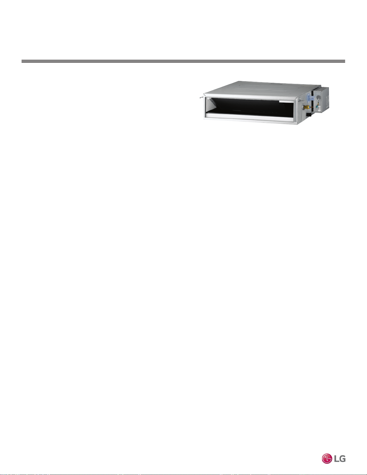
Mechanical Specications and Features
DUCT (LOW STATIC) INDOOR UNITS
Ceiling-Concealed Duct (Low Static)
Indoor Unit
General
All LG indoor units are factory assembled, wired, piped, and pro-
vided with a control circuit board, fan, and motor. Ceiling-Concealed
Duct (Low Static) units have a sound rating no higher than 36 dB(A)
as tested per KSA0701 ISO Standard 3745, and are designed for
low-static pressure up to 0.20″WG.
Coil
Indoor unit coils are factory built and are comprised of aluminum fins
mechanically bonded to copper tubing. Each unit has two rows of
coils, which are pressure tested at the factory. Each unit is provided
with a factory installed condensate drain pan below the coil.
Refrigerant System
System is designed for use with R410A refrigerant. The refrigeration
circuit is pressure-tested at the factory and shipped with a holding
charge of helium gas. Refrigerant pipe connections are 45° flare,
and all refrigerant lines from the outdoor unit to the indoor units must
be field insulated.
Electrical
Each indoor unit is designed to operate using 208–230/60/1 power
with voltage variances of ±10%.
Casing
The case has a low profile design with a maximum height of 7.5
inches designed to mount fully concealed above a finished ceiling in
as little as 8 inches vertical space. Casing is manufactured of gal-
vanized steel plate, and provided with hanger brackets designed to
support the weight on four corners. Unit has a front horizontal supply
air discharge outlet, and one rear horizontal return air inlet; unit is
also field-convertible for a rear bottom return.
Fan Assembly and Control
The units have at least two direct-drive, Sirocco fans made of
high strength ABS HT-700 polymeric resin that are statically and
dynamically balanced. The fans are mounted on a common brush-
less digitally controlled (BLDC) motor with permanently lubricated
and sealed ball bearings. The fan / motor assembly is mounted on
vibration-attenuating rubber grommets. Fan speed is controlled using
a microprocessor-based direct digital control algorithm. The indoor
fan has Low, Med, High, and Auto settings for Cooling mode; and
has Low, Med, High, and Auto settings for Heating mode. Each of the
settings can be field-adjusted from the factory setting (RPM / ESP).
The Auto setting adjusts the fan speed based on the difference
between the controller set-point and space temperature.
Air Filter
Return air is filtered with a factory-supplied, removable, washable
filter accessible from the rear of the indoor unit.
Microprocessor Control
The unit is provided with an integrated control panel to communicate
with the outdoor unit. All unit operation parameters are stored in non-
volatile memory residing on the unit microprocessor. The micropro-
cessor controls space temperature through using the value provided
by the temperature sensor within the indoor unit. The microprocessor
control will activate indoor unit operation when the indoor room tem-
perature falls below or rises above a setpoint temperature, at which
point, a signal is sent to the outdoor unit to begin the appropriate
mode. The microprocessor will also provide self-diagnostics and auto
restart functions. A field-supplied four-wire power / communications
cable must be installed to connect the indoor unit(s) to the outdoor
unit.
The indoor units are Wi-Fi compatible with the addition of an LG Wi-
Fi module accessory, and can be controlled by LG’s Smart ThinQ™
app on a smart device. A field-supplied Wi-Fi network and smart
device are required. The Smart ThinQ app is free, and is available
for Android™ and iOS. (Android is a trademark of Google LLC.)
Controls
The indoor unit controller of choice must be ordered separately.
Communication between the indoor units and the outdoor unit is
accomplished through 14 AWG, four-core, stranded, shielded or
unshielded power / communication cable.
Condensate Lift/Pump
The indoor unit is provided with a factory installed and wired conden-
sate lift/pump capable of providing a minimum 27.5 inch lift from the
bottom surface of the unit. Drain pump has a safety switch to shut off
the indoor unit if the condensate rises too high in the drain pan.
• Inverter (Variable speed fan)
• External mounted drain pump
• Control lock function
• Auto operation
• Auto restart operation
• Dehumidification function
• Two thermistor control
• External static pressure control
• Self-diagnostics function
• Group control
• Wired controller ordered separately
• Wi-Fi compatible
Features
Figure 120: Ceiling-Concealed Duct (Low Static) Indoor Unit.
Due to our policy of continuous product innovation, some specications may change without notication.
©LG Electronics U.S.A., Inc., Englewood Cliffs, NJ. All rights reserved. “LG” is a registered trademark of LG Corp.
94 | DUCT (LOW STATIC)
Multi F and Multi F MAX Indoor Unit Engineering Manual
MULTI
F
MAX
MULTI
F
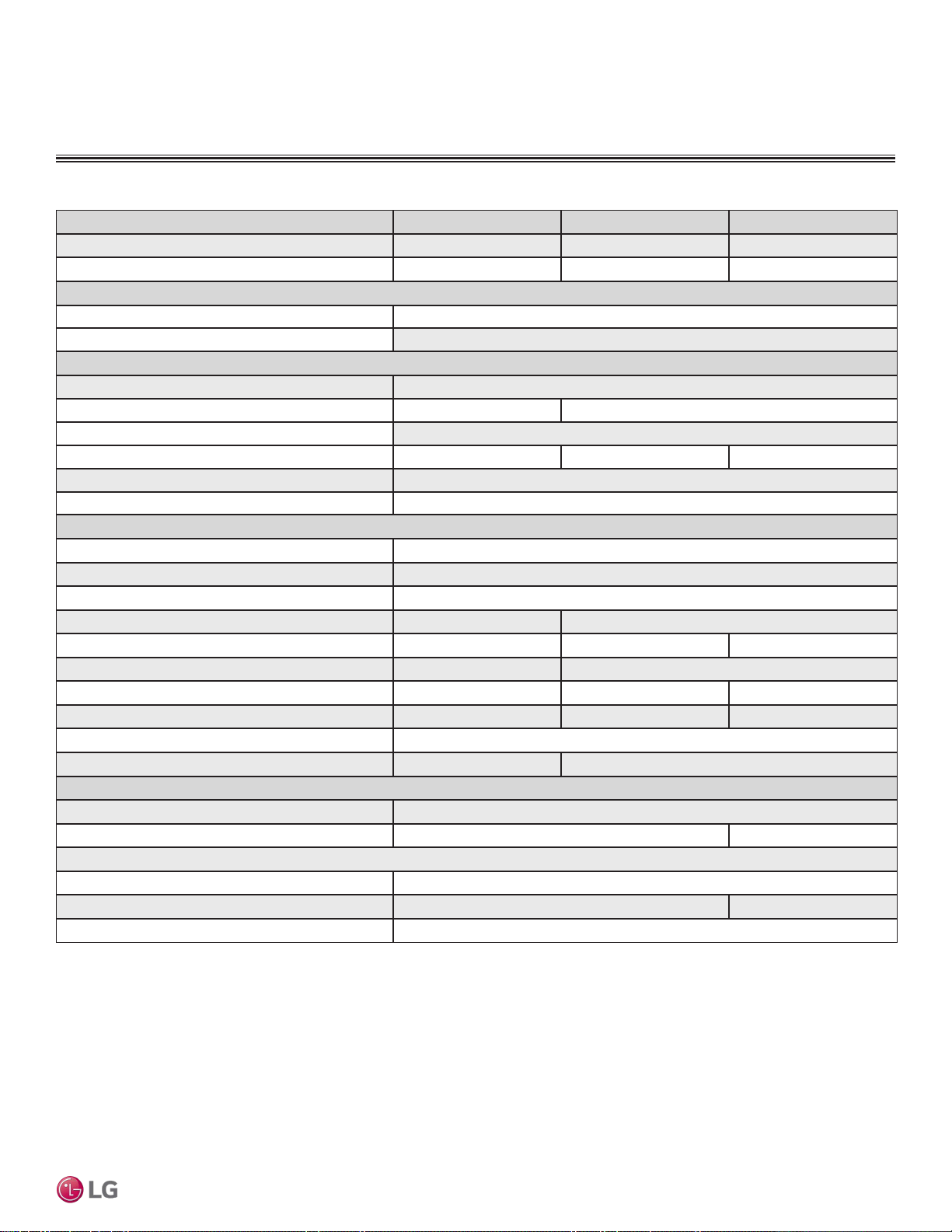
Model Name LDN097HV4 LDN127HV4 LDN187HV4
Nominal Cooling Capacity (Btu/h)
1
9,000 12,000 18,000
Nominal Heating Capacity (Btu/h)
1
10,400 13,800 20,800
Operating Range
Cooling (°F WB)
57-77
Heating (°F DB)
59-81
Fan
Type
Sirocco
Motor Output (W) x Qty.
19 x 1 5 x 1, 19 x 1
Motor/Drive
Brushless Digitally Controlled / Direct
Airflow Rate CFM (H/M/L)
318 / 247 / 194 353 / 300 / 247 530 / 441 / 353
Factory Set External Static Pressure (in. wg)
0.10
Max. External Static Pressure (in. wg)
0.20
Unit Data
Refrigerant Type
2
R410A
Refrigerant Control
EEV
Power Supply V, Ø, Hz
3
208-230, 1, 60
Rated Amps (A)
0.40 0.80
Sound Pressure Level dB(A) (H/M/L)
4
30 / 26 / 23 31 / 28 / 27 36 / 34 / 31
Dimensions (W x H x D, in.)
27-9/16 x 7-15/32 x 27-9/16 35-7/16 x 7-15/32 x 27-9/16
Net Unit Weight (lbs.)
39 51 48.5
Shipping Weight (lbs.)
46 60 57.3
Power Wiring / Communications Cable (No. x AWG)
5
4 x 14
Heat Exchanger (Row x Column x Fin / inch) x Number
(2 x 11 x 14) x 1 (2 x 11 x 18) x 1
Pipe Size
Liquid Line (in.)
1/4
Vapor Line (in.)
3/8 1/2
Connection Size
Liquid Line (in.)
1/4
Vapor Line (in.)
3/8 1/2
Drain O.D. / I.D. (in.)
1-1/4, 1
1
Nominal capacity is rated 0 ft. above sea level with corresponding refrigerant piping length in
accordance with standard length of each outdoor unit and a 0 ft. level difference between outdoor and
indoor units. All capacities are net with a combination ratio between 95 – 105%.
Nominal cooling capacity rating obtained with air entering the indoor unit at 80ºF dry bulb (DB) and 67ºF
wet bulb (WB) and outdoor ambient conditions of 95ºF dry bulb (DB) and 75ºF wet bulb (WB).
Nominal heating capacity rating obtained with air entering the indoor unit at 70ºF dry bulb (DB) and 60ºF
wet bulb (WB) and outdoor ambient conditions of 47ºF dry bulb (DB) and 43ºF wet bulb (WB).
2
This unit comes with a dry helium charge.
3
Acceptable operating voltage: 187V-253V.
4
Sound pressure levels are tested in an anechoic chamber under ISO Standard 3745 and are the
same in both cooling and heating mode. These values can increase due to ambient conditions during
operation.
5
All power wiring / communications cable to the IDUs be minimum 14 AWG, 4-conductor, stranded,
shielded or unshielded (if shielded, must be grounded to chassis at ODU only) and must comply with
applicable local and national codes.
DUCT (LOW STATIC) INDOOR UNITS
General Data / Specications
Table 40: Multi F Ceiling-Concealed Low-Static Ducted Indoor Unit General Data.
DUCT (LOW STATIC) | 95
Ceiling-Concealed Duct (Low Static)
Due to our policy of continuous product innovation, some specications may change without notication.
©LG Electronics U.S.A., Inc., Englewood Cliffs, NJ. All rights reserved. “LG” is a registered trademark of LG Corp.
MULTI
F
MAX
MULTI
F
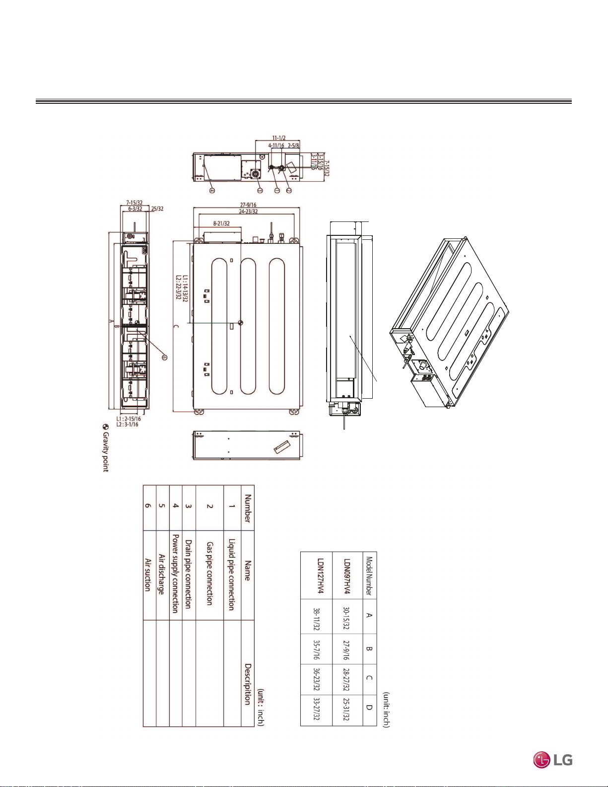
Dimensions
DUCT (LOW STATIC) INDOOR UNITS
Figure 121:LDN097HV4, LDN127HV4, and LDN187HV4 Dimensions.
Supply Air
5-5/16 1-3/8
13/16
D
Top
LDN187HV4
Due to our policy of continuous product innovation, some specications may change without notication.
©LG Electronics U.S.A., Inc., Englewood Cliffs, NJ. All rights reserved. “LG” is a registered trademark of LG Corp.
96 | DUCT (LOW STATIC)
Multi F and Multi F MAX Indoor Unit Engineering Manual
MULTI
F
MAX
MULTI
F

DUCT (LOW STATIC) INDOOR UNITS
Cooling Capacity Table
Table 41: Multi F Ceiling-Concealed Duct (Low Static) Indoor Units Cooling Capacity Table.
TC = Total Capacity (kBtu/h).
SHC: Sensible Heat Capacity (kBtu/h).
Nominal capacity as rated 0 ft. above sea level and a 0 ft. level difference between outdoor and indoor units. Corresponding refrigerant piping length is accordance with standard length of each outdoor unit.
Nominal cooling capacity rating obtained with air entering the indoor unit at 80ºF dry bulb (DB) and 67ºF wet bulb (WB), and outdoor ambient conditions of 95ºF dry bulb (DB) and 75ºF wet bulb (WB).
The shaded table columns and rows indicate reference data. When operating at this temperature, these values can be different if the system is not running consistently.
Model No. /
Nominal Capacity
of Indoor Unit
(Btu/h)
Outdoor Air
Temp.
(°F DB)
Indoor Air Temp. °F DB / °F WB
68 / 57 73 / 61 77 / 64 80 / 67 86 / 72 90 / 75
TC SHC TC SHC TC SHC TC SHC TC SHC TC SHC
LDN097HV4
9,000
14 8.82 7.55 9.37 7.98 9.92 7.72 10.31 7.89 11.01 7.95 11.56 8.10
20 8.82 7.61 9.36 8.04 9.91 7.78 10.31 7.95 11.01 8.01 11.55 8.17
25 8.81 7.67 9.36 8.10 9.90 7.84 10.30 8.01 11.00 8.08 11.54 8.23
30 8.80 7.73 9.35 8.16 9.90 7.90 10.29 8.07 10.99 8.14 11.54 8.29
35 8.80 7.79 9.34 8.22 9.89 7.96 10.28 8.13 10.98 8.20 11.53 8.36
40 8.79 7.84 9.33 8.29 9.88 8.02 10.27 8.19 10.97 8.26 11.52 8.42
45 8.78 7.90 9.33 8.35 9.87 8.08 10.27 8.25 10.96 8.32 11.51 8.48
50 8.78 7.96 9.32 8.41 9.87 8.14 10.26 8.31 10.96 8.38 11.50 8.54
55 8.77 8.02 9.31 8.47 9.86 8.20 10.25 8.38 10.95 8.45 11.49 8.61
60 8.76 8.08 9.31 8.53 9.85 8.26 10.24 8.44 10.94 8.51 11.48 8.67
65 8.76 8.14 9.30 8.59 9.84 8.32 10.24 8.50 10.93 8.57 11.47 8.73
70 8.75 8.19 9.29 8.66 9.84 8.38 10.23 8.56 10.92 8.63 11.47 8.79
75 8.54 8.06 9.08 8.52 9.62 8.26 10.01 8.44 10.71 8.53 11.25 8.69
80 8.33 7.92 8.87 8.39 9.41 8.14 9.80 8.33 10.49 8.42 11.03 8.59
85 8.12 7.78 8.66 8.25 9.20 8.02 9.59 8.20 10.28 8.30 10.82 8.48
90 7.91 7.63 8.45 8.10 8.99 7.89 9.37 8.08 10.06 8.19 10.60 8.37
95 7.68 7.55 8.22 8.03 8.75 7.83 9.00 7.90 9.83 8.14 10.36 8.34
100 7.50 7.35 8.03 7.83 8.57 7.64 8.88 7.78 9.64 7.97 10.17 8.16
105 7.31 7.15 7.84 7.63 8.38 7.45 8.77 7.66 9.45 7.79 9.99 7.99
110 7.12 6.90 7.66 7.38 8.19 7.22 8.58 7.43 9.26 7.57 9.80 7.77
115 6.94 6.69 7.47 7.17 8.01 7.03 8.39 7.24 9.08 7.39 9.61 7.60
118 6.82 6.65 7.36 7.13 7.89 7.00 8.28 7.21 8.96 7.37 9.50 7.58
122 6.79 6.63 7.32 7.11 7.86 6.98 8.24 7.19 8.93 7.36 9.46 7.57
LDN127HV4
12,000
14 11.76 9.94 12.49 10.50 13.22 10.17 13.75 10.38 14.69 10.47 15.42 10.67
20 11.75 10.02 12.48 10.58 13.21 10.25 13.74 10.46 14.67 10.55 15.40 10.75
25 11.75 10.09 12.48 10.66 13.20 10.33 13.73 10.54 14.66 10.63 15.39 10.83
30 11.74 10.17 12.47 10.75 13.19 10.40 13.72 10.62 14.65 10.71 15.38 10.92
35 11.73 10.25 12.46 10.83 13.18 10.48 13.71 10.70 14.64 10.79 15.37 11.00
40 11.72 10.33 12.45 10.91 13.17 10.56 13.70 10.79 14.63 10.88 15.36 11.08
45 11.71 10.40 12.44 10.99 13.16 10.64 13.69 10.87 14.62 10.96 15.35 11.16
50 11.70 10.48 12.43 11.07 13.15 10.72 13.68 10.95 14.61 11.04 15.33 11.25
55 11.69 10.56 12.42 11.15 13.14 10.80 13.67 11.03 14.60 11.12 15.32 11.33
60 11.68 10.63 12.41 11.23 13.13 10.88 13.66 11.11 14.59 11.20 15.31 11.41
65 11.67 10.71 12.40 11.31 13.12 10.96 13.65 11.19 14.57 11.28 15.30 11.49
70 11.66 10.79 12.39 11.40 13.11 11.03 13.64 11.27 14.56 11.36 15.29 11.58
75 11.38 10.61 12.11 11.22 12.83 10.88 13.35 11.12 14.27 11.22 15.00 11.45
80 11.10 10.43 11.82 11.05 12.55 10.72 13.07 10.96 13.99 11.08 14.71 11.31
85 10.83 10.24 11.54 10.86 12.26 10.55 12.78 10.80 13.70 10.93 14.42 11.17
90 10.55 10.04 11.26 10.67 11.98 10.38 12.50 10.63 13.42 10.78 14.13 11.02
95 10.25 9.94 10.96 10.57 11.67 10.30 12.00 10.40 13.10 10.72 13.81 10.97
100 10.00 9.67 10.71 10.31 11.42 10.06 11.84 10.24 12.85 10.49 13.56 10.75
105 9.75 9.41 10.46 10.04 11.17 9.81 11.69 10.08 12.60 10.26 13.31 10.52
110 9.50 9.09 10.21 9.72 10.92 9.51 11.44 9.78 12.35 9.97 13.07 10.24
115 9.25 8.81 9.96 9.44 10.67 9.26 11.19 9.53 12.10 9.73 12.82 10.00
118 9.10 8.75 9.81 9.39 10.52 9.21 11.04 9.49 11.95 9.70 12.67 9.98
122 9.05 8.73 9.76 9.37 10.48 9.19 10.99 9.47 11.90 9.69 12.62 9.97
DUCT (LOW STATIC) | 97
Ceiling-Concealed Duct (Low Static)
Due to our policy of continuous product innovation, some specications may change without notication.
©LG Electronics U.S.A., Inc., Englewood Cliffs, NJ. All rights reserved. “LG” is a registered trademark of LG Corp.
MULTI
F
MAX
MULTI
F

Model No. /
Nominal Capacity
of Indoor Unit
(Btu/h)
Outdoor Air
Temp.
(°F DB)
Indoor Air Temp. °F DB / °F WB
68 / 57 73 / 61 77 / 64 80 / 67 86 / 72 90 / 75
TC SHC TC SHC TC SHC TC SHC TC SHC TC SHC
LDN187HV4
18,000
14 17.65 13.09 18.74 13.83 19.84 13.39 20.63 13.67 22.03 13.79 23.12 14.05
20 17.63 13.20 18.73 13.94 19.82 13.50 20.61 13.78 22.01 13.90 23.11 14.16
25 17.62 13.30 18.71 14.05 19.81 13.60 20.60 13.89 22.00 14.01 23.09 14.27
30 17.60 13.40 18.70 14.16 19.79 13.71 20.58 13.99 21.98 14.11 23.07 14.38
35 17.59 13.50 18.68 14.26 19.78 13.81 20.57 14.10 21.96 14.22 23.05 14.49
40 17.58 13.60 18.67 14.37 19.76 13.91 20.55 14.21 21.94 14.33 23.04 14.60
45 17.56 13.71 18.66 14.48 19.75 14.02 20.53 14.31 21.93 14.43 23.02 14.71
50 17.55 13.81 18.64 14.58 19.73 14.12 20.52 14.42 21.91 14.54 23.00 14.82
55 17.54 13.91 18.63 14.69 19.72 14.23 20.50 14.52 21.89 14.65 22.98 14.92
60 17.52 14.01 18.61 14.80 19.70 14.33 20.49 14.63 21.88 14.75 22.97 15.03
65 17.51 14.11 18.60 14.90 19.69 14.43 20.47 14.74 21.86 14.86 22.95 15.14
70 17.50 14.21 18.58 15.01 19.67 14.53 20.46 14.84 21.84 14.97 22.93 15.25
75 17.08 13.98 18.16 14.78 19.24 14.33 20.03 14.64 21.41 14.78 22.50 15.08
80 16.66 13.74 17.74 14.55 18.82 14.12 19.60 14.44 20.98 14.60 22.06 14.90
85 16.24 13.49 17.32 14.30 18.40 13.90 19.17 14.23 20.55 14.40 21.63 14.71
90 15.82 13.23 16.90 14.06 17.97 13.68 18.75 14.01 20.12 14.20 21.20 14.52
95 15.37 13.09 16.44 13.93 17.51 13.57 18.00 13.70 19.65 14.12 20.72 14.46
100 14.99 12.74 16.06 13.58 17.13 13.25 17.77 13.49 19.28 13.82 20.35 14.16
105 14.62 12.39 15.69 13.23 16.76 12.93 17.53 13.28 18.90 13.52 19.97 13.86
110 14.24 11.97 15.32 12.80 16.39 12.53 17.16 12.88 18.53 13.13 19.60 13.48
115 13.87 11.61 14.94 12.44 16.01 12.19 16.79 12.55 18.15 12.82 19.22 13.18
118 13.65 11.53 14.72 12.36 15.79 12.13 16.56 12.50 17.93 12.77 19.00 13.14
122 13.57 11.50 14.64 12.34 15.71 12.11 16.49 12.48 17.85 12.76 18.92 13.13
Table 42: Multi F Ceiling-Concealed Duct (Low Static) Indoor Units Cooling Capacity Table (continued).
DUCT (LOW STATIC) INDOOR UNITS
Cooling Capacity Table
TC = Total Capacity (kBtu/h).
SHC: Sensible Heat Capacity (kBtu/h).
Nominal capacity as rated 0 ft. above sea level and a 0 ft. level difference between outdoor and indoor units. Corresponding refrigerant piping length is accordance with standard length of each outdoor unit.
Nominal cooling capacity rating obtained with air entering the indoor unit at 80ºF dry bulb (DB) and 67ºF wet bulb (WB), and outdoor ambient conditions of 95ºF dry bulb (DB) and 75ºF wet bulb (WB).
The shaded table columns and rows indicate reference data. When operating at this temperature, these values can be different if the system is not running consistently.
Due to our policy of continuous product innovation, some specications may change without notication.
©LG Electronics U.S.A., Inc., Englewood Cliffs, NJ. All rights reserved. “LG” is a registered trademark of LG Corp.
98 | DUCT (LOW STATIC)
Multi F and Multi F MAX Indoor Unit Engineering Manual
MULTI
F
MAX
MULTI
F
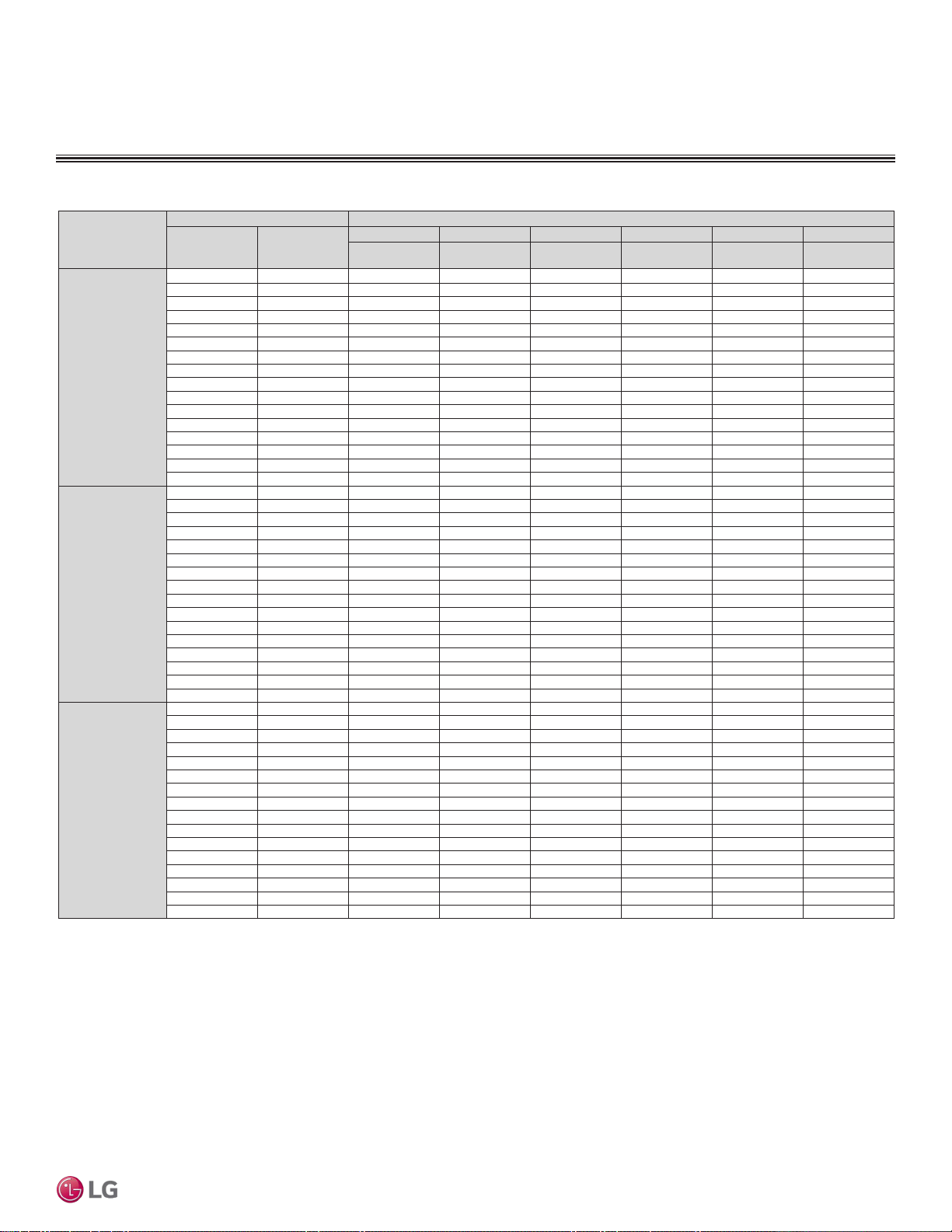
Table 43: Multi F Ceiling-Concealed Duct (Low Static) Indoor Units Heating Capacity Table.
DUCT (LOW STATIC) INDOOR UNITS
Heating Capacity Table
Model No. /
Nominal Capacity of
Indoor Unit
(Btu/h)
Outdoor Air Temp. Indoor Air Temp. °F DB
°F DB °F WB
61 64 68 70 72 75
TC TC TC TC TC TC
LDN097HV4
9,000
0 -0.4 5.35 5.28 5.23 5.20 5.12 4.90
5 4.5 6.03 5.95 5.90 5.88 5.80 5.58
10 9 6.71 6.63 6.58 6.56 6.48 6.26
17 15 7.61 7.54 7.49 7.46 7.39 7.14
20 19 7.95 7.88 7.83 7.80 7.72 7.46
25 23 8.52 8.44 8.39 8.37 8.29 7.99
30 28 9.01 8.93 8.88 8.86 8.78 8.52
35 32 9.50 9.42 9.37 9.34 9.27 9.04
40 36 9.94 9.86 9.81 9.78 9.71 9.48
45 41 10.37 10.30 10.25 10.22 10.15 9.92
47 43 10.55 10.48 10.43 10.40 10.32 10.10
50 46 10.72 10.64 10.59 10.57 10.49 10.24
55 51 11.00 10.93 10.88 10.85 10.78 10.48
60 56 11.00 10.93 10.88 10.85 10.78 10.52
63 59 11.00 10.93 10.88 10.85 10.78 10.55
68 64 11.00 10.93 10.88 10.85 10.78 10.60
LDN127HV4
12,000
0 -0.4 7.10 7.00 6.93 6.90 6.80 6.50
5 4.5 8.00 7.90 7.83 7.80 7.70 7.40
10 9 8.90 8.80 8.73 8.70 8.60 8.30
17 15 10.10 10.00 9.93 9.90 9.80 9.48
20 19 10.55 10.45 10.38 10.35 10.25 9.90
25 23 11.30 11.20 11.13 11.10 11.00 10.60
30 28 11.95 11.85 11.78 11.75 11.65 11.30
35 32 12.60 12.50 12.43 12.40 12.30 12.00
40 36 13.18 13.08 13.02 12.98 12.88 12.58
45 41 13.77 13.67 13.60 13.57 13.47 13.17
47 43 14.00 13.90 13.83 13.80 13.70 13.40
50 46 14.23 14.13 14.06 14.03 13.93 13.59
55 51 14.60 14.50 14.43 14.40 14.30 13.90
60 56 14.60 14.50 14.43 14.40 14.30 13.96
63 59 14.60 14.50 14.43 14.40 14.30 14.00
68 64 14.60 14.50 14.43 14.40 14.30 14.06
LDN187HV4
18,000
0 -0.4 10.70 10.55 10.45 10.40 10.25 9.80
5 4.5 12.06 11.91 11.81 11.76 11.61 11.15
10 9 13.41 13.26 13.16 13.11 12.96 12.51
17 15 15.22 15.07 14.97 14.92 14.77 14.29
20 19 15.90 15.75 15.65 15.60 15.45 14.92
25 23 17.03 16.88 16.78 16.73 16.58 15.98
30 28 18.01 17.86 17.76 17.71 17.56 17.03
35 32 18.99 18.84 18.74 18.69 18.54 18.09
40 36 19.87 19.72 19.62 19.57 19.42 18.97
45 41 20.75 20.60 20.50 20.45 20.30 19.85
47 43 21.10 20.95 20.85 20.80 20.65 20.20
50 46 21.44 21.29 21.19 21.14 20.99 20.48
55 51 22.01 21.86 21.75 21.70 21.55 20.95
60 56 22.01 21.86 21.75 21.70 21.55 21.04
63 59 22.01 21.86 21.75 21.70 21.55 21.10
68 64 22.01 21.86 21.75 21.70 21.55 21.20
TC = Total Capacity (kBtu/h).
Nominal capacity as rated 0 ft. above sea level and a 0 ft. level difference between outdoor and indoor units. Corresponding refrigerant piping length is accordance with standard length of each outdoor unit.
Nominal heating capacity rating obtained with air entering the indoor unit at 70ºF dry bulb (DB) and 60ºF wet bulb (WB), and outdoor ambient conditions of 47ºF dry bulb (DB) and 43ºF wet bulb (WB).
DUCT (LOW STATIC) | 99
Ceiling-Concealed Duct (Low Static)
Due to our policy of continuous product innovation, some specications may change without notication.
©LG Electronics U.S.A., Inc., Englewood Cliffs, NJ. All rights reserved. “LG” is a registered trademark of LG Corp.
MULTI
F
MAX
MULTI
F
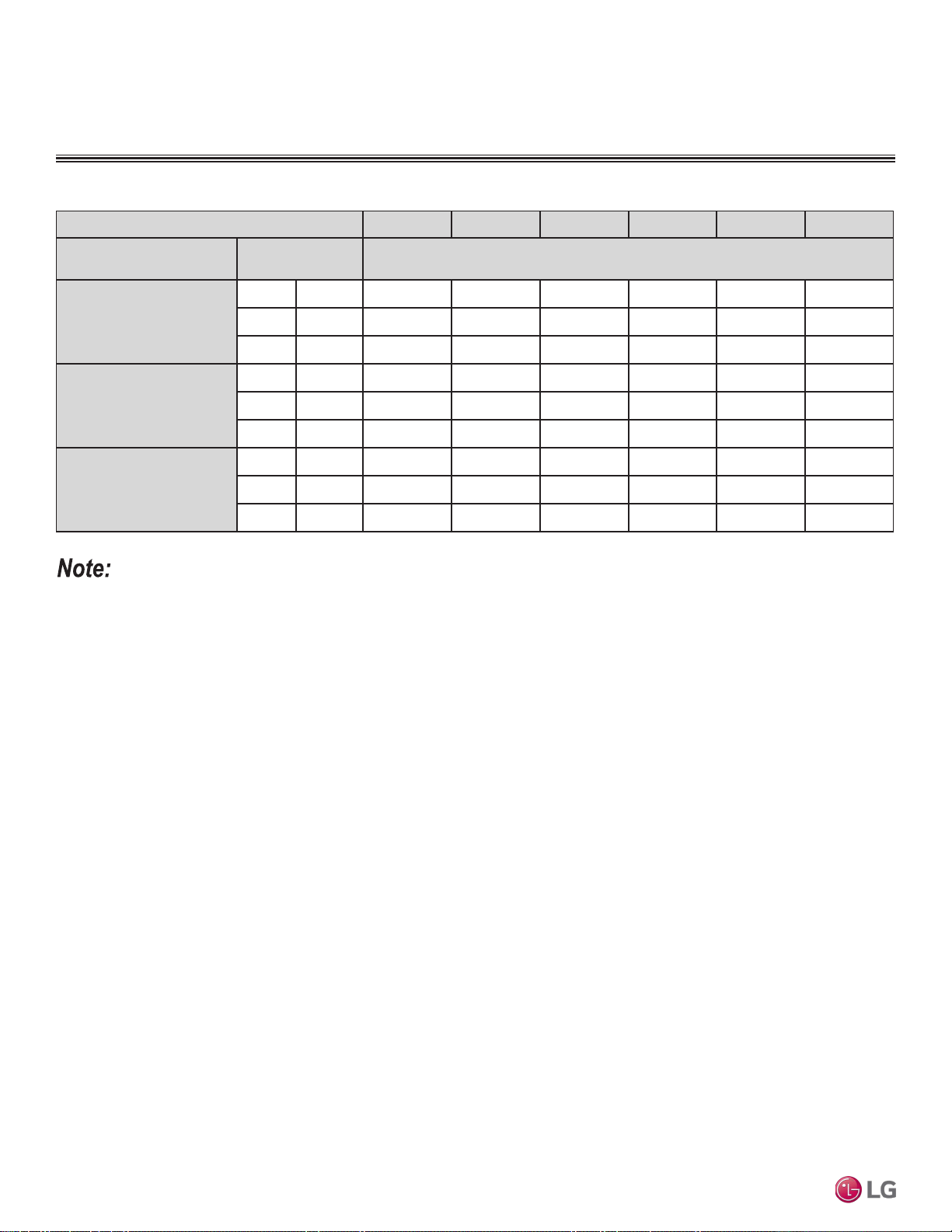
DUCT (LOW STATIC) INDOOR UNITS
External Static Pressure
Table 44: Multi F Ceiling-Concealed Duct (Low Static) External Static Pressure Setting Values Table.
Static Pressure (in. wg) 0.0 0.04 0.08 0.12 0.16 0.20
Model No. / Nominal Capacity
of Indoor Unit (Btu/h)
Airflow Rate / CFM Setting Value
LDN097HV4
9,000
High 318 98 103 108 116 123 130
Mid 247 82 88 94 102 110 118
Low 194 69 76 83 91 99 109
LDN127HV4
12,000
High 353 95 99 104 109 116 124
Mid 300 86 91 96 101 108 116
Low 247 78 82 87 93 100 108
LDN187HV4
18,000
High 530 123 125 129 134 141 145
Mid 441 109 112 117 123 129 136
Low 353 95 99 104 109 116 124
• To get the desired air flow and external static pressure combination, use the setting value from the table. Using a setting value other
than that listed in the table will not provide the desired combination.
• Table data is based at 230V. Air flow rate varies according to voltage fluctuation.
Due to our policy of continuous product innovation, some specications may change without notication.
©LG Electronics U.S.A., Inc., Englewood Cliffs, NJ. All rights reserved. “LG” is a registered trademark of LG Corp.
100 | DUCT (LOW STATIC)
Multi F and Multi F MAX Indoor Unit Engineering Manual
MULTI
F
MAX
MULTI
F
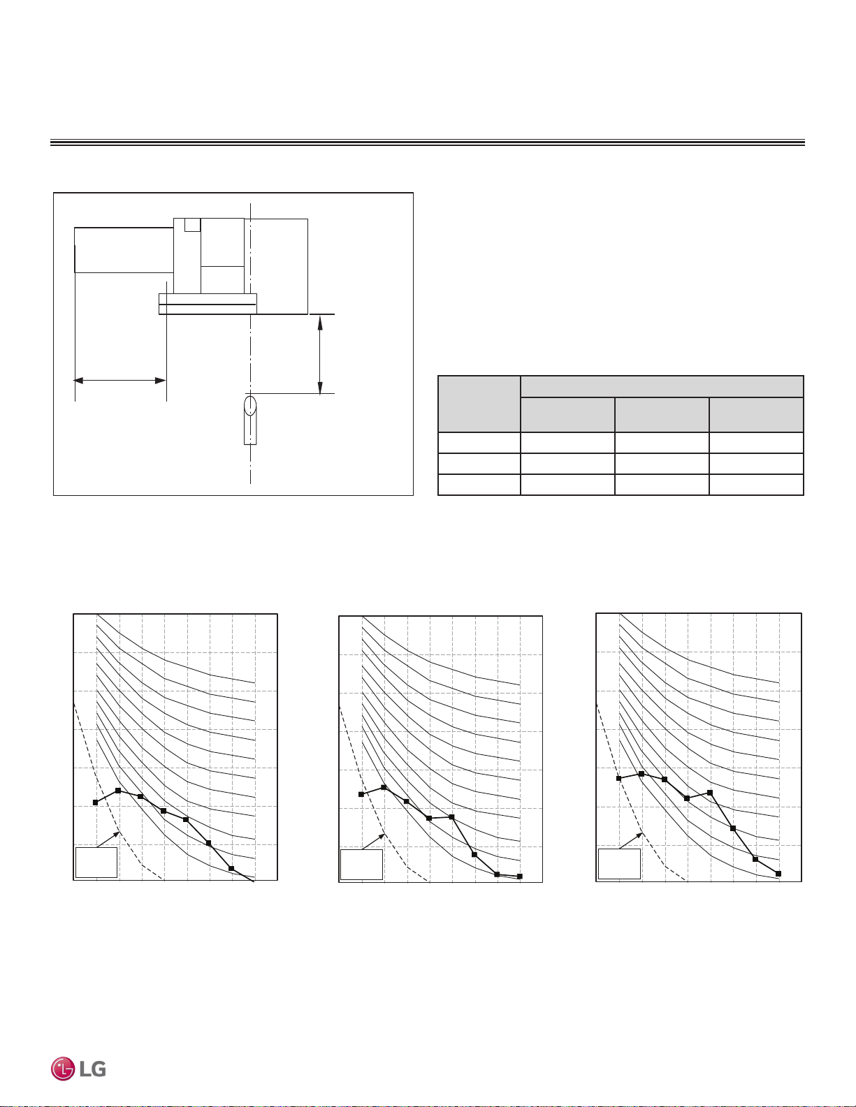
DUCT (LOW STATIC) INDOOR UNITS
• Measurements taken with no attenuation and units operating at full
load normal operating condition.
• Sound level will vary depending on a range of factors such as
construction (acoustic absorption coefficient) of particular area in
which the equipment is installed.
• Sound power levels are measured in dB(A).
• Tested in anechoic chamber per ISO Standard 3745.
Model No.
Sound Pressure Levels (dB[A]) (Cooling and Heating)
High Fan Speed
Medium Fan
Speed
Low Fan Speed
LDN097HV4
30 26 23
LDN127HV4
31 28 27
LDN187HV4 36 34 31
Figure 122:Sound Pressure Level Measurement Location.
Table 45:Sound Pressure Levels (dB[A]).
Figure 123:Sound Pressure Level Diagrams.
Acoustic Data
4.9 ft.
Ceiling
6.6 ft.
Microphone
Octave Band Center Frequency (Hz)
Octave Band Sound Pressure Level (0dB = 20μPa)
10
20
30
40
50
60
70
80
63 125 250 500 1000 2000 4000 8000
NC-15
NC-20
NC-25
NC-30
NC-35
NC-40
NC-45
NC-50
NC-55
NC-60
NC-65
Approximate
Hearing
Threshold
Octave Band Center Frequency (Hz)
Octave Band Sound Pressure Level (0dB = 20μPa)
10
20
30
40
50
60
70
80
63 125 250 500 1000 2000 4000 8000
NC-15
NC-20
NC-25
NC-30
NC-35
NC-40
NC-45
NC-50
NC-55
NC-60
NC-65
Approximate
Hearing
Threshold
LDN097HV4LDN127HV4
Octave Band Center Frequency (Hz)
Octave Band Sound Pressure Level (0dB = 20μPa)
10
20
30
40
50
60
70
80
63 125 250 500 1000 2000 4000 8000
NC-15
NC-20
NC-25
NC-30
NC-35
NC-40
NC-45
NC-50
NC-55
NC-60
NC-65
Approximat e
Hearing
Threshold
LDN187HV4
DUCT (LOW STATIC) | 101
Ceiling-Concealed Duct (Low Static)
Due to our policy of continuous product innovation, some specications may change without notication.
©LG Electronics U.S.A., Inc., Englewood Cliffs, NJ. All rights reserved. “LG” is a registered trademark of LG Corp.
MULTI
F
MAX
MULTI
F
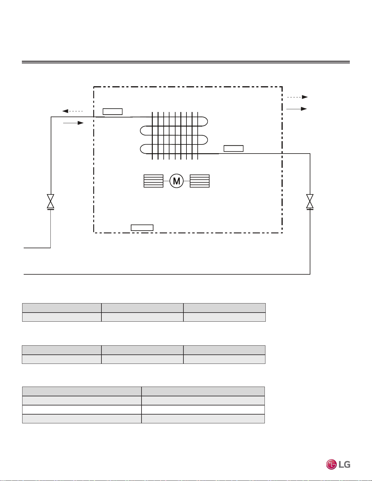
DUCT (LOW STATIC) INDOOR UNITS
Refrigerant Flow Diagram
Figure 124:LDN097HV4 Refrigerant Flow Diagram.
Table 46:Multi F Ceiling-Concealed Duct (Low Static) LDN097HV4 Indoor Unit Refrigerant Pipe Sizes.
Model No. Vapor (inch) Liquid (inch)
LDN097HV4 Ø3/8 Ø1/4
Table 47:Multi F Ceiling-Concealed Duct (Low Static) LDN097HV4 Refrigerant Pipe Connections.
Description (Based on Cooling Mode) PCB Connector
Indoor Air Temperature Thermistor CN-ROOM
Evaporator Inlet Temperature Thermistor CN-PIPE/IN
Evaporator Outlet Temperature Thermistor CN-PIPE/OUT
Indoor Unit
: Cooling
: Heating
M
Sirocco Fan
Indoor Air
Temperature
Thermistor
Evaporator
Outlet
Temperature
Thermistor
Evaporator
Inlet
Temperature
Thermistor
Table 48:Multi F Ceiling-Concealed Duct (Low Static) LDN097HV4 Indoor Unit Thermistor Details.
Model No. Vapor (inch) Liquid (inch)
LDN097HV4 Ø3/8 Ø1/4
Due to our policy of continuous product innovation, some specications may change without notication.
©LG Electronics U.S.A., Inc., Englewood Cliffs, NJ. All rights reserved. “LG” is a registered trademark of LG Corp.
102 | DUCT (LOW STATIC)
Multi F and Multi F MAX Indoor Unit Engineering Manual
MULTI
F
MAX
MULTI
F
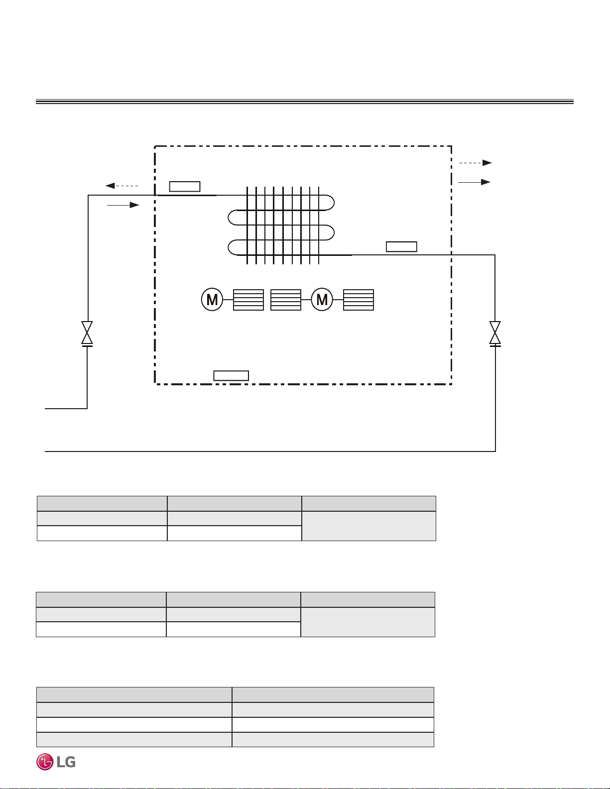
Figure 125:LDN127HV4 and LDN187HV4 Refrigerant Flow Diagram.
DUCT (LOW STATIC) INDOOR UNITS
Refrigerant Flow Diagrams
Table 49: Multi F Ceiling-Concealed Duct (Low Static) LDN127HV4 and LDN187HV4 Indoor Unit Refrigerant
Pipe Sizes.
Model No. Vapor (inch) Liquid (inch)
LDN127HV4 Ø3/8
Ø1/4
LDN187HV4 Ø1/2
Table 50: Multi F Ceiling-Concealed Duct (Low Static) LDN127HV4 and LDN187HV4 Indoor Unit Refrigerant
Pipe Connections.
Description (Based on Cooling Mode) PCB Connector
Indoor Air Temperature Thermistor CN-ROOM
Evaporator Inlet Temperature Thermistor CN-PIPE/IN
Evaporator Outlet Temperature Thermistor CN-PIPE/OUT
Indoor Unit
: Cooling
: Heating
MM
Sirocco Fan
Indoor Air
Temperature
Thermistor
Evaporator
Outlet
Temperature
Thermistor
Evaporator
Inlet
Temperature
Thermistor
Model No. Vapor (inch) Liquid (inch)
LDN127HV4 Ø3/8
Ø1/4
LDN187HV4 Ø1/2
Table 51: Multi F Ceiling-Concealed Duct (Low Static) LDN127HV4 and LDN187HV4 Indoor Unit Thermistor
Details.
DUCT (LOW STATIC) | 103
Ceiling-Concealed Duct (Low Static)
Due to our policy of continuous product innovation, some specications may change without notication.
©LG Electronics U.S.A., Inc., Englewood Cliffs, NJ. All rights reserved. “LG” is a registered trademark of LG Corp.
MULTI
F
MAX
MULTI
F
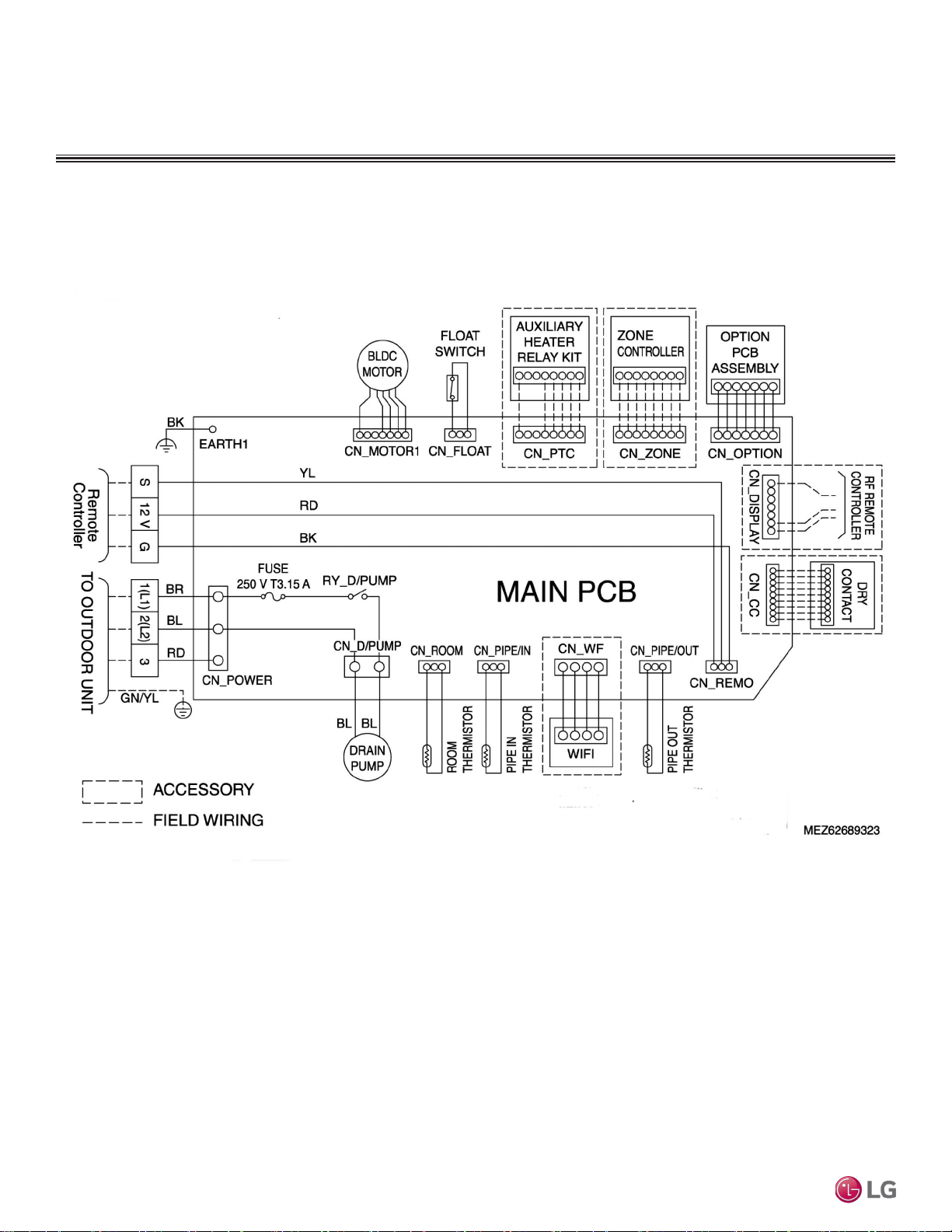
Wiring Diagram
DUCT (LOW STATIC) INDOOR UNITS
Figure 126:Multi F Ceiling-Concealed Duct (Low Static) LDN097HV4 Indoor Units Wiring Diagram.
Due to our policy of continuous product innovation, some specications may change without notication.
©LG Electronics U.S.A., Inc., Englewood Cliffs, NJ. All rights reserved. “LG” is a registered trademark of LG Corp.
104 | DUCT (LOW STATIC)
Multi F and Multi F MAX Indoor Unit Engineering Manual
MULTI
F
MAX
MULTI
F
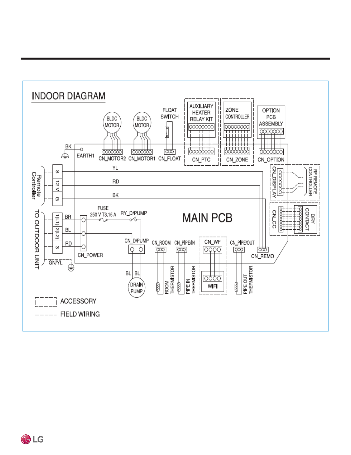
Wiring Diagram
Figure 127:Multi F Ceiling-Concealed Duct (Low Static) LDN127HV4 and LDN187HV4 Indoor Units Wiring Diagram.
DUCT (LOW STATIC) INDOOR UNITS
MEZ62689324 11/18
DUCT (LOW STATIC) | 105
Ceiling-Concealed Duct (Low Static)
Due to our policy of continuous product innovation, some specications may change without notication.
©LG Electronics U.S.A., Inc., Englewood Cliffs, NJ. All rights reserved. “LG” is a registered trademark of LG Corp.
MULTI
F
MAX
MULTI
F
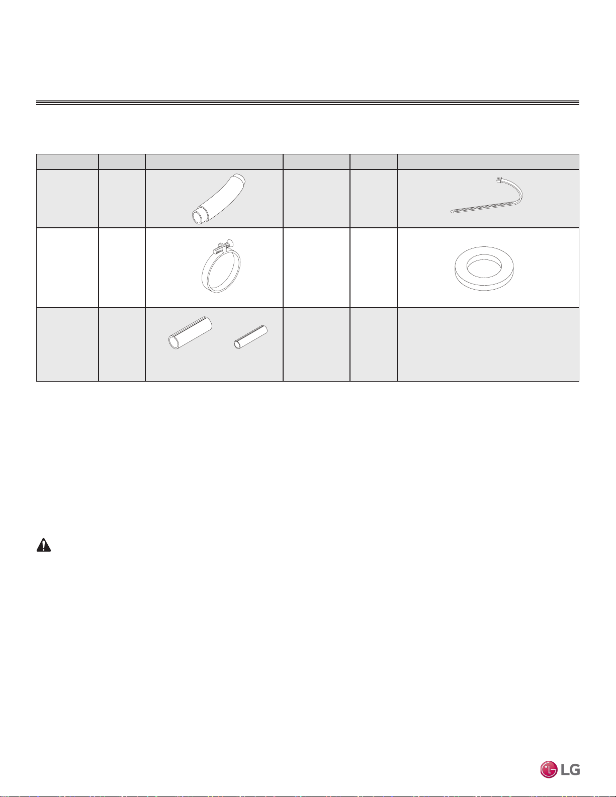
Factory Supplied Parts and Materials
DUCT (LOW STATIC) INDOOR UNITS
Factory Supplied Parts
Part Quantity Image Part Quantity Image
Drain Hose One (1) Zip Ties Four (4)
Metal Clamp Two (2)
Washers for
Hanging
Brackets
Eight (8)
Insulation for
Fittings
One (1) Set
Factory Supplied Materials
• Owner’s Manual
• Installation Manual
Required Tools
• Level
• Screwdriver
• Electric drill
• Hole core drill
• Flaring tool set
• Torque wrenches
• Hexagonal wrench
• Gas-leak detector
• Thermometer
Table 52: Parts Table.
For Vapor Piping For Liquid Piping
WARNING
Installation work must be performed by trained personnel and in accordance with national wiring standards and all local or other applicable codes.
Improper installation can result in re, electric shock, physical injury, or death.
Note:
Read all instructions before installing this product. Become familiar with the unit’s components and connections, and the order of installation. Incorrect
installation can degrade or prevent proper operation.
Due to our policy of continuous product innovation, some specications may change without notication.
©LG Electronics U.S.A., Inc., Englewood Cliffs, NJ. All rights reserved. “LG” is a registered trademark of LG Corp.
106 | DUCT (LOW STATIC)
Multi F and Multi F MAX Indoor Unit Engineering Manual
MULTI
F
MAX
MULTI
F
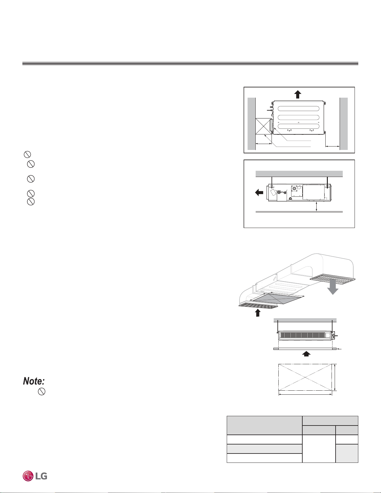
Installation and Best Layout Practices
Selecting the Best Location
Do’s
• Place the unit where air circulation will not be blocked.
• Place the unit where drainage can be obtained easily.
• Place the unit where noise prevention is taken into consideration.
• Ensure there is sufcient strength to bear the load of the indoor unit.
• Ensure there is sufficient maintenance space.
• Locate the indoor unit in a location that is level, and where it can be easily
connected to the outdoor unit / branch distribution unit.
DUCT (LOW STATIC) INDOOR UNITS
Figure 128:General Installation Guidelines.
Model / Capacity (Btu/h)
Dimensions (in.)
A B
LDN097HV4 / 9,000
31-1/2
31-1/2
LDN127HV4 / 12,000
39-3/8
LDN187HV4 / 18,000
Table 53:General Access Panel Dimensions.
Installing in an Area Exposed to Unconditioned Air
In some installation applications, areas(floors, walls) in some rooms will be
exposed to unconditioned air (room will be above or next to an unheated garage
or storeroom). To countermeasure:
• Verify that carpet is or will be installed (carpet will increase the temperature by
three degrees).
• Add insulation between the floor joists.
• Install radiant heat or another type of heating system to the floor.
Installing in an Area with High Humidity Levels
If the environment is prone to humidity levels of 80% or more (near the ocean,
lakes, etc.) or where steam could collect in the plenum:
• Install additional insulation to the indoor unit (glass wool insulation >13/32
inches thick).
• Install additional insulation to the refrigerant piping (insulation >13/16 inches
thick).
• Seal all gaps between the indoor unit and the ceiling tiles (make the area air
tight) so that humidity does not transfer from the plenum to the conditioned
space. Also, add a ceiling grille for ventilation.
Access Opening
(
23-5/8
x
23-5/8
)
Control box
H = ≤25/32
• "H" dimension is necessary to ensure a slope is included for
condensate drainage.
Side view
23-5/8
23-5/8
(Unit : Inch)
(Unit : Inch)
Top view
A (Min)
Ceiling
Service Space
A
B
B (Min)
Figure 129:Service / Access Panel Dimensions.
Don’ts
• Do not install the unit near a heat or steam source, or where considerable
amounts of oil, iron powder, or flour are used.
• Do not install the unit where sulfuric acid and flammable or corrosive gases
are generated, vented into, or stored.
• Do not install the unit near high-frequency generators.
• Do not install the unit near a doorway.
The unit will be damaged, will malfunction, and / or will not operate as
designed if installed in any of the conditions listed.
• Indoor units (IDUs) must not be placed in an environment where the
IDUs will be exposed to harmful volatile organic compounds (VOCs) or in
environments where there is improper air make up or supply or inadequate
ventilation. If there are concerns about VOCs in the environment where the
IDUs are installed, proper air make up or supply and/or adequate ventilation
must be provided. Additionally, in buildings where IDUs will be exposed to
VOCs, consider a third party factory-applied epoxy coating to the fan coils
for each IDU where the entire coil is dipped, not sprayed.
• If the unit is installed near a body of water, the installation parts are at risk
of corroding. Appropriate anti-corrosion methods must be taken for the unit
and all installation parts.
DUCT (LOW STATIC) | 107
Ceiling-Concealed Duct (Low Static)
Due to our policy of continuous product innovation, some specications may change without notication.
©LG Electronics U.S.A., Inc., Englewood Cliffs, NJ. All rights reserved. “LG” is a registered trademark of LG Corp.
MULTI
F
MAX
MULTI
F
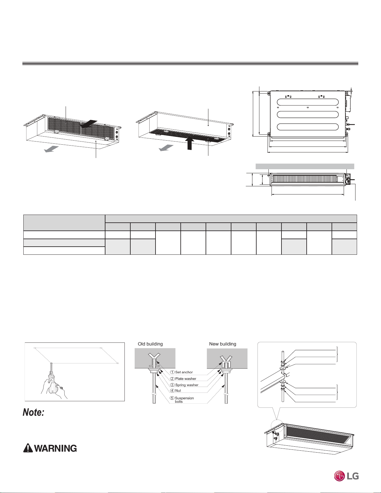
Model / Capacity (Btu/h)
Dimensions (in.)
A B C D E F G H I J
LDN097HV4 / 9,000 28-27/32 30-13/32
24-23/32 27-9/16 1-13/32 7-15/32 25/32
25-31/32
6-3/32
27-9/16
LDN127HV4 / 12,000
36-23/32 38-9/32 33-27/32 35-7/16
LDN187HV4 / 18,000
Table 54:Indoor Unit Bolt Location Dimensions.
Figure 130:Air inlet from the back of the indoor
unit.
M10 Nut
M10 SP. washer
M10 washer
X 4
X 4
(Field
supplied)
X 4
M10 Nut
M10 SP. washer
M10 washer
X 4
X 4
(Field
supplied)
X 4
1. Select and mark the area for the suspension or console bolts
(use embedded inserts or anchor bolts in new buildings, and
hole-in-anchors in older buildings).
2. Drill the holes.
3. Add the set-anchor and the plate washer to the bolts (bolts must
be at least 13/32 inches in diameter), and then insert the bolts
into the installation area.
4. Add the plate washer, spring washer, and nut to secure the bolts
into the installation area.
5. Position the indoor unit installation plates onto the bolts. Secure
using nuts, plate washers, and spring washers. Adjust for level as
necessary.
• Unit must be installed correctly.
• Tighten the nuts and bolts to prevent the unit from falling.
Figure 132:Preparing the Installation Area.
Figure 131:Air inlet from the bottom of the
indoor unit.
Table 55:Indoor Unit Bolt Locations.
Indoor Unit s
Air Filter
Air Outlet
Air Outlet
Air Filter
Back Panel
Back Panel
DUCT (LOW STATIC) INDOOR UNITS
Duct (Low Static) Indoor Units can be installed in two ways:
Install a canvas duct to the air outlet and air inlet so that vibration from the indoor unit does not carry
to the duct or ceiling. Also, add insulation to the interior of the duct, and apply anti-vibration to the
suspension bolts.
Preparing the Installation Area and Hanging the Indoor Unit Frame
Figure 133:Console Bolt Options.
Figure 134:Hanging the Indoor Unit.
Installation and Best Layout Practices
C
E
G
D
F
I
A
J
B
H
Drainage hole
Due to our policy of continuous product innovation, some specications may change without notication.
©LG Electronics U.S.A., Inc., Englewood Cliffs, NJ. All rights reserved. “LG” is a registered trademark of LG Corp.
108 | DUCT (LOW STATIC)
Multi F and Multi F MAX Indoor Unit Engineering Manual
MULTI
F
MAX
MULTI
F
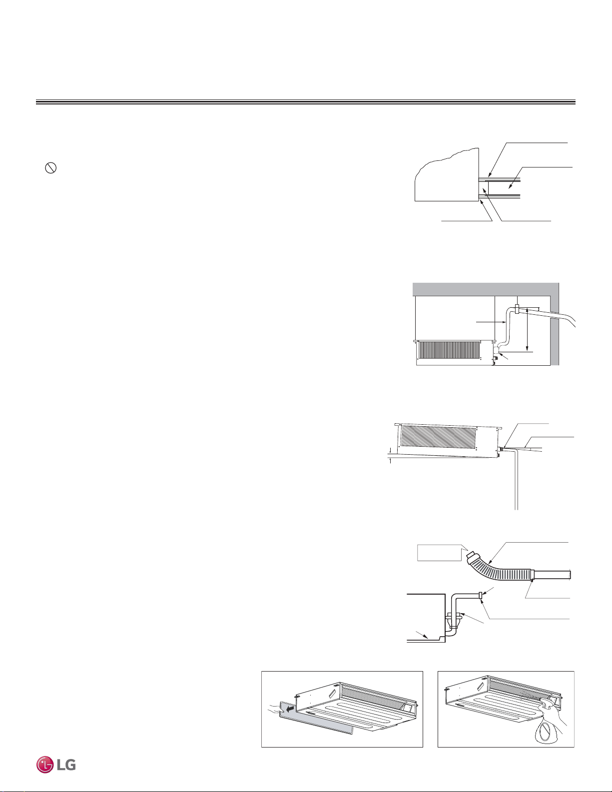
Installation and Best Layout Practices
DUCT (LOW STATIC) INDOOR UNITS
Installing the Drain System
• Drain piping must have downward gradient of at least 1/50 to 1/100; to prevent reverse flow,
slope must not be straight up and down.
• Do not damage the drain port on the indoor unit when connecting the field-supplied drain
piping.
• Drain piping specifications:
- Indoor Unit Drain Connection: 1-1/4 inch outside diameter.
- Field-Supplied Drain Piping: Polyvinyl chloride piping with 1-inch inside diameter and pipe
fittings.
Using the Drain Pump
• Maximum drain lift is 27-9/16 inches, therefore, the drain piping must be placed below
the maximum lift height.
• Field-installed drain piping must have downward gradient of at least 1/50 to 1/100; to
prevent reverse flow, slope must not be straight up and down.
Angle ≥ 1/50~1/100
Approx 3/32~5/32 inches
Drain hose
Drain HoleClose Any Gaps
Indoor Unit
Drain Pipe
Insulation
(Field Supplied)
(Field Supplied)
Figure 135:Drain Connection.
Using the Gravity Drain
Field-drain piping must have downward gradient of at least 1/50 to 1/100; to prevent
reverse flow, slope must not be straight up and down.
≤27-9/16 inch
Drain Pipe
1/50~1/100
1/50~1/100
1/50~1/100
Drain Pump
Figure 136:Indoor Unit Using Drain Pump.
Figure 137:Indoor Unit Using Gravity Drain.
Ducted (low static) indoor units have two options for condensate drainage: Using the factory-installed drain pump, or using a gravity drain.
Pour Water
Drain Pump
Drain Pan
Flexible drain hose
(accessory)
Field-Installed
Drain Piping
Glue the Joint
Drain
Port
Drain Hose Connection
Use the clip (accessory)
Indoor Unit
Checking the Drain Pump
The unit uses a drain pump to remove condensate. The pump must be tested before the
system operates.
• Connect the flexible drain hose to the field-installed drain piping; leave it as is until the
test is complete.
• Pour water into the flexible drain hose and check for leaks.
• After power wiring installation is complete, operate the drain pump to see if it sounds
and functions properly.
• After the test is complete, connect the flexible drain hose to the indoor unit drain port.
Figure 139:Checking the Drainage System.
Figure 138:Checking the Drain Pump.
Checking the Drainage System
1. Remove the air filter.
2. Check the drainage.
• Spray water on the evaporator.
• Verify that water flows through the indoor unit drain
hose without leaking.
Pump location will be different on the indoor unit.
Pump location will be different
on the indoor unit.
DUCT (LOW STATIC) | 109
Ceiling-Concealed Duct (Low Static)
Due to our policy of continuous product innovation, some specications may change without notication.
©LG Electronics U.S.A., Inc., Englewood Cliffs, NJ. All rights reserved. “LG” is a registered trademark of LG Corp.
MULTI
F
MAX
MULTI
F
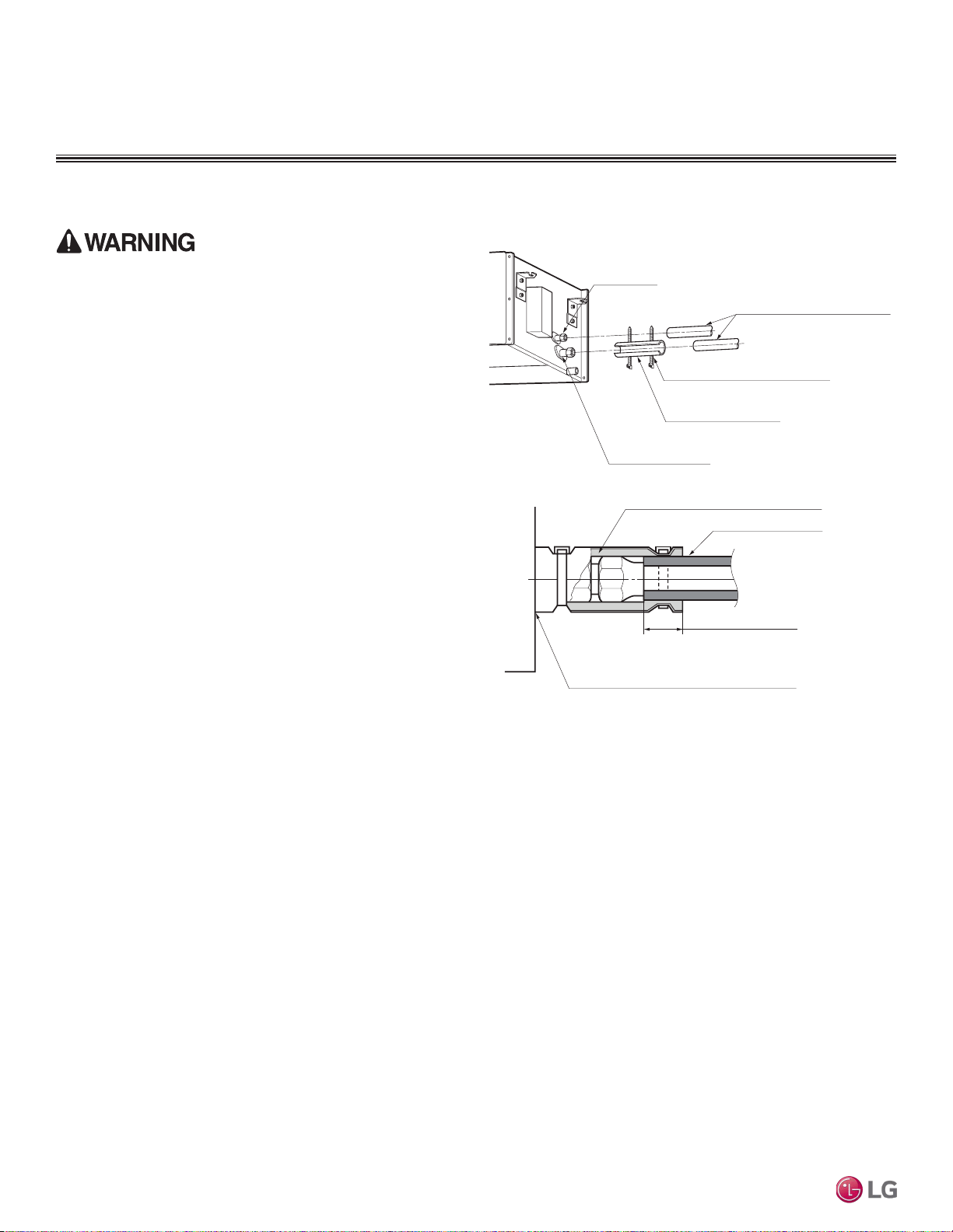
Refrigerant Piping Insulation
Field-installed vapor and liquid refrigerant piping lines must be
properly and completely covered in insulation (up to the indoor unit
piping connections). Any exposed piping will generate condensate or
will cause burns if touched. Insulation for this field-installed refriger-
ant piping must have a minimum heat resistance of 248°F.
Duct (low static) indoor units have been tested under and meet the
requirements of the “KS Conditions.” If the indoor unit is installed
and is operated at an extended period in a highly humid environment
(dew point temperature >73°F), however, condensate will form. To
prevent this phenomenon, install adiabatic glass wool insulation with
a thickness or 13/32 to 13/16 inches thick. Also, install glass wool
insulation on all indoor unit that are located in the ceiling plenum.
Drain Piping Insulation
Drain piping must have insulation a minimum of 7/32 inches thick.
DUCT (LOW STATIC) INDOOR UNITS
Installation and Best Layout Practices
Figure 140:Insulating the Piping.
Liquid Piping
Connection
Insulation for Refrigerant Piping
(Field-Supplied)
Vapor Piping Connection
Insulation
(Field-Supplied)
Clamp for Insulation
(Field-Supplied)
Ensure no gaps are present.
Overlap the Insulation at the
Connection
Insulation for Refrigerant Piping
(Field-Supplied)
Insulation for Field-Installed Piping
(Field-Supplied)
Insulating the Refrigerant and Drain Piping
Ensure all piping is insulated. Exposed piping can cause burns
if touched.
Due to our policy of continuous product innovation, some specications may change without notication.
©LG Electronics U.S.A., Inc., Englewood Cliffs, NJ. All rights reserved. “LG” is a registered trademark of LG Corp.
110 | DUCT (LOW STATIC)
Multi F and Multi F MAX Indoor Unit Engineering Manual
MULTI
F
MAX
MULTI
F
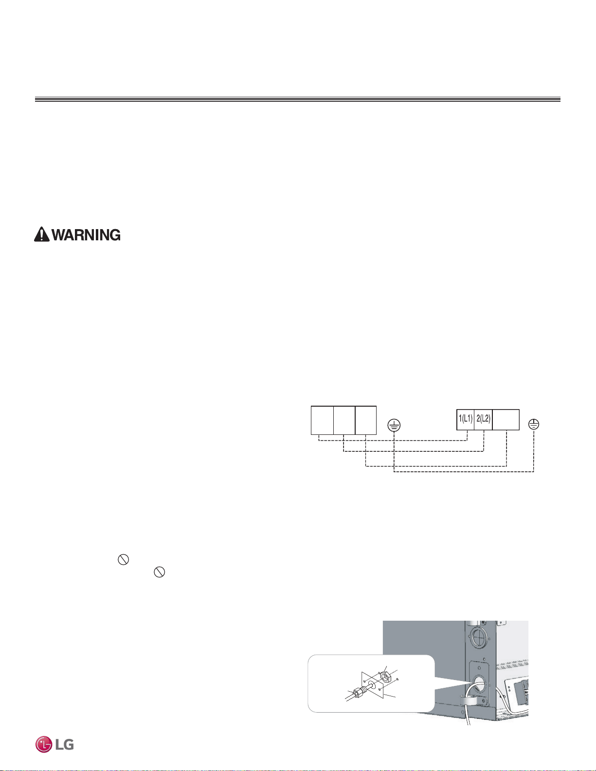
Installation and Best Layout Practices
DUCT (LOW STATIC) INDOOR UNITS
Power Wiring / Communications Cable Guidelines
Connecting the Power Wiring and Communications Cable
1. Insert the power wiring / communications cable from the out-
door unit or branch distribution unit (Multi F MAX systems only)
through the side of the indoor unit. Pass the wiring through the
designated access holes to prevent damage. To prevent electro-
magnetic interference and product malfunction, leave a space
between the power wiring and communications cable outside of
the indoor unit.
2. Connect each wire to its appropriate terminal on the indoor unit
control board. Verify that the color and terminal numbers from
the outdoor unit or branch distribution unit (Multi F MAX systems
only) wiring match the color and terminal numbers on the indoor
unit.
3. Secure the power wiring / communications cable with the cable
restraint.
4. Screw the steel clamp to the inside of the control panel.
• Place the wiring / cables in the clamp and tighten the plastic clamp to an open surface of the control panel.
• When clamping, do not apply force to the wiring connections.
• Neatly arrange the wiring, do not catch the wiring in the electric box cover, and ensure the cover firmly closes.
5. Fill in any gaps around the wiring access hole with sealant to prevent foreign particles from entering the indoor unit.
Indoor Unit Terminal Block
1(L) 2(N)
GND
3
Outdoor Unit Terminal Block or
Branch Distribution Unit Terminal Block
(Multi F MAX Systems Only)
GND
GRN /
YLW
BR
BL
RD
3 or S
Figure 141:Indoor Unit to Outdoor Unit / Branch Distribution Unit
(Multi F MAX systems only) Power Wiring / Communications Cable
Connections.
Using a Conduit
1. Remove the rubber stopper on the indoor unit. Pass the power
wiring / communications cable through the conduit, the conduit
mounting plate, and to the control panel of the indoor unit.
2. Connect the power wiring / communications cable to the indoor
unit terminal block.
3. Screw the conduit mounting plate to the indoor unit.
4. Tighten the conduit and the conduit mounting plate together.
Lock nut
Conduit
mounting
plate
Conduit
Figure 142:Exterior View of Conduit Installation.
• Follow manufacturer’s circuit diagrams in the technical manuals.
• Confirm power source specifications.
• Confirm that the electrical capacity is sufficient.
• Starting current must be maintained ±10 percent of the rated current marked on the outdoor unit name plate.
• Confirm cable thickness specifications.
• It is required that a circuit breaker is installed, especially if conditions could become wet or moist.
• Include a disconnect in the power wiring system, add an air gap contact separation of at least 1/8 inch in each active (phase) conductor.
• Loose wiring will cause unit to malfunction, overheat, and catch fire, resulting in severe injury or death.
Note:
• Terminal screws will become loose during transport. Properly tighten the terminal connections during installation.
A voltage drop will cause the following problems:
• Magnetic switch vibration, fuse breaks, or disturbance to the normal function of an overload protection device.
• Compressor will not receive the proper starting current.
DUCT (LOW STATIC) | 111
Ceiling-Concealed Duct (Low Static)
Due to our policy of continuous product innovation, some specications may change without notication.
©LG Electronics U.S.A., Inc., Englewood Cliffs, NJ. All rights reserved. “LG” is a registered trademark of LG Corp.
MULTI
F
MAX
MULTI
F
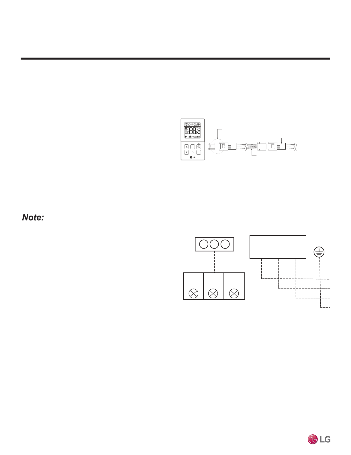
Indoor Unit Terminal Block
1(L) 2(N)
GND
3
BR
BL
RD
CN-REMO
To Wired Controller
YL
Comm.
(S)
RD
12V
Power
BK
Ground
Connections on
Wired Controller
DUCT (LOW STATIC) INDOOR UNITS
Installation and Best Layout Practices
Controller Options
Ceiling-concealed duct (low static) indoor units can be used with many LG-supplied wired controllers (sold separately). The wireless hand-
held controller (Model No. PQWRHQ0FDB) is also an optional accessory with use wired controllers.
Figure 143:PZCWRC1 LG Wired Remote Extension Cable.
Verify the connectors are properly inserted.
C/BOX Cable (Plug type)
Extension cable
To Indoor Unit
CN-REMO
Terminal
TEMP
FAN
SPEED
OPER
MODE
Figure 144:Wired Controller Connections on the Indoor Unit Terminal
Block.
When using eld-supplied controller cable, make sure to connect
the yellow to yellow (communications wire), red to red (12V power
wire), and black to black (ground wire) terminals from the remote
controller to the indoor unit terminal blocks.
Wired Controller Connections
Controllers can connect to the indoor unit in one of two different
ways.
1. LG Wired Remote Extension Cable with Molex plug (PZCWRC1;
sold separately) that connects to the CN-REMO terminal on the
indoor unit PCB.
2. Field-supplied controller cable that connects to the indoor unit
terminal block (must be at least UL2547 or UL1007, 22 AWG,
two-core, one-shield core, at least FT-6 rated if local electric and
building codes require plenum cable usage).
Due to our policy of continuous product innovation, some specications may change without notication.
©LG Electronics U.S.A., Inc., Englewood Cliffs, NJ. All rights reserved. “LG” is a registered trademark of LG Corp.
112 | DUCT (LOW STATIC)
Multi F and Multi F MAX Indoor Unit Engineering Manual
MULTI
F
MAX
MULTI
F
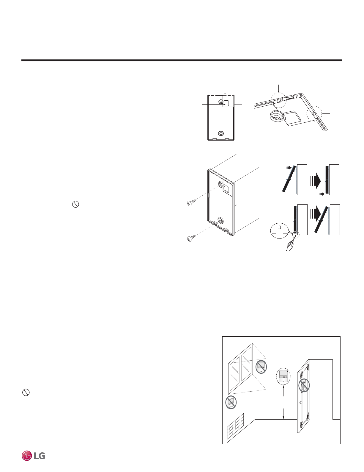
Installation and Best Layout Practices
DUCT (LOW STATIC) INDOOR UNITS
Figure 145:Removing the Cable Guide Grooves.
Hanging the Wired Controller
1. The controller wiring / cable can be installed in one of three direc-
tions: top, back, or on the right side. If top or right side installation
is desired, remove cable guide grooves on the controller, and
then position wiring / cable on applicable side.
2. Choose and mark the area of installation, and then screw the wall
plate into place (using the provided parts). Install the controller
wall plate to fit the electrical box if one is present. Ensure that no
gaps exist between the wall plate and the wall itself.
3. Arrange wiring / cables so as not to interfere with the controller
circuitry. Position the wired controller on the wall plate. Snap into
place by pressing the bottom part of the wired controller onto
the wall plate. Make sure that no gaps exist between the wired
controller and the wall plate on all sides.
4. To remove wired controller from the wall plate, insert a screw-
driver into the two holes at the bottom. Twist screwdriver to
release controller. Do not damage the controller components
when removing.
Back
Top
Top
Right
Side
Right
Side
Wall Wall
Wall Wall
Installing the Controller
Removing the Controller
Figure 146:Attaching the Wall Plate.
Figure 147: Installing / Removing
the Controller.
Assigning the Thermistor for Temperature Detection
Each indoor unit includes a return air thermistor assigned to sense the temperature. If a wired controller is installed, there is a choice of
sensing temperature with either the indoor unit return air thermistor or the thermistor in the wired controller. It is also an option to set both
thermistors to sense temperature so that indoor unit bases its operation on the first thermistor to reach the designated temperature differen-
tial. For applicable indoor units, an optional Remote Temperature Sensor can be used in lieu of the return air thermistor—either alone or in
conjunction with a wired controller thermistor as previously described.
4 to 5 feet
above the floor
NO
NO
NO
YES
Remote Controller
TEMP
Remote Controller
TEMP
Re
m
ot
e Co
nt
rol
l
er
TEMP
Wired Controller Placement
Wall indoor units can be used with various wired controllers (optional; sold sepa-
rately). Wired controllers include a sensor to detect room temperature. To maintain
comfort levels in the conditioned space, the wired controller must be installed in a
location away from direct sunlight, high humidity, and where it could be directly ex-
posed to cold air. Controller must be installed four (4) to five (5) feet above the floor
where its display can be read easily, in an area with good air circulation, and where it
can detect an average room temperature.
Do not install the remote controller where it can be impacted by the following:
• Drafts or dead spots behind doors and in corners
• Hot or cold air from ducts
• Radiant heat from sun or appliances
• Concealed pipes and chimneys
• Uncontrolled areas such as an outside wall behind the remote controller
Figure 148:Proper Location for the Wired Controller.
DUCT (LOW STATIC) | 113
Ceiling-Concealed Duct (Low Static)
Due to our policy of continuous product innovation, some specications may change without notication.
©LG Electronics U.S.A., Inc., Englewood Cliffs, NJ. All rights reserved. “LG” is a registered trademark of LG Corp.
MULTI
F
MAX
MULTI
F
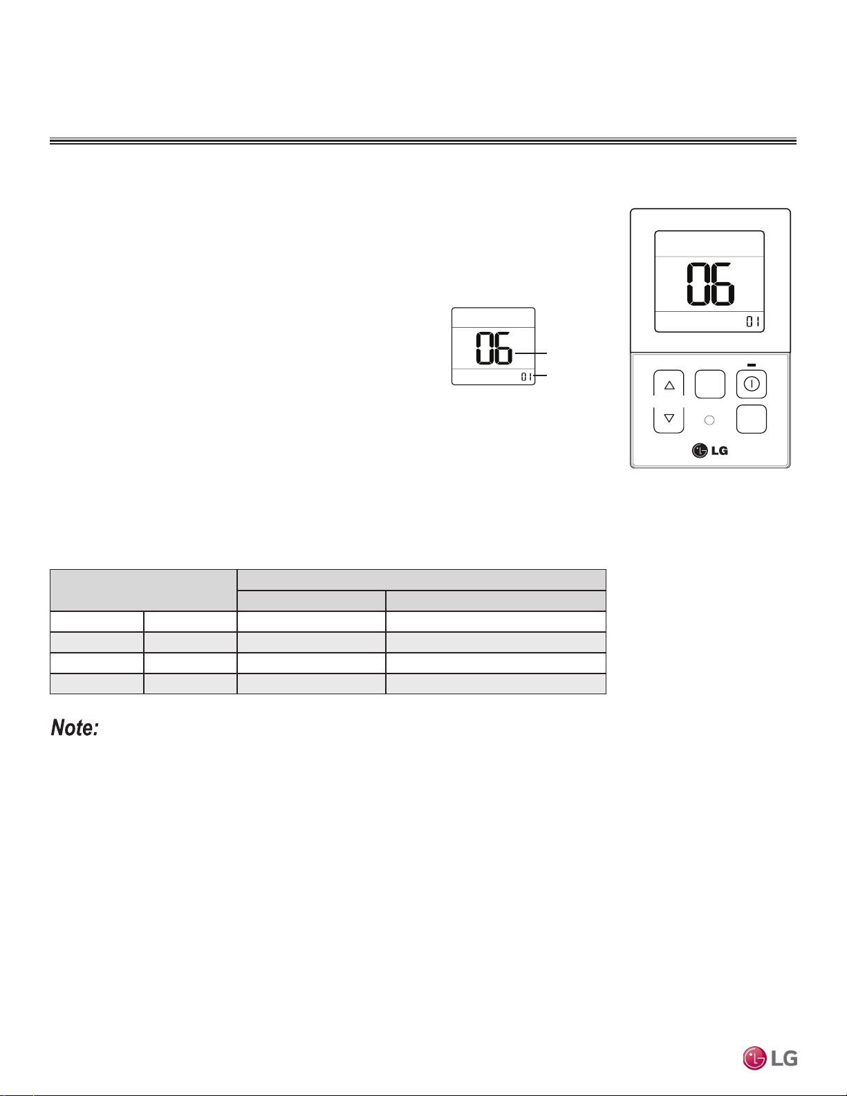
DUCT (LOW STATIC) INDOOR UNITS
Installation and Best Layout Practices
1. To access system installer setting mode, press and hold the temperature increase and mode selection
buttons simultaneously for approximately three (3) seconds. Choose setting code value “06” by press-
ing the mode selection button.
2. Use the temperature increase and decrease buttons to select the
desired setting value.
Setting Values
3. Press the on / off button to save the established settings.
4. To deactivate system installer setting mode after the settings have been established, press and hold
the temperature increase and mode selection check buttons simultaneously for approximately three
(3) seconds. If a button is not pressed for more than 25 seconds, the system installer setting mode
will automatically deactivate.
• Select the position after verifying duct work and the external static pressure of the indoor unit.
• Factory set to pressure selection F-H.
Table 56:Static Pressure Setting Table.
Pressure Selection
Function
Zone State External Static Pressure Standard Value
01 V-H Variable High
02 F-H Fixed High
03 V-L Variable Low
04 F-L Fixed Low
TEM P
FA N
SPEED
OPER
MODE
Code
Set Value
Figure 149:Select Code and
Set Value.
01 : V-H
02 : F-H
03 : V-L
04 : F-L
Figure 150:Controller External
Static Pressure Setting Display.
External Static Pressure Control
To provide a required air flow rate that accounts for the external static pressure change, follow the steps
below.
Due to our policy of continuous product innovation, some specications may change without notication.
©LG Electronics U.S.A., Inc., Englewood Cliffs, NJ. All rights reserved. “LG” is a registered trademark of LG Corp.
114 | DUCT (LOW STATIC)
Multi F and Multi F MAX Indoor Unit Engineering Manual
MULTI
F
MAX
MULTI
F
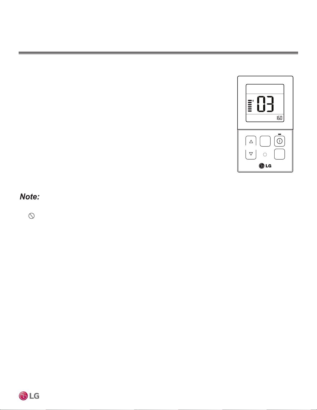
Installation and Best Layout Practices
DUCT (LOW STATIC) INDOOR UNITS
TEMP
FA N
SPEED
OPER
MODE
Figure 151:Controller External
Static Pressure Setting Display.
• A certified technician must set the external static pressure value(s). If the external static pressure is set incorrectly, the system will
malfunction.
•
Do not alter the external static pressure value that corresponds to each air flow level.
• External static pressure value can vary depending on the indoor unit.
• If by pressing the fan speed button during external static pressure setup, the fan speed is raised to the next level, the air flow value of
the previous fan speed will be maintained (external static pressure setting value is saved).
Assigning Air Flow
To assign an air flow for each fan speed, follow the steps below.
1. To access system installer setting mode, press and hold the temperature increase and mode selection
buttons simultaneously for approximately three (3) seconds. Choose setting code value “03” by press-
ing the mode selection button.
2. Use the fan speed button to select the desired fan speed. ( Lo→Med→Hi will display on the LED).
3. Use the temperature increase and decrease buttons to select the desired external static
pressure setting value (thereby assigning the respective airflow). External static pressure value range:
0~255; the value will display near the lower right corner of the LED.
4. Press the on / off button to save the established settings.
5. To deactivate system installer setting mode after the settings have been established, press and hold
the temperature increase and mode selection check buttons simultaneously for approximately three
(3) seconds. If a button is not pressed for more than 25 seconds, the system installer setting mode
will automatically deactivate.
DUCT (LOW STATIC) | 115
Ceiling-Concealed Duct (Low Static)
Due to our policy of continuous product innovation, some specications may change without notication.
©LG Electronics U.S.A., Inc., Englewood Cliffs, NJ. All rights reserved. “LG” is a registered trademark of LG Corp.
MULTI
F
MAX
MULTI
F

CEILING-CONCEALED
DUCT (HIGH STATIC)
INDOOR UNIT DATA
“Mechanical Specifications” on page 117
“General Data / Specifications” on page 118
“Dimensions” on page 119
“Cooling Capacity Table” on page 121
“Heating Capacity Table” on page 122
“External Static Pressure” on page 123
“Acoustic Data” on page 123
“Refrigerant Flow Diagrams” on page 124
“Wiring Diagram” on page 125
“Factory Supplied Parts and Materials” on page 126
“Installation and Best Layout Practices” on page 127
MULTI
F
MAX
MULTI
F
Mechanical Specications and Features
DUCT (HIGH STATIC) INDOOR UNITS
Ceiling-Concealed Duct (High Static)
Indoor Unit
General
All LG indoor units are factory assembled, wired, piped, and provided
with a control circuit board, fan, and motor. Ceiling-Concealed Duct
(High Static) units are designed for high-speed air volume against an
external static pressure up to 0.78″WG for the 24,000 Btu/h model;
up to 0.55″WG for the 36,000 Btu/h model.
Coil
Indoor unit coils are factory built and are comprised of aluminum fins
mechanically bonded to copper tubing. Each unit has two rows of
coils, which are pressure tested at the factory. Each unit is provided
with a factory installed condensate drain pan below the coil.
Refrigerant System
System is designed for use with R410A refrigerant. The refrigeration
circuit is pressure-tested at the factory and shipped with a holding
charge of helium gas. Refrigerant pipe connections are 45° flare,
and all refrigerant lines from the outdoor unit to the indoor units must
be field insulated.
Electrical
Each indoor unit is designed to operate using 208–230/60/1 power
with voltage variances of ±10%.
Casing
The casing is designed to mount fully concealed above a finished
ceiling. Casing is manufactured of galvanized steel plate. Cold sur-
faces of the unit are covered internally with a coated polystyrene in-
sulating material, and covered externally with sheet insulation made
of ethylene propylene diene monomer (M-Class) (EPDM). External
insulation is plenum rated and conforms to ASTM Standard D-1418.
Hanger brackets are included on the casing to support the weight on
four corners. Unit has a front horizontal supply air discharge outlet,
and one dedicated rear horizontal return air inlet.
Fan Assembly and Control
The 24MBH (LHN248HV) indoor unit has one direct-drive Sirocco
fan, while the 36MBH (LHN368HV) indoor unit has two direct-drive
Sirocco fans. The fans are made of high strength ABS GP-2200
polymeric resin that are statically and dynamically balanced. The
fans are mounted on a common brushless digitally controlled (BLDC)
motor with permanently lubricated and sealed ball bearings. The fan
/ motor assembly is mounted on vibration-attenuating rubber grom-
mets. Fan speed is controlled using a microprocessor-based direct
digital control algorithm. The indoor fan has Low, Med, High, and
Auto settings for Cooling mode; and has Low, Med, High, and Auto
settings for Heating mode. Each of the settings can be field-adjusted
from the factory setting (RPM / ESP). The Auto setting adjusts the
fan speed based on the difference between the controller setpoint
and space temperature.
Air Filter
Return air is filtered with a factory-supplied, removable, washable
filter accessible from the rear of the indoor unit. High efficiency air
filter options include a return filter box and an LG / Dynamic supplied
air cleaner (both sold separately).
Microprocessor Control
The unit is provided with an integrated control panel to communicate
with the outdoor unit. All unit operation parameters are stored in non-
volatile memory resident on the unit microprocessor. The micropro-
cessor controls space temperature through using the value provided
by the temperature sensor within the indoor unit. The microprocessor
control will activate indoor unit operation when the indoor room tem-
perature falls below or rises above a setpoint temperature, at which
point, a signal is sent to the outdoor unit to begin the appropriate
mode. The microprocessor will also provide self-diagnostics and auto
restart functions. A field-supplied four-wire power / communications
cable must be installed to connect the indoor unit(s) to the outdoor
unit.
Controls
The indoor unit controller of choice must be ordered separately.
Communication between the indoor units and the outdoor unit is ac-
complished through 14 AWG, four-core, stranded and shielded power
/ communication cable.
Condensate Lift/Pump
The indoor unit is provided with a factory installed and wired internal
condensate lift/pump capable of providing a minimum 27.5 inch lift
from the bottom surface of the unit. Drain pump has a safety switch
to shut off the indoor unit if the condensate rises too high in the drain
pan.
• Inverter (Variable speed fan)
• Internal drain pump
• Control lock function
• Auto operation
• Auto restart operation
• Dehumidifying function
• Two thermistor control
• External static pressure control
• Group control
• Self-diagnostics function
• Wired controller ordered separately
• Wi-Fi compatible
Features
Figure 152: Ceiling-Concealed Duct (High Static) Indoor Unit.
DUCT (HIGH STATIC) | 117
Ceiling-Concealed Duct (High Static)
Due to our policy of continuous product innovation, some specications may change without notication.
©LG Electronics U.S.A., Inc., Englewood Cliffs, NJ. All rights reserved. “LG” is a registered trademark of LG Corp.
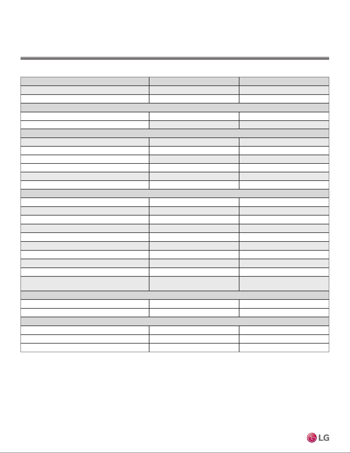
MULTI
F
MAX
MULTI
F
Model Name LHN248HV LHN368HV
Nominal Cooling Capacity (Btu/h)
1
24,000 36,000
Nominal Heating Capacity (Btu/h)
1
27,000 40,000
Operating Range
Cooling (°F WB)
57-77 57-77
Heating (°F DB)
59-81 59-81
Fan
Type
Sirocco Sirocco
Motor Output (W) x Qty.
136.5 x 1 259 x 1
Motor/Drive
Brushless Digitally Controlled / Direct Brushless Digitally Controlled / Direct
Factory Set Airflow Rate CFM (H/M/L)
777 / 706 / 636 1,130 / 989 / 848
Factory Set External Static Pressure (in. wg)
0.24 0.24
Maximum External Static Pressure (in. wg)
0.59 0.59
Unit Data
Refrigerant Type
2
R410A R410A
Refrigerant Control
EEV EEV
Power Supply V, Ø, Hz
3
208-230, 1, 60 208-230, 1, 60
Rated Amps (A)
1.6 2.3
Sound Pressure Level (Standard Mode) dB(A) H/M/L)
4
37 / 35 / 34 44 / 42 / 40
Dimensions (W x H x D, in.)
35-7/16 x 10-5/8 x 27-9/16 49-3/16 x 10-5/8 x 27-9/16
Net Unit Weight (lbs.)
58.6 85.3
Shipping Weight (lbs.)
71.9 99.4
Power Wiring / Communications Cable (No. x AWG)
5
4 x 14 4 x 14
Heat Exchanger
(Row x Column x Fin / inch) x Number
(3 x 13 x 18) x 1 (3 x 13 x 18) x 1
Pipe Size
Liquid (in.)
1/4 3/8
Vapor (in.)
1/2 5/8
Connection Size
Liquid (in.)
3/8 3/8
Vapor (in.)
5/8 5/8
Drain O.D. / I.D. (in.)
1-1/4, 1 1-1/4, 1
Table 57: Multi F Ceiling-Concealed High-Static Ducted Indoor Unit General Data.
DUCT (HIGH STATIC) INDOOR UNITS
General Data / Specications
1
Nominal capacity is rated 0 ft. above sea level with corresponding refrigerant piping length in
accordance with standard length of each outdoor unit and a 0 ft. level difference between outdoor and
indoor units. All capacities are net with a combination ratio between 95 – 105%.
Nominal cooling capacity rating obtained with air entering the indoor unit at 80ºF dry bulb (DB) and 67ºF
wet bulb (WB) and outdoor ambient conditions of 95ºF dry bulb (DB) and 75ºF wet bulb (WB).
Nominal heating capacity rating obtained with air entering the indoor unit at 70ºF dry bulb (DB) and 60ºF
wet bulb (WB) and outdoor ambient conditions of 47ºF dry bulb (DB) and 43ºF wet bulb (WB).
2
This unit comes with a dry helium charge.
3
Acceptable operating voltage: 187V-253V.
4
Sound pressure levels are tested in an anechoic chamber under ISO Standard 3745 and are the
same in both cooling and heating mode. These values can increase due to ambient conditions during
operation.
5
All power wiring / communications cable to the IDUs be minimum 14 AWG, 4-conductor, stranded,
shielded or unshielded (if shielded, must be grounded to chassis at ODU only) and must comply with
applicable local and national codes.
Due to our policy of continuous product innovation, some specications may change without notication.
©LG Electronics U.S.A., Inc., Englewood Cliffs, NJ. All rights reserved. “LG” is a registered trademark of LG Corp.
118 | DUCT (HIGH STATIC)
Multi F and Multi F MAX Indoor Unit Engineering Manual
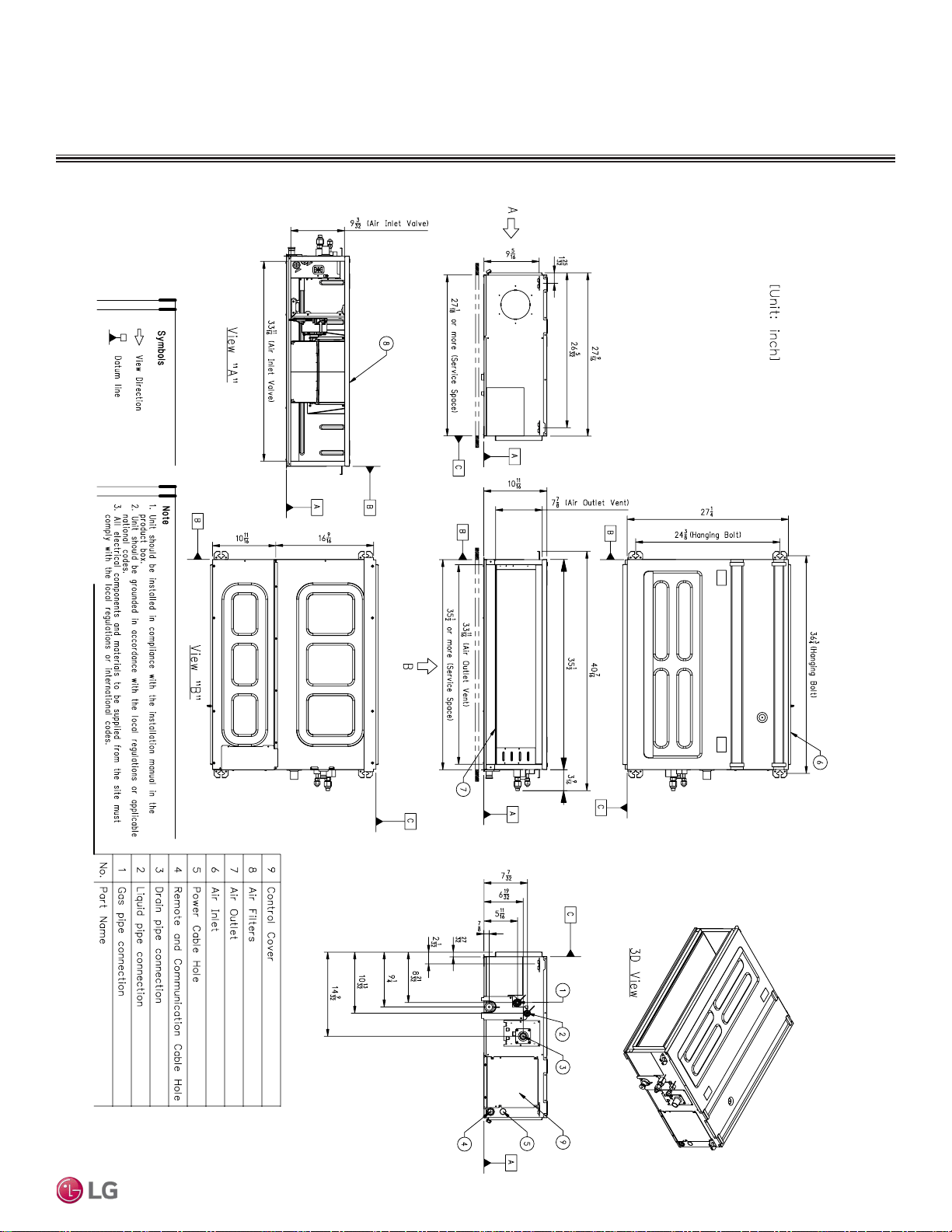
MULTI
F
MAX
MULTI
F
Dimensions
Figure 153: LHN248HV Dimensions.
DUCT (HIGH STATIC) INDOOR UNITS
DUCT (HIGH STATIC) | 119
Ceiling-Concealed Duct (High Static)
Due to our policy of continuous product innovation, some specications may change without notication.
©LG Electronics U.S.A., Inc., Englewood Cliffs, NJ. All rights reserved. “LG” is a registered trademark of LG Corp.
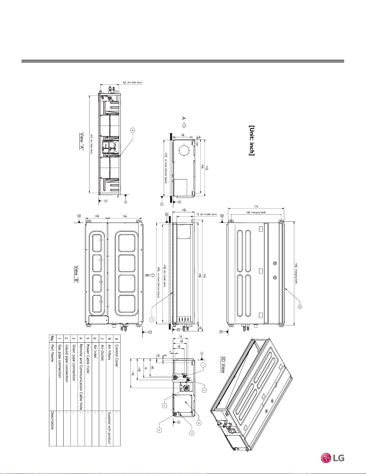
MULTI
F
MAX
MULTI
F
Figure 154: LHN368HV Dimensions.
Due to our policy of continuous product innovation, some specications may change without notication.
©LG Electronics U.S.A., Inc., Englewood Cliffs, NJ. All rights reserved. “LG” is a registered trademark of LG Corp.
120 | DUCT (HIGH STATIC)
Multi F and Multi F MAX Indoor Unit Engineering Manual

MULTI
F
MAX
MULTI
F
DUCT (HIGH STATIC) INDOOR UNITS
Cooling Capacity Table
Table 58:Multi F Ceiling-Concealed Duct (High Static) Indoor Units Cooling Capacity Table.
TC = Total Capacity (kBtu/h).
SHC: Sensible Heat Capacity (kBtu/h).
Nominal capacity as rated 0 ft. above sea level and a 0 ft. level difference between outdoor and indoor units. Corresponding refrigerant piping length is accordance with standard length of each outdoor unit.
Nominal cooling capacity rating obtained with air entering the indoor unit at 80ºF dry bulb (DB) and 67ºF wet bulb (WB), and outdoor ambient conditions of 95ºF dry bulb (DB) and 75ºF wet bulb (WB).
The shaded table columns and rows indicate reference data. When operating at this temperature, these values can be different if the system is not running consistently.
Model No. /
Nominal Capacity
of Indoor Unit
(Btu/h)
Outdoor Air
Temp.
(°F DB)
Indoor Air Temp. °F DB / °F WB
68 / 57 73 / 61 77 / 64 80 / 67 86 / 72 90 / 75
TC SHC TC SHC TC SHC TC SHC TC SHC TC SHC
LHN248HV
24,000
14 23.53 17.66 24.99 18.66 26.45 18.07 27.50 18.45 29.37 18.60 30.83 18.95
20 23.51 17.80 24.97 18.80 26.43 18.21 27.48 18.59 29.35 18.75 30.81 19.10
25 23.49 17.94 24.95 18.95 26.41 18.35 27.46 18.73 29.33 18.89 30.79 19.25
30 23.47 18.08 24.93 19.09 26.39 18.49 27.44 18.88 29.30 19.04 30.76 19.40
35 23.46 18.21 24.91 19.24 26.37 18.63 27.42 19.02 29.28 19.18 30.74 19.54
40 23.44 18.35 24.89 19.38 26.35 18.77 27.40 19.16 29.26 19.33 30.72 19.69
45 23.42 18.49 24.87 19.53 26.33 18.91 27.38 19.31 29.24 19.47 30.69 19.84
50 23.40 18.62 24.85 19.67 26.31 19.05 27.36 19.45 29.21 19.61 30.67 19.99
55 23.38 18.76 24.84 19.82 26.29 19.19 27.34 19.59 29.19 19.76 30.64 20.13
60 23.37 18.90 24.82 19.96 26.27 19.33 27.32 19.73 29.17 19.90 30.62 20.28
65 23.35 19.03 24.80 20.10 26.25 19.47 27.29 19.88 29.15 20.04 30.60 20.42
70 23.33 19.17 24.78 20.25 26.23 19.61 27.27 20.02 29.13 20.19 30.57 20.57
75 22.77 18.85 24.21 19.94 25.66 19.33 26.70 19.75 28.55 19.94 29.99 20.34
80 22.21 18.53 23.65 19.63 25.09 19.05 26.13 19.48 27.97 19.69 29.42 20.10
85 21.65 18.19 23.09 19.30 24.53 18.75 25.57 19.19 27.40 19.43 28.84 19.84
90 21.09 17.85 22.53 18.96 23.96 18.45 25.00 18.90 26.83 19.15 28.27 19.59
95 20.49 17.66 21.92 18.79 23.35 18.31 24.00 18.48 26.20 19.05 27.63 19.50
100 19.99 17.19 21.42 18.31 22.85 17.87 23.69 18.19 25.70 18.64 27.13 19.10
105 19.49 16.71 20.92 17.84 22.35 17.43 23.38 17.91 25.20 18.23 26.63 18.70
110 18.99 16.14 20.42 17.26 21.85 16.90 22.88 17.37 24.70 17.71 26.13 18.19
115 18.49 15.66 19.92 16.78 21.35 16.45 22.38 16.93 24.20 17.29 25.63 17.77
118 18.19 15.55 19.62 16.68 21.05 16.36 22.08 16.86 23.90 17.23 25.33 17.72
122 18.10 15.51 19.52 16.64 20.95 16.34 21.98 16.83 23.81 17.21 25.23 17.71
LHN368HV
36,000
14 35.29 25.46 37.48 26.90 39.67 26.04 41.26 26.59 44.06 26.81 46.25 27.32
20 35.26 25.66 37.45 27.11 39.64 26.25 41.23 26.80 44.02 27.02 46.21 27.54
25 35.24 25.86 37.43 27.32 39.61 26.45 41.19 27.01 43.99 27.23 46.18 27.75
30 35.21 26.06 37.40 27.53 39.58 26.65 41.16 27.21 43.96 27.44 46.14 27.96
35 35.18 26.25 37.37 27.73 39.55 26.85 41.13 27.42 43.92 27.65 46.11 28.17
40 35.16 26.45 37.34 27.94 39.52 27.06 41.10 27.63 43.89 27.86 46.07 28.39
45 35.13 26.65 37.31 28.15 39.49 27.26 41.07 27.83 43.86 28.07 46.04 28.60
50 35.10 26.85 37.28 28.36 39.46 27.46 41.04 28.04 43.82 28.27 46.00 28.81
55 35.08 27.04 37.25 28.57 39.43 27.66 41.01 28.24 43.79 28.48 45.97 29.02
60 35.05 27.24 37.23 28.78 39.40 27.86 40.97 28.45 43.76 28.69 45.93 29.23
65 35.02 27.44 37.20 28.98 39.37 28.06 40.94 28.65 43.72 28.90 45.90 29.44
70 34.99 27.63 37.17 29.19 39.34 28.26 40.91 28.86 43.69 29.10 45.86 29.65
75 34.15 27.18 36.32 28.75 38.49 27.87 40.05 28.47 42.82 28.75 44.99 29.32
80 33.31 26.71 35.47 28.29 37.64 27.46 39.20 28.08 41.96 28.39 44.12 28.97
85 32.48 26.23 34.63 27.82 36.79 27.03 38.35 27.66 41.10 28.00 43.26 28.61
90 31.64 25.73 33.79 27.33 35.94 26.59 37.50 27.24 40.25 27.61 42.40 28.23
95 30.74 25.46 32.88 27.09 35.02 26.39 36.00 26.64 39.30 27.46 41.44 28.11
100 29.99 24.78 32.13 26.40 34.27 25.76 35.53 26.23 38.55 26.87 40.69 27.53
105 29.24 24.10 31.38 25.72 33.52 25.13 35.07 25.82 37.80 26.28 39.94 26.96
110 28.49 23.27 30.63 24.89 32.77 24.36 34.32 25.04 37.05 25.54 39.20 26.22
115 27.74 22.58 29.88 24.19 32.02 23.71 33.57 24.41 36.31 24.93 38.45 25.62
118 27.29 22.41 29.43 24.04 31.57 23.59 33.12 24.30 35.86 24.84 38.00 25.55
122 27.14 22.36 29.28 23.99 31.43 23.55 32.97 24.26 35.71 24.81 37.85 25.53
DUCT (HIGH STATIC) | 121
Ceiling-Concealed Duct (High Static)
Due to our policy of continuous product innovation, some specications may change without notication.
©LG Electronics U.S.A., Inc., Englewood Cliffs, NJ. All rights reserved. “LG” is a registered trademark of LG Corp.
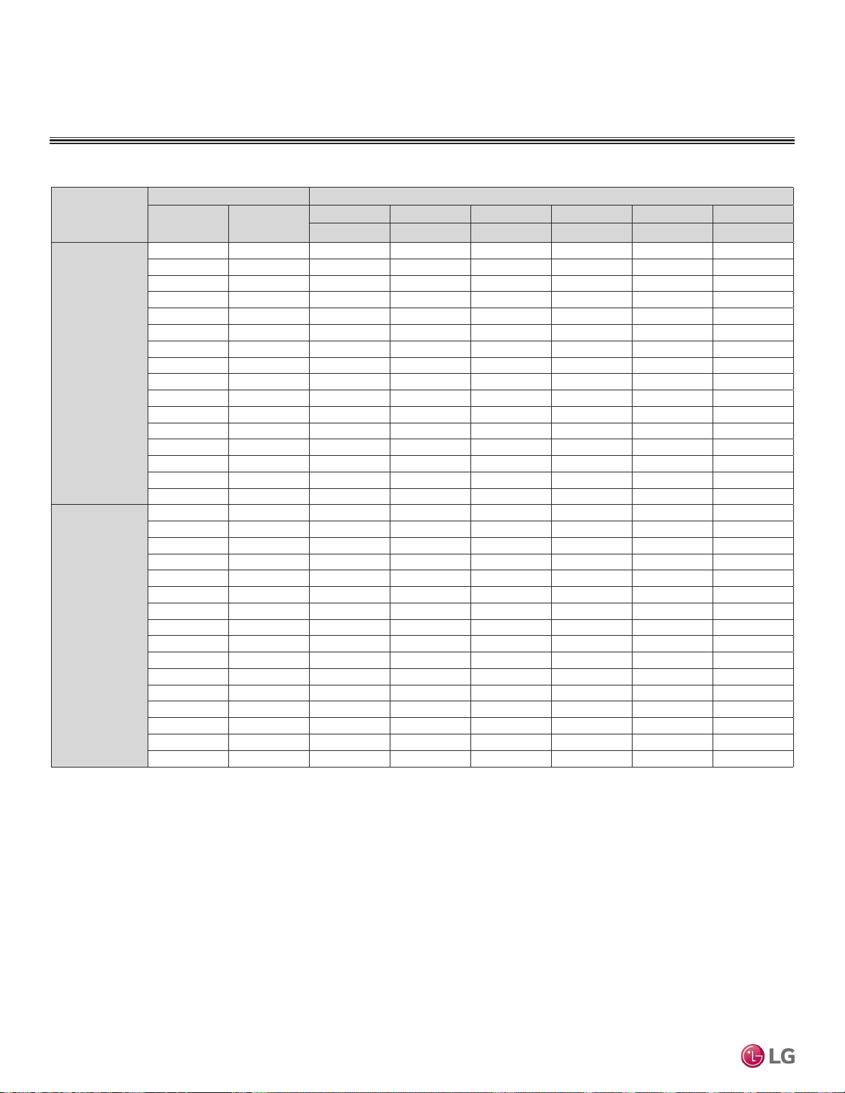
MULTI
F
MAX
MULTI
F
Table 59:Multi F Ceiling-Concealed Duct (High Static) Indoor Units Heating Capacity Table.
Model No. /
Nominal Capacity
of Indoor Unit
(Btu/h)
Outdoor Air Temp. Indoor Air Temp. °F DB
°F DB °F WB
61 64 68 70 72 75
TC TC TC TC TC TC
LHN248HV
24,000
0 -0.4 13.89 13.70 13.57 13.50 13.30 12.72
5 4.5 15.65 15.46 15.33 15.26 15.07 14.48
10 9 17.41 17.22 17.09 17.02 16.83 16.24
17 15 19.76 19.57 19.43 19.37 19.17 18.55
20 19 20.64 20.45 20.32 20.25 20.05 19.37
25 23 22.11 21.91 21.78 21.72 21.52 20.74
30 28 23.38 23.18 23.05 22.99 22.79 22.11
35 32 24.65 24.46 24.33 24.26 24.07 23.48
40 36 25.79 25.60 25.47 25.40 25.21 24.62
45 41 26.93 26.74 26.61 26.54 26.35 25.76
47 43 27.39 27.20 27.07 27.00 26.80 26.22
50 46 27.83 27.64 27.51 27.44 27.24 26.58
55 51 28.57 28.37 28.24 28.17 27.98 27.20
60 56 28.57 28.37 28.24 28.17 27.98 27.32
63 59 28.57 28.37 28.24 28.17 27.98 27.39
68 64 28.57 28.37 28.24 28.17 27.98 27.51
LHN368HV
36,000
0 -0.4 20.58 20.29 20.10 20.00 19.71 18.84
5 4.5 23.19 22.90 22.71 22.61 22.32 21.45
10 9 25.80 25.51 25.31 25.22 24.93 24.06
17 15 29.28 28.99 28.79 28.70 28.41 27.48
20 19 30.58 30.29 30.10 30.00 29.71 28.70
25 23 32.75 32.46 32.27 32.17 31.88 30.72
30 28 34.64 34.35 34.15 34.06 33.77 32.75
35 32 36.52 36.23 36.04 35.94 35.65 34.78
40 36 38.21 37.92 37.73 37.63 37.34 36.47
45 41 39.90 39.61 39.42 39.32 39.03 38.16
47 43 40.58 40.29 40.10 40.00 39.71 38.84
50 46 41.23 40.94 40.75 40.65 40.36 39.38
55 51 42.32 42.03 41.84 41.74 41.45 40.29
60 56 42.32 42.03 41.84 41.74 41.45 40.47
63 59 42.32 42.03 41.84 41.74 41.45 40.58
68 64 42.32 42.03 41.84 41.74 41.45 40.76
Heating Capacity Table
DUCT (HIGH STATIC) INDOOR UNITS
TC = Total Capacity (kBtu/h).
Nominal capacity as rated 0 ft. above sea level and a 0 ft. level difference between outdoor and indoor units. Corresponding refrigerant piping length is accordance with standard length of each outdoor unit.
Nominal heating capacity rating obtained with air entering the indoor unit at 70ºF dry bulb (DB) and 60ºF wet bulb (WB), and outdoor ambient conditions of 47ºF dry bulb (DB) and 43ºF wet bulb (WB).
Due to our policy of continuous product innovation, some specications may change without notication.
©LG Electronics U.S.A., Inc., Englewood Cliffs, NJ. All rights reserved. “LG” is a registered trademark of LG Corp.
122 | DUCT (HIGH STATIC)
Multi F and Multi F MAX Indoor Unit Engineering Manual
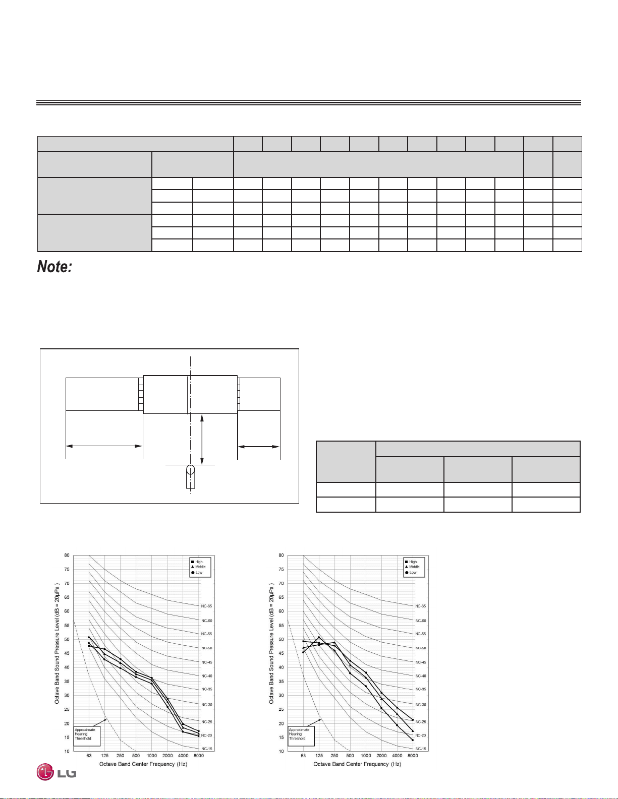
MULTI
F
MAX
MULTI
F
DUCT (HIGH STATIC) INDOOR UNITS
External Static Pressure / Acoustic Data
Static Pressure (in. wg) 0.1 0.16 0.2 0.24 0.28 0.31 0.35 0.39 0.43 0.47 0.51 0.59
Model No. / Nominal Capacity
of Indoor Unit (Btu/h)
Airflow Rate / CFM Setting Value (in. wg)
LHN248HV
24,000
High 777 110 117 121 124 127 130 133 136 137 - 138 140
Mid 706 102 110 114 118 120 125 127 130 133 - 134 136
Low 636 96 102 107 110 114 118 122 125 127 - 130 132
LHN368HV
36,000
High 1,130 - 109 112 115 119 122 126 128 131 134 137 144
Mid 989 - 101 105 108 112 115 119 123 127 130 133 138
Low 848 - 92 97 101 105 109 113 117 121 124 127 134
Table 61:Sound Pressure Levels (dB[A]).
• To get the desired air flow and external static pressure combination, use the setting value from the table. Using a setting value other
than that listed in the table will not provide the desired combination.
• Table data is based at 230V. Air flow rate varies according to voltage fluctuation.
Model No.
Sound Pressure Levels (dB[A]) (Cooling and Heating)
High Fan Speed
Medium Fan
Speed
Low Fan Speed
LHN248HV 37 35 34
LHN368HV 44 42 40
Figure 155: Sound Pressure Level Measurement Location.
Table 60:Multi F Ceiling-Concealed Duct (High Static) External Static Pressure Setting Values Table.
Figure 156: Sound Pressure Level Diagrams.
• Measurements taken with no attenuation and units operating at full
load normal operating condition.
• Sound level will vary depending on a range of factors such as
construction (acoustic absorption coefficient) of particular area in
which the equipment is installed.
• Sound power levels are measured in dB(A).
• Tested in anechoic chamber per ISO Standard 3745.
4.9 ft.
6.6 ft.
3.3 ft.
DUCT
DISCHARGE SUCTION
DUCT
LHN248HV LHN368HV
DUCT (HIGH STATIC) | 123
Ceiling-Concealed Duct (High Static)
Due to our policy of continuous product innovation, some specications may change without notication.
©LG Electronics U.S.A., Inc., Englewood Cliffs, NJ. All rights reserved. “LG” is a registered trademark of LG Corp.
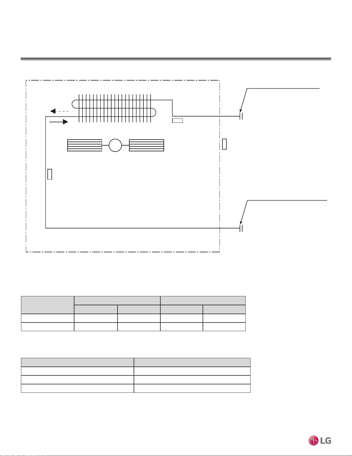
MULTI
F
MAX
MULTI
F
Refrigerant Flow Diagrams
Figure 157: LHN248HV and LHN368HV Refrigerant Flow Diagram.
Table 62: Multi F Ceiling-Concealed Duct (High Static) IDU Refrigerant Piping and Connection Sizes.
Table 63: Multi F Ceiling-Concealed Duct (High Static) Indoor Unit Thermistor Details.
Description (Based on Cooling Mode) PCB Connector
Indoor Air Temperature Thermistor CN-ROOM
Evaporator Inlet Temperature Thermistor CN-PIPE/IN
Evaporator Outlet Temperature Thermistor CN-PIPE/OUT
Sirocco Fan
Heat exchanger
Gas pipe connection port
(flare connection)
Liquid pipe connection port
(flare connection)
Cooling
Heating
M
Thermistor for
suction air
temperature
Thermistor for
evaporator outlet
temperature
Thermistor for
evaporator inlet
temperature
DUCT (HIGH STATIC) INDOOR UNITS
Model No.
Piping Size Connection Port Size
Liquid (inch) Vapor (inch) Liquid (inch) Vapor (inch)
LHN248HV 1/4 1/2 3/8 5/8
LHN368HV 3/8 5/8 3/8 5/8
Due to our policy of continuous product innovation, some specications may change without notication.
©LG Electronics U.S.A., Inc., Englewood Cliffs, NJ. All rights reserved. “LG” is a registered trademark of LG Corp.
124 | DUCT (HIGH STATIC)
Multi F and Multi F MAX Indoor Unit Engineering Manual
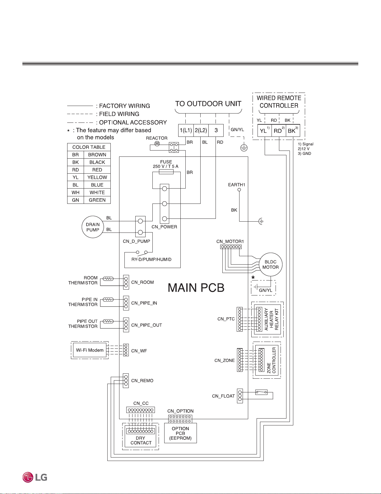
MULTI
F
MAX
MULTI
F
Wiring Diagrams
DUCT (HIGH STATIC) INDOOR UNITS
Figure 158: Multi F Ceiling-Concealed Duct (High Static) LHN248HV and LHN368HV Indoor Units Wiring Diagram.
DUCT (HIGH STATIC) | 125
Ceiling-Concealed Duct (High Static)
Due to our policy of continuous product innovation, some specications may change without notication.
©LG Electronics U.S.A., Inc., Englewood Cliffs, NJ. All rights reserved. “LG” is a registered trademark of LG Corp.
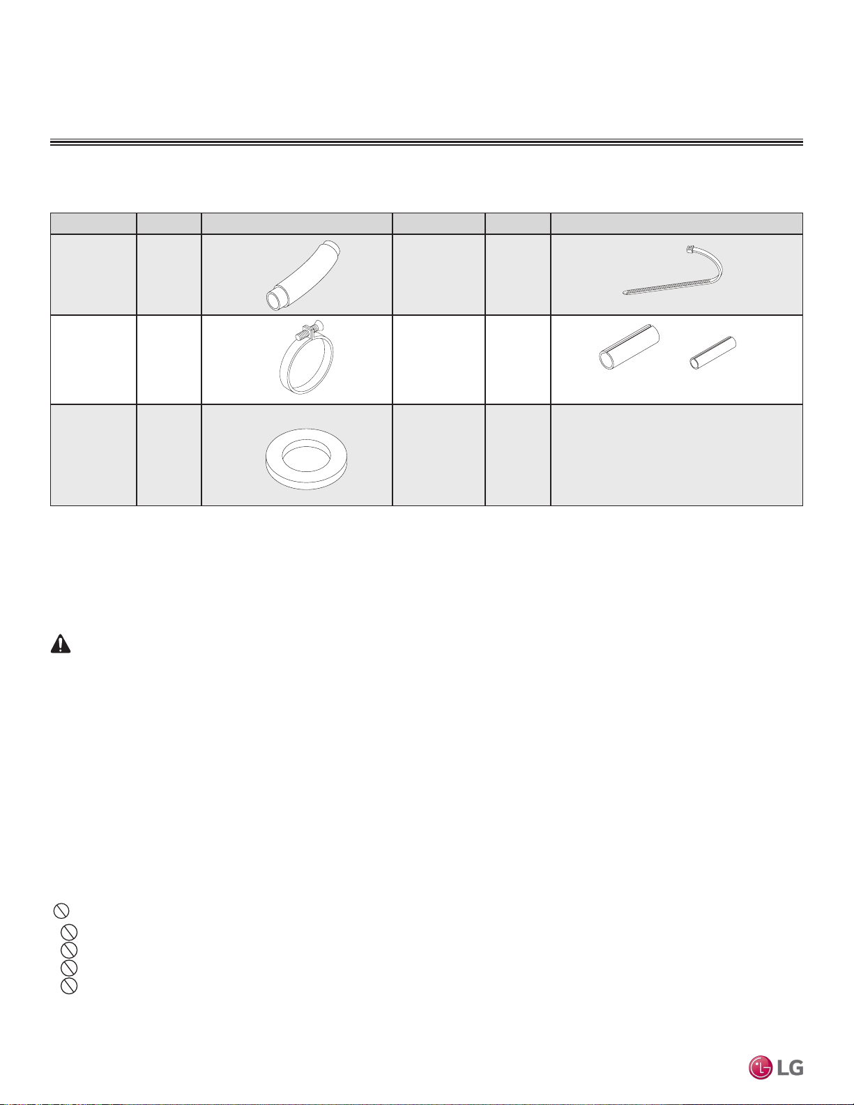
MULTI
F
MAX
MULTI
F
DUCT (HIGH STATIC) INDOOR UNITS
Factory Supplied Parts and Materials / Installation
Factory Supplied Materials
• Owner’s Manual
• Installation Manual
Selecting the Best Location
Do’s
• Place the unit where air circulation will not be blocked.
• Place the unit where drainage can be obtained easily.
• Place the unit where noise prevention is taken into consideration.
• Ensure there is sufcient strength to bear the load of the indoor unit.
• Ensure there is sufficient maintenance space.
• Locate the indoor unit in a location that is level, and where it can be easily connected to the outdoor unit / branch distribution unit.
Required Tools
• Level
• Screwdriver
• Electric drill
• Hole core drill
• Flaring tool set
• Torque wrenches
• Hexagonal wrench
• Gas-leak detector
• Thermometer
Factory Supplied Parts
Part Quantity Image Part Quantity Image
Drain Hose One (1) Zip Ties Four (4)
Metal Clamp Two (2)
Insulation for
Fittings
One (1) Set
Washers for
Hanging
Brackets
Eight (8)
Table 64: Parts Table.
For Vapor Piping For Liquid Piping
WARNING
Installation work must be performed by trained personnel and in accordance with national wiring standards and
all local or other applicable codes. Improper installation can result in re, electric shock, physical injury, or death.
Note:
Read all instructions before installing this product. Become familiar with the unit’s components and connections,
and the order of installation. Incorrect installation can degrade or prevent proper operation.
Don’ts
• Do not install the unit near a heat or steam source, or where considerable amounts of oil, iron powder, or flour are used.
• Do not install the unit where sulfuric acid and flammable or corrosive gases are generated, vented into, or stored.
•
Do not install the unit near high-frequency generators.
• Do not install the unit near a doorway.
The unit will be damaged, will malfunction, and / or will not operate as designed if installed in any of the conditions listed.
Due to our policy of continuous product innovation, some specications may change without notication.
©LG Electronics U.S.A., Inc., Englewood Cliffs, NJ. All rights reserved. “LG” is a registered trademark of LG Corp.
126 | DUCT (HIGH STATIC)
Multi F and Multi F MAX Indoor Unit Engineering Manual
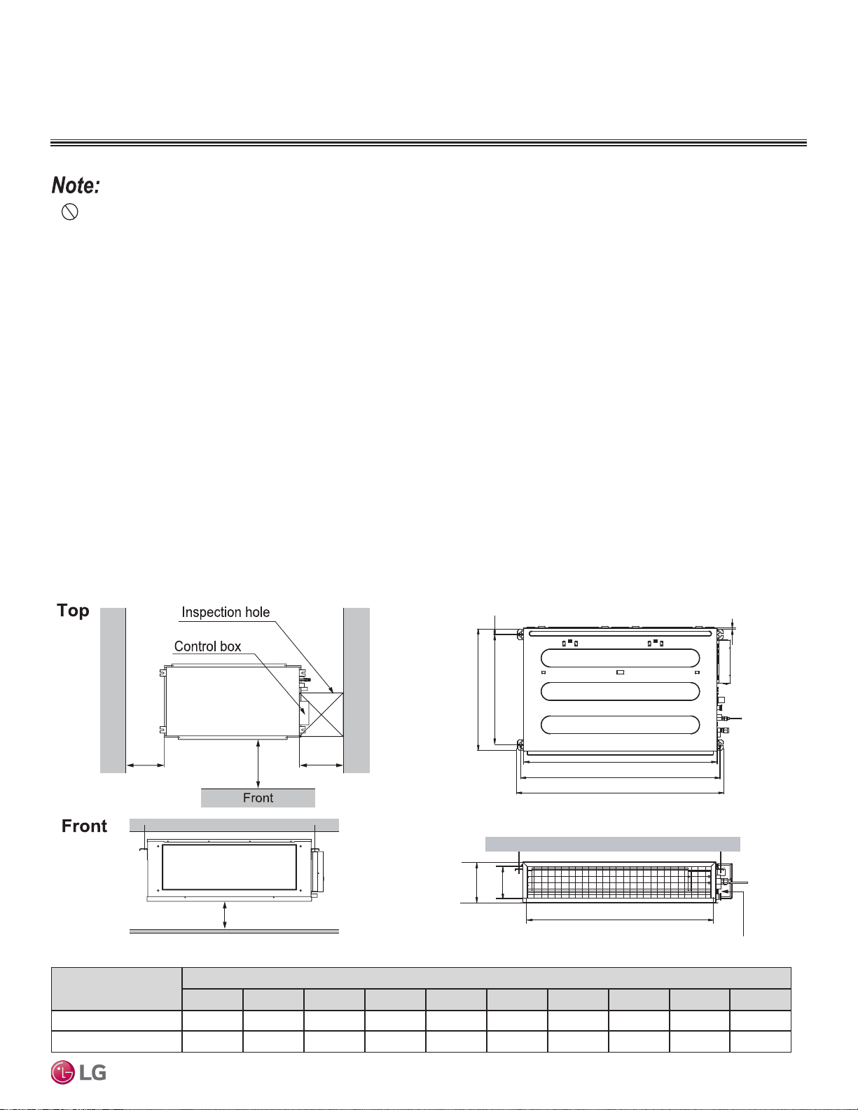
MULTI
F
MAX
MULTI
F
Installation and Best Layout Practices
DUCT (HIGH STATIC) INDOOR UNITS
Installing in an Area Exposed to Unconditioned Air
In some installation applications, areas (floors, walls) in some rooms will be exposed to unconditioned air (room will be above or next to an
unheated garage or storeroom). To countermeasure:
• Verify that carpet is or will be installed (carpet will increase the temperature by three degrees).
• Add insulation between the floor joists.
• Install radiant heat or another type of heating system to the floor.
Installing in an Area with High Humidity Levels
If the environment is prone to humidity levels of 80% or more (near the ocean, lakes, etc.) or where steam could collect in the plenum:
• Install additional insulation to the indoor unit (glass wool insulation >13/32 inches thick).
• Install additional insulation to the refrigerant piping (insulation >13/16 inches thick).
• Seal all gaps between the indoor unit and the ceiling tiles (make the area air tight) so that humidity does not transfer from the plenum to the
conditioned space. Also, add a ceiling grille for ventilation.
Figure 159: Access Panel and General Service Space Required
Dimensions.
Figure 160: Indoor Unit Bolt Locations.
23-5/8 inches x 23-5/8 inches
23-5/8
inches
39-3/8
inches
H = ≥25/32 inches
23-5/8
inches
Model / Capacity
(Btu/h)
Dimensions (inches)
A B C D E F G H I J
LHN248HV / 24,000 36-3/4 38-1/4 24-3/8 27-9/16 1-3/16 10-5/8 19/32 33-25/32 7-15/16 35-7/16
LHN368HV / 36,000 50-17/32 52-1/32 24-3/8 27-9/16 1-3/16 10-5/8 19/32 47-9/16 7-15/16 49-7/32
Table 65:Indoor Unit Bolt Location Dimensions.
• Indoor units (IDUs) must not be placed in an environment where the IDUs will be exposed to harmful volatile organic compounds (VOCs)
or in environments where there is improper air make up or supply or inadequate ventilation. If there are concerns about VOCs in the envi-
ronment where the IDUs are installed, proper air make up or supply and/or adequate ventilation must be provided. Additionally, in buildings
where IDUs will be exposed to VOCs, consider a third party factory-applied epoxy coating to the fan coils for each IDU where the entire coil
is dipped, not sprayed.
• If the unit is installed near a body of water, the installation parts are at risk of corroding. Appropriate anti-corrosion methods must be taken for
the unit and all installation parts.
C
E
G
D
F
I
A
J
B
H
Drainage hole
DUCT (HIGH STATIC) | 127
Ceiling-Concealed Duct (High Static)
Due to our policy of continuous product innovation, some specications may change without notication.
©LG Electronics U.S.A., Inc., Englewood Cliffs, NJ. All rights reserved. “LG” is a registered trademark of LG Corp.
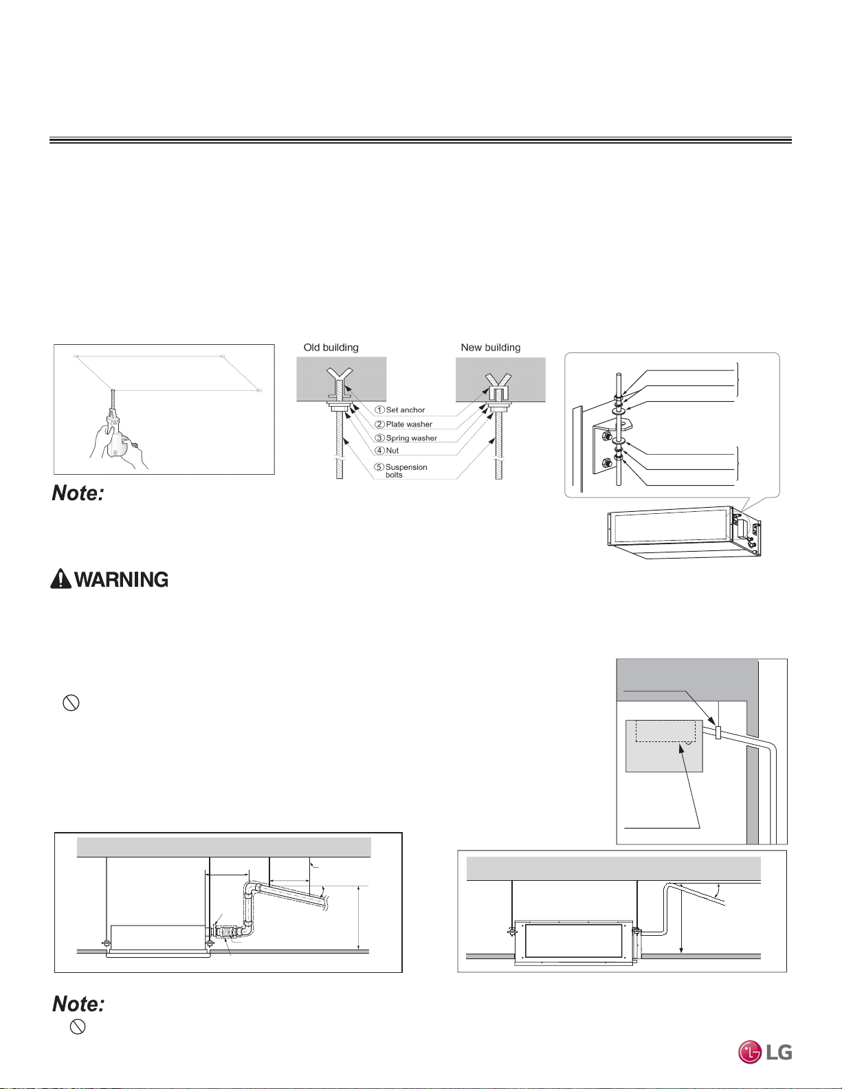
MULTI
F
MAX
MULTI
F
1. Select and mark the area for the suspension or console bolts (use
embedded inserts or anchor bolts in new buildings, and hole-in-
anchors in older buildings).
2. Drill the holes.
3. Add the set-anchor and the plate washer to the bolts (bolts must
be at least 13/32 inches in diameter), and then insert the bolts
into the installation area.
4. Add the plate washer, spring washer, and nut to secure the bolts
into the installation area.
5. Position the indoor unit installation plates onto the bolts. Secure
using nuts, plate washers, and spring washers. Adjust for level as
necessary.
• Unit must be installed correctly. Tighten the nuts and bolts to prevent the unit from falling and
causing severe injury or death.
Figure 161: Preparing the Installation Area.
Install a canvas duct to the air outlet and air inlet so that vibration from the indoor unit does not
carry to the duct or ceiling. Also, add insulation to the interior of the duct, and apply anti-vibration
to the suspension bolts.
Preparing the Installation Area and Hanging the Indoor Unit Frame
Figure 162: Suspension Bolt Options.
Figure 163: Hanging the Indoor Unit.
M10 Nut
M10 SP. washer
M10 washer
X 4
X 4
(Field-
supplied)
X 4
M10 Nut
M10 SP. washer
M10 washer
X 4
X 4
X 4
(Field-
supplied)
Do not apply force or twist the drain hose: it will leak.
1/50~1/100 slope
Hanger distance
3.3~49.2 feet
Hanger Bracket
Maximum
27-9/16 inches
Flexible drain hose
Insulation
Metal
clamp
Maximum
11-13/16 inches
Installing the Drain System
• Drain piping must have downward gradient of at least 1/50 to 1/100; to prevent reverse flow, slope must
not be straight up and down.
• Do not damage the drain port on the indoor unit when connecting the field-supplied drain piping.
• Drain piping specifications:
- Indoor Unit Drain Connection: 1-1/4 inch outside diameter.
- Field-Supplied Drain Piping: Polyvinyl chloride piping with 1-inch inside diameter and pipe fittings.
Drain Port
Maintenance
Drain Pipe Support
Indoor unit
1/50~1/100mm
Maximum
27-9/16 inches
Figure 164:Indoor Unit Drain Piping.
Figure 165:Drain Piping Installation Dimensions.
Installation and Best Layout Practices
DUCT (HIGH STATIC) INDOOR UNITS
Due to our policy of continuous product innovation, some specications may change without notication.
©LG Electronics U.S.A., Inc., Englewood Cliffs, NJ. All rights reserved. “LG” is a registered trademark of LG Corp.
128 | DUCT (HIGH STATIC)
Multi F and Multi F MAX Indoor Unit Engineering Manual
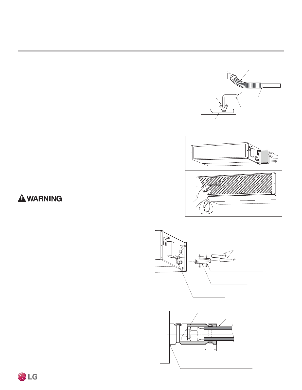
MULTI
F
MAX
MULTI
F
Installation and Best Layout Practices
DUCT (HIGH STATIC) INDOOR UNITS
Checking the Drainage System
1. Remove the air filter.
2. Check the drainage.
• Spray water on the evaporator.
• Verify that water flows through the indoor unit drain hose without leaking.
Figure 167:Checking the Drainage System.
Pour Water
Drain Pump
Drain Pan
Flexible drain hose
(accessory)
Field-Installed
Drain Piping
Glue the Joint
Drain
Port
Drain Hose Connection
Use the clip (accessory)
Checking the Drain Pump
The unit uses a drain pump to remove condensate. The pump must be tested before the
system operates.
• Connect (field supplied) flexible drain hose to the field-installed drain piping; leave it as
is until the test is complete.
• Pour water into the flexible drain hose and check for leaks.
• After power wiring installation is complete, operate the drain pump to see if it sounds
and functions properly.
• After the test is complete, connect the flexible drain hose to the indoor unit drain port.
Figure 168: Insulating the Piping.
Refrigerant Piping Insulation
Field-installed vapor and liquid refrigerant piping lines must be
properly and completely covered in insulation (up to the indoor unit
piping connections). Any exposed piping will generate condensate or
will cause burns if touched. Insulation for this field-installed refriger-
ant piping must have a minimum heat resistance of 248°F.
Drain Piping Insulation
Drain piping must have insulation a minimum of 7/32 inches thick.
Figure 166:Checking the drain pump.
Liquid Piping
Connection
Insulation for Refrigerant Piping
(Field-Supplied)
Vapor Piping Connection
Insulation
(Field-Supplied)
Clamp for Insulation
(Field-Supplied)
Ensure no gaps are present.
Overlap the Insulation at the
Connection
Insulation for Refrigerant Piping
(Field-Supplied)
Insulation for Field-Installed Piping
(Field-Supplied)
Insulating the Refrigerant and Drain Piping
Ensure all piping is insulated. Exposed piping can cause burns if touched.
DUCT (HIGH STATIC) | 129
Ceiling-Concealed Duct (High Static)
Due to our policy of continuous product innovation, some specications may change without notication.
©LG Electronics U.S.A., Inc., Englewood Cliffs, NJ. All rights reserved. “LG” is a registered trademark of LG Corp.
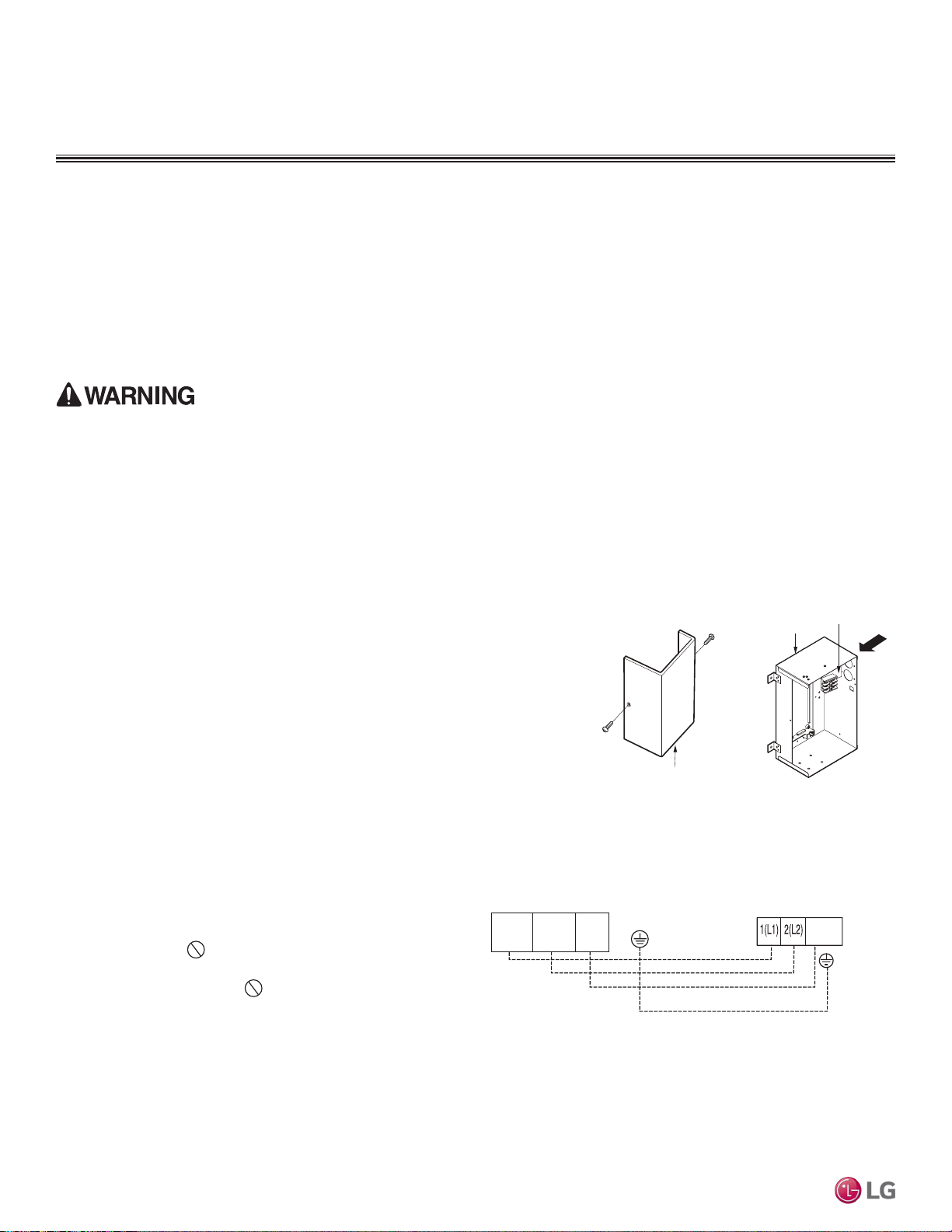
MULTI
F
MAX
MULTI
F
Power Wiring / Communications Cable Guidelines
Installation and Best Layout Practices
DUCT (HIGH STATIC) INDOOR UNITS
Connecting the Power Wiring and Communications Cable
1. To access the terminal block, first unscrew the cover from the control box.
2. Insert the power wiring / communications cable from the outdoor unit or branch
distribution unit (Multi F MAX systems only) through the sides of the indoor unit
and control box. Pass the wiring through the designated access holes to prevent
damage. To prevent electromagnetic interference and product malfunction, leave
a space between the power wiring and communications cable outside of the
indoor unit.
3. Connect each wire to its appropriate terminal on the indoor unit control board.
Verify that the color and terminal numbers from the outdoor unit or branch
distribution unit (Multi F MAX systems only) wiring match the color and terminal
numbers on the indoor unit.
4. Secure the power wiring / communications cable with the cable
restraint.
5. Screw the steel clamp to the inside of the control panel.
• Place the wiring / cables in the clamp and tighten the plastic
clamp to an open surface of the control panel.
• When clamping, do not apply force to the wiring connec-
tions.
• Neatly arrange the wiring, do not catch the wiring in the
electric box cover, and ensure the cover firmly closes.
6. Fill in any gaps around the wiring access holes with sealant to
prevent foreign particles from entering the indoor unit.
Figure 169:Accessing the Indoor Unit Terminal Block.
A
Control Box
Terminal Block
Control Box Cover
Indoor Unit Terminal Block
1(L1 )2(L2)
GND
3
Outdoor Unit Terminal Block or
Branch Distribution Unit Terminal Block
(Multi F MAX Systems Only)
GND
GRN /
YLW
BR
BL
RD
3 or S
Figure 170:Indoor Unit to Outdoor Unit / Branch Distribution Unit (Multi F
MAX systems only) Power Wiring / Communications Cable
Connections.
• Follow manufacturer’s circuit diagrams in the technical manuals.
• Confirm power source specifications.
• Confirm that the electrical capacity is sufficient.
• Starting current must be maintained ±10 percent of the rated current marked on the outdoor unit name plate.
• Confirm cable thickness specifications.
• It is required that a circuit breaker is installed, especially if conditions could become wet or moist.
• Include a disconnect in the power wiring system, add an air gap contact separation of at least 1/8 inch in each active (phase) conductor.
• Loose wiring will cause unit to malfunction, overheat, and catch fire, resulting in severe injury or death.
Note:
• Terminal screws will become loose during transport. Properly tighten the terminal connections during installation.
A voltage drop will cause the following problems:
• Magnetic switch vibration, fuse breaks, or disturbance to the normal function of an overload protection device.
• Compressor will not receive the proper starting current.
Due to our policy of continuous product innovation, some specications may change without notication.
©LG Electronics U.S.A., Inc., Englewood Cliffs, NJ. All rights reserved. “LG” is a registered trademark of LG Corp.
130 | DUCT (HIGH STATIC)
Multi F and Multi F MAX Indoor Unit Engineering Manual
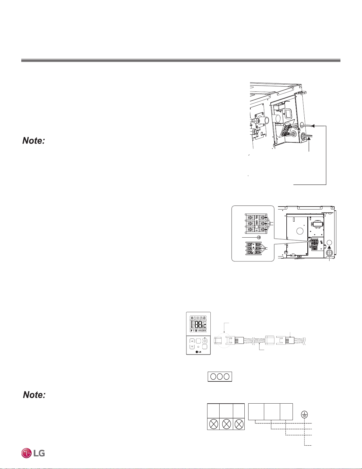
MULTI
F
MAX
MULTI
F
Installation and Best Layout Practices
DUCT (HIGH STATIC) INDOOR UNITS
Using a Conduit
1. Remove the rubber stopper on the indoor unit. Pass the power wiring / communica-
tions cable through the conduit, the conduit mounting plate, and to / through the
control panel of the indoor unit.
2. Connect the power wiring / communications cable to the indoor unit terminal block.
3. Screw the conduit mounting plate to the indoor unit.
4. Tighten the conduit and the conduit mounting plate together.
If the distance between the outdoor unit and indoor unit is greater than 131 feet, connect
the power wiring and communications cable separately (i.e., a conduit cannot be used).
Figure 172:PZCWRC1 LG Wired Remote Extension Cable.
Controller Options
Ceiling-concealed duct (high static) indoor units can be used with many LG-supplied wired controllers (sold separately). The wireless hand-
held controller (Model No. PQWRHQ0FDB) is also an optional accessory with use of the wired controller.
Figure 171:Exterior View of Conduit Installation.
Indoor Unit Terminal Block
1(L1 )2(L2)
GND
3
GRN /
YLW
BR
BL
RD
CN-REMO
YL
RD BK
Comm.
12V
Power
Ground
Wired Controller Connections
Controllers can connect to the indoor unit in one of two different
ways.
1. LG Wired Remote Extension Cable with Molex plug (PZCWRC1;
sold separately) that connects to the CN-REMO terminal on the
indoor unit PCB.
2. Field-supplied controller cable that connects to the indoor unit
terminal block (must be at least UL2547 or UL1007, 22 AWG,
two-core, one-shield core, at least FT-6 rated if local electric and
building codes require plenum cable usage).
Verify the connectors are properly inserted.
C/BOX Cable (Plug type)
Extension cable
To Indoor Unit
CN-REMO
Terminal
TEMP
FAN
SPEED
OPER
MODE
Figure 173:Wired Controller Connections on the Indoor Unit Terminal
Block.
When using eld-supplied controller cable, make sure to connect the yellow to
yellow (communications wire), red to red (12V power wire), and black to black
(ground wire) terminals from the remote controller to the indoor unit terminal
blocks.
Indoor power cable
Remote controller cable and
transmission cable between
the indoor unit and the
outdoor unit
Conduit Hole
GN/YL
Power Supply
High Voltage
(208/230 V)
Wired Remote
Controller
DUCT (HIGH STATIC) | 131
Ceiling-Concealed Duct (High Static)
Due to our policy of continuous product innovation, some specications may change without notication.
©LG Electronics U.S.A., Inc., Englewood Cliffs, NJ. All rights reserved. “LG” is a registered trademark of LG Corp.
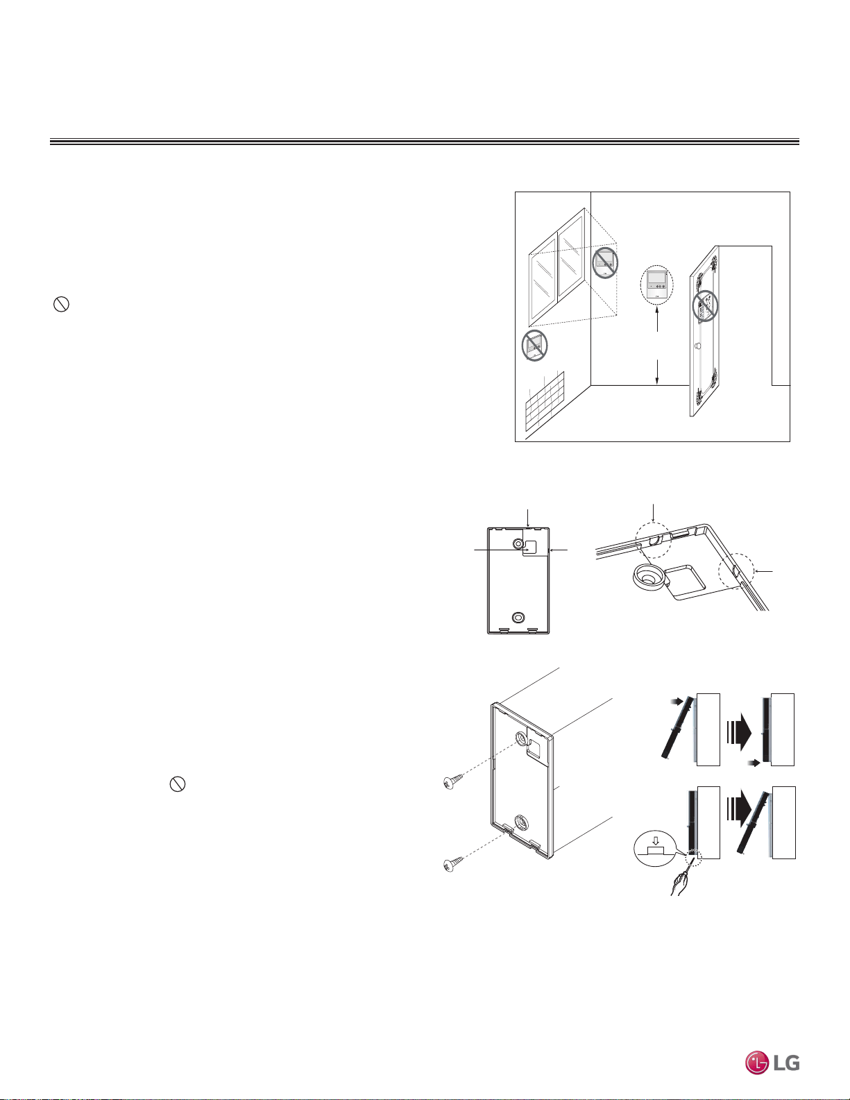
MULTI
F
MAX
MULTI
F
4 to 5 feet
above the floor
NO
NO
NO
YES
Remote Controller
TEMP
Remote Controller
TEMP
Re
m
ote Co
nt
r
ol
l
er
TEMP
Installation and Best Layout Practices
DUCT (HIGH STATIC) INDOOR UNITS
Wired Controller Placement
Assigning the Thermistor for Temperature Detection
Each indoor unit includes a return air thermistor assigned to sense the temperature. If a wired controller is installed, there is a choice of
sensing temperature with either the indoor unit return air thermistor or the thermistor in the wired controller. It is also an option to set both
thermistors to sense temperature so that indoor unit bases its operation on the first thermistor to reach the designated temperature differen-
tial. For applicable indoor units, an optional Remote Temperature Sensor can be used in lieu of the return air thermistor—either alone or in
conjunction with a wired controller thermistor as previously described.
Wired controllers include a sensor to detect room temperature. To maintain comfort
levels in the conditioned space, the wired controller must be installed in a location
away from direct sunlight, high humidity, and where it could be directly exposed to
cold air. Controller must be installed four (4) to five (5) feet above the floor where its
LED display can be read easily, in an area with good air circulation, and where it can
detect an average room temperature.
Do not install the wired controller near or in:
• Drafts or dead spots behind doors and in corners
• Hot or cold air from ducts
• Radiant heat from the sun or appliances
• Concealed pipes and chimneys
• An area where temperatures are uncontrolled, such as an outside wall
Figure 174:Proper Location for the Wired Controller.
Hanging the Wired Controller
1. The controller wiring / cable can be installed in one of three direc-
tions: top, back, or on the right side. If top or right side installation
is desired, remove cable guide grooves on the controller, and
then position wiring / cable on applicable side.
2. Choose and mark the area of installation, and then screw the wall
plate into place (using the provided parts). Install the controller
wall plate to fit the electrical box if one is present. Ensure that no
gaps exist between the wall plate and the wall itself.
3. Arrange wiring / cables so as not to interfere with the controller
circuitry. Position the wired controller on the wall plate. Snap into
place by pressing the bottom part of the wired controller onto
the wall plate. Make sure that no gaps exist between the wired
controller and the wall plate on all sides.
4. To remove wired controller from the wall plate, insert a screw-
driver into the two holes at the bottom. Twist screwdriver to
release controller. Do not damage the controller components
when removing.
Back
Top
Top
Right
Side
Right
Side
Wall Wall
Wall Wall
Installing the Controller
Removing the Controller
Figure 175:Removing the Cable Guide Grooves.
Figure 176:Attaching the Wall Plate.
Figure 177:Installing / Removing
the Controller.
Due to our policy of continuous product innovation, some specications may change without notication.
©LG Electronics U.S.A., Inc., Englewood Cliffs, NJ. All rights reserved. “LG” is a registered trademark of LG Corp.
132 | DUCT (HIGH STATIC)
Multi F and Multi F MAX Indoor Unit Engineering Manual
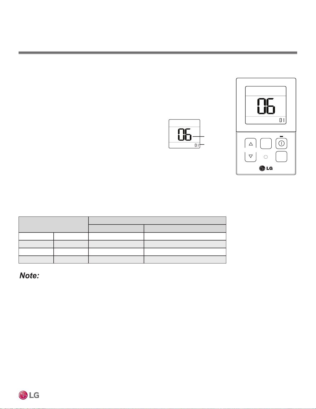
MULTI
F
MAX
MULTI
F
Installation and Best Layout Practices
DUCT (HIGH STATIC) INDOOR UNITS
1. To access system installer setting mode, press and hold the temperature increase and mode selection
buttons simultaneously for approximately three (3) seconds. Choose setting code value “06” by press-
ing the mode selection button.
2. Use the temperature increase and decrease buttons to select the
desired setting value.
Setting Values
3. Press the on / off button to save the established settings.
4. To deactivate system installer setting mode after the settings have been established, press and hold
the temperature increase and mode selection check buttons simultaneously for approximately three
(3) seconds. If a button is not pressed for more than 25 seconds, the system installer setting mode
will automatically deactivate.
• Select the position after verifying duct work and the external static pressure of the indoor unit.
• Factory set to pressure selection F-H.
Table 66:Static Pressure Setting Table.
Pressure Selection
Function
Zone State External Static Pressure Standard Value
01 V-H Variable High
02 F-H Fixed High
03 V-L Variable Low
04 F-L Fixed Low
TEM P
FA N
SPEED
OPER
MODE
Code
Set Value
Figure 178:Select Code and
Set Value.
01 : V-H
02 : F-H
03 : V-L
04 : F-L
Figure 179:Controller External
Static Pressure Setting Display.
External Static Pressure Control
To provide a required air flow rate that accounts for the external static pressure change, follow the steps
below.
DUCT (HIGH STATIC) | 133
Ceiling-Concealed Duct (High Static)
Due to our policy of continuous product innovation, some specications may change without notication.
©LG Electronics U.S.A., Inc., Englewood Cliffs, NJ. All rights reserved. “LG” is a registered trademark of LG Corp.
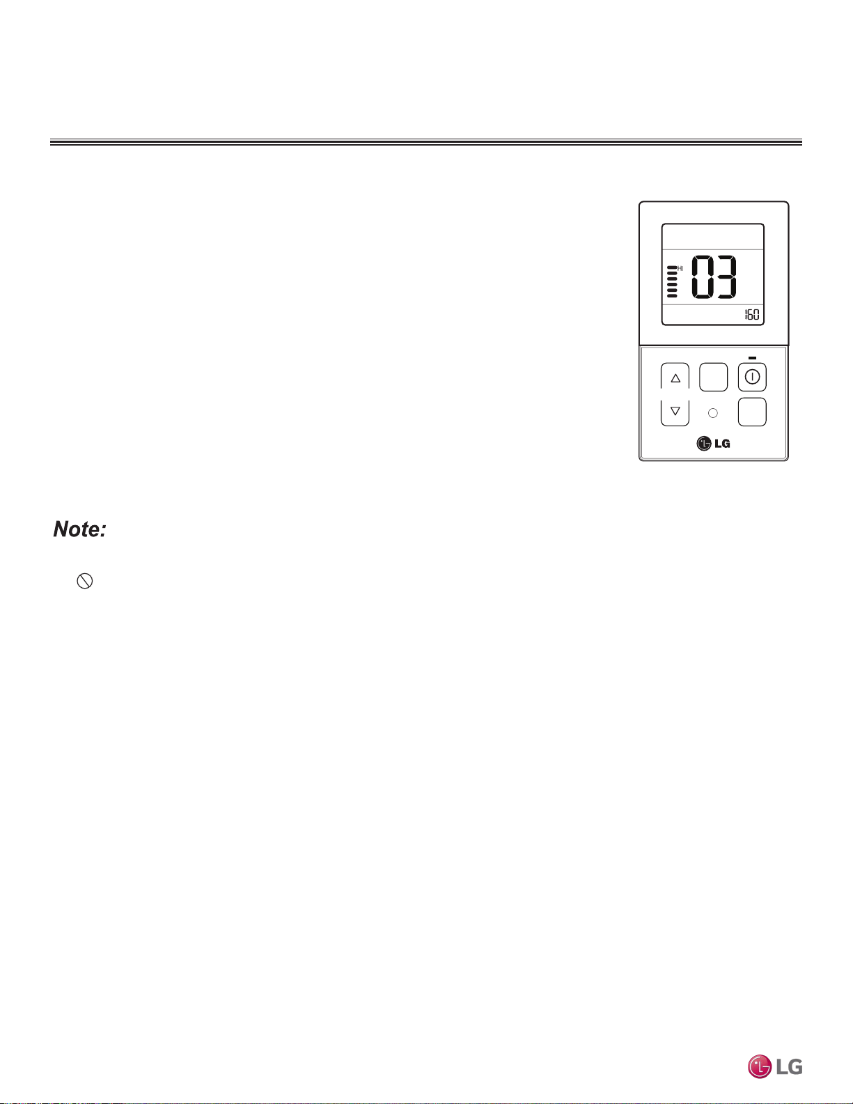
MULTI
F
MAX
MULTI
F
TEMP
FA N
SPEED
OPER
MODE
Figure 180:Controller External
Static Pressure Setting Display.
• A certified technician must set the external static pressure value(s). If the external static pressure is set incorrectly, the system will
malfunction.
• Do not alter the external static pressure value that corresponds to each air flow level.
• External static pressure value can vary depending on the indoor unit.
• If by pressing the fan speed button during external static pressure setup, the fan speed is raised to the next level, the air flow value of
the previous fan speed will be maintained (external static pressure setting value is saved).
Assigning Air Flow
To assign an air flow for each fan speed, follow the steps below.
1. To access system installer setting mode, press and hold the temperature increase and mode selection
buttons simultaneously for approximately three (3) seconds. Choose setting code value “03” by press-
ing the mode selection button.
2. Use the fan speed button to select the desired fan speed. ( Lo→Med→Hi will display on the LED).
3. Use the temperature increase and decrease buttons to select the desired external static pressure set-
ting value (thereby assigning the respective airflow). External static pressure value range: 0~255; the
value will display near the lower right corner of the LED.
4. Press the on / off button to save the established settings.
5. To deactivate system installer setting mode after the settings have been established, press and hold
the temperature increase and mode selection check buttons simultaneously for approximately three
(3) seconds. If a button is not pressed for more than 25 seconds, the system installer setting mode
will automatically deactivate.
Installation and Best Layout Practices
DUCT (HIGH STATIC) INDOOR UNITS
Due to our policy of continuous product innovation, some specications may change without notication.
©LG Electronics U.S.A., Inc., Englewood Cliffs, NJ. All rights reserved. “LG” is a registered trademark of LG Corp.
134 | DUCT (HIGH STATIC)
Multi F and Multi F MAX Indoor Unit Engineering Manual

FOUR-WAY
CEILING-CASSETTE
INDOOR UNIT DATA
“Mechanical Specifications” on page 136
“General Data / Specifications” on page 137
“Dimensions” on page 138
“Cooling Capacity Table” on page 140
“Heating Capacity Table” on page 142
“Acoustic Data” on page 144
“Air Velocity and Temperature Distribution” on page 146
“Refrigerant Flow Diagram” on page 148
“Wiring Diagram” on page 149
“Factory Supplied Parts and Materials” on page 150
“Installation and Best Layout Practices” on page 151

FOUR-WAY CEILING CASSETTE INDOOR UNITS
Mechanical Specications and Features
Four-Way Ceiling-Cassette Indoor Units
General
All LG indoor units are factory assembled, wired, piped, and pro-
vided with a control circuit board, fan, and motor. Four-way ceiling-
cassette units have a sound rating no higher than 38 dB(A) as tested
per KSA0701 ISO Standard 3745.
Coil
Indoor unit coils are factory built and are comprised of aluminum fins
mechanically bonded to copper tubing. Each unit has two rows of
coils, which are pressure tested at the factory. Each unit is provided
with a factory installed condensate drain pan below the coil.
Refrigerant System
System is designed for use with R410A refrigerant. The refrigeration
circuit is pressure-tested at the factory and shipped with a holding
charge of helium gas. Refrigerant pipe connections are 45° flare,
and all refrigerant lines from the outdoor unit to the indoor units must
be field insulated.
Electrical
Each indoor unit is designed to operate using 208–230/60/1 power
with voltage variances of ±10%.
Casing
The case is constructed of a galvanized steel plate designed to recess
in the ceiling, and has a surface mounted concentric grille on the bot-
tom of the unit. Unit has four supply air outlets and one return air inlet.
Ventilation Air
The case has a factory designated knockouts to connect a field-
supplied, pressurized, and filtered outside air duct.
Fan Assembly and Control
All indoor units have a single, direct-drive turbo fan. Fans are manu-
factured of high-strength ABS HT-700 polymeric resin that is statically
and dynamically balanced. The fan motor is brushless digitally con-
trolled (BLDC) with permanently lubricated and sealed ball bearings.
The fan / motor assembly is mounted on vibration-attenuating rubber
grommets. Fan speed is controlled using a microprocessor-based di-
rect digital control algorithm that provides pre-programmed, eld-se-
lectable xed or auto fan speeds in the Heating and Cooling modes.
The indoor fan has Low, Med, High, Power Cool and Auto settings
for Cooling mode; and has Low, Med, High, and Auto settings for
Heating mode. Auto setting adjusts the fan speed based on the dif-
ference between the controller setpoint and space temperature.
Air Filter
Return air is filtered with a factory-supplied, 14" x 14" x 1", remov-
able, washable filter accessible from the bottom of the unit.
Architectural Grille
An architectural grille is sold as a
separate required accessory. The
four-way grille is off-white acry-
lonitrile butadiene styrene (ABS)
polymeric resin with a tapered trim
edge.
Airflow Guide Vanes
The supply air outlet has four-di-
rectional slot diffusers, each equipped with an independent oscillat-
ing motorized guide vane to change airow direction. A guide vane
algorithm sequentially changes the predominant discharge airow
direction in counterclockwise pattern, or can be used to lock each
guide vane independently in a eld-adjusted xed position. The four
vanes can be individually adjusted from the wired remote controller to
customize the airow pattern for the conditioned space. A setting in
the cooling and heating modes can cycle the vanes up and down for
uniform / random air distribution.
Microprocessor Control
The indoor unit is provided with an integrated control panel to com-
municate with the outdoor unit. All unit operation parameters are
stored in non-volatile memory residing on the unit microprocessor.
The microprocessor controls space temperature through using the
value provided by the temperature sensor within the indoor unit.
The microprocessor control will activate indoor unit operation when
the indoor room temperature falls below or rises above a setpoint
temperature, at which point, a signal is sent to the outdoor unit to
begin the appropriate mode. The microprocessor will also provide
self-diagnostics and auto restart functions. A field-supplied four-
wire power / communications cable must be installed to connect the
indoor unit(s) to the outdoor unit.
The indoor units are Wi-Fi compatible with the addition of an LG Wi-
Fi module accessory, and can be controlled by LG’s Smart ThinQ™
app on a smart device. A field-supplied Wi-Fi network and smart
device are required. The Smart ThinQ app is free, and is available
for Android™ and iOS. (Android is a trademark of Google LLC.)
Controls
The indoor unit casing has a factory-standard, integral infrared
sensor designed to communicate with the supplied LG wireless
handheld remote controller. An optional wired controller is available
as an additional accessory. Communication between the indoor units
and the outdoor unit is accomplished through 14 AWG, four-core,
stranded and shielded power / communication cable.
Condensate Lift/Pump
The indoor unit is provided with a factory installed and wired internal
condensate lift/pump capable of providing a minimum 27.5 inch lift
from the bottom surface of the unit. Drain pump has a safety switch to
shut off the indoor unit if the condensate rises too high in the drain pan.
• Inverter (Variable speed fan)
• Internal drain pump
• Jet cool
• Control lock function
• Auto operation
• Auto restart operation
• 24-Hour on/off timer
• Two thermistor control
• Required accessory grille (PT-QCHW0)
sold separately
• Group Control
• Wireless LCD remote control included;
wired thermostat available (sold separately)
• Wi-Fi compatible
Features
Figure 181:Multi F Four-Way
Ceiling-Cassette Indoor Unit.
Due to our policy of continuous product innovation, some specications may change without notication.
©LG Electronics U.S.A., Inc., Englewood Cliffs, NJ. All rights reserved. “LG” is a registered trademark of LG Corp.
136 | CEILING-CASSETTE
Multi F and Multi F MAX Indoor Unit Engineering Manual
MULTI
F
MAX
MULTI
F
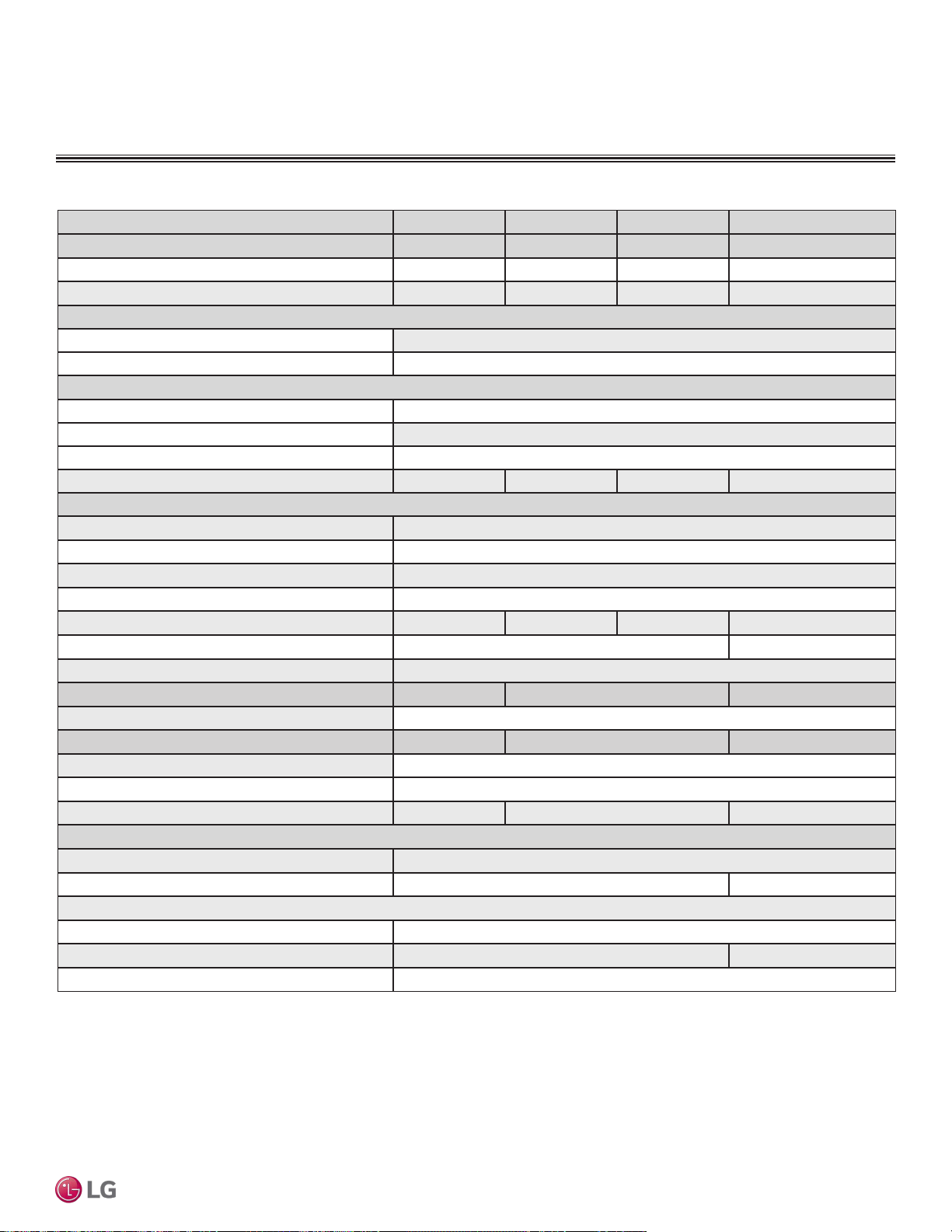
General Data / Specications
Model Name LMCN078HV LCN098HV4 LCN128HV4 LCN188HV4
Grille (Sold Separately) PT-QCHW0 PT-QCHW0 PT-QCHW0 PT-QCHW0
Nominal Cooling Capacity (Btu/h)
1
7,000 9,000 12,000 18,000
Nominal Heating Capacity (Btu/h)
1
8,100 10,400 13,800 20,800
Operating Range
Cooling (°F WB)
57-77
Heating (°F DB)
59-81
Fan
Type
Turbo
Motor Output (W) x Qty.
43 x 1
Motor/Drive
Brushless Digitally Controlled / Direct
Airflow Rate CFM (H/M/L)
265 / 212 / 177 300 / 265 / 230 335 / 283 / 247 459 / 424 / 388
Unit Data
Refrigerant Type
2
R410A
Refrigerant Control
EEV
Power Supply V, Ø, Hz
3
208-230, 1, 60
Rated Amps (A)
0.25
Sound Pressure Level dB(A) (H/M/L)
4
31 / 27 / 24 36 / 33 / 30 38 / 35 / 32 41 / 39 / 36
Body Dimensions (W x H x D, in.)
22-7/16 x 8-7/16 x 22-7/16 22-7/16 x 10-3/32 x 22-7/16
Grille (Sold separately) Dimensions (WxHxD, in.)
27-9/16 x 7/8 x 27-9/16
Body Net Weight (lbs.)
26 29 32
Grille (Sold separately) Net Weight (lbs.)
7
Body Shipping Weight (lbs.)
31 34 39
Grille (Sold separately) Shipping Weight (lbs.)
9
Power Wiring / Communications Cable (No. x AWG)
5
4 x 14
Heat Exchanger (Row x Column x Fin / inch) x Number
(1 X 8 X 18) X 1 (2 x 8 x 18) x 1 (2 x 10 x 18) x 1
Pipe Size
Liquid (in.)
1/4
Vapor (in.)
3/8 1/2
Connection Size
Liquid (in.)
1/4
Vapor (in.)
3/8 1/2
Drain O.D. / I.D. (in.)
1-1/4, 1
1
Nominal capacity is rated 0 ft. above sea level with a 0 ft. level difference between outdoor and indoor
units. All capacities are net with a combination ratio between 95 – 105%.
Nominal cooling capacity rating obtained with air entering the indoor unit at 80ºF dry bulb (DB) and 67ºF
wet bulb (WB) and outdoor ambient conditions of 95ºF dry bulb (DB) and 75ºF wet bulb (WB).
Nominal heating capacity rating obtained with air entering the indoor unit at 70ºF dry bulb (DB) and 60ºF
wet bulb (WB) and outdoor ambient conditions of 47ºF dry bulb (DB) and 43ºF wet bulb (WB).
2
This unit comes with a dry helium charge.
3
Acceptable operating voltage: 187V-253V.
4
Sound pressure levels are tested in an anechoic chamber under ISO Standard 3745 and are the
same in both cooling and heating mode. These values can increase due to ambient conditions during
operation.
5
All power wiring / communications cable to the IDUs be minimum 14 AWG, 4-conductor, stranded,
shielded or unshielded (if shielded, must be grounded to chassis at ODU only) and must comply with
applicable local and national codes.
Table 66:Multi F Four-Way Ceiling-Cassette Indoor Unit General Data.
FOUR-WAY CEILING-CASSETTE INDOOR UNITS
CEILING-CASSETTE | 137
Four-Way Ceiling-Cassette
Due to our policy of continuous product innovation, some specications may change without notication.
©LG Electronics U.S.A., Inc., Englewood Cliffs, NJ. All rights reserved. “LG” is a registered trademark of LG Corp.
MULTI
F
MAX
MULTI
F
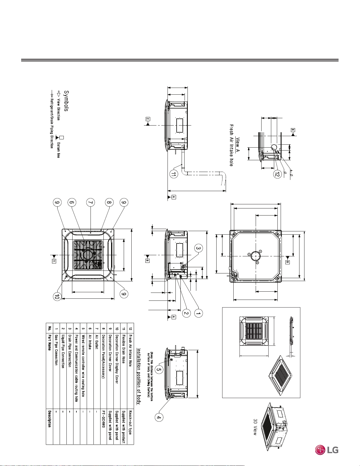
Dimensions
FOUR-WAY CEILING-CASSETTE INDOOR UNITS
Figure 182:LMCN078HV, LCN098HV4, and LCN128HV4 Dimensions.
23-5/8 (600) (Ceiling Opening)
Unit: Inch (mm])
4-17/32
(115)
2-51/64
(71)
2-51/64
(71)
4-17/32
(115)
7/64
(3)
2-3/4
(70)
5-29/32
(150)
5-29/32
(150)
20-23/64 (517) (Hanging Bolt)
10-13/64 (259)
10-13/64 (259)
10-13/64 (259)
23-5/8 (600) (Ceiling Opening)
20-23/64 (517) (Hanging Bolt)
20-19/32 (523) (Hanging Bolt)
10-13/64 (259)
5-19/32
(142)
9-19/64 (236)
7-61/64
(202)
7-61/64
(202)
Max. Condensate Lift: 27-916
(700) or less
22-7/16 (570)
1-31/32
(50)
18-5/32 (461) (Hanging Bolt)
1-3/16
(30)
63/64
(25)
63/64
(25)
7-13/64
(183)
1-11/32
(34)
3-21/32
(93)
6-1/16
(154)
24-13/32 (620)
14-29/32 (379) (Air Outlet Hole)
24-13/32 (620)
22-7/16 (570)
14-29/32 (379)
(Air Outlet Hole)
1
11
32
24-13/32 (620)
24-13/32 (620)
PT-QCHW0
Due to our policy of continuous product innovation, some specications may change without notication.
©LG Electronics U.S.A., Inc., Englewood Cliffs, NJ. All rights reserved. “LG” is a registered trademark of LG Corp.
138 | CEILING-CASSETTE
Multi F and Multi F MAX Indoor Unit Engineering Manual
MULTI
F
MAX
MULTI
F
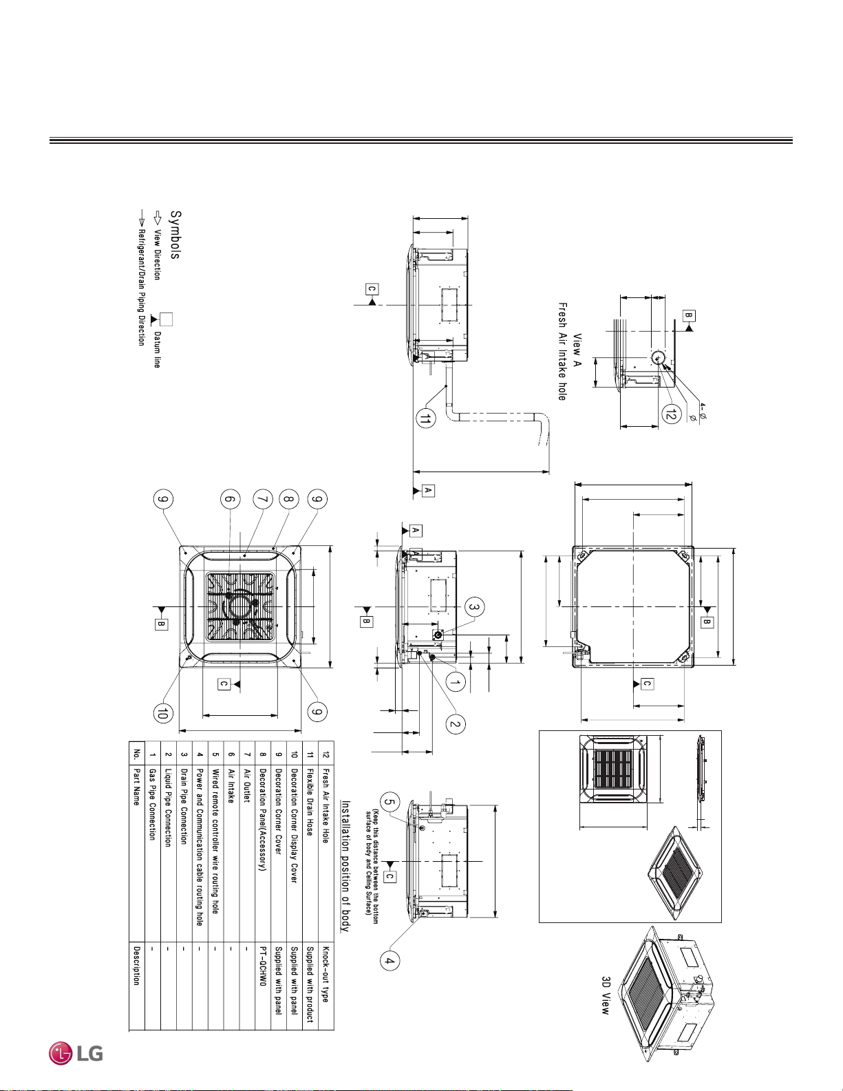
Dimensions
FOUR-WAY CEILING-CASSETTE INDOOR UNITS
Figure 183:LCN188HV4 Dimensions.
Unit: Inch (mm)
2-51/64
(71)
5-29/32
(150)
7/64
(3)
2-3/4
(70)
6-3/16
(157)
7-9/16
(192)
23-5/8 (600) (Ceiling Opening)
23-5/8 (600) (Ceiling Opening)
20-23/64 (517) (Hanging Bolt)
20-23/64 (517) (Hanging Bolt)
10-13/64 (259)
10-13/64 (259)
10-13/64 (259)
10-13/64 (259)
20-19/32 (523) (Hanging Bolt)
18-5/32 (461) (Hanging Bolt)
22-7/16 (570)
22-7/16 (570)
5-19/32
(142)
1-31/32
(50)
1-3/16
(30)
63/64
(25)
63/64
(25)
7-13/64
(183)
1-11/32
(34)
3-1/2
(89)
6-1/16
(154)
24-13/32 (620)
14-29/32 (379) (Air Outlet Hole)
24-13/32 (620)
14-29/32 (379)
(Air Outlet Hole)
Max. Condensate Lift: 27-916
(700) or less
7-61/64
(202)
7-61/64
(202)
11
(279)
1
11
32
24-13/32 (620)
24-13/32 (620)
PT-QCHW0
CEILING-CASSETTE | 139
Four-Way Ceiling-Cassette
Due to our policy of continuous product innovation, some specications may change without notication.
©LG Electronics U.S.A., Inc., Englewood Cliffs, NJ. All rights reserved. “LG” is a registered trademark of LG Corp.
MULTI
F
MAX
MULTI
F
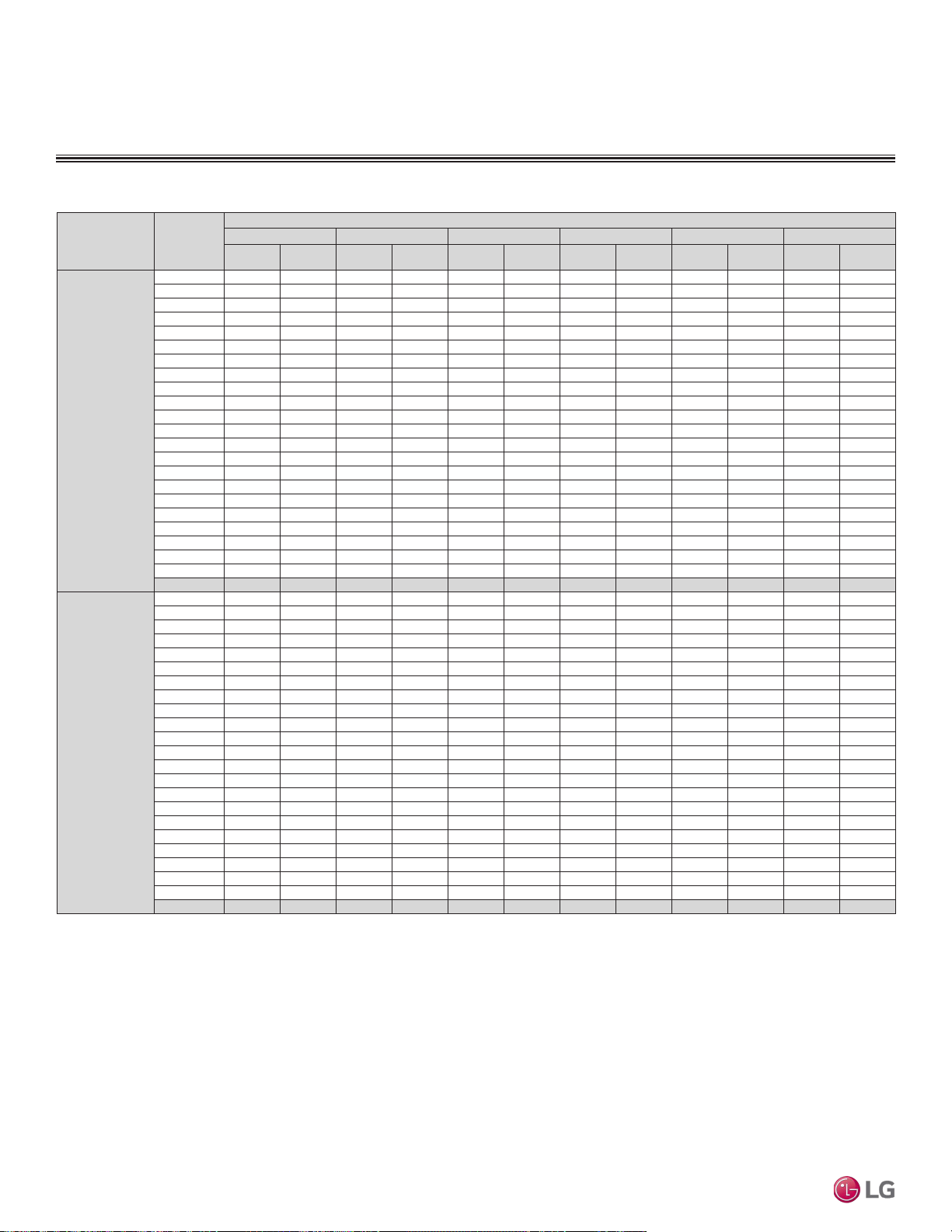
Cooling Capacity Table
FOUR-WAY CEILING CASSETTE INDOOR UNITS
Table 67:Multi F Four-Way Ceiling-Cassette Indoor Units Cooling Capacity Table.
Model No. /
Nominal Capacity
of Indoor Unit
(Btu/h)
Outdoor Air
Temp.
(°F DB)
Indoor Air Temp. °F DB / °F WB
68 / 57 73 / 61 77 / 64 80 / 67 86 / 72 90 / 75
TC SHC TC SHC TC SHC TC SHC TC SHC TC SHC
LMCN078HV
7,000
14 6.86 4.87 7.29 5.15 7.71 4.99 8.02 5.09 8.57 5.13 8.99 5.23
20 6.86 4.91 7.28 5.19 7.71 5.02 8.02 5.13 8.56 5.17 8.99 5.27
25 6.85 4.95 7.28 5.23 7.70 5.06 8.01 5.17 8.55 5.21 8.98 5.31
30 6.85 4.99 7.27 5.27 7.70 5.10 8.00 5.21 8.55 5.25 8.97 5.35
35 6.84 5.03 7.27 5.31 7.69 5.14 8.00 5.25 8.54 5.29 8.97 5.39
40 6.84 5.06 7.26 5.35 7.68 5.18 7.99 5.29 8.53 5.33 8.96 5.43
45 6.83 5.10 7.25 5.39 7.68 5.22 7.99 5.33 8.53 5.37 8.95 5.47
50 6.83 5.14 7.25 5.43 7.67 5.26 7.98 5.37 8.52 5.41 8.94 5.52
55 6.82 5.18 7.24 5.47 7.67 5.30 7.97 5.41 8.51 5.45 8.94 5.56
60 6.81 5.21 7.24 5.51 7.66 5.33 7.97 5.45 8.51 5.49 8.93 5.60
65 6.81 5.25 7.23 5.55 7.66 5.37 7.96 5.49 8.50 5.53 8.92 5.64
70 6.80 5.29 7.23 5.59 7.65 5.41 7.95 5.52 8.49 5.57 8.92 5.68
75 6.64 5.20 7.06 5.50 7.48 5.33 7.79 5.45 8.33 5.50 8.75 5.61
80 6.48 5.11 6.90 5.42 7.32 5.26 7.62 5.38 8.16 5.43 8.58 5.55
85 6.31 5.02 6.73 5.33 7.15 5.17 7.46 5.30 7.99 5.36 8.41 5.48
90 6.15 4.93 6.57 5.23 6.99 5.09 7.29 5.21 7.83 5.29 8.24 5.40
95 5.98 4.87 6.39 5.19 6.81 5.05 7.00 5.10 7.64 5.26 8.06 5.38
100 5.83 4.74 6.25 5.05 6.66 4.93 6.91 5.02 7.50 5.14 7.91 5.27
105 5.69 4.61 6.10 4.92 6.52 4.81 6.82 4.94 7.35 5.03 7.77 5.16
110 5.54 4.46 5.96 4.76 6.37 4.66 6.67 4.79 7.21 4.89 7.62 5.02
115 5.39 4.32 5.81 4.63 6.23 4.54 6.53 4.67 7.06 4.77 7.48 4.90
118 5.31 4.29 5.72 4.60 6.14 4.52 6.44 4.65 6.97 4.76 7.39 4.89
122 5.28 4.28 5.69 4.59 6.11 4.51 6.41 4.64 6.94 4.75 7.36 4.89
LCN098HV4
9,000
14 8.82 6.31 9.37 6.66 9.92 6.45 10.31 6.59 11.01 6.64 11.56 6.77
20 8.82 6.36 9.36 6.72 9.91 6.50 10.31 6.64 11.01 6.70 11.55 6.82
25 8.81 6.41 9.36 6.77 9.90 6.55 10.30 6.69 11.00 6.75 11.54 6.87
30 8.80 6.46 9.35 6.82 9.90 6.60 10.29 6.74 10.99 6.80 11.54 6.93
35 8.80 6.50 9.34 6.87 9.89 6.65 10.28 6.79 10.98 6.85 11.53 6.98
40 8.79 6.55 9.33 6.92 9.88 6.70 10.27 6.84 10.97 6.90 11.52 7.03
45 8.78 6.60 9.33 6.97 9.87 6.75 10.27 6.90 10.96 6.95 11.51 7.09
50 8.78 6.65 9.32 7.03 9.87 6.80 10.26 6.95 10.96 7.00 11.50 7.14
55 8.77 6.70 9.31 7.08 9.86 6.85 10.25 7.00 10.95 7.06 11.49 7.19
60 8.76 6.75 9.31 7.13 9.85 6.90 10.24 7.05 10.94 7.11 11.48 7.24
65 8.76 6.80 9.30 7.18 9.84 6.95 10.24 7.10 10.93 7.16 11.47 7.29
70 8.75 6.85 9.29 7.23 9.84 7.00 10.23 7.15 10.92 7.21 11.47 7.35
75 8.54 6.73 9.08 7.12 9.62 6.90 10.01 7.05 10.71 7.12 11.25 7.26
80 8.33 6.62 8.87 7.01 9.41 6.80 9.80 6.96 10.49 7.03 11.03 7.18
85 8.12 6.50 8.66 6.89 9.20 6.70 9.59 6.85 10.28 6.94 10.82 7.09
90 7.91 6.37 8.45 6.77 8.99 6.59 9.37 6.75 10.06 6.84 10.60 6.99
95 7.68 6.31 8.22 6.71 8.75 6.54 9.00 6.60 9.83 6.80 10.36 6.96
100 7.50 6.14 8.03 6.54 8.57 6.38 8.88 6.50 9.64 6.66 10.17 6.82
105 7.31 5.97 7.84 6.37 8.38 6.23 8.77 6.40 9.45 6.51 9.99 6.68
110 7.12 5.77 7.66 6.17 8.19 6.03 8.58 6.20 9.26 6.33 9.80 6.50
115 6.94 5.59 7.47 5.99 8.01 5.87 8.39 6.05 9.08 6.18 9.61 6.35
118 6.82 5.55 7.36 5.96 7.89 5.84 8.28 6.02 8.96 6.15 9.50 6.33
122 6.79 5.54 7.32 5.94 7.86 5.83 8.24 6.01 8.93 6.15 9.46 6.32
TC = Total Capacity (kBtu/h).
SHC: Sensible Heat Capacity (kBtu/h).
Nominal capacity as rated 0 ft. above sea level and a 0 ft. level difference between outdoor and indoor units. Corresponding refrigerant piping length is accordance with standard length of each outdoor unit.
Nominal cooling capacity rating obtained with air entering the indoor unit at 80ºF dry bulb (DB) and 67ºF wet bulb (WB), and outdoor ambient conditions of 95ºF dry bulb (DB) and 75ºF wet bulb (WB).
The shaded table columns and rows indicate reference data. When operating at this temperature, these values can be different if the system is not running consistently.
Due to our policy of continuous product innovation, some specications may change without notication.
©LG Electronics U.S.A., Inc., Englewood Cliffs, NJ. All rights reserved. “LG” is a registered trademark of LG Corp.
140 | CEILING-CASSETTE
Multi F and Multi F MAX Indoor Unit Engineering Manual
MULTI
F
MAX
MULTI
F

Table 68:Multi F Four-Way Ceiling-Cassette Indoor Units Cooling Capacity Table.
TC = Total Capacity (kBtu/h).
SHC: Sensible Heat Capacity (kBtu/h).
Nominal capacity as rated 0 ft. above sea level and a 0 ft. level difference between outdoor and indoor units. Corresponding refrigerant piping length is accordance with standard length of each outdoor unit.
Nominal cooling capacity rating obtained with air entering the indoor unit at 80ºF dry bulb (DB) and 67ºF wet bulb (WB), and outdoor ambient conditions of 95ºF dry bulb (DB) and 75ºF wet bulb (WB).
The shaded table columns and rows indicate reference data. When operating at this temperature, these values can be different if the system is not running consistently.
Model No. /
Nominal Capacity
of Indoor Unit
(Btu/h)
Outdoor Air
Temp.
(°F DB)
Indoor Air Temp. °F DB / °F WB
68 / 57 73 / 61 77 / 64 80 / 67 86 / 72 90 / 75
TC SHC TC SHC TC SHC TC SHC TC SHC TC SHC
LCN128HV4
12,000
14 11.76 8.51 12.49 8.99 13.22 8.70 13.75 8.88 14.69 8.96 15.42 9.13
20 11.75 8.57 12.48 9.06 13.21 8.77 13.74 8.95 14.67 9.03 15.40 9.20
25 11.75 8.64 12.48 9.13 13.20 8.84 13.73 9.02 14.66 9.10 15.39 9.27
30 11.74 8.71 12.47 9.20 13.19 8.90 13.72 9.09 14.65 9.17 15.38 9.34
35 11.73 8.77 12.46 9.27 13.18 8.97 13.71 9.16 14.64 9.24 15.37 9.41
40 11.72 8.84 12.45 9.34 13.17 9.04 13.70 9.23 14.63 9.31 15.36 9.48
45 11.71 8.90 12.44 9.41 13.16 9.11 13.69 9.30 14.62 9.38 15.35 9.55
50 11.70 8.97 12.43 9.47 13.15 9.17 13.68 9.37 14.61 9.45 15.33 9.62
55 11.69 9.03 12.42 9.54 13.14 9.24 13.67 9.44 14.60 9.52 15.32 9.70
60 11.68 9.10 12.41 9.61 13.13 9.31 13.66 9.50 14.59 9.58 15.31 9.77
65 11.67 9.17 12.40 9.68 13.12 9.38 13.65 9.57 14.57 9.65 15.30 9.84
70 11.66 9.23 12.39 9.75 13.11 9.44 13.64 9.64 14.56 9.72 15.29 9.91
75 11.38 9.08 12.11 9.60 12.83 9.31 13.35 9.51 14.27 9.60 15.00 9.79
80 11.10 8.92 11.82 9.45 12.55 9.17 13.07 9.38 13.99 9.48 14.71 9.68
85 10.83 8.76 11.54 9.29 12.26 9.03 12.78 9.24 13.70 9.36 14.42 9.56
90 10.55 8.60 11.26 9.13 11.98 8.88 12.50 9.10 13.42 9.22 14.13 9.43
95 10.25 8.51 10.96 9.05 11.67 8.82 12.00 8.90 13.10 9.18 13.81 9.39
100 10.00 8.28 10.71 8.82 11.42 8.61 11.84 8.76 12.85 8.98 13.56 9.20
105 9.75 8.05 10.46 8.59 11.17 8.40 11.69 8.62 12.60 8.78 13.31 9.01
110 9.50 7.77 10.21 8.31 10.92 8.14 11.44 8.37 12.35 8.53 13.07 8.76
115 9.25 7.54 9.96 8.08 10.67 7.92 11.19 8.15 12.10 8.33 12.82 8.56
118 9.10 7.49 9.81 8.03 10.52 7.88 11.04 8.12 11.95 8.30 12.67 8.54
122 9.05 7.47 9.76 8.01 10.48 7.87 10.99 8.11 11.90 8.29 12.62 8.53
LCN188HV4
18,000
14 17.65 12.33 18.74 13.02 19.84 12.61 20.63 12.88 22.03 12.98 23.12 13.23
20 17.63 12.43 18.73 13.13 19.82 12.71 20.61 12.98 22.01 13.09 23.11 13.33
25 17.62 12.52 18.71 13.23 19.81 12.81 20.60 13.08 22.00 13.19 23.09 13.44
30 17.60 12.62 18.70 13.33 19.79 12.91 20.58 13.18 21.98 13.29 23.07 13.54
35 17.59 12.71 18.68 13.43 19.78 13.00 20.57 13.28 21.96 13.39 23.05 13.64
40 17.58 12.81 18.67 13.53 19.76 13.10 20.55 13.38 21.94 13.49 23.04 13.75
45 17.56 12.90 18.66 13.63 19.75 13.20 20.53 13.48 21.93 13.59 23.02 13.85
50 17.55 13.00 18.64 13.73 19.73 13.30 20.52 13.58 21.91 13.69 23.00 13.95
55 17.54 13.10 18.63 13.83 19.72 13.39 20.50 13.68 21.89 13.79 22.98 14.05
60 17.52 13.19 18.61 13.93 19.70 13.49 20.49 13.78 21.88 13.89 22.97 14.16
65 17.51 13.29 18.60 14.03 19.69 13.59 20.47 13.87 21.86 13.99 22.95 14.26
70 17.50 13.38 18.58 14.13 19.67 13.69 20.46 13.97 21.84 14.09 22.93 14.36
75 17.08 13.16 18.16 13.92 19.24 13.49 20.03 13.79 21.41 13.92 22.50 14.20
80 16.66 12.93 17.74 13.70 18.82 13.30 19.60 13.60 20.98 13.75 22.06 14.03
85 16.24 12.70 17.32 13.47 18.40 13.09 19.17 13.40 20.55 13.56 21.63 13.85
90 15.82 12.46 16.90 13.23 17.97 12.88 18.75 13.19 20.12 13.37 21.20 13.67
95 15.37 12.33 16.44 13.12 17.51 12.78 18.00 12.90 19.65 13.30 20.72 13.61
100 14.99 12.00 16.06 12.78 17.13 12.47 17.77 12.70 19.28 13.01 20.35 13.33
105 14.62 11.67 15.69 12.45 16.76 12.17 17.53 12.50 18.90 12.73 19.97 13.05
110 14.24 11.27 15.32 12.05 16.39 11.79 17.16 12.13 18.53 12.36 19.60 12.70
115 13.87 10.93 14.94 11.71 16.01 11.48 16.79 11.82 18.15 12.07 19.22 12.41
118 13.65 10.85 14.72 11.64 15.79 11.42 16.56 11.77 17.93 12.03 19.00 12.37
122 13.57 10.83 14.64 11.62 15.71 11.40 16.49 11.75 17.85 12.01 18.92 12.36
Cooling Capacity Table
FOUR-WAY CEILING CASSETTE INDOOR UNITS
CEILING-CASSETTE | 141
Four-Way Ceiling-Cassette
Due to our policy of continuous product innovation, some specications may change without notication.
©LG Electronics U.S.A., Inc., Englewood Cliffs, NJ. All rights reserved. “LG” is a registered trademark of LG Corp.
MULTI
F
MAX
MULTI
F
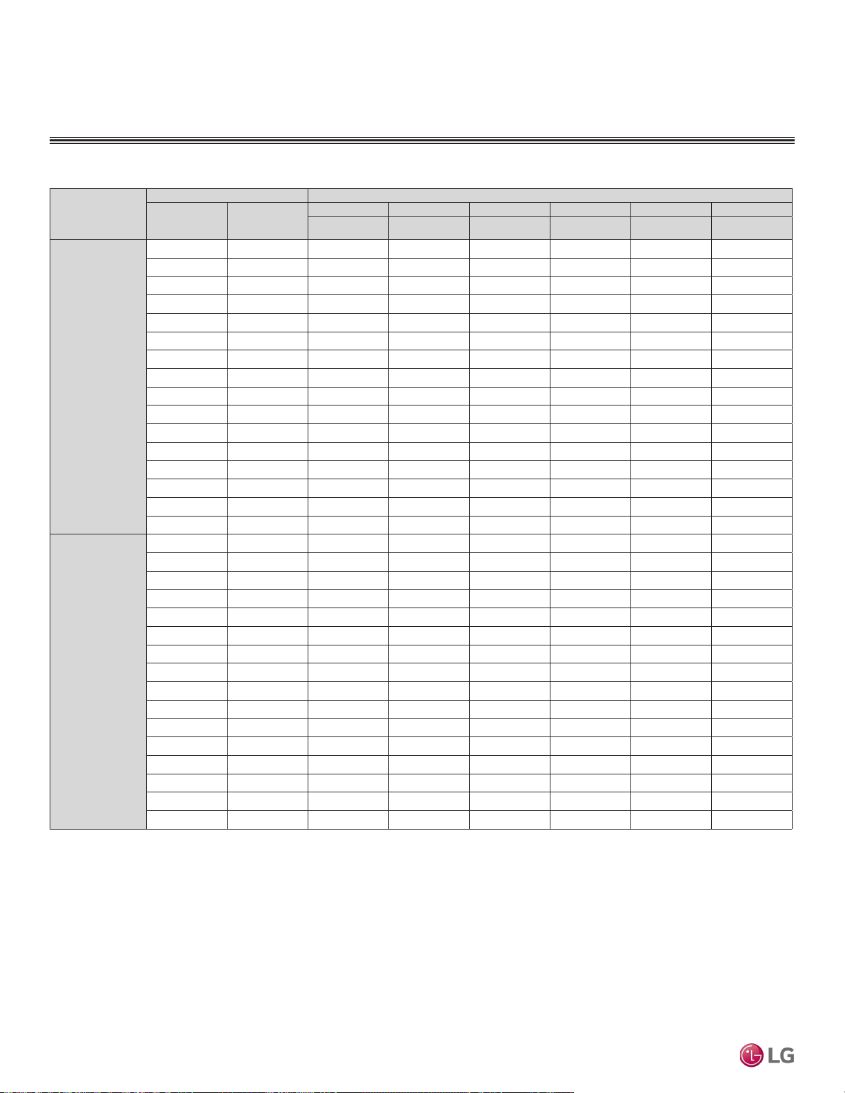
Table 69:Multi F Four-Way Ceiling-Cassette Indoor Units Heating Capacity Table.
Heating Capacity Table
FOUR-WAY CEILING-CASSETTE INDOOR UNITS
TC = Total Capacity (kBtu/h).
Nominal capacity as rated 0 ft. above sea level and a 0 ft. level difference between outdoor and indoor units. Corresponding refrigerant piping length is accordance with standard length of each outdoor unit.
Nominal heating capacity rating obtained with air entering the indoor unit at 70ºF dry bulb (DB) and 60ºF wet bulb (WB), and outdoor ambient conditions of 47ºF dry bulb (DB) and 43ºF wet bulb (WB).
Model No. /
Nominal Capacity of
Indoor Unit
(Btu/h)
Outdoor Air Temp. Indoor Air Temp. °F DB
°F DB °F WB
61 64 68 70 72 75
TC TC TC TC TC TC
LMCN078HV
7,000
0 -0.4 4.17 4.11 4.07 4.05 3.99 3.82
5 4.5 4.70 4.64 4.60 4.58 4.52 4.34
10 9 5.22 5.17 5.13 5.11 5.05 4.87
17 15 5.93 5.87 5.83 5.81 5.75 5.56
20 19 6.19 6.13 6.09 6.08 6.02 5.81
25 23 6.63 6.57 6.53 6.52 6.46 6.22
30 28 7.01 6.96 6.92 6.90 6.84 6.63
35 32 7.40 7.34 7.30 7.28 7.22 7.04
40 36 7.74 7.68 7.64 7.62 7.56 7.39
45 41 8.08 8.02 7.98 7.96 7.90 7.73
47 43 8.22 8.16 8.12 8.10 8.04 7.87
50 46 8.35 8.29 8.25 8.23 8.17 7.98
55 51 8.57 8.51 8.47 8.45 8.39 8.16
60 56 8.57 8.51 8.47 8.45 8.39 8.20
63 59 8.57 8.51 8.47 8.45 8.39 8.22
68 64 8.57 8.51 8.47 8.45 8.39 8.25
LCN098HV4
9,000
0 -0.4 5.35 5.28 5.23 5.20 5.12 4.90
5 4.5 6.03 5.95 5.90 5.88 5.80 5.58
10 9 6.71 6.63 6.58 6.56 6.48 6.26
17 15 7.61 7.54 7.49 7.46 7.39 7.14
20 19 7.95 7.88 7.83 7.80 7.72 7.46
25 23 8.52 8.44 8.39 8.37 8.29 7.99
30 28 9.01 8.93 8.88 8.86 8.78 8.52
35 32 9.50 9.42 9.37 9.34 9.27 9.04
40 36 9.94 9.86 9.81 9.78 9.71 9.48
45 41 10.37 10.30 10.25 10.22 10.15 9.92
47 43 10.55 10.48 10.43 10.40 10.32 10.10
50 46 10.72 10.64 10.59 10.57 10.49 10.24
55 51 11.00 10.93 10.88 10.85 10.78 10.48
60 56 11.00 10.93 10.88 10.85 10.78 10.52
63 59 11.00 10.93 10.88 10.85 10.78 10.55
68 64 11.00 10.93 10.88 10.85 10.78 10.60
Due to our policy of continuous product innovation, some specications may change without notication.
©LG Electronics U.S.A., Inc., Englewood Cliffs, NJ. All rights reserved. “LG” is a registered trademark of LG Corp.
142 | CEILING-CASSETTE
Multi F and Multi F MAX Indoor Unit Engineering Manual
MULTI
F
MAX
MULTI
F
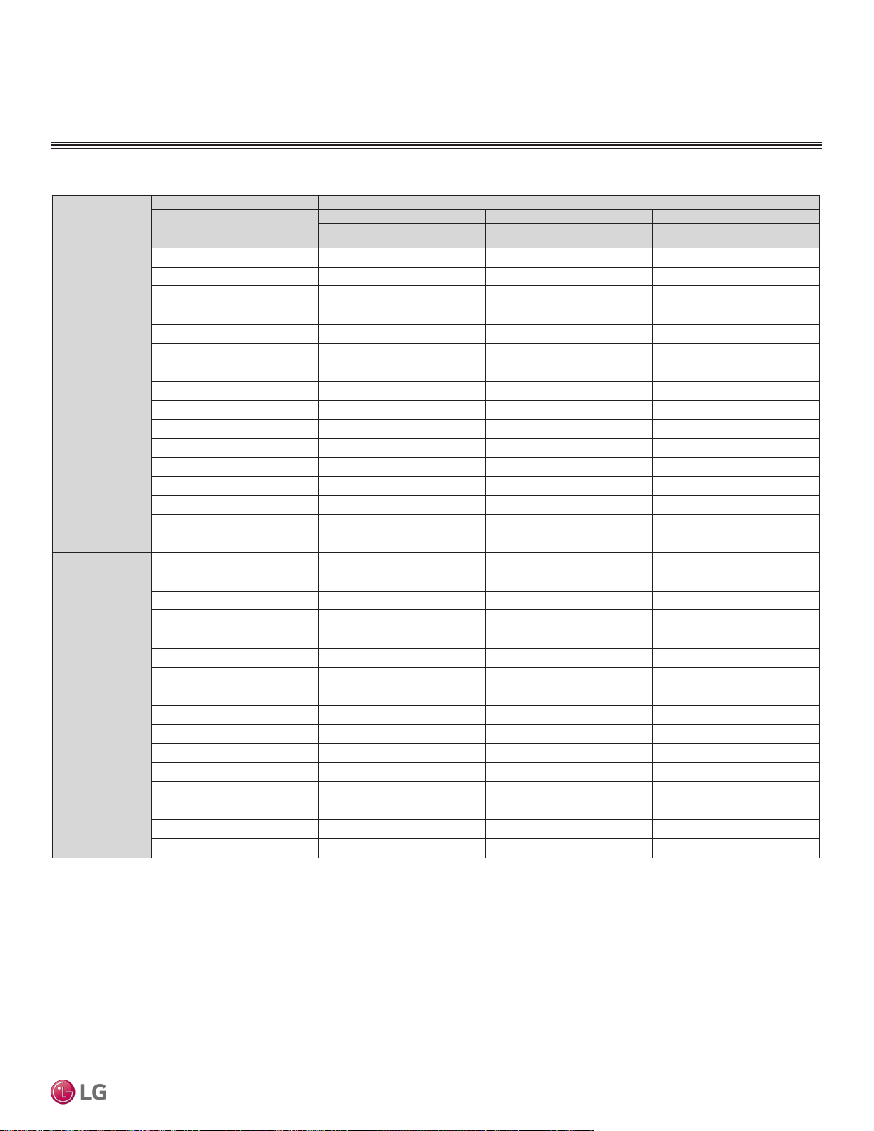
Model No. /
Nominal Capacity of
Indoor Unit
(Btu/h)
Outdoor Air Temp. Indoor Air Temp. °F DB
°F DB °F WB
61 64 68 70 72 75
TC TC TC TC TC TC
LCN128HV4
12,000
0 -0.4 7.10 7.00 6.93 6.90 6.80 6.50
5 4.5 8.00 7.90 7.83 7.80 7.70 7.40
10 9 8.90 8.80 8.73 8.70 8.60 8.30
17 15 10.10 10.00 9.93 9.90 9.80 9.48
20 19 10.55 10.45 10.38 10.35 10.25 9.90
25 23 11.30 11.20 11.13 11.10 11.00 10.60
30 28 11.95 11.85 11.78 11.75 11.65 11.30
35 32 12.60 12.50 12.43 12.40 12.30 12.00
40 36 13.18 13.08 13.02 12.98 12.88 12.58
45 41 13.77 13.67 13.60 13.57 13.47 13.17
47 43 14.00 13.90 13.83 13.80 13.70 13.40
50 46 14.23 14.13 14.06 14.03 13.93 13.59
55 51 14.60 14.50 14.43 14.40 14.30 13.90
60 56 14.60 14.50 14.43 14.40 14.30 13.96
63 59 14.60 14.50 14.43 14.40 14.30 14.00
68 64 14.60 14.50 14.43 14.40 14.30 14.06
LCN188HV4
18,000
0 -0.4 10.70 10.55 10.45 10.40 10.25 9.80
5 4.5 12.06 11.91 11.81 11.76 11.61 11.15
10 9 13.41 13.26 13.16 13.11 12.96 12.51
17 15 15.22 15.07 14.97 14.92 14.77 14.29
20 19 15.90 15.75 15.65 15.60 15.45 14.92
25 23 17.03 16.88 16.78 16.73 16.58 15.98
30 28 18.01 17.86 17.76 17.71 17.56 17.03
35 32 18.99 18.84 18.74 18.69 18.54 18.09
40 36 19.87 19.72 19.62 19.57 19.42 18.97
45 41 20.75 20.60 20.50 20.45 20.30 19.85
47 43 21.10 20.95 20.85 20.80 20.65 20.20
50 46 21.44 21.29 21.19 21.14 20.99 20.48
55 51 22.01 21.86 21.75 21.70 21.55 20.95
60 56 22.01 21.86 21.75 21.70 21.55 21.04
63 59 22.01 21.86 21.75 21.70 21.55 21.10
68 64 22.01 21.86 21.75 21.70 21.55 21.20
Heating Capacity Table
FOUR-WAY CEILING-CASSETTE INDOOR UNITS
TC = Total Capacity (kBtu/h).
Nominal capacity as rated 0 ft. above sea level and a 0 ft. level difference between outdoor and indoor units. Corresponding refrigerant piping length is accordance with standard length of each outdoor unit.
Nominal heating capacity rating obtained with air entering the indoor unit at 70ºF dry bulb (DB) and 60ºF wet bulb (WB), and outdoor ambient conditions of 47ºF dry bulb (DB) and 43ºF wet bulb (WB).
Table 70:Multi F Four-Way Ceiling-Cassette Indoor Units Heating Capacity Table.
CEILING-CASSETTE | 143
Four-Way Ceiling-Cassette
Due to our policy of continuous product innovation, some specications may change without notication.
©LG Electronics U.S.A., Inc., Englewood Cliffs, NJ. All rights reserved. “LG” is a registered trademark of LG Corp.
MULTI
F
MAX
MULTI
F
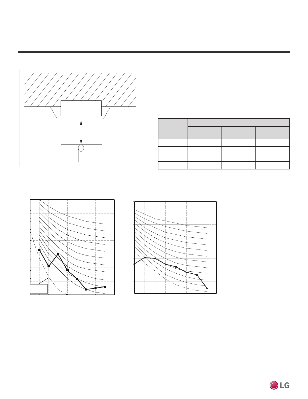
Acoustic Data
• Measurement taken 4.9′ away from the unit.
• Measurements taken with no attenuation and units operating at full
load normal operating condition.
• Sound level will vary depending on a range of factors such as
construction (acoustic absorption coefficient) of particular area in
which the equipment is installed.
• Sound power levels are measured in dB(A).
• Tested in anechoic chamber per ISO Standard 3745.
Figure 184:Sound Pressure Level Measurement Location.
Model No.
Sound Pressure Levels (dB[A]) (Cooling and Heating)
High Fan Speed
Medium Fan
Speed
Low Fan Speed
LMCN078HV 31 27 24
LCN098HV4 36 33 30
LCN128HV4 38 35 32
LCN188HV4 41 39 36
Table 71:Sound Pressure Levels (dB[A]).
Figure 185:LMCN078HV and LCN098HV4 Sound Pressure Level Diagrams.
4.9 ft.
Ceiling
Microphone
FOUR-WAY CEILING-CASSETTE INDOOR UNITS
10
20
30
40
50
60
70
80
90
63 125 250 500 1000 2000 4000 8000
Octave Band Center Frequency (Hz)
NC-15
NC-70
NC-65
NC-60
NC-55
NC-50
NC-45
NC-40
NC-35
NC-30
NC-25
NC-20
Sound Pressure Level (dB re 20uPa)
LCN098HV4
Octave Band Sound Pressure Level (dB re 20Pa)
Octave Band Center Frequency (Hz)
10
20
30
40
50
60
70
80
63 125 250 500 1000 2000 4000 8000
NC-15
NC-20
NC-25
NC-30
NC-35
NC-40
NC-45
NC-50
NC-55
NC-60
NC-65
Approximate
Hearing
Threshold
LMCN078HV
Due to our policy of continuous product innovation, some specications may change without notication.
©LG Electronics U.S.A., Inc., Englewood Cliffs, NJ. All rights reserved. “LG” is a registered trademark of LG Corp.
144 | CEILING-CASSETTE
Multi F and Multi F MAX Indoor Unit Engineering Manual
MULTI
F
MAX
MULTI
F
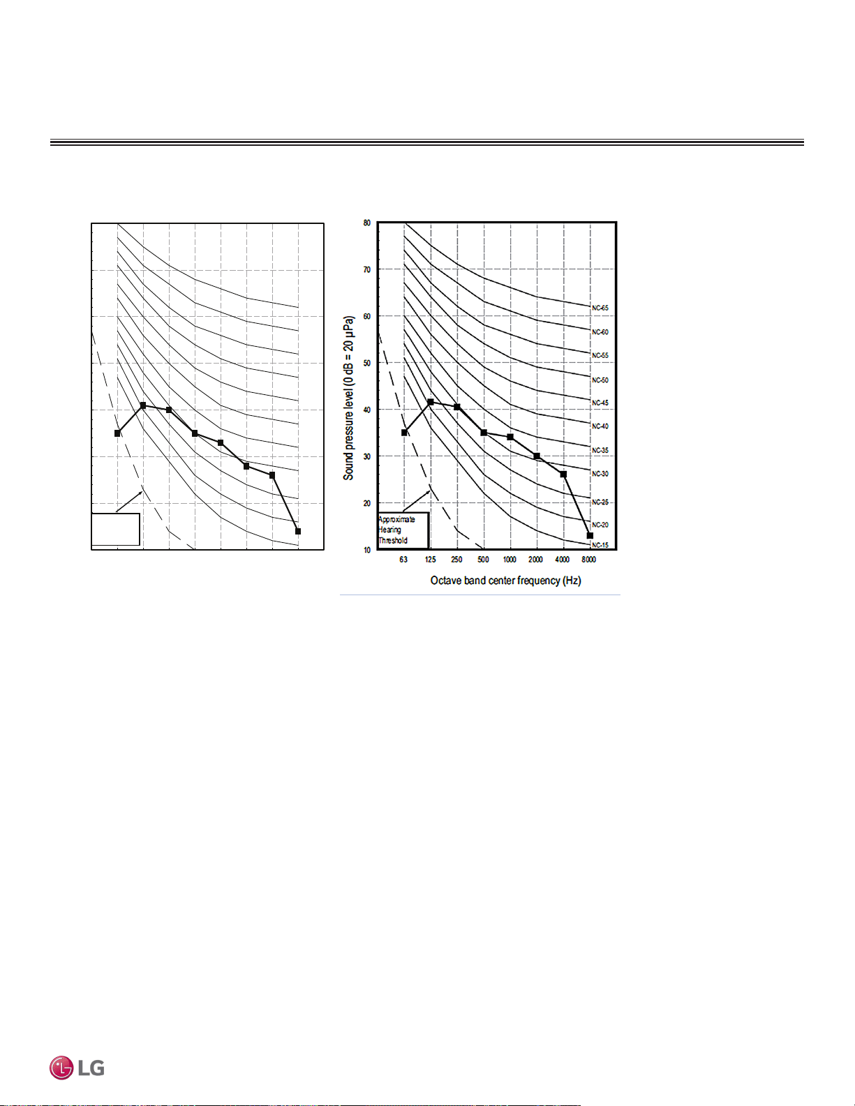
LCN188HV4
Acoustic Data
FOUR-WAY CEILING CASSETTE INDOOR UNITS
Figure 186:LCN128HV4 and LCN188HV4 Sound Pressure Level Diagrams.
Octave band center frequency (Hz)
Sound pressure level (0 dB = 20 µPa)
10
20
30
40
50
60
70
80
63 125 250 500 1000 2000 4000 8000
NC-15
NC-20
NC-25
NC-30
NC-35
NC-40
NC-45
NC-50
NC-55
NC-60
NC-65
Approximate
Hearing
Threshold
LCN128HV4
CEILING-CASSETTE | 145
Four-Way Ceiling-Cassette
Due to our policy of continuous product innovation, some specications may change without notication.
©LG Electronics U.S.A., Inc., Englewood Cliffs, NJ. All rights reserved. “LG” is a registered trademark of LG Corp.
MULTI
F
MAX
MULTI
F
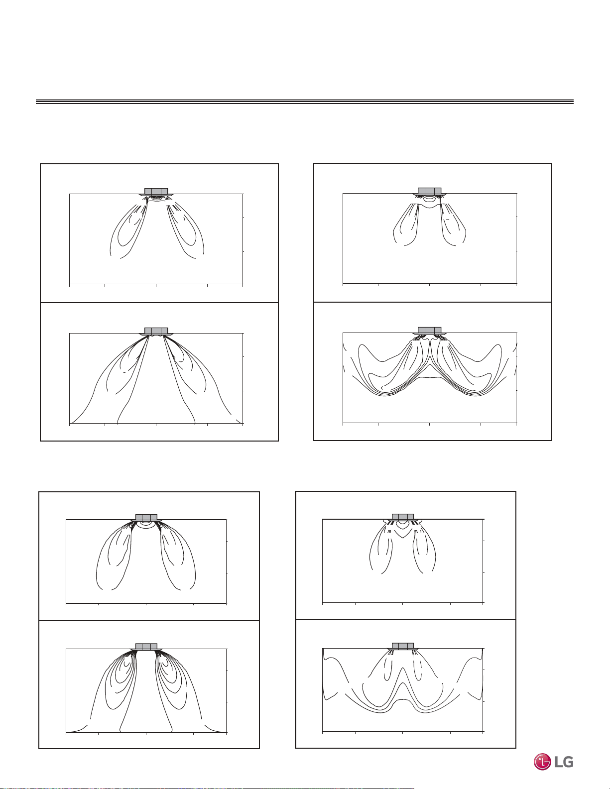
Air Velocity and Temperature Distribution
FOUR-WAY CEILING-CASSETTE INDOOR UNITS
Figure 187:LMCN078HV Air Velocity and Temperature Distribution Charts.
Figure 188:LCN098HV4 Air Velocity and Temperature Distribution Charts.
Cooling Heating
Discharge angle: 40°
Air velocity [ft/s]
Temperature [°F]
6.6
6.6
4.9
4.9
3.3
3.3
1.6
1.6
54
68
72
75
54
68
72
75
Discharge angle: 50°
Air velocity [ft/s]
Temperature [°F]
9191
8181
75
75
70
64
70
64
6.6
4.9
3.3
1.6
6.6
4.9
3.3
1.6
9f t
7f t
3f t
0f t
9f t
7f t
3f t
0f t
5f t5ft8f t8ft0f t
9f t
7f t
3f t
0f t
5f
t5
ft8f
t8
ft0f t
9f t
7f t
3f t
0f t
5f
t5
ft8f
t8
ft0f t
5f t5ft8f t8ft0f t
Cooling Heating
Discharge angle: 40°
Air velocity [ft/s]
Temperature [°F]
9ft
7ft
3ft
0ft
0ft
5ft5ft8ft8ft0ft
9ft
7ft
3ft
0ft
5f
t5
ft8f
t8
ft0ft
9ft
7ft
3ft
5ft5ft8ft8ft0ft
0ft
9ft
7ft
3ft
5f
t5
ft8f
t8
ft0ft
6.66.6
4.94.9
3.33.3
1.61.6
6464
6868
7272
7575
Discharge angle: 50°
Air velocity [ft/s]
Temperature [°F]
6.66.6
4.94.9
3.33.3
1.61.6
9191
8686
8181
7575
7070
Due to our policy of continuous product innovation, some specications may change without notication.
©LG Electronics U.S.A., Inc., Englewood Cliffs, NJ. All rights reserved. “LG” is a registered trademark of LG Corp.
146 | CEILING-CASSETTE
Multi F and Multi F MAX Indoor Unit Engineering Manual
MULTI
F
MAX
MULTI
F
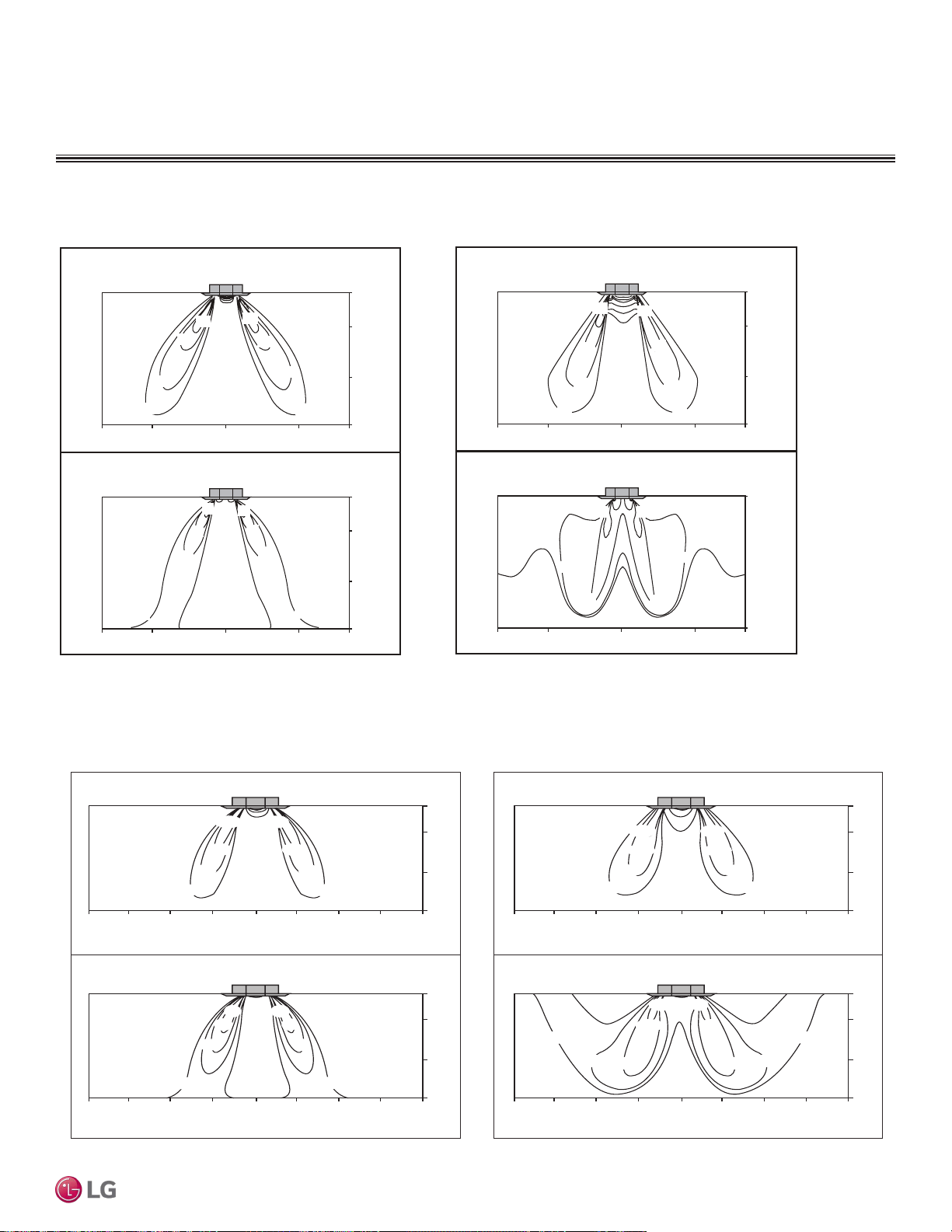
Figure 189:LCN128HV4 Air Velocity and Temperature Distribution Charts.
Figure 190:LCN188HV4 Air Velocity and Temperature Distribution Charts.
Cooling Heating
9ft
7ft
3ft
0ft
13ft10ft10ft7ft7ft3ft0ft3ft13ft
9ft
7ft
3ft
0ft
13ft10ft10ft7ft7ft3ft0ft3ft13ft
Air velocity [ft/s]
Temperature [°F]
91 91
86 86
81 81
75 75
70 70
6.6 6.6
4.9 4.9
3.3 3.3
1.6 1.6
Air velocity [ft/s]
9ft
7ft
3ft
0ft
13ft10ft10ft 7ft7ft3ft0ft3ft13ft
9ft
7ft
3ft
0ft
13ft10ft10ft 7ft7ft3ft0ft3ft13ft
Temperature [°F]
6.6
64 64
68 68
72 72
75 75
6.6
4.9 4.9
3.3 3.3
1.6 1.6
Discharge angle : 40° Discharge angle : 50°
Air Velocity and Temperature Distribution
FOUR-WAY CEILING CASSETTE INDOOR UNITS
Cooling Heating
Discharge angle: 40°
Air velocity [ft/s]
Temperature [°F]
9ft
7ft
3ft
0ft
0ft
5ft5ft8ft8ft0ft
9ft
7ft
3ft
0ft
5f
t5ft8ft8ft0ft
9ft
7ft
3ft
5ft5ft8ft8ft0ft
0ft
9ft
7ft
3ft
5f
t5ft8ft8ft0ft
Discharge angle: 50°
Air velocity [ft/s]
Temperature [°F]
6.6
6.6
4.6
4.6
3.3
3.3
1.6
1.6
9191
81
81
75
75
75
6.6
6.6
4.6
4.6
3.3
3.3
1.6
1.6
64
64
68
72
72
68
75
CEILING-CASSETTE | 147
Four-Way Ceiling-Cassette
Due to our policy of continuous product innovation, some specications may change without notication.
©LG Electronics U.S.A., Inc., Englewood Cliffs, NJ. All rights reserved. “LG” is a registered trademark of LG Corp.
MULTI
F
MAX
MULTI
F
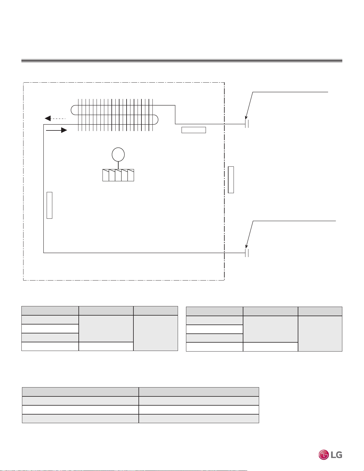
Refrigerant Flow Diagram
Figure 191:Multi F Four-Way Ceiling-Cassette Indoor Unit Refrigerant Flow Diagram.
Table 72:Multi F Four-Way Ceiling-Cassette Indoor Unit Refrigerant Pipe
Sizes.
Model No. Vapor (inch) Liquid (inch)
LMCN078HV
Ø3/8
Ø1/4
LCN098HV4
LCN128HV4
LCN188HV4 Ø1/2
Table 73:Multi F Four-Way Ceiling-Cassette Indoor Unit Refrigerant Pipe
Connections.
Description (Based on Cooling Mode) PCB Connector
Indoor Air Temperature Thermistor CN-ROOM
Evaporator Inlet Temperature Thermistor CN-PIPE/IN
Evaporator Outlet Temperature Thermistor CN-PIPE/OUT
FOUR-WAY CEILING-CASSETTE INDOOR UNITS
Heat exchanger
Gas pipe connection port
(flare connection)
Liquid pipe connection port
(flare connection)
Turbo fan
M
Cooling
Heating
Indoor Air
Temperature Thermistor
Evaporator Inlet
Temperature Thermistor
Evaporator Outlet
Temperature Thermistor
Table 74:Multi F Four-Way Ceiling-Cassette Indoor Unit Thermistor Details.
Model No. Vapor (inch) Liquid (inch)
LMCN078HV
Ø3/8
Ø1/4
LCN098HV4
LCN128HV4
LCN188HV4 Ø1/2
Due to our policy of continuous product innovation, some specications may change without notication.
©LG Electronics U.S.A., Inc., Englewood Cliffs, NJ. All rights reserved. “LG” is a registered trademark of LG Corp.
148 | CEILING-CASSETTE
Multi F and Multi F MAX Indoor Unit Engineering Manual
MULTI
F
MAX
MULTI
F
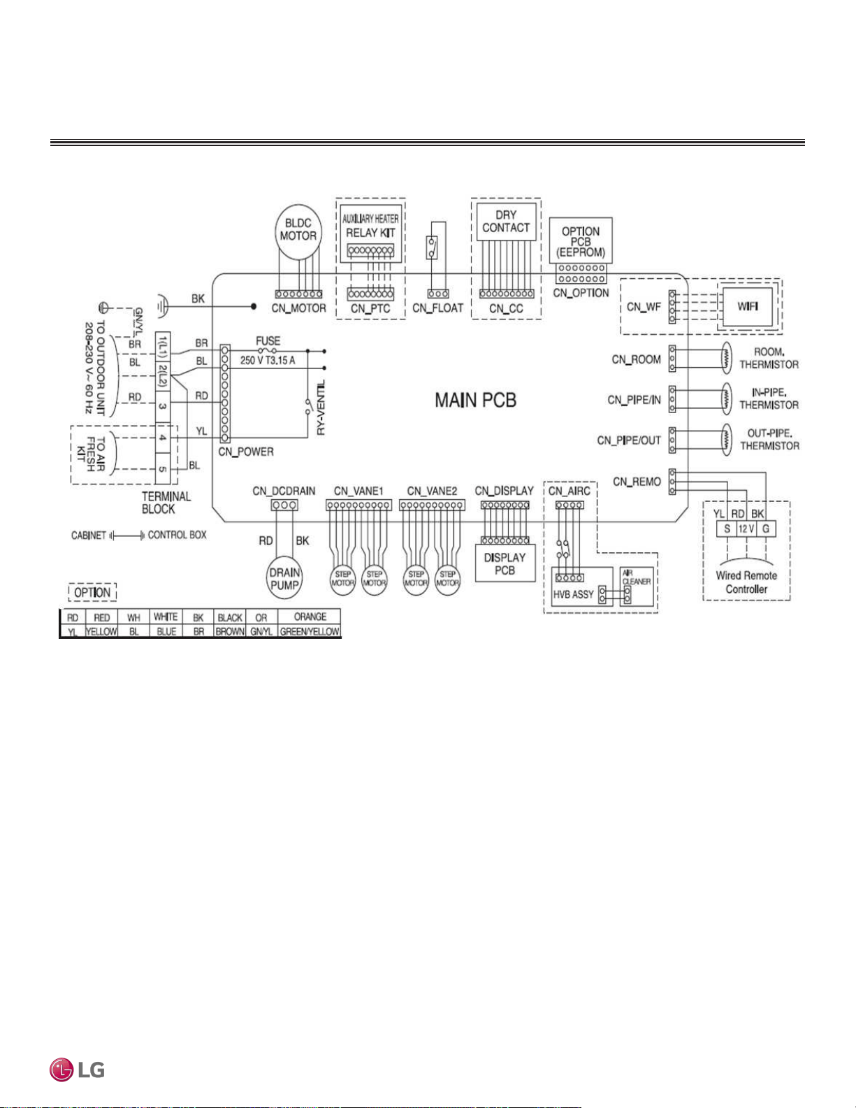
Wiring Diagram
Figure 192:Multi F Four-Way Ceiling-Cassette Indoor Unit Wiring Diagram.
FOUR-WAY CEILING CASSETTE INDOOR UNITS
CEILING-CASSETTE | 149
Four-Way Ceiling-Cassette
Due to our policy of continuous product innovation, some specications may change without notication.
©LG Electronics U.S.A., Inc., Englewood Cliffs, NJ. All rights reserved. “LG” is a registered trademark of LG Corp.
MULTI
F
MAX
MULTI
F
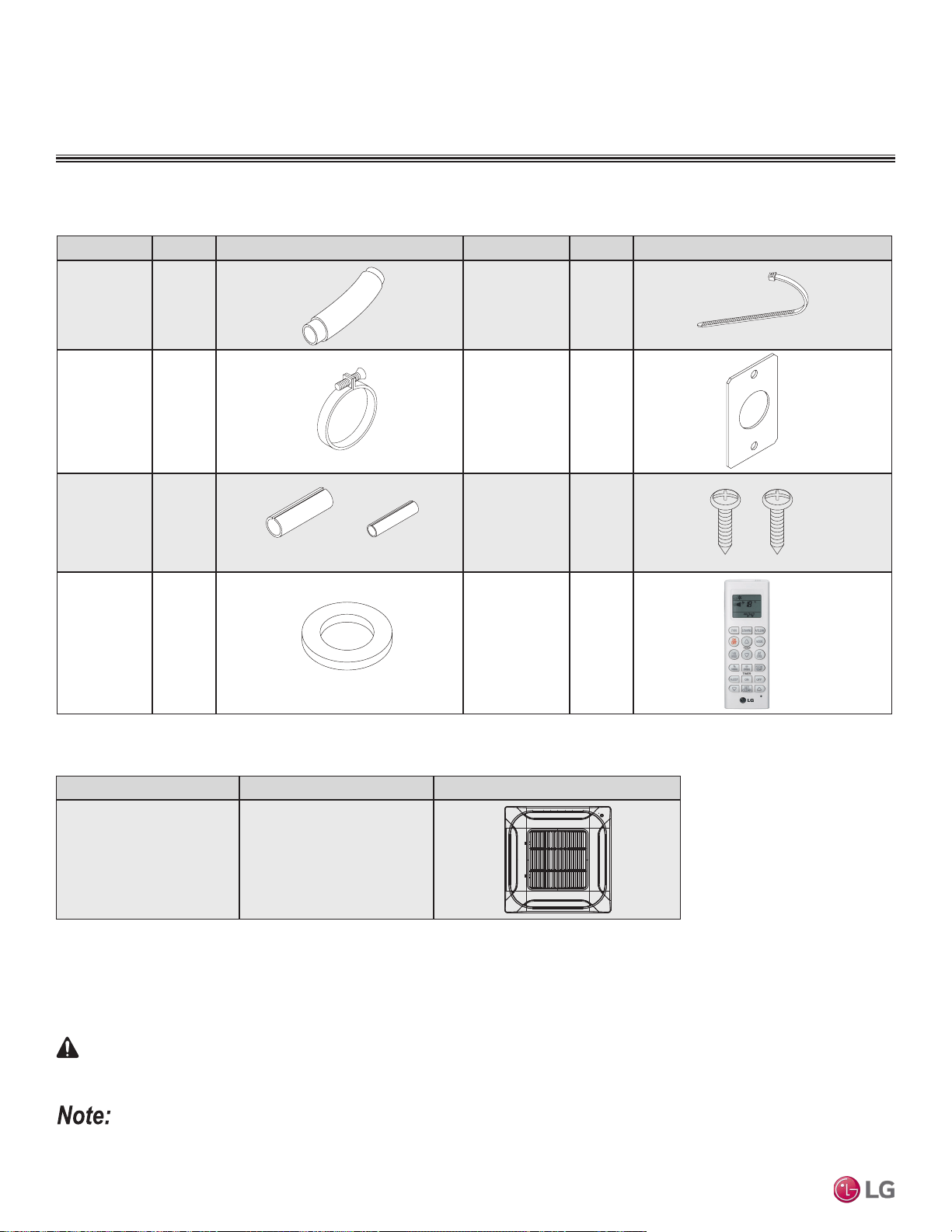
FOUR-WAY CEILING-CASSETTE INDOOR UNITS
Factory Supplied Parts and Materials
Factory Supplied Parts
Factory Supplied Materials
• Installation Guide (template)
• Owner’s Manual
• Installation Manual
Table 75: Parts Table.
Part Quantity Image Part Quantity Image
Drain Hose One (1) Zip Ties Four (4)
Metal
Clamp
Two (2)
Conduit
Bracket
One (1)
Insulation
for Fittings
One (1)
Set
M4 Screws Two (2)
Washer for
Hanging
Bracket
Eight (8)
Wireless Handheld
Controller with
Holder
(AKB73757604)
1
One (1)
For Vapor Piping For Liquid Piping
Required Tools
• Level
• Screwdriver
• Electric drill
• Hole core drill
• Flaring tool set
• Torque wrenches
• Hexagonal wrench
• Gas-leak detector
• Thermometer
1
Wireless Handheld Controller for the four-way ceiling cassette indoor units is also referenced by Model No. PQWRHQ0FDB.
Table 76:Required Accessory Table.
Part Quantity Image
Grille Kit
(PT-QCHW0)
One (1)
WARNING
Installation work must be performed by trained personnel and in accordance with national wiring standards and all local or other applicable codes.
Improper installation can result in re, electric shock, physical injury, or death.
Read all instructions before installing this product. Become familiar with the unit’s components and connections, and the order of installation. Incorrect
installation can degrade or prevent proper operation.
Due to our policy of continuous product innovation, some specications may change without notication.
©LG Electronics U.S.A., Inc., Englewood Cliffs, NJ. All rights reserved. “LG” is a registered trademark of LG Corp.
150 | CEILING-CASSETTE
Multi F and Multi F MAX Indoor Unit Engineering Manual
MULTI
F
MAX
MULTI
F
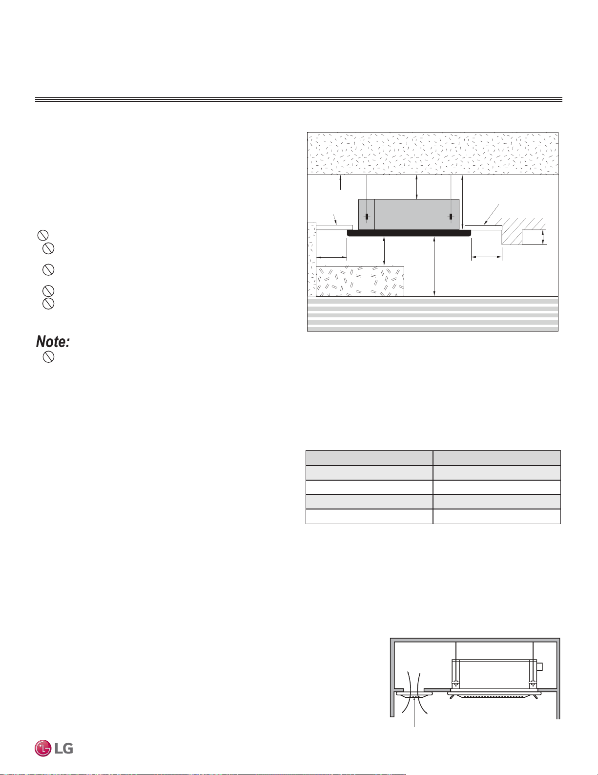
FOUR-WAY CEILING CASSETTE INDOOR UNITS
Installation and Best Layout Practices
Selecting the Best Location
Do’s
• Place the unit where air circulation will not be blocked.
• Place the unit where drainage can be obtained easily.
• Place the unit where noise prevention is taken into consideration.
• Ensure there is sufcient strength to bear the load of the indoor unit.
• Ensure there is sufficient maintenance space.
• Locate the indoor unit in a location that is level, and where it can
be easily connected to the outdoor unit / branch distribution unit.
Ceiling
Ceiling Tile
Ceiling Tile
Floor
≥13/32
≥11-13/16 inches
H = 6 feet to 12 feet
≥39-3/8 inches
≥19-11/16
≥19-11/16
≤11-13/16 inches
inches
inches
inches
Figure 193:Indoor Unit Clearance Requirements.
Installing in a High or Dropped Ceiling
High or dropped ceilings, often found in commercial buildings and
offices, will cause a wide temperature differentiation. To counter-
measure:
• Change the indoor unit mode selection to allow for higher ceilings
(see table).
• Install an air circulator.
• Set the air discharge outlet so that heated air flows in a downward
direction.
• Use a dual door system to protect the building gate or exit.
Installing in an Area Exposed to Unconditioned Air
In some installation applications, areas (floors, walls) in some rooms will be exposed to unconditioned air (room will be above or next to an
unheated garage or storeroom). To countermeasure:
• Verify that carpet is or will be installed (carpet will increase the temperature by three (3) degrees).
• Add insulation between the floor joists.
• Install radiant heat or another type of heating system to the floor.
Ceiling Height Mode Selection
≤7-1/2 feet Low Ceiling
7-1/2 feet to 8-7/8 feet Standard
8-7/8 feet to 10-3/16 feet High Ceiling
10-3/16 feet to 11-13/16 feet Very High Ceiling
Table 77:Indoor Unit High Ceiling Mode Selection Options.
Installing in an Area with High Humidity Levels
If the environment is prone to humidity levels of 80% or more (near the ocean, lakes, etc.) or
where steam could collect in the plenum:
• Install additional insulation to the indoor unit (glass wool insulation >13/32 inches thick).
• Install additional insulation to the refrigerant piping (insulation >13/16 inches thick).
• Seal all gaps between the indoor unit and the ceiling tiles (make the area air tight) so that
humidity does not transfer from the plenum to the conditioned space. Also, add a ceiling
grille for ventilation.
Ventilation Grille
Figure 194:Installing in a Highly Humid Location.
Don’ts
• Do not install the unit near a heat or steam source, or where
considerable amounts of oil, iron powder, or flour are used.
• Do not install the unit where sulfuric acid and flammable or cor-
rosive gases are generated, vented into, or stored.
• Do not install the unit near high-frequency generators.
• Do not install the unit near a doorway.
The unit will be damaged, will malfunction, and/or will not
operate as designed if installed in any of the conditions listed.
•
Indoor units (IDUs) must not be placed in an environment where the IDUs will be exposed to harmful volatile organic compounds (VOCs)
or in environments where there is improper air make up or supply or inadequate ventilation. If there are concerns about VOCs in the envi-
ronment where the IDUs are installed, proper air make up or supply and/or adequate ventilation must be provided. Additionally, in buildings
where IDUs will be exposed to VOCs, consider a third party factory-applied epoxy coating to the fan coils for each IDU where the entire coil
is dipped, not sprayed.
• If the unit is installed near a body of water, the installation parts are at risk of corroding. Appropriate anti-corrosion methods must be taken
for the unit and all installation parts.
CEILING-CASSETTE | 151
Four-Way Ceiling-Cassette
Due to our policy of continuous product innovation, some specications may change without notication.
©LG Electronics U.S.A., Inc., Englewood Cliffs, NJ. All rights reserved. “LG” is a registered trademark of LG Corp.
MULTI
F
MAX
MULTI
F
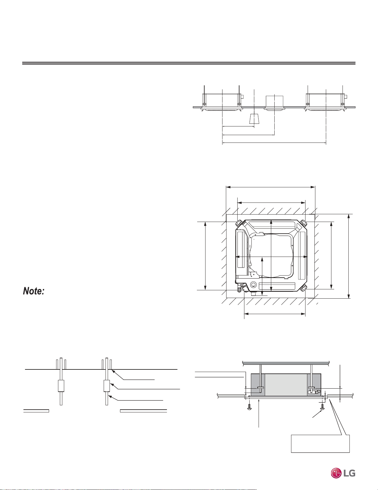
Ceiling
Anchor
Long nut or turnbuckle
Suspension bolt
Ceiling tile
Install the four screws
at the location marked on the
template
Installation Guide
(template)
Ceiling tile
7-3/32 inches
Ceiling tile
Ceiling
Leave 1-9/16 inches of the bolt
beneath the bracket
Open the ceiling tiles that are
along the outside edge of the
installation guide.
Indoor Unit
Leave a space of 1-3/16 inches ± 1/8 inches
between the bottom of the indoor unit and the
ceiling
Installing Multiple Indoor Units in One Area
Ensure there is enough space between indoor units, lighting fixtures,
and ventilation fans / systems.
FOUR-WAY CEILING-CASSETTE INDOOR UNITS
>59-1/16 inches
Indoor unit
Lighting
Ventilator
Indoor unit
>78-25/32 inches
>118-5/32 inches
Figure 195:Installing Multiple Indoor Units.
Preparing the Installation Area
1. Installation guide (template) depicts the exact dimensions
necessary for the ceiling opening.
2. Choose the location for the indoor unit, and then mark where the
bolts, refrigerant piping, and drain hose must be. Suspension bolt
angle must account for drain direction.
3. Drill holes for the bolts. Use either a W 3/8 inch or a M10 size
bolt.
23-1/16 inches ~ 26 inches (Ceiling Opening)
20-3/8 inches
18-5/32 inches
20-3/8 inches
23-1/16 inches ~ 26 inches (Ceiling Opening)
20-19/32 inches
22-15/32 inches
Unit Size
22-15/32 inches
Unit Size
12-9/16 inches
Figure 196:Ceiling Opening Dimensions and Bolt Locations.
Figure 197:Installing the Hanging Bolt in the Ceiling.
For easier installation, attach the accessories (except for the
decoration panel) before hanging the indoor unit.
Figure 198:Installation Diagram.
Installation and Best Layout Practices
Preparing the Installation Area and Hanging the Indoor Unit Frame
Due to our policy of continuous product innovation, some specications may change without notication.
©LG Electronics U.S.A., Inc., Englewood Cliffs, NJ. All rights reserved. “LG” is a registered trademark of LG Corp.
152 | CEILING-CASSETTE
Multi F and Multi F MAX Indoor Unit Engineering Manual
MULTI
F
MAX
MULTI
F
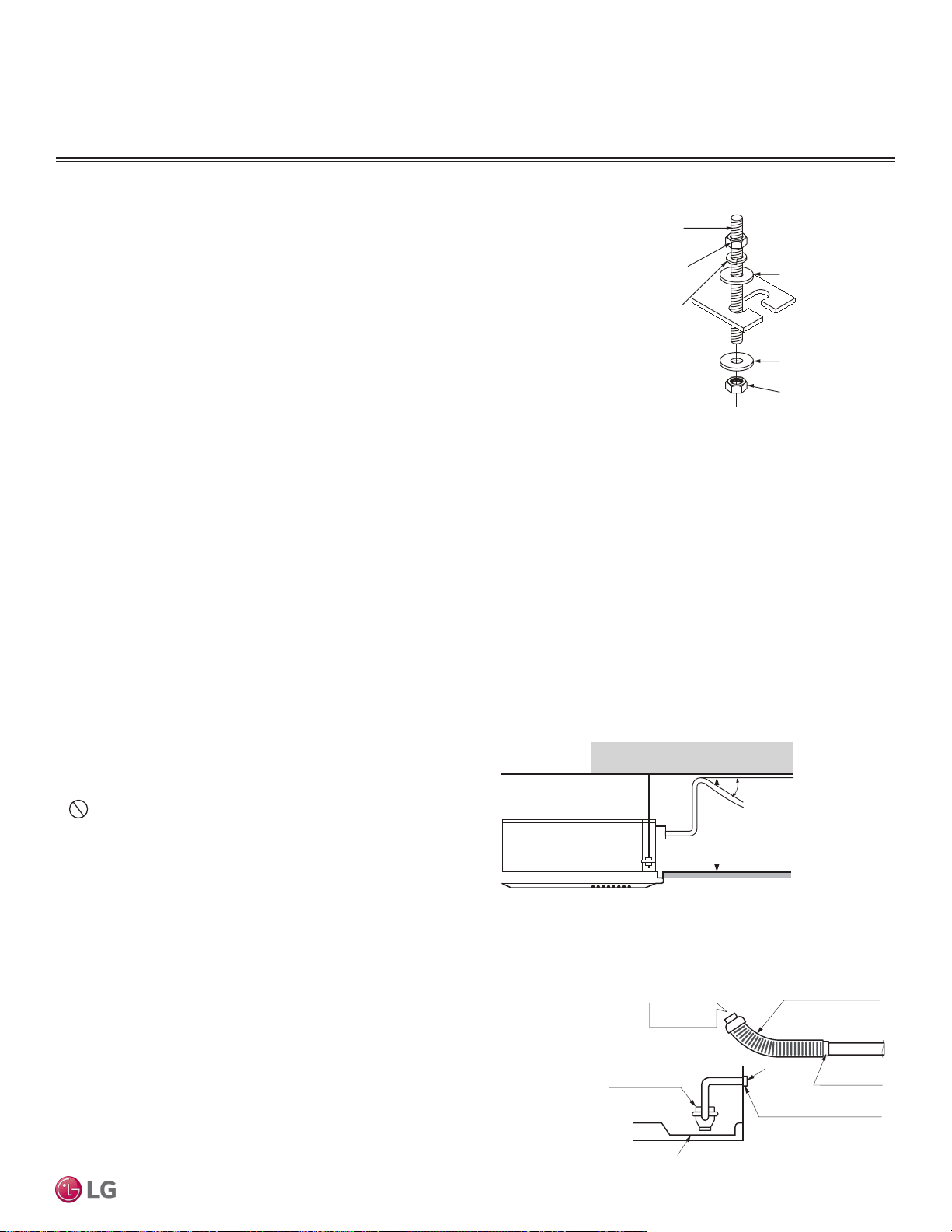
Figure 201:Checking the Drain Pump.
For Existing Ceilings
1. Use anchors when installing the indoor unit in an existing ceiling.
2. Ceiling height is shown on the side of the installation guide (template). Adjust the height of the unit accordingly. Adjust the clearance
before hanging the indoor unit.
3. Remove the temporary washer plate and position the indoor unit hanger brackets on the bolts. Secure with nuts and washers on the top
and bottom of the hanger brackets.
4. Ceiling-cassette indoor units are equipped with a built-in drain pump and float switch, therefore, the unit must be installed horizontally or
condensate will drip out and cause product malfunction. Measure the unit at each corner to verify that it is level.
5. Remove the installation guide (template).
For New Ceilings
1. Use a sunken insert, a sunken anchor, or any other field-supplied part to reinforce the
ceiling so that it can bear the weight of the indoor unit. Use a temporary washer plate
to more easily set up the unit suspension location.
2. Ceiling height is shown on the side of the installation guide (template). Adjust the
height of the unit accordingly. Adjust the clearance before hanging the indoor unit.
3. Refer to the installation guide (template) for the dimensions to the ceiling opening.
Match the center of the indoor unit (labeled) to the center indicated on the installation
guide.
4. Align the installation guide (template) with the label attached to the unit (affixing the
template to the unit if desired) to properly place the unit.
5. Remove the temporary washer plate and position the indoor unit hanger brackets
on the bolts. Secure with nuts and washers on the top and bottom of the hanger
brackets.
6. Ceiling-cassette indoor units are equipped with a built-in drain pump and float switch, therefore, the unit must be installed horizontally or
condensate will drip out and cause product malfunction. Measure the unit at each corner to verify that it is level.
7. Remove the installation guide (template).
Installation and Best Layout Practices
FOUR-WAY CEILING CASSETTE INDOOR UNITS
Flat washer for M10
(field supplied)
Flat washer for M10
(field supplied)
Hanging bolt
(W3/8 or M10)
Nut
(W3/8 or M10)
Nut
(W3/8 or M10)
Spring washer
(M10)
Figure 199:Hanging the Indoor Unit.
Installing the Drain System
• Drain piping must have downward gradient of at least 1/50 to
1/100; to prevent reverse flow, slope must not be straight up and
down.
•
Do not damage the drain port on the indoor unit when connect-
ing the field-supplied drain piping.
• Drain piping specifications:
- Indoor Unit Drain Connection: 1-1/4 inch outside diameter.
- Field-Supplied Drain Piping: Polyvinyl chloride piping with 1-inch
inside diameter and pipe fittings.
Pour Water
Drain Pump
Drain Pan
Flexible drain hose
(accessory)
Field-Installed
Drain Piping
Glue the Joint
Drain
Port
Drain Hose Connection
Use the clip (accessory)
Checking the Drain Pump
The unit uses a drain pump to remove condensate. The pump must be tested before the
system operates.
• Connect flexible drain hose to the field-installed drain piping; leave it as is until the test
is complete.
• Pour water into the flexible drain hose and check for leaks.
• After power wiring installation is complete, operate the drain pump to see if it sounds
and functions properly.
• After the test is complete, connect the flexible drain hose to the indoor unit drain port.
Figure 200:Indoor Unit Drain Piping.
1/50~
1/100
<27-1/2 inches (7~12MBh)
<31-1/2 inches (18MBh)
CEILING-CASSETTE | 153
Four-Way Ceiling-Cassette
Due to our policy of continuous product innovation, some specications may change without notication.
©LG Electronics U.S.A., Inc., Englewood Cliffs, NJ. All rights reserved. “LG” is a registered trademark of LG Corp.
MULTI
F
MAX
MULTI
F
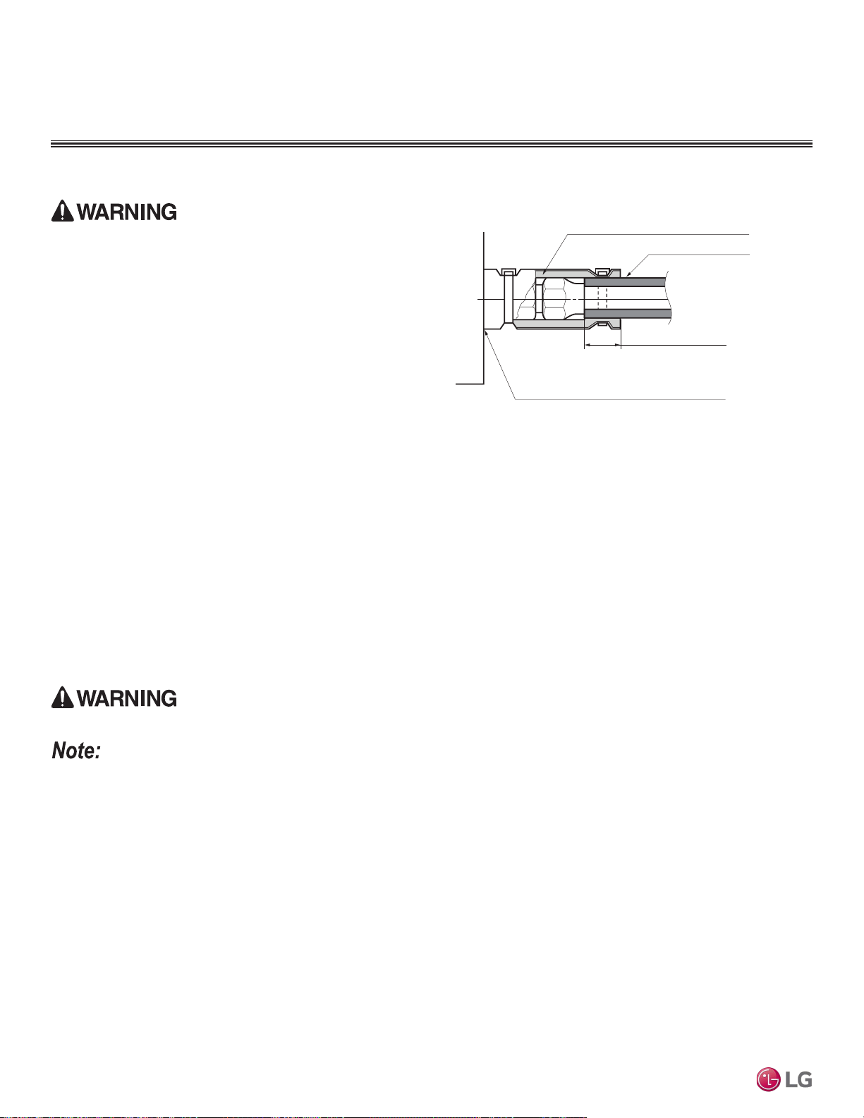
Power Wiring / Communications Cable Guidelines
FOUR-WAY CEILING-CASSETTE INDOOR UNITS
Installation and Best Layout Practices
• Follow manufacturer’s circuit diagrams in the technical manuals.
• Confirm power source specifications.
• Confirm that the electrical capacity is sufficient.
• Starting current must be maintained ±10 percent of the rated current marked on the outdoor unit name plate.
• Confirm cable thickness specifications.
• It is required that a circuit breaker is installed, especially if conditions could become wet or moist.
• Include a disconnect in the power wiring system, add an air gap contact separation of at least 1/8 inch in each active (phase) conductor.
Refrigerant Piping Insulation
Field-installed vapor and liquid refrigerant piping lines must be
properly and completely covered in insulation (up to the indoor unit
piping connections). Any exposed piping will generate condensate or
will cause burns if touched. Insulation for this field-installed refriger-
ant piping must have a minimum heat resistance of 248°F.
Drain Piping Insulation
Drain piping must have insulation a minimum of 7/32 inches thick.
Installing the Insulation
1. Overlap the insulation at the connection of the field-installed piping and the indoor unit piping. Tape together so that no gaps exist.
2. Secure insulation to the rear piping housing section with vinyl tape.
3. Bundle the piping and drain hose with tape where they meet at the back of the indoor unit frame. Position the drain hose at the bottom of
the bundle (positioning the drain hose at the top of the bundle will cause the drain pan to overflow inside the indoor unit).
Figure 202:Insulating the Piping.
Ensure no gaps are present.
Overlap the Insulation at the
Connection
Insulation for Refrigerant Piping
(Field-Supplied)
Insulation for Field-Installed Piping
(Field-Supplied)
Insulating the Refrigerant and Drain Piping
Ensure all piping is insulated. Exposed piping can cause burns if touched.
Loose wiring will cause unit to malfunction, overheat, and catch re, resulting in severe injury or death.
• Terminal screws will become loose during transport. Properly tighten the terminal connections during installation.
A voltage drop will cause the following problems:
• Magnetic switch vibration, fuse breaks, or disturbance to the normal function of an overload protection device.
• Compressor will not receive the proper starting current.
Due to our policy of continuous product innovation, some specications may change without notication.
©LG Electronics U.S.A., Inc., Englewood Cliffs, NJ. All rights reserved. “LG” is a registered trademark of LG Corp.
154 | CEILING-CASSETTE
Multi F and Multi F MAX Indoor Unit Engineering Manual
MULTI
F
MAX
MULTI
F
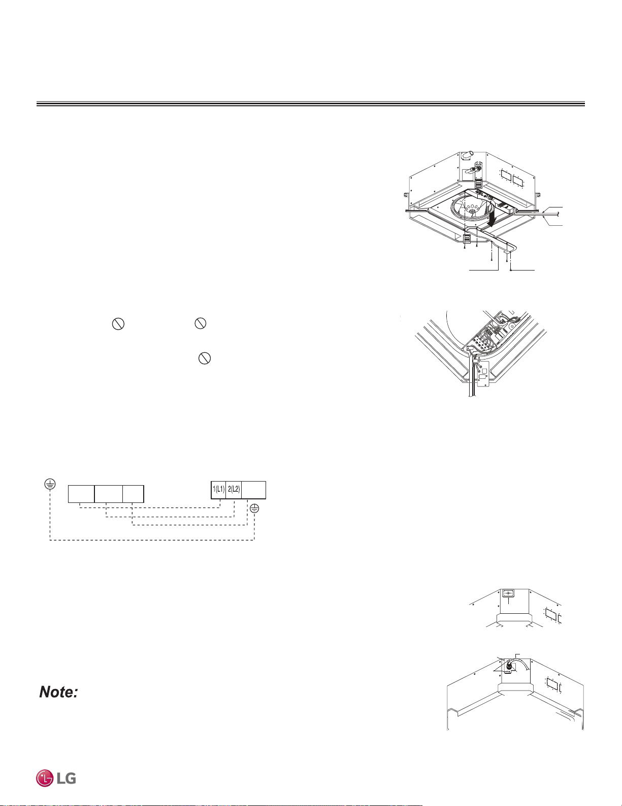
Wiring / Cable Connections
Power Wiring
Wired
Controller
Cable
Control Box Cover
Control Box
Cover Screws
Connecting the Power Wiring and
Communications Cable
1. To access the terminal block, open the control box cover.
2. Insert the power wiring / communications cable from the outdoor unit or branch
distribution unit (Multi F MAX systems only) through the sides of the indoor unit and
control box. Pass the wiring through the designated access holes to prevent dam-
age. To prevent electromagnetic interference and product malfunction, leave a space
between the power wiring and communications cable outside of the indoor unit.
3. Connect each wire to its appropriate terminal on the indoor unit control board. Verify
that the color and terminal numbers from the outdoor unit or branch distribution unit
(Multi F MAX systems only) wiring match the color and terminal numbers on the
indoor unit.
4. Neatly arrange power wiring / communications cable and secure with the appropriate
cable restraint.
When clamping, do not apply force to the wiring connec-
tions.
5. Firmly reattach the control box cover. Do not catch the wiring in the electric box
cover and make sure the cover firmly closes.
6. Fill in any gaps around the wiring access holes with sealant to prevent foreign
particles from entering the indoor unit.
Figure 203:Power Wiring and Communications
Cable Connection Access.
Figure 204:Simplied View of Indoor Unit to Outdoor Unit / Branch
Distribution Unit Terminal Connections.
Installation and Best Layout Practices
FOUR-WAY CEILING CASSETTE INDOOR UNITS
Ceiling cassette 4-way _ 19
Rubber Stopper
Cable
Conduit
Screws
Conduit Bracket
Using a Conduit
1. Remove the rubber stopper on the indoor unit. Pass the power wiring / communications cable
through the conduit, the conduit mounting plate, and to / through the control panel of the indoor unit.
2. Tighten the conduit and the conduit mounting plate together.
3. Connect the power wiring / communications cable to the indoor unit terminal block.
4. Screw the conduit mounting plate to the indoor unit.
Figure 205:Using a Conduit.
If the distance between the outdoor unit and indoor unit is greater than 131 feet, connect the power
wiring and communications cable separately (i.e., a conduit cannot be used).
Indoor Unit Terminal Block
GND
Outdoor Unit Terminal Block or
Branch Distribution Unit Terminal Block
(Multi F MAX Systems Only)
GND
GRN / YLW
BR
BL
RD
3 or S
32(L2)1(L1)
CEILING-CASSETTE | 155
Four-Way Ceiling-Cassette
Due to our policy of continuous product innovation, some specications may change without notication.
©LG Electronics U.S.A., Inc., Englewood Cliffs, NJ. All rights reserved. “LG” is a registered trademark of LG Corp.
MULTI
F
MAX
MULTI
F
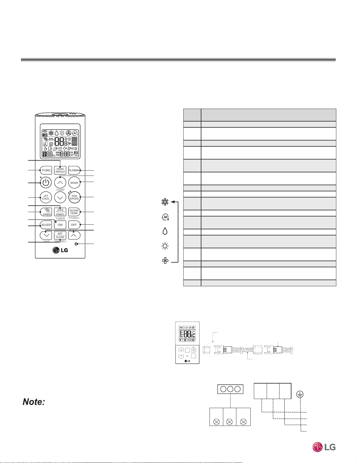
Figure 206:AKB73757604 Wireless Handheld Controller.
FOUR-WAY CEILING-CASSETTE INDOOR UNITS
Installation and Best Layout Practices
Controller Options
Four-way ceiling-concealed indoor units include a wireless handheld controller (AKB73757604)
1
, but optional LG-supplied wired controllers
are available.
Wireless Handheld Controller
Table 78:AKB73757604
1
Wireless Handheld Controller Functions.
2
Button
Label
Description
1 Vane Angle Button: Sets the angle to each vane.
2
Function Setting Button: Sets or clears auto clean, smart clean,
electric heater, or individual vane angle control functions.
3 On / Off Button: Turns the power on/off.
4
Jet Cool: Sets the unit to super high fan speed when in cooling
mode.
5
Left / Right Air Flow Button (optional): Sets the desired left / right
(horizontal) air flow direction.
6
Up / Down Air flow Button: Stops or starts louver movement, and
sets the desired air flow direction to up or down.
7 On Time Button: Sets the time when the operation begins.
8 Sleep Timer Button: Sets the sleep mode operation.
9
Set / Clear Button: Sets or cancels the timer, also sets the current
time.
10 Plasma Button: Starts or stops plasma-purification functions.
11
Room Temperature Setting Button: Raises or lowers temperature
setpoint in cooling and heating operation.
12 Operation mode selection button: Selects the operation mode.
13
Indoor Fan Speed Button: Changes the fan speed to one of four
choices: low, medium, high, and chaos.
14
Room Temperature Check Button: Displays / checks the room
temperature.
15 Off Timer button: Sets the time when the operation ends.
16
Time Setting (Up / Down) / Light Button: Sets the timer and
adjusts the brightness of the LED.
17 Reset Button: Resets the remote controller.
1
Wireless Handheld Controller for the four-way ceiling cassette indoor units is also referenced by Model
No. PQWRHQ0FDB.
2
Depending on the indoor unit model, some functions will not be supported or displayed.
2
3
4
1
5
9
7
6
8
10
12
13
14
15
1
7
16
11
Operation Mode Sequence
Cooling Mode
↓
Auto Mode/Changeover
↓
Dehumidification Mode
↓
Heating Mode
↓
Fan Mode
1(L) 2(N)
GND
3
BR
BL
RD
CN-REMO
To Wired Controller
YL
Comm.
(S)
RD
12V
Power
BK
Ground
Connections on
Wired Controller
Figure 207:PZCWRC1 LG Wired Remote Extension Cable.
Verify the connectors are properly inserted.
C/BOX Cable (Plug type)
Extension cable
To Indoor Unit
CN-REMO
Terminal
TEMP
FAN
SPEED
OPER
MODE
Figure 208:Wired Controller Connections on the Indoor Unit Terminal Block.
When using eld-supplied controller cable, make sure to connect
the yellow to yellow (communications wire), red to red (12V power
wire), and black to black (ground wire) terminals from the remote
controller to the indoor unit terminal blocks.
Wired Controller Connections
Controllers can connect to the indoor unit in one of two different
ways.
1. LG Wired Remote Extension Cable with Molex plug (PZC-
WRC1; sold separately) that connects to the CN-REMO
terminal on the indoor unit PCB.
2. Field-supplied controller cable that connects to the indoor unit
terminal block (must be at least UL2547 or UL1007, 22 AWG,
two-core, one-shield core, at least FT-6 rated if local electric
and building codes require plenum cable usage).
Due to our policy of continuous product innovation, some specications may change without notication.
©LG Electronics U.S.A., Inc., Englewood Cliffs, NJ. All rights reserved. “LG” is a registered trademark of LG Corp.
156 | CEILING-CASSETTE
Multi F and Multi F MAX Indoor Unit Engineering Manual
MULTI
F
MAX
MULTI
F
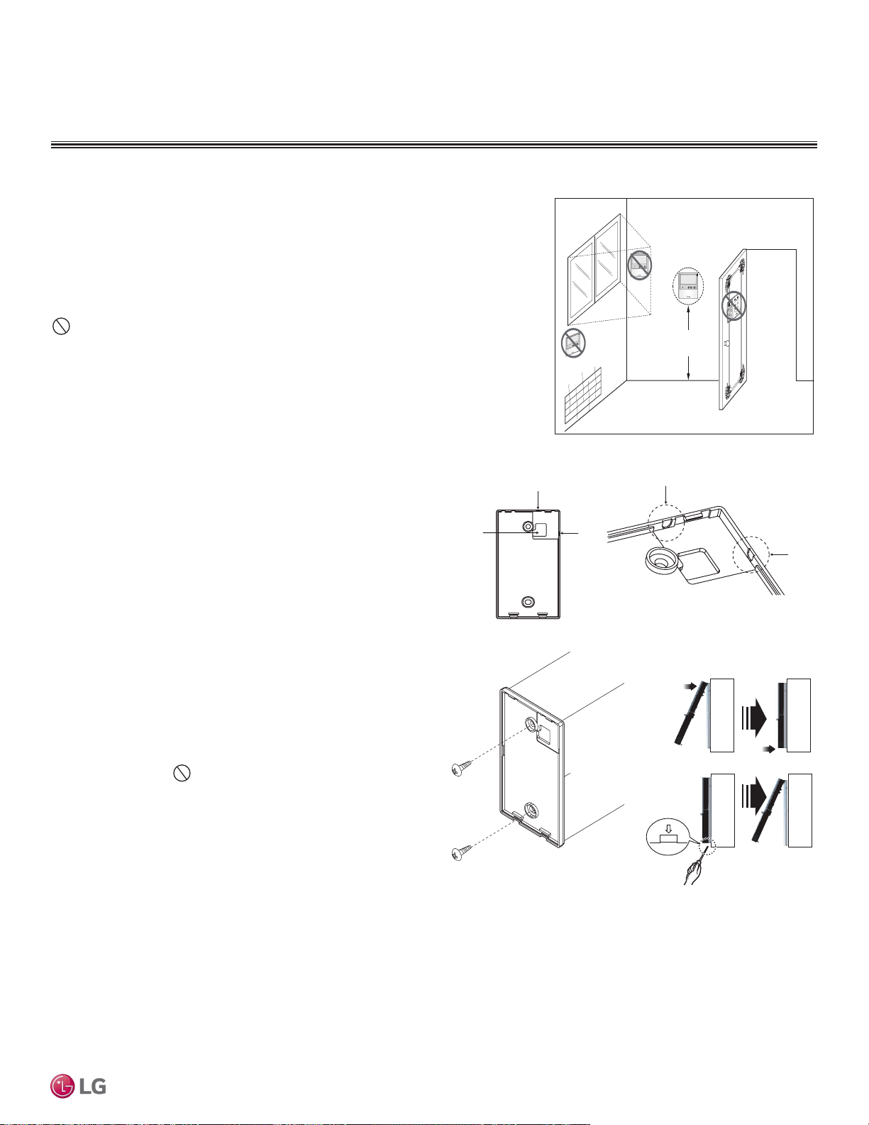
Installation and Best Layout Practices
FOUR-WAY CEILING CASSETTE INDOOR UNITS
4 to 5 feet
above the floor
NO
NO
NO
YES
Remote Controller
TEMP
Remote Controller
TEMP
Re
m
ot
e Co
n
t
roller
TEMP
Figure 209:Proper Location for the Wired Controller.
Wired Controller Placement
Wall indoor units can be used with various wired controllers (optional; sold separately).
Wired controllers include a sensor to detect room temperature. To maintain comfort
levels in the conditioned space, the wired controller must be installed in a location
away from direct sunlight, high humidity, and where it could be directly exposed to cold
air. Controller must be installed four (4) to five (5) feet above the floor where its display
can be read easily, in an area with good air circulation, and where it can detect an
average room temperature.
Do not install the remote controller where it can be impacted by the following:
• Drafts or dead spots behind doors and in corners
• Hot or cold air from ducts
• Radiant heat from sun or appliances
• Concealed pipes and chimneys
• Uncontrolled areas such as an outside wall behind the remote controller
Hanging the Wired Controller
1. The controller wiring / cable can be installed in one of three direc-
tions: top, back, or on the right side. If top or right side installation
is desired, remove cable guide grooves on the controller, and
then position wiring / cable on applicable side.
2. Choose and mark the area of installation, and then screw the wall
plate into place (using the provided parts). Install the controller
wall plate to fit the electrical box if one is present. Ensure that no
gaps exist between the wall plate and the wall itself.
3. Arrange wiring / cables so as not to interfere with the controller
circuitry. Position the wired controller on the wall plate. Snap into
place by pressing the bottom part of the wired controller onto
the wall plate. Make sure that no gaps exist between the wired
controller and the wall plate on all sides.
4. To remove wired controller from the wall plate, insert a screw-
driver into the two holes at the bottom. Twist screwdriver to
release controller. Do not damage the controller components
when removing.
Back
Top
Top
Right
Side
Right
Side
Wall Wall
Wall Wall
Installing the Controller
Removing the Controller
Figure 210:Removing the Cable Guide Grooves.
Figure 211:Attaching the Wall
Plate.
Figure 212:Installing / Removing
the Controller.
Assigning the Thermistor for Temperature Detection
Each indoor unit includes a return air thermistor assigned to sense the temperature. If a wired controller is installed, there is a choice of
sensing temperature with either the indoor unit return air thermistor or the thermistor in the wired controller. It is also an option to set both
thermistors to sense temperature so that indoor unit bases its operation on the first thermistor to reach the designated temperature differen-
tial. For applicable indoor units, an optional Remote Temperature Sensor can be used in lieu of the return air thermistor—either alone or in
conjunction with a wired controller thermistor as previously described.
CEILING-CASSETTE | 157
Four-Way Ceiling-Cassette
Due to our policy of continuous product innovation, some specications may change without notication.
©LG Electronics U.S.A., Inc., Englewood Cliffs, NJ. All rights reserved. “LG” is a registered trademark of LG Corp.
MULTI
F
MAX
MULTI
F
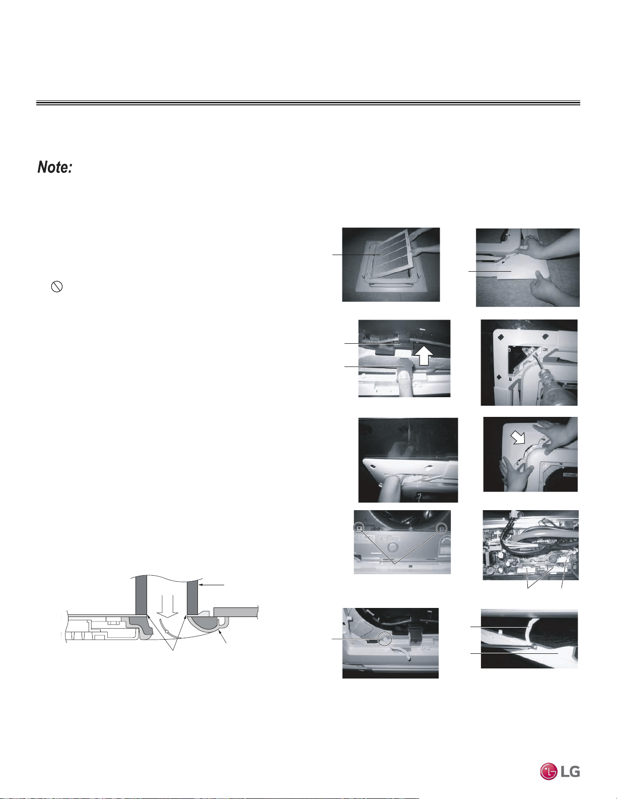
FOUR-WAY CEILING-CASSETTE INDOOR UNITS
Installation and Best Layout Practices
1. Remove the packaging, take out air inlet grille from the front
panel (1A), and then remove the corner covers of the panel (1B).
2. Attach the panel to the indoor frame by inserting the hooks as
shown (2).
3. Attach two screws on diagonal corners of each panel, but
do not tighten completely (3). Screws to attach the panel to
the indoor unit frame are factory-provided and can be found in
the shipping box.
4. Verify the panel is aligned with the ceiling. Adjust the height by
using the hanging bolts as shown (4).
5. Attach the corner covers (5).
6. Unscrew the control panel cover (6).
7. Connect the one display connector (CN-DISPLAY) and the two
vane control connectors (CN-VANE1, CN-VANE2) of the front
panel to the indoor unit PCB (7).
8. Close the control box cover. Attach the link on the front panel as
shown (8). The link is supplied in the front panel shipping package.
9. Attach the other side of the link on the filter guide of the air inlet
grille, then install the filter and the air inlet grille on the front panel
(9).
Grille
Corner
Cover
1A
1B
Indoor Unit
Decoration panel
Insulation should fit tightly so that
cool air does not leak
Ceiling
Tile
Decoration panel must be installed properly; cool air will leak from any gaps found between the indoor unit frame and the decoration panel,
which will cause condensation to generate.
Finalizing Indoor Unit Installation—
Installing the Decoration Panel
Hook clip
Hook
23
45
Screw
CN VANE 1,2
CN DISP
Link
Link
Filter
guide
67
8
9
Figure 213:Installing the Decoration Panel.
Figure 214:Ensure that no gaps are present between the
indoor unit frame and the decoration panel.
Due to our policy of continuous product innovation, some specications may change without notication.
©LG Electronics U.S.A., Inc., Englewood Cliffs, NJ. All rights reserved. “LG” is a registered trademark of LG Corp.
158 | CEILING-CASSETTE
Multi F and Multi F MAX Indoor Unit Engineering Manual
MULTI
F
MAX
MULTI
F

TWO-WAY
VERTICAL-HORIZONTAL
AIR HANDLING
INDOOR UNIT DATA
“Mechanical Specifications” on page 160
“General Data / Specifications” on page 161
“Dimensions” on page 162
“Cooling Capacity Table” on page 163
“Heating Capacity Table” on page 164
“External Static Pressure” on page 165
“Acoustic Data” on page 166
“Refrigerant Flow Diagram” on page 167
“Wiring Diagram” on page 168
“Factory Supplied Parts and Materials” on page 170
“Installation and Best Layout Practices” on page 171
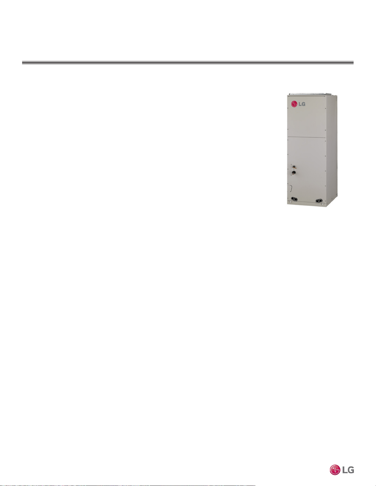
TWO-WAY VAHU INDOOR UNITS
Mechanical Specications and Features
Two-way Vertical-Horizontal Air
Handing Indoor Unit
General
All LG indoor units are factory assembled, wired, piped, and pro-
vided with a control circuit board, fan, and motor. Vertical-Horizontal
Air Handling units are designed for high-speed air volume against an
external static pressure up to 1.00″WG. Supply air opening is flanged
to accept field-installed ductwork that cannot exceed the external
static pressure limit of the unit.
Coil
Indoor unit coils are factory built and are comprised of aluminum ns
mechanically bonded to copper tubing. Each unit has a minimum of
two rows of coils, which are pressure tested at the factory. Each unit is
provided with a factory installed condensate drain pan below the coil.
Refrigerant System
System is designed for use with R410A refrigerant. The refrigeration
circuit is pressure-tested at the factory and shipped with a holding
charge of helium gas. Refrigerant pipe connections are 45° flare,
and all refrigerant lines from the outdoor unit to the indoor units must
be field insulated.
Electrical
Each indoor unit is designed to operate using 208–230/60/1 power
with voltage variances of ±10%.
Casing
The casing is designed to mount fully concealed behind a wall
or above a finished ceiling. Casing is manufactured of 22-gauge
precoated metal and finished with a high-gloss baked enamel finish.
Cold surfaces of the unit are covered internally with 1/2-inch polysty-
rene fiber insulation; inside surface of the pan assembly door access
panel is treated with 1/2-inch polystyrene fiber insulation, encapsu-
lated on both sides. The access panel is sealed along the edges with
reinforced foil-faced covering, all access panels also have gasket
seals to minimize air leaks.
The two-way vertical-horizontal air handling unit can operate in one
of two airflow configurations: the vertical (upflow) configuration or
horizontal (left) end discharge. Supply air is drawn from the top, and
there is a dedicated bottom vertical return. Unit is also designed to
accept an internal, optional LG electrical strip heater.
Fan Assembly and Control
The units have an integral fan assembly consisting of galvanized
steel housing and a forward
curve fan wheel. The fan
motor is a brushless digitally
controlled (BLDC) motor with
permanently lubricated and
sealed ball bearings. The fan
/ motor assembly is mounted
on vibration-attenuating rub-
ber grommets. Fan speed is
controlled using a micropro-
cessor-based direct digital
control algorithm. The indoor
fan has Low, Med, High, and
Auto settings for Cooling
mode; and has Low, Med,
High, and Auto settings for
Heating mode. Each of the
settings can be field-adjusted
from the factory setting (RPM
/ ESP). The Auto setting ad-
justs the fan speed to most
effectively achieve setpoint.
Filter Assembly
The unit includes a filter rack that can accept a field-supplied 16” x
20” x 1” filter cartridge. The filter rack has a guide to assist in center-
ing the filters, and can be accessed from the front.
Microprocessor Control
The indoor unit is provided with an integrated control panel to com-
municate with the outdoor unit. All unit operation parameters are
stored in non-volatile memory resident on the unit microprocessor.
The microprocessor controls space temperature through using the
value provided by temperature sensors within the indoor unit. A
field-supplied communication cable must be installed to connect the
indoor unit(s) to the outdoor unit.
Controls
The indoor unit controller of choice must be ordered separately.
Communication between the indoor units and the outdoor unit is ac-
complished through 14 AWG, four-core, stranded and shielded power
/ communication cable.
Condensate
The unit is designed for gravity draining of condensate.
• Inverter (Variable speed fan)
• Control lock function
• Auto operation
• Dehumidifying function
• Two thermistor control
• Group control
• External static pressure control
• Self-diagnostics function
• Wired controller ordered separately
Features
Figure 215: Multi F Vertical-Horizontal
Air Handling Indoor Unit.
Due to our policy of continuous product innovation, some specications may change without notication.
©LG Electronics U.S.A., Inc., Englewood Cliffs, NJ. All rights reserved. “LG” is a registered trademark of LG Corp.
160 | VERTICAL-HORIZONTAL
Multi F and Multi F MAX Indoor Unit Engineering Manual
MULTI
F
MAX
MULTI
F
General Data / Specications
TWO-WAY VAHU INDOOR UNITS
Model Name LMVN240HV LMVN360HV
Nominal Cooling Capacity (Btu/h)
1
24,000 36,000
Nominal Heating Capacity (Btu/h)
1
27,000 40,000
Operating Range
Cooling (°F WB)
57-77 57-77
Heating (°F DB)
59-81 59-81
Fan
Type
Sirocco Sirocco
Motor Output (W) x Qty.
96 x 1 182 x 1
Motor/Drive
Brushless Digitally Controlled / Direct Brushless Digitally Controlled / Direct
Airflow Rate CFM (H/M/L) at 0.5"WG ESP
710 / 640 / 480 990 / 880 / 800
Maximum External Static Pressure (in. WG)
1.00 1.00
Unit Data
Refrigerant Type
2
R410A R410A
Refrigerant Control
EEV EEV
Power Supply V, Ø, Hz
3
208-230, 1, 60 208-230, 1, 60
Rated Amps (A)
0.59 1.12
Sound Pressure Level dB(A) (H/M/L)
4
at 0.3"WG ESP
43 / 42 / 41 45 / 44 / 43
Dimensions (W x H x D, in.)
18 x 48-21/32 x 21-1/4 18 x 48-21/32 x 21-1/4
Net Weight (lbs.)
117 121
Shipping Weight (lbs.)
130 135
Power Wiring / Communications Cable (No. x AWG)
5
4 x 14 4 x 14
Heat Exchanger
(Row x Column x Fin / inch) x Number
(2 x 24 x 18) x 2 (3 x 24 x 18) x 2
Piping
Liquid (in.)
1/4 3/8
Vapor (in.)
1/2 5/8
Primary Drain I.D. (in.)
3/4 FPT 3/4 FPT
Secondary Drain I.D. (in.)
3/4 FPT 3/4 FPT
Table 79: Multi F Vertical-Horizontal Air Handling Indoor Unit General Data.
1
Nominal capacity is rated 0 ft. above sea level with corresponding refrigerant piping length in
accordance with standard length of each outdoor unit and a 0 ft. level difference between outdoor and
indoor units. All capacities are net with a combination ratio between 95 – 105%.
Nominal cooling capacity rating obtained with air entering the indoor unit at 80ºF dry bulb (DB) and 67ºF
wet bulb (WB) and outdoor ambient conditions of 95ºF dry bulb (DB) and 75ºF wet bulb (WB).
Nominal heating capacity rating obtained with air entering the indoor unit at 70ºF dry bulb (DB) and 60ºF
wet bulb (WB) and outdoor ambient conditions of 47ºF dry bulb (DB) and 43ºF wet bulb (WB).
2
This unit comes with a dry helium charge.
3
Acceptable operating voltage: 187V-253V.
4
Sound pressure levels are tested in an anechoic chamber under ISO Standard 3745 and are the
same in both cooling and heating mode. These values can increase due to ambient conditions during
operation.
5
All power wiring / communications cable to the IDUs must be minimum 14 AWG, 4-conductor, stranded,
shielded or unshielded (if shielded, must be grounded to chassis at ODU only) and must comply with
applicable local and national codes.
VERTICAL-HORIZONTAL | 161
Vertical-Horizontal Air Handling
Due to our policy of continuous product innovation, some specications may change without notication.
©LG Electronics U.S.A., Inc., Englewood Cliffs, NJ. All rights reserved. “LG” is a registered trademark of LG Corp.
MULTI
F
MAX
MULTI
F
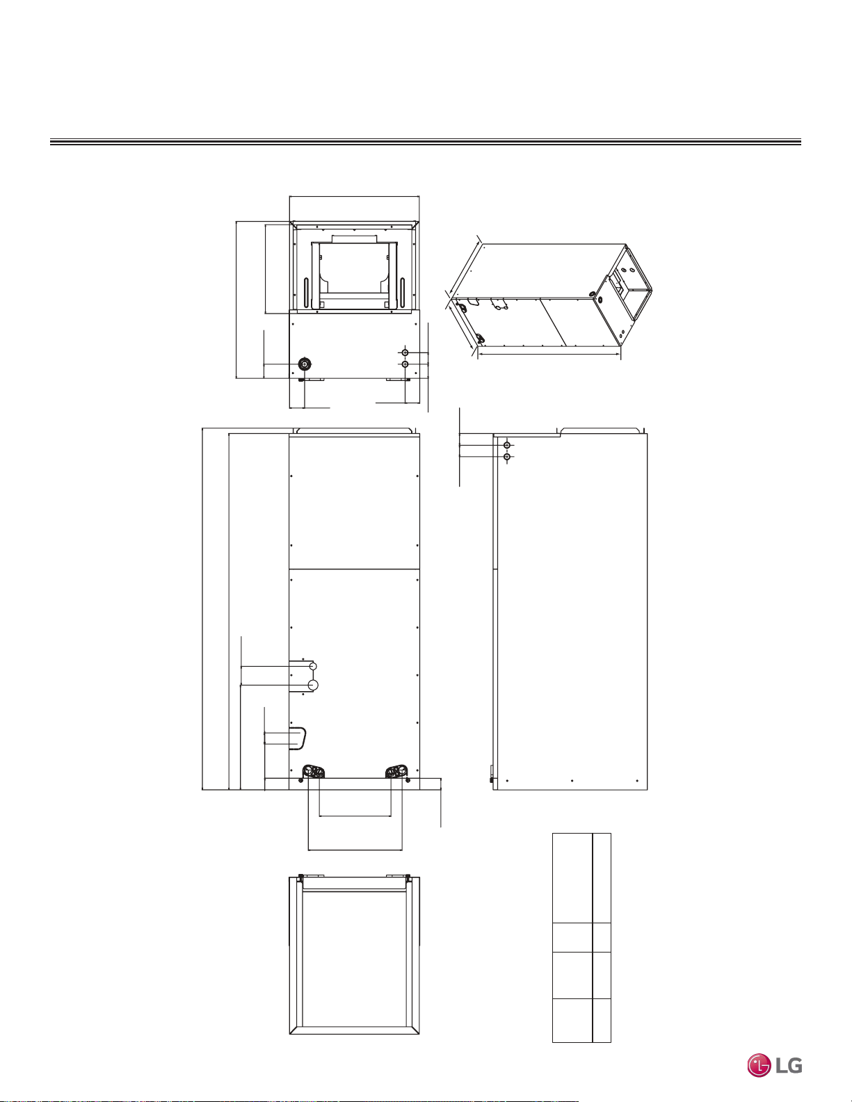
Dimensions
TWO-WAY VAHU INDOOR UNITS
Figure 216: LMVN240HV and LMVN360HV Dimensions.
WModel
LMVN240HV
LMVN360HV
18
48-21/32 21-1/4
H
Unit: Inch
H
W
D
48-21/32
49-5/16
2-9/16
1-15/16
21-1/4
12-1/8
1-1/2
9-15/16
2-1/16
18
17
2-1/8
13
4-11/16
1-9/16
1-9/16
1-9/16 1-15/16
1-5/8
14-5/16
D
Due to our policy of continuous product innovation, some specications may change without notication.
©LG Electronics U.S.A., Inc., Englewood Cliffs, NJ. All rights reserved. “LG” is a registered trademark of LG Corp.
162 | VERTICAL-HORIZONTAL
Multi F and Multi F MAX Indoor Unit Engineering Manual
MULTI
F
MAX
MULTI
F

Cooling Capacity Table
TWO-WAY VAHU INDOOR UNITS
Table 80: Multi F Vertical-Horizontal Air Handling Indoor Units Cooling Capacity Table.
TC = Total Capacity (kBtu/h).
SHC: Sensible Heat Capacity (kBtu/h).
Nominal capacity as rated 0 ft. above sea level and a 0 ft. level difference between outdoor and indoor units. Corresponding refrigerant piping length is accordance with standard length of each outdoor unit.
Nominal cooling capacity rating obtained with air entering the indoor unit at 80ºF dry bulb (DB) and 67ºF wet bulb (WB), and outdoor ambient conditions of 95ºF dry bulb (DB) and 75ºF wet bulb (WB).
The shaded table columns and rows indicate reference data. When operating at this temperature, these values can be different if the system is not running consistently.
Model No. /
Nominal Capacity
of Indoor Unit
(Btu/h)
Outdoor Air
Temp.
(°F DB)
Indoor Air Temp. °F DB / °F WB
68 / 57 73 / 61 77 / 64 80 / 67 86 / 72 90 / 75
TC SHC TC SHC TC SHC TC SHC TC SHC TC SHC
LMVN240HV
24,000
14 23.53 17.89 24.99 18.90 26.45 18.30 27.50 18.69 29.37 18.84 30.83 19.20
20 23.51 18.03 24.97 19.05 26.43 18.44 27.48 18.83 29.35 18.99 30.81 19.35
25 23.49 18.17 24.95 19.20 26.41 18.59 27.46 18.98 29.33 19.14 30.79 19.50
30 23.47 18.31 24.93 19.34 26.39 18.73 27.44 19.12 29.30 19.28 30.76 19.65
35 23.46 18.45 24.91 19.49 26.37 18.87 27.42 19.27 29.28 19.43 30.74 19.80
40 23.44 18.59 24.89 19.64 26.35 19.01 27.40 19.41 29.26 19.58 30.72 19.95
45 23.42 18.73 24.87 19.78 26.33 19.15 27.38 19.56 29.24 19.72 30.69 20.10
50 23.40 18.87 24.85 19.93 26.31 19.30 27.36 19.70 29.21 19.87 30.67 20.24
55 23.38 19.00 24.84 20.07 26.29 19.44 27.34 19.85 29.19 20.01 30.64 20.39
60 23.37 19.14 24.82 20.22 26.27 19.58 27.32 19.99 29.17 20.16 30.62 20.54
65 23.35 19.28 24.80 20.37 26.25 19.72 27.29 20.13 29.15 20.30 30.60 20.69
70 23.33 19.42 24.78 20.51 26.23 19.86 27.27 20.28 29.13 20.45 30.57 20.84
75 22.77 19.10 24.21 20.20 25.66 19.58 26.70 20.01 28.55 20.20 29.99 20.60
80 22.21 18.77 23.65 19.88 25.09 19.30 26.13 19.73 27.97 19.95 29.42 20.36
85 21.65 18.43 23.09 19.55 24.53 18.99 25.57 19.44 27.40 19.68 28.84 20.10
90 21.09 18.08 22.53 19.21 23.96 18.69 25.00 19.14 26.83 19.40 28.27 19.84
95 20.49 17.89 21.92 19.03 23.35 18.55 24.00 18.72 26.20 19.30 27.63 19.75
100 19.99 17.41 21.42 18.55 22.85 18.10 23.69 18.43 25.70 18.88 27.13 19.35
105 19.49 16.93 20.92 18.07 22.35 17.66 23.38 18.14 25.20 18.47 26.63 18.94
110 18.99 16.35 20.42 17.49 21.85 17.12 22.88 17.60 24.70 17.94 26.13 18.42
115 18.49 15.86 19.92 17.00 21.35 16.66 22.38 17.15 24.20 17.51 25.63 18.00
118 18.19 15.75 19.62 16.89 21.05 16.58 22.08 17.07 23.90 17.46 25.33 17.96
122 18.10 15.71 19.52 16.86 20.95 16.55 21.98 17.05 23.81 17.44 25.23 17.94
LMVN360HV
36,000
14 35.29 26.84 37.48 28.35 39.67 27.45 41.26 28.03 44.06 28.26 46.25 28.80
20 35.26 27.05 37.45 28.57 39.64 27.66 41.23 28.25 44.02 28.49 46.21 29.02
25 35.24 27.26 37.43 28.79 39.61 27.88 41.19 28.47 43.99 28.71 46.18 29.25
30 35.21 27.47 37.40 29.01 39.58 28.09 41.16 28.68 43.96 28.93 46.14 29.47
35 35.18 27.67 37.37 29.23 39.55 28.31 41.13 28.90 43.92 29.15 46.11 29.70
40 35.16 27.88 37.34 29.45 39.52 28.52 41.10 29.12 43.89 29.37 46.07 29.92
45 35.13 28.09 37.31 29.67 39.49 28.73 41.07 29.34 43.86 29.58 46.04 30.14
50 35.10 28.30 37.28 29.89 39.46 28.94 41.04 29.55 43.82 29.80 46.00 30.37
55 35.08 28.51 37.25 30.11 39.43 29.16 41.01 29.77 43.79 30.02 45.97 30.59
60 35.05 28.71 37.23 30.33 39.40 29.37 40.97 29.99 43.76 30.24 45.93 30.81
65 35.02 28.92 37.20 30.55 39.37 29.58 40.94 30.20 43.72 30.46 45.90 31.03
70 34.99 29.13 37.17 30.77 39.34 29.79 40.91 30.42 43.69 30.67 45.86 31.26
75 34.15 28.65 36.32 30.30 38.49 29.37 40.05 30.01 42.82 30.30 44.99 30.90
80 33.31 28.16 35.47 29.82 37.64 28.94 39.20 29.60 41.96 29.92 44.12 30.54
85 32.48 27.64 34.63 29.32 36.79 28.49 38.35 29.16 41.10 29.52 43.26 30.15
90 31.64 27.12 33.79 28.81 35.94 28.03 37.50 28.71 40.25 29.10 42.40 29.76
95 30.74 26.84 32.88 28.55 35.02 27.82 36.00 28.08 39.30 28.95 41.44 29.63
100 29.99 26.12 32.13 27.83 34.27 27.15 35.53 27.65 38.55 28.32 40.69 29.02
105 29.24 25.40 31.38 27.11 33.52 26.49 35.07 27.21 37.80 27.70 39.94 28.41
110 28.49 24.53 30.63 26.23 32.77 25.67 34.32 26.40 37.05 26.92 39.20 27.64
115 27.74 23.80 29.88 25.49 32.02 24.99 33.57 25.72 36.31 26.27 38.45 27.01
118 27.29 23.62 29.43 25.34 31.57 24.87 33.12 25.61 35.86 26.18 38.00 26.93
122 27.14 23.56 29.28 25.29 31.43 24.82 32.97 25.57 35.71 26.15 37.85 26.91
VERTICAL-HORIZONTAL | 163
Vertical-Horizontal Air Handling
Due to our policy of continuous product innovation, some specications may change without notication.
©LG Electronics U.S.A., Inc., Englewood Cliffs, NJ. All rights reserved. “LG” is a registered trademark of LG Corp.
MULTI
F
MAX
MULTI
F

Table 81: Multi F Vertical-Horizontal Air Handling Indoor Units Heating Capacity Table.
Model No. /
Nominal Capacity
of Indoor Unit
(Btu/h)
Outdoor Air Temp. Indoor Air Temp. °F DB
°F DB °F WB
61 64 68 70 72 75
TC TC TC TC TC TC
LMVN240HV
24,000
0 -0.4 13.89 13.70 13.57 13.50 13.30 12.72
5 4.5 15.65 15.46 15.33 15.26 15.07 14.48
10 9 17.41 17.22 17.09 17.02 16.83 16.24
17 15 19.76 19.57 19.43 19.37 19.17 18.55
20 19 20.64 20.45 20.32 20.25 20.05 19.37
25 23 22.11 21.91 21.78 21.72 21.52 20.74
30 28 23.38 23.18 23.05 22.99 22.79 22.11
35 32 24.65 24.46 24.33 24.26 24.07 23.48
40 36 25.79 25.60 25.47 25.40 25.21 24.62
45 41 26.93 26.74 26.61 26.54 26.35 25.76
47 43 27.39 27.20 27.07 27.00 26.80 26.22
50 46 27.83 27.64 27.51 27.44 27.24 26.58
55 51 28.57 28.37 28.24 28.17 27.98 27.20
60 56 28.57 28.37 28.24 28.17 27.98 27.32
63 59 28.57 28.37 28.24 28.17 27.98 27.39
68 64 28.57 28.37 28.24 28.17 27.98 27.51
LMVN360HV
36,000
0 -0.4 20.58 20.29 20.10 20.00 19.71 18.84
5 4.5 23.19 22.90 22.71 22.61 22.32 21.45
10 9 25.80 25.51 25.31 25.22 24.93 24.06
17 15 29.28 28.99 28.79 28.70 28.41 27.48
20 19 30.58 30.29 30.10 30.00 29.71 28.70
25 23 32.75 32.46 32.27 32.17 31.88 30.72
30 28 34.64 34.35 34.15 34.06 33.77 32.75
35 32 36.52 36.23 36.04 35.94 35.65 34.78
40 36 38.21 37.92 37.73 37.63 37.34 36.47
45 41 39.90 39.61 39.42 39.32 39.03 38.16
47 43 40.58 40.29 40.10 40.00 39.71 38.84
50 46 41.23 40.94 40.75 40.65 40.36 39.38
55 51 42.32 42.03 41.84 41.74 41.45 40.29
60 56 42.32 42.03 41.84 41.74 41.45 40.47
63 59 42.32 42.03 41.84 41.74 41.45 40.58
68 64 42.32 42.03 41.84 41.74 41.45 40.76
TWO-WAY VAHU INDOOR UNITS
Heating Capacity Table
TC = Total Capacity (kBtu/h).
Nominal capacity as rated 0 ft. above sea level and a 0 ft. level difference between outdoor and indoor units. Corresponding refrigerant piping length is accordance with standard length of each outdoor unit.
Nominal heating capacity rating obtained with air entering the indoor unit at 70ºF dry bulb (DB) and 60ºF wet bulb (WB), and outdoor ambient conditions of 47ºF dry bulb (DB) and 43ºF wet bulb (WB).
Due to our policy of continuous product innovation, some specications may change without notication.
©LG Electronics U.S.A., Inc., Englewood Cliffs, NJ. All rights reserved. “LG” is a registered trademark of LG Corp.
164 | VERTICAL-HORIZONTAL
Multi F and Multi F MAX Indoor Unit Engineering Manual
MULTI
F
MAX
MULTI
F
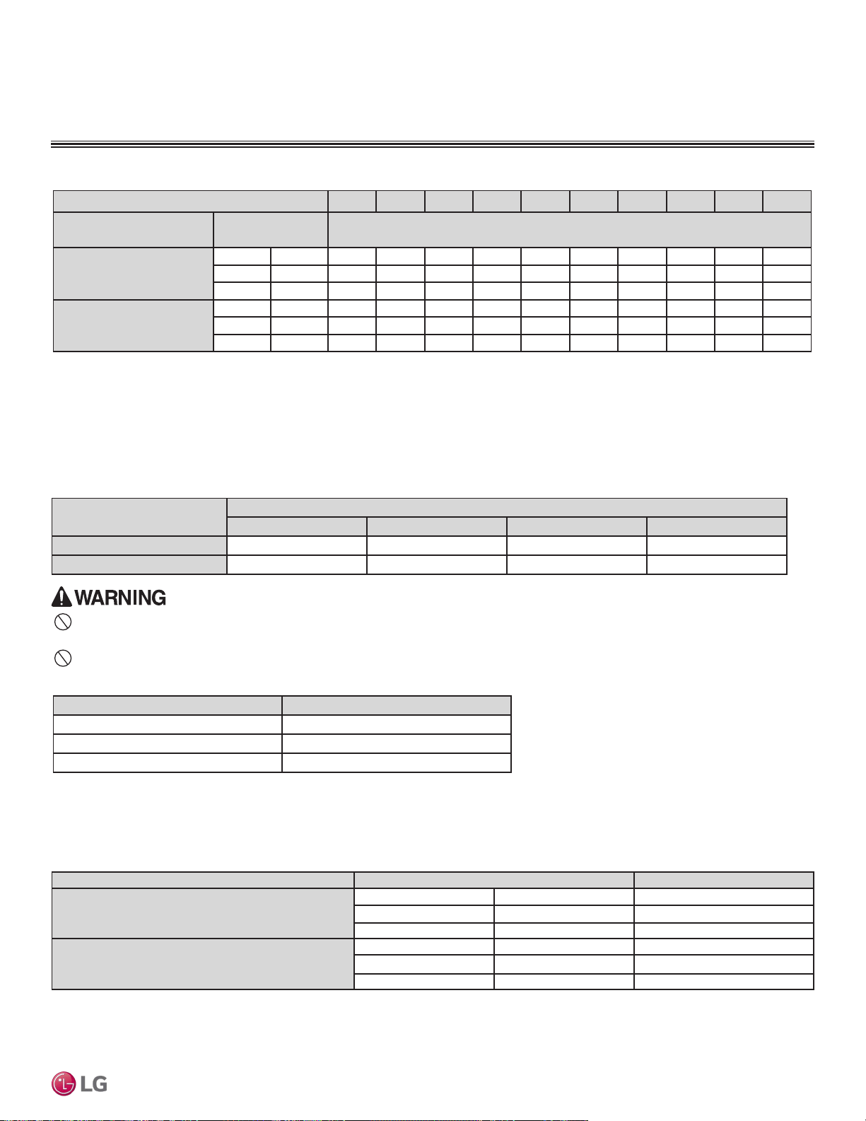
External Static Pressure
TWO-WAY VAHU INDOOR UNITS
Static Pressure (in. wg) 0.1 0.2 0.3 0.4 0.5 0.6 0.7 0.8 0.9 1.0
Model No. / Nominal Capacity
of Indoor Unit (Btu/h)
Airflow Rate / CFM Setting Value at (in. wg)
1
LMVN240HV
24,000
High 710 56 67 74 78 87 94 98 98
2
98
2
98
2
Mid 640 53 65 70 75 85 91 96 96
2
96
2
96
2
Low 480 53 55 64 70 79 84 92 92
2
92
2
92
2
LMVN360HV
36,000
High 990 80 85 90 95 100 103 103
2
103
2
103
2
103
2
Mid 880 65 72 80 85 92 98 103 103
2
103
2
103
2
Low 800 65 69 77 82 90 96 101 101
2
101
2
101
2
1
Unless otherwise noted, vertical-horizontal air handing units are UL listed up to 0.5 in. wg total static pressure, including coil, case, duct work pressure drop, air filter, and largest kW size heater. Internal static
pressure includes coil and case only.
2
Airflow rate (CFM) decreases by 3% per 0.1 in. wg.
3
Maximum airflow rate is 400 CFM per ton. (For the 24,000 Btu/h unit, the maximum airflow rate is 2 x 400 = 800 CFM). If airflow is set at the maximum rate, the external static pressure value must be increased
from high speed setting value to: From 24kBtu/h of capacity: 4; From 36kBtu/h of capacity: 5
4
High static pressure is 0.5 in. wg (factory setting); low static pressure is 0.3 in. wg.
Note:
If external static pressure is not set correctly, the air conditioning system will not operate properly or will malfunction.
Table 82: Multi F Vertical-Horizontal Air Handling Unit External Static Pressure Setting Values Table.
Model No. / Nominal Capacity of
Indoor Unit (Btu/h)
Heater Capacity (kW)
5 10 15 20
LMVN240HV (24,000)
480 CFM 480 CFM Not Available Not Available
LMVN360HV (36,000)
780 CFM 780 CFM Not Available Not Available
Table 83: Multi F Vertical-Horizontal Air Handling Unit Minimum Airow by Heater Capacity.
Do not operate the air conditioning system using less than the minimum airow. There is risk of re and severe injury or death.
Heater Capacity (kW) Static Pressure Drop (in. wg)
0
0
5
-0.01
10
-0.02
Table 84: Electric Heater Static Pressure Drop.
Note:
• The external static pressure value must be reset if an electric heater is installed. For each 0.01 in. wg. increase in static pressure, the
external static pressure must increase by 1.
• If the external static pressure is not set properly, the provided safety device will turn off the heater (according to airflow).
Table 85: Field-Supplied Air Filter Static Pressure Drop Factors.
Model No. / Nominal Capacity of Indoor Unit (Btu/h) Airow Rate / CFM Static Pressure Drop (in. wg)
LMVN240HV (24,000)
High 710 -0.04
Mid 640 -0.03
Low 480 -0.03
LMVN360HV (36,000)
High 990 -0.07
Mid 880 -0.05
Low 800 -0.05
Note:
• The external static pressure value must be reset if an air filter is installed. For each 0.01 in. wg. increase in static pressure, the
external static pressure must increase by 1.
• Factory tested with MERV 4 filter media. Fan speed set value when the unit is used with field-supplied filter media.
Note:
Do not operate the air conditioning system using less than the minimum airow. There is risk of product damage.
VERTICAL-HORIZONTAL | 165
Vertical-Horizontal Air Handling
Due to our policy of continuous product innovation, some specications may change without notication.
©LG Electronics U.S.A., Inc., Englewood Cliffs, NJ. All rights reserved. “LG” is a registered trademark of LG Corp.
MULTI
F
MAX
MULTI
F
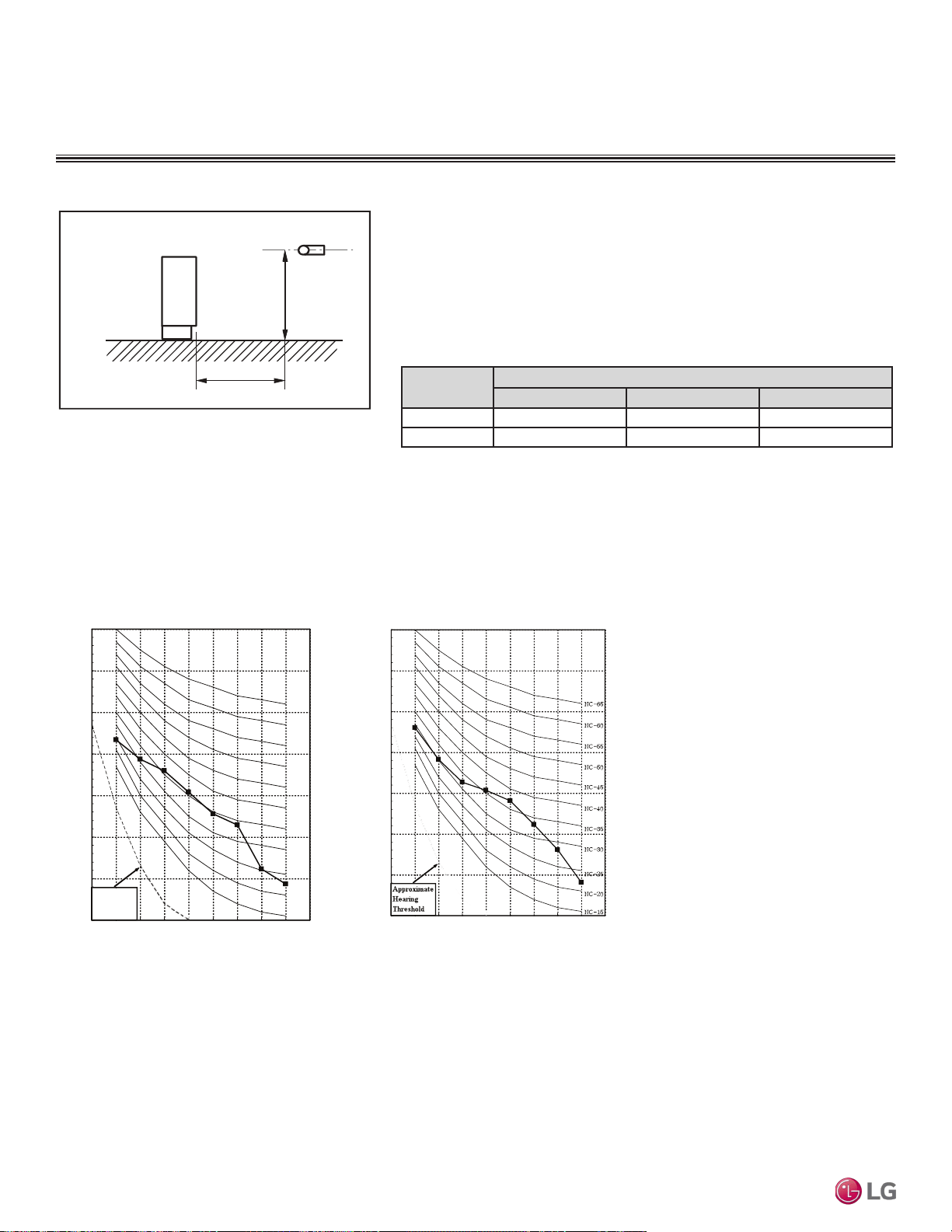
TWO-WAY VAHU INDOOR UNITS
Acoustic Data
• Measurement taken 3.3′ away from the unit.
• Measurements taken with no attenuation and units operating at full load normal
operating condition.
• Sound level will vary depending on a range of factors such as construction
(acoustic absorption coefficient) of particular area in which the equipment is
installed.
• Sound power levels are measured in dB(A).
• Tested in anechoic chamber per ISO Standard 3745.
Figure 217: Sound Pressure Level Measurement Location.
Table 86: Sound Pressure Levels (dB[A]).
Figure 218: Sound Pressure Level Diagrams.
Model No.
Sound Pressure Levels (dB[A]) (Cooling and Heating)
High Fan Speed Medium Fan Speed Low Fan Speed
LMVN240HV 43 42 41
LMVN360HV 45 44 43
3.3 ft.
3.3 ft.
With Case
Microphone
Octave Band Center Frequency (Hz)
Octave Band Sound Pressure Level (dB = 20μPa)
10
20
30
40
50
60
70
80
63 125250 5001000200040008000
Approximate
Hearing
Threshold
NC-15
NC-20
NC-25
NC-30
NC-35
NC-40
NC-45
NC-50
NC-55
NC-60
NC-65
Octave Band Sound Pressure Level (dB = 20μPa)
10
20
30
40
50
60
70
80
Octave Band Center Frequency (Hz)
63 125250 500 1000 2000 4000 8000
LMVN240HVLMVN360HV
Due to our policy of continuous product innovation, some specications may change without notication.
©LG Electronics U.S.A., Inc., Englewood Cliffs, NJ. All rights reserved. “LG” is a registered trademark of LG Corp.
166 | VERTICAL-HORIZONTAL
Multi F and Multi F MAX Indoor Unit Engineering Manual
MULTI
F
MAX
MULTI
F
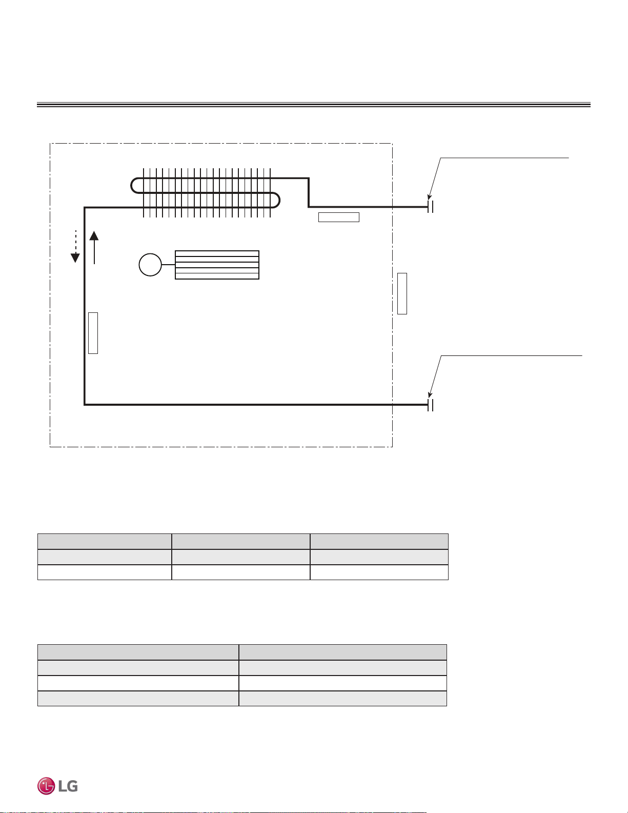
Refrigerant Flow Diagram
Figure 219: Multi F Vertical-Horizontal Air Handling Indoor Unit Refrigerant Flow Diagram.
TWO-WAY VAHU INDOOR UNITS
Table 87: Multi F Vertical-Horizontal Air Handling Indoor Unit Refrigerant Pipe Connection Port Diameters.
Model No. Vapor (inch) Liquid (inch)
LMVN240HV 1/2 1/4
LMVN360HV 5/8 3/8
Table 88: Multi F Vertical-Horizontal Air-Handling Indoor Unit Thermistor Details.
Description (Based on Cooling Mode) PCB Connector
Indoor Air Temperature Thermistor CN-ROOM
Evaporator Inlet Temperature Thermistor CN-PIPE/IN
Evaporator Outlet Temperature Thermistor CN-PIPE/OUT
Gas pipe connection port
(flare connection)
Liquid pipe connection port
(flare connection)
Cooling
Heating
Thermistor for
Evaporator Inlet Temperature
Thermistor for
Indoor Air Temperature
Thermistor for Evaporator
Outlet Temperature
Heat Exchanger
Cross Flow Fan
M
VERTICAL-HORIZONTAL | 167
Vertical-Horizontal Air Handling
Due to our policy of continuous product innovation, some specications may change without notication.
©LG Electronics U.S.A., Inc., Englewood Cliffs, NJ. All rights reserved. “LG” is a registered trademark of LG Corp.
MULTI
F
MAX
MULTI
F
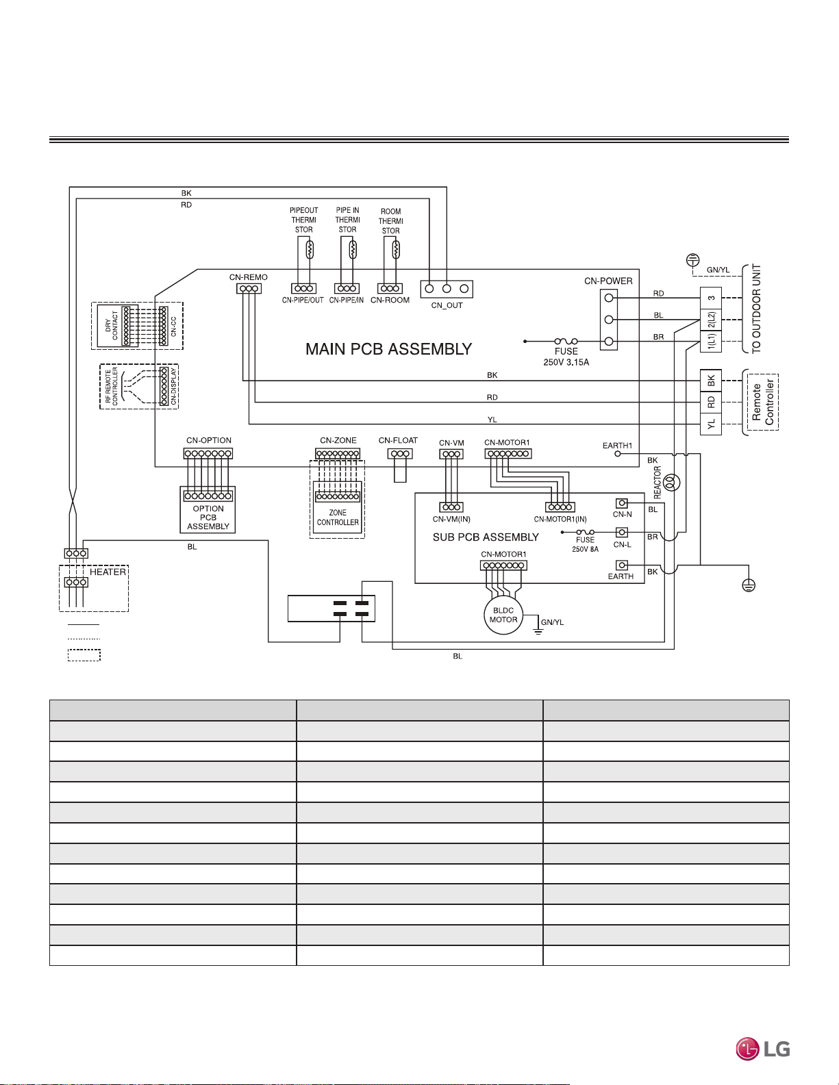
Wiring Diagram
TWO-WAY VAHU INDOOR UNITS
Figure 220: Multi F Vertical-Horizontal Air-Handling Indoor Unit Wiring Diagram.
: Factory Wiring
: Field Wiring
: OPTION
Connection Name Location Function
CN-POWER AC power supply AC Power line input for indoor controller
CN-MOTOR1 Fan motor output Motor output of BLDC
CN-MOTOR2 Fan motor output Motor output of BLDC
CN-FLOAT Float switch input Float switch sensing (water level sensor)
CN-PIPE/IN Suction pipe sensor Pipe in thermistor
CN-PIPE/OUT Discharge pipe sensor Pipe out thermistor
CN-ROOM Room sensor Room thermistor
CN-REMO Remote controller Remote control line
CN-OPTION Option PCB Communication between main and option
CN-ZONE Zone controller Zone control line
CN-DISPLAY RF Remote controller RF Remote control line
CN-CC Dry contact Dry contact line
Table 89: Wiring Diagram Connections.
Due to our policy of continuous product innovation, some specications may change without notication.
©LG Electronics U.S.A., Inc., Englewood Cliffs, NJ. All rights reserved. “LG” is a registered trademark of LG Corp.
168 | VERTICAL-HORIZONTAL
Multi F and Multi F MAX Indoor Unit Engineering Manual
MULTI
F
MAX
MULTI
F
Table 90: DIP Switch Settings.
Dip Switch Settings OFF ON Description
SW3 GROUP Master Slave Group control setting using wired remote controller.
SW4
DRY
CONTACT
Variable Auto
Dry contact mode setting.
1. Variable: Auto/manual mode can be chosen using the wide wired
remote controller or wireless remote controller (factory setting is
the manual mode).
2. Auto: For dry contact, it is always auto mode.
SW5 EXTRA1 Off On
• ON: Fan operates continuously.
• OFF: Default (Fan does not operate continuously).
SW6 HEATER Off On
• ON: Automatic heater operation.
• OFF: Default (manual heater operation).
1. Indoor unit without electric heater.
• DIP switch 1, 2, 6, 8 must be set to OFF.
2. Indoor unit with electric heater, DIP switches 5 and 6 must be set to ON.
• SW 5 ON: Fan operates continuously. (Can have uninterrupted heating during defrost or oil return modes using continuous heater and
fan operation.)
• SW5 OFF: Fan discontinuous operation. (There would be reduction in heating capacity while defrosting or oil return operation.)
• SW6 ON: Automatic heater operation. (Heater operates automatically using the heater algorithm.)
• SW6 OFF: Manual heater operation. (On / off operation is set manually. Heater operation follows the heater algorithm.)
Wiring Diagram
TWO-WAY VAHU INDOOR UNITS
VERTICAL-HORIZONTAL | 169
Vertical-Horizontal Air Handling
Due to our policy of continuous product innovation, some specications may change without notication.
©LG Electronics U.S.A., Inc., Englewood Cliffs, NJ. All rights reserved. “LG” is a registered trademark of LG Corp.
MULTI
F
MAX
MULTI
F
TWO-WAY VAHU INDOOR UNITS
Factory Supplied Parts and Materials
Factory Supplied Materials
• Owner’s Manual
• Installation Manual
Required Tools
• Level
• Screwdriver
• Electric drill
• Hole core drill
• Flaring tool set
• Torque wrenches
• Hexagonal wrench
• Gas-leak detector
• Thermometer
Selecting the Best Location
Do’s
• Place the unit where air circulation through the ducts will not be
blocked.
• Place the unit where drainage can be obtained easily.
• Place the unit where noise prevention is taken into consideration.
• Ensure there is sufficient strength to bear the load of the indoor
unit.
• Ensure there is sufficient maintenance space.
• Locate the indoor unit in a location that is level, and where it can
be easily connected to the outdoor unit / branch distribution unit.
Installing in an Area Exposed to Unconditioned Air
In some installation applications, areas (floors, walls) in some rooms will be exposed to unconditioned air (room will be above or next to an
unheated garage or storeroom). To countermeasure:
• Verify that carpet is or will be installed (carpet will increase the temperature by three degrees).
• Add insulation between the floor joists.
• Install radiant heat or another type of heating system to the floor.
Installing in an Area with High Humidity Levels
If the environment is prone to humidity levels of 80% or more (near the ocean, lakes, etc.) or where steam could collect in the plenum:
• Install additional insulation to the indoor unit (glass wool insulation >13/32 inches thick).
• Install additional insulation to the refrigerant piping (insulation >13/16 inches thick).
• Seal all gaps between the indoor unit and the ceiling tiles (make the area air tight) so that humidity does not transfer from the plenum to the
conditioned space. Also, add a ceiling grille for ventilation.
WARNING
Installation work must be performed by trained personnel and in accordance with national wiring standards and all local or other applicable codes.
Improper installation can result in re, electric shock, physical injury, or death.
Note:
Read all instructions before installing this product. Become familiar with the unit’s components and connections, and the order of installation. Incorrect
installation can degrade or prevent proper operation.
Don’ts
• Do not install the unit near a heat or steam source, or where
considerable amounts of oil, iron powder, or flour are used.
• Do not install the unit where sulfuric acid and flammable or cor-
rosive gases are generated, vented into, or stored.
• Do not install the unit near high-frequency generators.
• Do not install the unit near a doorway.
The unit will be damaged, will malfunction, and/or will not op-
erate as designed if installed in any of the conditions listed.
• Indoor units (IDUs) must not be placed in an environment where the IDUs will be exposed to harmful volatile organic compounds
(VOCs) or in environments where there is improper air make up or supply or inadequate ventilation. If there are concerns about VOCs in
the environment where the IDUs are installed, proper air make up or supply and/or adequate ventilation must be provided. Additionally, in
buildings where IDUs will be exposed to VOCs, consider a third party factory-applied epoxy coating to the fan coils for each IDU where the
entire coil is dipped, not sprayed.
• If the unit is installed near a body of water, the installation parts are at risk of corroding. Appropriate anti-corrosion methods must be taken
for the unit and all installation parts.
Due to our policy of continuous product innovation, some specications may change without notication.
©LG Electronics U.S.A., Inc., Englewood Cliffs, NJ. All rights reserved. “LG” is a registered trademark of LG Corp.
170 | VERTICAL-HORIZONTAL
Multi F and Multi F MAX Indoor Unit Engineering Manual
MULTI
F
MAX
MULTI
F
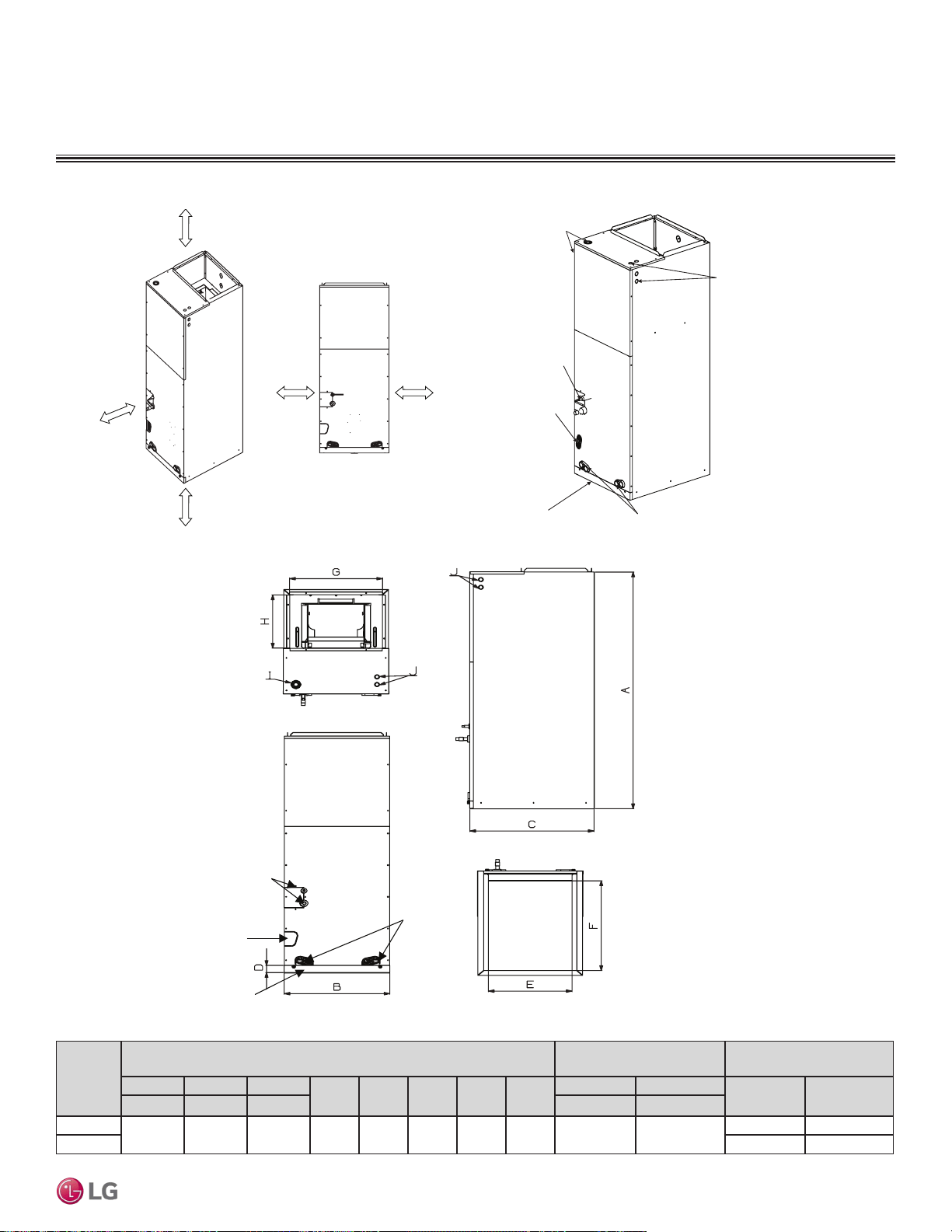
TWO-WAY VAHU INDOOR UNITS
Installation and Best Layout Practices
Capacity
(Btu/h)
Dimensions (inches)
Access Hole for Wiring /
Cable (inches)
Refrigerant Connection
Sizes (inches)
A B C
D E F G H
I J
Liquid Vapor
Height Width Depth Power Comm.
24,000
48-21/32 18 21-1/4 1-9/16 17-1/2 20 17 12-1/8 1-11/16 7/8
1/4 1/2
36,000 3/8 5/8
Top
Front
Bottom
Right Side
Refrigerant Piping
Connections
Drain Connections
for Horizontal Install
Drain
Connections
for Vertical Install
Air Filter Cover
>23-5/8
Clearance from
Access Panels
for Service
0 (zero)
inches
>13-25/32 inches
>13-25/32 inches
0 (zero)
inches
Figure 221:Clearance Requirements.
Figure 222:General and Duct Connection Dimensions.
Table 91:General and Duct Connection Dimensions.
Refrigerant Piping
Connections
Drain Connections
for Horizontal Install
Filter Access
Drain Connections
for Vertical Install
Access Holes
for Conduit
Access Holes
for Conduit
Figure 223:Location of Access Holes and Piping Connections.
VERTICAL-HORIZONTAL | 171
Vertical-Horizontal Air Handling
Due to our policy of continuous product innovation, some specications may change without notication.
©LG Electronics U.S.A., Inc., Englewood Cliffs, NJ. All rights reserved. “LG” is a registered trademark of LG Corp.
MULTI
F
MAX
MULTI
F
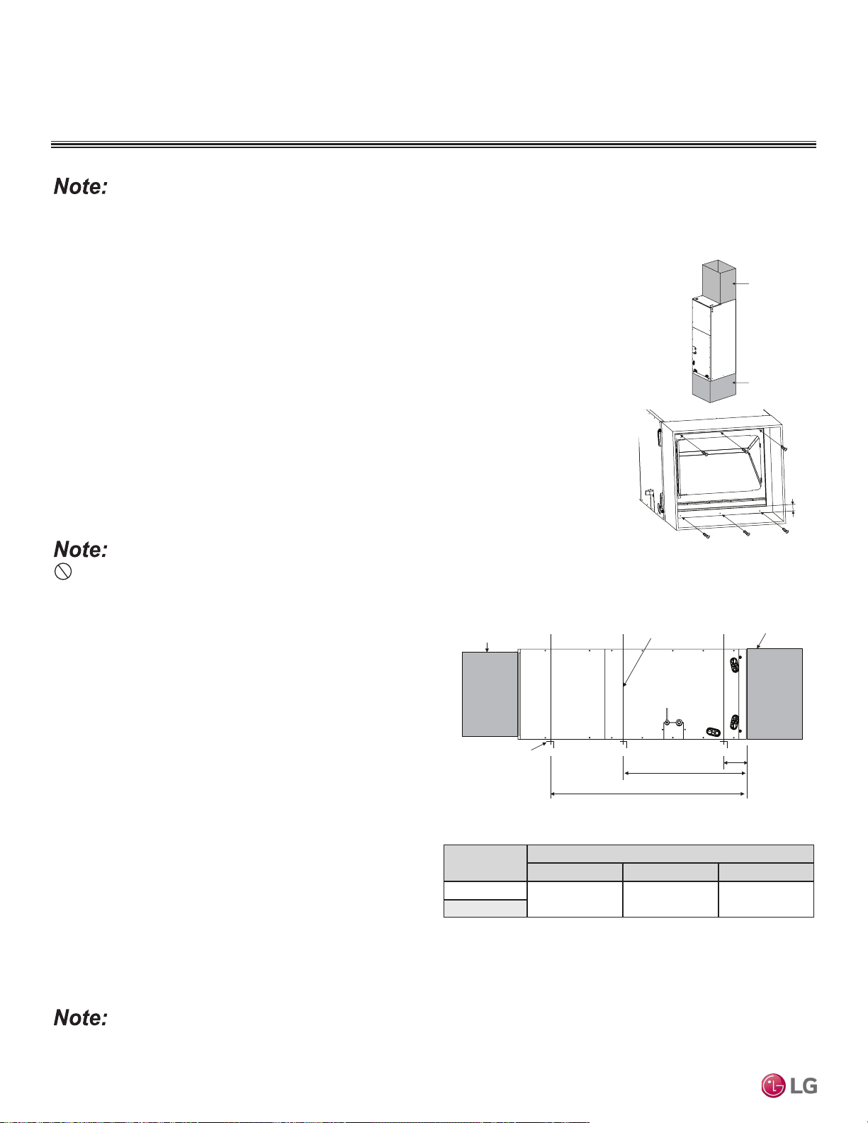
Horizontal Installation
• Units must be installed so that the access panels face to the side,
not facing up or down.
• Installation must be in accordance with all relevant building codes,
which will necessitate the installation of an external condensate
pan (position the unit in or above the external condensate pan).
• If the units are going to be suspended, use angled steel support
brackets with threaded rods to provide support from the bottom.
The brackets / threaded rods must be comparatively bigger / longer
than the unit, and each must be centered on the part of the frame
it supports.
• If the unit will not be suspended, still use angled steel support
brackets, but also add vibration isolators (field supplied) to avoid
sound transmission. If necessary, provide the installing contractor
with an illustration of where the vibration isolator must be added
and how it must be positioned.
• Unit must be positioned properly for plenum / duct installation.
• Plenum must be strong and secure enough to support the installa-
tion of adapter collars to accommodate duct work.
To ensure proper drainage for horizontal installations, unit must be installed within ±1/8 inches level of the unit’s length and width.
Vertical-Horizontal Air Handling Units can be installed in a choice of vertical (upow) or horizontal (left side) congurations.
Vertical (Upflow) Installation
• Unit must be positioned properly for plenum / duct installation.
• To maintain proper air flow, minimum height clearance is 14 inches.
• Plenum must be strong and secure enough to support the installation of adapter collars to accommo-
date duct work.
• Air handler platform must be sturdy enough to support the frame, plus any accessories (e.g., filter box).
• To prevent air leaks, seal all duct work according to local codes, but make sure that filter access is still
unobstructed.
• Vibration isolators (field supplied) must be installed between the unit frame and the platform. If neces-
sary, provide the installing contractor with an illustration of where the vibration isolator must be added
and how it must be positioned.
Do not install the screws on the front and back of the unit, doing so will block lter installation.
Use > 6 Screws (M4*25L)
Field Supplied
Return Air Duct /
Plenum
>1 inch
Field Supplied
Supply Air Duct
Figure 224:Vertical Installation /
Attaching the Bottom Duct.
B
A
C
>1-1/2 inch x 1-1/2 inch Angle
Recommended length >26 inches
with a 2-inch clearance on both
sides of the unit
>3/8 inch Threaded Rod
Field-Supplied
Supply Air Duct
Field Supplied
Return Air Duct / Plenum
Suspension Bolt Locations
Capacity
(Btu/h)
Dimensions (inches)
A B C
24,000
4 23 41-11/32
36,000
Figure 225:Horizontal Installation.
Table 92:Bracket / Bolt Position Dimensions.
TWO-WAY VAHU INDOOR UNITS
Installation and Best Layout Practices
Due to our policy of continuous product innovation, some specications may change without notication.
©LG Electronics U.S.A., Inc., Englewood Cliffs, NJ. All rights reserved. “LG” is a registered trademark of LG Corp.
172 | VERTICAL-HORIZONTAL
Multi F and Multi F MAX Indoor Unit Engineering Manual
MULTI
F
MAX
MULTI
F
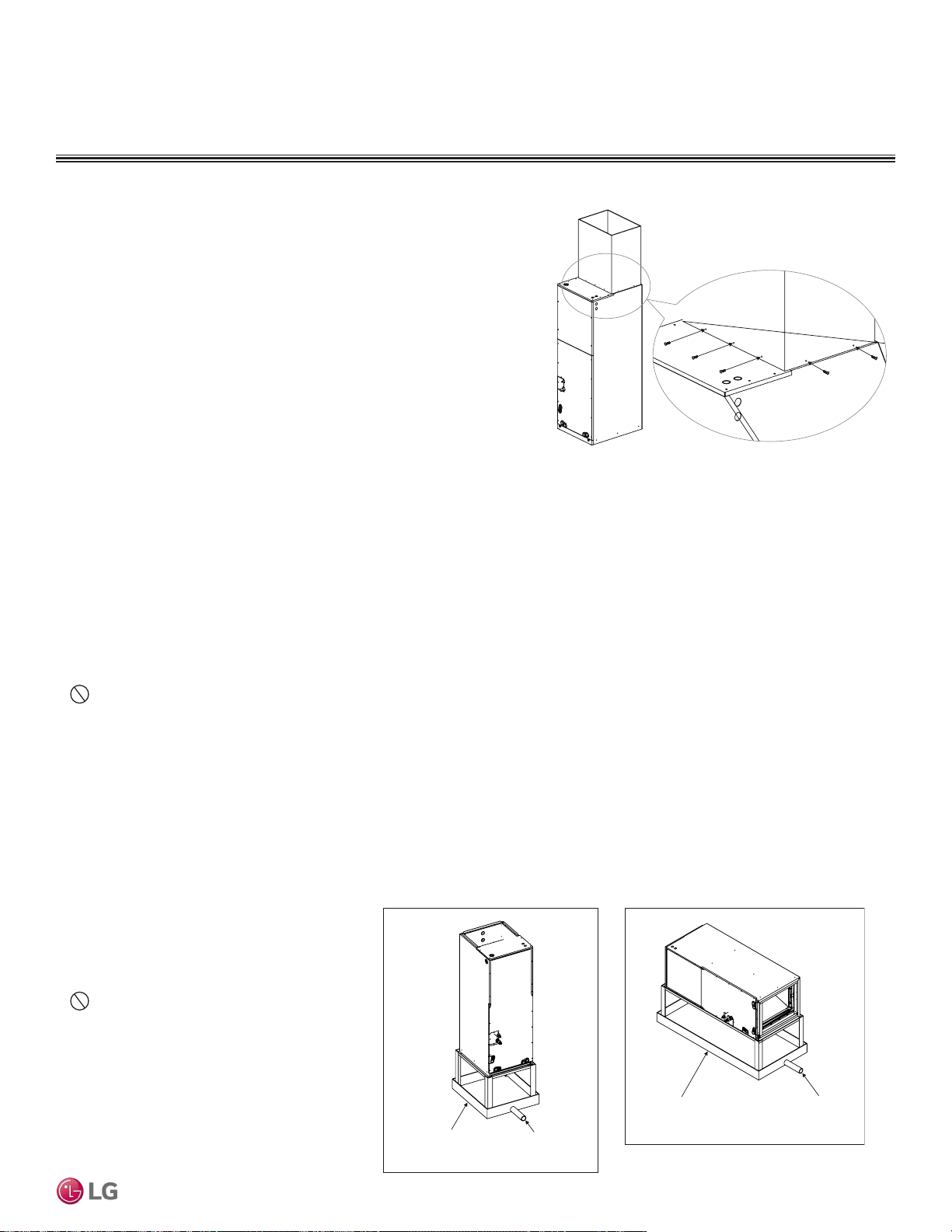
Installing the Ducts
• Use more than ten (10) screws to securely attach the supply ducts to the
unit. To prevent air leaks, seal around the duct opening before the duct is
secure.
• To prevent vibration transmission, install flexible connectors between ducts
and the unit. The flexible connectors must be made of a heat-resistant
material at the discharge connection if an electric heater is installed.
• Duct work must be insulated and covered with vapor barrier when routed
through unconditioned spaces. Include enough insulation to prevent
condensate from forming on the ducts.
• It will be necessary to add internal acoustical insulation lining for a metal
duct system if it does not include a 90° elbow and ten (10) feet between the
main duct and the first branch.
• Fibrous glass ducts could be used as a substitute if built and installed in accordance with the most recent edition of the Sheet Metal and
Air-Conditioning Contractors’ National Associate (SMACNA) standard.
• Also, fibrous duct work and acoustical insulation lining must also follow National Fire Protection Standard 90A or B as tested by UL
Standard 181 for Class 1 air ducts.
TWO-WAY VAHU INDOOR UNITS
Installation and Best Layout Practices
>10 Screws
(M4*25L)
Figure 226:Securing the Ducts to the Unit.
Installing the Drain System
General Specifications
• To prevent property damage, optimize drain system performance by installing both a primary and secondary drain line, and properly size
the condensate traps.
• The primary and secondary drain line must be trapped to allow proper drainage of condensate water. If the secondary drain line is not used,
it must be capped.
• Do not block the filter access panel when installing the condensate drain piping. Prime the primary and secondary condensate traps
after running both to the drain pan.
• If the unit is installed above an inhabited space, add a field-supplied external condensate pan that runs underneath the entire frame (to
prevent damage from overflow). The additional external condensate line must run from the unit to the external condensate pan.
• Drain all generated condensate from the external condensate pan to an appropriate area. Install a trap in the condensate lines as near to
the indoor unit coil as possible.
• All condensate must be drained from the external condensate pan to some noticeable area.
• To prevent overflow, the outlet of each trap must be positioned below its connection to the condensate pan.
• All traps must be primed, insulated, and leak
tested if located above an inhabited space.
• Use a 3/4-inch PVC male pipe thread fitting at
the condensate pan connection. Tighten gently.
• Point the drain hose down for easier flow.
• Do not just use the pipe joint or PVC /
CPVC piping on the indoor unit drain line con-
nections. Use only Teflon tape.
• Design the drain system to plan for winter opera-
tion (condensate line will freeze up if condensate
does not properly drain away).
Field-Supplied
Drain Pan
Drain Piping
Field-Supplied
Drain Pan
Drain Piping
Figure 227:Vertical Installation Drain System. Figure 228:Horizontal Installation Drain
System.
VERTICAL-HORIZONTAL | 173
Vertical-Horizontal Air Handling
Due to our policy of continuous product innovation, some specications may change without notication.
©LG Electronics U.S.A., Inc., Englewood Cliffs, NJ. All rights reserved. “LG” is a registered trademark of LG Corp.
MULTI
F
MAX
MULTI
F
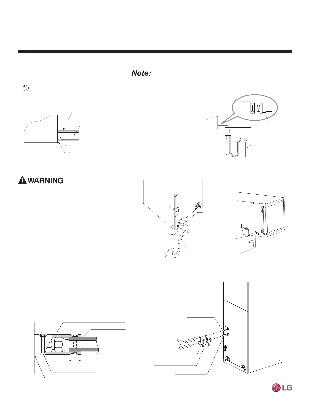
TWO-WAY VAHU INDOOR UNITS
Installation and Best Layout Practices
Drain Piping Specifications
• Drain piping must have downward gradient of at
least 1/50 to 1/100; to prevent reverse flow, slope
must not be straight up and down.
• Do not damage the drain port on the indoor unit
when connecting the field-supplied drain piping.
Drain Hole
Gaps Should Not Be Present
Unit
Drain Piping
(Field Supplied)
Drain Piping Insulation
(Field Supplied)
U-Trap
B
C
A
3/4-inch Connecto
r
Field-Installed U-Trap Specifications
Figure 229:Close up of Drain Piping Connection.
Figure 230:Installing the U-Trap.
To prevent leaks cause by a block in the intake air lter, install a U-Trap.
A ≥ 2-9/16 inches
B ≥ 2C
C ≥ 2 x SP
SP = External Pressure in. WG
Example:
External Pressure= 0.4 in WG
A ≥ 2-9/16 inches
B ≥ 1-7/12 inches
C ≥ 19/24 inches
Drain Access Hole
Air Filter Cover
Main Drain with Suitable Trap. (Field-Supplied
Trap with Sufficient Depth Can Be Used.
Standard Size P-Traps Cannot Be Used.
Supplementary Drain with a
Proper Trap (Field Supplied Kit
Can Be Used)
Figure 231:Vertical Primary and
Secondary Drain Layout.
Figure 232:Horizontal Primary and
Secondary Drain Layout.
Refrigerant Piping Insulation
Field-installed vapor and liquid refrigerant piping lines must
be properly and completely covered in insulation (up to the
indoor unit piping connections) and must comply with federal,
state, and local requirements. Any exposed piping will gener-
ate condensate or will cause burns if touched. Insulation for
this field-installed refrigerant piping must have a minimum heat
resistance of 248°F.
If the indoor unit is installed and is operated at an extended
period in a highly humid environment (dew point tempera-
ture >73°F), however, condensate will form. To prevent this
phenomenon, install adiabatic glass wool insulation with a
thickness of 7/16 to 13/16 inches thick. Also, install glass wool
insulation on all indoor units that are located in the ceiling
plenum.
Drain Piping Insulation
Drain piping insulation must be 7/32 inches thick, minimum.
Insulating the Refrigerant and
Drain Piping
Connection for Liquid Piping
Refrigerant Piping
Insulation (Field Supplied)
Connection for Vapor Piping
Insulation Zip Tie (Field Supplied)
Refrigerant Piping Insulation (Field
Supplied)
Figure 233:Close Up of Refrigerant Piping Connection Insulation.
Gaps Should Not be Present
Overlap Piping Insulation
Refrigerant Piping Insulation (Field Supplied)
Insulation Clip (Field Supplied)
Refrigerant Piping Insulation
(Field Supplied)
Figure 234:Insulating the Refrigerant Piping and Refrigerant Piping
Connections.
Ensure all piping is insulated. Exposed piping can cause
burns if touched.
Due to our policy of continuous product innovation, some specications may change without notication.
©LG Electronics U.S.A., Inc., Englewood Cliffs, NJ. All rights reserved. “LG” is a registered trademark of LG Corp.
174 | VERTICAL-HORIZONTAL
Multi F and Multi F MAX Indoor Unit Engineering Manual
MULTI
F
MAX
MULTI
F
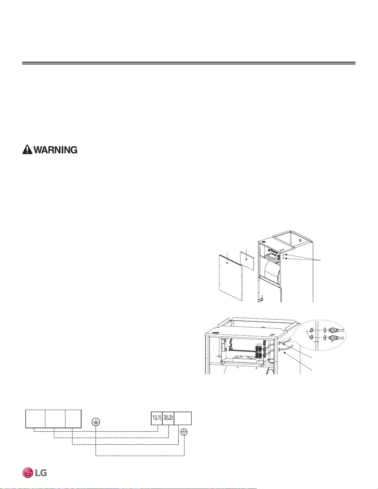
TWO-WAY VAHU INDOOR UNITS
Installation and Best Layout Practices
Power Wiring / Communications Cable Guidelines
• Follow manufacturer’s circuit diagrams in the technical manuals.
• Confirm power source specifications.
• Confirm that the electrical capacity is sufficient.
• Starting current must be maintained ±10 percent of the rated current marked on the outdoor unit name plate.
• Confirm cable thickness specifications.
• It is required that a circuit breaker is installed, especially if conditions could become wet or moist.
• Include a disconnect in the power wiring system, add an air gap contact separation of at least 1/8 inch in each active (phase) conductor.
Access Holes
for Wiring
Control
Box Cover
Top Front
Panel
Connection Cable
Communications Cable
Nut
Conduit
Mounting Plate
1/2-inch Conduit
Connecting the Power Wiring and Communications Cable
1. To access the terminal block, first unscrew the top front panel,
and then unscrew the cover from the control box.
2. Knockout the access holes for the wiring. Insert the power wiring/
communications cable from the outdoor unit or branch distribution
unit (Multi F MAX systems only) through the conduits, pass the
conduits through the designated access holes, and then insert
the conduits into the control box. To prevent electromagnetic
interference and product malfunction, leave a space between the
power wiring and communications cable outside of the indoor
unit.
3. Connect the power wiring and communications cables to the
appropriate terminals on the indoor unit control board. Verify that
the color and terminal numbers from the outdoor unit or branch
distribution unit (Multi F MAX systems only) wiring match the
color and terminal numbers on the indoor unit.
4. Fill in any gaps around the conduit access holes with sealant to
prevent foreign particles from entering the indoor unit.
Figure 235:Connecting the Power Wiring and Communications Cable.
Indoor Unit Terminal Block
1(L1 )2(L2)
GND
3
Outdoor Unit Terminal Block or
Branch Distribution Unit Terminal Block
(Multi F MAX Systems Only)
GND
GRN /
YLW
BR
BL
RD
3 or S
Figure 236:Indoor Unit to Outdoor Unit / Branch Distribution Unit (Multi F MAX
systems only) Power Wiring / Communications Cable Connections.
• Loose wiring will cause unit to malfunction, overheat, and catch fire, resulting in severe injury or death.
Note:
• Terminal screws will become loose during transport. Properly tighten the terminal connections during installation.
A voltage drop will cause the following problems:
• Magnetic switch vibration, fuse breaks, or disturbance to the normal function of an overload protection device.
• Compressor will not receive the proper starting current.
VERTICAL-HORIZONTAL | 175
Vertical-Horizontal Air Handling
Due to our policy of continuous product innovation, some specications may change without notication.
©LG Electronics U.S.A., Inc., Englewood Cliffs, NJ. All rights reserved. “LG” is a registered trademark of LG Corp.
MULTI
F
MAX
MULTI
F
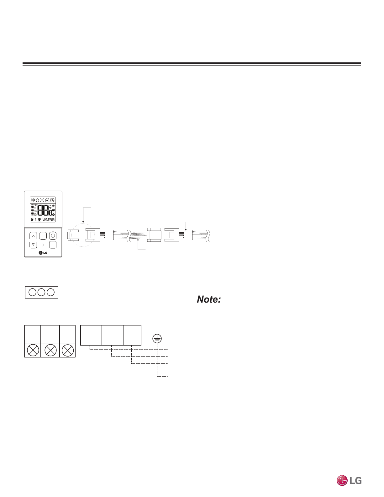
TWO-WAY VAHU INDOOR UNITS
Installation and Best Layout Practices
Indoor Unit Terminal Block
1(L1 )2(L2)
GND
3
Branch Distribution Unit
GRN /
YLW
BR
BL
RD
CN-REMO
YL
RD BK
Comm.
12V
Power
Ground
Figure 237:PZCWRC1 LG Wired Remote Extension Cable.
Controller Options
Vertical-Horizontal Air Handling indoor units can be used with many LG-supplied wired controllers (sold separately). The wireless handheld
controller (Model No. PQWRHQ0FDB) is also an optional accessory with use of the wired controller.
Verify the connectors are properly inserted.
C/BOX Cable (Plug type)
Extension cable
To Indoor Unit
CN-REMO
Terminal
TEMP
FAN
SPEED
OPER
MODE
Figure 238:Wired Controller Connection on the Indoor Unit Terminal Block.
When using eld-supplied controller cable, make sure to connect
the yellow to yellow (communications wire), red to red (12V power
wire), and black to black (ground wire) terminals from the remote
controller to the indoor unit terminal blocks.
Wired Controller Connections
Controllers can connect to the indoor unit in one of two different ways.
1. LG Wired Remote Extension Cable with Molex plug (PZCWRC1; sold separately) that connects to the CN-REMO terminal on the indoor
unit PCB.
2. Field-supplied controller cable that connects to the indoor unit terminal block (must be at least UL2547 or UL1007, 22 AWG, two-core,
one-shield core, at least FT-6 rated if local electric and building codes require plenum cable usage).
Due to our policy of continuous product innovation, some specications may change without notication.
©LG Electronics U.S.A., Inc., Englewood Cliffs, NJ. All rights reserved. “LG” is a registered trademark of LG Corp.
176 | VERTICAL-HORIZONTAL
Multi F and Multi F MAX Indoor Unit Engineering Manual
MULTI
F
MAX
MULTI
F

Figure 239:Proper Location for the Wired Controller.
4 to 5 feet
above the floor
NO
NO
NO
YES
Remote Controller
TEMP
Remote Controller
TEMP
Re
m
ot
e Co
nt
rol
l
er
TEMP
Wired controllers include a sensor to detect room temperature. To maintain
comfort levels in the conditioned space, the wired controller must be installed in
a location away from direct sunlight, high humidity, and where it could be directly
exposed to cold air. Controller must be installed four (4) to five (5) feet above the
floor where its LED display can be read easily, in an area with good air circula-
tion, and where it can detect an average room temperature.
Do not install the wired controller near or in:
• Drafts or dead spots behind doors and in corners
• Hot or cold air from ducts
• Radiant heat from the sun or appliances
• Concealed pipes and chimneys
• An area where temperatures are uncontrolled, such as an outside wall
Wired Controller Placement
Assigning the Thermistor for Temperature Detection
Each indoor unit includes a return air thermistor assigned to sense the temperature. If a wired controller is installed, there is a choice of
sensing temperature with either the indoor unit return air thermistor or the thermistor in the wired controller. It is also an option to set both
thermistors to sense temperature so that indoor unit bases its operation on the first thermistor to reach the designated temperature differen-
tial. For applicable indoor units, an optional Remote Temperature Sensor can be used in lieu of the return air thermistor—either alone or in
conjunction with a wired controller thermistor as previously described.
Hanging the Wired Controller
1. The controller wiring / cable can be installed in one of three directions: top,
back, or on the right side. If top or right side installation is desired, remove
cable guide grooves on the controller, and then position wiring / cable on ap-
plicable side.
2. Choose and mark the area of installation, and then screw the wall plate into
place (using the provided parts). Install the controller wall plate to fit the elec-
trical box if one is present. Ensure that no gaps exist between the wall plate
and the wall itself.
3. Arrange wiring / cables so as not to interfere with the controller circuitry.
Position the wired controller on the wall plate. Snap into place by pressing the
bottom part of the wired controller onto the wall plate. Make sure that no gaps
exist between the wired controller and the wall plate on all sides.
4. To remove wired controller from the wall plate, insert a screwdriver into the
two holes at the bottom. Twist screwdriver to release controller. Do not
damage the controller components when removing.
Back
To p
To p
Right
Side
Right
Side
Wall Wall
Wall Wall
Installing the Controller
Removing the Controller
Figure 240:Removing the Cable Guide Grooves.
Figure 241:Attaching the
Wall Plate.
Figure 242:Installing /
Removing the Controller.
TWO-WAY VAHU INDOOR UNITS
Installation and Best Layout Practices
VERTICAL-HORIZONTAL | 177
Vertical-Horizontal Air Handling
Due to our policy of continuous product innovation, some specications may change without notication.
©LG Electronics U.S.A., Inc., Englewood Cliffs, NJ. All rights reserved. “LG” is a registered trademark of LG Corp.
MULTI
F
MAX
MULTI
F

Due to our policy of continuous product innovation, some specications may change without notication.
©LG Electronics U.S.A., Inc., Englewood Cliffs, NJ. All rights reserved. “LG” is a registered trademark of LG Corp.
178 | VERTICAL-HORIZONTAL
Multi F and Multi F MAX Indoor Unit Engineering Manual
MULTI
F
MAX
MULTI
F

FOUR-WAY
VERTICAL-HORIZONTAL
AIR HANDLING
INDOOR UNIT DATA
“Mechanical Specifications” on page 180
“General Data / Specifications” on page 181
“Dimensions” on page 182
“Cooling Capacity Table” on page 183
“Heating Capacity Table” on page 185
“External Static Pressure” on page 187
“Heater Capacities” on page 189
“Acoustic Data” on page 190
“Refrigerant Flow Diagram” on page 192
“Wiring Diagram” on page 193
“Factory Supplied Parts and Materials” on page 195
“Installation and Best Layout Practices” on page 196
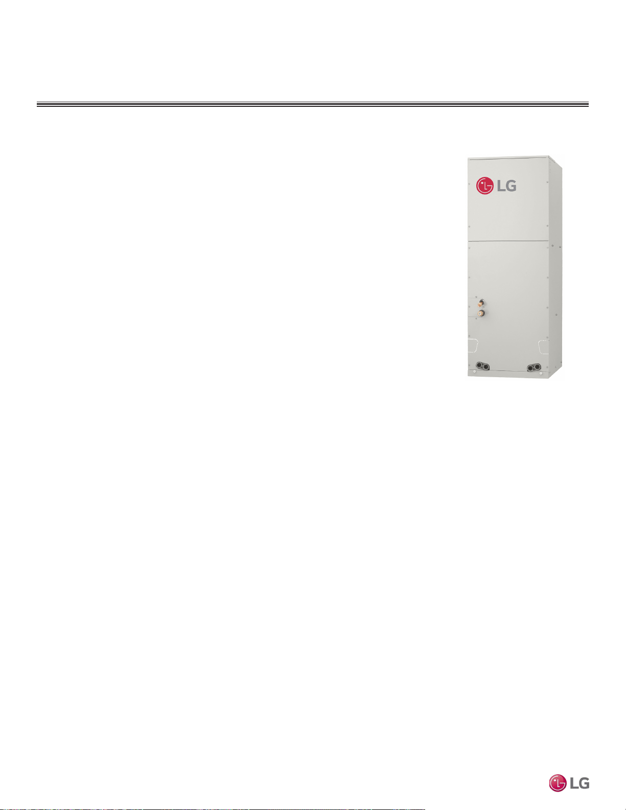
FOUR-WAY VAHU INDOOR UNITS
Mechanical Specications and Features
Four-way Vertical-Horizontal Air
Handing Indoor Unit
General
All LG indoor units are factory assembled, wired, piped, and provided
with a control circuit board, and constant CFM ECM fan. Vertical-
Horizontal Air Handling units are designed for high-speed air volume
against an external static pressure up to 0.7″WG. Supply air opening
is flanged to accept field-installed ductwork that cannot exceed the
external static pressure limit of the unit.
Coil
Indoor unit coils are factory built and are comprised of aluminum ns
mechanically bonded to copper tubing. Each unit has a minimum of
two rows of coils, which are pressure tested at the factory. Each unit is
provided with a factory installed condensate drain pan below the coil.
Refrigerant System
System is designed for use with R410A refrigerant. The refrigeration
circuit is pressure-tested at the factory and shipped with a holding
charge of helium gas. Refrigerant pipe connections are 45° flare,
and all refrigerant lines from the outdoor unit to the indoor units must
be field insulated.
Electrical
Each indoor unit is designed to operate using 208–230/60/1 power
with voltage variances of ±10%.
Casing
The casing is designed to mount fully concealed behind a wall or
above a finished ceiling. Casing is manufactured of 22-gauge metal
and finished with a high-gloss baked enamel finish. Cold surfaces of
the unit are covered internally with 1/2-inch polystyrene fiber insula-
tion; inside surface of the pan assembly door access panel is treated
with 1/2-inch polystyrene fiber insulation, encapsulated on both
sides. The access panel is sealed along the edges with reinforced
foil-faced covering, all access panels also have gasket seals to
minimize air leaks.
The vertical-horizontal air handling unit can operate in one of four
airflow configurations: vertical upflow, vertical downflow, horizon-
tal left discharge, or horizontal right discharge. Vertical downflow
operation requires an optional conversion kit. In the vertical position,
the unit has an opening for supply air from top (or bottom) with a
dedicated bottom (or top) vertical return. In the horizontal position,
supply air is from the left (or right) end with the return air from the
right (or left) end. Unit can also accept an internal, optional LG
electrical strip heater.
Fan Assembly and
Control
The units have an integral
fan assembly consisting of
galvanized steel housing and a
forward curve fan wheel. The ECM
(electronically commutated motor)
fan is programmed to deliver con-
stant CFM regardless of permitted
ESP (external static pressure),
and has permanently lubricated
and sealed ball bearings. The
fan / motor assembly is mounted
on vibration-attenuating rubber
grommets. Fan speed is controlled
using a microprocessor-based
direct digital control algorithm. The
indoor fan has Low, Med, High,
and Auto settings for Cooling
mode; and has Low, Med, High,
and Auto settings for Heating
mode. Low, Med and High fan
speeds maintain published airow
as the ECM motor adjusts to ESP. The Auto setting adjusts the fan
speed to most effectively achieve setpoint.
Filter Assembly
The unit comes with a filter rack sized to hold a field-provided 16”
x 20” x 1” filter cartridge. The filter rack has a guide to assist in
centering the filters, and can be accessed from the front.
Microprocessor Control
The indoor unit is provided with an integrated control board to
communicate with the outdoor unit. All unit operation parameters
are stored in non-volatile memory resident on the unit microproces-
sor. The microprocessor controls space temperature through using
the value provided by temperature sensors within the indoor unit. A
field-supplied communication cable must be installed to connect the
indoor unit(s) to the outdoor unit.
Controls
The indoor unit controller of choice must be ordered separately.
Communication between the indoor units and the outdoor unit is ac-
complished through 14 AWG, four-core, stranded and shielded power
/ communication cable. The indoor unit has a built-in dry contact for a
eld supplied 3rd party thermostat. An optional Wi-Fi module is avail-
able as an additional accessory for use with LG’s Smart ThinQ app on
a smart device.
Condensate
The unit is designed for gravity draining of condensate.
• Inverter (Variable speed fan)
• Control lock function
• Auto operation
• Dehumidifying function
• Two thermistor control
• Group control
• Optional accessory electric heater
• Self-diagnostics function
• Built-in dry contact for third party
thermostat
• Wired controller ordered separately
• Constant CFM ECM fan
Features
Figure 243: Multi F Vertical-Horizontal
Air Handling Indoor Unit.
Due to our policy of continuous product innovation, some specications may change without notication.
©LG Electronics U.S.A., Inc., Englewood Cliffs, NJ. All rights reserved. “LG” is a registered trademark of LG Corp.
180 | VERTICAL-HORIZONTAL
Multi F and Multi F MAX Indoor Unit Engineering Manual
MULTI
F
MAX
MULTI
F
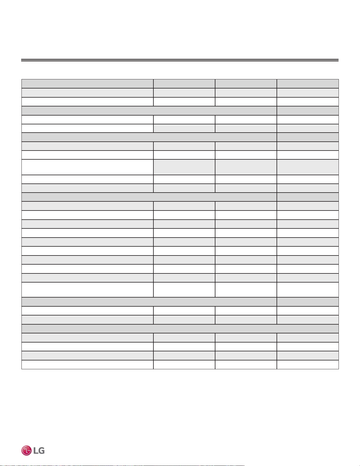
General Data / Specications
FOUR-WAY VAHU INDOOR UNITS
Model Name LVN181HV4 LVN241HV4 LVN361HV4
Nominal Cooling Capacity (Btu/h)
1
18,000 24,000 36,000
Nominal Heating Capacity (Btu/h)
1
20,000 27,000 40,000
Operating Range
Cooling (°F WB)
57-77 57-77 57-77
Heating (°F DB)
59-81 59-81 59-81
Fan
Type
Sirocco Sirocco Sirocco
Motor Output (W) x Qty.
250 x 1 250 x 1 250 x 1
Motor/Drive
ECM (Electronically
Commutated Motor) / Direct
ECM (Electronically
Commutated Motor) / Direct
ECM (Electronically
Commutated Motor) / Direct
Airflow Rate CFM (H/M/L)
640 / 580 / 480 710 / 640 / 480 990 / 880 / 800
Maximum External Static Pressure (in. WG)
0.7 0.7 0.7
Unit Data
Refrigerant Type
2
R410A R410A R410A
Refrigerant Control
EEV EEV EEV
Power Supply V, Ø, Hz
3
208-230, 1, 60 208-230, 1, 60 208-230, 1, 60
Rated Amps (A)
1.1 1.1 1.1
Sound Pressure Level dB(A) (H/M/L)
4
at 0.3"WG ESP
35 / 33 / 30 36 / 34 / 30 44 / 41 / 39
Dimensions (W x H x D, in.)
18 x 48-11/16 x 21-1/4 18 x 48-11/16 x 21-1/4 18 x 48-11/16 x 21-1/4
Net Weight (lbs.)
123.5 123.5 129
Shipping Weight (lbs.)
135.1 135.1 140
Power Wiring / Communications Cable (No. x AWG)
5
4 x 14 4 x 14 4 x 14
Heat Exchanger
(Row x Column x Fin / inch) x Number
(2x24x18)x2 (2x24x18)x2 (3x24x18)x2
Pipe Size
Liquid (in.)
1/4 1/4 3/8
Vapor (in.)
1/2 1/2 5/8
Connection Size
Liquid (in.)
3/8 3/8 3/8
Vapor (in.)
5/8 5/8 5/8
Primary Drain I.D. (in.)
3/4 FPT 3/4 FPT 3/4 FPT
Secondary Drain I.D. (in.)
3/4 FPT 3/4 FPT 3/4 FPT
Table 93: Multi F Vertical-Horizontal Air Handling Indoor Unit General Data.
1
Nominal capacity is rated 0 ft. above sea level with corresponding refrigerant piping length in
accordance with standard length of each outdoor unit and a 0 ft. level difference between outdoor and
indoor units. All capacities are net with a combination ratio between 95 – 105%.
Nominal cooling capacity rating obtained with air entering the indoor unit at 80ºF dry bulb (DB) and 67ºF
wet bulb (WB) and outdoor ambient conditions of 95ºF dry bulb (DB) and 75ºF wet bulb (WB).
Nominal heating capacity rating obtained with air entering the indoor unit at 70ºF dry bulb (DB) and 60ºF
wet bulb (WB) and outdoor ambient conditions of 47ºF dry bulb (DB) and 43ºF wet bulb (WB).
2
This unit comes with a dry helium charge.
3
Acceptable operating voltage: 187V-253V.
4
Sound pressure levels are tested in an anechoic chamber under ISO Standard 3745 and are the
same in both cooling and heating mode. These values can increase due to ambient conditions during
operation.
5
All power wiring / communications cable to the IDUs must be minimum 14 AWG, 4-conductor, stranded,
shielded or unshielded (if shielded, must be grounded to chassis at ODU only) and must comply with
applicable local and national codes.
VERTICAL-HORIZONTAL | 181
Vertical-Horizontal Air Handling Unit
Due to our policy of continuous product innovation, some specications may change without notication.
©LG Electronics U.S.A., Inc., Englewood Cliffs, NJ. All rights reserved. “LG” is a registered trademark of LG Corp.
MULTI
F
MAX
MULTI
F
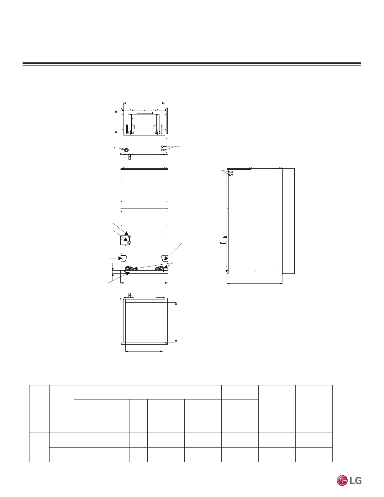
Dimensions
FOUR-WAY VAHU INDOOR UNITS
Figure 244: Four-way Vertical Air Handling Unit Dimensions.
Top
Front
Bottom
Side-right
Refrigerant
connections
Drain connections
for horizontal left
application
Drain
connections
for upflow
application
Air filter cover
Unit: inch
ODU
Capacity
(kBtu/h)
Dimensions
Wiring
Knock out
Refrigerant
Pipe size
A B C
D E F G H
I J
Height Width Depth
Power
Comm-
unication
Liquid Gas
Multi
Zone
18
24
48-11/16 18 21-1/4 1-9/16 17-1/2 20 17 12-1/8 1-11/16 7/8 1/4 1/2
36
48-11/16 18 21-1/4 1-9/16 17-1/2 20 17 12-1/8 1-11/16 7/8 3/8 5/8
G
J
C
J
B
I
E
F
D
A
H
Drain connections
for horizontal right
application
Refrigerant
Connections
Pipe
Liquid Gas
3/8 5/8
3/8 5/8
Due to our policy of continuous product innovation, some specications may change without notication.
©LG Electronics U.S.A., Inc., Englewood Cliffs, NJ. All rights reserved. “LG” is a registered trademark of LG Corp.
182 | VERTICAL-HORIZONTAL
Multi F and Multi F MAX Indoor Unit Engineering Manual
MULTI
F
MAX
MULTI
F
Cooling Capacity Table
FOUR-WAY VAHU INDOOR UNITS
Table 94: Multi F Vertical-Horizontal Air Handling Indoor Units Cooling Capacity Table.
TC = Total Capacity (kBtu/h).
SHC: Sensible Heat Capacity (kBtu/h).
Nominal capacity as rated 0 ft. above sea level and a 0 ft. level difference between outdoor and indoor units. Corresponding refrigerant piping length is accordance with standard length of each outdoor unit.
Nominal cooling capacity rating obtained with air entering the indoor unit at 80ºF dry bulb (DB) and 67ºF wet bulb (WB), and outdoor ambient conditions of 95ºF dry bulb (DB) and 75ºF wet bulb (WB).
The shaded table columns and rows indicate reference data. When operating at this temperature, these values can be different if the system is not running consistently.
Model No. /
Nominal Capacity
of Indoor Unit
(Btu/h)
Outdoor Air
Temp.
(°F DB)
Indoor Air Temp. °F DB / °F WB
68 / 57 73 / 61 77 / 64 80 / 67 86 / 72 90 / 75
TC SHC TC SHC TC SHC TC SHC TC SHC TC SHC
LVN181HV4
18,000
14 17.65 13.25 18.74 13.99 19.84 13.55 20.63 13.83 22.03 13.95 23.12 14.22
20 17.63 13.35 18.73 14.10 19.82 13.65 20.61 13.94 22.01 14.06 23.11 14.33
25 17.62 13.45 18.71 14.21 19.81 13.76 20.60 14.05 22.00 14.17 23.09 14.44
30 17.60 13.56 18.70 14.32 19.79 13.87 20.58 14.16 21.98 14.28 23.07 14.55
35 17.59 13.66 18.68 14.43 19.78 13.97 20.57 14.27 21.96 14.39 23.05 14.66
40 17.58 13.76 18.67 14.54 19.76 14.08 20.55 14.37 21.94 14.49 23.04 14.77
45 17.56 13.87 18.66 14.65 19.75 14.18 20.53 14.48 21.93 14.60 23.02 14.88
50 17.55 13.97 18.64 14.75 19.73 14.29 20.52 14.59 21.91 14.71 23.00 14.99
55 17.54 14.07 18.63 14.86 19.72 14.39 20.50 14.69 21.89 14.82 22.98 15.10
60 17.52 14.17 18.61 14.97 19.70 14.50 20.49 14.80 21.88 14.93 22.97 15.21
65 17.51 14.27 18.60 15.08 19.69 14.60 20.47 14.91 21.86 15.03 22.95 15.32
70 17.50 14.38 18.58 15.19 19.67 14.70 20.46 15.01 21.84 15.14 22.93 15.43
75 17.08 14.14 18.16 14.96 19.24 14.50 20.03 14.81 21.41 14.96 22.50 15.25
80 16.66 13.90 17.74 14.72 18.82 14.29 19.60 14.61 20.98 14.77 22.06 15.07
85 16.24 13.64 17.32 14.47 18.40 14.06 19.17 14.39 20.55 14.57 21.63 14.88
90 15.82 13.39 16.90 14.22 17.97 13.84 18.75 14.17 20.12 14.36 21.20 14.69
95 15.37 13.25 16.44 14.09 17.51 13.73 18.00 13.86 19.65 14.29 20.72 14.62
100 14.99 12.89 16.06 13.74 17.13 13.40 17.77 13.65 19.28 13.98 20.35 14.32
105 14.62 12.54 15.69 13.38 16.76 13.08 17.53 13.43 18.90 13.67 19.97 14.02
110 14.24 12.11 15.32 12.95 16.39 12.67 17.16 13.03 18.53 13.29 19.60 13.64
115 13.87 11.75 14.94 12.58 16.01 12.34 16.79 12.70 18.15 12.97 19.22 13.33
118 13.65 11.66 14.72 12.51 15.79 12.27 16.56 12.64 17.93 12.92 19.00 13.29
122 13.57 11.63 14.64 12.48 15.71 12.25 16.49 12.62 17.85 12.91 18.92 13.28
LVN241HV4
24,000
14 23.53 17.89 24.99 18.90 26.45 18.30 27.50 18.69 29.37 18.84 30.83 19.20
20 23.51 18.03 24.97 19.05 26.43 18.44 27.48 18.83 29.35 18.99 30.81 19.35
25 23.49 18.17 24.95 19.20 26.41 18.59 27.46 18.98 29.33 19.14 30.79 19.50
30 23.47 18.31 24.93 19.34 26.39 18.73 27.44 19.12 29.30 19.28 30.76 19.65
35 23.46 18.45 24.91 19.49 26.37 18.87 27.42 19.27 29.28 19.43 30.74 19.80
40 23.44 18.59 24.89 19.64 26.35 19.01 27.40 19.41 29.26 19.58 30.72 19.95
45 23.42 18.73 24.87 19.78 26.33 19.15 27.38 19.56 29.24 19.72 30.69 20.10
50 23.40 18.87 24.85 19.93 26.31 19.30 27.36 19.70 29.21 19.87 30.67 20.24
55 23.38 19.00 24.84 20.07 26.29 19.44 27.34 19.85 29.19 20.01 30.64 20.39
60 23.37 19.14 24.82 20.22 26.27 19.58 27.32 19.99 29.17 20.16 30.62 20.54
65 23.35 19.28 24.80 20.37 26.25 19.72 27.29 20.13 29.15 20.30 30.60 20.69
70 23.33 19.42 24.78 20.51 26.23 19.86 27.27 20.28 29.13 20.45 30.57 20.84
75 22.77 19.10 24.21 20.20 25.66 19.58 26.70 20.01 28.55 20.20 29.99 20.60
80 22.21 18.77 23.65 19.88 25.09 19.30 26.13 19.73 27.97 19.95 29.42 20.36
85 21.65 18.43 23.09 19.55 24.53 18.99 25.57 19.44 27.40 19.68 28.84 20.10
90 21.09 18.08 22.53 19.21 23.96 18.69 25.00 19.14 26.83 19.40 28.27 19.84
95 20.49 17.89 21.92 19.03 23.35 18.55 24.00 18.72 26.20 19.30 27.63 19.75
100 19.99 17.41 21.42 18.55 22.85 18.10 23.69 18.43 25.70 18.88 27.13 19.35
105 19.49 16.93 20.92 18.07 22.35 17.66 23.38 18.14 25.20 18.47 26.63 18.94
110 18.99 16.35 20.42 17.49 21.85 17.12 22.88 17.60 24.70 17.94 26.13 18.42
115 18.49 15.86 19.92 17.00 21.35 16.66 22.38 17.15 24.20 17.51 25.63 18.00
118 18.19 15.75 19.62 16.89 21.05 16.58 22.08 17.07 23.90 17.46 25.33 17.96
122 18.10 15.71 19.52 16.86 20.95 16.55 21.98 17.05 23.81 17.44 25.23 17.94
VERTICAL-HORIZONTAL | 183
Vertical-Horizontal Air Handling Unit
Due to our policy of continuous product innovation, some specications may change without notication.
©LG Electronics U.S.A., Inc., Englewood Cliffs, NJ. All rights reserved. “LG” is a registered trademark of LG Corp.
MULTI
F
MAX
MULTI
F
Table 95: Multi F Vertical-Horizontal Air Handling Indoor Units Cooling Capacity Table - continued
TC = Total Capacity (kBtu/h).
SHC: Sensible Heat Capacity (kBtu/h).
Nominal capacity as rated 0 ft. above sea level and a 0 ft. level difference between outdoor and indoor units. Corresponding refrigerant piping length is accordance with standard length of each outdoor unit.
Nominal cooling capacity rating obtained with air entering the indoor unit at 80ºF dry bulb (DB) and 67ºF wet bulb (WB), and outdoor ambient conditions of 95ºF dry bulb (DB) and 75ºF wet bulb (WB).
The shaded table columns and rows indicate reference data. When operating at this temperature, these values can be different if the system is not running consistently.
Model No. /
Nominal Capacity
of Indoor Unit
(Btu/h)
Outdoor Air
Temp.
(°F DB)
Indoor Air Temp. °F DB / °F WB
68 / 57 73 / 61 77 / 64 80 / 67 86 / 72 90 / 75
TC SHC TC SHC TC SHC TC SHC TC SHC TC SHC
LVN361HV4
18,000
14 35.29 27.18 37.48 28.71 39.67 27.80 41.26 28.39 44.06 28.63 46.25 29.17
20 35.26 27.39 37.45 28.94 39.64 28.02 41.23 28.61 44.02 28.85 46.21 29.40
25 35.24 27.61 37.43 29.16 39.61 28.24 41.19 28.83 43.99 29.07 46.18 29.62
30 35.21 27.82 37.40 29.39 39.58 28.45 41.16 29.05 43.96 29.30 46.14 29.85
35 35.18 28.03 37.37 29.61 39.55 28.67 41.13 29.27 43.92 29.52 46.11 30.08
40 35.16 28.24 37.34 29.83 39.52 28.88 41.10 29.49 43.89 29.74 46.07 30.30
45 35.13 28.45 37.31 30.05 39.49 29.10 41.07 29.71 43.86 29.96 46.04 30.53
50 35.10 28.66 37.28 30.28 39.46 29.32 41.04 29.93 43.82 30.19 46.00 30.76
55 35.08 28.87 37.25 30.50 39.43 29.53 41.01 30.15 43.79 30.41 45.97 30.98
60 35.05 29.08 37.23 30.72 39.40 29.74 40.97 30.37 43.76 30.63 45.93 31.21
65 35.02 29.29 37.20 30.94 39.37 29.96 40.94 30.59 43.72 30.85 45.90 31.43
70 34.99 29.50 37.17 31.16 39.34 30.17 40.91 30.81 43.69 31.07 45.86 31.66
75 34.15 29.01 36.32 30.69 38.49 29.75 40.05 30.40 42.82 30.69 44.99 31.30
80 33.31 28.52 35.47 30.20 37.64 29.31 39.20 29.98 41.96 30.30 44.12 30.93
85 32.48 28.00 34.63 29.70 36.79 28.86 38.35 29.53 41.10 29.89 43.26 30.54
90 31.64 27.47 33.79 29.18 35.94 28.39 37.50 29.08 40.25 29.48 42.40 30.14
95 30.74 27.18 32.88 28.92 35.02 28.17 36.00 28.44 39.30 29.32 41.44 30.01
100 29.99 26.45 32.13 28.19 34.27 27.50 35.53 28.00 38.55 28.69 40.69 29.39
105 29.24 25.72 31.38 27.46 33.52 26.83 35.07 27.56 37.80 28.06 39.94 28.78
110 28.49 24.84 30.63 26.57 32.77 26.00 34.32 26.74 37.05 27.26 39.20 27.99
115 27.74 24.10 29.88 25.82 32.02 25.31 33.57 26.05 36.31 26.61 38.45 27.35
118 27.29 23.93 29.43 25.66 31.57 25.19 33.12 25.94 35.86 26.52 38.00 27.28
122 27.14 23.87 29.28 25.61 31.43 25.14 32.97 25.90 35.71 26.49 37.85 27.25
Cooling Capacity Table
FOUR-WAY VAHU INDOOR UNITS
Due to our policy of continuous product innovation, some specications may change without notication.
©LG Electronics U.S.A., Inc., Englewood Cliffs, NJ. All rights reserved. “LG” is a registered trademark of LG Corp.
184 | VERTICAL-HORIZONTAL
Multi F and Multi F MAX Indoor Unit Engineering Manual
MULTI
F
MAX
MULTI
F
Table 95: Multi F Vertical-Horizontal Air Handling Indoor Units Heating Capacity Table.
Model No. /
Nominal Capacity
of Indoor Unit
(Btu/h)
Outdoor Air Temp. Indoor Air Temp. °F DB
°F DB °F WB
61 64 68 70 72 75
TC TC TC TC TC TC
LVN181HV4
18,000
0 -0.4 10.29 10.14 10.05 10.00 9.86 9.42
5 4.5 11.59 11.45 11.35 11.30 11.16 10.72
10 9 12.90 12.75 12.66 12.61 12.46 12.03
17 15 14.64 14.49 14.40 14.35 14.20 13.74
20 19 15.29 15.14 15.05 15.00 14.86 14.35
25 23 16.38 16.23 16.14 16.09 15.94 15.36
30 28 17.32 17.17 17.08 17.03 16.88 16.38
35 32 18.26 18.12 18.02 17.97 17.83 17.39
40 36 19.11 18.96 18.86 18.82 18.67 18.24
45 41 19.95 19.81 19.71 19.66 19.52 19.08
47 43 20.29 20.14 20.05 20.00 19.86 19.42
50 46 20.62 20.47 20.37 20.33 20.18 19.69
55 51 21.16 21.01 20.92 20.87 20.72 20.14
60 56 21.16 21.01 20.92 20.87 20.72 20.24
63 59 21.16 21.01 20.92 20.87 20.72 20.29
68 64 21.16 21.01 20.92 20.87 20.72 20.38
LVN241HV4
24,000
0 -0.4 13.89 13.70 13.57 13.50 13.30 12.72
5 4.5 15.65 15.46 15.33 15.26 15.07 14.48
10 9 17.41 17.22 17.09 17.02 16.83 16.24
17 15 19.76 19.57 19.43 19.37 19.17 18.55
20 19 20.64 20.45 20.32 20.25 20.05 19.37
25 23 22.11 21.91 21.78 21.72 21.52 20.74
30 28 23.38 23.18 23.05 22.99 22.79 22.11
35 32 24.65 24.46 24.33 24.26 24.07 23.48
40 36 25.79 25.60 25.47 25.40 25.21 24.62
45 41 26.93 26.74 26.61 26.54 26.35 25.76
47 43 27.39 27.20 27.07 27.00 26.80 26.22
50 46 27.83 27.64 27.51 27.44 27.24 26.58
55 51 28.57 28.37 28.24 28.17 27.98 27.20
60 56 28.57 28.37 28.24 28.17 27.98 27.32
63 59 28.57 28.37 28.24 28.17 27.98 27.39
68 64 28.57 28.37 28.24 28.17 27.98 27.51
FOUR-WAY VAHU INDOOR UNITS
Heating Capacity Table
TC = Total Capacity (kBtu/h).
Nominal capacity as rated 0 ft. above sea level and a 0 ft. level difference between outdoor and indoor units. Corresponding refrigerant piping length is accordance with standard length of each outdoor unit.
Nominal heating capacity rating obtained with air entering the indoor unit at 70ºF dry bulb (DB) and 60ºF wet bulb (WB), and outdoor ambient conditions of 47ºF dry bulb (DB) and 43ºF wet bulb (WB).
VERTICAL-HORIZONTAL | 185
Vertical-Horizontal Air Handling Unit
Due to our policy of continuous product innovation, some specications may change without notication.
©LG Electronics U.S.A., Inc., Englewood Cliffs, NJ. All rights reserved. “LG” is a registered trademark of LG Corp.
MULTI
F
MAX
MULTI
F
Model No. /
Nominal Capacity
of Indoor Unit
(Btu/h)
Outdoor Air Temp. Indoor Air Temp. °F DB
°F DB °F WB
61 64 68 70 72 75
TC TC TC TC TC TC
LVN361HV4
36,000
0 -0.4 20.58 20.29 20.10 20.00 19.71 18.84
5 4.5 23.19 22.90 22.71 22.61 22.32 21.45
10 9 25.80 25.51 25.31 25.22 24.93 24.06
17 15 29.28 28.99 28.79 28.70 28.41 27.48
20 19 30.58 30.29 30.10 30.00 29.71 28.70
25 23 32.75 32.46 32.27 32.17 31.88 30.72
30 28 34.64 34.35 34.15 34.06 33.77 32.75
35 32 36.52 36.23 36.04 35.94 35.65 34.78
40 36 38.21 37.92 37.73 37.63 37.34 36.47
45 41 39.90 39.61 39.42 39.32 39.03 38.16
47 43 40.58 40.29 40.10 40.00 39.71 38.84
50 46 41.23 40.94 40.75 40.65 40.36 39.38
55 51 42.32 42.03 41.84 41.74 41.45 40.29
60 56 42.32 42.03 41.84 41.74 41.45 40.47
63 59 42.32 42.03 41.84 41.74 41.45 40.58
68 64 42.32 42.03 41.84 41.74 41.45 40.76
TC = Total Capacity (kBtu/h).
Nominal capacity as rated 0 ft. above sea level and a 0 ft. level difference between outdoor and indoor units. Corresponding refrigerant piping length is accordance with standard length of each outdoor unit.
Nominal heating capacity rating obtained with air entering the indoor unit at 70ºF dry bulb (DB) and 60ºF wet bulb (WB), and outdoor ambient conditions of 47ºF dry bulb (DB) and 43ºF wet bulb (WB).
Table 96: Multi F Vertical-Horizontal Air Handling Indoor Units Heating Capacity Table - continued
FOUR-WAY VAHU INDOOR UNITS
Heating Capacity Table
Due to our policy of continuous product innovation, some specications may change without notication.
©LG Electronics U.S.A., Inc., Englewood Cliffs, NJ. All rights reserved. “LG” is a registered trademark of LG Corp.
186 | VERTICAL-HORIZONTAL
Multi F and Multi F MAX Indoor Unit Engineering Manual
MULTI
F
MAX
MULTI
F

External Static Pressure
FOUR-WAY VAHU INDOOR UNITS
Capacity (kBtu/h [tons]) Flow Rate (CFM) Static Pressure Drop (in wg)
18 (1.5)
High (640) -0.04
Middle(580) -0.04
Low (480) -0.04
24 (2.0)
High (710) -0.04
Middle(640) -0.04
Low (480) -0.04
36 (3.0)
High (990) -0.04
Middle(880) -0.04
Low (800) -0.04
Table 96: Air Filter Static Pressure Drop Factors.
Capacity (kBtu/h [tons])
Heater Capacity kW
3, 5 8, 10 15 20
18 (1.5)
480 480 Not Available Not Available
24 (2.0)
480 480 Not Available Not Available
36 (3.0)
900 900 Not Available Not Available
Table 97: Minimum Airow (CFM) by Heater Capacity
Do not operate with less than the minimum airow. If an airow
is used below the minimum, there is a risk of re, which will
lead to physical injury or death
Note:
Do not operate with less than the minimum airow. If an airow is
used below the minimum, there is a risk of damage to the product.
These VAHUs are constant air volume (CAV) units and do not require any
eld adjustment to change ESP settings.
VERTICAL-HORIZONTAL | 187
Vertical-Horizontal Air Handling Unit
Due to our policy of continuous product innovation, some specications may change without notication.
©LG Electronics U.S.A., Inc., Englewood Cliffs, NJ. All rights reserved. “LG” is a registered trademark of LG Corp.
MULTI
F
MAX
MULTI
F
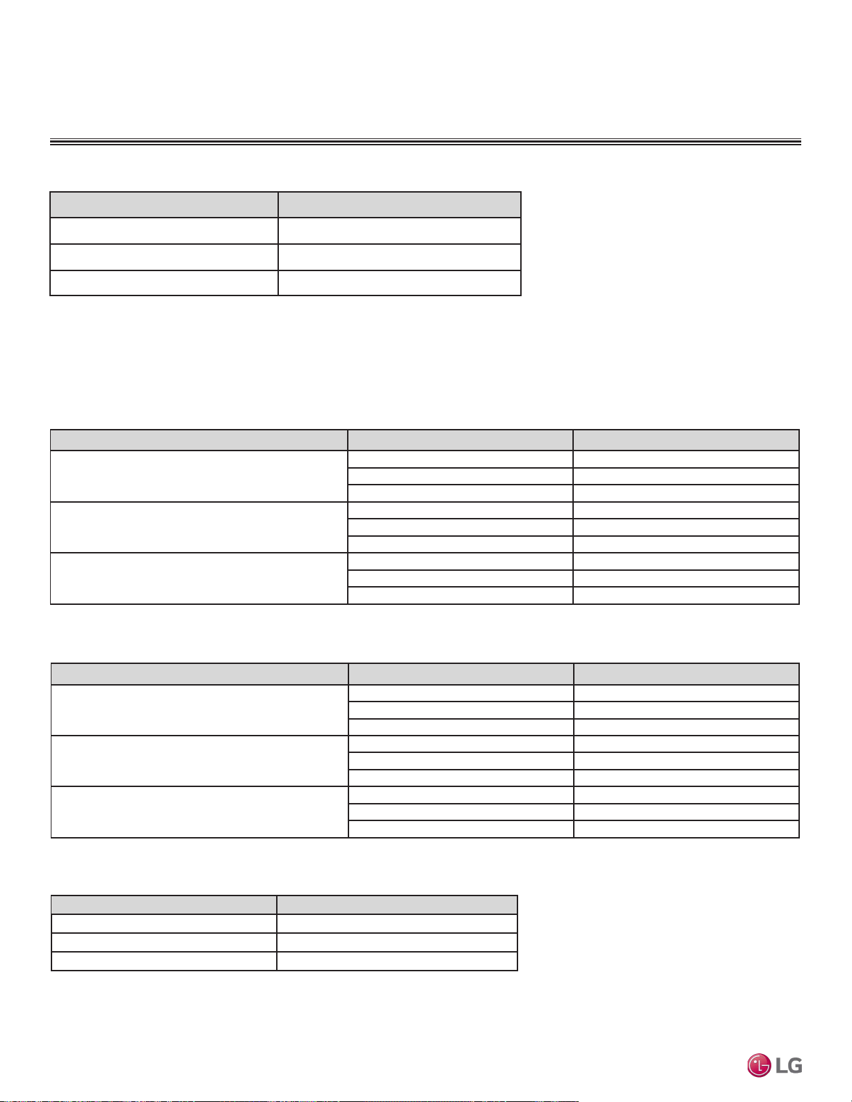
External Static Pressure
FOUR-WAY VAHU INDOOR UNITS
Heater Capacity Static Pressure Drop (in. wg)
0 0
3, 5 -0.01
8, 10 -0.02
Table 98: Electric Heater Static Pressure Drop Factors.
Capacity (kBtu/h [tons]) Flow Rate (CFM) Static Pressure Drop (in wg)
18 (1.5)
High (640) -0.04
Middle(580) -0.04
Low (480) -0.04
24 (2.0)
High (710) -0.04
Middle(640) -0.04
Low (480) -0.04
36 (3.0)
High (990) -0.04
Middle(880) -0.04
Low (800) -0.04
Table 99: Down Flow (optional) Static Pressure Drop Factors.
Capacity (kBtu/h [tons]) Flow Rate (CFM) Static Pressure Drop (in wg)
18 (1.5)
High (640) -0.04
Middle(580) -0.04
Low (480) -0.04
24 (2.0)
High (710) -0.04
Middle(640) -0.04
Low (480) -0.04
36 (3.0)
High (990) -0.04
Middle(880) -0.04
Low (800) -0.04
Table 100: Down Flow Air Filter Static Pressure Drop Factors
Heater Capacity (kW) Static Pressure Drop (in. wg)
0 0
3, 5 -0.01
8, 10 -0.01
Table 101: Down Flow Internal Electric Heater Static Pressure Drop.
Due to our policy of continuous product innovation, some specications may change without notication.
©LG Electronics U.S.A., Inc., Englewood Cliffs, NJ. All rights reserved. “LG” is a registered trademark of LG Corp.
188 | VERTICAL-HORIZONTAL
Multi F and Multi F MAX Indoor Unit Engineering Manual
MULTI
F
MAX
MULTI
F
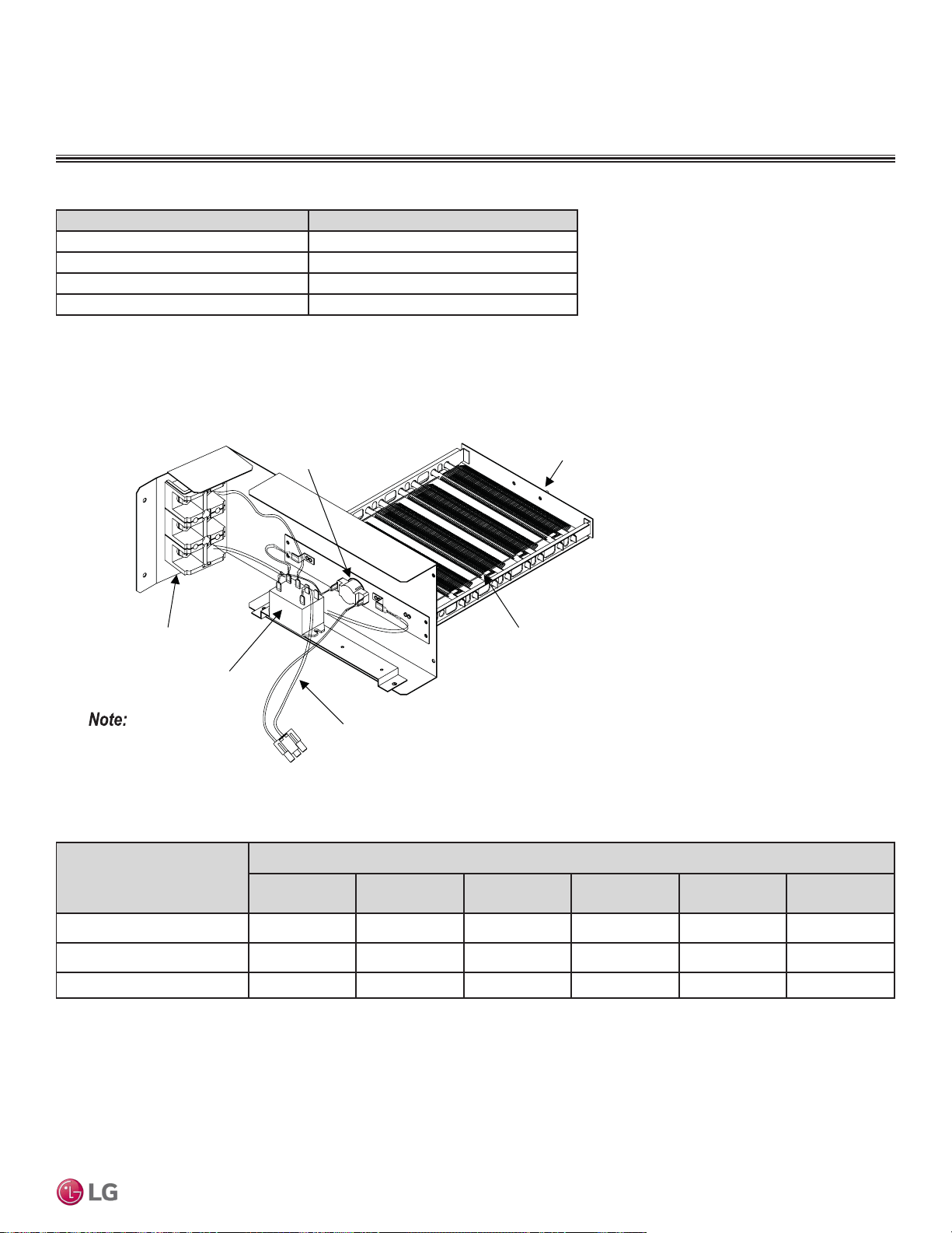
Heater Capacity (kW) Model Number
3
ANEH033B1
5
ANEH053B1
8
ANEH083B2
10
ANEH103B2
Table 102: Optional Electric Heater Capacities.
Figure 245: Typical Vertical Air Handling Unit Optional Electric Heater Accessory.
Example: 5kW Capacity Heater
Terminal Block
Relay
Heater Cable
Bi metal
Heater Coil
Bracket
Appearance may vary
depending on model capacity.
VAHU Model Number and
Capacity (MBh)
Model Number / Heater Capacity kW
ANEH033B1
(3kW)
ANEH053B1
(5kW)
ANEH083B2
(8kW)
ANEH103B2
(10kW)
ANEH153B2
(15kW)
ANEH203B2
(20kW)
LVN181HV4 (18)
√ √ √ √ X X
LVN241HV4 (24)
√ √ √ √ X X
LVN361HV4 (36)
√ √ √ √ X X
Table 103: Electric Heater Compatibility
√ = Compatible X = Not Compatible
FOUR-WAY VAHU INDOOR UNITS
Heater Capacities
VERTICAL-HORIZONTAL | 189
Vertical-Horizontal Air Handling Unit
Due to our policy of continuous product innovation, some specications may change without notication.
©LG Electronics U.S.A., Inc., Englewood Cliffs, NJ. All rights reserved. “LG” is a registered trademark of LG Corp.
MULTI
F
MAX
MULTI
F
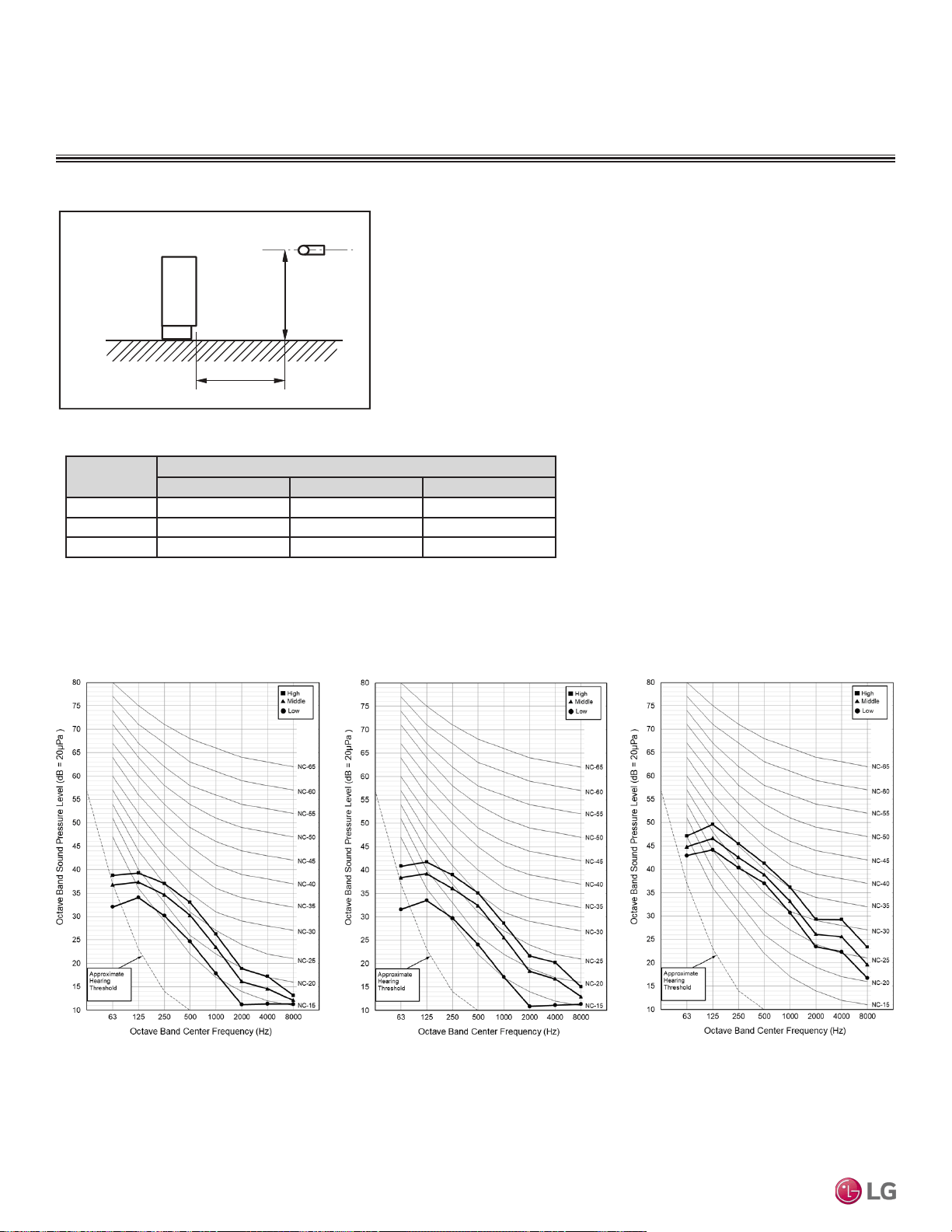
FOUR-WAY VAHU INDOOR UNITS
Acoustic Data
• Measurement taken 3.3′ away from the unit.
• Sound pressure levels are measured in dB(A).
• Sound pressure levels are tested in an anechoic chamber under ISO
Standard 3745.
• Operating Conditions:
Power source: 220V/60 Hz.
• Sound level will vary depending on a range of factors including the con-
struction (acoustic absorption coefficient) of a particular room in which
the unit was installed.
Figure 246: Sound Pressure Level Measurement Location.
Table 104: Vertical Air Handling Unit Sound Pressure Levels (dB[A]).
Figure 247: Sound Pressure Level Diagrams.
Model No.
Sound Pressure Levels (dB[A]) (Cooling and Heating)
High Fan Speed Medium Fan Speed Low Fan Speed
LVN181HV4 35 33 30
LVN241HV4 36 34 30
LVN361HV4 44 41 39
3.3 ft.
3.3 ft.
With Case
Microphone
LVN181HV4 LVN241HV4 LVN361HV4
Due to our policy of continuous product innovation, some specications may change without notication.
©LG Electronics U.S.A., Inc., Englewood Cliffs, NJ. All rights reserved. “LG” is a registered trademark of LG Corp.
190 | VERTICAL-HORIZONTAL
Multi F and Multi F MAX Indoor Unit Engineering Manual
MULTI
F
MAX
MULTI
F
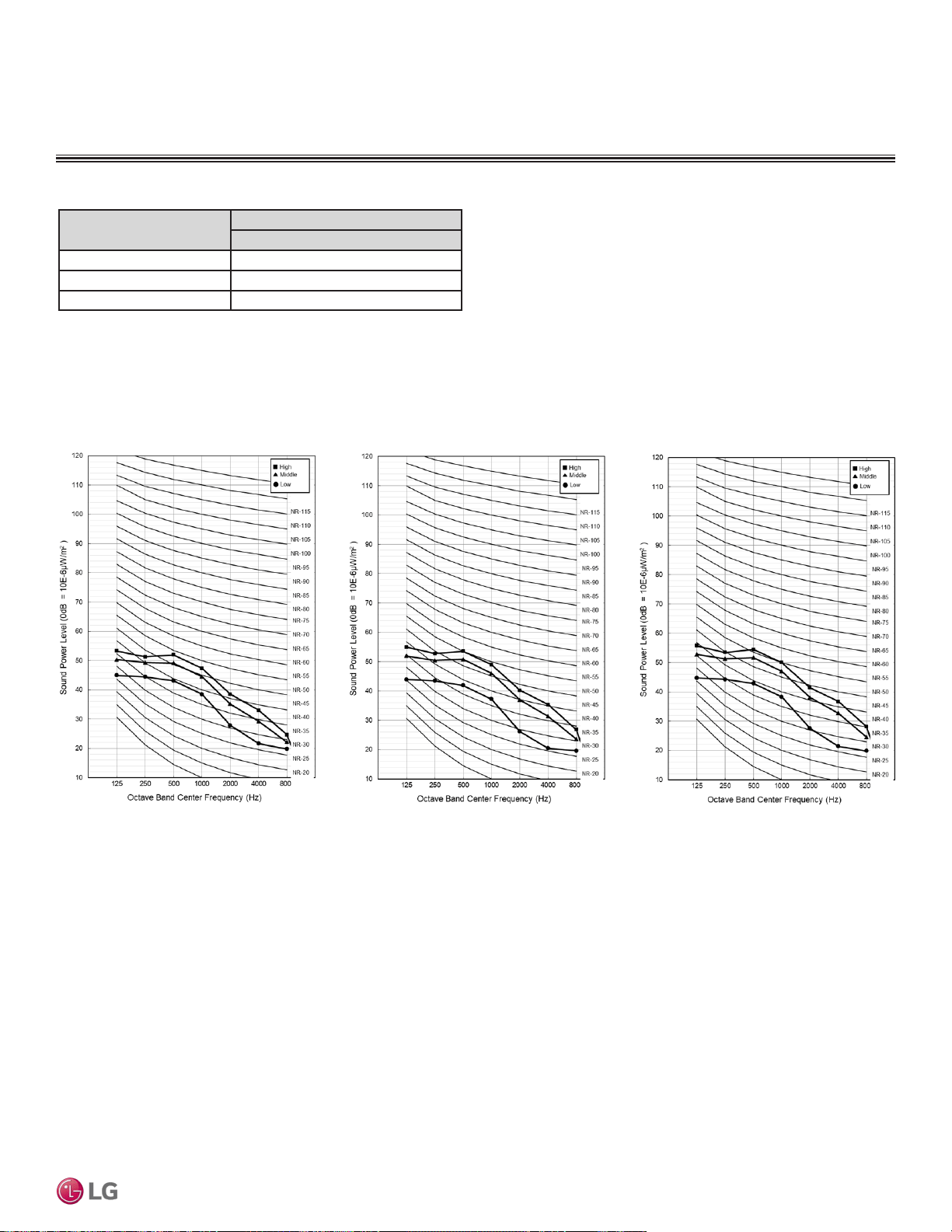
FOUR-WAY VAHU INDOOR UNITS
Acoustic Data
Table 105: Vertical Air Handling Unit Sound Power Levels (dB[A]).
Model No.
Sound Power Levels (dB[A])
High Fan Speed
LVN181HV4 54
LVN241HV4 55
LVN361HV4 63
• Data is valid under diffuse field conditions.
• Data is valid under nominal operating conditions.
• Sound power level is measured using rated conditions, and tested
in a reverberation room per ISO 3741 standards.
• Sound level will vary depending on a range of factors such as
construction (acoustic absorption coefficient) of particular area in
which the equipment is installed.
• Reference acoustic intensity: 0dB = 10E-6μW/m2
Figure 248: Sound Power Level Diagrams.
LVN181HV4 LVN241HV4 LVN361HV4
VERTICAL-HORIZONTAL | 191
Vertical-Horizontal Air Handling Unit
Due to our policy of continuous product innovation, some specications may change without notication.
©LG Electronics U.S.A., Inc., Englewood Cliffs, NJ. All rights reserved. “LG” is a registered trademark of LG Corp.
MULTI
F
MAX
MULTI
F
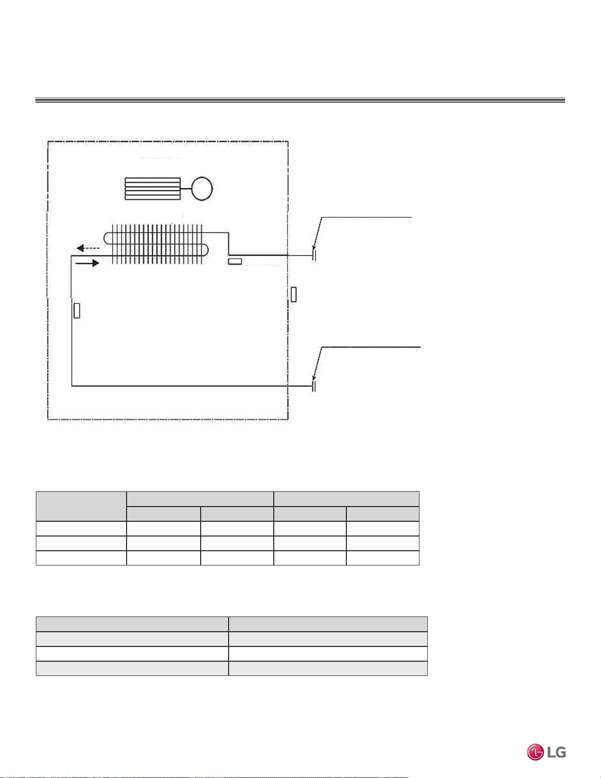
Refrigerant Flow Diagram
Figure 249: Four-way Vertical-Horizontal Air Handling Indoor Unit Refrigerant Flow Diagram.
FOUR-WAY VAHU INDOOR UNITS
Table 106: Four-way Vertical-Horizontal Air Handling Indoor Unit Refrigerant Pipe Sizes and Connection Sizes.
Model No.
Piping Size Connection Port Size
Liquid (inch) Vapor (inch) Liquid (inch) Vapor (inch)
LVN181HV4 1/4 1/2 3/8 5/8
LVN241HV4 1/4 1/2 3/8 5/8
LVN361HV4 3/8 5/8 3/8 5/8
Table 107: Four-way Vertical-Horizontal Air-Handling Indoor Unit Thermistor Details.
Description (Based on Cooling Mode) PCB Connector
Indoor Air Temperature Thermistor CN-ROOM
Evaporator Inlet Temperature Thermistor CN-PIPE/IN
Evaporator Outlet Temperature Thermistor CN-PIPE/OUT
Scirocco Fan
Heat Exchanger
Heating
Ev. Temperature Thermistor
Evaporator Outlet
Temperature
Thermistor
Cooling
M
Vapor Pipe Connection Port
(Flare Connection)
Indoor Air Temperature
Thermistor
Liquid Pipe Connection Port
(Flare Connection)
Due to our policy of continuous product innovation, some specications may change without notication.
©LG Electronics U.S.A., Inc., Englewood Cliffs, NJ. All rights reserved. “LG” is a registered trademark of LG Corp.
192 | VERTICAL-HORIZONTAL
Multi F and Multi F MAX Indoor Unit Engineering Manual
MULTI
F
MAX
MULTI
F
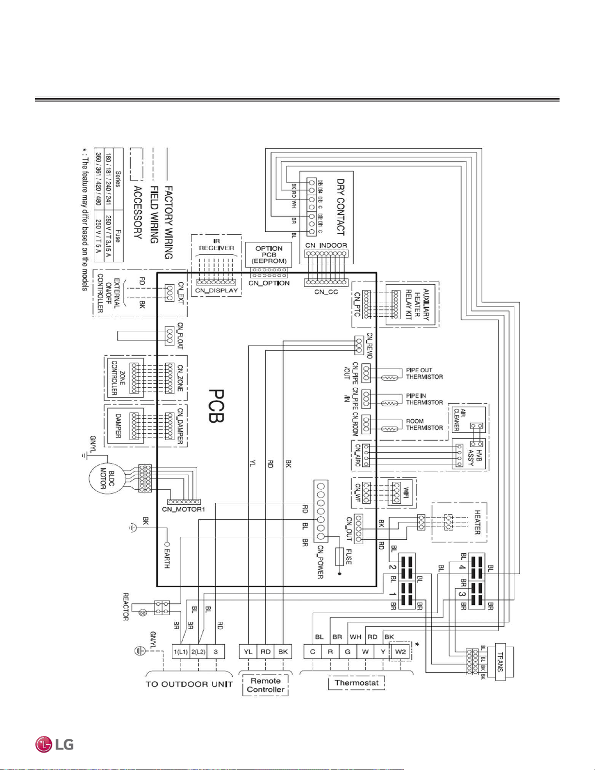
Wiring Diagram
FOUR-WAY VAHU INDOOR UNITS
Figure 250: Four-way Vertical-Horizontal Air-Handling Indoor Unit Wiring Diagram.
VERTICAL-HORIZONTAL | 193
Vertical-Horizontal Air Handling Unit
Due to our policy of continuous product innovation, some specications may change without notication.
©LG Electronics U.S.A., Inc., Englewood Cliffs, NJ. All rights reserved. “LG” is a registered trademark of LG Corp.
MULTI
F
MAX
MULTI
F
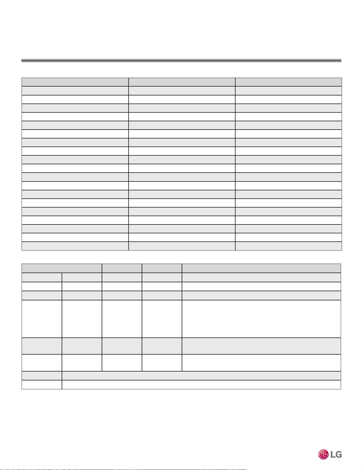
Connection Name Location Function
CN-POWER AC power supply AC Power line
CN-MOTOR1 Fan motor output Motor output of BLDC
CN_OUT Heater Connection for heater
CN-D/PUMP Drain pump output AC output for drain pump
CN-FLOAT Float switch input Float switch sensing
CN-ZONE Zone controller Zone controller connection
CN-OPTION Optional PCB EPROM Option PCB connection
CN-EXT External ON / OFF controller External ON / OFF controller connection
CN-DISPLAY Display Display of indoor status
CN-CC Dry contact Dry Contact connection
CN-PIPE/OUT (RD) Discharge pipe sensor Pipe out thermistor
CN-LEAK (VI) Refrigerant leak detector Refrigerant leak detector connection
CN-PIPE/IN (WH) Suction pipe sensor Pipe in thermistor
CN-REMO (GN) Wired remote controller Wired remote control connection
CN-ROOM (YL) Room sensor Room air thermistor
CN-DAMPER Damper Controller Damper connection
CN-AIRC Air Cleaner Air Cleaner connection
CN-WF Wifi Wifi Module connection
CN-PTC Auxiliary Heater Auxiliary Heater
Table 108: Wiring Diagram Connections.
Table 109: DIP Switch Settings.
DIP Switch Settings OFF ON Description
SW1 Communication Off (default) — —
SW2 CYCLE Off (default) — —
SW3 GROUP Master Slave Group control setting using wired remote controller.
SW4
DRY
CONTACT
Variable Auto
Dry contact mode setting.
1. Variable: Auto/manual mode can be chosen using the wide wired
remote controller or wireless remote controller (factory setting is
the manual mode).
2. Auto: For dry contact, it is always auto mode.
SW5 EXTRA1 Off On
• ON: Fan operates continuously.
• OFF: Default (Fan does not operate continuously).
SW6 HEATER Off On
• ON: Automatic heater operation.
• OFF: Default (manual heater operation).
SW7 Off
SW8 Off
To operate the indoor unit without Internal Electric Heater , Dip switch 1, 2, 6, 8 must be set OFF .
To operate the indoor unit with Internal Electric heater , Dip switch 6 must be set ON.
• SW6 ON: Automatic Heater operation: Heater operates automatically.
• SW6 OFF: Manual Heater operation: Owner ’s involvement is required for on/off operation.
If you operate the indoor unit with Internal Electric heater with Dip switch 5, note the following:
• SW5 ON: Fan operates continuously. During defrosting or oil return operation, uninterrupted heating can be attained, as a result of
continuous heater and fan operation.
• SW5 OFF: Fan discontinuous operation. There would be a reduction in heating capacity while defrosting or oil return operation.
Wiring Diagram
FOUR-WAY VAHU INDOOR UNITS
Due to our policy of continuous product innovation, some specications may change without notication.
©LG Electronics U.S.A., Inc., Englewood Cliffs, NJ. All rights reserved. “LG” is a registered trademark of LG Corp.
194 | VERTICAL-HORIZONTAL
Multi F and Multi F MAX Indoor Unit Engineering Manual
MULTI
F
MAX
MULTI
F
FOUR-WAY VAHU INDOOR UNITS
Factory Supplied Parts and Materials
Factory Supplied Materials
• Owner’s Manual
• Installation Manual
Required Tools
• Level
• Screwdriver
• Electric drill
• Hole core drill
• Flaring tool set
• Torque wrenches
• Hexagonal wrench
• Gas-leak detector
• Thermometer
Selecting the Best Location
Do’s
• Place the unit where air circulation through the ducts will not be
blocked.
• Place the unit where drainage can be obtained easily.
• Place the unit where noise prevention is taken into consideration.
• Ensure there is sufficient strength to bear the load of the indoor
unit.
• Ensure there is sufficient maintenance space.
• Locate the indoor unit in a location that is level, and where it can
be easily connected to the outdoor unit / branch distribution unit.
Installing in an Area Exposed to Unconditioned Air
In some installation applications, areas (floors, walls) in some rooms will be exposed to unconditioned air (room will be above or next to an
unheated garage or storeroom). To countermeasure:
• Verify that carpet is or will be installed (carpet will increase the temperature by three degrees).
• Add insulation between the floor joists.
• Install radiant heat or another type of heating system to the floor.
Installing in an Area with High Humidity Levels
If the environment is prone to humidity levels of 80% or more (near the ocean, lakes, etc.) or where steam could collect in the plenum:
• Install additional insulation to the indoor unit (glass wool insulation >13/32 inches thick).
• Install additional insulation to the refrigerant piping (insulation >13/16 inches thick).
• Seal all gaps between the indoor unit and the ceiling tiles (make the area air tight) so that humidity does not transfer from the plenum to the
conditioned space. Also, add a ceiling grille for ventilation.
WARNING
Installation work must be performed by trained personnel and in accordance with national wiring standards and all local or other applicable codes.
Improper installation can result in re, electric shock, physical injury, or death.
Note:
Read all instructions before installing this product. Become familiar with the unit’s components and connections, and the order of installation. Incorrect
installation can degrade or prevent proper operation.
Don’ts
• Do not install the unit near a heat or steam source, or where
considerable amounts of oil, iron powder, or flour are used.
• Do not install the unit where sulfuric acid and flammable or cor-
rosive gases are generated, vented into, or stored.
• Do not install the unit near high-frequency generators.
• Do not install the unit near a doorway.
The unit will be damaged, will malfunction, and/or will not op-
erate as designed if installed in any of the conditions listed.
• Indoor units (IDUs) must not be placed in an environment where the IDUs will be exposed to harmful volatile organic compounds
(VOCs) or in environments where there is improper air make up or supply or inadequate ventilation. If there are concerns about VOCs in
the environment where the IDUs are installed, proper air make up or supply and/or adequate ventilation must be provided. Additionally, in
buildings where IDUs will be exposed to VOCs, consider a third party factory-applied epoxy coating to the fan coils for each IDU where the
entire coil is dipped, not sprayed.
• If the unit is installed near a body of water, the installation parts are at risk of corroding. Appropriate anti-corrosion methods must be taken
for the unit and all installation parts.
VERTICAL-HORIZONTAL | 195
Vertical-Horizontal Air Handling Unit
Due to our policy of continuous product innovation, some specications may change without notication.
©LG Electronics U.S.A., Inc., Englewood Cliffs, NJ. All rights reserved. “LG” is a registered trademark of LG Corp.
MULTI
F
MAX
MULTI
F
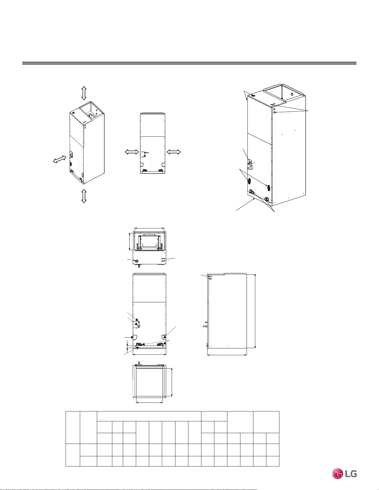
FOUR-WAY VAHU INDOOR UNITS
Installation and Best Layout Practices
Figure 251:Clearance Requirements.
Figure 252:General and Duct Connection Dimensions.
Figure 253:Location of Access Holes and Piping Connections.
Top
Front
Bottom
Side-right
Refrigerant
connections
Drain connections
for horizontal left
application
Drain
connections
for upflow
application
Air filter cover
Unit: inch
ODU
VAHU
Capacity
(kBtu/h)
Dimensions
Wiring
Knock out
Refrigerant
Pipe size
A B C
D E F G H
I J
Height Width Depth Power
Comm-
unication
Liquid Gas
Multi
Zone
18
24
48-11/16 18 21-1/4 1-9/16 17-1/2 20 17 12-1/8 1-11/16 7/8
36
48-11/16 18 21-1/4 1-9/16 17-1/2 20 17 12-1/8 1-11/16 7/8 3/8 5/8
G
J
C
J
B
I
E
F
D
A
H
Drain connections
for horizontal right
application
1/4 1/2
Refrigerant
Connections
Pipe
Liquid Gas
3/8 5/8
3/8 5/8
More than 23-5/8
clearance from
access panels
for Service
0 (zero) 0 (zero)
Unit : inch
More than
13-25/32
More than
13-25/32
Refrigerant Piping
Connections
Drain Connections
for Horizontal Install
Filter Access
Drain Connections
for Vertical Install
Access Holes
for Conduit
Access Holes
for Conduit
Due to our policy of continuous product innovation, some specications may change without notication.
©LG Electronics U.S.A., Inc., Englewood Cliffs, NJ. All rights reserved. “LG” is a registered trademark of LG Corp.
196 | VERTICAL-HORIZONTAL
Multi F and Multi F MAX Indoor Unit Engineering Manual
MULTI
F
MAX
MULTI
F
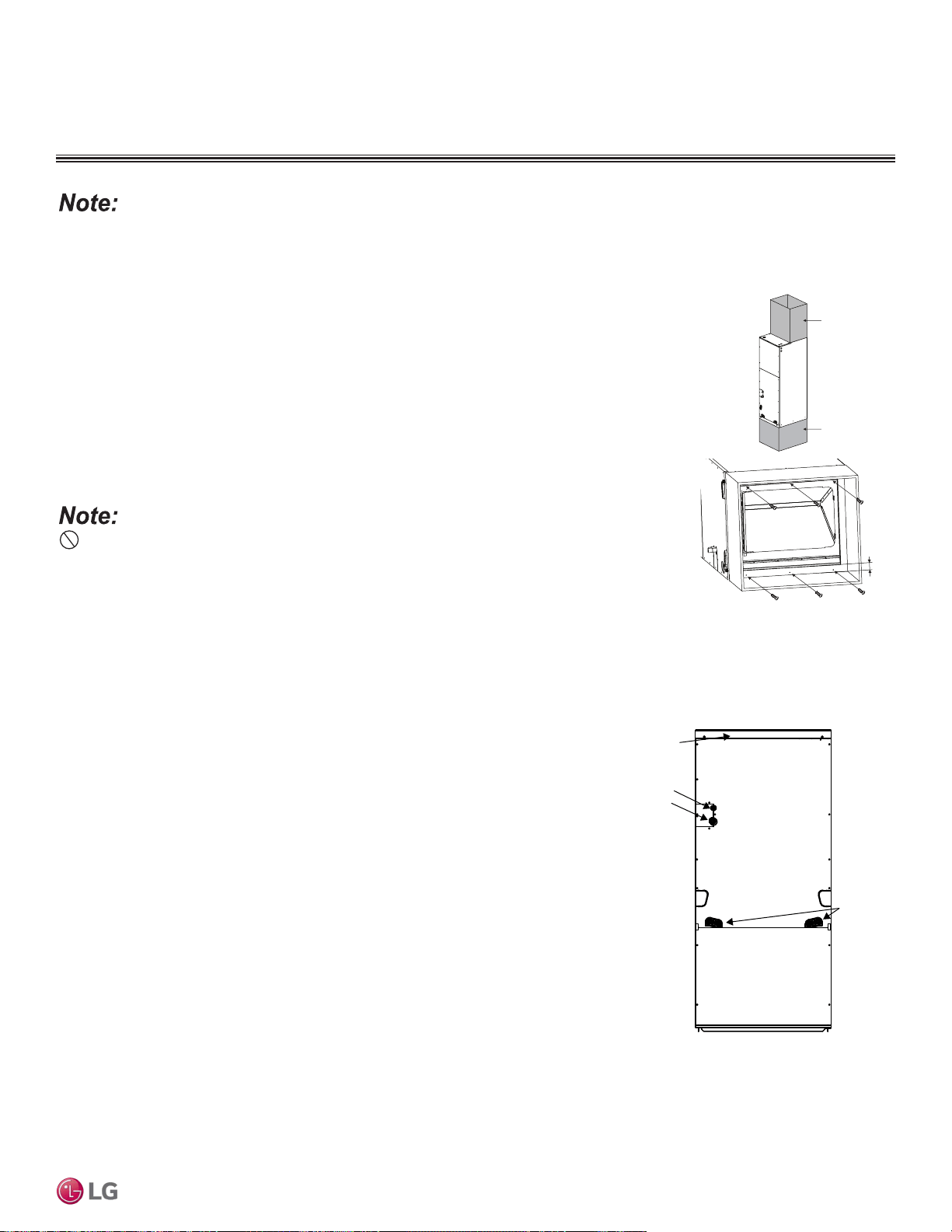
Vertical-Horizontal Air Handling Units can be installed in a choice of vertical upow, vertical downow (with optional downow kit), or horizontal (left
or right side) congurations.
Vertical (Upflow) Installation
• Unit must be positioned properly for plenum / duct installation.
• To maintain proper air flow, minimum height clearance is 14 inches.
• Plenum must be strong and secure enough to support the installation of adapter collars to accommo-
date duct work.
• Air handler platform must be sturdy enough to support the frame, plus any accessories (e.g., filter box).
• To prevent air leaks, seal all duct work according to local codes, but make sure that filter access is still
unobstructed.
• Vibration isolators (field supplied) must be installed between the unit frame and the platform. If neces-
sary, provide the installing contractor with an illustration of where the vibration isolator must be added
and how it must be positioned.
Do not install the screws on the front and back of the unit; doing so will block lter installation.
Use > 6 Screws (M4*25L)
Field Supplied
Return Air Duct /
Plenum
>1 inch
Field Supplied
Supply Air Duct
Figure 254:Vertical Installation /
Attaching the Bottom Duct.
FOUR-WAY VAHU INDOOR UNITS
Installation and Best Layout Practices
Vertical (Downflow) Installation
The Vertical-Horizontal Air Handling Unit can be field-converted to vertical downflow operation. The
optional vertical downflow kit is required. Downflow kit PNDFJ0 is required for 18-36MBH NJ chassis
units. The coil must be removed and repositioned in the chassis with the brackets of the downflow kit.
For installation details, refer to the instructions included with the kit.
Figure 255: Chassis after Downow
Field Conversion.
Refrigerant
connections
Drain
connections
for downflow
application
Air filter cover
VERTICAL-HORIZONTAL | 197
Vertical-Horizontal Air Handling Unit
Due to our policy of continuous product innovation, some specications may change without notication.
©LG Electronics U.S.A., Inc., Englewood Cliffs, NJ. All rights reserved. “LG” is a registered trademark of LG Corp.
MULTI
F
MAX
MULTI
F
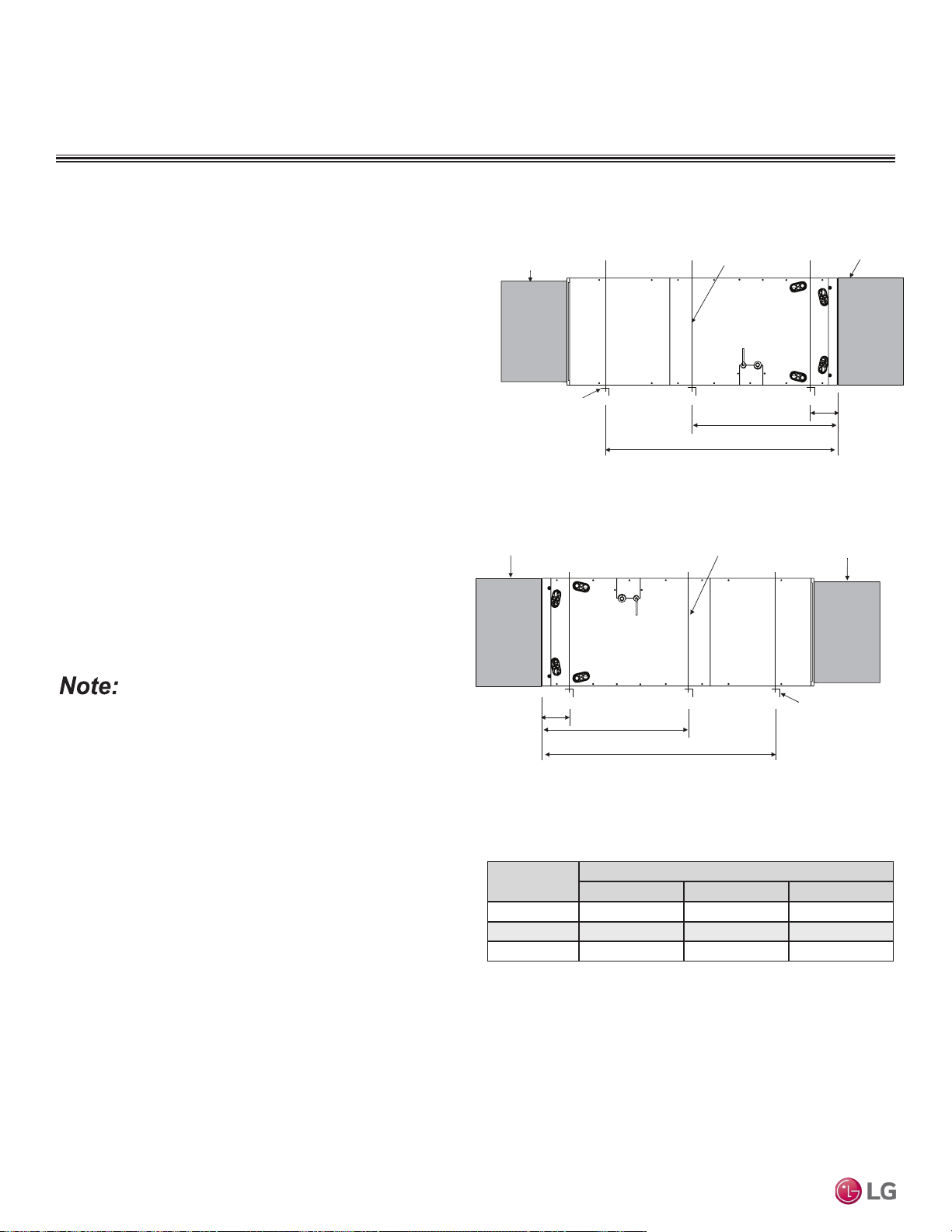
Horizontal Installation
• Units will be installed in horizontal left or horizontal right con-
figuration. Horizontal left is the factory default configuration. For
horizontal right, the unit must be field converted. The horizontal
right conversion requires removing the internal drain pan from the
left side of the unit and reinstalling on the right side. No conver-
sion kit is required. Refer to the installation manual for details.
• Units must be installed so that the access panels face to the side,
not facing up or down.
• Installation must be in accordance with all relevant building
codes, which will necessitate the installation of an external con-
densate pan (position the unit in or above the external conden-
sate pan).
• If the units are going to be suspended, use angled steel support
brackets with threaded rods to provide support from the bottom.
The brackets / threaded rods must be comparatively bigger /
longer than the unit, and each must be centered on the part of
the frame it supports.
• If the unit will not be suspended, use angled steel support
brackets, but also add vibration isolators (field supplied) to avoid
sound transmission. If necessary, provide the installing contractor
with an illustration of where the vibration isolator must be added
and how it must be positioned.
• Unit must be positioned properly for plenum / duct installation.
• Plenum must be strong and secure enough to support the instal-
lation of adapter collars to accommodate duct work.
To ensure proper drainage for horizontal installations, unit must be
installed within ±1/8 inches level of the unit’s length and width.
Capacity
(Btu/h)
Dimensions (inches)
A B C
18,000 4 23 41-11/32
24,000 4 23 41-11/32
36,000 4 23 41-11/32
Figure 256: Typical Horizontal Left Installation.
Table 110: Bracket / Bolt Position Dimensions for Horizontal Left and
Horizontal Right Installation.
B
A
C
>1-1/2 inch x 1-1/2 inch Angle
Recommended length >26 inches
with a 2-inch clearance on both
sides of the unit
>3/8 inch Threaded Rod
Field-Supplied
Supply Air Duct
Field Supplied
Return Air Duct / Plenum
Suspension Bolt Locations
FOUR-WAY VAHU INDOOR UNITS
Installation and Best Layout Practices
>1-1/2 inch x 1-1/2 inch Angle
Recommended length >26 inches
with a 2-inch clearance on both
sides of the unit
Suspension Bolt Locations
A
B
C
>3/8 inch Threaded Rod
Field Supplied
Return Air Duct / Plenum
Field-Supplied
Supply Air Duct
Figure 257: Typical Horizontal Right Installation.
Due to our policy of continuous product innovation, some specications may change without notication.
©LG Electronics U.S.A., Inc., Englewood Cliffs, NJ. All rights reserved. “LG” is a registered trademark of LG Corp.
198 | VERTICAL-HORIZONTAL
Multi F and Multi F MAX Indoor Unit Engineering Manual
MULTI
F
MAX
MULTI
F
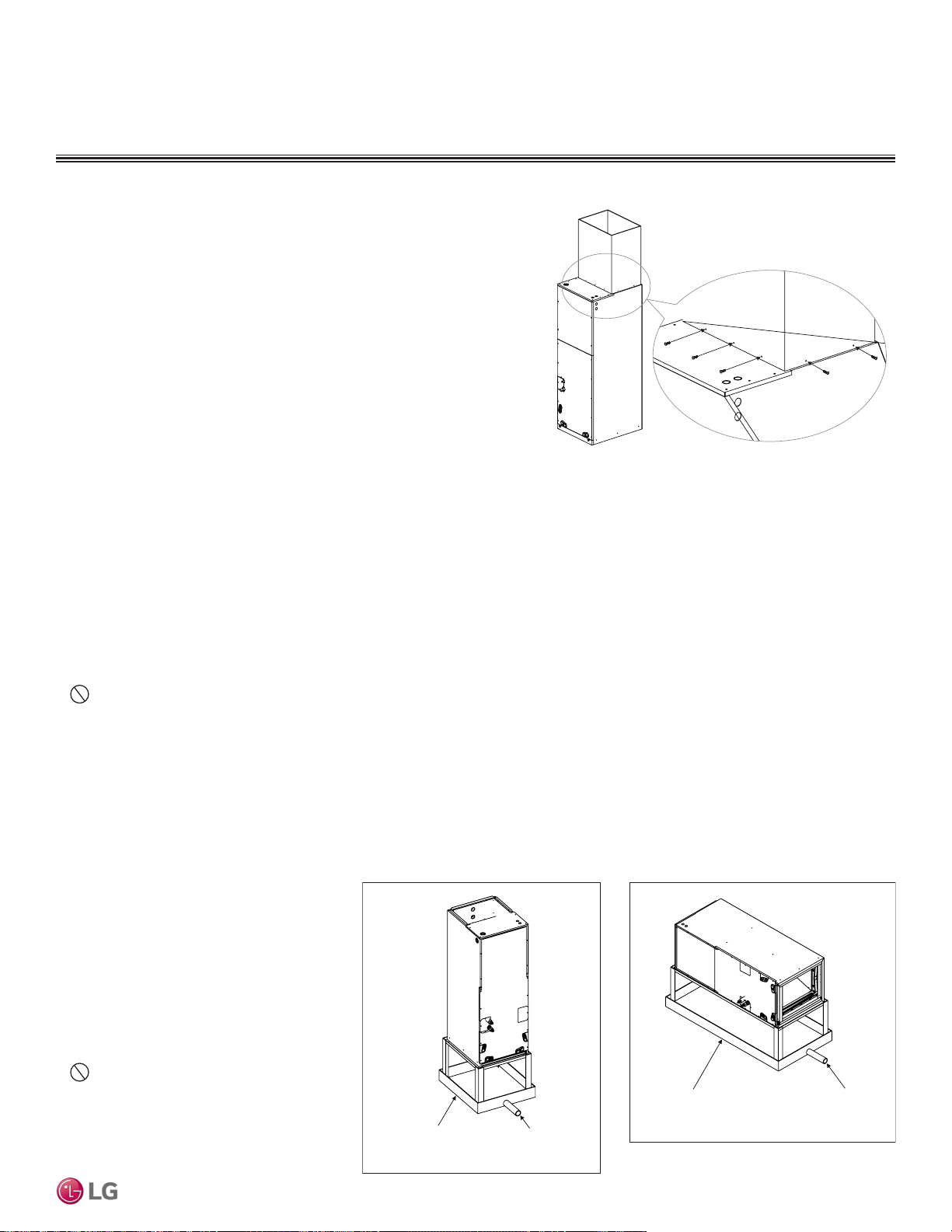
Installing the Ducts
• Use more than ten (10) screws to securely attach the supply ducts to the
unit. To prevent air leaks, seal around the duct opening before the duct is
secure.
• To prevent vibration transmission, install flexible connectors between ducts
and the unit. The flexible connectors must be made of a heat-resistant
material at the discharge connection if an electric heater is installed.
• Duct work must be insulated and covered with vapor barrier when routed
through unconditioned spaces. Include enough insulation to prevent
condensate from forming on the ducts.
• It will be necessary to add internal acoustical insulation lining for a metal
duct system if it does not include a 90° elbow and ten (10) feet between the
main duct and the first branch.
• Fibrous glass ducts could be used as a substitute if built and installed in accordance with the most recent edition of the Sheet Metal and
Air-Conditioning Contractors’ National Associate (SMACNA) standard.
• Also, fibrous duct work and acoustical insulation lining must also follow National Fire Protection Standard 90A or B as tested by UL
Standard 181 for Class 1 air ducts.
FOUR-WAY VAHU INDOOR UNITS
Installation and Best Layout Practices
>10 Screws
(M4*25L)
Figure 258:Securing the Ducts to the Unit.
Installing the Drain System
General Specifications
• To prevent property damage, optimize drain system performance by installing both a primary and secondary drain line, and properly size
the condensate traps.
• The primary and secondary drain line must be trapped to allow proper drainage of condensate water. If the secondary drain line is not used,
it must be capped.
• Do not block the filter access panel when installing the condensate drain piping. Prime the primary and secondary condensate traps
after running both to the drain pan.
• If the unit is installed above an inhabited space, add a field-supplied external condensate pan that runs underneath the entire frame (to
prevent damage from overflow). The additional external condensate line must run from the unit to the external condensate pan.
• Drain all generated condensate from the external condensate pan to an appropriate area. Install a trap in the condensate lines as near to
the indoor unit coil as possible.
• For horizontal right operation, the drain pan must be removed from the interior left side of the unit and reinstalled on the right side.
• All condensate must be drained from the exter-
nal condensate pan to some noticeable area.
• To prevent overflow, the outlet of each trap
must be positioned below its connection to the
condensate pan.
• All traps must be primed, insulated, and leak
tested if located above an inhabited space.
• Use a 3/4-inch PVC male pipe thread fitting at
the condensate pan connection. Tighten gently.
• Point the drain hose down for easier flow.
•
Do not just use the pipe joint or PVC /
CPVC piping on the indoor unit drain line con-
nections. Use only Teflon tape.
• Design the drain system to plan for winter
operation (condensate line will freeze up if con-
densate does not properly drain away).
Figure 259: Typical Vertical Up/Down
Installation Drain System.
Figure 260: Typical Horizontal Left/Right
Installation Drain System.
Field-Supplied
Drain Pan
Drain Piping
Field-Supplied
Drain Pan
Drain Piping
VERTICAL-HORIZONTAL | 199
Vertical-Horizontal Air Handling Unit
Due to our policy of continuous product innovation, some specications may change without notication.
©LG Electronics U.S.A., Inc., Englewood Cliffs, NJ. All rights reserved. “LG” is a registered trademark of LG Corp.
MULTI
F
MAX
MULTI
F

FOUR-WAY VAHU INDOOR UNITS
Installation and Best Layout Practices
Drain Piping Specifications
• Drain piping must have downward gradient of at
least 1/50 to 1/100; to prevent reverse flow, slope
must not be straight up and down.
• Do not damage the drain port on the indoor unit
when connecting the field-supplied drain piping.
Drain Hole
Gaps Should Not Be Present
Unit
Drain Piping
(Field Supplied)
Drain Piping Insulation
(Field Supplied)
U-Trap
B
C
A
3/4-inch Connecto
r
Field-Installed U-Trap Specifications
Figure 261:Close up of Drain Piping Connection.
Figure 262:Installing the U-Trap.
To prevent leaks cause by a block in the intake air lter, install a U-Trap.
A ≥ 2-9/16 inches
B ≥ 2C
C ≥ 2 x SP
SP = External Pressure in. WG
Example:
External Pressure= 0.4 in WG
A ≥ 2-9/16 inches
B ≥ 1-7/12 inches
C ≥ 19/24 inches
Drain Access Hole
Air Filter Cover
Main Drain with Suitable Trap. (Field-Supplied
Trap with Sufficient Depth Can Be Used.
Standard Size P-Traps Cannot Be Used.
Supplementary Drain with a
Proper Trap (Field Supplied Kit
Can Be Used)
Figure 263: Vertical Primary and
Secondary Drain Layout.
Figure 264: Horizontal Primary and
Secondary Drain Layout.
Refrigerant Piping Insulation
Field-installed vapor and liquid refrigerant piping lines must
be properly and completely covered in insulation (up to the
indoor unit piping connections) and must comply with federal,
state, and local requirements. Any exposed piping will gener-
ate condensate or will cause burns if touched. Insulation for
this field-installed refrigerant piping must have a minimum heat
resistance of 248°F.
If the indoor unit is installed and is operated at an extended
period in a highly humid environment (dew point tempera-
ture >73°F), however, condensate will form. To prevent this
phenomenon, install adiabatic glass wool insulation with a
thickness of 7/16 to 13/16 inches thick. Also, install glass wool
insulation on all indoor units that are located in the ceiling
plenum.
Drain Piping Insulation
Drain piping insulation must be 7/32 inches thick, minimum.
Insulating the Refrigerant and
Drain Piping
Connection for Liquid Piping
Refrigerant Piping
Insulation (Field Supplied)
Connection for Vapor Piping
Insulation Zip Tie (Field Supplied)
Refrigerant Piping Insulation (Field
Supplied)
Figure 265:Close Up of Refrigerant Piping Connection Insulation.
Gaps Should Not be Present
Overlap Piping Insulation
Refrigerant Piping Insulation (Field Supplied)
Insulation Clip (Field Supplied)
Refrigerant Piping Insulation
(Field Supplied)
Figure 266: Insulating the Refrigerant Piping and Refrigerant Piping
Connections.
Ensure all piping is insulated. Exposed piping can cause
burns if touched.
Due to our policy of continuous product innovation, some specications may change without notication.
©LG Electronics U.S.A., Inc., Englewood Cliffs, NJ. All rights reserved. “LG” is a registered trademark of LG Corp.
200 | VERTICAL-HORIZONTAL
Multi F and Multi F MAX Indoor Unit Engineering Manual
MULTI
F
MAX
MULTI
F

FOUR-WAY VAHU INDOOR UNITS
Installation and Best Layout Practices
Power Wiring / Communications Cable Guidelines
• Follow manufacturer’s circuit diagrams in the technical manuals.
• Confirm power source specifications.
• Confirm that the electrical capacity is sufficient.
• Starting current must be maintained ±10 percent of the rated current marked on the outdoor unit name plate.
• Confirm cable thickness specifications.
• It is required that a circuit breaker is installed, especially if conditions could become wet or moist.
• Include a disconnect in the power wiring system, add an air gap contact separation of at least 1/8 inch in each active (phase) conductor.
Access Holes
for Wiring
Control
Box Cover
Top Front
Panel
Connection Cable
Communications Cable
Nut
Conduit
Mounting Plate
1/2-inch Conduit
Connecting the Power Wiring and Communications Cable
1. To access the terminal block, first unscrew the top front panel,
and then unscrew the cover from the control box.
2. Knockout the access holes for the wiring. Insert the power wiring/
communications cable from the outdoor unit or branch distribution
unit (Multi F MAX systems only) through the conduits, pass the
conduits through the designated access holes, and then insert
the conduits into the control box. To prevent electromagnetic
interference and product malfunction, leave a space between the
power wiring and communications cable outside of the indoor
unit.
3. Connect the power wiring and communications cables to the
appropriate terminals on the indoor unit control board. Verify that
the color and terminal numbers from the outdoor unit or branch
distribution unit (Multi F MAX systems only) wiring match the
color and terminal numbers on the indoor unit.
4. Fill in any gaps around the conduit access holes with sealant to
prevent foreign particles from entering the indoor unit.
Figure 267:Connecting the Power Wiring and Communications Cable.
Indoor Unit Terminal Block
1(L1 )2(L2)
GND
3
Outdoor Unit Terminal Block or
Branch Distribution Unit Terminal Block
(Multi F MAX Systems Only)
GND
GRN /
YLW
BR
BL
RD
3 or S
Figure 268:Indoor Unit to Outdoor Unit / Branch Distribution Unit (Multi F MAX
systems only) Power Wiring / Communications Cable Connections.
• Loose wiring will cause unit to malfunction, overheat, and catch fire, resulting in severe injury or death.
Note:
• Terminal screws will become loose during transport. Properly tighten the terminal connections during installation.
A voltage drop will cause the following problems:
• Magnetic switch vibration, fuse breaks, or disturbance to the normal function of an overload protection device.
• Compressor will not receive the proper starting current.
VERTICAL-HORIZONTAL | 201
Vertical-Horizontal Air Handling Unit
Due to our policy of continuous product innovation, some specications may change without notication.
©LG Electronics U.S.A., Inc., Englewood Cliffs, NJ. All rights reserved. “LG” is a registered trademark of LG Corp.
MULTI
F
MAX
MULTI
F
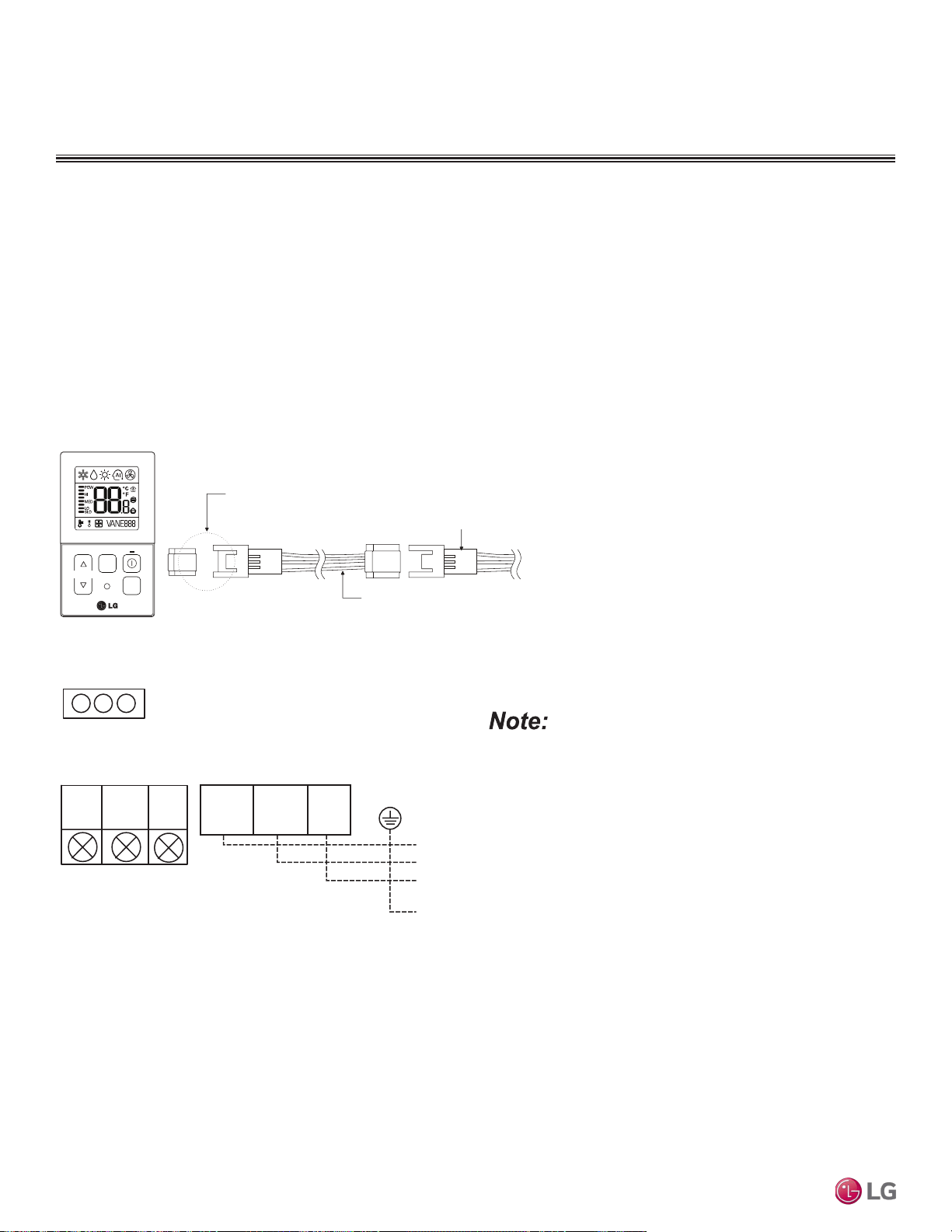
FOUR-WAY VAHU INDOOR UNITS
Installation and Best Layout Practices
Indoor Unit Terminal Block
1(L1 )2(L2)
GND
3
Branch Distribution Unit
GRN /
YLW
BR
BL
RD
CN-REMO
YL
RD BK
Comm.
12V
Power
Ground
Figure 269:PZCWRC1 LG Wired Remote Extension Cable.
Controller Options
Vertical-Horizontal Air Handling indoor units can be used with many LG-supplied wired controllers (sold separately). The wireless handheld
controller (Model No. PQWRHQ0FDB) is also an optional accessory with use of the wired controller.
Verify the connectors are properly inserted.
C/BOX Cable (Plug type)
Extension cable
To Indoor Unit
CN-REMO
Terminal
TEMP
FAN
SPEED
OPER
MODE
Figure 270:Wired Controller Connection on the Indoor Unit Terminal Block.
When using eld-supplied controller cable, make sure to connect
the yellow to yellow (communications wire), red to red (12V power
wire), and black to black (ground wire) terminals from the remote
controller to the indoor unit terminal blocks.
Wired Controller Connections
Controllers can connect to the indoor unit in one of two different ways.
1. LG Wired Remote Extension Cable with Molex plug (PZCWRC1; sold separately) that connects to the CN-REMO terminal on the indoor
unit PCB.
2. Field-supplied controller cable that connects to the indoor unit terminal block (must be at least UL2547 or UL1007, 22 AWG, two-core,
one-shield core, at least FT-6 rated if local electric and building codes require plenum cable usage).
Due to our policy of continuous product innovation, some specications may change without notication.
©LG Electronics U.S.A., Inc., Englewood Cliffs, NJ. All rights reserved. “LG” is a registered trademark of LG Corp.
202 | VERTICAL-HORIZONTAL
Multi F and Multi F MAX Indoor Unit Engineering Manual
MULTI
F
MAX
MULTI
F
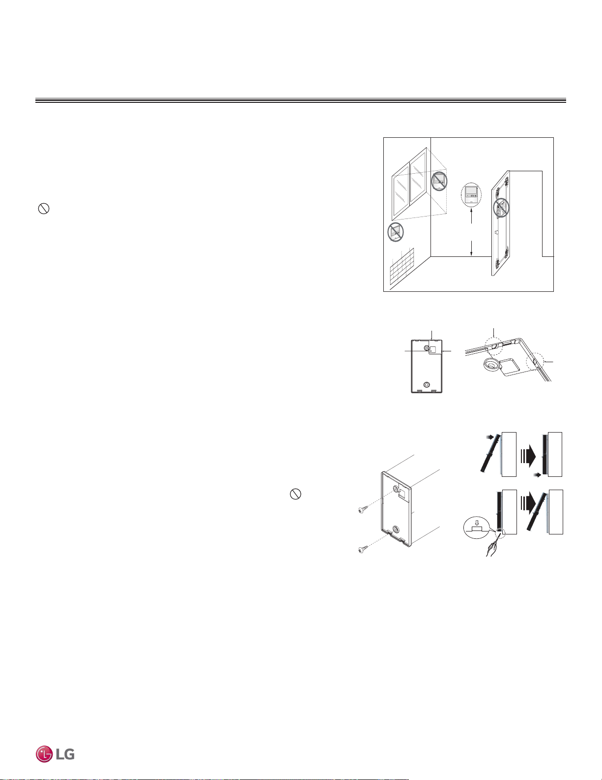
Figure 271:Proper Location for the Wired Controller.
4 to 5 feet
above the floor
NO
NO
NO
YES
Remote Controller
TEMP
Remote Controller
TEMP
Re
m
ot
e Co
nt
rol
l
er
TEMP
Wired controllers include a sensor to detect room temperature. To maintain
comfort levels in the conditioned space, the wired controller must be installed in
a location away from direct sunlight, high humidity, and where it could be directly
exposed to cold air. Controller must be installed four (4) to five (5) feet above the
floor where its LED display can be read easily, in an area with good air circula-
tion, and where it can detect an average room temperature.
Do not install the wired controller near or in:
• Drafts or dead spots behind doors and in corners
• Hot or cold air from ducts
• Radiant heat from the sun or appliances
• Concealed pipes and chimneys
• An area where temperatures are uncontrolled, such as an outside wall
Wired Controller Placement
Assigning the Thermistor for Temperature Detection
Each indoor unit includes a return air thermistor assigned to sense the temperature. If a wired controller is installed, there is a choice of
sensing temperature with either the indoor unit return air thermistor or the thermistor in the wired controller. It is also an option to set both
thermistors to sense temperature so that indoor unit bases its operation on the first thermistor to reach the designated temperature differen-
tial. For applicable indoor units, an optional Remote Temperature Sensor can be used in lieu of the return air thermistor—either alone or in
conjunction with a wired controller thermistor as previously described.
Hanging the Wired Controller
1. These steps are typical. Refer to the installation instructions with your control-
ler. The controller wiring / cable can be installed in one of three directions: top,
back, or on the right side. If top or right side installation is desired, remove
cable guide grooves on the controller, and then position wiring / cable on ap-
plicable side.
2. Choose and mark the area of installation, and then screw the wall plate into
place (using the provided parts). Install the controller wall plate to fit the elec-
trical box if one is present. Ensure that no gaps exist between the wall plate
and the wall itself.
3. Arrange wiring / cables so as not to interfere with the controller circuitry.
Position the wired controller on the wall plate. Snap into place by pressing the
bottom part of the wired controller onto the wall plate. Make sure that no gaps
exist between the wired controller and the wall plate on all sides.
4. To remove wired controller from the wall plate, insert a screwdriver into the
two holes at the bottom. Twist screwdriver to release controller. Do not
damage the controller components when removing.
Back
To p
To p
Right
Side
Right
Side
Wall Wall
Wall Wall
Installing the Controller
Removing the Controller
Figure 272:Removing the Cable Guide Grooves.
Figure 273:Attaching the
Wall Plate.
Figure 274:Installing /
Removing the Controller.
FOUR-WAY VAHU INDOOR UNITS
Installation and Best Layout Practices
VERTICAL-HORIZONTAL | 203
Vertical-Horizontal Air Handling Unit
Due to our policy of continuous product innovation, some specications may change without notication.
©LG Electronics U.S.A., Inc., Englewood Cliffs, NJ. All rights reserved. “LG” is a registered trademark of LG Corp.
MULTI
F
MAX
MULTI
F

Due to our policy of continuous product innovation, some specications may change without notication.
©LG Electronics U.S.A., Inc., Englewood Cliffs, NJ. All rights reserved. “LG” is a registered trademark of LG Corp.
204 | VERTICAL-HORIZONTAL
Multi F and Multi F MAX Indoor Unit Engineering Manual
MULTI
F
MAX
MULTI
F

“Equipment Selection Procedure” on page 206
“Placement Considerations” on page 213
APPLICATION
GUIDELINES
EQUIPMENT SELECTION PROCEDURE
Select the Equipment
Determine the Number of Zones
Multi F and Multi F with LG RED heat pump systems can cool or heat, but not simultaneously. When designing larger-capacity Multi F heat
pump systems or a Multi F MAX system, the designer will be able to combine spaces with similar load profiles located near or adjacent to
each other into “thermal zones.” After combining like spaces into zones that will be served by a single (or grouped) indoor unit(s), calculate
the peak cooling and heating loads for each zone.
Choosing the Appropriate Indoor Units
Determine the appropriate indoor unit capacity that satisfies the given zone load calculations, and choose how many (and which styles of)
indoor units will be required. See the table on the next page for allowable indoor unit to outdoor unit connections, and the maximum number
of connectable indoor units on each Multi F and Multi F MAX outdoor unit. When choosing indoor units, also consider the cooling and heating
CFM, featured airflow specifications, and static pressure (if applicable) for each indoor unit.
Avoid oversizing indoor units in an attempt to increase the air exchange rate in the space. Multi F and Multi F MAX systems are designed
for minimum airflow over the coil to maximize latent capacity while cooling, maintain a comfortable, consistent discharge air temperature
while heating, and minimize fan motor power consumption. In extreme cases, oversizing the indoor units will affect outdoor unit size selec-
tion and compromise the outdoor unit’s ability to effectively match the space load(s).
For proper system operation:
1. At least two indoor units must be connected to the outdoor unit.
2. Total connected indoor unit nominal capacity must be a minimum 40% and a maximum of 133% of outdoor unit nominal capacity.
3. To calculate the connected total indoor unit nominal capacity, simply sum up the nominal capacities of all indoor units.
• For high static duct and vertical-horizontal air handling indoor units, a 1.3 multiplier must first be applied before adding to the sum of
other indoor units (when connected to an ODU other than the LMU600HV).
• When high static duct and / or vertical-horizontal air handling indoor units are the only connected indoor units, the multiplier is 1.2.
To choose the multi-zone system that is the most appropriate for the space, as with traditional air-conditioning systems, follow similar
protocols outlined in Manual J from the Air Conditioning Contractors of America (ACCA; see www.acca.org).
1. Obtain the design conditions, and calculate the maximum cool and heat loads for the structure.
2. Select the equipment (choosing the appropriate indoor units and outdoor unit):
• Determine number of zones.
• Determine total number of indoor units (refer to zone load calculations when choosing indoor units).
• Determine number of indoor units allocated to each outdoor unit, considering allowable indoor unit connections, both indoor unit and
outdoor unit capacities, and system piping capabilities.
3. Determine the corrected capacity for the indoor units and outdoor unit using LATS HVAC software (preferred method) or:
• System Combination Tables.
• Capacity Tables (it will be necessary to interpolate).
• Capacity Coefficient Factors (such as refrigerant line length derates, design condition derates, defrost operation derate [heating mode],
altitude derate [if applicable]).
4. Compare corrected capacities to load calculations.
5. Reselect equipment if necessary.
Obtain Design Conditions, Calculate Maximum Cool / Heat Loads
Obtain the winter outdoor / indoor temperature and summer and winter outdoor / indoor temperature design parameters for the location in
which the system is installed. Determine if summer or winter design gains, relative humidity, and building features like skylights, orientation,
number of occupants, etc., would change the total heat loss / gain and sensible / latent heat gain, and then calculate the maximum cool and
heat loads for the space (using Manual J or energy modeling programs).
For allocated capacity information, see the combination tables in the "Multi F / Multi F MAX Combination Data Manual" on www.lghvac.com.
For performance data, see "Multi F / Multi F MAX Performance Data Manual" on www.lghvac.com. Also refer to the appropriate manuals on
www.lghvac.com for combination and capacity data for Multi F with LG RED / Multi F MAX with LG RED units.
Due to our policy of continuous product innovation, some specications may change without notication.
©LG Electronics U.S.A., Inc., Englewood Cliffs, NJ. All rights reserved. “LG” is a registered trademark of LG Corp.
206 | APPLICATION GUIDELINES
Multi F and Multi F MAX Indoor Unit Engineering Manual
MULTI
F
MAX
MULTI
F
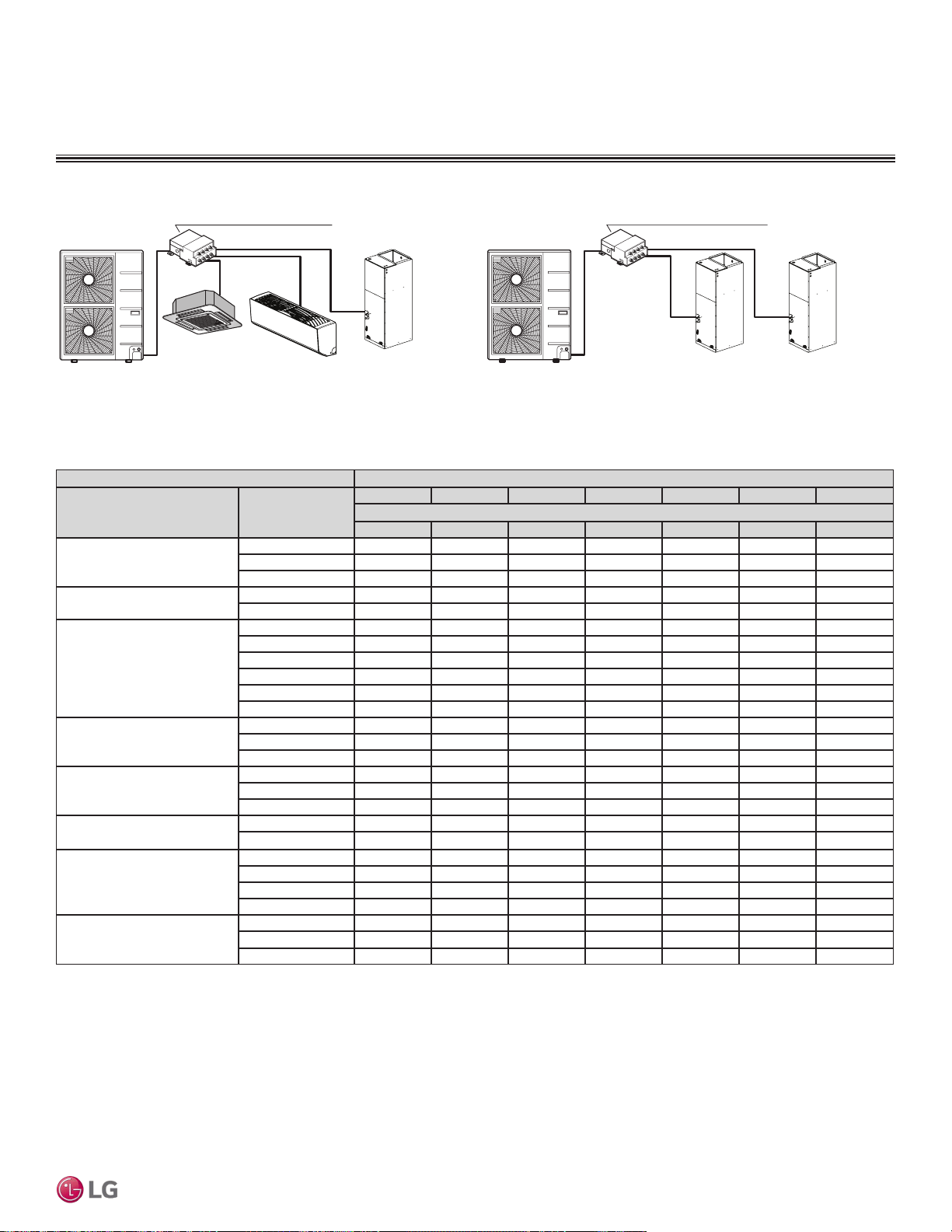
EQUIPMENT SELECTION PROCEDURE
Table 111: Allowable Indoor Unit to Multi F / Multi F MAX with LGRED Outdoor Unit Connections.
Branch Distribution Unit (PMBD3620)
+
24 x 1.2 24 x 1.2 + Total Capacity Index = = 57.6 < 73
Branch Distribution Unit (PMBD3641)
First Indoor Unit:
LMCN125HV
+ + Outdoor Unit: LMU540HV
12 9 36 x 1.3 + + Total Capacity Index = = 67.8 < 73
Acceptable
Combination
Second Indoor Unit:
LSN090HSV4
Third Indoor Unit:
LVN360HV4
Outdoor Unit: LMU540HV
First Indoor Unit:
LVN240HV4
Second Indoor Unit:
LVN240HV4
Acceptable
Combination
Example 1
Example 2
Multiplier Examples
Indoor units Outdoor units
Model Type
Indoor Unit Nominal
Capacity (Btu/h)
LMU18CHV LMU24CHV LMU30CHV LMU36CHV LMU480HV LMU540HV LMU600HV
Maximum No. of Connectable Indoor Units
2 3 4 4 8 8 8
ART COOL Mirror
9,000 O O O O O O O
12,000 O O O O O O O
18,000 - O O O O O O
ART COOL Gallery
9,000 O O O O O O O
12,000 O O O O O O O
Standard Wall Mounted
7,000 O O O O O O O
9,000 O O O O O O O
12,000 O O O O O O O
15,000 O O O O O O O
18,000 - O O O O O O
24,000 - O O O O O O
Low Wall Console
9,000 O O O O O O O
12,000 O O O O O O O
15,000 O O O O O O O
Ceiling Concealed Duct-
Low Static
9,000 O O O O O O O
12,000 O O O O O O O
18,000 - O O O O O O
Ceiling Concealed Duct-
High Static
24,000 - - O O O O O
36,000 - - - - O O O
Four-Way Ceiling Cassette
7,000 O O O O O O O
9,000 O O O O O O O
12,000 O O O O O O O
18,000 - O O O O O O
Vertical-Horizontal Air Handler
18,000 - O O O O O O
24,000 - - O O O O O
36,000 - - - - O O O
Due to our policy of continuous product innovation, some specications may change without notication.
©LG Electronics U.S.A., Inc., Englewood Cliffs, NJ. All rights reserved. “LG” is a registered trademark of LG Corp.
APPLICATION GUIDELINES | 207
Application Guidelines
MULTI
F
MAX
MULTI
F
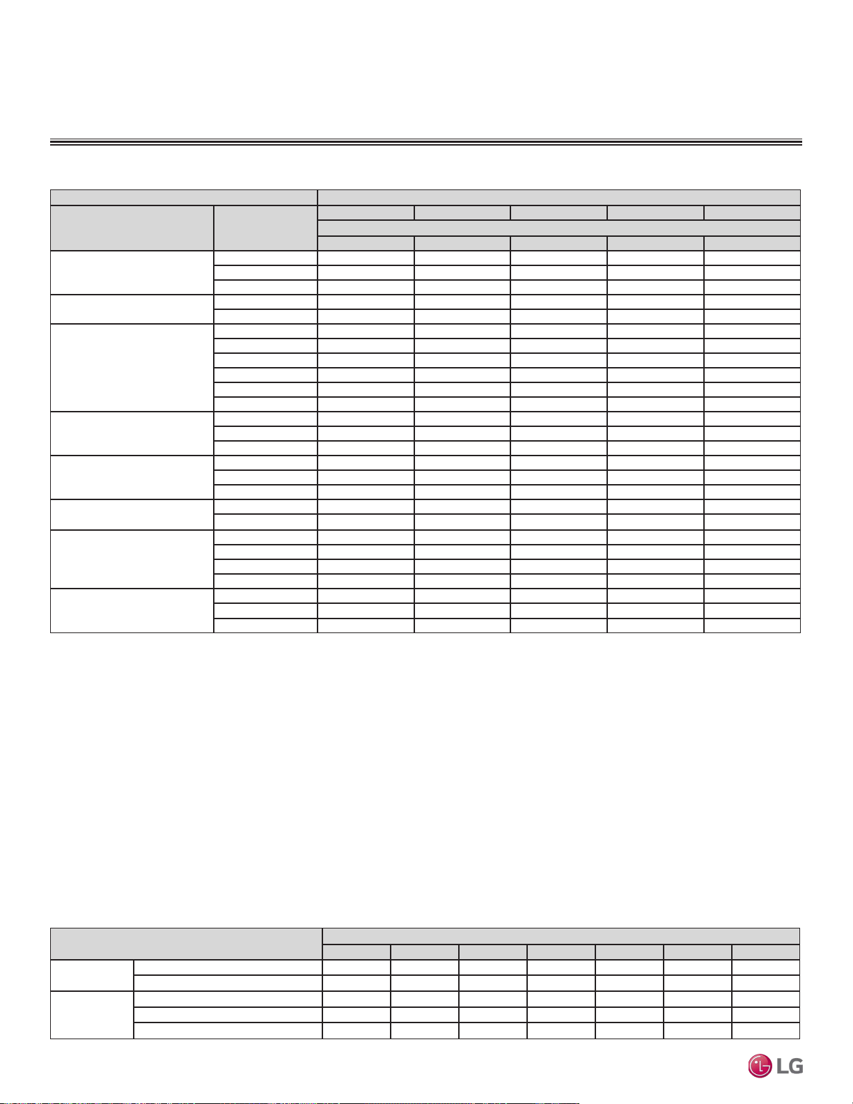
Table 112: Multi F / Multi F Max Rated Outdoor Unit Capacity.
Outdoor Units
LMU18CHV LMU24CHV LMU30CHV LMU36CHV LMU480HV LMU540HV LMU600HV
Rated Capacity
(Btu/h)*
Cooling 17,000 20,000 30,000 32,000 48,000 52,500 60,000
Heating 22,000 24,000 32,000 36,000 54,000 58,000 64,000
Connectable
Indoor
Units
Minimum No. of Connectable IDUs 2 2 2 2 2 2 2
Maximum No. of Connectable IDUs 2 3 4 4 8 8 8
Maximum Capacity Index 24,000 33,000 40,000 48,000 65,000 73,000 81,000
EQUIPMENT SELECTION PROCEDURE
Table 113: Allowable Indoor Unit to Multi F / Multi F MAX with LGRED Outdoor Unit Connections.
Choosing the Appropriate Outdoor Unit
After all indoor units are properly sized to offset the applicable loads in each zone, select the outdoor unit by choosing a size that meets both
the load-cooling requirement, and offsets the sum of the heating load. Then, the system’s combination ratio must be evaluated and confirmed
it is within the allowable range (the combination ratio compares the nominal capacity of all connected indoor units to the nominal capacity of
the outdoor unit serving them). The total nominal capacity of all indoor units must be smaller than the total nominal capacity of the outdoor
unit. If the combination ratio is more than 100%, the designer is undersizing the outdoor unit relative to the combined nominal capacity of the
connected indoor units. In some designs, oversized indoor units will be unavoidable in the case where the smallest size indoor unit available
from LG is larger than what is necessary to satisfy the zone load. This scenario will also occur when an indoor unit selection one size down
from the selected unit is slightly short of fulfilling the design load requirements, and the designer must choose the next largest size unit.
Sometimes it is required to choose a larger capacity outdoor unit if the installation space is big enough. Also, it will be prudent to oversize the
outdoor unit to address those times when the weather conditions will exceed the design conditions, to minimize the possibility of ventilation
systems that causes the space temperature to drift outside design parameters, or when the indoor unit’s entering air temperature falls outside
the approved design temperature range.
Indoor units Outdoor units
Model Type
Indoor Unit Nominal
Capacity (Btu/h)
LMU180HHV LMU240HHV LMU300HHV LMU360HHV LMU420HHV
Maximum No. of Connectable Indoor Units
2 3 4 5 6
ART COOL Mirror
9,000 O O O O O
12,000 O O O O O
18,000 - O O O O
ART COOL Gallery
9,000 O O O O O
12,000 O O O O O
Standard Wall Mounted
7,000 O O O O O
9,000 O O O O O
12,000 O O O O O
15,000 O O O O O
18,000 - O O O O
24,000 - O O O O
Low Wall Console
9,000 O O O O O
12,000 O O O O O
15,000 O O O O O
Ceiling Concealed Duct-
Low Static
9,000 O O O O O
12,000 O O O O O
18,000 - O O O O
Ceiling Concealed Duct-
High Static
24,000 - - O O O
36,000 - - - - O
Four-Way Ceiling Cassette
7,000 O O O O O
9,000 O O O O O
12,000 O O O O O
18,000 - O O O O
Vertical-Horizontal Air Handler
18,000 - O O O O
24,000 - - O O O
36,000 - - - - O
Due to our policy of continuous product innovation, some specications may change without notication.
©LG Electronics U.S.A., Inc., Englewood Cliffs, NJ. All rights reserved. “LG” is a registered trademark of LG Corp.
208 | APPLICATION GUIDELINES
Multi F and Multi F MAX Indoor Unit Engineering Manual
MULTI
F
MAX
MULTI
F
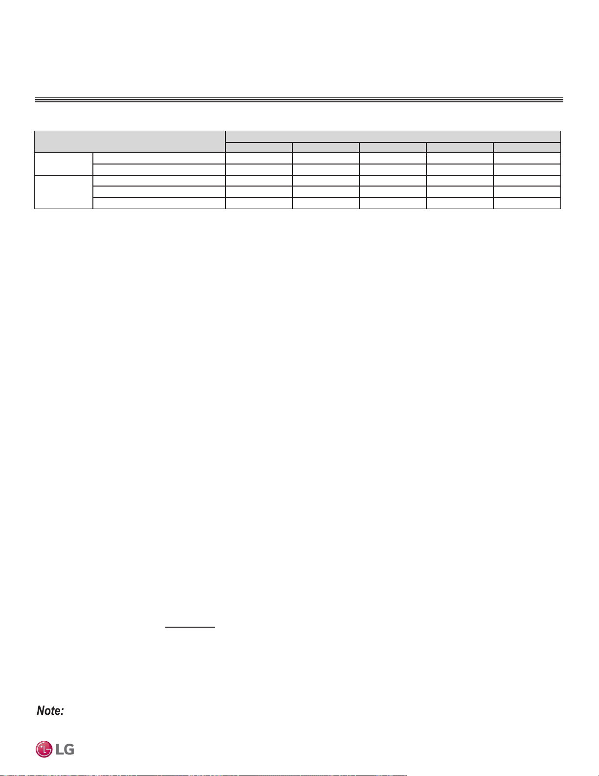
Determine the Corrected Capacity
The corrected cooling / heating capacity is different from the rated cooling / heating capacity. The corrected capacity includes changes in
unit performance after considering design temperatures, available capacity that can be allocated from the outdoor unit, pressure drop due
to refrigerant line length, defrost operation in heating mode, and (if applicable) altitude. Depending on the location of the building, additional
capacity correction factors will need to be applied.
Using the Outdoor Unit Cooling and Heating Capacity Tables
Rated cooling capacity ratings are obtained with air entering the indoor unit at 80ºF dry bulb (DB) and 67ºF wet bulb (WB), and outdoor ambi-
ent conditions of 95ºF dry bulb (DB) and 75ºF wet bulb (WB). Rated heating capacity ratings are obtained with air entering the indoor unit at
70ºF dry bulb (DB) and 60ºF wet bulb (WB) and outdoor ambient conditions of 47ºF dry bulb (DB) and 43ºF wet bulb (WB).
To evaluate the total outdoor unit capacity at design conditions perform a selection using LATS HVAC software (preferred method) or refer-
ence the Performance Data Capacity Tables. All design temperatures are not explicitly shown in the charts, therefore, interpolation will be
necessary to calculate the capacity for specific design conditions. Based on the premise that capacity follows a linear curve, the following
formula can be applied:
(y - y1) / (y2 - y1) = (x - x1) / (x2 - x1)
Where
y = Missing Capacity (Capacity at the Design Temperature).
1
y1 = Capacity at Lower Temperature (Smaller value of the two nearest published TC datapoints).
y2 = Capacity at Higher Temperature (Higher value of the two nearest published TC datapoints).
x = Design Temperature (Temperature not shown in published capacity tables).
2
x1 = (Smaller value of the two nearest published temperature datapoints).
x2 = (Larger value of the two nearest published temperature datapoints).
1
Median between two published Total Capacity [TC] Btu/h datapoints in the capacity table.
2
Median between two nearest published temperature datapoints.
EQUIPMENT SELECTION PROCEDURE
Using the Indoor Unit Cooling and Heating Capacity Tables
The datapoints shown in the indoor unit cooling and heating capacity charts are based on (and convey) an indoor unit operating with maxi-
mum possible refrigerant flow from the outdoor unit and before any derates are applied. In other words, the capacities displayed reflect what
the indoor unit would produce if it was the only indoor unit that required capacity, and the outdoor unit did not have to allocate any capacity to
another indoor unit.
System operation with a combination of indoor units is not conveyed in these charts, however, the information can be used to calculate
indoor unit allocated capacity (without using the system combination tables). Simply calculate by using the formula:
Where
Qidu(combi) = Qodu(rated) x Qidu(rated)
ΣQidu(rated)
• The formula can be used to find individual indoor unit capacity for Multi F MAX / Multi F MAX with LGRED systems.
• A more accurate method to determine expected capacity would be to apply the outdoor unit’s corrected capacity instead of rated capacity.
Qidu(combi) = Individual Indoor Unit Combination Capacity.
Qodu(rated) = Outdoor Unit Rated Capacity.
Qidu(rated) = Individual Indoor Unit Rated Capacity.
ΣQidu(rated) = Total Connected Indoor Unit Rated Capacity.
Table 114: Multi F / Multi F MAX with LGRED Rated Outdoor Unit Capacity.
Outdoor Units
LMU180HHV LMU240HHV LMU300HHV LMU360HHV LMU420HHV
Rated Capacity
(Btu/h)*
Cooling 18,000 24,000 28,400 36,000 42,000
Heating 22,000 26,000 28,600 41,000 45,000
Connectable
Indoor
Units
Minimum No. of Connectable IDUs 2 2 2 2 2
Maximum No. of Connectable IDUs 2 3 4 5 6
Maximum Capacity Index 24,000 33,000 40,000 48,000 56,000
Due to our policy of continuous product innovation, some specications may change without notication.
©LG Electronics U.S.A., Inc., Englewood Cliffs, NJ. All rights reserved. “LG” is a registered trademark of LG Corp.
APPLICATION GUIDELINES | 209
Application Guidelines
MULTI
F
MAX
MULTI
F
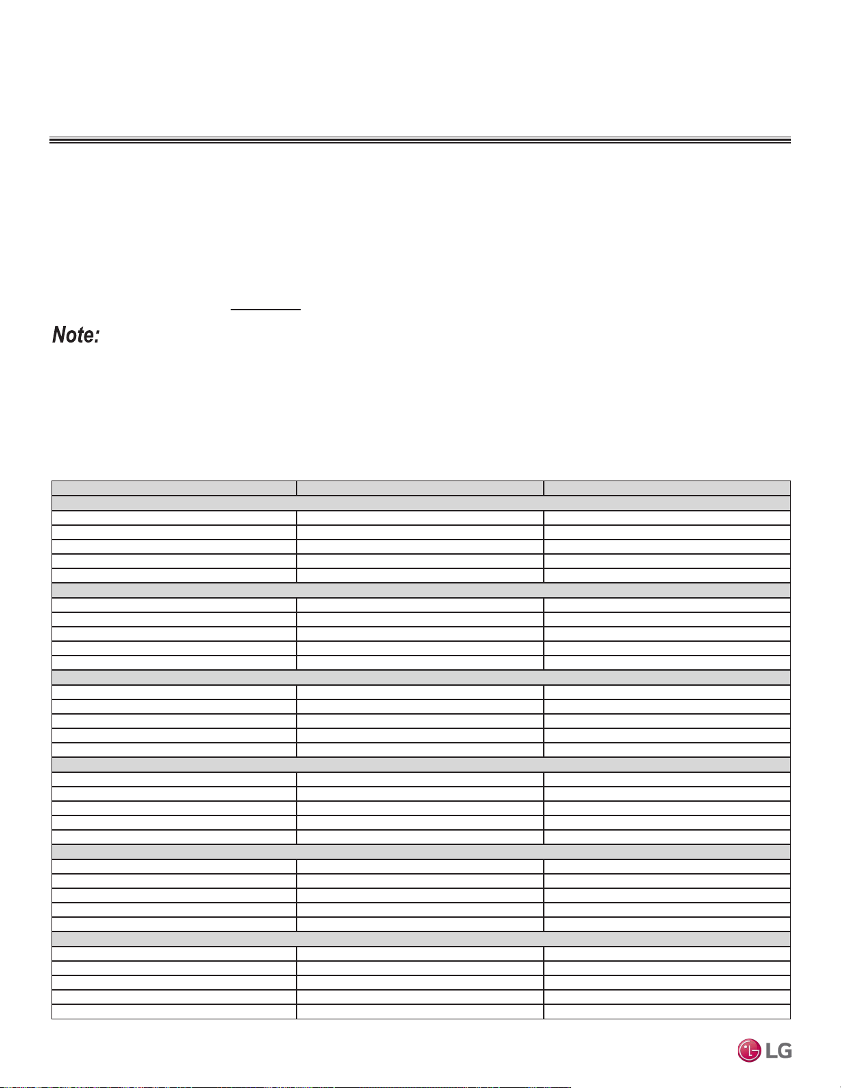
Qidu(combi) = Qodu(rated) x Qidu(rated)
ΣQidu(rated)
EQUIPMENT SELECTION PROCEDURE
Using the System Combination Tables
Multi F system combination tables illustrate how each indoor unit receives a percentage of total outdoor unit rated capacity. Allocation is
based on:
• Combinations of Non-Ducted Indoor Units
• Combinations of Ducted Indoor Units
• Combinations of Mixed Non-Ducted and Ducted Indoor Units
Multi F MAX system combination tables only show the total connected indoor unit capacity, but individual indoor unit capacity can be
calculated using the formula:
A more accurate method to determine expected capacity would be to apply the outdoor unit’s corrected capacity instead of rated capacity.
Table 115: Multi F / Multi F with LGRED Outdoor Unit (Multiple Piping) to Indoor Unit Refrigerant Line Length Derates.
Piping Length (feet) Cooling Capacity (%) Heating Capacity (%)
7,000 Btu/h Indoor Unit Models
25.0 100.0 100.0
32.8 98.4 99.2
49.2 95.8 97.8
65.6 93.2 96.4
82.0 90.6 95.0
9,000 Btu/h Indoor Unit Models
25.0 100.0 100.0
32.8 98.0 99.0
49.2 94.8 97.4
65.6 91.6 95.8
82.0 88.4 94.2
12,000 Btu/h Indoor Unit Models
25.0 100.0 100.0
32.8 97.6 98.6
49.2 93.8 96.4
65.6 89.9 94.1
82.0 86.1 91.9
15,000 Btu/h Indoor Unit Models
25.0 100.0 100.0
32.8 97.2 98.2
49.2 93.0 95.4
65.6 88.8 92.6
82.0 84.6 89.8
18,000 Btu/h Indoor Unit Models
25.0 100.0 100.0
32.8 98.6 99.6
49.2 96.4 99.0
65.6 94.1 98.3
82.0 91.9 97.7
24,000 Btu/h Indoor Unit Models
25.0 100.0 100.0
32.8 98.2 99.2
49.2 95.4 98.0
65.6 92.4 96.6
82.0 89.6 95.4
Capacity Coefficient Factors
Refrigerant Line Length Derates
For air-cooled systems, a capacity correction factor will have to be applied to account for the length of the system’s refrigerant pipe. Rate of
change in capacity due to increased piping lengths is shown in the tables below and on the next page.
Due to our policy of continuous product innovation, some specications may change without notication.
©LG Electronics U.S.A., Inc., Englewood Cliffs, NJ. All rights reserved. “LG” is a registered trademark of LG Corp.
210 | APPLICATION GUIDELINES
Multi F and Multi F MAX Indoor Unit Engineering Manual
MULTI
F
MAX
MULTI
F
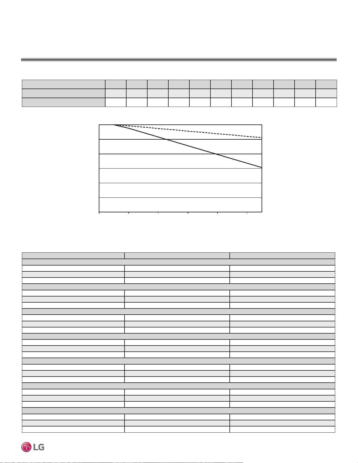
EQUIPMENT SELECTION PROCEDURE
Table 116: Multi F MAX / Multi F MAX with LGRED Outdoor Unit to Branch Distribution Unit Refrigerant Line Length Derates.
Main Piping Length (feet) 16.4 32.8 49.2 65.6 82.0 98.4 114.8 131.2 147.6 164.0 180.4
Cooling Capacity (%)
100.0 98.8 97.3 95.8 94.3 92.8 91.3 89.8 88.3 86.8 85.3
Heating Capacity (%)
100.0 99.6 99.2 98.7 98.3 97.8 97.4 96.9 96.5 96.0 95.6
0 32.8 65.6 98.4 131.2 164.0 180.4
Main piping length (ft.)
70.0
75.0
80.0
85.0
90.0
95.0
100.0
Capacity (%)
Heating
capacity
Cooling
capacity
Figure 275: Multi F MAX / Multi F MAX with LGRED Outdoor Unit to Branch Distribution Unit Refrigerant Line Length Derate Chart.
Table 117: Multi F MAX and Multi F MAX with LGRED Branch Distribution Unit to Indoor Unit Refrigerant Line Length Derates.
Piping Length (feet) Cooling Capacity (%) Heating Capacity (%)
7,000 Btu/h Indoor Unit Models
16.4 100.0 100.0
32.8 98.0 99.5
49.2 96.0 98.9
9,000 Btu/h Indoor Unit Models
16.4 100.0 100.0
32.8 97.5 98.8
49.2 95.0 97.5
12,000 Btu/h Indoor Unit Models
16.4 100.0 100.0
32.8 97.0 98.3
49.2 94.0 96.5
15,000 Btu/h Indoor Unit Models
16.4 100.0 100.0
32.8 97.2 98.2
49.2 93.0 95.4
18,000 Btu/h Indoor Unit Models
16.4 100.0 100.0
32.8 98.3 99.5
49.2 96.5 99.0
24,000 Btu/h Indoor Unit Models
16.4 100.0 100.0
32.8 97.8 99.2
49.2 95.5 98.4
36,000 Btu/h Indoor Unit Models
16.4 100.0 100.0
32.8 97.9 98.8
49.2 95.7 97.6
Due to our policy of continuous product innovation, some specications may change without notication.
©LG Electronics U.S.A., Inc., Englewood Cliffs, NJ. All rights reserved. “LG” is a registered trademark of LG Corp.
APPLICATION GUIDELINES | 211
Application Guidelines
MULTI
F
MAX
MULTI
F
EQUIPMENT SELECTION PROCEDURE
Altitude Correction Factor
The impact of air density must be considered on systems installed at a significant altitude above sea level, therefore, locally accepted
altitude correction factors must be applied.
Table 118: Outdoor Unit Frost Accumulation Factor (Heating)
1
.
There will be temporary reduction in capacity when frost / ice accumulates on the outside surface of the outdoor unit heat exchanger. The level
of capacity reduction depends on a number of factors, for example, outdoor temperature (°F DB), relative humidity (RH), and the amount of frost
present.
Entering DB (ºF)
19.4 23.0 26.6 32.0 37.4 41.0 44.6
Derate factor
0.98 0.95 0.93 0.86 0.93 0.96 1.0
1
At 85% outdoor air relative humidity.
The frost accumulation factor does not account for effects of snow accumulation restricting airflow
through the outdoor unit coil.
Defrost Correction Factor for Heating Operation
The outdoor unit heating capacity will need to be adjusted for frost accumulation on air-cooled systems. If design day conditions are below
the dewpoint of the surrounding air, frost will not be a problem and no correction factor is needed. In certain weather conditions, however,
frost will form and accumulate on the air-cooled outdoor unit coil and impact the coils ability to transfer heat. If significant frost accumulates
on the outdoor unit coil, a defrost algorithm will start automatically. The timing between defrost periods is determined by the system’s ability
to achieve a target head pressure value.
Capacity and AHRI ratings tables do not factor in capacity reduction when frost has accumulated on the condenser coil, nor during defrost
operation.
Integrated heating capacity values can be obtained using the formula:
A = B x C
Where:
A = Integrated Heating Capacity.
B = Value found in the Capacity Table.
C = Correction Factor for Frost Accumulation Factor (from Table 101).
Check the Indoor and Outdoor Unit Selection(s)
Compare the corrected cooling and heating capacities to the load calculations. Is each capacity sufficient for the zone it serves?
For each indoor unit, the corrected capacity must be at least equal to the total of the cooling design load (plus ventilation load, if applicable)
for the space(s) served by the indoor unit. For each indoor unit, the corrected capacity also must be at least equal to the total of the heating
design load (plus ventilation load, if applicable) for the space(s) and / or thermal zones served by the indoor unit.
The outdoor unit selected must be large enough to offset the total cooling load for all spaces it serves (account for ventilation air cooling load
if the ventilation air has not been pretreated to room neutral conditions). The outdoor unit must also be large enough to offset the total heat-
ing load for all spaces it serves.
If the corrected heating capacity ratio exceeds 100%, reselect the equipment, or change the system design by moving some of the load to
another system.
• Understand the design safety factors.
• Reference load calculations for actual cooling and heating capacities (applies in 99% of applications – consider total load when latent load
is greater than 30%).
• Verify that the sensible load of the zone is satisfied.
• Use caution when sizing to meet listed capacity specifications for the scheduled manufacturer’s equipment.
If further system design assistance is needed, or you have a unique application you would like to discuss, contact your LG sales rep.
1. Outdoor Unit Rated Capacity.
Q
odu(rated)
(From capacity tables).
2. Outdoor Unit Capacity at Ti, To Temperature.
Q
odu(Ti, To)
(From capacity tables).
3 Outdoor Unit Capacity Coefficient Factor.
F
(Ti, To)
= Q
odu(Ti, To)
/ Q
odu(rated)
4. Piping Correction Factor (From Capacity Coefficient
Factor Tables).
F
(length)
for each piping length
5. Individual Indoor Unit Combination Capacity.
Q
idu (combi)
= Q
odu(rated)
x Q
idu(rated)
/ Q
idu(rated-total)
6. Individual Indoor Unit Actual Capacity.
Q
idu (actual)
= Q
odu(combi)
x F
(Ti, To)
x F
(length, altitude)
System Sizing Check Formulas
Conclusions and Recommendations
Due to our policy of continuous product innovation, some specications may change without notication.
©LG Electronics U.S.A., Inc., Englewood Cliffs, NJ. All rights reserved. “LG” is a registered trademark of LG Corp.
212 | APPLICATION GUIDELINES
Multi F and Multi F MAX Indoor Unit Engineering Manual
MULTI
F
MAX
MULTI
F
PLACEMENT CONSIDERATIONS
Selecting the Best Location for the Indoor Units
Note:
Select a location for installing the indoor units that will meet the following conditions:
• Indoor Units (IDUs) must not be placed in an environment where the IDUs will be exposed to harmful volatile organic compounds (VOCs) or
in environments where there is improper air make up or supply or inadequate ventilation. If there are concerns about VOCs in the environ-
ment where the IDUs are installed, proper air make up or supply and/ or adequate ventilation must be provided. Additionally, in buildings
where IDUs will be exposed to VOCs consider a factory-applied epoxy coating to the fan coils for each IDU.
• Within allowable parameters for proper connection to the outdoor unit (or Branch Distribution unit, if a Multi F MAX system).
• So that condensation drainage can be conveniently routed away.
• Include enough space around the indoor unit so that it is accessible for maintenance and service purposes.
• Where electrical noise / electromagnetic waves will not affect indoor unit operation. Maintain proper distances between the indoor units and
electric wires, audio and visual appliances, breaker / circuit panels, etc. If the frequency signal of the appliance is unstable, then install the
indoor unit a minimum of ten (10) feet away, and run the power and transmission cables through a conduit.
• An area that is level and with enough strength to bear the weight of the indoor unit(s).
• No obstacles to air circulation around the unit; keep proper distances from ceilings, doorways, floor, walls, etc.
• An area where operation sound won’t disturb occupants.
• An area that does not expose the indoor unit(s) to heat, water, steam, oil splattering or spray.
Selecting the Best Location for the Outdoor Unit
When deciding on a location to place the outdoor unit, be sure to choose an area where run-off from defrost will not accumulate and freeze
on sidewalks or driveways which will create unsafe conditions.
CAUTION
DANGER
To avoid the possibility of re, do not install the unit in an area where combustible gas will generate, ow, stagnate, or leak. Failure to
do so will cause serious bodily injury or death.
Do not install the unit in a location where acidic solution and spray (sulfur) are often used as this will cause serious bodily injury or
death. Do not use the unit in environments where oil, steam, or sulfuric gas are present as this will cause serious bodily injury or death.
WARNING
Selecting the Best Location for the Branch Distribution (BD) Unit
Note:
Branch Distribution (BD) units are used only with Multi F MAX / Multi F MAX with LGRED systems to distribute the refrigerant from the out-
door unit to up to eight indoor units. Select location indoors that will meet the following conditions:
• Within allowable parameters for proper connection to the Multi F MAX / Multi F MAX with LGRED outdoor unit and indoor unit(s); refrigerant
piping and wire lengths must not exceed amounts specified by LG Electronics, U.S.A., Inc.
• Condensate drain piping is not required.
• Ensure there is enough space in the installation area for service purposes; install the refrigerant piping and electrical wiring system in an
easily accessible location.
• Level where there is enough strength to bear the weight of the BD unit.
•
Do not install the BD unit in a location where it would be subjected to strong radiation heat from heat sources.
• Avoid an installation environment where the BD unit would be exposed to heat, water, steam, oil splattering or spray.
• Install the unit in a location where any sound it generates will not disturb occupants in the surrounding rooms.
• No obstacles to air circulation around the unit; keep proper distances from ceilings, doorways, floor, walls, etc.
• Where high-frequency electrical noise / electromagnetic waves will not affect operation. Maintain proper distances between the BD unit(s)
and electric wires, audio and visual appliances, breaker / circuit panels, etc.
Select a location for installing the outdoor unit that will meet the following general conditions:
• A location strong enough to bear the weight of the outdoor unit.
• A location that allows for optimum air flow and is easily accessible for inspection, maintenance, and service.
Due to our policy of continuous product innovation, some specications may change without notication.
©LG Electronics U.S.A., Inc., Englewood Cliffs, NJ. All rights reserved. “LG” is a registered trademark of LG Corp.
APPLICATION GUIDELINES | 213
Application Guidelines
MULTI
F
MAX
MULTI
F
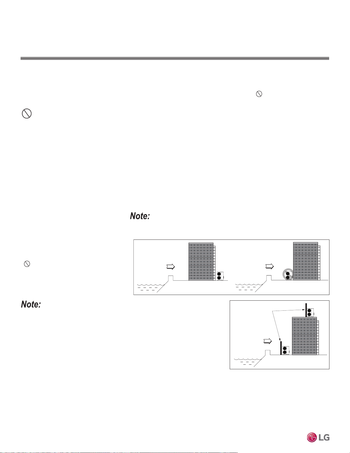
Rooftop Installations
If the outdoor unit is installed on a roof structure, be sure to level the unit. Ensure the roof structure and anchoring method are adequate for
the unit location. Consult local codes regarding rooftop mounting.
PLACEMENT CONSIDERATIONS
Selecting the Best Location for the Outdoor Unit, continued.
• Where it will not be subjected to direct thermal radiation from other heat sources, nor an area that would not expose the outdoor unit to
heat or steam like discharge from boiler stacks, chimneys, steam relief ports, other air conditioning units, kitchen vents, plumbing vents,
and other sources of extreme temperatures.
• Where high-frequency electrical noise / electromagnetic waves will not affect operation.
• Where operating sound from the unit will not disturb inhabitants of surrounding buildings.
• Where the unit will not be exposed to direct, strong winds.
Ocean winds
Ocean winds
Ocean winds
Windbreaker
Planning for Snow and Ice
In climates that experience snow buildup, place the unit on a raised platform to ensure proper condenser airflow. The raised support platform
must be high enough to allow the unit to remain above possible snow drifts. Mount the unit on a field-provided stand that is higher than the
maximum anticipated snowfall for the location. Design the mounting base to prevent snow accumulation on the platform in front or back of
the unit case. If necessary, provide a field fabricated hood to keep snow and ice and/or drifting snow from accumulating on the coil surfaces.
Use inlet and discharge duct or hoods to prevent snow or rain from accumulating on the fan inlet and outlet guards. Best practice prevents
snow from accumulating on top of the unit. Consider tie-down requirements in case of high winds or where required by local codes.
Oceanside Installation Precautions
• Install the outdoor unit on the side of the
building opposite from direct ocean winds.
• Select a location with good drainage.
• Periodically clean dust or salt particles off of
the heat exchanger with water.
•
Avoid installing the outdoor unit where it
would be directly exposed to ocean winds.
Additional anti-corrosion treatment will need
to be applied to the outdoor unit at oceanside
locations.
If the outdoor unit must be placed in a
location where it would be subjected to
direct ocean winds, install a concrete
windbreaker strong enough to block any
winds. Windbreaker height and width
must be more than 150% of the outdoor
unit, and be installed at least 27-1/2
inches away from the outdoor unit to
allow for airflow.
Ocean winds will cause corrosion, particularly on the condenser and evaporator ns, which,
in turn could cause product malfunction or inefcient performance.
• Where piping between the outdoor unit, indoor unit(s), and BD units (Multi F MAX systems only) are within allowable limits.
• Include space for drainage to ensure condensate flows properly out of the unit when it is in heating mode. Avoid placing the outdoor unit
in a low-lying area where water could accumulate.
Due to our policy of continuous product innovation, some specications may change without notication.
©LG Electronics U.S.A., Inc., Englewood Cliffs, NJ. All rights reserved. “LG” is a registered trademark of LG Corp.
214 | APPLICATION GUIDELINES
Multi F and Multi F MAX Indoor Unit Engineering Manual
MULTI
F
MAX
MULTI
F
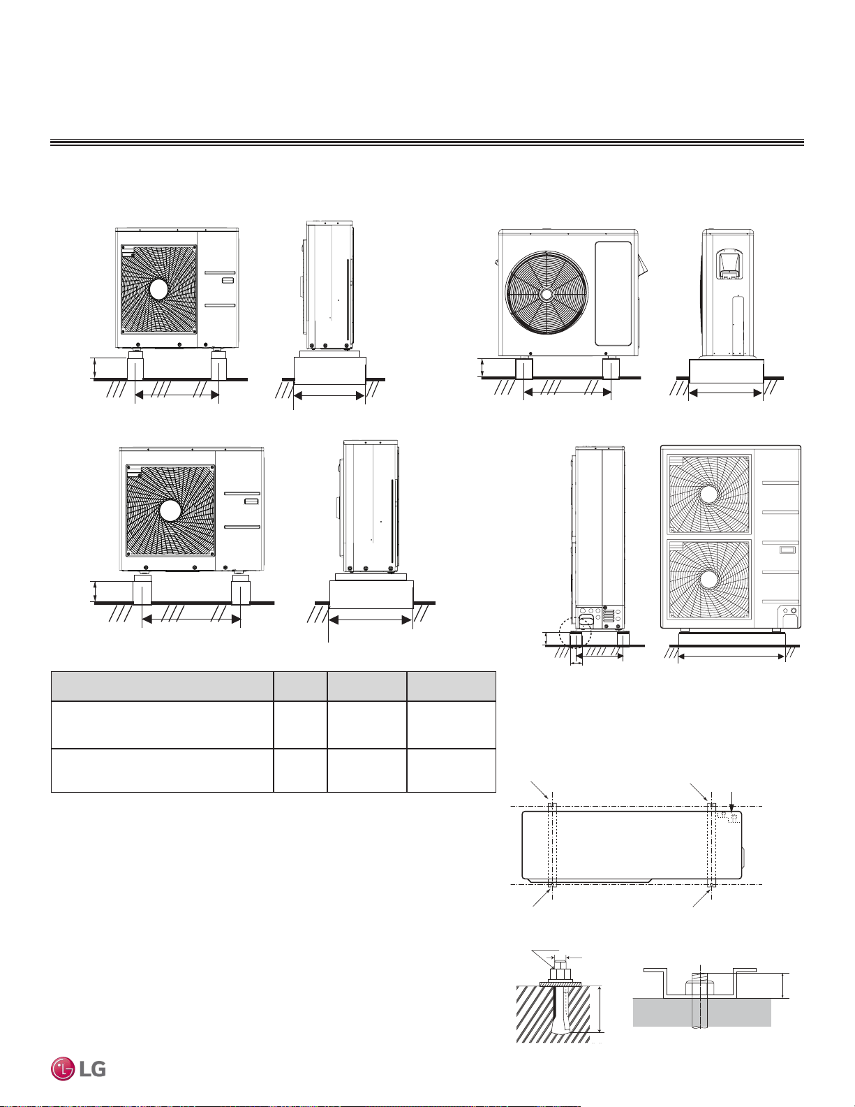
PLACEMENT CONSIDERATIONS
M10
Anchor Bolt
2-3/4~4 23/32
13/16
Unit: Inch
Bolt
Refrigerant Pipe
Connection Location
Top of Outdoor Unit
(Looking Down)
Bolt
Bolt
Bolt
Bolting the Outdoor Unit to the Platform
1. Ensure that the concrete platform will not degrade easily, and has enough
strength to bear the weight of the unit.
2. Include an H-beam support. Firmly attach the corners, otherwise the support will
bend.
3. Use a hexagon nut.
4. Use anti-vibration material.
5. Include enough space around the concrete foundation for condensate drainage.
6. Seal all wiring and piping access holes to prevent bugs from entering the unit.
Figure 276: Outdoor Unit Foundation Requirements.
Concrete Platform Specifications
• Concrete foundations must be made of one part cement, two parts sand, and four
parts gravel.
• The surface of the foundation must be finished with mortar with rounded edges,
and weatherproofed.
Figure 277: Bolting the Outdoor Unit to the Platform.
Table 119: Outdoor Unit Foundation Specications.
Outdoor Unit Platform Requirements
Minimum
3-15/16
21-1/2
Minimum 14-9/16
Unit: Inch
LMU18CHV and LMU24CHV Outdoor Units
Figure 278: Close up of Bolt Attachment.
Outdoor Unit Type Bolt Type
Concrete
Height
Bolt Depth
LMU180HHV, LMU240HHV, LMU300HHV,
LMU18CHV, LMU24CHV, LMU30CHV,
LMU36CHV
M10-J
Minimum Four
(4) Inches
Minimum Three
(3) Inches
LMU360HHV, LMU420HHV, LMU480HV,
LMU540HV,LMU600HV
M10-J
Minimum Eight
(8) Inches
Minimum Three
(3) Inches
LMU360HHV, LMU420HHV, LMU480HV, LMU540HV, LMU600HV
Outdoor Units
Minimum
3-15/16)
21-1/2
Minimum 14-9/16
Unit: Inch
LMU30CHV and LMU36CHV Outdoor Units
Minimum
8
7-7/8
15-3/4
Minimum 24-13/32
Unit: Inch
Minimum 4
24-13/32
Minimum 16
Unit: Inch
LMU180HHV, LMU240HHV, and LMU300HHV Outdoor Units
Due to our policy of continuous product innovation, some specications may change without notication.
©LG Electronics U.S.A., Inc., Englewood Cliffs, NJ. All rights reserved. “LG” is a registered trademark of LG Corp.
APPLICATION GUIDELINES | 215
Application Guidelines
MULTI
F
MAX
MULTI
F
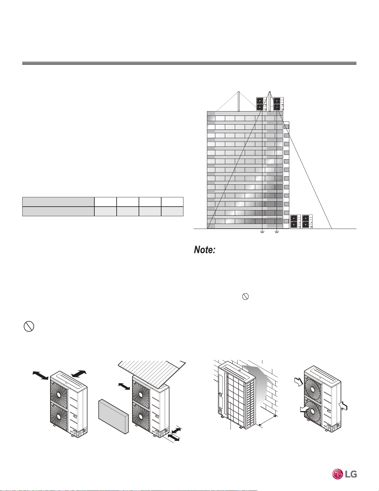
Tie-Downs and Lightening Protection
Tie-Downs
• The strength of the roof must be checked before installing the
outdoor units.
• If the installation site is prone to high winds or earthquakes, when
installing on the wall or roof, securely anchor the mounting base
using a field-provided tie-down configuration approved by a local
professional engineer.
• The overall tie-down configuration must be approved by a local
professional engineer. Always refer to local code when using a
wind restraint system.
Lightening Protection
• To protect the outdoor unit from lightning, it must be placed within
the specified lightning safety zone.
• Power cable and communication cable must be installed five (5)
feet away from lightning rod.
• A high-resistance ground system must be included to protect
against induced lightning or indirect strike.
Ground
Safe zone
Lightning rod
Protection Angle (25˚~55˚)
1.5m
1.5m
5 feet
Lightning rod
Figure 279: Lightening Protection Diagram.
Table 120: Safety Zone Specications.
Building Height (feet)
66 98 148 197
Protection Angle (˚)
55 45 35 25
If the building does not include lightning protection, the outdoor unit
will be damaged from a lightening strike. Inform the customer of this
possibility in advance.
Minimum 11-13/16
Air inlet grille
Blown
air
Strong
wind
Strong
wind
Minimum 11-13/16
Minimum 23-5/8
Sunroof
Fence or
obstacles
Minimum 11-13/16
Air inlet grille
Blown
air
Strong
wind
Strong
wind
Minimum 19-1/16
Fence or
obstacles
Unit: Inch
Minimum 11-13/16
Ensure that the space at the back of the outdoor unit is a minimum of 11-13/16 inches, and
include a minimum of 23-5/8 inches at the right side of the unit for service.
If the outdoor unit discharge side faces a wall, include a minimum of 19-11/16 inches
between the outdoor unit and the wall. Install the outdoor unit so that the discharge port is
set at a right angle to the wind direction.
When installing the outdoor unit, consider service, inlet, and outlet, and minimum allowable space requirements as illustrated in the following
diagrams.
PLACEMENT CONSIDERATIONS
Outdoor Unit Service Access and Allowable Clearances
Appropriate airflow through the outdoor unit coil is critical for proper unit operation.
• Include enough space for airflow and for service access. If installing multiple outdoor units, avoid placing the units where the discharge
of one unit will blow into the inlet side of an adjacent unit.
• If an awning is built over the unit to prevent direct sunlight or rain exposure, make sure that the discharge air of the outdoor unit isn’t restricted.
• No obstacles to air circulation around the unit; keep proper distances from ceilings, fences, floor, walls, etc. (Install a fence to prevent pests
from damaging the unit or unauthorized individuals from accessing it.)
Due to our policy of continuous product innovation, some specications may change without notication.
©LG Electronics U.S.A., Inc., Englewood Cliffs, NJ. All rights reserved. “LG” is a registered trademark of LG Corp.
216 | APPLICATION GUIDELINES
Multi F and Multi F MAX Indoor Unit Engineering Manual
MULTI
F
MAX
MULTI
F
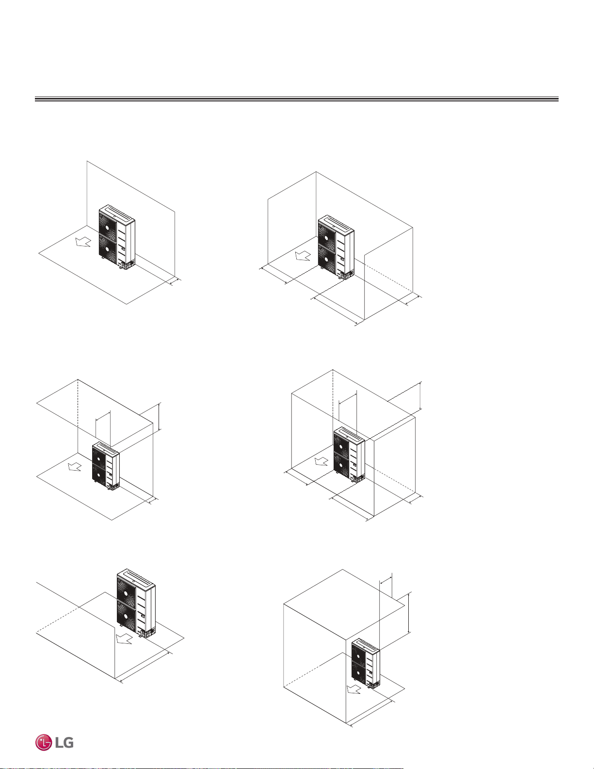
PLACEMENT CONSIDERATIONS
Clearance Requirements when Different Obstacles are Present (Unit: Inch).
Minimum 11-13/16"
Minimum 19-11/16"
Minimum 39-3/8"
Minimum 11-13/16"
Maximum 19-11/16"
Minimum 11-13/16"
Minimum 39-3/8"
Minimum 23-19/32"
Obstacles above and on the air intake side. Obstacles above, on the air intake side,
and on both left and right sides
Minimum 11-13/16"
Minimum 11-13/16"
Minimum 11-13/16"
Minimum 23-19/32"
Obstacle on the suction side only.
Obstacles on the suction side and
on both left and right sides.
Minimum 19-11/16"
Minimum 19-11/16"
Minimum 19-11/16"
Minimum 39-3/8"
Obstacle just on the
air discharge side.
Obstacles above and on the
air discharge side.
Due to our policy of continuous product innovation, some specications may change without notication.
©LG Electronics U.S.A., Inc., Englewood Cliffs, NJ. All rights reserved. “LG” is a registered trademark of LG Corp.
APPLICATION GUIDELINES | 217
Application Guidelines
MULTI
F
MAX
MULTI
F
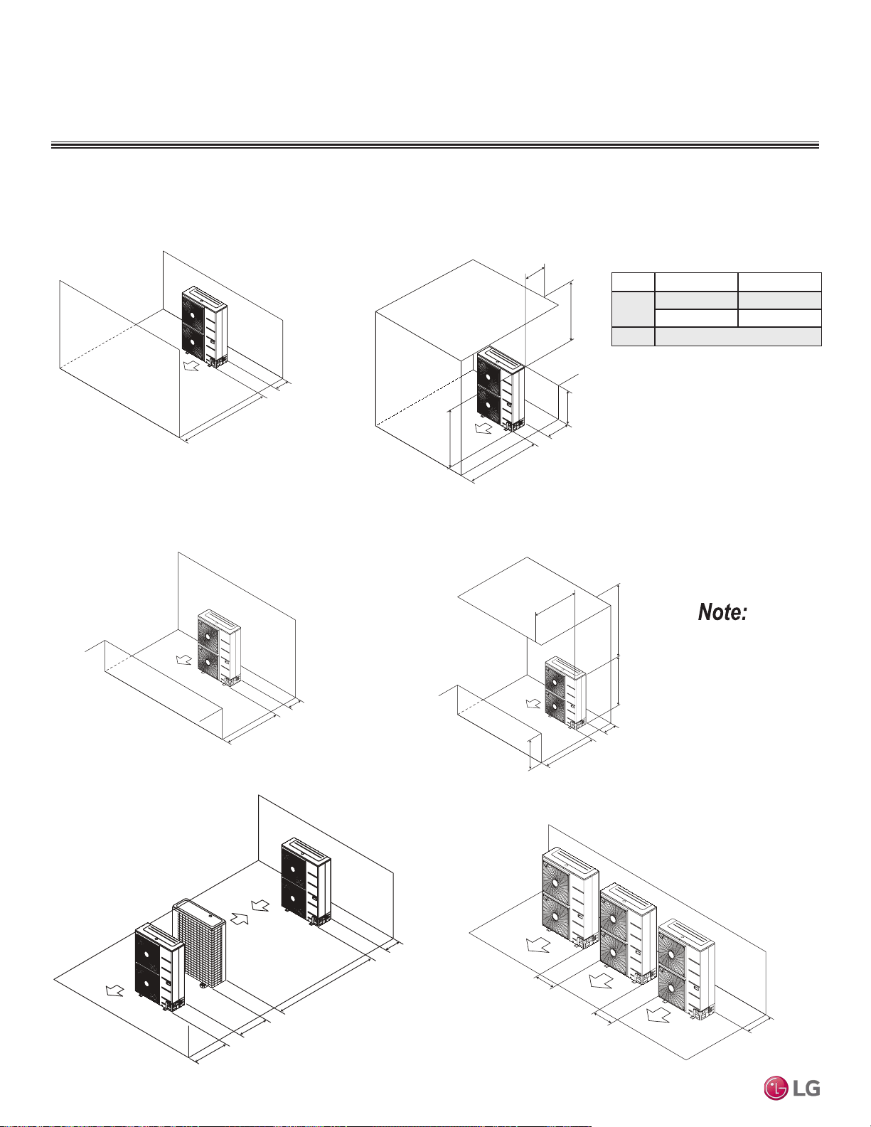
Where there are obstacles on both suction
and discharge sides (discharge side obstacle
is higher than the outdoor unit).
Minimum 19-11/16"
Minimum 11-13/16"
Table 121: Ratio among H, A, and L.
Clearance Requirements when Different Obstacles are Present, continued. (Unit: Inch)
If a stand is necessary, it must be contained (not open
frame) to prevent the discharge air from short cycling.
L A
L
≤ H
0 < L ≤ 1/2 H 29-1/32 inches
1/2 H < L 39-3/8 inches
H < L
Set Stand as: L ≤ H
Where there are obstacles above, and on both
suction and discharge sides (discharge side obstacle
is higher than the outdoor unit).
Maximum 19-11/16"
Minimum 11-13/16"
Minimum 39-3/8"
L
H
A
L
Minimum 39-3/8"
Minimum 39-3/8
"
Maximum 19-11/16"
Minimum 11-13/16"
Where there are obstacles on both suction
and discharge sides (discharge side obstacle
is lower than the outdoor unit).
Where there are obstacles above, and on both
suction and discharge sides (discharge side obstacle
is lower than the outdoor unit).
Minimum 19-11/16"
Minimum 11-13/16"
H
Minimum 11-13/16"
Minimum 78-3/4"
Minimum 23-19/32"
Minimum 39-3/8"
Series installation
“L” must be lower
than “H”. If a stand is
necessary, it must be
contained (not open
frame) to prevent the
discharge air from
short cycling.
PLACEMENT CONSIDERATIONS
Minimum 12"
Minimum 24"
Minimum 24"
Side-by-side series installation.
Due to our policy of continuous product innovation, some specications may change without notication.
©LG Electronics U.S.A., Inc., Englewood Cliffs, NJ. All rights reserved. “LG” is a registered trademark of LG Corp.
218 | APPLICATION GUIDELINES
Multi F and Multi F MAX Indoor Unit Engineering Manual
MULTI
F
MAX
MULTI
F

“Design Guideline Summary” on page 220
“Creating a Balanced System” on page 224
“Condensate Drain Piping” on page 225
REFRIGERANT PIPING
DESIGN & LAYOUT
BEST PRACTICES
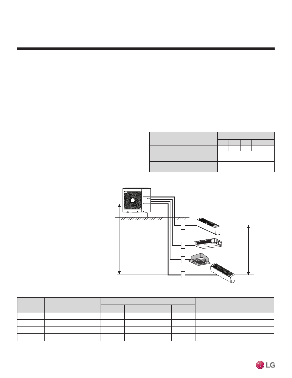
Device Connection Limitations
• The minimum number of connected and operating indoor units to Multi F / Multi F MAX systems is two, taking into consideration of the
minimum combination ratio.
• The maximum number of indoor units for each Multi F / Multi F MAX heat pump systems is:
REFRIGERANT PIPING DESIGN
Design Guideline Summary
One of the most critical elements of multi-zone systems is the refrigerant piping. The following pages list pipe length limits that must be
followed in the design of Multi F and Multi F MAX refrigerant pipe systems:
Table 122:Equivalent Piping Length for Elbows, Y-branches, and Branch
Distribution Units.
Max. 49.2 feet
Max. 24.6 feet
A
B
C
D
Multi F System
Example: LMU36CHV outdoor unit with four (4)
indoor units connected.
ODU: Outdoor Unit.
IDU: Indoor Unit.
A, B, C, D: Pipes from Outdoor Unit to Indoor Unit.
1
Kit contains two Y-branches: one for liquid and one for vapor.
Table 123:Multi F Outdoor Unit Refrigerant Piping System Limitations.
Component
Size (Inches)
1/4 3/8 1/2 5/8 3/4
Elbow (ft.)
0.5 0.6 0.7 0.8 1.2
Y-Branch Kit (ft., Multi F MAX systems
only)
1
1.6
Branch Distribution Unit (ft., Multi F
MAX systems only)
8.2
Field-supplied elbows are allowed as long as they are designed for
use with R410A refrigerant. The designer, however, must be cau-
tious with the quantity and size of fittings used, and must account for
the additional pressure losses in equivalent pipe length calculation
for each branch. The equivalent pipe length of each elbow must be
added to each pipe segment.
Using Refrigerant Components
The following are examples of manual pipe size calculations. Designers are highly encouraged to use LATS for Multi F systems.
LMU18CHV = 2 LMU24CHV = 3 LMU30CHV = 4 LMU36CHV = 4 LMU480HV = 8 LMU540HV = 8 LMU600HV = 8
Outdoor Unit
Minimum Length for Each
Pipe (ft.)
Maximum Piping Length to Each Indoor Unit (ft.)
Maximum Total Piping Length for Each
System (ft.)
A B C D
LMU18CHV 10 82 82 - - 164
LMU24CHV 10 82 82 82 - 246.1
LMU30CHV 10 82 82 82 82 246.1
LMU36CHV 10 82 82 82 82 246.1
LMU180HHV = 2 LMU240HHV = 3 LMU300HHV = 4 LMU360HHV = 5 LMU420HHV = 6
Due to our policy of continuous product innovation, some specications may change without notication.
©LG Electronics U.S.A., Inc., Englewood Cliffs, NJ. All rights reserved. “LG” is a registered trademark of LG Corp.
220 | DESIGN & PRACTICES
Multi F and Multi F MAX Indoor Unit Engineering Manual
MULTI
F
MAX
MULTI
F
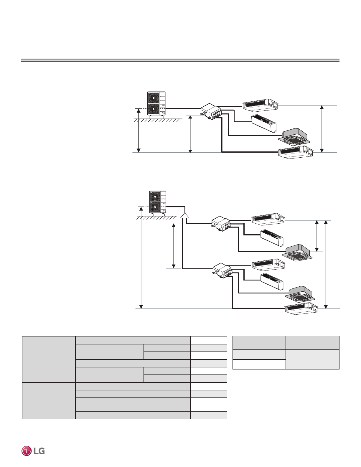
Design Guideline Summary
Example: LMU540HV outdoor unit with
seven (7) indoor units, and two (2)
branch distribution units connected.
ODU: Outdoor Unit.
IDU: Indoor Unit.
BD: Branch Distribution Unit(s).
ΣA: Main Pipe.
ΣB: Branch Pipe (Branch Distribution Unit[s] to
Indoor Unit[s]).
B
A
h2 ≤ 49.2 feet
A
h3 ≤ 32.8 feet
h4 ≤ 49.2 feet
h1 ≤ 98.4 feet
BDU Y-Branch
BDU
IDU
A
ODU
IDU
IDU
IDU
IDU
IDU
IDU
B
B
B
B
B
B
Table 124: Multi F MAX Outdoor Unit Refrigerant Piping System Limitations.
Pipe Length
(ELF = Equivalent
Length of pipe in Feet)
Total piping length (ΣA + ΣB)
≤475.7 feet
Main pipe (Outdoor Unit to
Branch Distribution Units: ΣA)
Minimum
10 feet
Maximum
≤180.4 feet
Total branch piping length (ΣB)
≤295.3 feet
Branch pipe (Branch Distribu-
tion Units to Indoor Units: B)
Minimum
10 feet
Maximum
≤49.2 feet
Elevation Differential
(All Elevation
Limitations are
Measured in Actual
Feet)
If outdoor unit is above or below indoor unit (h1)
≤98.4 feet
Between the farthest two indoor units (h2)
≤49.2 feet
Between branch distribution unit and farthest
connected indoor unit(s) (h3)
≤32.8 feet
Between branch distribution units (h4)
≤49.2 feet
Table 125: Multi F MAX Piping Sizes.
Piping
Main Pipe A
(inch)
Branch Pipe B
Liquid Ø3/8
Depends on the size
of the indoor unit piping
Gas Ø3/4
Example: LMU540HV outdoor unit with
four (4) indoor units, and one (1) branch
distribution unit connected.
ODU: Outdoor Unit.
IDU: Indoor Unit.
BDU: Branch Distribution Unit.
A: Main Pipe.
B: Branch Pipe (Branch Distribution Unit to
Indoor Unit[s]).
A
h2 ≤ 49.2 feet
h3 ≤ 32.8 feet
h1 ≤ 98.4 feet
BDU
ODU
IDU
IDU
IDU
IDU
B
B
B
B
Multi F MAX System with One Branch Distribution Unit
Multi F MAX System with Two Branch Distribution Units
The following are examples of manual pipe size calculations. Designers are highly encouraged to use LATS for Multi F systems.
REFRIGERANT PIPING DESIGN
Due to our policy of continuous product innovation, some specications may change without notication.
©LG Electronics U.S.A., Inc., Englewood Cliffs, NJ. All rights reserved. “LG” is a registered trademark of LG Corp.
DESIGN & PRACTICES | 221
Refrigerant Piping Design and Best Practices
MULTI
F
MAX
MULTI
F
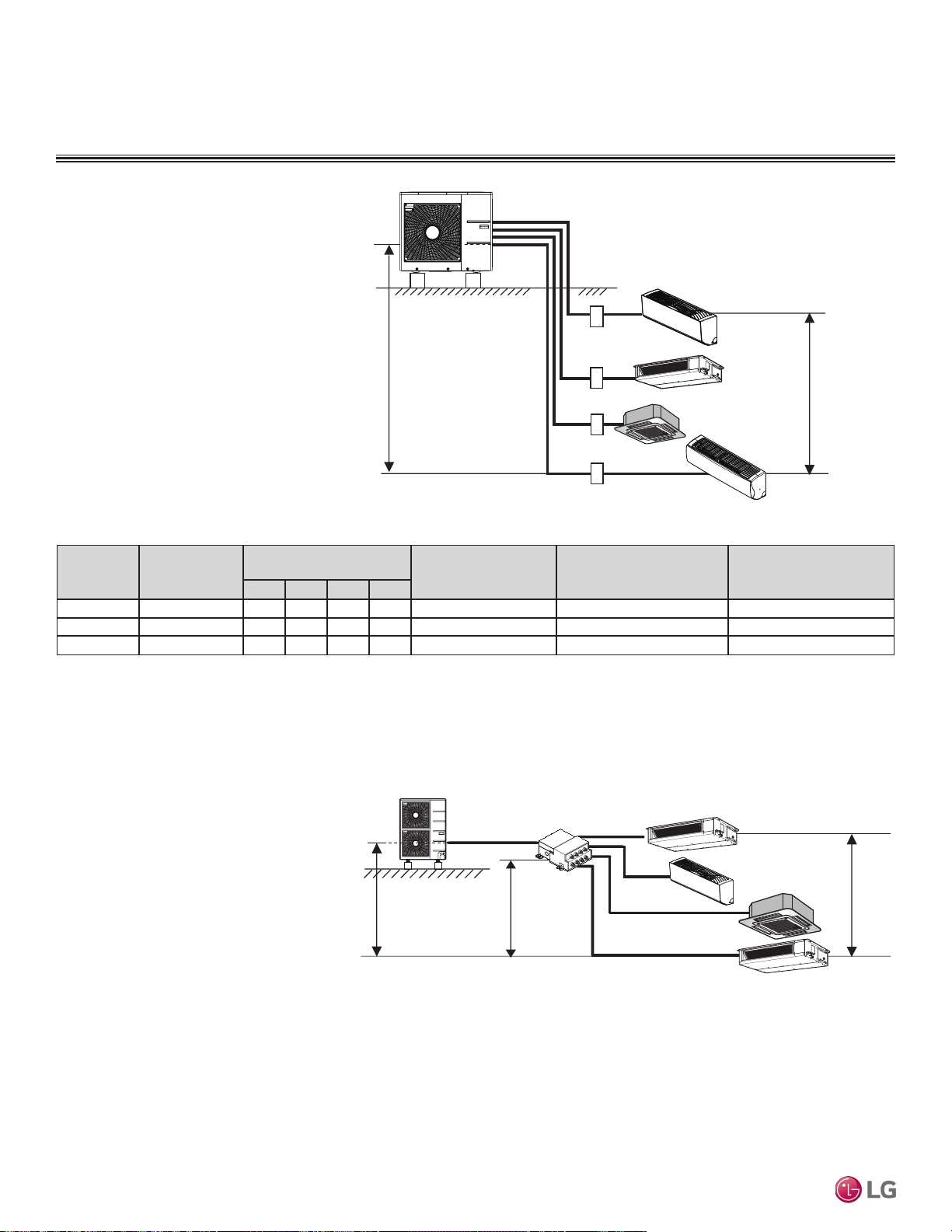
REFRIGERANT PIPING DESIGN
Design Guideline Summary
The following are examples of manual pipe size calculations. Designers are highly encouraged to use LATS for Multi F systems.
Max. 49.2 feet
Max. 24.6 feet
A
B
C
D
Multi F with LGRED System
Example: LMU300HHV outdoor unit with four (4)
indoor units connected.
ODU: Outdoor Unit.
IDU: Indoor Unit.
A, B, C, D: Pipes from Outdoor Unit to Indoor Unit.
Outdoor Unit
Minimum Length
for Each Pipe
(ft.)
Maximum Piping Length to
Each Indoor Unit (ft.)
Maximum Total Piping
Length for Each System
(ft.)
Maximum Height Difference
(Max. [ft.])
Outdoor Unit ~ Indoor Unit
Maximum Height Difference
(Max. [ft.])
Indoor Unit ~ Indoor Unit
A B C D
LMU180HHV 10 82 82 - - 164 49.2 24.6
LMU240HHV 10 82 82 82 - 246.1 49.2 24.6
LMU300HHV 10 82 82 82 82 246.1 49.2 24.6
Table 126:Multi F with LGRED Outdoor Unit Refrigerant Piping System Limitations.
Example: LMU360HHV outdoor unit with
four (4) indoor units and one (1) branch
distribution unit connected.
ODU: Outdoor Unit.
IDU: Indoor Unit.
BDU: Branch Distribution Unit.
A: Main Pipe.
B: Branch Pipe (Branch Distribution Unit to
Indoor Unit[s]).
Multi F MAX with LGRED System with One Branch Distribution Unit
A
h2 ≤ 49.2 feet
h3 ≤ 32.8 feet
h1 ≤ 98.4 feet
BDU
ODU
IDU
IDU
IDU
IDU
B
B
B
B
Due to our policy of continuous product innovation, some specications may change without notication.
©LG Electronics U.S.A., Inc., Englewood Cliffs, NJ. All rights reserved. “LG” is a registered trademark of LG Corp.
222 | DESIGN & PRACTICES
Multi F and Multi F MAX Indoor Unit Engineering Manual
MULTI
F
MAX
MULTI
F
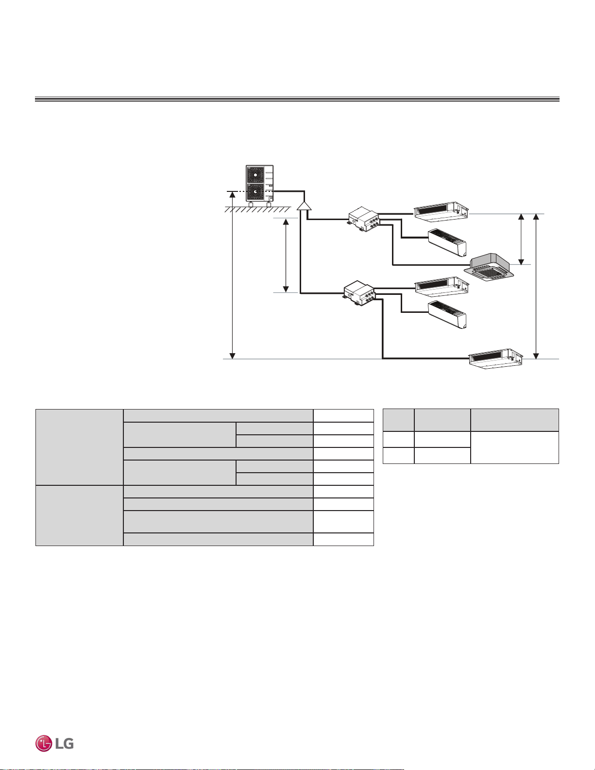
Design Guideline Summary
The following are examples of manual pipe size calculations. Designers are highly encouraged to use LATS for Multi F systems.
REFRIGERANT PIPING DESIGN
B
A
h2 ≤ 49.2 feet
A
h3 ≤ 32.8 feet
h4 ≤ 49.2 feet
h1 ≤ 98.4 feet
BDU Y-Branch
BDU
IDU
A
ODU
IDU
IDU
IDU
IDU
IDU
B
B
B
B
B
Multi F MAX with LGRED System with Two Branch Distribution Units
Example: LMU420HHV outdoor unit with
six (6) indoor units and two (2) branch
distribution units connected.
ODU: Outdoor Unit.
IDU: Indoor Unit.
BDU: Branch Distribution Unit(s).
ΣA: Main Pipe.
ΣB: Branch Pipe (Branch Distribution Unit[s] to
Indoor Unit[s]).
Table 127: Multi F MAX with LGRED Outdoor Unit Refrigerant Piping System Limitations.
Pipe Length
(ELF = Equivalent
Length of pipe in Feet)
Total piping length (ΣA + ΣB)
≤475.7 feet
Main pipe (Outdoor Unit to
Branch Distribution Units: ΣA)
Minimum
10 feet
Maximum
≤180.4 feet
Total branch piping length (ΣB)
≤295.3 feet
Branch pipe (Branch Distribu-
tion Units to Indoor Units: B)
Minimum
10 feet
Maximum
≤49.2 feet
Elevation Differential
(All Elevation
Limitations are
Measured in Actual
Feet)
If outdoor unit is above or below indoor unit (h1)
≤98.4 feet
Between the farthest two indoor units (h2)
≤49.2 feet
Between branch distribution unit and farthest
connected indoor unit(s) (h3)
≤32.8 feet
Between branch distribution units (h4)
≤49.2 feet
Table 128: Multi F MAX with LGRED Piping Sizes.
Piping
Main Pipe A
(inch)
Branch Pipe B
Liquid Ø3/8
Depends on the size
of the indoor unit piping
Gas Ø3/4
Due to our policy of continuous product innovation, some specications may change without notication.
©LG Electronics U.S.A., Inc., Englewood Cliffs, NJ. All rights reserved. “LG” is a registered trademark of LG Corp.
DESIGN & PRACTICES | 223
Refrigerant Piping Design and Best Practices
MULTI
F
MAX
MULTI
F
Creating a Balanced / Quality Piping System
Unlike designing duct-work or chilled and hot water pipe systems where balancing dampers, ball valves, orifices, circuit setters, or other
flow control devices can be installed to modify or balance the flow of cooling medium, these cannot be used in a Multi F system. Therefore,
variable refrigerant flow systems have to be designed to be “self balanced.” Balanced liquid refrigerant distribution is solely dependent on
the designer using the correct pipe size for each segment. Pipe sizing considerations include pipe length, pipe segment pressure drop
relative to other pipe segments in the system, type and quantity of elbows, bends present, fitting installation orientation, and end use device
elevation differences.
Any eld changes, such as re-routing, shortening or lengthening a pipe segment, adding or eliminating elbows and/or ttings, re-sizing, adding,
or eliminating indoor units, changing the mounting height or moving the location of a device or tting during installation must be done with cau-
tion and ALWAYS VERIFIED in LATS HVAC SOFTWARE before supplies are purchased or installed. Doing so ensures protable installation,
eliminates rework, and ensures easier system commissioning.
The designer must avoid creating excessive pressure drop. When liquid refrigerant is subjected to excessive pressure drop, liquid re-
frigerant will change state and “ash” to vapor. Vapor present in a stream of liquid refrigerant before reaching the indoor unit coil (or branch
distribution unit for Multi F MAX systems) results in a loss of system control and causes damage to the components. The pipe system must
be designed in a manner that avoids the creation of unwanted vapor.
Refrigerant Piping System Verification
To ensure that the refrigerant piping design is suitable for the system, a LATS refrigerant piping design software report must be provided with
every Multi F order. Following the installation, if any changes or variations to the design were necessary, an “as-built” LATS piping design
software report must be provided to LG prior to system commissioning. User must always check the LATS report actual pipe layout versus
pipe limits.
REFRIGERANT PIPING DESIGN
Manual Layout Procedure
1. Choose the location of the indoor units on the building drawing.
2. Choose the location of all Y-branch and branch distribution units (if a Multi F MAX system) and note them on the building drawing. Verify
that all fittings are positioned per the guideline limitations in “LG Engineered Multi F MAX Y-Branch Kit”
3. Plan the route for interconnecting piping. Draw a one-line depiction of the pipe route chosen on the building drawing.
4. Calculate the actual length of each pipe segment and note it on the building drawing.
5. Using the data obtained while selecting the system components, list the corrected cooling capacity next to each indoor unit on the drawing.
6. Starting at the indoor unit located farthest from the outdoor unit, sum the corrected cooling capacity of all indoor units served by the pipe
segment for each branch and runout pipe (indoor units and branch distribution units [Multi F MAX systems only]). Record these values
next to each segment.
7. Verify the size of the liquid and vapor lines.
8. If a Multi F MAX system, refer to the branch distribution unit information and the Y-branch kit information to verify the part number of each
Y-branch and branch distribution unit based on the connected downstream nominal capacity served.
9. Calculate the equivalent pipe length in feet of each pipe segment. If a Multi F MAX system, Y-branch equivalent lengths must be totaled
with the upstream segment only. Use equivalent pipe length data when it is provided with field-purchased fittings. If not available, use the
data provided to estimate the equivalent length of field-provided pipe and fittings for each segment. Equivalent lengths must be totaled
with the upstream segment only.
10. Verify the equivalent pipe length complies with product limitations. If the limitations are exceeded, either reroute the pipe or change the
location of the indoor unit, Y-branch fittings and branch distribution units (if Multi F MAX systems), so the design conforms with all limita-
tions.
11. If pipe length is adjusted as described in Step 10 above, verify again if the length of the design complies with the product limitations.
12. Use LATS HVAC software to verify the manually sized pipe design is acceptable. When entering the length of pipe segments in LATS
HVAC software, enter the equivalent pipe length. Account for the additional pressure drop created by elbows, valves, and other fittings
present in each segment by adding their respective equivalent pipe length to the actual pipe length.
Creating a Balanced System / Manual Layout Procedure
Due to our policy of continuous product innovation, some specications may change without notication.
©LG Electronics U.S.A., Inc., Englewood Cliffs, NJ. All rights reserved. “LG” is a registered trademark of LG Corp.
224 | DESIGN & PRACTICES
Multi F and Multi F MAX Indoor Unit Engineering Manual
MULTI
F
MAX
MULTI
F

INSTALLATION & LAYOUT BEST PRACTICES
Condensate Drain Piping
Indoor Units
All indoor units generate water during cooling operation, therefore, how to properly handle this condensation must be considered. Some
indoor units include factory-installed drain pumps; others apply the gravity drain method.
Condensate Drain Piping
Indoor Unit Drain Type Drain Pipe Diameter (OD / ID, in.)
Drain Amount
(gal. / min. at 0.033 ft. height)
Art Cool Wall-Mounted Gravity 13/16 / 5/8 —
Art Cool Gallery Gravity 13/16 / 5/8 —
Standard Wall-Mounted Gravity 13/16 / 5/8 —
Low Wall Console Gravity 13/16 / 5/8 —
Ceiling-Concealed Ducted
(Low Static and High Static)
27-1/2 in. Lift Drain Pump,
Factory Installed
Ø1-1/4 / Ø1 0.105
Four-Way Ceiling Cassette
27-1/2 in. (9,12MBh) or
31-1/2 in (18MBh) Lift Drain Pump,
Factory Installed
Ø1-1/4 / Ø1 0.105
Vertical-Horizontal Air Handling Unit Gravity Ø3/4 / — —
Table 129:Indoor Unit Drain Piping Specications.
Flexible hose
Drain pump
PVC elbow
PVC
PVC
1/50~1/100 slope
≤Max. 27-1/2 in. (Ducted and
9/12MBh Cassette)
≤Max. 31-1/2 in. (18MBh Cassette)
≤11-13/16 in.
Metal clamp
Drain pan
Insulation
Flexible drain hose
Insulation
Figure 280:Diagram of an Indoor Unit with a Gravity Drain. Figure 281:Diagram of an Indoor Unit with a Drain Pump.
Due to our policy of continuous product innovation, some specications may change without notication.
©LG Electronics U.S.A., Inc., Englewood Cliffs, NJ. All rights reserved. “LG” is a registered trademark of LG Corp.
DESIGN & PRACTICES | 225
Refrigerant Piping Design and Best Practices
MULTI
F
MAX
MULTI
F

“General Information” on page 227
“Power Wiring (208-230V) and Communications Cable
Details” on page 230
“Remote Controller Connections” on page 240
“Indoor Unit Group Control” on page 241
ELECTRICAL
CONNECTIONS
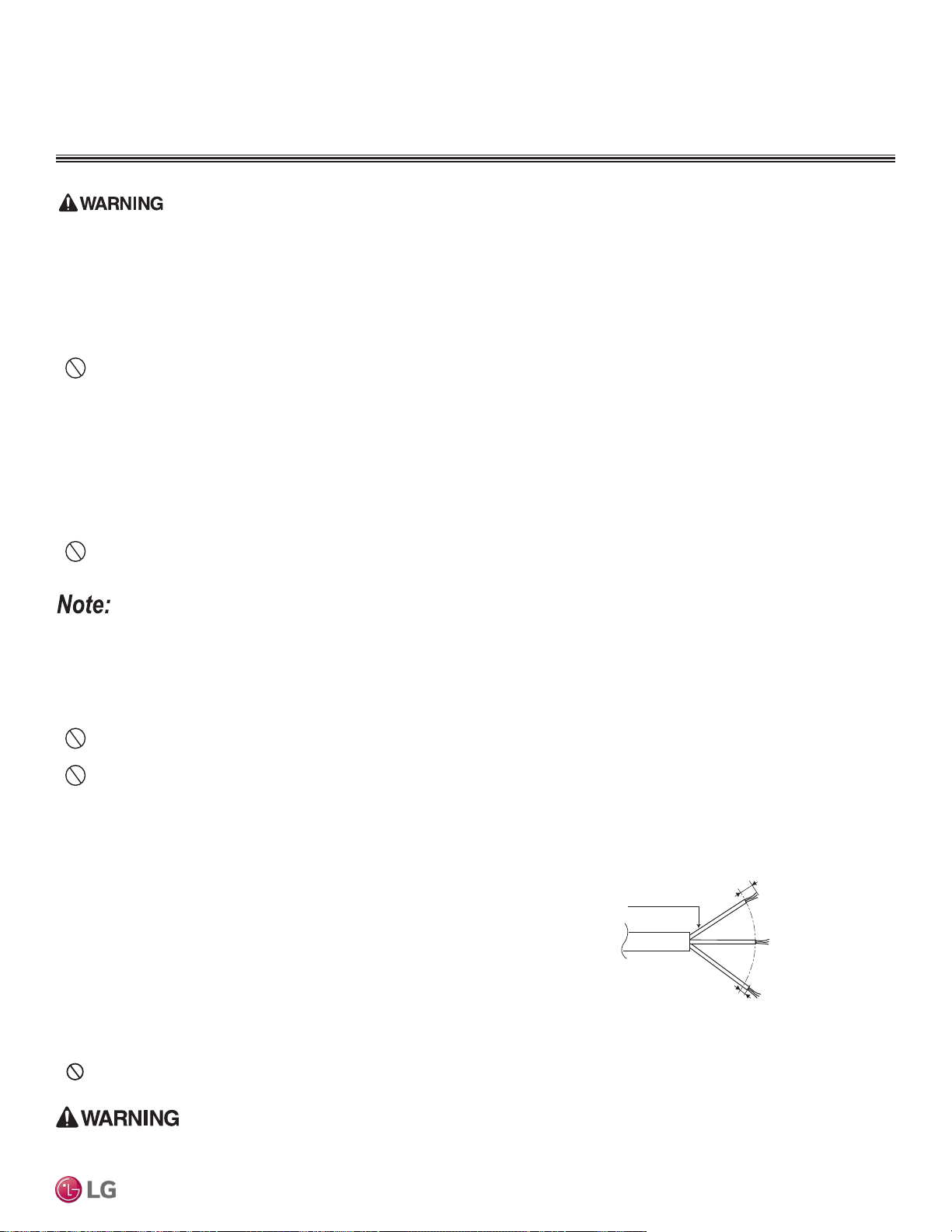
Always have a trained service provider properly ground the outdoor unit. If the outdoor unit is not properly grounded, there is a risk of electric shock,
physical injury, or death.
• Multi F systems operate at 1Ø, 208-230V, 60Hz, and power is wired to the outdoor unit
only. The outdoor unit will supply power to the indoor units and the branch distribution
units (Multi F MAX systems only) through the communication / connection (power) cable.
• Power supply to the outdoor unit must be selected based on NEC and local codes. Maxi-
mum allowable voltage fluctuation ±10% or nameplate rated value.
• Power wiring to the outdoor unit(s) must be solid or stranded, and must comply with all
local and national electrical codes.
• Properly ground the outdoor unit and indoor unit per NEC and local codes.
• Ground wire must be longer than the common power / communication wires.
• Connect the wiring firmly so the wires cannot be easily pulled out.
• Refer to the inside of the chassis cover or control cover for circuit and terminal block diagrams.
• Always match color codes of each wire and follow wiring diagram.
•
Do not install power wiring to the outdoor unit and the communication / connection (power) cable to the indoor unit in the same conduit.
Use separate conduits.
Power Supply / Power Wiring Specifications
Figure 282: Multi F / Multi F MAX Outdoor Unit
Power Wiring.
7/16" ± 1/8"
13/16
"
GN/YL
Power Wiring, Ground
to Outdoor Unit
General Information
ELECTRICAL CONNECTIONS
• All power (line voltage) wiring and communication cable installation must be performed by trained service providers working in accordance
with all local, state, and National Electrical Code (NEC) / UL / ETL federal regulations related to electrical equipment and wiring, and following
the manufacturer product diagrams, requirements, and instructions in this manual. Electric shock can cause physical injury or death.
• Be sure that main power to the unit is completely off before proceeding. Follow all safety and warning information outlined at the beginning of
this manual. Failure to do so will cause electric shock and bodily injury.
• Install a main shutoff switch or circuit breaker that interrupts all power sources simultaneously (circuit breaker must be resistant to electro-
magnetic currents). Be sure that the circuit breaker or some other emergency power cutoff device is in place before any power wiring is done
to the system. Failure to do so will cause bodily injury or death.
•
Never touch any power lines or live cables before all power is cutoff to the system. To do so will cause bodily injury or death.
• Power wiring and communication cable sizes must comply with all applicable federal, state, and local codes. Undersized wiring will lead to
unacceptable voltage at the unit and will cause a fire, which will cause bodily injury or death.
• Properly ground the outdoor unit, indoor units, and branch distribution units. Ground wiring must always be installed by a trained technician.
Ground wiring is required to prevent accidental electrical shock during current leakage, which will cause bodily injury or death.
• Verify that the branch switch and circuit breaker are set to OFF before installing the wiring system. Electric shock can cause physical injury
or death.
• Install appropriately sized breakers / fuses / overcurrent protection switches and wiring in accordance with local, state, and NEC regulations
related to electrical equipment and wiring, and following the instructions in this manual. Generated overcurrent will include some amount of
direct current. Using an oversized breaker or fuse will result in electric shock, physical injury or death.
• Do not connect ground wire to refrigerant, gas, sewage, or water piping; to lightning rods; to telephone ground wiring; or to the building
plumbing system. Failure to properly provide a NEC-approved earth ground can result in electric shock, fire, physical injury or death.
• Consider ambient conditions (temperature, direct sunlight, inclement weather, etc.) when selecting, installing, and connecting the power wiring.
• Properly ground the outdoor unit, indoor units, and branch distribution units. Ground wiring must always be installed by a trained technician.
Improperly grounded wire can cause communication problems from electrical noise, and motor current leakage.
• Install appropriately sized breakers / fuses / overcurrent protection switches and wiring in accordance with local, state, and NEC regulations
related to electrical equipment and wiring, and following the instructions in this manual. Generated overcurrent will include some amount of
direct current. Using an oversized breaker or fuse will result in equipment malfunction and property damage.
• Do not connect ground wire to refrigerant, gas, or water piping; to lightning rods; to telephone ground wiring; or to the building plumbing
system. Failure to properly provide a NEC-approved earth ground can result in property damage and equipment malfunction.
• Do not operate the air conditioning system until the refrigerant piping installation is complete. Operating the system before refrigerant
piping is finalized will damage the compressor.
Due to our policy of continuous product innovation, some specications may change without notication.
©LG Electronics U.S.A., Inc., Englewood Cliffs, NJ. All rights reserved. “LG” is a registered trademark of LG Corp.
WIRING CONNECTIONS | 227
Wiring Connections
MULTI
F
MAX
MULTI
F
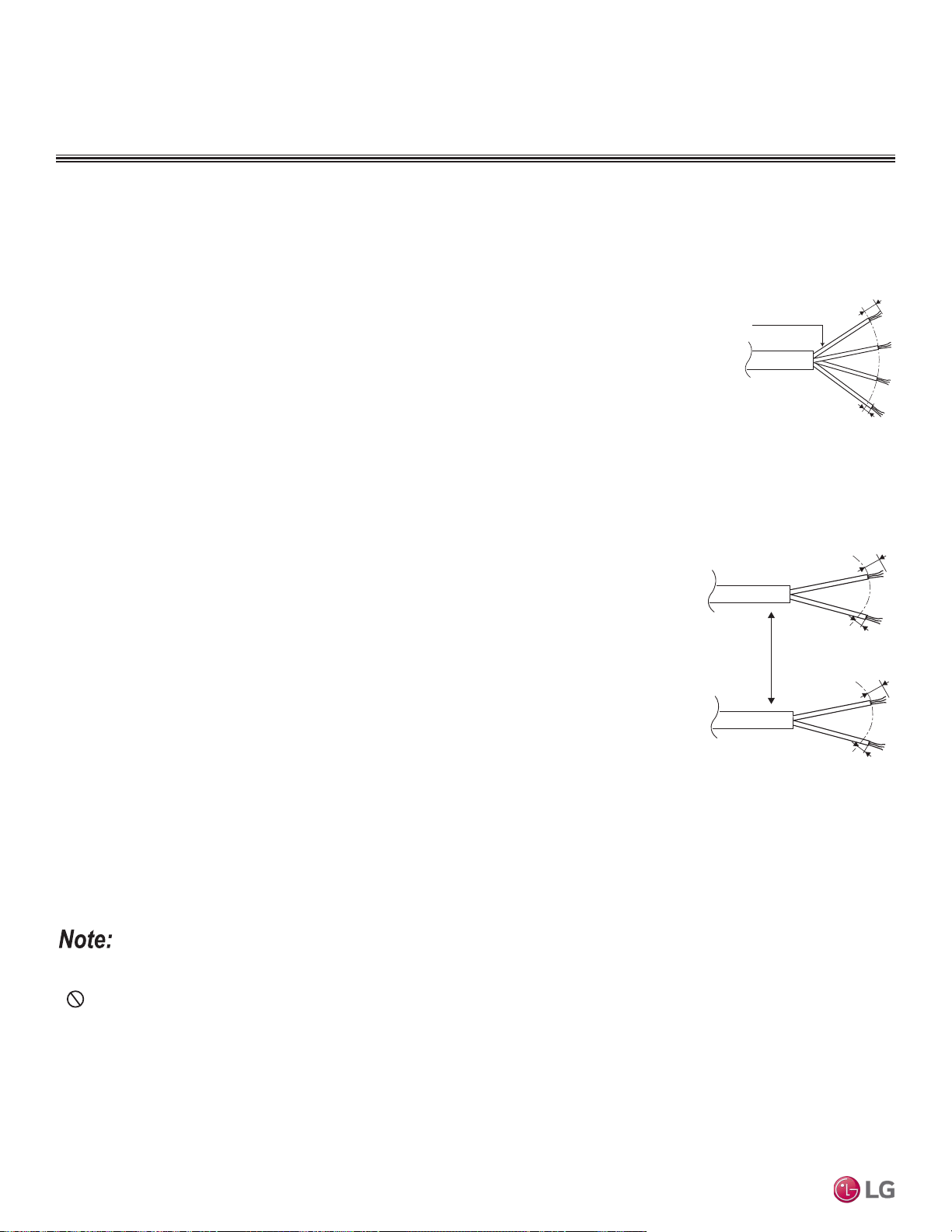
General Information
ELECTRICAL CONNECTIONS
Multi F Systems:
• Communication / connection (power) cable from the outdoor unit to the indoor unit for
lengths up to 130 feet must use a minimum of 14 AWG, four (4) conductor, stranded,
shielded or unshielded (if shielded, it must be grounded to the chassis of the outdoor
unit only), and must comply with applicable local and national codes.
• When the communication / connection (power) wires between the indoor unit and
outdoor unit is GREATER THAN 130 feet, use:
• A two (2) conductor wire for power (for each indoor unit).
• A two (2) conductor wire for communication / ground (for each indoor unit).
• Separate the power AT LEAST two (2) inches away from the communication /
ground wire (for each indoor unit).
• All wiring is still minimum 14 gauge, stranded, shielded, or unshielded as cited
above (for each indoor unit).
Multi F MAX Systems:
• All communication / connection (power) cable from the outdoor unit to the branch
distribution unit(s) must be a minimum of 14 AWG, four (4) conductor, stranded,
shielded or unshielded (if shielded, it must be grounded to the chassis of the outdoor
unit only), and must comply with applicable local and national codes.
• Communication / connection (power) cable from the branch distribution unit(s) to
the indoor units for lengths up to 130 feet must use a minimum of 14 AWG, four (4)
conductor, stranded, shielded or unshielded (if shielded, it must be grounded to the
chassis of the outdoor unit only), and must comply with applicable local and national
codes.
• When the communication / connection (power) wires between the branch distribution
unit and indoor unit is GREATER THAN 130 feet, use:
• A two (2) conductor wire for power (for each indoor unit).
• A two (2) conductor wire for communication / ground (for each indoor unit).
• Separate the power AT LEAST two (2) inches away from the communication /
ground wire (for each indoor unit).
• All wiring is still minimum 14 gauge, stranded, shielded, or unshielded as cited
above (for each indoor unit).
• Insulation material as required by local code.
• Rated for continuous exposure of temperatures up to 140°F.
• Firmly attach the cable; provide slack but secure in a way to prevent external forces from being imparted on the terminal block.
• Wiring must be completed without splices.
Communication / Connection (Power) Cable Specifications
Figure 283:Typical Multi F / Multi F MAX with
LGRED Outdoor and Indoor / Branch Distribution
Unit Wiring and Communications Cable Diagram
For Wiring Lengths Up to 130 Feet.
Power Wiring, Ground,
Communication Cable
From Outdoor Unit
To Indoor Unit or from the
Outdoor Unit to the Branch
Distribution Unit
13/16”
GN/YL
GN/YL = (Ground, Yellow)
7/16" ± 1/8"
Two-Conductor
Power Cable
GN/YL
GN/YL = (Ground, Yellow)
Two-Conductor
Communication /
Ground Cable
Separate At Least
Two (2) Inches
13/16"
7/16" ± 1/8"
1(L1)
2(L2)
13/16"
7/16" ± 1/8"
3
Figure 284:Multi F with LGRED Outdoor Unit to
Indoor Unit, and Multi F MAX with LGRED Branch
Distribution Unit to Indoor Unit Wiring Diagram for
Wiring Lengths GREATER THAN 130 Feet.
• Use a conduit for the communications / connection (power) cable from the outdoor unit to the indoor units and branch distribution unit(s).
Electrical interference my cause product malfunction.
•
Never ground the shield of the communications cable to the indoor unit frame or other grounded entities of the building. Ground the com-
munications cable shield only at the outdoor unit. Improperly grounding this cable can cause communications errors.
• The communications / connection (power) cable from the outdoor unit to the indoor units / branch distribution unit(s) must be separated and
isolated from power wiring to the outdoor unit, computers, radio and television broadcasting facilities, as well as medical imaging equipment.
Electrical interference my cause product malfunction.
Due to our policy of continuous product innovation, some specications may change without notication.
©LG Electronics U.S.A., Inc., Englewood Cliffs, NJ. All rights reserved. “LG” is a registered trademark of LG Corp.
228 | WIRING CONNECTIONS
Multi F and Multi F MAX Indoor Unit Engineering Manual
MULTI
F
MAX
MULTI
F
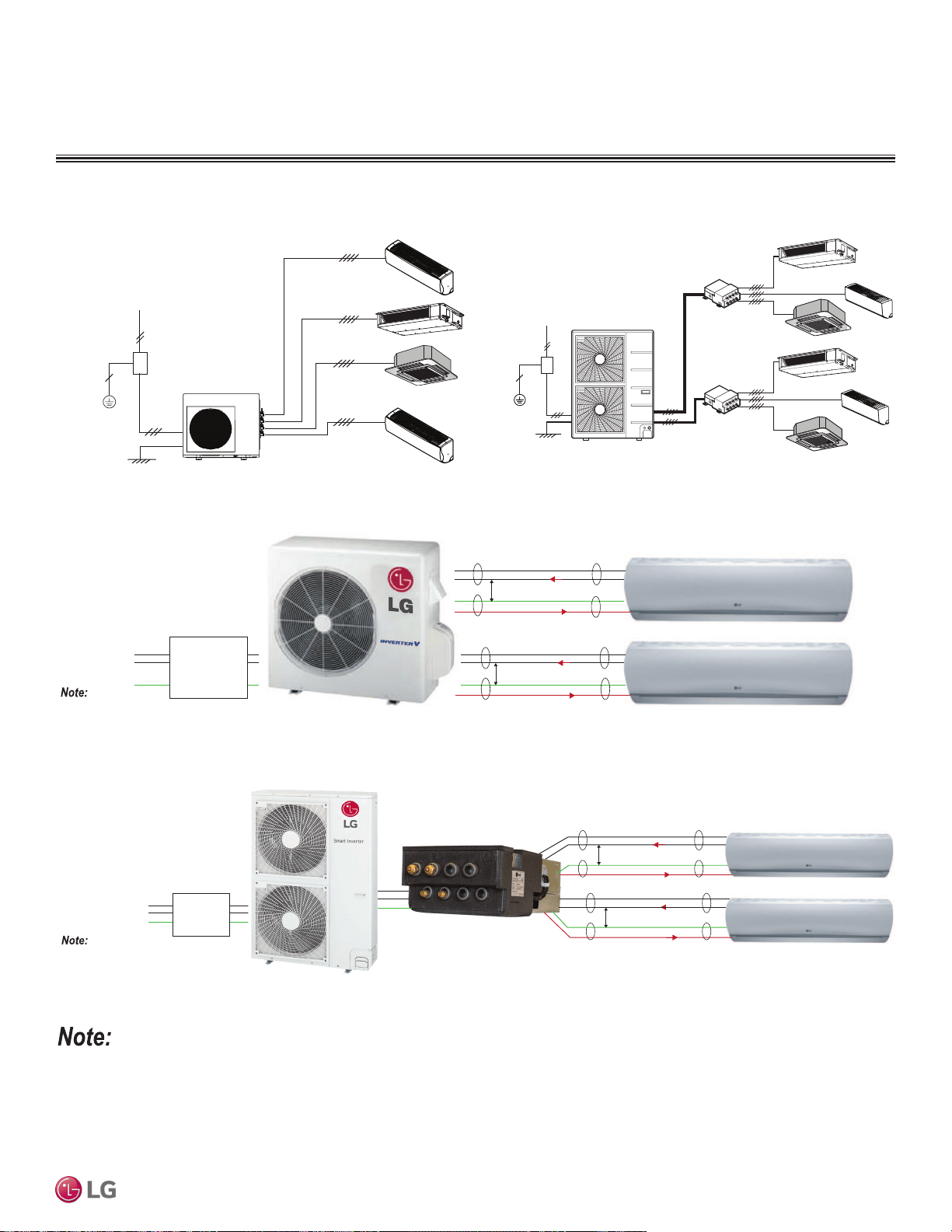
• Secure the separate wires in the control box panel using zip ties.
• Secure wiring with accessory clamps so that it does not touch piping.
• Use a conduit for the cable.
• Outside the unit, make sure the communications cable / power wiring are separately shielded, otherwise, the outdoor unit operation will be
affected by electrical noise and will malfunction or fail.
• For details on the Multi F with LG RED and Multi F MAX with LG RED units, refer to the engineering manuals on www.lghvac.com.
General Information
ELECTRICAL CONNECTIONS
Figure 285:Typical Multi F System General Power / Communications
System Schematic When Wiring is Less Than 130 Feet.
Figure 286:Typical Multi F MAX System General Power / Communica-
tions System Schematic When Wiring is Less Than 130 Feet.
Power Supply
Circuit Breaker
Indoor Unit
Branch Distribution Unit
Ground Wiring
Outdoor Unit
Branch Distribution Unit
Indoor Units
Power Supply
Circuit Breaker
Ground Wiring
Outdoor Unit
Figure 287:Schematic of a Multi F System When the Wiring is GREATER THAN 130 Feet.
Figure 288:Schematic of a Multi F MAX with LGRED System When the Wiring is GREATER THAN 130 Feet.
Power
Supply
1(L1) (Power, L)
2(L2) (Neutral, N)
G (Ground)
Power Flow: L → N
Diagram is an example of communication and power
cables when the wiring is GREATER THAN 130 feet.
Terminals may be labeled differently depending on the model.
Outdoor and Indoor Unit appearances may vary depending on the model.
Communication Flow: Comm → N
3 (Communications)
GREATER THAN 130 feet: Must Separate Communications and Ground (G) Cable from the Power
(1[L1]) and Neutral (2[L2]) Cable at Least Two (2) Inches for Each Indoor Unit
At Least Two (2) Inches
3 (Communications)
At Least Two (2) Inches
Power
Supply
1(L1) (Power, L)
2(L2) (Neutral, N)
G (Ground)
Power Flow: L → N
Diagram is an example of communication and
power cables when the wiring is GREATER THAN
130 feet. Terminals may be labeled differently depending on the model.
Outdoor and Indoor Unit appearances may vary depending on the model.
Communication Flow: Comm → N
3 (Communications)
GREATER THAN 130 feet: Must Separate Communications and Ground (G) Cable
from the Power (1[L1]) and Neutral (2[L2]) Cable at Least Two (2) Inches for Each
Indoor Unit.
At Least Two (2) Inches
3 (Communications)
At Least Two (2) Inches
Due to our policy of continuous product innovation, some specications may change without notication.
©LG Electronics U.S.A., Inc., Englewood Cliffs, NJ. All rights reserved. “LG” is a registered trademark of LG Corp.
WIRING CONNECTIONS | 229
Wiring Connections
MULTI
F
MAX
MULTI
F
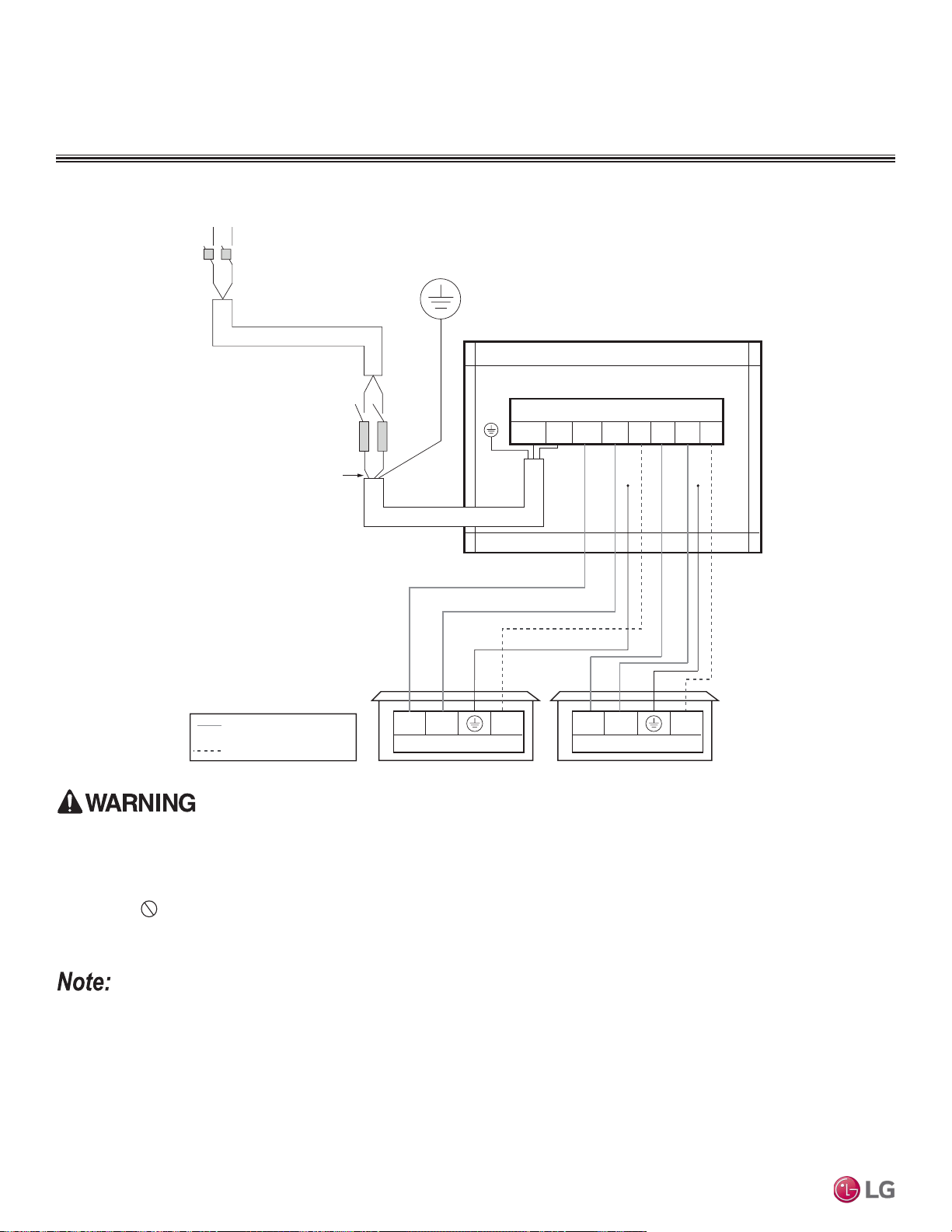
Figure 289: Multi F LMU18CHV System Power Wiring and Communications Cable.
Outdoor Unit
L1 L2 1(L1) 2(L2) 3(A) 3(B)
Outdoor Unit Terminal Block
L1
L1
L2
L2
G
Power Supply
Main Switch
Circuit Breaker
Fuse
Three-wire Power Wiring
(Including Ground)
COMMUNICATION CABLE
POWER WIRING
1(L1) 2(L2)
Indoor Unit Terminal Block
Unit A Unit B
3
1(L1) 2(L2) 3
Indoor Unit Terminal Block
G
1(L1) 2(L2)
Power Wiring (208-230V) and Communications Cable Details
ELECTRICAL CONNECTIONS
• All eld-supplied wiring, components, and materials must follow national, state, and local codes and requirements. Electric shock can cause physical
injury or death.
• Use only stranded, shielded or unshielded copper communications / power wiring from the outdoor unit to the indoor units. If shielded, wiring must be
grounded to the chassis at the outdoor unit only. Improper wiring will result in re, electric shock, physical injury or death.
• Ground wiring is required to prevent accidental electrical shock during current leakage, communication problems from electrical noise, and motor cur-
rent leakage. Do not connect the ground line to the pipes. Improper wiring will result in re, electric shock, physical injury or death.
• Install a main shutoff switch or circuit breaker that interrupts all power sources simultaneously. Electric shock can cause physical injury or death.
• Wiring cable size must comply with applicable national, state, and local codes. Improper wiring will result in re, electric shock, physical injury or death.
• For Multi F with LGRED, refer to Multi F & Multi F MAX with LGRED ODU engineering manual.
• Ground wiring is required to prevent communication problems from electrical noise, and motor current leakage. Failure to provide proper ground wiring
can result in property damage and equipment malfunction.
• All eld-supplied wiring, components, and materials must follow national, state, and local codes and requirements. Failure to install proper electrical
components can result in property damage and equipment malfunction.
• Use only stranded, shielded or unshielded copper communications / power wiring from the outdoor unit to the indoor units. If shielded, wiring must be
grounded to the chassis at the outdoor unit only. Failure to install proper wiring can result in property damage and equipment malfunction.
• Install a main shutoff switch or circuit breaker that interrupts all power sources simultaneously. Failure to install proper electric components can result in
property damage and equipment malfunction.
• Wiring cable size must comply with applicable national, state, and local codes. Improper wiring can result in property damage and equipment malfunction.
Due to our policy of continuous product innovation, some specications may change without notication.
©LG Electronics U.S.A., Inc., Englewood Cliffs, NJ. All rights reserved. “LG” is a registered trademark of LG Corp.
230 | WIRING CONNECTIONS
Multi F and Multi F MAX Indoor Unit Engineering Manual
MULTI
F
MAX
MULTI
F
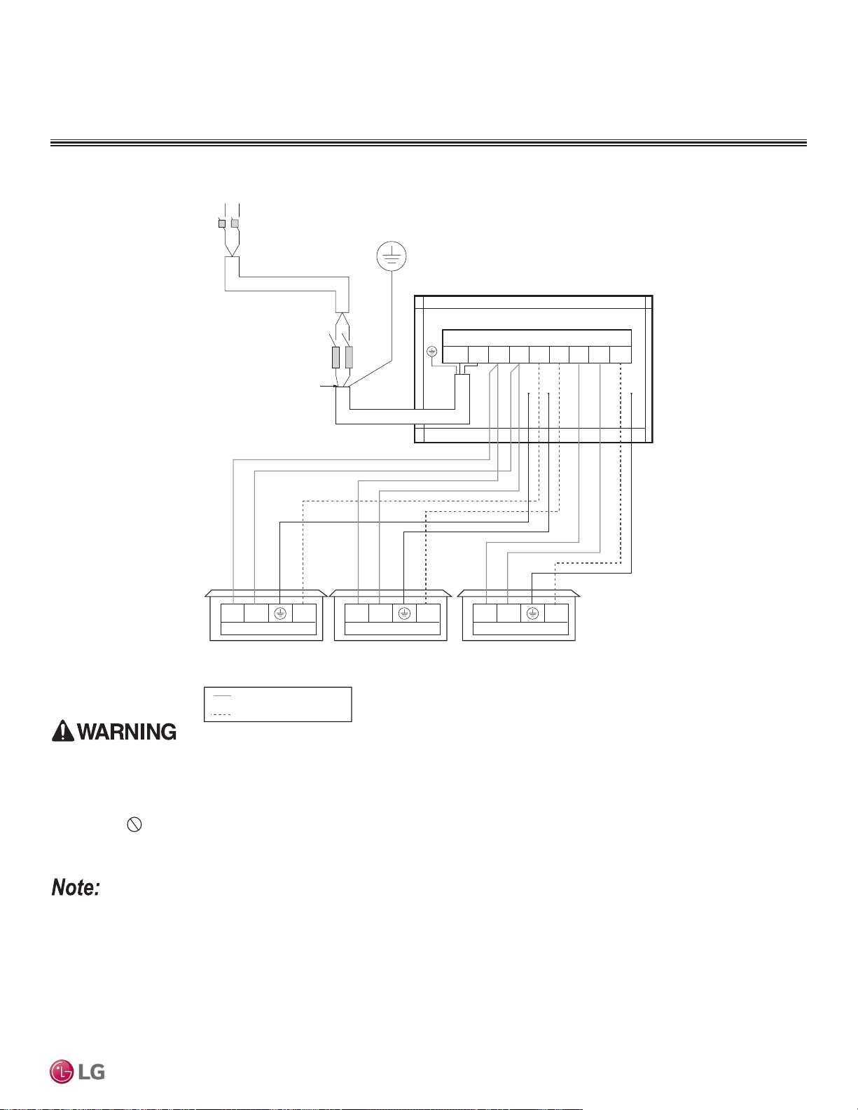
Power Wiring (208-230V) and Communications Cable Details
Figure 290:Multi F LMU24CHV System Power Wiring and Communications Cable.
Outdoor Unit
L1 L2 1(L1) 2(L2) 2(L2)3(A) 3(C)3(B) 1(L1)
Outdoor Unit Terminal Block
L1
L1
L2
L2
G
Power Supply
Main Switch
Circuit Breaker
Fuse
Three-wire Power Wiring
(Including Ground)
COMMUNICATIONS CABLE
POWER WIRING
1(L1) 2(L2)
Indoor Unit Terminal Block
Unit A Unit BUnit C
3
1(L1) 2(L2) 3 1(L1) 2(L2) 3
Indoor Unit Terminal Block Indoor Unit Terminal Block
G
ELECTRICAL CONNECTIONS
• All eld-supplied wiring, components, and materials must follow national, state, and local codes and requirements. Electric shock can cause physical
injury or death.
• Use only stranded, shielded or unshielded copper communications / power wiring from the outdoor unit to the indoor units. If shielded, wiring must be
grounded to the chassis at the outdoor unit only. Improper wiring will result in re, electric shock, physical injury or death.
• Ground wiring is required to prevent accidental electrical shock during current leakage, communication problems from electrical noise, and motor cur-
rent leakage. Do not connect the ground line to the pipes. Improper wiring will result in re, electric shock, physical injury or death.
• Install a main shutoff switch or circuit breaker that interrupts all power sources simultaneously. Electric shock can cause physical injury or death.
• Wiring cable size must comply with applicable national, state, and local codes. Improper wiring will result in re, electric shock, physical injury or death.
• For Multi F with LGRED, refer to Multi F & Multi F MAX with LGRED ODU engineering manual.
• Ground wiring is required to prevent communication problems from electrical noise, and motor current leakage. Failure to provide proper ground wiring
can result in property damage and equipment malfunction.
• All eld-supplied wiring, components, and materials must follow national, state, and local codes and requirements. Failure to install proper electrical
components can result in property damage and equipment malfunction.
• Use only stranded, shielded or unshielded copper communications / power wiring from the outdoor unit to the indoor units. If shielded, wiring must be
grounded to the chassis at the outdoor unit only. Failure to install proper wiring can result in property damage and equipment malfunction.
• Install a main shutoff switch or circuit breaker that interrupts all power sources simultaneously. Failure to install proper electric components can result in
property damage and equipment malfunction.
• Wiring cable size must comply with applicable national, state, and local codes. Improper wiring can result in property damage and equipment malfunction.
Due to our policy of continuous product innovation, some specications may change without notication.
©LG Electronics U.S.A., Inc., Englewood Cliffs, NJ. All rights reserved. “LG” is a registered trademark of LG Corp.
WIRING CONNECTIONS | 231
Wiring Connections
MULTI
F
MAX
MULTI
F
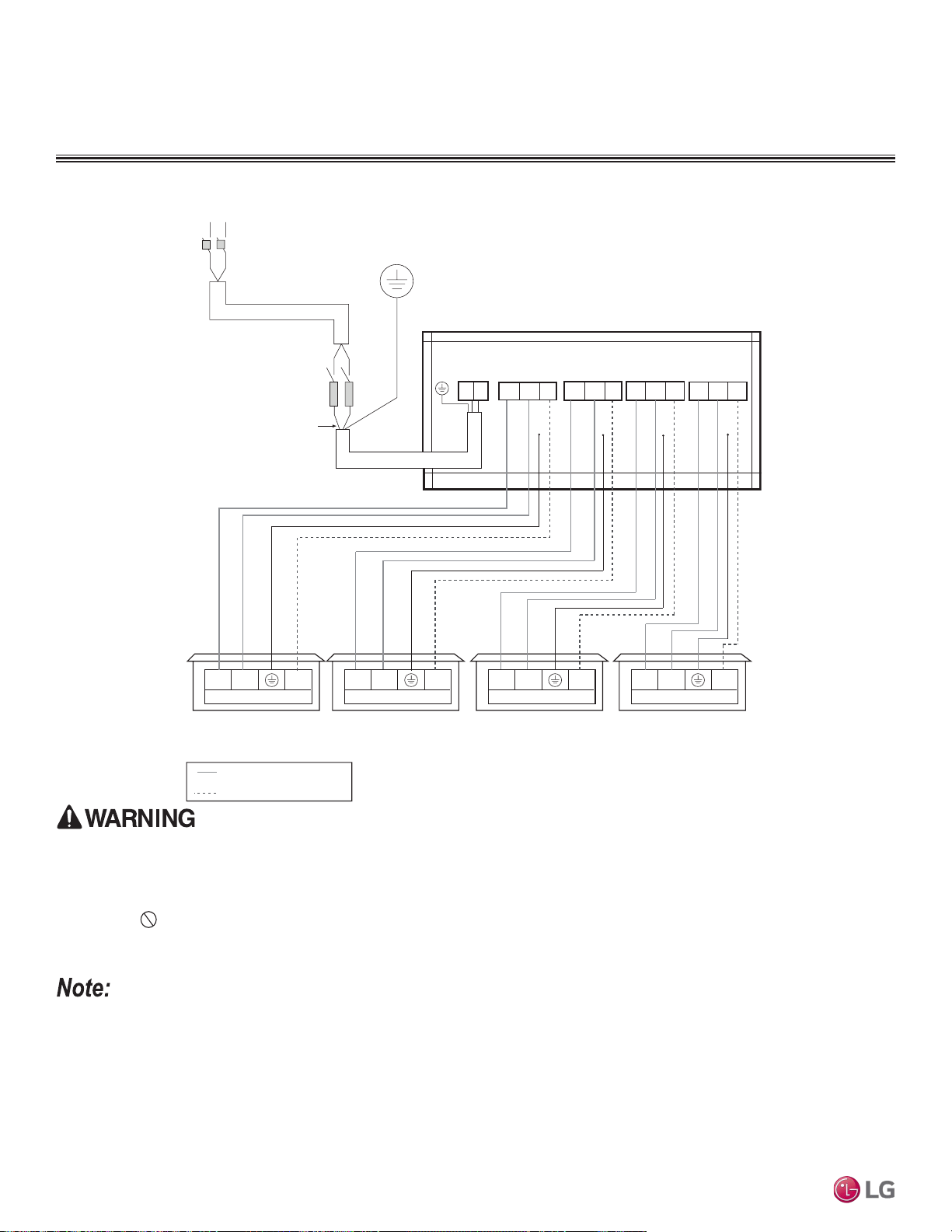
Outdoor Unit
L1 L2 1(L1) 2(L2) 3(A)
3(C)
3(D)
3(B)
Outdoor Unit Terminal Block
L1
L1
L2
L2
G
Power Supply
Main Switch
Circuit Breaker
Fuse
Three-wire Power Wiring
(Including Ground)
COMMUNICATIONS CABLE
POWER WIRING
1(L1) 2(L2)
Indoor Unit Terminal Block
Unit AUnit BUnit CUnit D
3
1(L1) 2(L2) 3 1(L1) 2(L2) 3 1(L1) 2(L2) 3
Indoor Unit Terminal Block Indoor Unit Terminal Block
Indoor Unit Terminal Block
G
1(L1) 2(L2)
2(L2)
1(L1)
2(L2)
1(L1)
Figure 291:Multi F LMU30CHV and LMU36CHV System Power Wiring and Communications Cable.
Power Wiring (208-230V) and Communications Cable Details
ELECTRICAL CONNECTIONS
• All eld-supplied wiring, components, and materials must follow national, state, and local codes and requirements. Electric shock can cause physical
injury or death.
• Use only stranded, shielded or unshielded copper communications / power wiring from the outdoor unit to the indoor units. If shielded, wiring must be
grounded to the chassis at the outdoor unit only. Improper wiring will result in re, electric shock, physical injury or death.
• Ground wiring is required to prevent accidental electrical shock during current leakage, communication problems from electrical noise, and motor cur-
rent leakage. Do not connect the ground line to the pipes. Improper wiring will result in re, electric shock, physical injury or death.
• Install a main shutoff switch or circuit breaker that interrupts all power sources simultaneously. Electric shock can cause physical injury or death.
• Wiring cable size must comply with applicable national, state, and local codes. Improper wiring will result in re, electric shock, physical injury or death.
• For Multi F with LGRED, refer to Multi F & Multi F MAX with LGRED ODU engineering manual.
• Ground wiring is required to prevent communication problems from electrical noise, and motor current leakage. Failure to provide proper ground wiring
can result in property damage and equipment malfunction.
• All eld-supplied wiring, components, and materials must follow national, state, and local codes and requirements. Failure to install proper electrical
components can result in property damage and equipment malfunction.
• Use only stranded, shielded or unshielded copper communications / power wiring from the outdoor unit to the indoor units. If shielded, wiring must be
grounded to the chassis at the outdoor unit only. Failure to install proper wiring can result in property damage and equipment malfunction.
• Install a main shutoff switch or circuit breaker that interrupts all power sources simultaneously. Failure to install proper electric components can result in
property damage and equipment malfunction.
• Wiring cable size must comply with applicable national, state, and local codes. Improper wiring can result in property damage and equipment malfunction.
Due to our policy of continuous product innovation, some specications may change without notication.
©LG Electronics U.S.A., Inc., Englewood Cliffs, NJ. All rights reserved. “LG” is a registered trademark of LG Corp.
232 | WIRING CONNECTIONS
Multi F and Multi F MAX Indoor Unit Engineering Manual
MULTI
F
MAX
MULTI
F
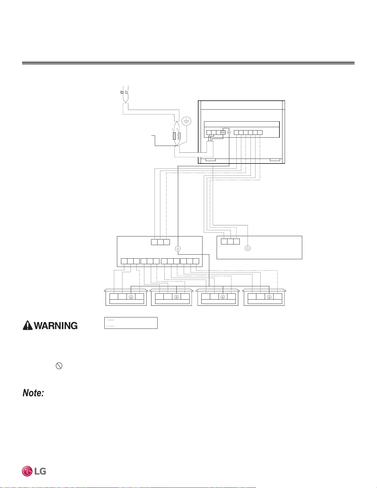
Power Wiring (208-230V) and Communications Cable Details
1(L1) 2(L2)
1(L1) 2(L2) 1(L1) 2(L2) 1(L1) 2(L2) 1(L1) 2(L2)
1(L1) 2(L2)
S
S S S S
1(L1) 2(L2) 1(L1) 2(L2) 1(L1) 2(L2) 1(L1) 2(L2)
Indoor Unit Terminal Block
3 3
Outdoor Unit Terminal Block
L
L
N
N
G
Power Supply
Outdoor unit
Main Switch
Circuit Breaker
Three-wire Power Wiring
(Including Ground)
Fuse
* Same Wiring as Branch Distribution Unit (A)
S
Branch Distribution Unit (B)
3 3
COMMUNICATIONS CABLE
POWER WIRING
L1 L2
1(
L1
)2(
L2
)3(A ) 1(
L1
)2(
L2
)3(B)
Branch Distribution Unit (A)
Indoor Unit Terminal Block Indoor Unit Terminal Block Indoor Unit Terminal Block
Figure 292:Multi F MAX LMU480HV and LMU540HV System Power Wiring and Communications Cable.
ELECTRICAL CONNECTIONS
• All eld-supplied wiring, components, and materials must follow national, state, and local codes and requirements. Electric shock can cause physical
injury or death.
• Use only stranded, shielded or unshielded copper communications / power wiring from the outdoor unit to the indoor units. If shielded, wiring must be
grounded to the chassis at the outdoor unit only. Improper wiring will result in re, electric shock, physical injury or death.
• Ground wiring is required to prevent accidental electrical shock during current leakage, communication problems from electrical noise, and motor cur-
rent leakage. Do not connect the ground line to the pipes. Improper wiring will result in re, electric shock, physical injury or death.
• Install a main shutoff switch or circuit breaker that interrupts all power sources simultaneously. Electric shock can cause physical injury or death.
• Wiring cable size must comply with applicable national, state, and local codes. Improper wiring will result in re, electric shock, physical injury or death.
• For Multi F MAX with LGRED, refer to Multi F & Multi F MAX with LGRED ODU engineering manual.
• Ground wiring is required to prevent communication problems from electrical noise, and motor current leakage. Failure to provide proper ground wiring
can result in property damage and equipment malfunction.
• All eld-supplied wiring, components, and materials must follow national, state, and local codes and requirements. Failure to install proper electrical
components can result in property damage and equipment malfunction.
• Use only stranded, shielded or unshielded copper communications / power wiring from the outdoor unit to the indoor units. If shielded, wiring must be
grounded to the chassis at the outdoor unit only. Failure to install proper wiring can result in property damage and equipment malfunction.
• Install a main shutoff switch or circuit breaker that interrupts all power sources simultaneously. Failure to install proper electric components can result in
property damage and equipment malfunction.
• Wiring cable size must comply with applicable national, state, and local codes. Improper wiring can result in property damage and equipment malfunction.
Due to our policy of continuous product innovation, some specications may change without notication.
©LG Electronics U.S.A., Inc., Englewood Cliffs, NJ. All rights reserved. “LG” is a registered trademark of LG Corp.
WIRING CONNECTIONS | 233
Wiring Connections
MULTI
F
MAX
MULTI
F
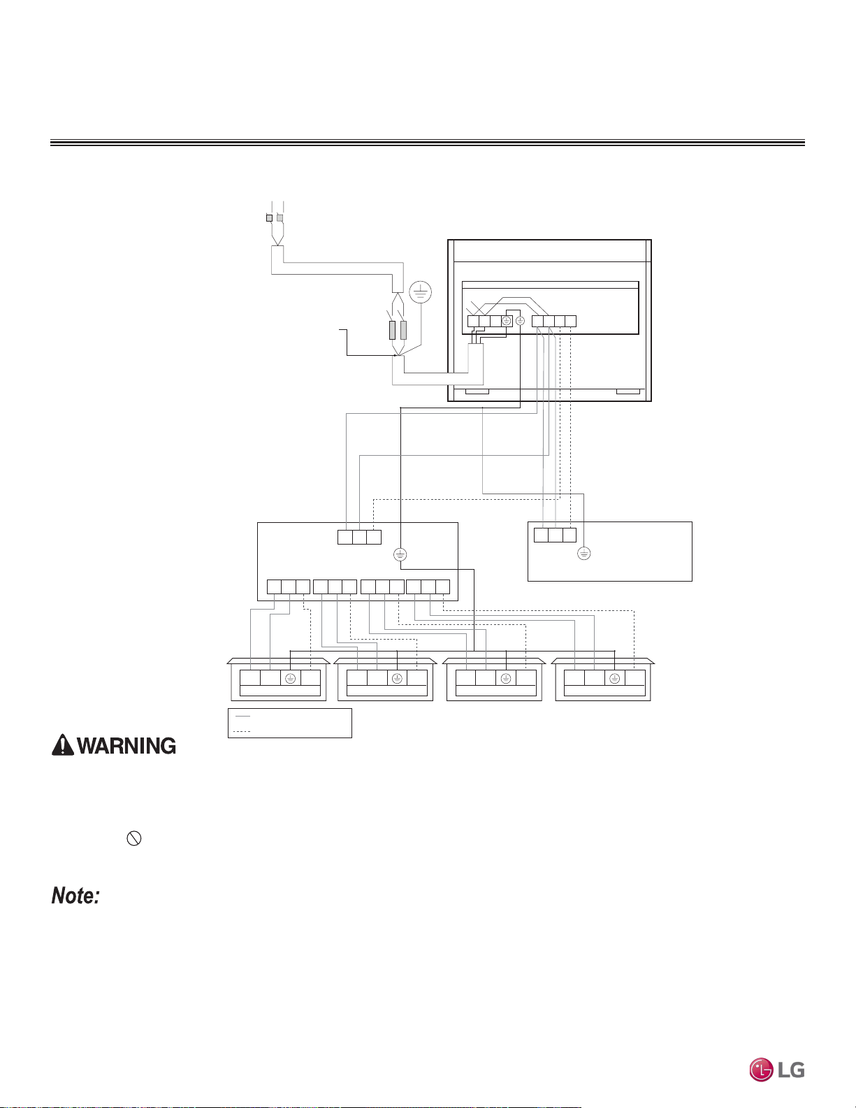
Figure 293:Multi F MAX LMU600HV System Power Wiring and Communications Cable.
Power Wiring (208-230V) and Communications Cable Details
ELECTRICAL CONNECTIONS
• All eld-supplied wiring, components, and materials must follow national, state, and local codes and requirements. Electric shock can cause physical
injury or death.
• Use only stranded, shielded or unshielded copper communications / power wiring from the outdoor unit to the indoor units. If shielded, wiring must be
grounded to the chassis at the outdoor unit only. Improper wiring will result in re, electric shock, physical injury or death.
• Ground wiring is required to prevent accidental electrical shock during current leakage, communication problems from electrical noise, and motor cur-
rent leakage. Do not connect the ground line to the pipes. Improper wiring will result in re, electric shock, physical injury or death.
• Install a main shutoff switch or circuit breaker that interrupts all power sources simultaneously. Electric shock can cause physical injury or death.
• Wiring cable size must comply with applicable national, state, and local codes. Improper wiring will result in re, electric shock, physical injury or death.
• For Multi F MAX with LGRED, refer to Multi F & Multi F MAX with LGRED ODU engineering manual.
• Ground wiring is required to prevent communication problems from electrical noise, and motor current leakage. Failure to provide proper ground wiring
can result in property damage and equipment malfunction.
• All eld-supplied wiring, components, and materials must follow national, state, and local codes and requirements. Failure to install proper electrical
components can result in property damage and equipment malfunction.
• Use only stranded, shielded or unshielded copper communications / power wiring from the outdoor unit to the indoor units. If shielded, wiring must be
grounded to the chassis at the outdoor unit only. Failure to install proper wiring can result in property damage and equipment malfunction.
• Install a main shutoff switch or circuit breaker that interrupts all power sources simultaneously. Failure to install proper electric components can result in
property damage and equipment malfunction.
• Wiring cable size must comply with applicable national, state, and local codes. Improper wiring can result in property damage and equipment malfunction.
1(L1) 2(L2)
1(L1) 2(L2) 1(L1) 2(L2) 1(L1) 2(L2) 1(L1) 2(L2)
1(L1) 2(L2)
S
S S S S
1(L1) 2(L2) 1(L1) 2(L2) 1(L1) 2(L2) 1(L1) 2(L2)
Indoor Unit Terminal Block
3 3
Outdoor Unit Terminal Block
L
L
N
N
G
Power Supply
Outdoor unit
Main Switch
Circuit Breaker
Three-wire Power Wiring
(Including Ground)
Fuse
* Same Wiring as Branch Distribution Unit (A)
S
Branch Distribution Unit (B)
3 3
COMMUNICATIONS CABLE
POWER WIRING
L1 L2
1(
L1
)2(
L2
)3(A ) 3 (B)
Branch Distribution Unit (A)
Indoor Unit Terminal Block Indoor Unit Terminal Block Indoor Unit Terminal Block
Due to our policy of continuous product innovation, some specications may change without notication.
©LG Electronics U.S.A., Inc., Englewood Cliffs, NJ. All rights reserved. “LG” is a registered trademark of LG Corp.
234 | WIRING CONNECTIONS
Multi F and Multi F MAX Indoor Unit Engineering Manual
MULTI
F
MAX
MULTI
F
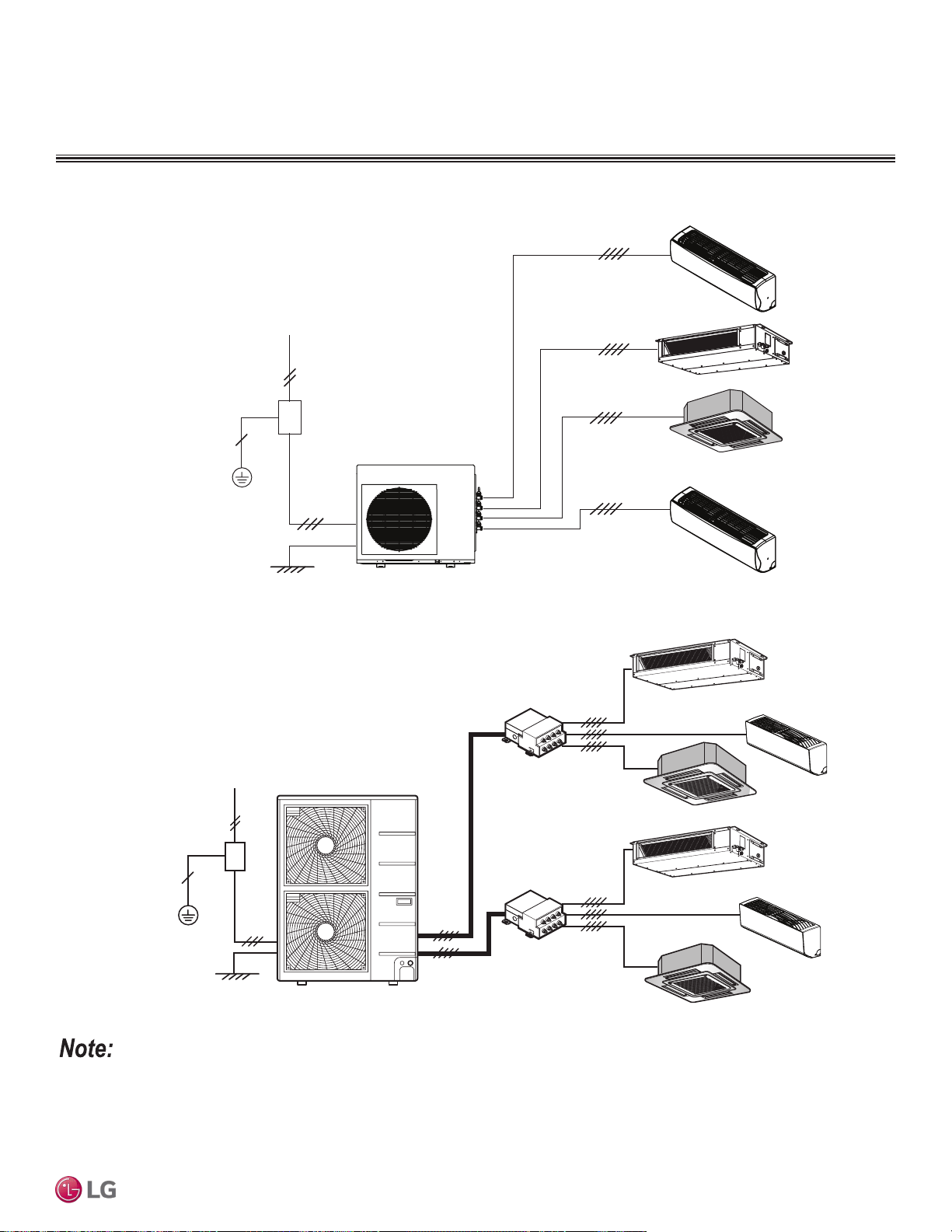
Power Wiring (208-230V) and Communications Cable Details
ELECTRICAL CONNECTIONS
Figure 294:Multi F with LGRED System General Power / Communications System Schematic.
Figure 295:Multi F MAX with LGRED System General Power / Communications System Schematic.
• Secure the separate wires in the control box panel using zip ties.
• Secure wiring with accessory clamps so that it does not touch the piping.
• Use a conduit for the communications cable / power wiring from the outdoor unit to the indoor / branch distribution units.
• Make sure the communications cable / power wiring from the outdoor units to the indoor / branch distribution units, and the power wiring to the
outdoor unit are separate, otherwise, the outdoor unit operation will be affected by electrical noise and will malfunction or fail.
Power Supply
Circuit Breaker
Indoor Unit
Branch Distribution Unit
Ground Wiring
Outdoor Unit
Branch Distribution Unit
Indoor Units
Power Supply
Circuit Breaker
Ground Wiring
Outdoor Unit
Due to our policy of continuous product innovation, some specications may change without notication.
©LG Electronics U.S.A., Inc., Englewood Cliffs, NJ. All rights reserved. “LG” is a registered trademark of LG Corp.
WIRING CONNECTIONS | 235
Wiring Connections
MULTI
F
MAX
MULTI
F
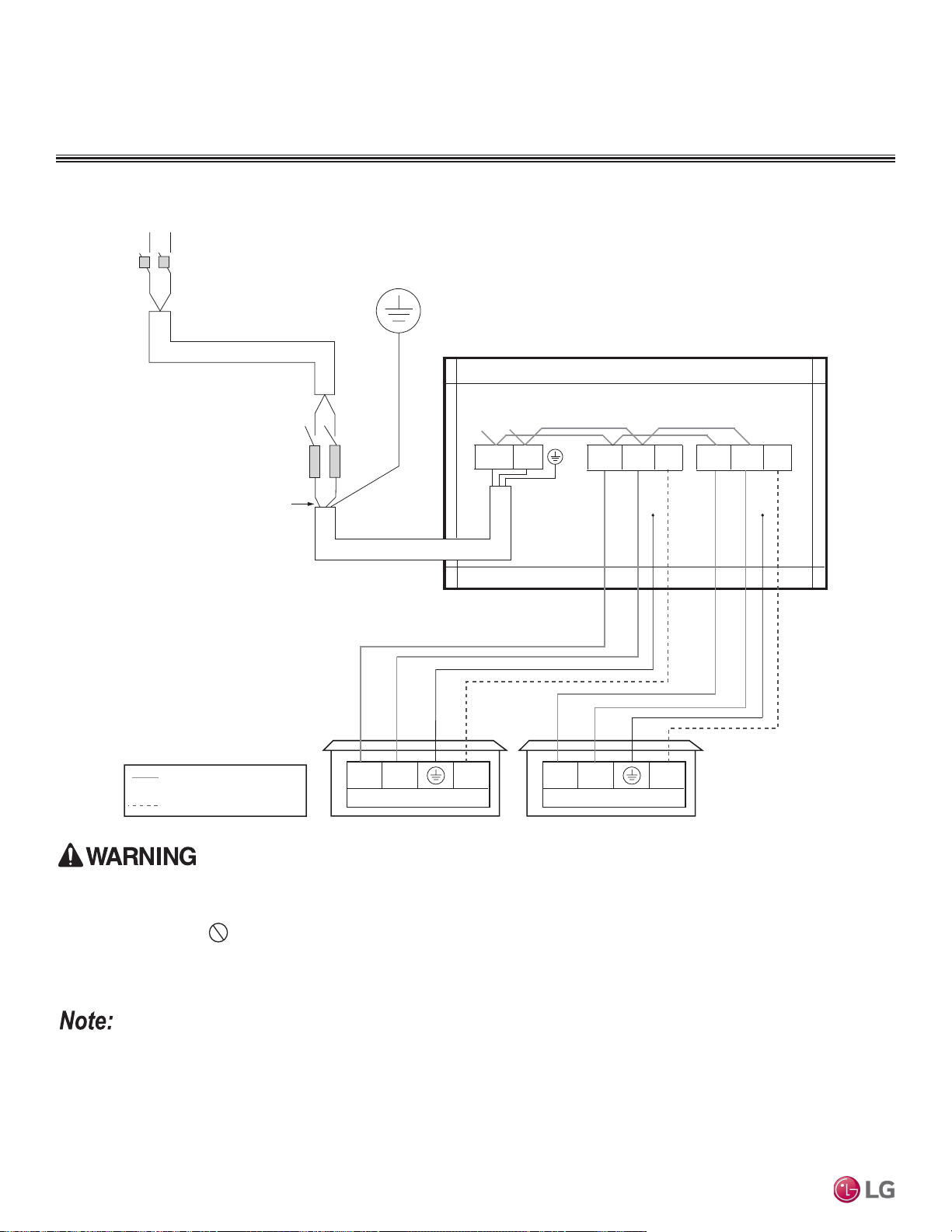
Power Wiring (208-230V) and Communications Cable Details
ELECTRICAL CONNECTIONS
Figure 296:Multi F with LGRED LMU180HHV System Power Wiring and Communications Cable Connections.
Outdoor Unit
L1 L2 3(A)
Outdoor Unit Terminal Block
L1
L1
L2
L2
G
Power Supply
Main Switch
Circuit Breaker
Fuse
Three-wire Power Wiring
(Including Ground)
COMMUNICATION CABLE
POWER WIRING
1(L1) 2(L2)
Indoor Unit Terminal Block
Unit A Unit B
3
1(L1) 2(L2) 3
Indoor Unit Terminal Block
G
1(L1) 2(L2)
G G
3(B)1(L1) 2(L2)
• All field-supplied wiring, components, sizes, and materials must comply with all applicable national, state, and local codes and requirements.
Improper wiring will result in fire, electric shock, physical injury or death.
• Ground wiring is required to prevent accidental electrical shock during current leakage, communication problems from electrical noise, and
motor current leakage. Do not connect the ground line to the pipes. There is a risk of fire, electric shock, explosion, physical injury or
death.
• Install a main shutoff switch or circuit breaker that interrupts all power sources simultaneously. There is a risk of fire, electric shock, explosion,
physical injury or death.
• All field-supplied wiring, components, sizes, and materials must comply with all applicable national, state, and local codes and requirements.
Failure to install proper electrical components can result in property damage and equipment malfunction.
• Ground wiring is required to prevent communication problems from electrical noise, and motor current leakage. Failure to provide proper
ground wiring can result in property damage and equipment malfunction.
• Install a main shutoff switch or circuit breaker that interrupts all power sources simultaneously. Failure to install proper electric components
will result in property damage and equipment malfunction.
• Maintain polarity throughout the communication network. The system will malfunction if not properly wired.
Due to our policy of continuous product innovation, some specications may change without notication.
©LG Electronics U.S.A., Inc., Englewood Cliffs, NJ. All rights reserved. “LG” is a registered trademark of LG Corp.
236 | WIRING CONNECTIONS
Multi F and Multi F MAX Indoor Unit Engineering Manual
MULTI
F
MAX
MULTI
F
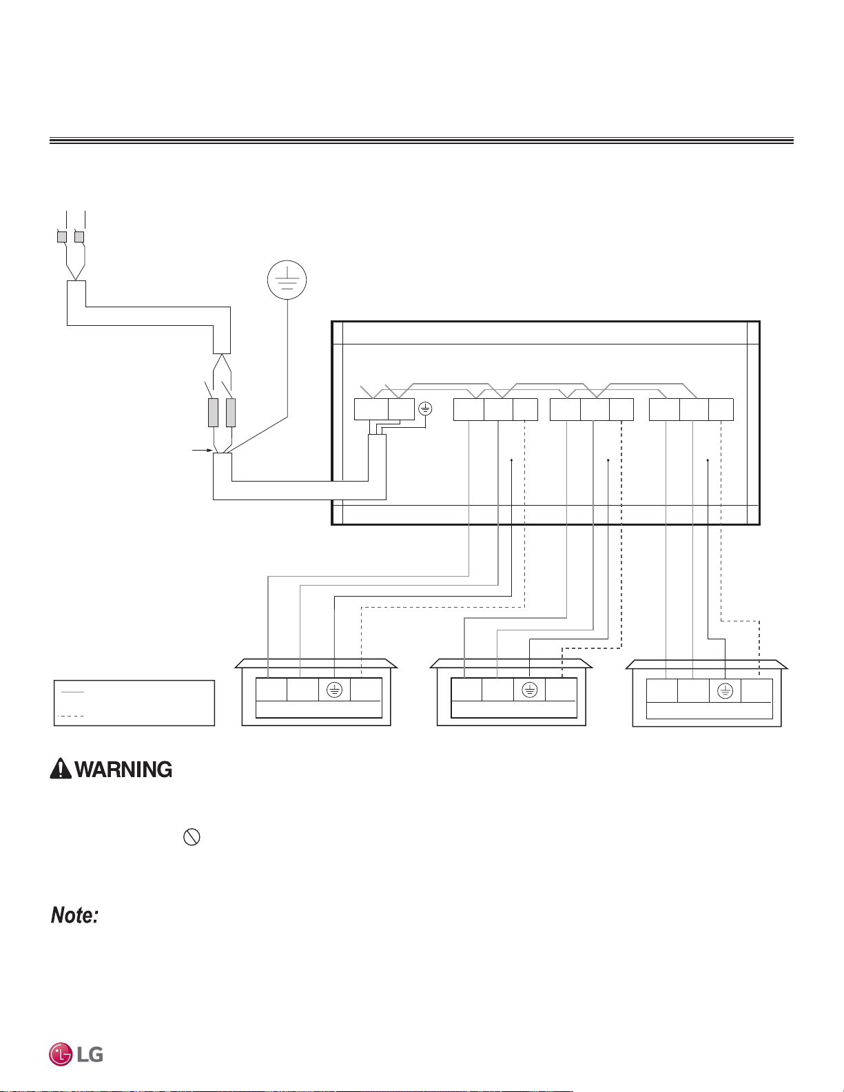
Power Wiring (208-230V) and Communications Cable Details
ELECTRICAL CONNECTIONS
Figure 297:Multi F with LGRED LMU240HHV System Power Wiring and Communications Cable Connections.
Outdoor Unit
L1 L2 3(A)
Outdoor Unit Terminal Block
L1
L2
G
Circuit Breaker
Fuse
Three-wire Power Wiring
(Including Ground)
COMMUNICATION CABLE
POWER WIRING
1(L1) 2(L2)
Indoor Unit Terminal Block
Unit A Unit B
3
1(L1) 2(L2) 3
Indoor Unit Terminal Block
G
1(L1) 2(L2)
G G
3(B)1(L1) 2(L2)
G
3(C)1(L1) 2(L2)
Unit C
1(L1) 2(L2) 3
Indoor Unit Terminal Block
L1 L2
Power Supply
Main Switch
• All field-supplied wiring, components, sizes, and materials must comply with all applicable national, state, and local codes and requirements.
Improper wiring will result in fire, electric shock, physical injury or death.
• Ground wiring is required to prevent accidental electrical shock during current leakage, communication problems from electrical noise, and
motor current leakage. Do not connect the ground line to the pipes. There is a risk of fire, electric shock, explosion, physical injury or
death.
• Install a main shutoff switch or circuit breaker that interrupts all power sources simultaneously. There is a risk of fire, electric shock, explosion,
physical injury or death.
• All field-supplied wiring, components, sizes, and materials must comply with all applicable national, state, and local codes and requirements.
Failure to install proper electrical components can result in property damage and equipment malfunction.
• Ground wiring is required to prevent communication problems from electrical noise, and motor current leakage. Failure to provide proper
ground wiring can result in property damage and equipment malfunction.
• Install a main shutoff switch or circuit breaker that interrupts all power sources simultaneously. Failure to install proper electric components
will result in property damage and equipment malfunction.
• Maintain polarity throughout the communication network. The system will malfunction if not properly wired.
Due to our policy of continuous product innovation, some specications may change without notication.
©LG Electronics U.S.A., Inc., Englewood Cliffs, NJ. All rights reserved. “LG” is a registered trademark of LG Corp.
WIRING CONNECTIONS | 237
Wiring Connections
MULTI
F
MAX
MULTI
F
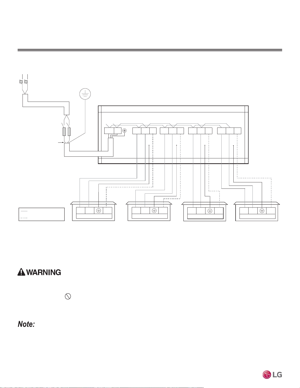
Power Wiring (208-230V) and Communications Cable Details
ELECTRICAL CONNECTIONS
Figure 298:Multi F with LGRED LMU300HHV System Power Wiring and Communications Cable Connections.
Outdoor Unit
L1 L2 3(A)
Outdoor Unit Terminal Block
L1
L2
G
Circuit Breaker
Fuse
Three-wire Power Wiring
(Including Ground)
COMMUNICATION CABLE
POWER WIRING
1(L1) 2(L2)
Indoor Unit Terminal Block
Unit A Unit B
3
1(L1) 2(L2) 3
Indoor Unit Terminal Block
G
1(L1) 2(L2)
G G
3(B)1(L1) 2(L2)
G
3(C)1(L1) 2(L2)
Unit C
1(L1) 2(L2) 3
Indoor Unit Terminal Block
L1 L2
Power Supply
Main Switch
G
3(D)1(L1) 2(L2)
Unit D
1(L1) 2(L2) 3
Indoor Unit Terminal Block
• All field-supplied wiring, components, sizes, and materials must comply with all applicable national, state, and local codes and requirements.
Improper wiring will result in fire, electric shock, physical injury or death.
• Ground wiring is required to prevent accidental electrical shock during current leakage, communication problems from electrical noise, and
motor current leakage. Do not connect the ground line to the pipes. There is a risk of fire, electric shock, explosion, physical injury or
death.
• Install a main shutoff switch or circuit breaker that interrupts all power sources simultaneously. There is a risk of fire, electric shock, explosion,
physical injury or death.
• All field-supplied wiring, components, sizes, and materials must comply with all applicable national, state, and local codes and requirements.
Failure to install proper electrical components can result in property damage and equipment malfunction.
• Ground wiring is required to prevent communication problems from electrical noise, and motor current leakage. Failure to provide proper
ground wiring can result in property damage and equipment malfunction.
• Install a main shutoff switch or circuit breaker that interrupts all power sources simultaneously. Failure to install proper electric components
will result in property damage and equipment malfunction.
• Maintain polarity throughout the communication network. The system will malfunction if not properly wired.
Due to our policy of continuous product innovation, some specications may change without notication.
©LG Electronics U.S.A., Inc., Englewood Cliffs, NJ. All rights reserved. “LG” is a registered trademark of LG Corp.
238 | WIRING CONNECTIONS
Multi F and Multi F MAX Indoor Unit Engineering Manual
MULTI
F
MAX
MULTI
F
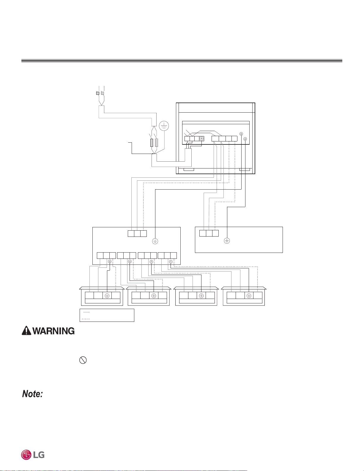
Power Wiring (208-230V) and Communications Cable Details
ELECTRICAL CONNECTIONS
Figure 299:Multi F MAX with LGRED LMU360HHV and LMU420HHV System Power Wiring and Communications Cable Connections.
1(L1) 2(L2)
1(L1) 2(L2) 1(L1) 2(L2) 1(L1) 2(L2) 1(L1) 2(L2)
1(L1) 2(L2)
S
S S S S
1(L1) 2(L2) 1(L1) 2(L2) 1(L1) 2(L2) 1(L1) 2(L2)
Indoor Unit Terminal Block
3 3
Outdoor Unit Terminal Block
L
L
N
N
G
Power Supply
Outdoor Unit
Main Switch
Circuit Breaker
Three-wire Power Wiring
(Including Ground)
Fuse
* Same Wiring as Branch Distribution Unit (A)
S
Branch Distribution Unit (B)
3 3
COMMUNICATIONS CABLE
POWER WIRING
L1 L2
Branch Distribution Unit (A)
Indoor Unit Terminal Block Indoor Unit Terminal Block Indoor Unit Terminal Block
3(A)1(L1) 2(L2)
3(B)
• All field-supplied wiring, components, sizes, and materials must comply with all applicable national, state, and local codes and requirements.
Improper wiring will result in fire, electric shock, physical injury or death.
• Ground wiring is required to prevent accidental electrical shock during current leakage, communication problems from electrical noise, and
motor current leakage. Do not connect the ground line to the pipes. There is a risk of fire, electric shock, explosion, physical injury or
death.
• Install a main shutoff switch or circuit breaker that interrupts all power sources simultaneously. There is a risk of fire, electric shock, explosion,
physical injury or death.
• All field-supplied wiring, components, sizes, and materials must comply with all applicable national, state, and local codes and requirements.
Failure to install proper electrical components can result in property damage and equipment malfunction.
• Ground wiring is required to prevent communication problems from electrical noise, and motor current leakage. Failure to provide proper
ground wiring can result in property damage and equipment malfunction.
• Install a main shutoff switch or circuit breaker that interrupts all power sources simultaneously. Failure to install proper electric components
will result in property damage and equipment malfunction.
• Maintain polarity throughout the communication network. The system will malfunction if not properly wired.
Due to our policy of continuous product innovation, some specications may change without notication.
©LG Electronics U.S.A., Inc., Englewood Cliffs, NJ. All rights reserved. “LG” is a registered trademark of LG Corp.
WIRING CONNECTIONS | 239
Wiring Connections
MULTI
F
MAX
MULTI
F
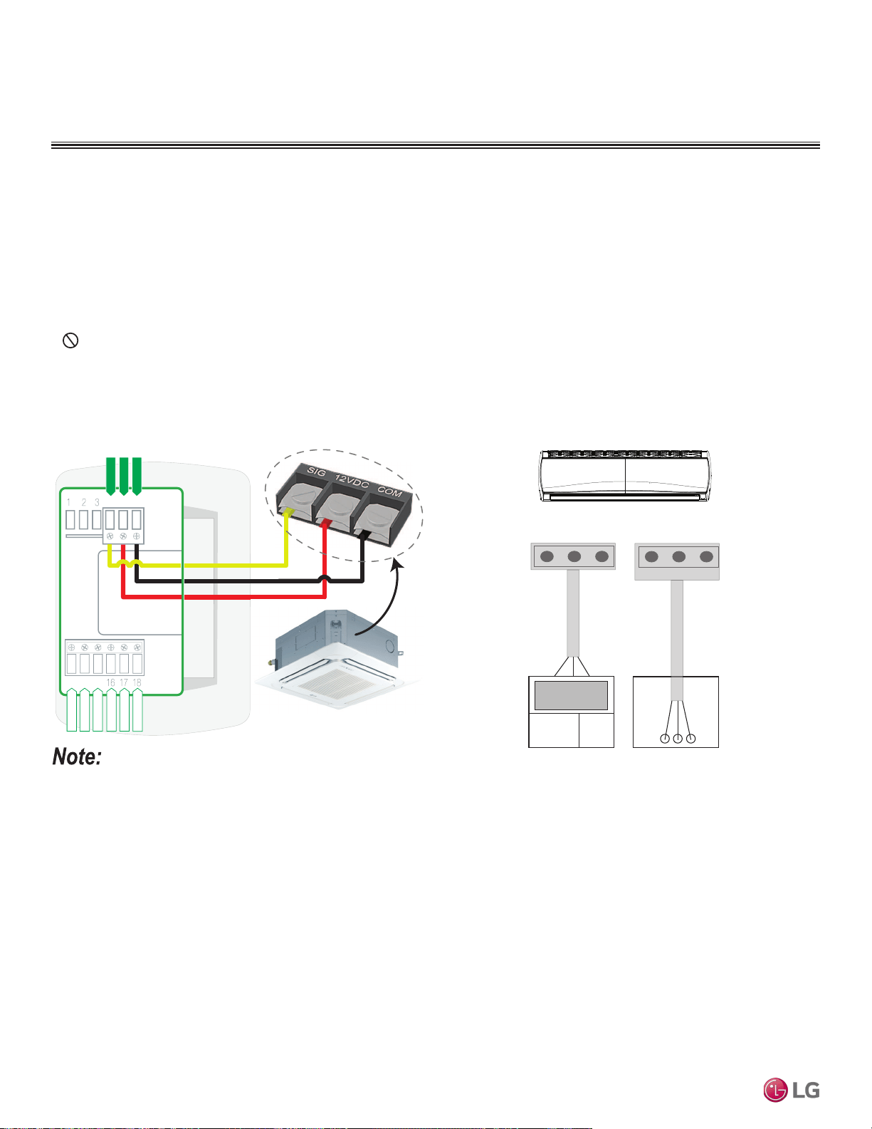
From Indoor Units to Remote Controllers
• Communication cable from indoor unit to remote controller(s) is to be field provided or LG provided 22 AWG, 3-conductor, twisted, stranded,
unshielded. Wiring must comply with all applicable local and national codes.
• If using the LG Controller / Extension cable and the length needs to be further extended, the LG Extension Kit (sold separately) must be
used. A maximum of four (4) kits (up to 165 feet) can be used.
• Remote controllers have hardwired connections: SIG - 12V - GND (Comm.) terminals.
• Indoor unit controller connections depend on type of indoor unit being installed. Some indoor units use terminal block connections; other
indoor units use Molex connections. See diagrams below for the two options. Refer to the wiring diagram schematic found in the indoor unit
itself, or to the indoor unit wiring diagrams in the Engineering Manuals for more information.
• NEVER splice, cut, or extend LG provided cable with field provided cable. Always include enough cable to cover distance between the
indoor unit and the remote controller.
• Set the indoor unit operating parameters using DIP switches, or by setting up the remote controller. Refer to the indoor unit installation
manuals for more details.
Cable connected to Zone Controller is the factory default connection.
Figure 300:One Example of Indoor Unit to Zone Controller Connection.
BACnet+
BACnet-
BACnet Common
Not used
Not used
Not used
Common
4 5 6
13 14 15
Typical Indoor Unit
Signal
12VDC
YL
RD
BK
CN-REMO
Indoor Unit
RD
BK
YL
Front
CN-REMO
RDBKYL
Back
Figure 301:Another Example of Indoor Unit to Zone Controller
Connection.
Remote Controller Connections
ELECTRICAL CONNECTIONS
Due to our policy of continuous product innovation, some specications may change without notication.
©LG Electronics U.S.A., Inc., Englewood Cliffs, NJ. All rights reserved. “LG” is a registered trademark of LG Corp.
240 | WIRING CONNECTIONS
Multi F and Multi F MAX Indoor Unit Engineering Manual
MULTI
F
MAX
MULTI
F
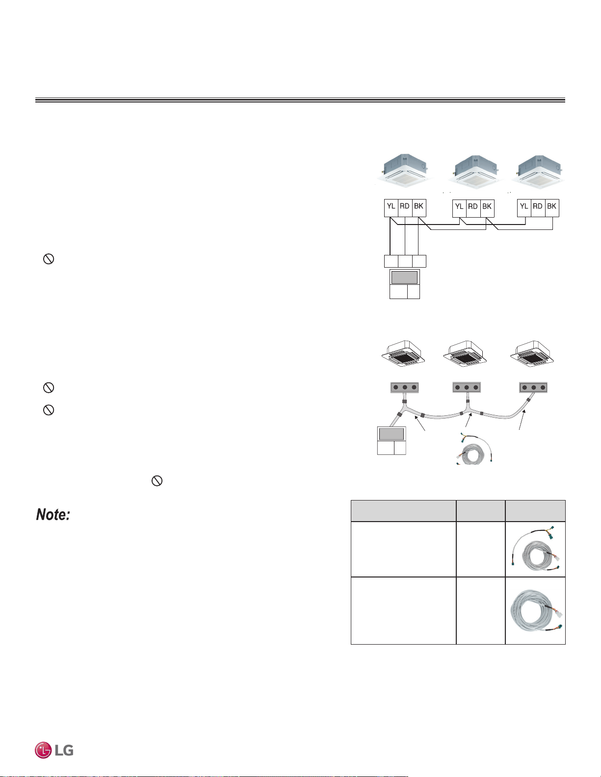
Indoor Unit Group Control
ELECTRICAL CONNECTIONS
Between Multiple Indoor Units Operating as a
Group (Group Control)
If any indoor units were specified to operate in unison:
• Before running the field provided or LG provided cable, decide which indoor unit will be
the “Master.” The other indoor units in that group will be designated as “Slave(s).” The
zone controller will be connected to the “Master.”
• Set the pertinent DIP switch at each indoor unit to identify the Master and Slave(s).
On wall mounted indoor unit models, set the assignment using the handheld remote
controller.
• Use a daisy chain configuration and connect all of the group’s indoor units together
starting at the “Master” unit.
• NEVER splice, cut, or extend LG provided cable with field provided cable. Always
include enough cable to cover distance between all components.
For indoor units with hardwired connections SIG - 12V - GND (Comm.)
terminals:
• From the controller to the master indoor unit, use field provided or LG provided 22
AWG, 3-conductor, twisted, stranded, unshielded. All wiring must comply with all ap-
plicable local / national codes.
• From the master indoor unit to the slave indoor unit(s), daisy chain using field provided
or LG provided 22 AWG, 3-conductor, twisted, stranded, unshielded. All wiring must
comply with all applicable local / national codes.
• Do not attach wire to 12VDC terminal to the slave indoor units. All wiring must
comply with all applicable local and national codes.
• NEVER splice, cut, or extend LG provided cable with field provided cable. Always
include enough cable to cover distance between all components.
For indoor units with CN-REMO connections:
Use one (or multiple) Group Control Kit(s) (sold separately) containing extension and
Y-splitter cables. Use one (1) group control cable kit for each indoor unit in the group
except for the last indoor unit. NEVER splice, cut, or extend cable length with field
provided cable.
• Cable connected to zone controller is the factory default connection.
• Indoor unit connections depend on indoor unit type.
Figure 302:Example of Indoor Unit Group to Zone
Controller Connections (Sig-12V-GND [Comm.]
Terminal).
Figure 303:Example of Indoor Unit Group to Zone
Controller Connections (CN-REMO).
Master Indoor Unit
Indoor Unit
Indoor Unit
Signal
12VDC Comm.
Signal
12VDC Comm.
4 5
6
Signal
12VDC Comm.
Signal
12VDC Comm.
CN-REMO
On All Indoor Unit Styles
CN-REMO
On All Indoor Unit Styles
CN-REMO
On All Indoor Unit Styles
LG
Supplied
LG Supplied Group Control Kit (PZCWRCG3)
Accessory
Model
Number
Image
Wired Remote Group Control
Cable Assembly -
For connecting multiple
indoor units to a control group
PZCWRCG3
Wired Remote/Wired Remote
Extension Cable -
For extending the distance
between indoor units or
remote controllers in a control
group
PZCWRC1
Table 130:Accessories for Some Group Control Applications.
General Specifications
• Wired remote controllers can be connected to all indoor unit types.
• Wireless controllers can be used in conjunction with wired remote controllers.
• A dry contact unit can be connected with a central controller simultaneously.
- The master indoor unit is recognized by the dry contact unit and the central
controller.
- Group Control only available for indoor units manufactured after February
2009.
- The central controller can control indoor units after setting the address of the
master indoor unit only.
- Slave indoor unit cannot be individually controlled by central controller.
- Slave indoor unit will operate like master indoor unit.
• If an error occurs with the indoor unit, the error will be displayed on the wired remote controller.
• The following functions are available with group control:
• Selection of operation options (operation/mode/set temperature)
• Control of air flow rate (High/Medium/Low)
Due to our policy of continuous product innovation, some specications may change without notication.
©LG Electronics U.S.A., Inc., Englewood Cliffs, NJ. All rights reserved. “LG” is a registered trademark of LG Corp.
WIRING CONNECTIONS | 241
Wiring Connections
MULTI
F
MAX
MULTI
F
ACRONYMS
ABS
Acrylonitrile Butadiene Styrene
IAQ
Indoor Air Quality
AC
Air Conditioner
IDU
Indoor Unit
ACP
Advanced Control Platform
IUCF
Indoor Unit Correction Factor
ARI
Air Conditioning and Refrigeration Institute
KTL
Korea Testing Laboratories
ASHRAE
American Society of Heating, Refrigeration, and
Air Conditioning
LATS
LG Air Conditioning Technical Solution
AWG
American Wire Gauge
LGAP
LG Air Conditioner Protocol
BDU
Branch Distribution (Unit)
MAT
Mixed Air Temperature
Btu/h
British Thermal Units per hour
MBh
Thousands BTUs per hour
CAV
Constant Air Volume
MCA
Maximum Circuit Ampacity
CCR
Corrected Capacity Ratio
MFS
Maximum Fuse Size
CDOA
Coupled Dedicated Outdoor Air
NEC
National Electrical Code
CFM
Cubic Feet per Minute
OAT
Outdoor Air Temperature
CR
Combination Ratio
ODU
Outdoor Unit
DB
Dry Bulb
OUCF
Outdoor Unit Correction Factor
dB(A)
Decibels with “A” frequency weighting
PDI
Power Distribution Indicator
DDOAS
Decoupled Dedicated Outdoor Air
PI
Power Input
DFS
Duct-Free Split
PTAC
Packaged Terminal Air Conditioner
DI
Digital Input
PVE
Polyvinyl Ether
DO
Digital Output
RAT
Return Air Temperature
ECM
Electronically Commutated Motor
RCL
Refrigerant Concentration Limit
EEV
Electronic Expansion Valve
SC
Sensible Capacity
ELF
Equivalent Length in Feet
TC
Total Capacity
EPDM
Ethylene Propylene Diene M-Class Rubber
VAV
Variable Air Volume
ESP
External Static Pressure
VRF
Variable Refrigerant Flow
ETL
Electronic Testing Laboratories
VRP
Ventilation Rate Procedure
HACR
Heating, Air Conditioning, and Refrigeration
H/M/L
High / Medium / Low
Table 131: Table of Acronyms.
Due to our policy of continuous product innovation, some specications may change without notication.
©LG Electronics U.S.A., Inc., Englewood Cliffs, NJ. All rights reserved. “LG” is a registered trademark of LG Corp.
242 | WIRING CONNECTIONS
Multi F and Multi F MAX Indoor Unit Engineering Manual
MULTI
F
MAX
MULTI
F
EM_MultiF_IDU_04_2020
Supersedes: EM_MultiF_IDU_09_19
EM_MultiF_IDU_08_19
EM_MultiF_IDU_11_18
EM_MultiF_IDU_10_17
EM_MultiF_IDU_11_16
EM_MultiF_IDU_7_16
EM_MultiF_IDU_7_15
EM-MultiFIDU-01-15
EM-MultiFIDU-06-14
20001747 ISO 9001: 2008
LG ELECTRONICS INC.
LG Electronics, U.S.A., Inc.
Air Conditioning Technologies
4300 North Point Parkway
Alpharetta, Georgia 30022
www.lghvac.com