Operator's Manual
P R 0 F E S S I 0 N A L
33" SNOW THROWER
Model No. 247.88033
CAUTION: Before using
this product, read this
manual and follow all
safety rules and operating
instructions.
,, SAFETY
* ASSEMBLY
o OPERATION
" MAINTENANCE
PARTS LiST
ESPAI_OL
Sears, Roebuck and Co., Hoffman Estates, IL 60179, U.S.A.
Visit our website: www, craftsrnan.corn FORMNO.789-03348
8/28/2007
WarrantyStatement..................................Page2
SafeOperationPractices.........................Pages3-4
SafetyLabels............................................Page5
Assembly..................................................Pages6-9
Operation..................................................Pages10-13
ServiceandMaintenance.........................Pages14-21
Off-SeasonStorage..................................Page22
TroubleShooting......................................Page23
PartsList...................................................Page24-34
RepairProtectionAgreement...................Page38
Espa_ol.....................................................Page39
ServiceNumbers......................................BackCover
Two =Year Limited Warranty on Craftsman Snow Thrower
Whenassembled,operatedand maintainedaccordingto all suppliedinstructions,if thisCraftsmanproductfailsdueto a defectin materialor
workmanshipwithintwoyearsfromthedate of purchase,returnit toany Searsstore,SearsParts& RepairServiceCenteror otherCraftsman
outletinthe UnitedStatesforfree repair.In-homewarrantyserviceis available,butyou will haveto paya trip charge.
Thiswarrantycoversonly defectsin materialandworkmanship. Sears will NOTpayfor:
• Expendableitemswhich becomewornduring normaluse,suchas skidshoes,shaveplate andsparkplugs.
• Repairsnecessarybecauseof operatornegligence,includingbutnot limitedto,electricalandmechanicaldamagecausedby improper
storage,bentcrankshafts,failureto use theproper gradeand amountof engineoil, orfailureto maintaintheequipmentaccordingto all
instructionscontainedsuppliedwith the product.
• Engine(fuelsystem)cleaningorrepairscausedbyfuel determinedto becontaminatedor oxidized(stale). Ingeneral,fuel shouldbeused
within30 daysof itspurchasedate.
Thiswarrantyappliesforonly 90 daysif this productis everusedfor commercialor rentalpurposes.
This warrantyappliesonly whilethisproductis usedinthe UnitedStates.
This warrantygivesyouspecificlegalrights,andyou mayalsohaveotherrightswhichvaryfromstateto state.
Sears, Roebuckand Co.,HoffmanEstates,IL 60179
EngineOil Type: SAE5W-30
EngineOil Capacity: 28 ounces
FuelCapacity: 4 Quarts
SparkPlug: Champion@RJ19LM
SparkPlugGap: .030"
Model Number.................................................................
Serial Number.................................................................
Dateof Purchase.............................................................
Recordthe modelnumber,serialnumber
anddateof purchaseabove
© Sears Brands,LLC
Thissymbolpointsout importantsafetyinstructions
which,if notfollowed,couldendangerthe personal
safetyand/orpropertyof yourselfandothers.Read
andfollowall instructionsin this manualbefore
attemptingto operatethismachine.Failureto complywiththese
instructionsmay resultin personalinjury.Whenyousee this symbol,
HEEDITSWARNING!
Your Responsibility: Restrictthe useof thispowermachineto
personswho read,understand,and followthe warningsand instruc-
tions inthismanualandonthe machine.
This machinewas builtto beoperatedaccordingto the rulesfor
safeoperationinthis manual.As withanytype of powerequipment,
carelessnessor error on the part of the operatorcan resultin serious
injury.Thismachineis capableof amputatinghandsandfeetand
throwingobjects.Failureto observethefollowingsafetyinstructions
couldresultinseriousinjuryor death.
EngineExhaust,someof its constituents,and certain vehicle
componentscontainor emitchemicalsknownto Stateof Californiato
causecancerand birthdefectsor otherreproductiveharm.
TRAINING
,, Read,understand,andfollowall instructionsonthe machineandin
the manual(s)beforeattemptingto assembleand operate.Keepthis
manualina safe placefor futureand regular referenceandfor ordering
replacementparts.
,, Be familiarwith allcontrolsandtheir properoperation.Knowhowto stop
the machineanddisengagethem quickly.
,, Neverallowchildren under 14years oldto operatethis machine.Chil-
dren 14years old and overshouldreadand understandthe operation
instructionsand safetyrulesin this manualandshouldbetrained and
supervisedbya parent.
,, Neverallowadultsto operatethis machinewithout properinstruction.
• Thrownobjectscan causeseriouspersonalinjury.Plan yoursnow-
throwingpatternto avoiddischargeof materialtoward roads,bystanders
andthe like.
,, Keepbystanders,helpers,pets andchildren at least75 feet fromthe
machinewhile it is in operation.Stop machineif anyoneentersthe area.
,, Exercisecautionto avoidslippingorfalling, especiallywhenoperatingin
reverse.
PREPARATION
Thoroughlyinspectthe area wherethe equipmentis to be used.Removeall
doormats,newspapers,sleds,boards,wires andotherforeignobjects,which
couldbetrippedoverorthrownbythe auger/impeller.
• Alwayswearsafetyglassesor eyeshields duringoperationandwhile
performingan adjustmentor repairto protectyour eyes.Thrown objects
which ricochetcan causeserious injuryto the eyes.
• Donotoperate withoutwearingadequatewinteroutergarments.Donot
wearjewelry, longscarvesor otherlooseclothing,whichcould become
entangledinmoving parts.Wearfootwearwhichwill improvefootingon
slippery surfaces.
• Usea groundedthree-wireextensioncord and receptaclefor all units
with electricstart engines.
• Adjustcollector housingheightto clear gravelor crushedrocksurfaces.
• Disengageall controlleversbeforestartingthe engine.
,, Neverattemptto makeany adjustmentswhileengineis running,except
where specificallyrecommendedinthe operator'smanual.
,, Letengineand machineadjustto outdoortemperaturebefore startingto
clear snow.
Safe Handling of Gasoline
Toavoidpersonalinjuryor propertydamageuseextremecarein handling
gasoline.Gasolineis extremelyflammableand thevaporsare explosive.
Seriouspersonalinjury can occurwhen gasolineis spilled onyourself or your
clothes,whichcan ignite.Washyour skinandchangeclothesimmediately.
,, Useonly an approvedgasolinecontainer.
• Extinguishall cigarettes,cigars,pipesand othersourcesof ignition.
• Neverfuel machineindoors.
,, Neverremovegas cap or addfuelwhilethe engineis hot orrunning.
,, Allow engine to cool at least two minutesbefore refueling.
• Neveroverfill fuel tank. Filltank to nomorethan Y2inchbelow bottomof
filler neckto providespacefor fuel expansion.
• Replacegasolinecapand tightensecurely.
• Ifgasoline is spilled, wipeit off the engineandequipment.Move
machineto anotherarea. Wait 5 minutesbeforestartingthe engine.
• Neverstorethe machineorfuel container insidewherethere is an open
flame, sparkor pilot light (e.g.furnace,water heater,space heater,
clothesdryeretc.).
• Allowmachineto cool at least 5 minutesbeforestoring.
OPERATION
• Donot put handsorfeet near rotatingparts,in the auger/impeller
housingor chuteassembly.Contactwiththe rotatingparts can amputate
handsand feet.
• The auger/impellercontrol leveris a safetydevice.Neverbypassits
operation.Doingso makesthemachineunsafeand maycausepersonal
injury.
• The control leversmustoperateeasilyin both directionsand automati-
cally returnto the disengagedpositionwhen released.
• Neveroperatewitha missingor damagedchute assembly.Keepall
safetydevices in placeand working.
• Neverrunan engine indoorsor in a poorlyventilatedarea.Engine
exhaustcontainscarbonmonoxide,anodorlessanddeadlygas.
• Donot operatemachinewhile underthe influenceof alcoholor drugs.
• Mufflerand enginebecomehotand can causea burn. Donottouch.
• Exerciseextremecautionwhen operatingon orcrossing gravelsurfaces.
Stay alertfor hiddenhazardsor traffic.
• Exercisecaution whenchangingdirectionand whileoperatingon slopes.
• Plan yoursnow-throwingpatternto avoiddischargetowardswindows,
walls,cars etc. Thus, avoidingpossiblepropertydamageor personal
injurycausedby a ricochet.
• Neverdirectdischargeat children,bystandersand pets or allowanyone
infront of the machine.
• Donot overloadmachinecapacityby attemptingto clearsnow at toofast
of a rate.
• Neveroperatethis machinewithoutgood visibilityor light. Alwaysbe
sureof your footing andkeepa firm holdon the handles.Walk,never
run.
• Disengagepowerto the auger/impellerwhentransportingor notin use.
• Neveroperatemachineat hightransportspeedson slippery surfaces.
Lookdown and behindand use carewhenbackingup.
• If the machineshouldstart to vibrate abnormally,stopthe engine,
disconnectthe sparkplugwire andground it againstthe engine.Inspect
thoroughlyfor damage.Repairany damagebeforestartingand operat-
ing.
,, Disengageallcontrolleversand stop enginebeforeyou leavethe
operatingposition (behindthe handles).Waituntil the auger/impeller
comesto a completestopbefore uncloggingthe chute assembly,making
any adjustments,or inspections.
• Neverput your handin the dischargeor collectoropenings.Always
use theclean-out tool providedto unclogthe dischargeopening.Do
notunclog chuteassemblywhileengineis running.Shut off engine
and remainbehind handlesuntil all movingparts havestoppedbefore
unclogging.
• Useonly attachmentsand accessoriesapprovedbythe manufacturer
(e.g. wheelweights,tirechains,cabs etc.).
• If situationsoccurwhich are notcoveredin this manual,use care and
goodjudgment. Contactyour Sears ServiceCenterfor assistance.
MAINTENANCE & STORAGE
• Nevertamperwith safetydevices.Checktheir properoperation
regularly.Referto the maintenanceandadjustmentsectionsof this
manual.
• Beforecleaning, repairing,or inspectingmachinedisengageall control
leversand stopthe engine.Wait untilthe auger/impellercome to a
completestop.Disconnectthe sparkplug wireand groundagainstthe
engineto preventunintendedstarting.
• Check boltsandscrewsfor propertightnessat frequentintervalsto keep
the machinein safeworkingcondition.Also, visuallyinspectmachinefor
any damage.
• Donotchangethe enginegovernorsettingor over-speedthe engine.
The governorcontrolsthe maximumsafe operatingspeedof the engine.
• Snow throwershaveplatesandskid shoesaresubjectto wearand
damage.Foryour safetyprotection,frequentlycheckall components
and replacewith originalequipmentmanufacturer's(OEM) partsonly.
"Useof partswhich donot meetthe originalequipmentspecifications
mayleadto improperperformanceandcompromisesafety!"
• Check controlsperiodicallyto verify theyengage anddisengage
properlyandadjust,if necessary.Referto the adjustmentsectionin this
operator'smanualfor instructions.
• Maintainor replacesafetyand instructionlabels,as necessary.
• Observeproperdisposallawsand regulationsfor gas, oil,etc. to protect
the environment.
• Priorto storing, runmachinea few minutesto clear snowfrom machine
and preventfreeze up of auger/impeller.
• Neverstore the machineorfuel containerinsidewherethere is an open
flame, sparkor pilot lightsuch asa water heater,furnace,clothes dryer
etc.
• Alwaysreferto the operator'smanualforproper instructionson
off-seasonstorage.
Do not modify engine
Toavoidseriousinjuryor death,do notmodifyenginein anyway.Tampering
withthe governorsettingcan leadto a runawayengine andcauseit to operate
at unsafespeeds.Nevertamperwithfactorysettingof enginegovernor.
Notice Regarding Emissions
Engineswhichare certifiedto complywith CaliforniaandfederalEPAemission
regulationsfor SORE(SmallOff RoadEquipment)are certifiedto operateon
regularunleadedgasoline,and mayincludethe followingemissioncontrol sys-
tems:EngineModification(EM) andThreeWay Catalyst(TWO)if so equipped.
4
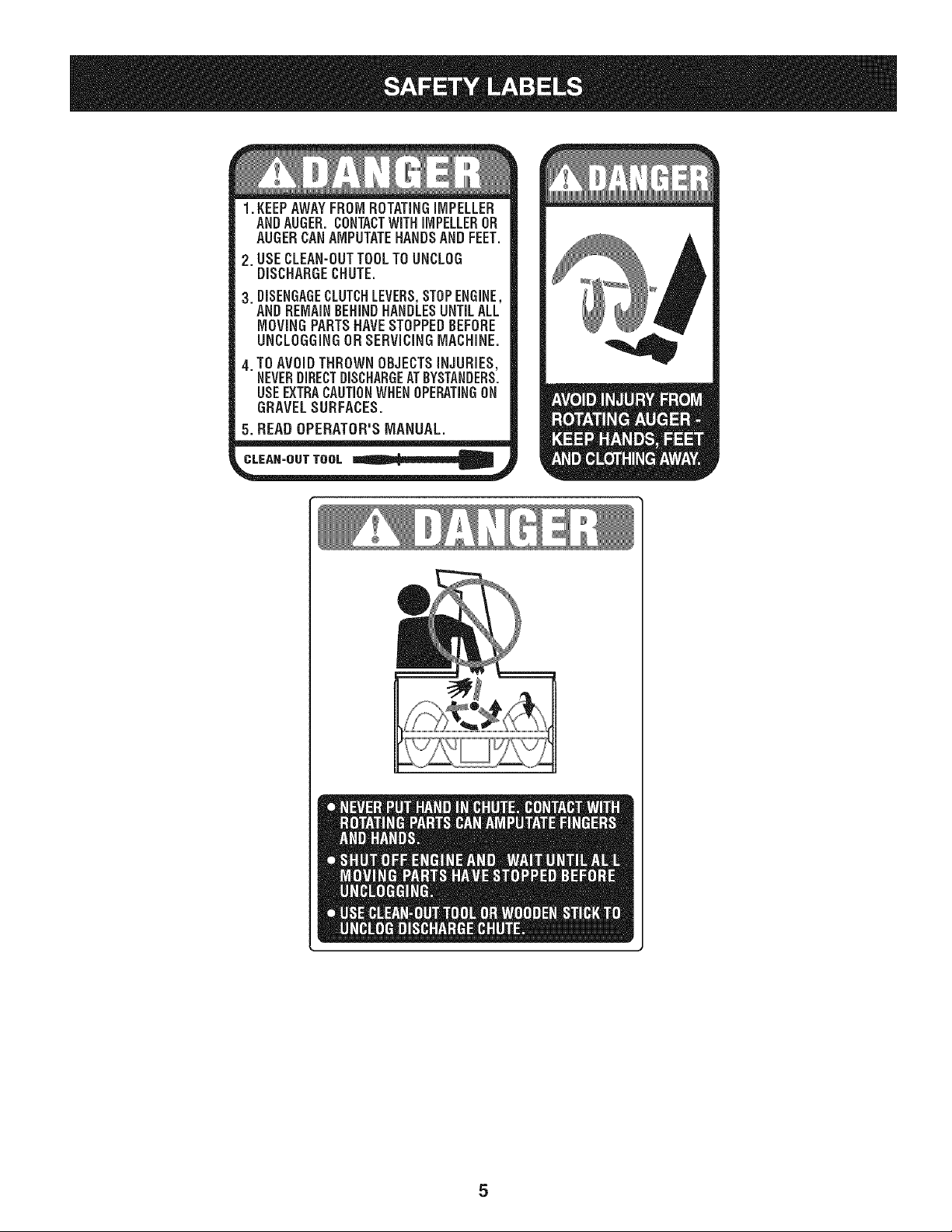
1. KEEPAWAYFROMROTATINGiMPELLER
ANDAUGER.CONTACTWiTHiMPELLEROR
AUGERCANAMPUTATEHANDSANDFEET.
2. USECLEAN-OUTTOOLTOUNCLOG
DISCHARGECHUTE.
3. DISENGAGECLUTCHLEVERS,STOPENGINE,
ANDREMAINBEHINDHANDLESUNTILALL
MOVINGPARTSHAVESTOPPEDBEFORE
UNCLOGGINGDRSERViCiNGMACHINE.
4. TOAVOIDTHROWNOBJECTSiNJURiES,
NEVERDIRECTDISCHARGEATBYSTANDERS.
USEEXTRACAUTIONWHENOPERATINGON
GRAVELSURFACES.
5. READOPERATOR'SMANUAL.
CLEAN-OUT TOOL
5
NOTE:Referencesto rightor leftsideof the snowthrowerare
determinedfrombehindthe unit inthe operatingposition(standing
directlybehindthesnowthrower,facing the handlepanel).
REMOVING FROM CRATE
1. Removescrewsfromthe bottomof the cratesecuringthe sides,
andendsof the shippingcrate.
2. Lift off the top off of the crate and set out of the wayof the
assemblyarea.
3. Removeand discardplasticbagthat coversunit.
4. Removeany loosepartsincludedwith unit(i.e.,Operator's
Manual,etc.).
5. Pushdownon the lowerhandleand pull unitback outof crate.
6. Makecertainthe crate has beencompletelyemptiedbefore
discardingit.
ASSEMBLY
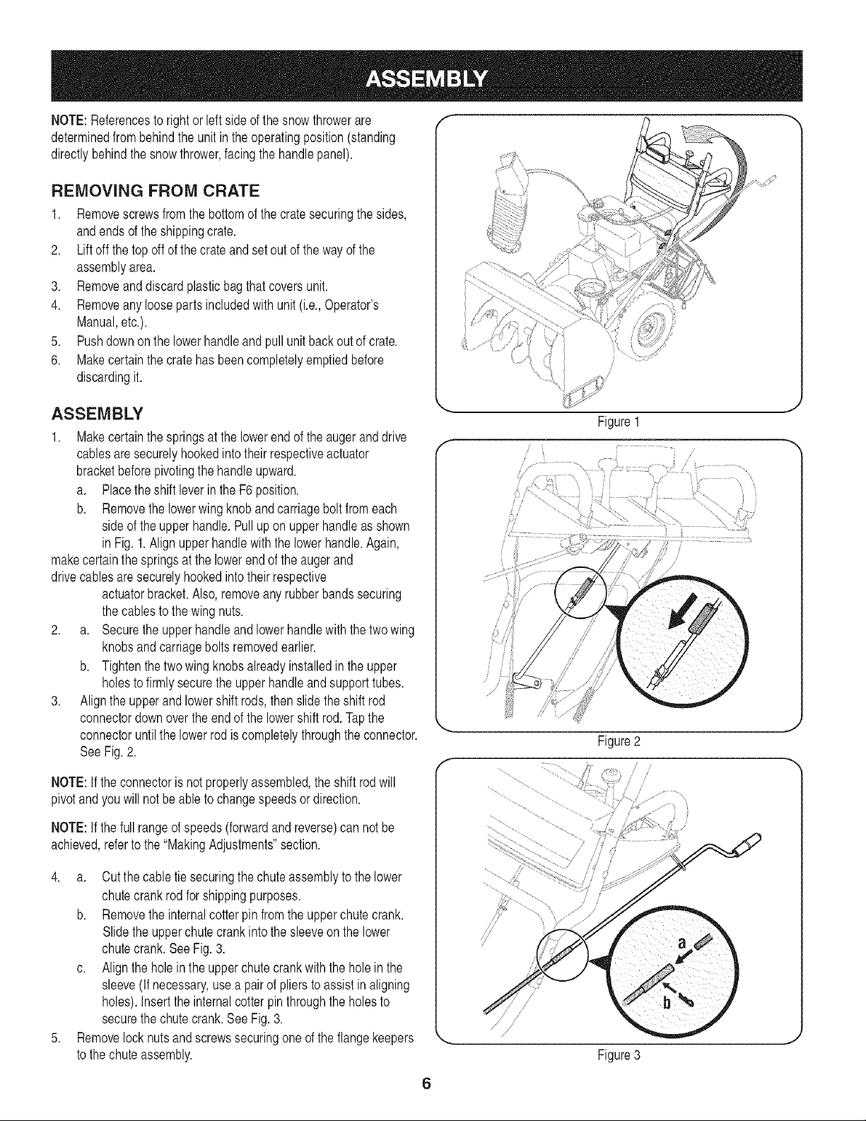
1. Makecertainthe springsat the lowerend of the auger anddrive
cablesaresecurelyhookedintotheir respectiveactuator
bracketbeforepivotingthe handle upward.
a. Placetheshift leverin the F6 position.
b. Removethe lowerwing knoband carriagebolt fromeach
sideof theupperhandle.Pull up on upper handleas shown
in Fig.1.Alignupperhandlewiththe lowerhandle.Again,
makecertainthe springsat the lowerend of the augerand
drivecablesaresecurelyhookedintotheir respective
actuatorbracket.Also, removeanyrubberbandssecuring
the cablesto the wingnuts.
2. a. Securethe upper handleand lowerhandlewith thetwo wing
knobsandcarriagebolts removedearlier.
b. Tightenthetwo wingknobsalreadyinstalledin the upper
holesto firmlysecurethe upperhandleandsupporttubes.
3. Alignthe upperand lowershift rods,thenslidethe shift rod
connectordownoverthe end of the lowershift rod.Tapthe
connectoruntilthe lowerrod is completelythroughthe connector.
SeeFig.2.
NOTE:If theconnectoris notproperlyassembled,the shift rodwill
pivotand youwill notbe ableto changespeedsor direction.
NOTE:If thefull rangeof speeds(forwardandreverse)can notbe
achieved,referto the "MakingAdjustments"section.
4. a. Cutthe cabletie securingthe chuteassemblyto the lower
chutecrankrod for shippingpurposes.
b. Removethe internalcotterpin from the upperchutecrank.
Slidethe upperchutecrankinto the sleeveon the lower
chutecrank. SeeFig.3.
c. Alignthe holein the upperchutecrankwiththe holein the
sleeve(If necessary,usea pair of pliers toassist in aligning
holes).Insertthe internalcotterpin throughthe holesto
securethe chutecrank.SeeFig. 3.
5. Removelock nuts andscrewssecuringone of the flangekeepers
to the chuteassembly.
f
Figure1
/
/ .........
/
ii
J ii
Figure2
/
/
/
Figure3
J
6
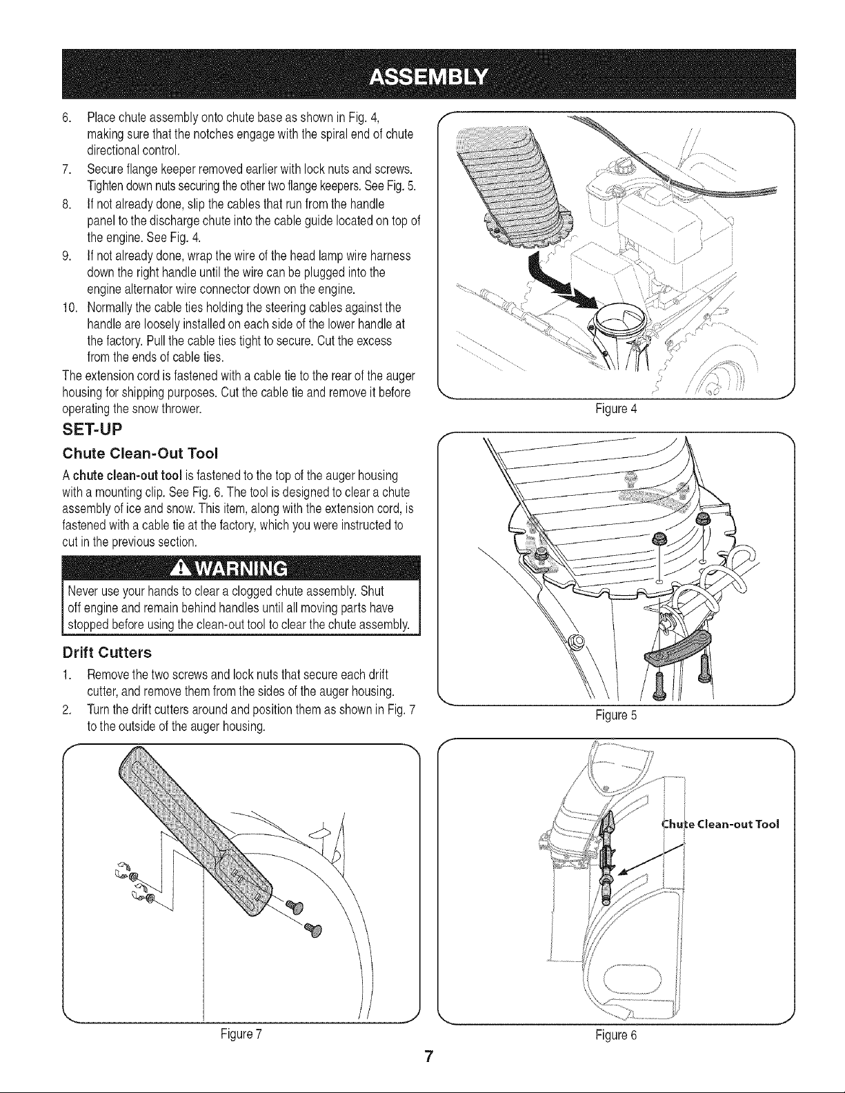
6. Placechuteassemblyontochutebaseas shown in Fig. 4,
makingsurethatthe notchesengagewith the spiralend of chute
directionalcontrol.
7. Secureflangekeeperremovedearlierwith lock nuts and screws.
Tightendownnutssecuringtheothertwoflangekeepers.SeeFig.5.
8. If notalreadydone,slip the cablesthat run fromthe handle
panelto the dischargechuteintothe cableguide locatedon top of
the engine.See Fig. 4.
9. If notalreadydone,wrap thewire of the head lampwireharness
downthe righthandleuntil thewire canbe pluggedintothe
enginealternatorwireconnectordownon theengine.
10. Normallythe cableties holdingthe steeringcablesagainstthe
handleareloosely installedon eachside of the lowerhandleat
the factory.Pull thecable ties tight to secure.Cut the excess
fromtheends of cableties.
The extensioncord is fastenedwitha cabletie to the rearof theauger
housingfor shippingpurposes.Cut the cabletie and removeit before
operatingthesnow thrower.
SET-UP
Chute Clean=Out Tool
Achute clean-out tool is fastenedto the top of the augerhousing
witha mountingclip.SeeFig.6. The toolis designedto clear a chute
assemblyof ice andsnow.This item,alongwiththe extensioncord,is
fastenedwith a cabletie at the factory,whichyou wereinstructedto
cut inthe previoussection.
Neveruseyour handsto cleara cloggedchuteassembly.Shut
off engineandremainbehindhandlesuntilall movingpartshave
stoppedbeforeusingthe clean-outtoolto clear thechute assembly.
Drift Cutters
1. Removethe twoscrewsand locknutsthat secureeachdrift
cutter,andremovethem from thesides of the auger housing.
2. Turnthe drift cuttersaroundand positionthem asshown in Fig.7
to the outsideof the augerhousing.
1i
ii
Figure4
\
Figure5
-=hule Clean-out Tool
Figure7
7
Figure6
3. Attachthedriftcutterswiththescrewsandlocknutsremoved
earlier.
Tire Pressure
Beforeoperating,checktire pressure.Referto thetire sidewallfor
exacttire manufacturer'srecommendedor maximumpsi.
NOTE:If the tire pressureis notequalin bothtires,the unit maynot
travelina straightpathandthe shaveplatemaywearunevenly.
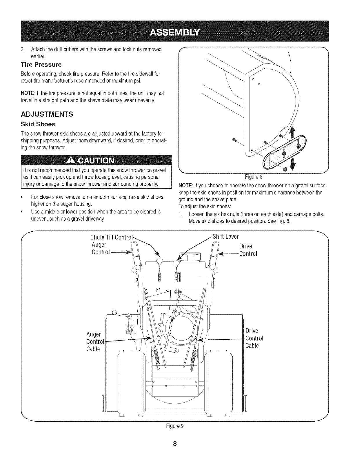
ADJUSTMENTS
Skid Shoes
The snowthrowerskidshoesareadjustedupwardat the factoryfor
shippingpurposes.Adjust themdownward,if desired,priorto operat-
ingthe snowthrower.
It is not recommendedthat you operatethis snowthroweron gravel
as it can easilypick upandthrowloosegravel,causingpersonal
injuryor damageto the snowthrowerandsurroundingproperty.
,, Forclose snowremovalon a smoothsurface,raiseskid shoes
higheronthe auger housing.
,, Usea middleor lowerpositionwhenthe area to be clearedis
uneven,suchas a graveldriveway
f
Chute Tilt
Auger
Control --
Figure8
NOTE:If youchoosetooperatethe snowthrowerona gravelsurface,
keepthe skid shoes in positionfor maximumclearancebetweenthe
groundandthe shaveplate.
Toadjustthe skidshoes:
1. Loosenthesix hex nuts (threeon eachside)and carriagebolts.
Moveskid shoesto desiredposition.SeeFig.8.
Drive
Shift Lever
Auger
Control
Cable
z
Drive
Control
Cable
Figure9
J
8
2. Makecertainthe entire bottomsurfaceofskid shoe is againstthe
groundto avoidunevenwearon the skid shoes.
3. Retightennutsand boltssecurely.
Testing Auger Drive Control
Priorto operatingyoursnow thrower,carefullyread and followall
instructionsbelow.Performall adjustmentsto verifyyoursnow
throweris operatingsafelyand properly.
When theaugercontrolis releasedand inthe disengaged"up"posi-
tion,thecable shouldhavevery little slack, but shouldNOTbe tight.
1. In a well-ventilatedarea,start the snowthrowerengineas
instructedin theO_erationsection.Makesure thethrottle is setin
the fastposition_. ,
2. Whilestandingin the operators position(behindthe snow
thrower),engagethe auger controland allowthe augerto remain
engagedfor approximatelytensecondsbeforereleasingthe
augercontrol.Repeatthis severaltimes.
3. With theengine runningin the fastposition_ andthe auger
controlin thedisengaged"up"position,walkto thefrontof the
machine.Confirmthat the augerhas completelystopped rotating
andshowsno signsof motion.
4. If the augershowsany signsof rotating,immediatelyreturnto the
operator'spositionandshutoff the engine.Wait forall moving
partsto stopbeforereadjustingthe augercontrolcable.
Testing Drive Control & Shift Lever
Referto Fig.9 for locationof controls.
1. Movethe shift leverintosixth (6) position.
2. With thewheeldrivecontrol released,pushthe snowthrower
forward,then pull it back.The machineshouldmovefreely.
3. Engagethe drivecontroland attemptto movethe machineboth
forwardandback,resistanceshouldbe felt.
4. Movethe shift leverintothe fast reverse(R2) positionand repeat
the previoustwosteps.
If youexperiencedresistancerollingthe unit,eitherwhenrepositioning
the shift leverfrom6 to R2 orwhenattemptingto movethe machine
withthe drivecontrolreleased,adjustthedrive controlimmediately.
SeeAdjustingDrive and AugerControls.
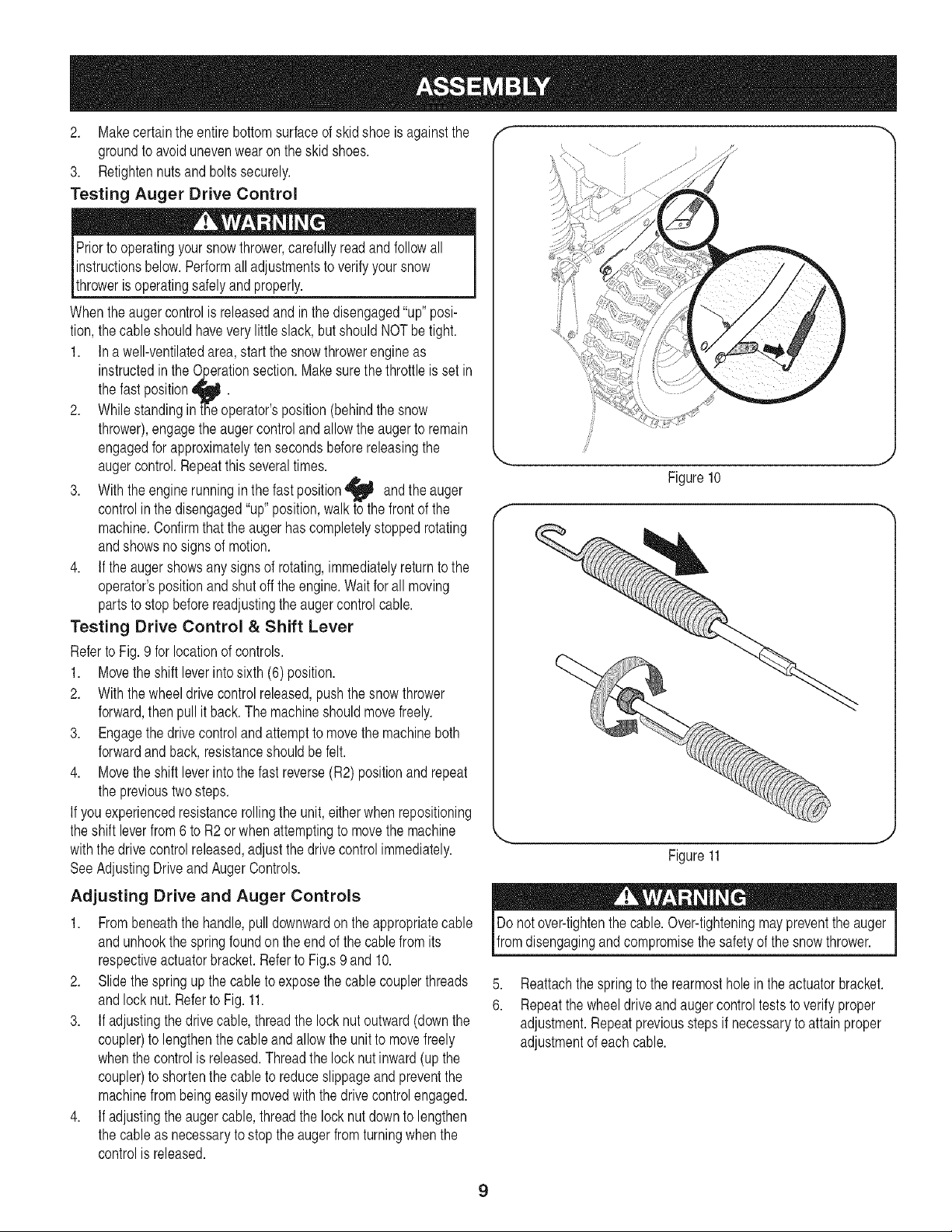
Adjusting Drive and Auger Controls
1. Frombeneaththe handle,pull downwardon theappropriatecable
andunhookthe springfoundon the end of the cablefrom its
respectiveactuatorbracket.Referto Fig.s9 and10.
2. Slide thespringup the cableto exposethe cablecouplerthreads
andlock nut. Referto Fig. 11.
3. If adjustingthe drivecable,threadthe lock nut outward(downthe
coupler)to lengthenthe cableandallowthe unit to movefreely
whenthe controlis released.Threadthe locknutinward(up the
coupler)to shortenthe cableto reduceslippageand preventthe
machinefrombeingeasilymovedwith the drivecontrolengaged.
4. If adjustingthe augercable, threadthe lock nut downto lengthen
the cableas necessaryto stopthe augerfromturningwhen the
controlis released.
f
4
Figure10
,,.,,
Figure11
Do notover-tightenthe cable.Over-tighteningmaypreventtheauger I
Ifrom dsengagngand compromse the safetyof the snow thrower. J
5,
6.
Reattachthe springto the rearmostholein the actuatorbracket.
Repeatthe wheeldriveandaugercontroltests to verifyproper
adjustment.Repeatpreviousstepsif necessaryto attain proper
adjustmentof eachcable.
9
Chute
Drift Assembl
Cutters
Augers
OilFill
Gas Ca
Headlk
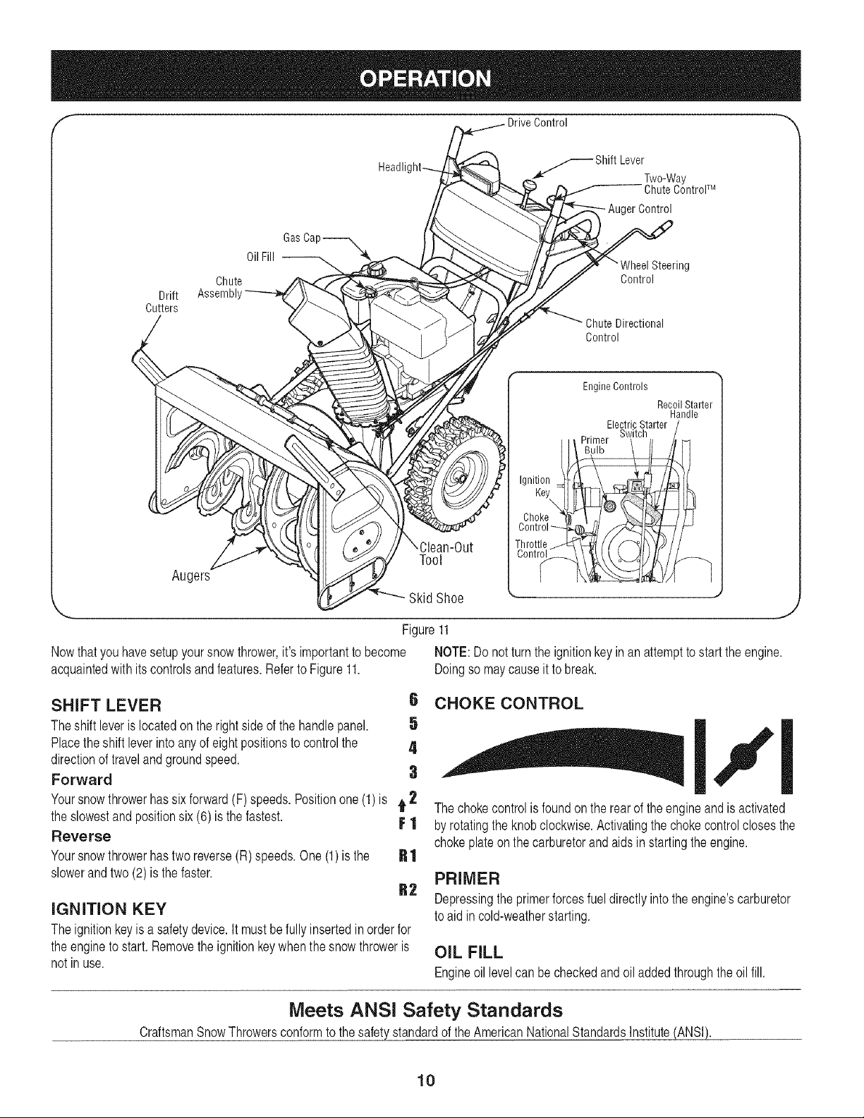
Nowthatyouhavesetupyoursnow thrower,it's importantto become
acquaintedwith itscontrolsand features.Referto Figure11.
Tool
Skid Shoe
s Shift LeverTwo_Way
Chute ControlTM
Auger Control
g
Control
Chute Directional
Control
Ignition =
Key
\
Choke
Control
Throttle /
Contr_t_
EngineControls
RecoilStarter
Handle
ElectricStarter /
. Switch /
,J
Figure11
NOTE:Do not turnthe ignitionkeyinan attemptto startthe engine.
Doingso maycauseit to break.
SHIFT LEVER
Theshift leveris locatedon the rightsideof the handlepanel.
Placetheshift leverinto anyof eightpositionsto controlthe
directionof travelandgroundspeed.
Forward
6 CHOKE CONTROL
Yoursnowthrowerhassix forward(F) speeds.Positionone(1)is t 2 The chokecontrolis foundon the rearof theengineandis activated
FI
R1
R2
the slowestand positionsix (6) is the fastest.
Reverse
Yoursnowthrowerhastwo reverse(R)speeds.One(1)is the
slowerandtwo (2) is the faster.
I,,'l
byrotatingthe knobclockwise.Activatingthechokecontrolclosesthe
chokeplateon the carburetorand aids in startingthe engine.
PRIMER
Depressingthe primerforcesfueldirectlyinto theengine'scarburetor
to aid incold-weatherstarting.
IGNITION KEY
The ignitionkey is a safety device. It must be fullyinserted in order for
the engine to start. Remove the ignitionkey when the snow throweris
not in use.
OIL FILL
Engineoil levelcan becheckedandoil addedthroughthe oil fill.
Meets ANSI Safety Standards
CraftsmanSnowThrowersconformto thesafety standardof the AmericanNationalStandardsInstitute(ANSI).
10
THROTTLE CONTROL
The throttlecontrolis locatedonthe rear of theengine.
It regulatesthe speedof the engineandwillshutoff the
enginewhenmovedintothe STOPposition.
SKID SHOES
Positionthe skidshoesbasedon surfaceconditions.Adjust
upwardfor hard-packedsnow.Adjustdownwardwhen
operatingon gravelor crushedrock surfaces.
RECOIL STARTER HANDLE
This handleis usedto manuallystart theengine.
ELECTRIC STARTER BUTTON
Pressingthe electricstarterbuttonengagesthe engine's
electricstarterwhen pluggedintoa 120Vpowersource.
ELECTRIC STARTER OUTLET
Requiresthe use ofa three-prongoutdoorextensioncord (included)
anda 120Vpowersource/walloutlet.
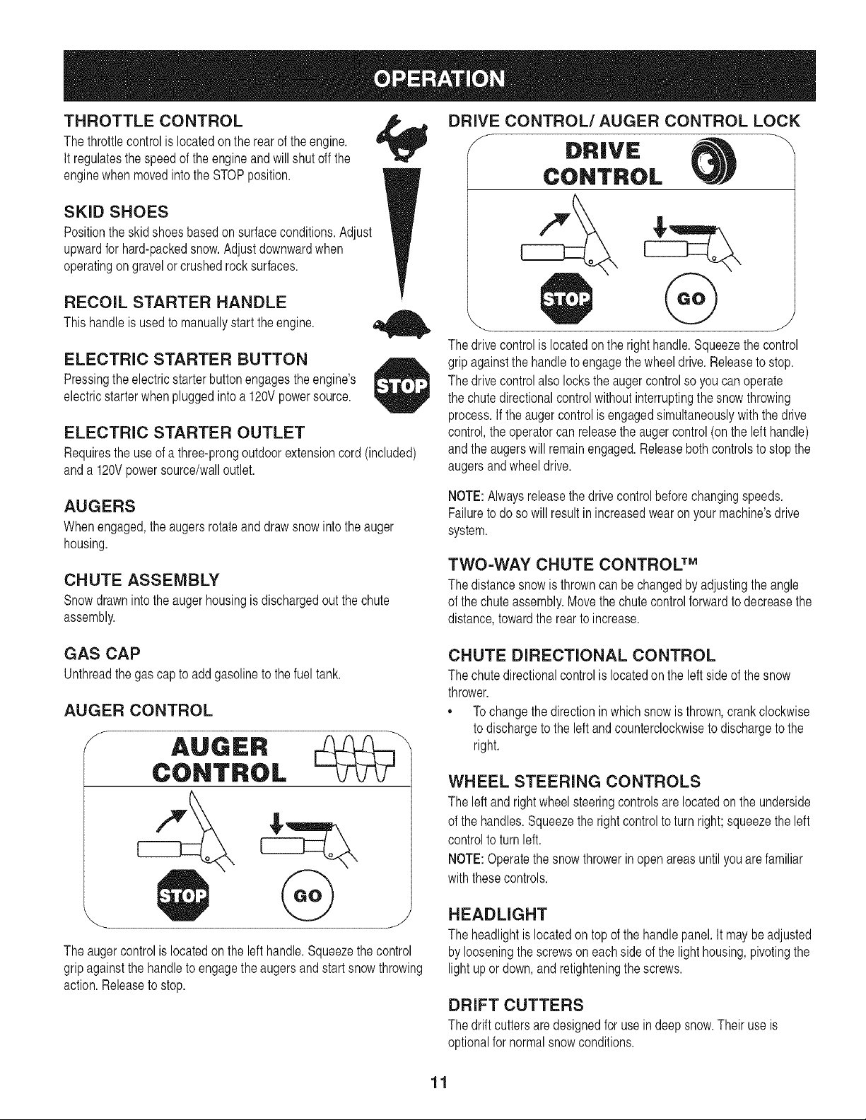
DRIVE CONTROL/AUGER CONTROL LOCK
f
DRIVE
CONTROL
@
The drivecontrolis locatedon the righthandle.Squeezethe control
gripagainstthe handleto engagethe wheeldrive.Releaseto stop.
The drivecontrolalso locksthe augercontrolso you canoperate
the chutedirectionalcontrolwithoutinterruptingthe snowthrowing
process.If the augercontrolis engagedsimultaneouslywith the drive
control,the operatorcanreleasetheauger control(on the left handle)
andthe augerswill remainengaged.Releaseboth controlsto stopthe
augersandwheeldrive.
AUGERS
When engaged,the augersrotateand drawsnow intothe auger
housing.
CHUTE ASSEMBLY
Snowdrawnintothe augerhousingis dischargedout the chute
assembly.
NOTE:Alwaysreleasethedrive controlbeforechangingspeeds.
Failureto doso will resultinincreasedwearon yourmachine'sdrive
system.
TWO=WAY CHUTE CONTROL TM
The distancesnow is throwncan bechangedby adjustingthe angle
of thechuteassembly.Movethe chutecontrol forwardto decreasethe
distance,towardthe rearto increase.
GAS CAP
Unthreadthe gascap to addgasolineto thefuel tank.
AUGER CONTROL
S
The augercontrolis locatedonthe lefthandle.Squeezethe control
gripagainstthe handleto engagethe augersand start snowthrowing
action.Releaseto stop.
CHUTE DIRECTIONAL CONTROL
The chutedirectionalcontrolis locatedon the left sideof the snow
thrower.
,, Tochangethe directioninwhich snowis thrown,crankclockwise
to dischargeto the leftand counterclockwiseto dischargeto the
right.
WHEEL STEERING CONTROLS
The leftand rightwheelsteeringcontrolsare locatedonthe underside
of the handles.Squeezethe rightcontrolto turn right; squeezethe left
controlto turnleft.
NOTE:Operatethe snow throwerin open areasuntilyouare familiar
withthesecontrols.
HEADLIGHT
The headlightis locatedontop of the handlepanel.It maybeadjusted
by looseningthe screwson eachside of the lighthousing,pivotingthe
lightupor down,andretighteningthe screws.
DRIFT CUTTERS
The driftcuttersare designedfor usein deepsnow.Their use is
optionalfor normalsnowconditions.
11
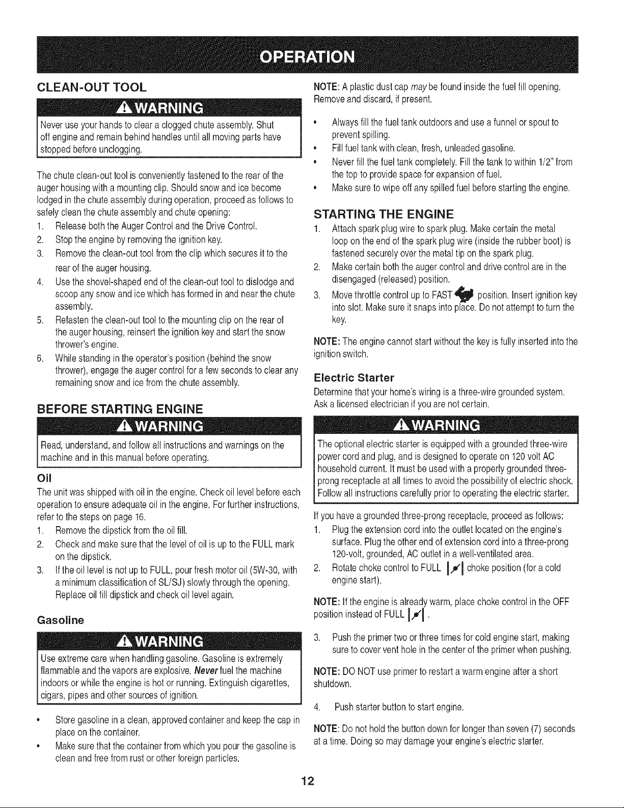
CLEAN-OUT TOOL NOTE:A plasticdustcap maybefound insidethe fuel fill opening.
Removeand discard,if present.
Neveruseyourhandsto cleara cloggedchuteassembly.Shut
off engineand remainbehindhandlesuntil allmovingpartshave
stoppedbeforeunclogging.
Thechuteclean-outtoolis convenientlyfastenedto the rearof the
augerhousingwith a mountingclip. Shouldsnowandice become
lodgedin the chuteassemblyduringoperation,proceedas followsto
safelycleanthechuteassemblyand chute opening:
1. ReleaseboththeAuger Controland the DriveControl.
2. Stopthe engineby removingthe ignitionkey.
3. Removethe clean-outtool fromthe clip whichsecuresit to the
rearof the augerhousing.
4. Use theshovel-shapedendof the clean-outtool to dislodgeand
scoopany snowandice which hasformedin andnearthechute
assembly.
5. Refastenthe clean-outtool to the mountingclip on the rearof
theaugerhousing,reinsertthe ignitionkey and startthe snow
thrower'sengine.
6. Whilestandingin the operator'sposition(behindthe snow
thrower),engagethe auger controlfora few secondsto clearany
remainingsnow and ice from thechute assembly.
BEFORE STARTING ENGINE
Read,understand,and followall instructionsandwarningsonthe
machineand inthis manualbeforeoperating.
Oil
Theunit wasshippedwith oil inthe engine.Checkoil levelbeforeeach
operationto ensureadequateoil in the engine.Forfurtherinstructions,
referto the stepsonpage 16.
1. Removethe dipstickfromthe oilfill.
2. Checkand makesurethat the levelof oil is up to theFULL mark
onthe dipstick.
3. If theoil levelis notup to FULL,pourfresh motoroil (5W-30,with
a minimumclassificationof SL/SJ) slowlythroughthe opening.
Replaceoil fill dipstickandcheckoil levelagain.
Gasoline
Useextremecarewhenhandlinggasoline.Gasolineis extremely
flammableand the vaporsare explosive.Neverfuel the machine
indoorsor whilethe engineis hot or running.Extinguishcigarettes,
[c gars,ppesand othersourcesof gnt on.
,, Storegasolinein a clean, approvedcontainerandkeepthe cap in
placeonthe container.
,, Makesurethatthe containerfrom which you pourthe gasolineis
cleanandfreefrom rust or otherforeignparticles.
,, Alwaysfill thefuel tank outdoorsand usea funnelor spout to
preventspilling.
,, Fillfuel tank with clean,fresh,unleadedgasoline.
,, Neverfill thefuel tankcompletely.Fillthe tankto within1/2" from
the top to providespaceforexpansionof fuel.
,, Makesureto wipeoff anyspilledfuel beforestartingthe engine.
STARTING THE ENGINE
1. Attachspark plugwire to spark plug.Makecertainthe metal
loopon theend of the sparkplugwire(insidethe rubberboot) is
fastenedsecurelyoverthe metaltip on the spark plug.
2. Makecertainboththe auger controland drivecontrolare in the
disengaged(released)position.
3. Movethrottlecontrol up to FAST_ position.Insertignitionkey
intoslot. Makesureit snapsinto place.Donot attemptto turn the
key.
NOTE:The enginecannotstart withoutthe keyis fullyinsertedintothe
ignitionswitch.
Electric Starter
Determinethat yourhome'swiringis a three-wiregroundedsystem.
Aska licensedelectricianif you arenot certain.
The optionalelectricstarteris equippedwitha groundedthree-wire
powercordandplug,and is designedto operateon 120voltAC
householdcurrent.It mustbe usedwith aproperlygroundedthree-
prongreceptacleat all timesto avoidthepossibilityof electricshock.
Followall instructionscarefullyprior to operatingthe electricstarter.
Ifyou havea groundedthree-prongreceptacle,proceedas follows:
1. Plugthe extensioncord intothe outletlocatedonthe engine's
surface.Plugtheotherend of extensioncordinto a three-prong
120-volt,grounded,ACoutlet in a well-ventilatedarea.
2. Rotatechokecontrolto FULL I,.#'1chokeposition(for a cold
enginestart).
NOTE:If theengineis alreadywarm,placechokecontrolin the OFF
positioninsteadof FULL IJl •
3. Pushtheprimertwoor threetimesfor coldenginestart, making
sureto coverventhole in the centerof the primerwhenpushing.
NOTE:DO NOTuse primerto restarta warmengineaftera short
shutdown.
4. Pushstarterbuttonto start engine.
NOTE:Do not holdthe buttondownfor longerthanseven(7)seconds
at a time. Doingso maydamageyourengine'selectricstarter.
12
5. Oncethe engine starts,releasestarterbutton.
6. As the enginewarms,slowlyrotatechokecontrolto theOFF
position.Ifthe enginefalters,quicklyrotatechoke controlback to
FULL 14D"Ithenslowlyintothe OFFpositionagain.
7. Whendisconnectingthe extensioncord, alwaysunplugthe end
at the three-prongwall outletbeforeunpluggingthe oppositeend
fromthe snowthrower.
Recoil Starter
1. Rotatechoke controlto FULL IJl choke position(coldengine
start).
NOTE: Ifthe engineis alreadywarm, placechokecontrolinthe OFF
insteadof FULLIJ|.
position
2. Pushthe primertwo or threetimes forcold enginestart, making
sureto coverventhole in the centerof the primerwhenpushing.
NOTE: DONOTuseprimerto restartawarmengineaftera short
shutdown.
NOTE:Additionalprimingmaybe necessaryif the temperatureis
below15° Fahrenheit.
3. Graspthe recoilstarterhandleand slowlypull the rope out. At the
pointwhereit becomesslightlyharderto pullthe rope,slowly
allowthe ropeto recoil.
4. Pull the starterhandlewith a firm,rapid stroke.Do notrelease
the handleandallowit to snapback.Keepa firm holdon the
starterhandleandallow it to slowlyrecoil.
5. As the enginewarms,slowlyrotatethe chokecontrolto the OFF
position.Ifthe enginefalters,quicklyrotatethe chokecontrol
backto the FULL I,_1 positionandthenslowlyinto the OFF
positionagain.
NOTE:Allowthe engineto warmupfor afew minutesafterstarting.
The enginewill notdevelopfull poweruntilit reachesoperating
temperatures.
STOPPING THE ENGINE
Runenginefor a fewminutesbeforestoppingto helpdry off any
moistureonthe engine.
Movethrottlecontrolto STOP
1.
position.
2. Removethe ignitionkeyandstoreina safeplace.
3. Wipeall snowand moisturefrom the areaaroundthe engineas
wellas the areainand aroundthe drivecontrolandaugercontrol.
Also,engageandreleasebothcontrolsseveraltimes.
TO ENGAGE DRIVE
1. With thethrottlecontrol in the Fast_ position,moveshift lever
intooneof the six forward(F) positionsor tworeverse(R)
positions.Selecta speedappropriatefor the snow conditionsand
a paceyou'recomfortablewith.
NOTE: Whenselectinga DriveSpeed,usethe slowerspeedsuntil
you arecomfortableandfamiliarwith theoperationof the snow
thrower.
2. Squeezethe drivecontrolagainstthe handlethe snowthrower
will move.Releaseit anddrivemotionwill stop.
NOTE:NEVERrepositionthe shift lever(changespeedsor direction
of travel)withoutfirst releasingthedrive controland bringingthesnow
throwerto a completestop.Doingso will resultin prematurewearto
the snowthrower'sdrivesystem.
TO ENGAGE AUGERS
1. Toengagethe augersand startthrowingsnow,squeezethe
augercontrolagainstthe left handle.Releaseto stop the augers.
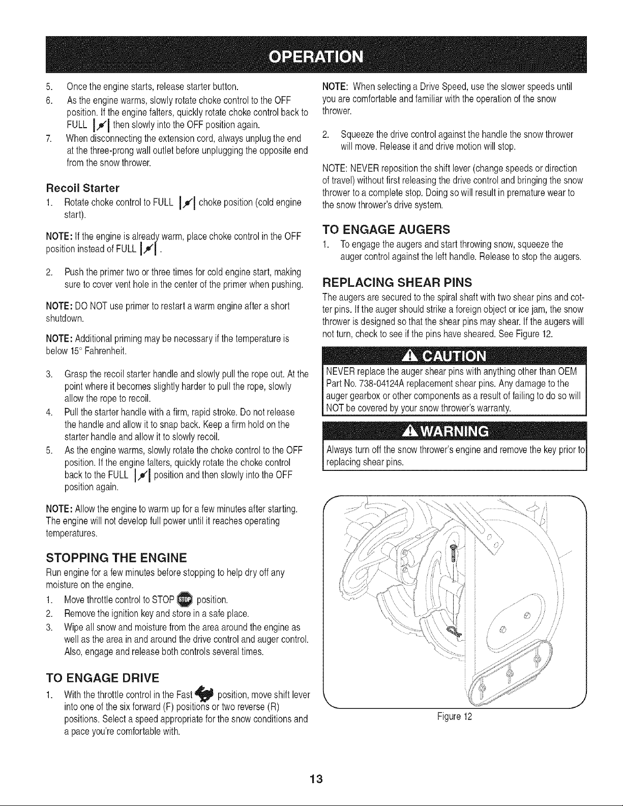
REPLACING SHEAR PiNS
The augersare securedto the spiralshaft with two shearpinsand cot-
ter pins.if theaugershouldstrikea foreignobjector ice jam,the snow
throweris designedso thatthe shearpins mayshear.Ifthe augerswill
notturn,checkto see if the pins havesheared.SeeFigure12.
NEVERreplacethe augershearpinswith anythingotherthan OEM
Part No.738-04124Areplacementshearpins.Any damageto the
augergearboxorothercomponentsas a resultof failingto do so will
NOTbecoveredbyyour snowthrower'swarranty.
Alwaysturnoffthe snowthrower'sengineand removethe key priortc
replacingshearpins.
//
Figure12
13
ENGINE MAINTENANCE
Beforelubricating,repairing,or inspecting,disengageall controls
land stopengine.Waituntilall movingpartshavecometo a complete
[stop.
Checking Engine Oil
1. Be sureengine is uprightand level
2. Unscrewoil fill capfrom oil fillertube andwipedipstickclean.
3. Screwoil fill capback into oil filler tube.Tightensecurely.
4. Unscrewand removeoil fill cap from oil filler tube. Noteoil level.
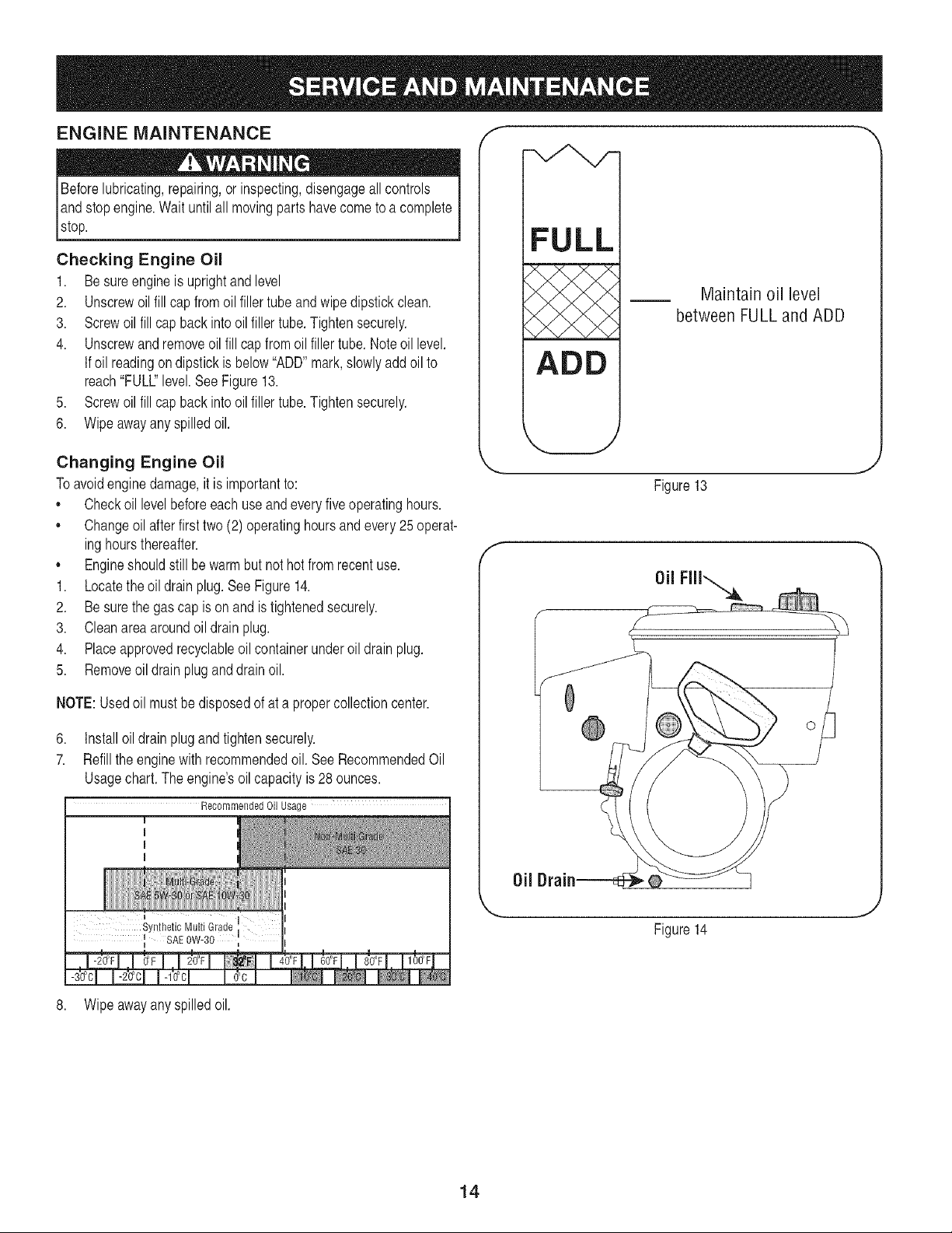
if oil readingondipstickis below"ADD"mark,slowlyadd oil to
reach"FULL"level.SeeFigure13.
5. Screwoil fill capback into oil filler tube.Tightensecurely.
6. Wipeawayany spilledoil.
Changing Engine Oil
Toavoidenginedamage,it is importantto:
,, Checkoil levelbeforeeachuse andevery five operatinghours.
,, Changeoil afterfirst two (2) operatinghoursand every25 operat-
inghoursthereafter.
,, Engineshouldstill be warmbut nothot from recentuse.
1. Locatethe oil drain plug.See Figure14.
2. Be surethe gas cap is on and istightenedsecurely.
3. Cleanareaaroundoil drain plug.
4. Placeapprovedrecyclableoilcontainerunderoil drainplug.
5. Removeoil drain pluganddrainoil.
NOTE:Usedoil mustbedisposedof at a propercollectioncenter.
6. Installoil drain plugand tightensecurely.
7. Refill the enginewith recommendedoil. SeeRecommendedOil
Usagechart.The engine'soilcapacityis 28 ounces.
Recommended Oil Usage
f
FULL
ADD
Maintain oil level
between FULL and ADD
Figure13
J
f
Oil
I
Synthetic Multi Grade
_ SAE 0W-30
',,_ _,
Figure14
8. Wipeawayany spilledoil.
14
Checking Spark Plug
Checksparkplugyearlyor every100operatinghours
1. Cleanarea aroundspark plug.
2. Removeand inspectspark plug.
3. Replacesparkplug if porcelainis crackedor if electrodesare
pitted,burnedorfouledwith deposits
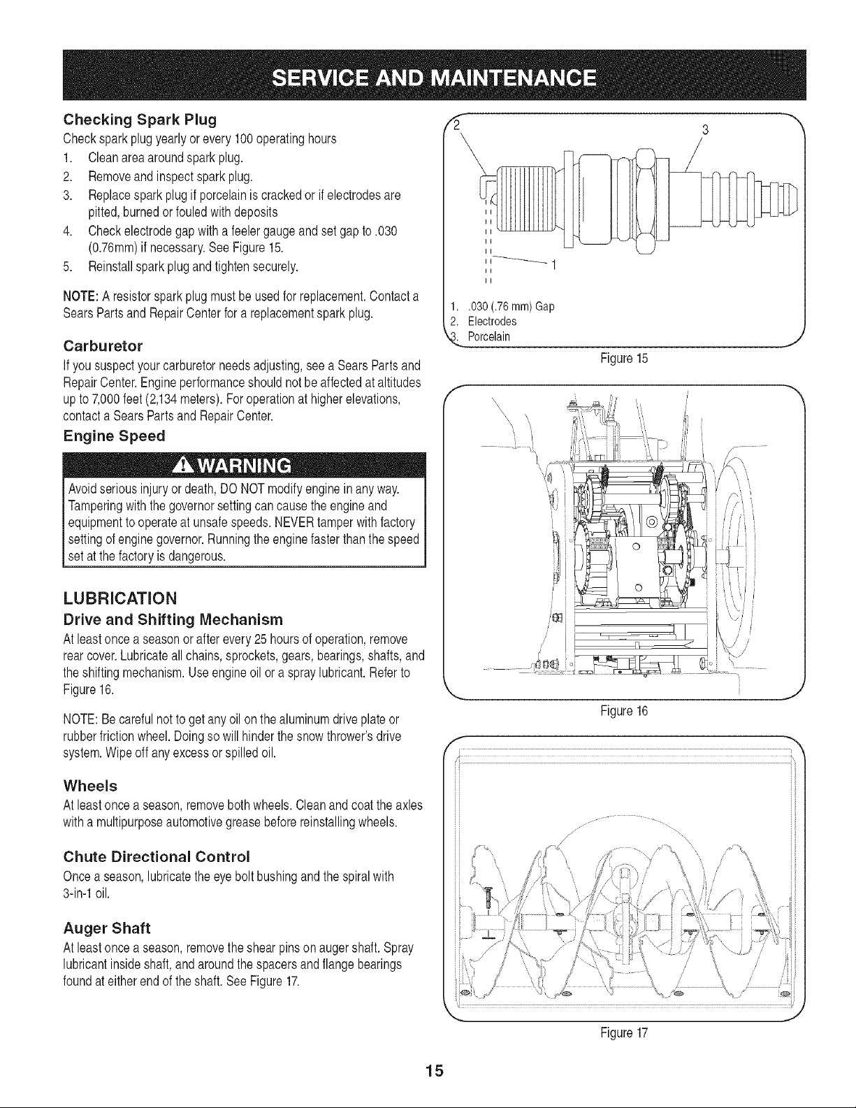
4. Checkelectrodegap with a feelergaugeand set gap to .030
(0.76ram)if necessary.See Figure15.
5. Reinstallsparkplugand tightensecurely.
NOTE:A resistorsparkplugmust beusedfor replacement.Contacta
SearsPartsand RepairCenterfor a replacementspark plug.
Carburetor
If yoususpectyourcarburetorneedsadjusting,seea SearsPartsand
RepairCenter.Engineperformanceshouldnotbe affectedat altitudes
upto 7,000feet(2,134meters).Foroperationat higherelevations,
contacta SearsPartsand RepairCenter.
Engine Speed
Avoidseriousinjuryor death,DO NOTmodifyenginein anyway.
Tamperingwiththegovernorsettingcancause the engineand
equipmentto operateat unsafespeeds.NEVERtamper with factory
settingof enginegovernor.Runningthe enginefasterthanthe speed
set at thefactoryis dangerous.
LUBRICATION
Drive and Shifting Mechanism
At leastonce a seasonorafterevery25hoursof operation,remove
rearcover.Lubricateall chains,sprockets,gears,bearings,shafts,and
the shiftingmechanism.Useengineoil or a spray lubricant.Referto
Figure16.
NOTE:Becarefulnotto getany oilon thealuminumdriveplateor
rubberfrictionwheel.Doingso will hinderthe snowthrower'sdrive
system.Wipeoff anyexcessor spilledoil.
Wheels
At leastonce a season,removebothwheels.Cleanand coat the axles
witha multipurposeautomotivegreasebeforereinstallingwheels.
Chute Directional Control
Oncea season,lubricatetheeye boltbushingandthe spiralwith
3-in-1oil.
Auger Shaft
At leastonce a season,removethe shearpinson augershaft.Spray
lubricantinsideshaft,andaroundthe spacersand flange bearings
foundat eitherendof the shaft. See Figure17.
3
II
II
1..030 (.76 ram)Gap
2. Electrodes
Porcelain
Figure15
J
f
,,, <¢_._ , , ,
i,, _ ',, i
,,,, _,,,
,,,, _ ,,, _ [
,, ,_ [
|¢
f
•••L.i,
i
,ji
Figure16
J
/
/ 7
/
J
Figure 17
15
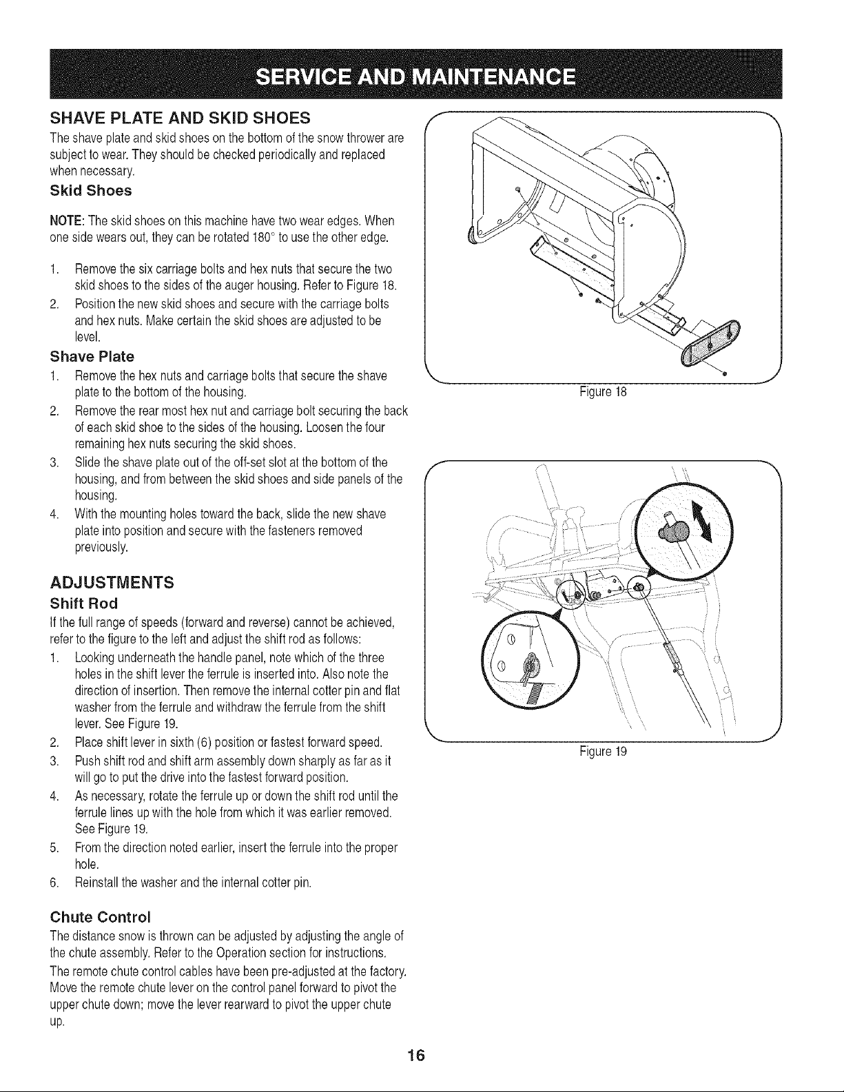
SHAVE PLATE AND SKID SHOES
Theshaveplateand skid shoes on the bottomof the snowthrowerare
subjectto wear.They shouldbe checkedperiodicallyand replaced
whennecessary.
Skid Shoes
NOTE:The skidshoeson this machinehavetwo wearedges.When
onesidewears out, theycan be rotated180° to usethe otheredge.
1. Removethe six carriageboltsandhexnutsthatsecurethe two
skidshoesto the sidesof the augerhousing.Referto Figure18.
2. Positionthe newskid shoesand securewith the carriagebolts
andhex nuts.Makecertainthe skid shoesare adjustedto be
level.
Shave Plate
1. Removethe hexnutsandcarriageboltsthatsecurethe shave
plateto the bottomof the housing.
2. Removethe rearmost hexnut andcarriageboltsecuringthe back
of eachskidshoeto the sidesof the housing.Loosenthefour
remaininghexnuts securingthe skid shoes.
3. Slide theshave plateoutof the off-setslot at the bottomof the
housing,andfrom betweentheskid shoes and side panelsof the
housing.
4. With the mountingholestowardthe back,slide the newshave
plateintopositionandsecurewith thefastenersremoved
previously.
ADJUSTMENTS
Shift Rod
If the fullrangeof speeds(forwardandreverse)cannotbe achieved,
referto the figureto the leftandadjustthe shift rodas follows:
1. Lookingunderneaththe handlepanel,notewhichof the three
holesinthe shift leverthe ferruleis insertedinto.Also notethe
directionof insertion.Thenremovethe internalcotterpin andflat
washerfromthe ferruleandwithdrawtheferrulefrom the shift
lever.SeeFigure19.
2. Placeshift leverin sixth (6) positionor fastestforwardspeed.
3. Pushshift rod and shiftarm assemblydownsharplyas far as it
willgo to put the driveintothe fastestforwardposition.
4. As necessary,rotatethe ferruleupor downthe shift rod untilthe
ferrulelinesupwiththe holefrom whichit wasearlierremoved.
SeeFigure19.
5. Fromthe directionnotedearlier,insertthe ferruleintothe proper
hole.
6. Reinstallthe washerandthe internalcotterpin.
f --,,
Figure18
\
\\
\ \
Chute Control
Thedistancesnowis throwncan beadjustedby adjustingthe angleof
the chuteassembly.Referto theOperationsectionfor instructions.
Theremotechutecontrolcableshavebeen pre-adjustedat the factory.
Movethe remotechuteleveron thecontrolpanelforwardto pivot the
upperchutedown; movethe leverrearwardto pivotthe upperchute
up.
16
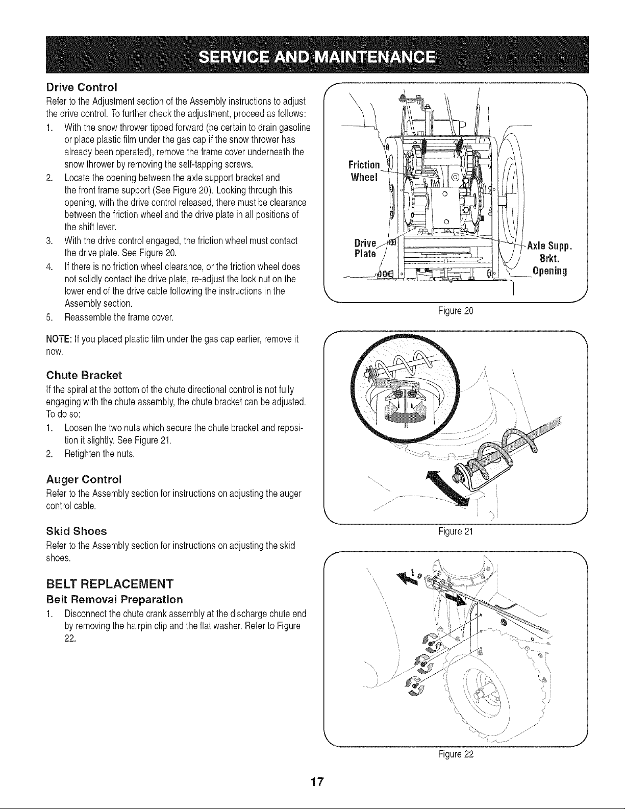
Drive Control
Referto the Adjustmentsectionof the Assemblyinstructionsto adjust
the drivecontrol.Tofurthercheckthe adjustment,proceedas follows:
1. With thesnow throwertippedforward (be certainto drain gasoline
orplace plasticfilm underthe gascap if the snowthrowerhas
alreadybeen operated),removetheframe coverunderneaththe
snowthrowerby removingthe self-tappingscrews.
2. Locatethe openingbetweenthe axlesupportbracketand
the frontframesupport(See Figure20). Lookingthroughthis
opening,with the drivecontrolreleased,theremustbe clearance
betweenthe frictionwheelandthe driveplatein allpositionsof
the shift lever.
3. With thedrive controlengaged,thefrictionwheelmustcontact
the driveplate.SeeFigure20.
4. If thereis no frictionwheelclearance,or the frictionwheeldoes
notsolidlycontactthe driveplate,re-adjustthe lock nuton the
lowerendof the drivecablefollowingthe instructionsinthe
Assemblysection.
5. Reassemblethe framecover.
NOTE:If youplacedplasticfilmunderthe gascap earlier,removeit
now.
Chute Bracket
If thespiral at the bottomof the chutedirectionalcontrolis not fully
engagingwiththe chute assembly,the chutebracketcan beadjusted.
To doso:
1. Loosenthe two nuts which securethechutebracketand reposi-
tion it slightly.SeeFigure21.
2. Retightenthenuts.
Auger Control
Referto the Assemblysectionfor instructionson adjustingthe auger
controlcable.
Skid Shoes
Referto the Assemblysectionfor instructionson adjustingthe skid
shoes.
f --,,
Friction
Wheel
DriveN
Plate!
Figure20
J
f
/
f
Figure21
J
BELT REPLACEMENT
Belt Removal Preparation
1. Disconnectthe chutecrankassemblyat the dischargechuteend
by removingthe hairpinclip andtheflat washer.Referto Figure
22.
,/
j,
.... JJ
Figure22
J
17
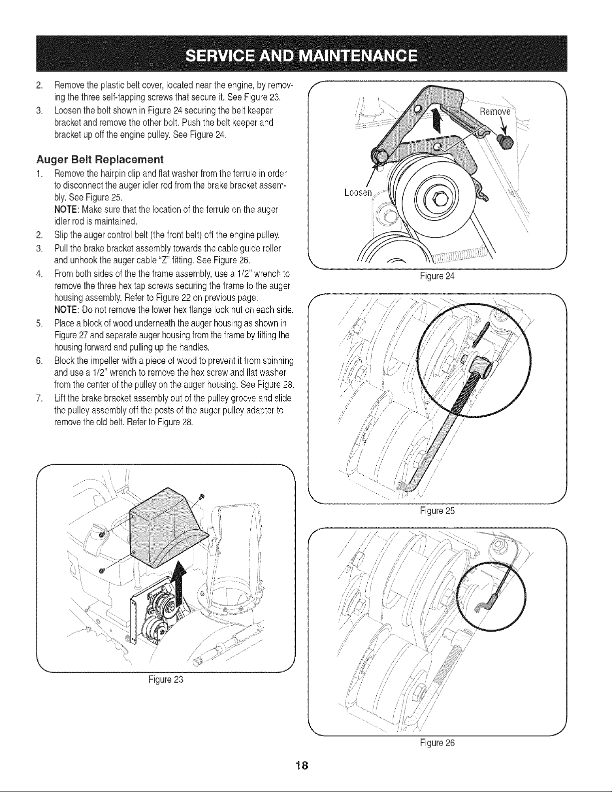
2. Removethe plasticbelt cover,locatedneartheengine,by remov-
ingthe threeself-tappingscrewsthat secureit. See Figure23.
3. Loosenthe bolt shownin Figure24 securingthe beltkeeper
bracketand removetheotherbolt. Pushthe beltkeeperand
bracketup offthe enginepulley.SeeFigure24.
Auger Belt Replacement
1. Removethe hairpinclip andflatwasherfromthe ferruleinorder
to disconnectthe augeridlerrod from the brakebracketassem-
bly.SeeFigure25.
NOTE:Makesurethatthe locationof the ferruleon the auger
idlerrodis maintained.
2. Slip the augercontrolbelt (the frontbelt) off the engine pulley.
3. Pull the brakebracketassemblytowardsthe cableguideroller
andunhookthe augercable"Z" fitting.SeeFigure26.
4. Frombothsides of the the frameassembly,usea 1/2" wrenchto
removethe threehex tap screwssecuringthe frameto the auger
housingassembly.Referto Figure22 on previouspage.
NOTE:Do notremovethe lowerhexflangelocknut oneachside.
5. Placea blockof woodunderneaththe augerhousingasshownin
Figure27andseparateaugerhousingfromthe framebytiltingthe
housingforwardand pullingup thehandles.
6. Blockthe impellerwith a pieceof woodto preventit fromspinning
andusea 1/2" wrenchto removethe hexscrewandflatwasher
fromthecenterofthe pulleyon the augerhousing.SeeFigure28.
7. Lift the brakebracketassemblyout of the pulleygrooveand slide
thepulleyassemblyoffthe postsof the auger pulleyadapterto
removetheoldbelt.Referto Figure28.
Figure23
f --,,
/
/
Loosen
i
Figure24
,,J
/
//
f
/" /, //
// //
// ,/
/
Figure25
Figure26
J
18
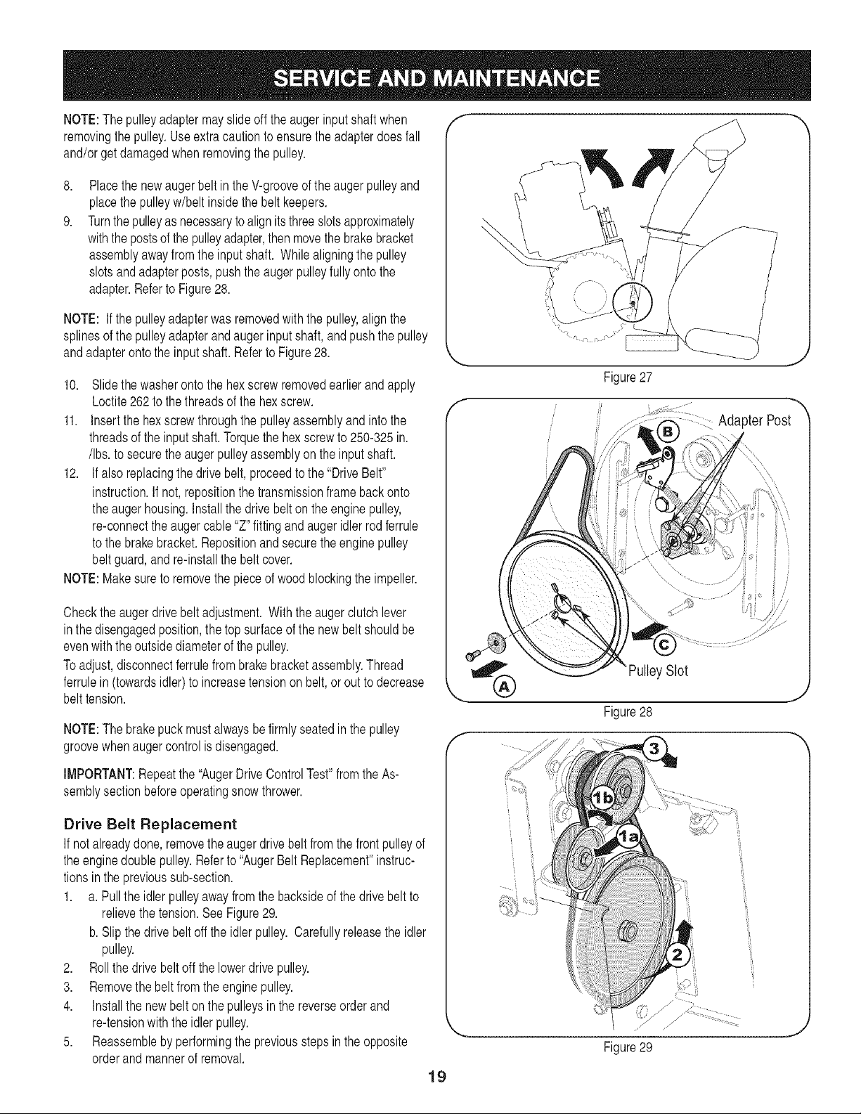
NOTE:The pulleyadaptermayslideoff the augerinputshaft when
removingthe pulley.Useextracautionto ensuretheadapterdoesfall
and/orget damagedwhenremovingthe pulley.
8,
9.
Placethe newaugerbelt in the V-grooveof the augerpulleyand
placethe pulleyw/belt insidethe beltkeepers.
Turnthe pulleyas necessarytoalignitsthreeslotsapproximately
withthe postsofthe pulleyadapter,thenmovethe brakebracket
assemblyawayfromthe inputshaft. Whilealigningthe pulley
slotsandadapterposts,pushthe auger pulleyfully ontothe
adapter.Referto Figure28.
NOTE: If the pulleyadapterwasremovedwiththe pulley,alignthe
splinesof the pulleyadapterand augerinputshaft, and pushthe pulley
andadapterontothe input shaft.Referto Figure28.
10. Slide thewasheronto the hexscrewremovedearlierand apply
Loctite262to the threadsof the hexscrew.
11. Insertthe hexscrewthroughthe pulleyassemblyand intothe
threadsof the inputshaft.Torquethe hexscrewto 250-325in.
/Ibs.to securethe augerpulleyassemblyon the inputshaft.
12. If also replacingthe drivebelt,proceedto the "DriveBelt"
instruction.If not,repositionthe transmissionframeback onto
the augerhousing.Installthe drivebelton the enginepulley,
re-connectthe augercable "Z" fittingandaugeridlerrodferrule
to the brakebracket.Repositionand securethe enginepulley
belt guard,andre-installthe beltcover.
NOTE:Makesureto removethe pieceof woodblockingthe impeller.
Checktheaugerdrivebelt adjustment.With the augerclutchlever
inthe disengagedposition,thetop surfaceof the newbelt shouldbe
evenwiththeoutsidediameterof the pulley.
To adjust,disconnectferrulefrom brakebracketassembly.Thread
ferrulein (towardsidler) to increasetensionon belt, or out to decrease
belt tension.
NOTE:The brakepuckmustalwaysbe firmly seatedinthe pulley
groovewhenaugercontrol is disengaged.
IMPORTANT:Repeatthe "AugerDriveControlTest"fromthe As-
semblysectionbeforeoperatingsnow thrower.
Drive Belt Replacement
If notalreadydone,removethe augerdrivebelt fromthe frontpulleyof
the enginedoublepulley.Referto "AugerBeltReplacement"instruc-
tionsin the previoussub-section.
1. a. Pull the idler pulleyaway fromthe backsideof the drivebelt to
relievethetension.SeeFigure29.
b. Slipthe drivebelt offthe idler pulley.Carefullyreleasethe idler
pulley.
2. Roll thedrive beltoff the lowerdrive pulley.
3. Removethe beltfrom the enginepulley.
4. Installthe newbelt on the pulleysin the reverseorder and
re-tensionwith theidlerpulley.
5. Reassembleby performingthe previousstepsin the opposite
orderandmannerof removal.
f
Adapter Post
,ySlot
Figure28
19
// ,/ j
Figure29
f --,,
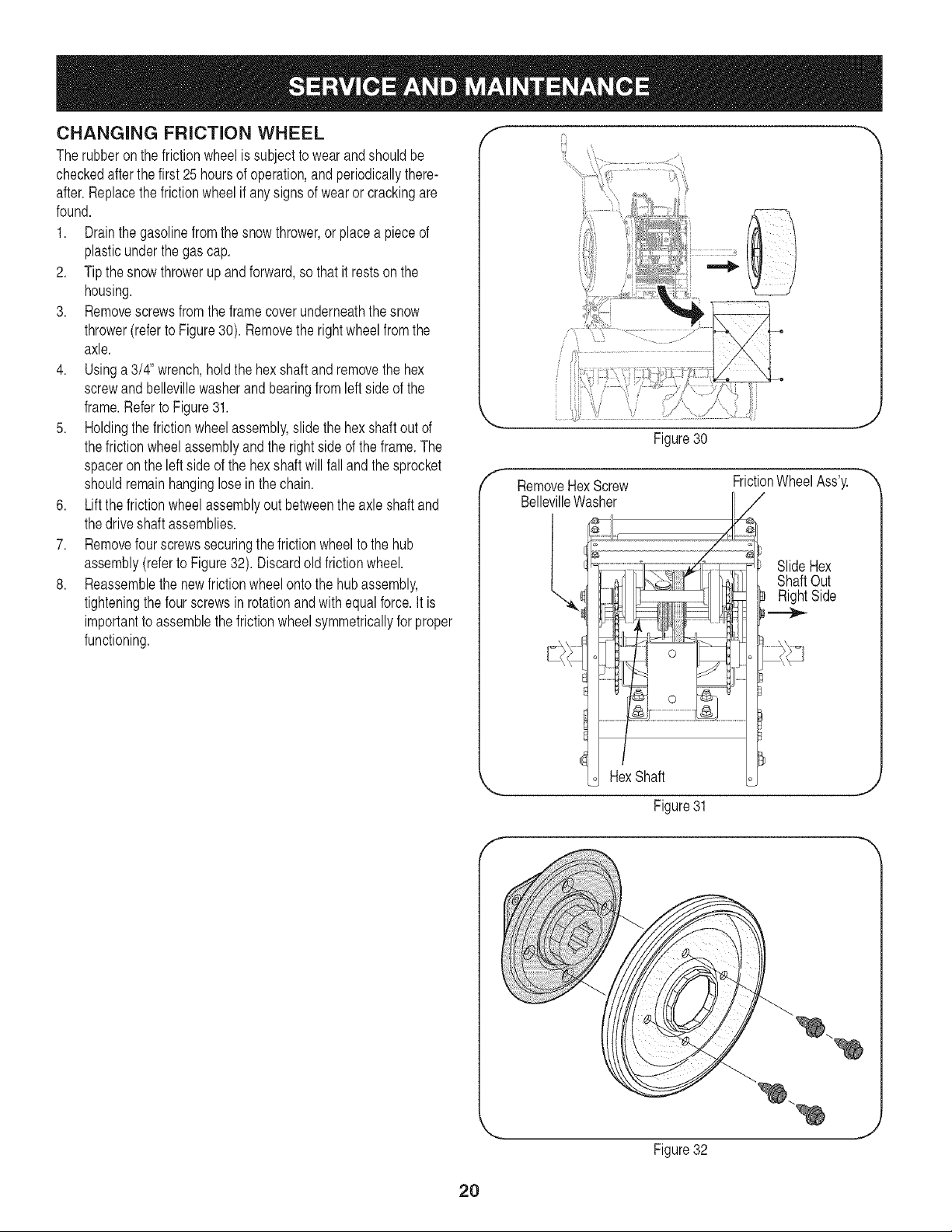
CHANGING FRICTION WHEEL
Therubberon the frictionwheelis subjectto wearandshouldbe
checkedafter thefirst 25 hoursof operation,andperiodicallythere-
after.Replacethe frictionwheelif anysigns of wearor crackingare
found.
1. Drainthe gasolinefromthe snow thrower,or placea pieceof
plasticunderthe gas cap.
2. Tipthe snow throwerup and forward,so that it restson the
housing.
3. Removescrewsfromthe framecoverunderneaththesnow
thrower(referto Figure30). Removethe rightwheelfrom the
axle.
4. Usinga 3/4" wrench,holdthe hex shaftandremovethe hex
screwandbellevillewasherand bearingfromleft sideof the
frame.Referto Figure31.
5. Holdingthe frictionwheelassembly,slidethe hex shaftout of
thefriction wheelassemblyandthe rightside ofthe frame.The
spaceronthe left sideof the hexshaft will falland thesprocket
shouldremainhanginglosein the chain.
6. Lift the frictionwheelassemblyout betweenthe axle shaftand
thedrive shaftassemblies.
7. Removefour screwssecuringthe frictionwheelto the hub
assembly(referto Figure32). Discardold frictionwheel.
8. Reassemblethe newfrictionwheelontothe hub assembly,
tighteningthe fourscrewsin rotationandwithequalforce.It is
importantto assemblethe frictionwheelsymmetricallyfor proper
functioning.
{_ ?q ,gr
f
Figure30
RemoveHexScrew
BellevilleWasher
l,
RexShaft
FrictionWheelAss'y.
Figure31
SlideHex
ShaftOut
RightSide
,J
Figure32
,J
2O
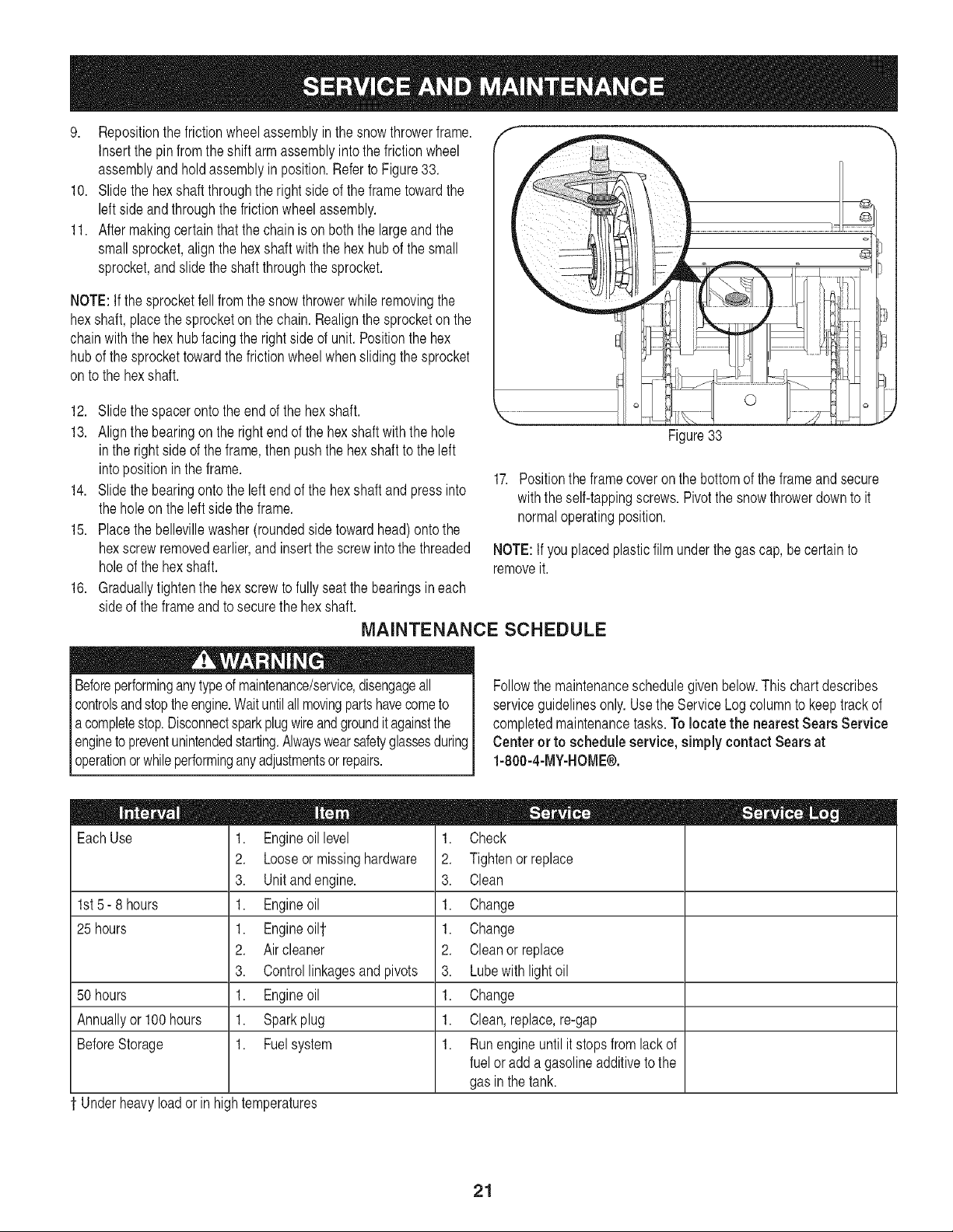
9. Repositionthe frictionwheelassemblyinthe snowthrowerframe.
Insertthe pinfromthe shiftarm assemblyintothe frictionwheel
assemblyandhold assemblyin position.Refer to Figure33.
10. Slide the hexshaftthroughthe right sideof the frame towardthe
leftside andthroughthe frictionwheelassembly.
11. After makingcertainthat the chainis on boththe largeand the
smallsprocket,align the hexshaft with the hexhub of the small
sprocket,and slidethe shaftthroughthesprocket.
NOTE:If thesprocketfellfromthe snowthrowerwhile removingthe
hexshaft,placethe sprocketon thechain.Realignthe sprocketon the
chainwiththe hex hubfacingthe rightsideof unit. Positionthe hex
hubof the sprockettowardthe frictionwheelwhenslidingthe sprocket
onto the hexshaft.
12. Slidethe spaceronto theend of the hexshaft.
13. Alignthe bearingon the rightend of the hexshaftwith the hole
in the rightside of theframe,then pushthe hexshaftto the left
intopositionin the frame.
14. Slidethe bearingontothe left endof the hexshaftand pressinto
the holeon the left side the frame.
15. Placethebellevillewasher (roundedsidetowardhead) ontothe
hexscrew removedearlier,and insertthe screwintothe threaded
holeof the hexshaft.
16. Graduallytightenthe hex screwto fullyseatthe bearingsineach
sideof theframeand to securethe hexshaft.
©
Figure33
17. Positionthe framecoveron thebottomof the frameand secure
withthe self-tappingscrews.Pivotthe snowthrowerdownto it
normaloperatingposition.
NOTE:Ifyou placedplasticfilmunderthe gascap, be certain to
removeit.
MAINTENANCE SCHEDULE
Beforeperforminganytypeof maintenance/service,disengageall
controlsand stoptheengine.Waituntilallmovingpartshavecometo
acompletestop.Disconnectsparkplugwireandgroundit againstthe
enginetopreventunintendedstarting.Alwayswearsafetyglassesduring
operationor whileperforminganyadjustmentsor repairs.
Followthe maintenanceschedulegivenbelow.This chart describes
serviceguidelinesonly.Use the ServiceLog columnto keeptrackof
completedmaintenancetasks.To locate the nearest Sears Service
Center or to schedule service, simply contactSears at
1-800-4-MY-HOME®.
EachUse
1st5- 8 hours
25 hours
50 hours
Annuallyor 100hours
BeforeStorage
' Underheavyloador inhightemperatures
1. Engineoil level
2. Looseor missinghardware
3. Unit and engine.
1. Engineoil
1. Engineoi11
2. Air cleaner
3. Controllinkagesand pivots
1. Engineoil
1. Sparkplug
1. Fuelsystem
1. Check
2. Tightenor replace
3. Clean
1. Change
1. Change
2. Cleanor replace
3. Lubewithlightoil
1. Change
1. Clean, replace,re-gap
1. Runengineuntil it stopsfrom lackof
fuel oradd agasolineadditiveto the
gas in thetank.
21
If the snowthrowerwill notbe usedfor 30daysor longer,or if it is the endof the snowseasonwhenthe lastpossibilityof snowisgone,the
equipmentneedsto be stored properly.Followstorageinstructionsbelowto ensuretop performancefromthe snowthrowerfor manymoreyears.
PREPARING ENGINE
Short=Term Storage
It is importantto preventgumdepositsfromforminginessentialfuel
systempartsof the enginesuch as the carburetor,fuel filter,fuel hose,
ortankduringshort-termstorage(15-30days).To preventthis,treat
the fuelsystemusingafuel stabilizer.
Fuelstabilizer(suchas STA-BILTM or ULTRA-FRESHTM) is an accept-
ablealternativein minimizingthe formationof fuelgum depositsduring
storage.Add stabilizerto gasolinein fueltank or storagecontainer.
Alwaysfollowmix ratiofoundon stabilizercontainer.Runengine at
least10 minutesafter addingstabilizerto allowit to reachthe carbure-
tor.
Neverstoresnowthrowerwith fuel in tankindoorsor in poorlyventi-
latedareas,wherefuelfumesmayreachan openflame,spark or pilo
ght as on afurnace,waterheater,clothesdryer orgas appliance.
PREPARING SNOW THROWER
,, Whenstoringthe snowthrowerin anunventilatedor metalstor-
ageshed, careshouldbe taken to rustproofthe equipment.Using
a light oilor silicone,coatthe equipment,especiallyanychains,
springs,bearingsand cables.
,, Removealldirt fromexteriorof engineand equipment.
,, Followlubricationrecommendations.
,, Storeequipmentin a clean,dry area.
Alcoholblendedfuels (calledgasoholor usingethanolor methanol)
canattractmoisturewhich leadsto separationand formationof acids
duringstorage.Acidicgas can damagethe fuelsystemof an engine
[wh e n storage.
Long=Term Storage
Toavoidengineproblems,thefuel systemshouldbe emptiedbefore
storagefor 30daysor longer.
Fuelleft inengineduringwarmweatherdeterioratesand will cause
seriousstartingproblems.
J
1. Runthe engineuntil thefuel tank is emptyand it stops due to lack
of fuel.Do notattemptto pourfuel fromthe engine.
pNeveruseengineor cleaningproducts or
/
carburetor inthe fueltank
ermanentdamagemayoccur, j
2. Removethe sparkplugandpourone (1)ounceof engineoil
throughthe sparkplug holeintothe cylinder.Coverspark plug hole
witha ragandcrankthe engineseveraltimesto distributethe oil.
Replacesparkplug.
22
Beforeperforminganytypeof maintenance/service,disengageall
controlsandstoptheengine.Waituntilallmovingpartshavecometo
a completestop.Disconnectsparkplugwireandgrounditagainstthe
engineto preventunintendedstarting.Alwayswearsafetyglassesdurin(
operationor whileperforminganyadjustmentsorrepairs.
Thissectionaddressesminor service issues,To locatethe nearestSears Service Center or to scheduleservice,simply contactSears
at 1-800-4-MY-HOME®.
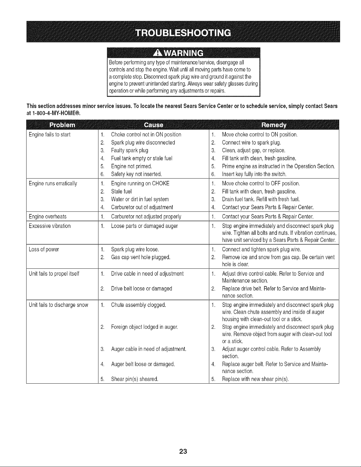
Enginefailsto start
o =
1. Chokecontrolnot in ONposition
2. Sparkplug wiredisconnected
3. Faultyspark plug
4. Fueltank emptyor stale fuel
5. Enginenot primed.
6. Safetykey not inserted.
1. Enginerunningon CHOKE
2. Stalefuel
3. Wateror dirt in fuel system
4. Carburetoroutof adjustment
1. Carburetornotadjustedproperly
1. Looseparts or damagedauger
Enginerunserratically
Engineoverheats
Excessivevibration
Lossof power 1. Sparkplug wireloose.
2. Gas capvent hole plugged.
Unitfailsto propelitself 1. Drive cablein needof adjustment
2. Drive belt looseor damaged
Unitfailsto dischargesnow 1. Chuteassemblyclogged.
2. Foreignobject lodged in auger.
3. Augercable in need of adjustment.
4. Augerbelt looseor damaged.
5. Shearpin(s) sheared.
1. Movechoke controlto ON position.
2. Connectwire to spark plug.
3. Clean,adjust gap,or replace.
4. Fill tank with clean,fresh gasoline.
5. Primeengineas instructedin the OperationSection.
6. Insert keyfully intothe switch.
1. Movechoke controlto OFF position.
2. Fill tank with clean,fresh gasoline.
3. Drainfuel tank.Refillwith freshfuel.
4. ContactyourSearsParts & RepairCenter.
1. ContactyourSearsParts & RepairCenter.
1. Stopengine immediatelyand disconnectspark plug
wire.Tightenall boltsandnuts.If vibrationcontinues,
haveunit servicedby a SearsParts& RepairCenter.
1. Connectand tighten sparkplug wire.
2. Removeice and snowfrom gas cap. Be certainvent
holeis clear.
1. Adjustdrivecontrolcable. Referto Serviceand
Maintenancesection.
2. Replacedrivebelt. Referto Serviceand Mainte-
nancesection.
1. Stopengine immediatelyand disconnectspark plug
wire.Cleanchuteassemblyand insideof auger
housingwith clean-outtool or a stick.
2. Stopengine immediatelyand disconnectspark plug
wire.Removeobject from augerwith clean-outtool
or a stick.
3. Adjustauger controlcable.Referto Assembly
section.
4. Replaceaugerbelt. Referto ServiceandMainte-
nancesection.
5. Replacewith newshearpin(s).
23
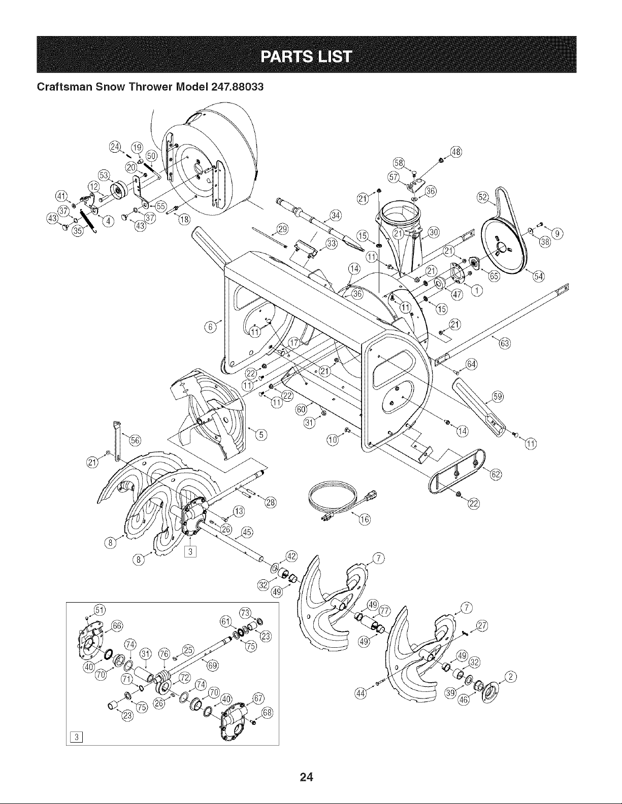
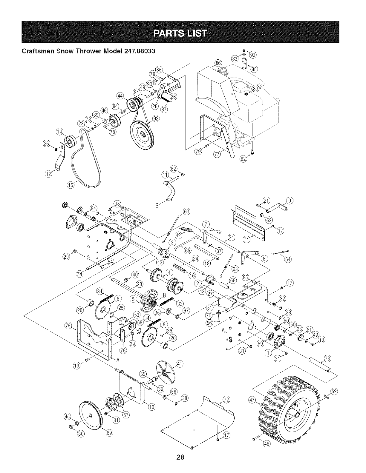
Craftsman Snow Thrower Model 247.88033
[]
24
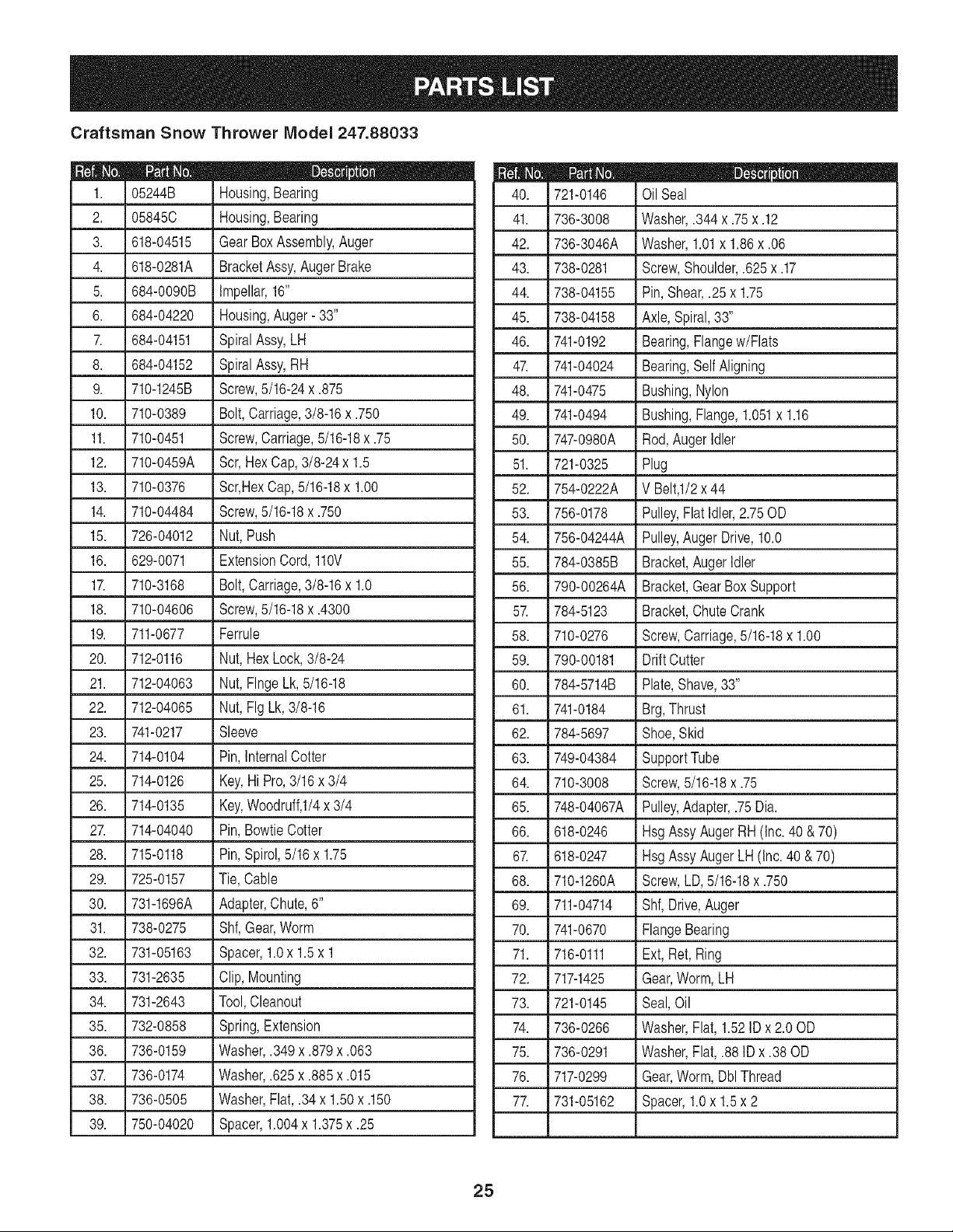
Craftsman Snow Thrower Model 247.88033
D" Q e
05244B Housing,Bearing
2. 05845C Housing,Bearing
3. 618-04515 Gear BoxAssembly,Auger
4. 618-0281A BracketAssy,Auger Brake
5. 684-0090B Impellar,16"
6. 684-04220 Housing,Auger- 33"
7. 684-04151 SpiralAssy,LH
8. 684-04152 SpiralAssy,RH
9. 710-1245B Screw,5/16-24x .875
10. 710-0389 Bolt,Carriage,3/8-16x .750
11. 710-0451 Screw,Carriage,5/16-18x .75
12. 710-0459A Scr,HexCap,3/8-24 x 1.5
13. 710-0376 Scr,HexCap, 5/16-18x 1.00
14. 710-04484 Screw,5/16-18x .750
15. 726-04012 Nut,Push
16. 629-0071 ExtensionCord,110V
17. 710-3168 Bolt,Carriage,3/8-16x 1.0
18. 710-04606 Screw,5/16-18x .4300
19. 711-0677 Ferrule
20. 712-0116 Nut,Hex Lock,3/8-24
21. 712-04063 Nut,FlngeLk,5/16-18
22. 712-04065 Nut,Fig Lk,3/8-16
23. 741-0217 Sleeve
24. 714-0104 Pin,InternalCotter
25. 714-0126 Key,Hi Pro,3/16x 3/4
26. 714-0135 Key,Woodruff,I/4x 3/4
27. 714-04040 Pin,BowtieCotter
28. 715-0118 Pin,Spirol,5/16 x 1.75
29. 725-0157 Tie,Cable
30. 731-1696A Adapter,Chute,6"
31. 738-0275 Shf,Gear,Worm
32. 731-05163 Spacer,1.0x 1.5x 1
33. 731-2635 Clip,Mounting
34. 731-2643 Tool,Cleanout
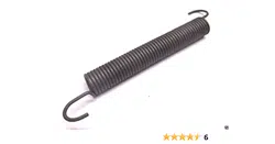
35. 732-0858 Spring,Extension
36. 736-0159 Washer,.349x .879x .063
37. 736-0174 Washer,.625x .885x .015
38. 736-0505 Washer,Flat,.34 x 1.50x .150
39. 750-04020 Spacer,1.004x 1.375x .25
721-0146 Oil Seal
41. 736-3008 Washer,.344 x .75x .12
42. 736-3046A Washer,1.01x 1.86x .06
43. 738-0281 Screw,Shoulder,.625 x .17
44. 738-04155 Pin, Shear,.25x 1.75
45. 738-04158 Axle,Spiral,33"
46. 741-0192 Bearing,Flangew/Flats
47. 741-04024 Bearing,SelfAligning
48. 741-0475 Bushing,Nylon
49. 741-0494 Bushing,Flange,1.051x 1.16
50. 747-0980A Rod,AugerIdler
51. 721-0325 Plug
52. 754-0222A V Belt,l/2 x 44
53. 756-0178 Pulley,Flat Idler,2.75OD
54. 756-04244A Pulley,AugerDrive,10.0
55. 784-0385B Bracket,AugerIdler
56. 790-00264A Bracket,GearBox Support
57. 784-5123 Bracket,Chute Crank
58. 710-0276 Screw,Carriage,5/16-18x 1.00
59. 790-00181 DriftCutter
60. 784-5714B Plate,Shave,33"
61. 741-0184 Brg,Thrust
62. 784-5697 Shoe,Skid
63. 749-04384 SupportTube
64. 710-3008 Screw,5/16-18x .75
65. 748-04067A Pulley,Adapter,.75Dia.
66. 618-0246 Hsg AssyAuger RH (Inc.40 & 70)
67. 618-0247 HsgAssyAugerLH(Inc. 40& 70)
68. 710-1260A Screw,LD,5/16-18x .750
69. 711-04714 Shf,Drive,Auger
70. 741-0670 FlangeBearing
71. 716-0111 Ext, Ret,Ring
72. 717-1425 Gear,Worm,LH
73. 721-0145 Seal,Oil
74. 736-0266 Washer,Flat, 1.52IDx 2.00D
75. 736-0291 Washer,Flat, .88 IDx .38 OD
76. 717-0299 Gear,Worm,DblThread
77. 731-05162 Spacer,1.0x 1.5x 2
25
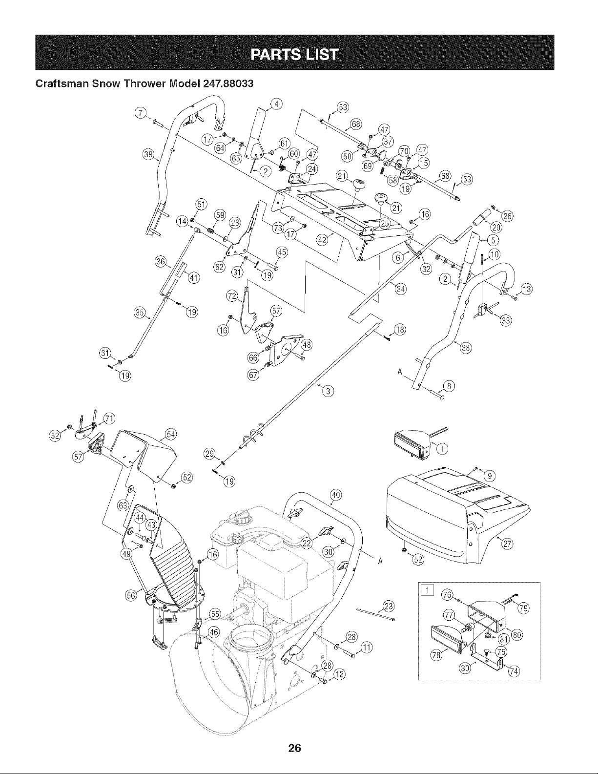
Craftsman Snow Thrower Model 247.88033
®
\
26
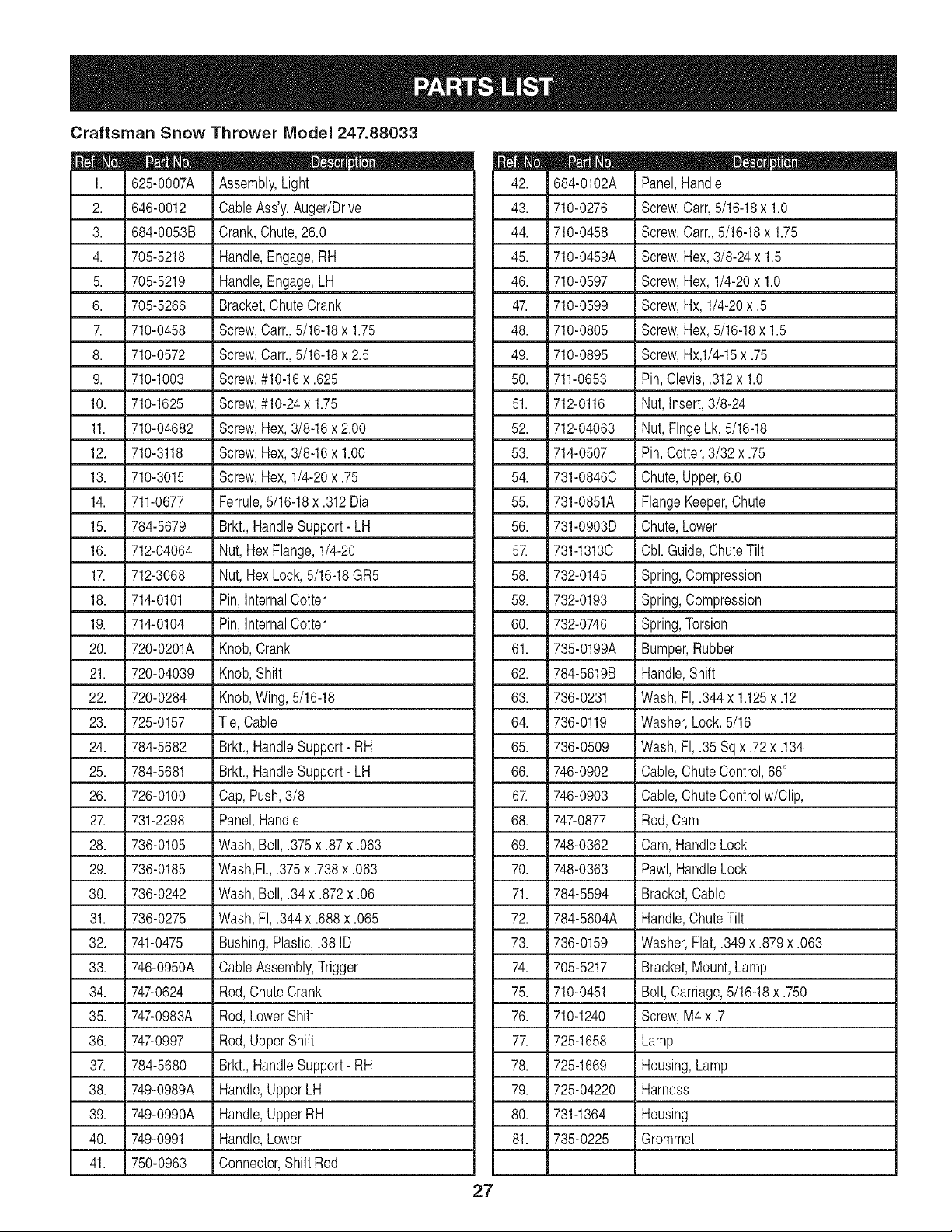
Craftsman Snow Thrower Model 247.88033
D" i Q
625-0007A Assembly,Light
2. 646-0012 CableAss'y,Auger/Drive
3. 684-0053B Crank,Chute,26.0
4. 705-5218 Handle,Engage,RH
5. 705-5219 Handle,Engage,LH
6. 705-5266 Bracket,ChuteCrank
7. 710-0458 Screw,Cam, 5/16-18x 1.75
8. 710-0572 Screw,Cam, 5/16-18x 2.5
9. 710-1003 Screw,#10-16x .625
10. 710-1625 Screw,#10-24x 1.75
11. 710-04682 Screw,Hex,3/8-16x 2.00
12. 710-3118 Screw,Hex,3/8-16x 1.00
13. 710-3015 Screw,Hex,1/4-20x .75
14. 711-0677 Ferrule,5/16-18x .312Dia
15. 784-5679 Brkt.,HandleSupport- LH
16. 712-04064 Nut,Hex Flange,1/4-20
17. 712-3068 Nut,HexLock,5/16-18GR5
18. 714-0101 Pin,InternalCotter
19. 714-0104 Pin,InternalCotter
20. 720-0201A Knob,Crank
21. 720-04039 Knob,Shift
22. 720-0284 Knob,Wing, 5/16-18
23. 725-0157 Tie,Cable
24. 784-5682 Brkt., HandleSupport- RH
25. 784-5681 Brkt., HandleSupport- LH
26. 726-0100 Cap,Push,3/8
27. 731-2298 Panel,Handle
28. 736-0105 Wash,Bell,.375x .87x .063
29. 736-0185 Wash,Fl.,.375x .738x .063
30. 736-0242 Wash,Bell,.34 x .872x .06
31. 736-0275 Wash,FI,.344 x .688x .065
32. 741-0475 Bushing,Plastic,.38 ID
33. 746-0950A CableAssembly,Trigger
34. 747-0624 Rod,ChuteCrank
35. 747-0983A Rod,LowerShift
36. 747-0997 Rod,UpperShift
37. 784-5680 Brkt., HandleSupport- RH
38. 749-0989A Handle,UpperLH
39. 749-0990A Handle,UpperRH
40. 749-0991 Handle,Lower
41. 750-0963 Connector,ShiftRod
D _ O Q
684-0102A Panel,Handle
43. 710-0276 Screw,Carr,5/16-18x 1.0
44. 710-0458 Screw,Carr.,5/16-18x 1.75
45. 710-0459A Screw,Hex,3/8-24x 1.5
46. 710-0597 Screw,Hex, 1/4-20x 1.0
47. 710-0599 Screw,Hx, 1/4-20x .5
48. 710-0805 Screw,Hex,5/16-18x 1.5
49. 710-0895 Screw,Hx,1/4-15x .75
50. 711-0653 Pin,Clevis,.312x 1.0
51. 712-0116 Nut, Insert,3/8-24
52. 712-04063 Nut, FlngeLk,5/16-18
53. 714-0507 Pin,Cotter,3/32 x .75
54. 731-08460 Chute,Upper,6.0
55. 731-0851A FlangeKeeper,Chute
56. 731-0903D Chute,Lower
57. 731-13130 Cbl. Guide,ChuteTilt
58. 732-0145 Spring,Compression
59. 732-0193 Spring,Compression
60. 732-0746 Spring,Torsion
61. 735-0199A Bumper,Rubber
62. 784-5619B Handle,Shift
63. 736-0231 Wash,FI,.344x 1.125x .12
64. 736-0119 Washer,Lock,5/16
65. 736-0509 Wash,FI,.35 Sq x .72x .134
66. 746-0902 Cable,ChuteControl,66"
67. 746-0903 Cable,ChuteControlw/Clip,
68. 747-0877 Rod,Cam
69. 748-0362 Cam,HandleLock
70. 748-0363 Pawl,HandleLock
71. 784-5594 Bracket,Cable
72. 784-5604A Handle,ChuteTilt
73. 736-0159 Washer,Flat, .349x .879x .063
74. 705-5217 Bracket,Mount,Lamp
75. 710-0451 Bolt,Carriage,5/16-18x .750
76. 710-1240 Screw,M4 x .7
77. 725-1658 Lamp
78. 725-1669 Housing,Lamp
79. 725-04220 Harness
80. 731-1364 Housing
81. 735-0225 Grommet
27
28
Craftsman Snow Thrower Model 247.88033
I _ O Q
05244B Housing,Bearing
2. 618-0279 Dogg,SteeringDrive,LH
3. 618-0280 Dogg,SteeringDrive,RH
4. 618-0282E Shaft Assembly,Steering
5. 618-04178 Assembly,FrictionWheel
718-04034 Wheel,Friction,Bonded
710-0896 Screw,HexWash
6. 684-0118B Bracket,Auger Actuator
7. 684-0119B Bracket,DriveActuator
8. 684-04235 Sprocket,32T
9. 684-0161 Arm,Shift
10. 684-04212 Brkt, FrictionDrive Suprt.
11. 684-04103 RodAssembly,Shift
12. 784-0385B Brkt.,Idler,Auger
13. 710-0538 Screw,HexCap Lock,
14. 756-0178 Idler,Flat,2.75OD
15. 754-0222A V-Belt,1/2x 44.0
16. 750-04718 Spcr.,.51ID x 3.66Lg.
17. 710-1652 Screw,HexWash.
18. 750-04717 Spcr.,.51ID x 7.895Lg.
19. 710-3001 Screw,HexCap,3/8-16
20. 750-04703 Spcr.,1.0IDx 1.50OD
21. 710-0788 Screw,Hex,1/4-20x 1.00
22. 710-0459A Screw,3/8-24x 1.50
23. 711-04279 Shaft,HexDrive
24. 711-04605 Shaft,Actuator
25. 716-04048 Ring,Retainer
26. 712-0116 Nut, Hex InsertJam Lock
27. 712-0138 Nut, Hex,1/4-28GR5
28. 784-5726 Bracket,Idler,Drive
29. 712-04065 Nut, HxFlngeInsertLk
30. 712-0413 Nut, Hx InsertJam Lk
31. 710-04484 TT Screw,5/16-18x .750
32. 712-0717 Nut, Insert3/8-16
33. 713-0284 Chain,Endless,#41 x 36L
34. 713-0286 Chain,#420 x 40L
35. 713-04015 Sprocket,#41x lOT
36. 714-0135 Key,Woodruff
37. 714-0104 Pin, InternalCotter
D _ O i
716-0104 E-Ring
39. 714-0388 Key,Hi-Pro,3/16x 5/8
40. 716-0136 Ring,Retaining
41. 717-0302 Plate,Drive
42. 732-0121 Spring,Extension
43. 732-0209 Spring,Extension
44. 756-0241B Pulley,Dbl,3.25OD
45. 736-0158 Washer,Lock,5/8
46. 756-0240 Pulley,Flat Idler,3.00D
47. 634-0225A WheelAss'y.- LH
634-0226A WheelAss'y.- RH
734-2031 Tire
734-0255 Valve
741-0246A Bearing
48. 711-04615 Pin,Clevis
49. 736-0242 Wsh, Bell.,.34 x .872x .06
50. 736-0300 Wash,.406 x .875x .059
51. 736-0329 Washer,Lock, 1/4
52. 714-0149B Pin,InternalCotter
53. 737-3000 Fitting,Lube,3/16Drive
54. 738-0143 Screw,Shldr.,.498 x .34
55. 738-0279 Spindle,Drive Plate
56. 738-0924A Screw,HexShldr.,1/4-28
57. 741-0163A Ass'y, Bearing/Housing
58. 741-04108 Bearing,HexFlange
59. 741-04025 Bearing,SelfAligning
60. 741-04076 Bearing,Ball
61. 741-0563 Bearing,Ball
62. 741-0748 Bush,Fig, .5 ID x .627OD
63. 746-0949A Cable,Steering
64. 746-0951 Cable, AugerIdler
65. 747-0973 Rod, DriveClutch
66. 750-0903B Spcr.,.514x .632x 2.44
67. 750-0997 Spacer,.675x 1.0x .23
68. 750-1302B Spcr,.6725x 1.125x 2.48
69. 756-0344 Pulley,Drive
70. 756-0625 Roller,Cable
71. 790-00257 Cover,UpperFrame
72. 790-00259 Cover,LowerFrame
Continuedonfollowingpage
29
Craftsman Snow Thrower Model 247.88033
Continuedfrom previouspage
D" O 0
711-04607 Axle,Wheel,33"
74. 790-00255A Frame,Transmission
75. 784-0406A Bracket,FrameSupport
76. 784-0407 Bracket,Axle Support
77. 790-00254 Bracket,BeltCover
78. 710-0191 Screw,3/8-14x 1.25GR8
79. 710-0237 Screw,5/16-24x .625
80. 710-0607 Screw,Hx Wash HdTapp
81. 710-1245B Screw,HxCap 5/16-24
82. 710-0654A Screw,3/8-16x 1.00
83. 736-0173 Wsh,Flat,.28 x .74x .063
84. 714-0118 Key,Square,1/4 x 1.5
85. 790-00167A Brkt.,Belt, Keeper
86. 731-2531 Cover,Belt
87. 732-0303 Spring,Extension
88. 732-0705 Guide,Chute Cable
89. 736-0247 Washer,Flat, .406x 1.25
90. 748-0234 Spacer,Shoulder
91. 736-0159 Washer,Flat, .349x .879
92. 754-0131 V-Belt,3/8 x 35.5
93. 712-04064 Nut,Fig Lk, 1/4-20
94. 726-0221 Nut,Spd.
95. 735-04099 Plug,3/8 ID
30
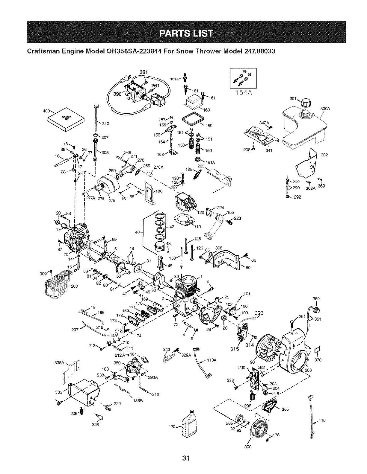
Craftsman Engine Model OH358SA-223844 For Snow Thrower Model 247.88033
154A
47
169,
335A,
186B
220 / / '''_" _" "
"._ _ ""-.206
328 420 ,.---" 92'
342A
/
990
i';
- 203
,178
300A
i _302
290 3_02A 369
35O
!
351
37O
31
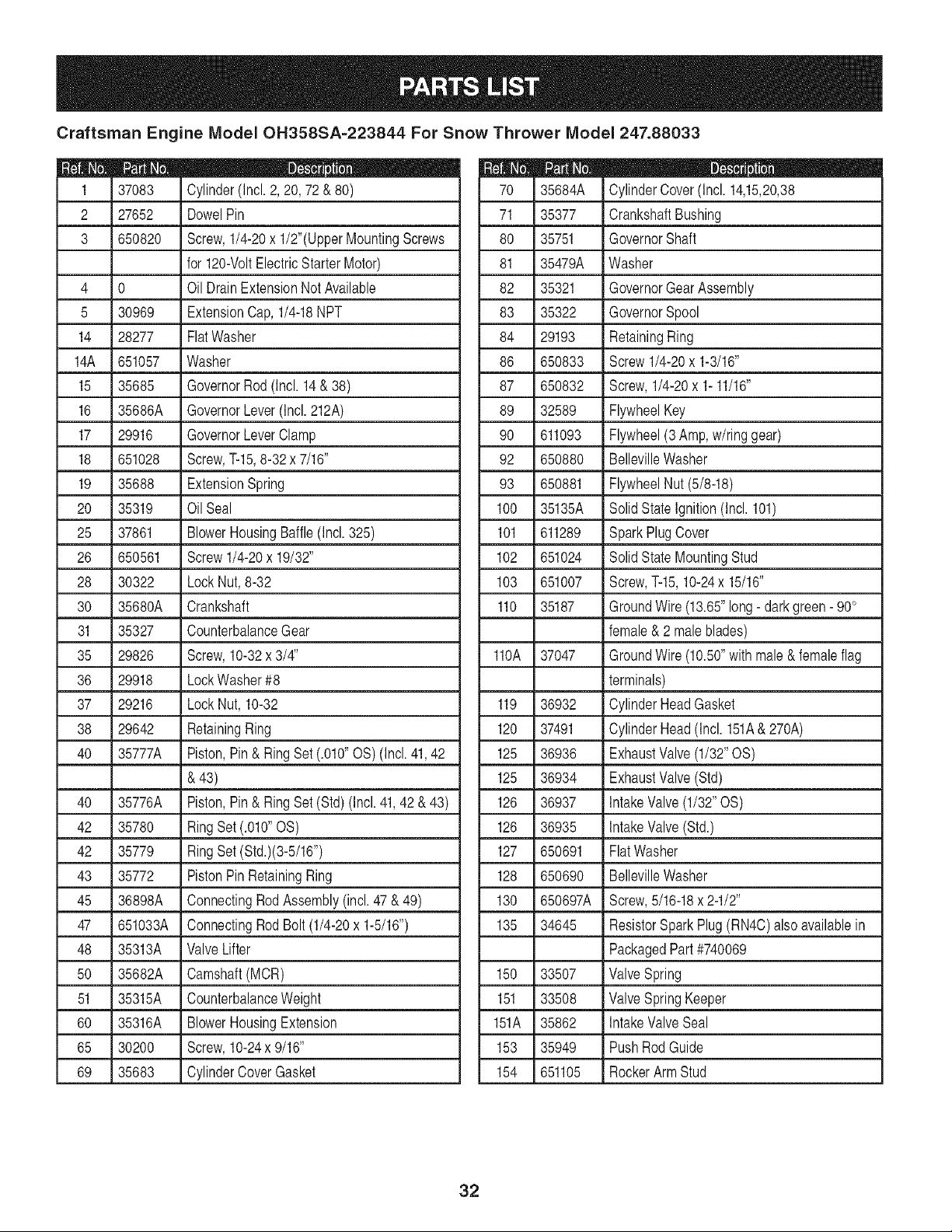
Craftsman Engine Model OH358SA=223844 For Snow Thrower Model 247.88033
37083
2 27652
3 650820
4 0
5 30969
14 28277
14A 651057
15 35685
16 35686A
17 29916
18 651028
19 35688
20 35319
25 37861
26 650561
28 30322
30 35680A
31 35327
35 29826
36 29918
37 29216
38 29642
40 35777A
40 35776A
42 35780
42 35779
43 35772
45 36898A
47 651033A
48 35313A
50 35682A
51 35315A
60 35316A
65 30200
69 35683
D _ J m
Cylinder(Incl.2, 20, 72& 80)
DowelPin
Screw,1/4-20x 1/2"(UpperMountingScrews
for 120-VoltElectricStarterMotor)
Oil DrainExtensionNotAvailable
ExtensionCap, 1/4-18NPT
FlatWasher
Washer
GovernorRod (Incl. 14& 38)
GovernorLever(Incl.212A)
GovernorLeverClamp
Screw,T-15,8-32x 7/16"
ExtensionSpring
Oil Seal
BlowerHousingBaffle(Incl.325)
Screw1/4-20x 19/32"
LockNut,8-32
Crankshaft
CounterbalanceGear
Screw,10-32x 3/4"
LockWasher#8
LockNut, 10-32
RetainingRing
Piston,Pin& Ring Set(.010"OS) (Incl.41,42
& 43)
Piston,Pin& Ring Set(Std) (Incl.41,42& 43)
RingSet (.010"OS)
RingSet (Std.)(3-5/16")
PistonPinRetainingRing
ConnectingRodAssembly(incl. 47 & 49)
ConnectingRodBolt (1/4-20x 1-5/16")
ValveLifter
Camshaft(MCR)
CounterbalanceWeight
BlowerHousingExtension
Screw,10-24x 9/16"
CylinderCoverGasket
35684A
71 35377
80 35751
81 35479A
82 35321
83 35322
84 29193
86 650833
87 650832
89 32589
90 611093
92 650880
93 650881
100 35135A
101 611289
102 651024
103 651007
110 35187
110A 37047
119 36932
120 37491
125 36936
125 36934
126 36937
126 36935
127 650691
128 650690
130 650697A
135 34645
150 33507
151 33508
151A 35862
153 35949
154 651105
D _ e ID
CylinderCover(Incl. 14,15,20,38
CrankshaftBushing
GovernorShaft
Washer
GovernorGearAssembly
GovernorSpool
RetainingRing
Screw1/4-20x 1-3/16"
Screw,1/4-20x 1- 11/16"
FlywheelKey
Flywheel(3Amp,w/ringgear)
BellevilleWasher
FlywheelNut(5/8-18)
SolidState Ignition(Incl. 101)
SparkPlugCover
SolidState MountingStud
Screw,T-15,10-24x 15/16"
GroundWire(13.65"long- darkgreen- 90°
female& 2 maleblades)
GroundWire(10.50"with male&femaleflag
terminals)
CylinderHeadGasket
CylinderHead(Incl. 151A&270A)
ExhaustValve(1/32"OS)
ExhaustValve(Std)
IntakeValve(1/32"OS)
IntakeValve(Std.)
FlatWasher
BellevilleWasher
Screw,5/16-18x 2-1/2"
ResistorSparkPlug(RN4C)also availablein
PackagedPart #740069
ValveSpring
ValveSpringKeeper
IntakeValveSeal
PushRod Guide
RockerArmStud
32
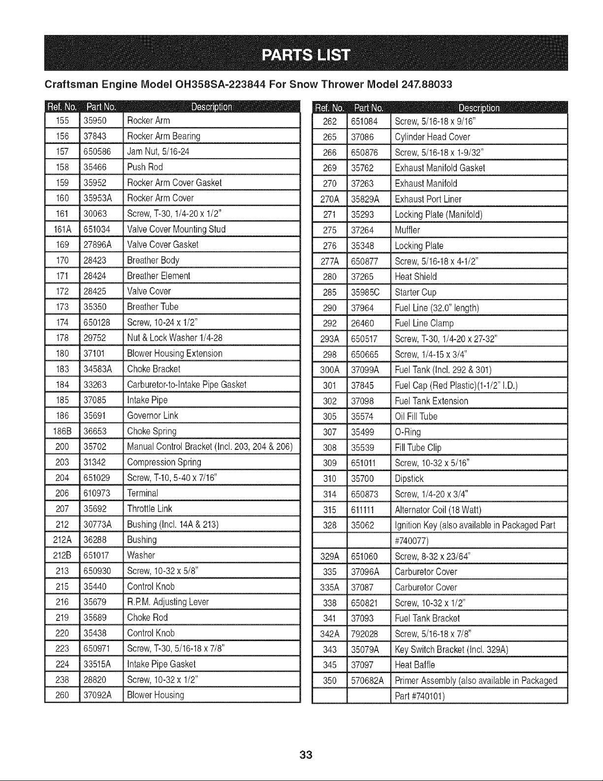
Craftsman Engine Model OH358SA=223844 For Snow Thrower Model 247.88033
D _ Q ®
35950 RockerArm
156 37843 RockerArm Bearing
157 650586 JamNut,5/16-24
158 35466 PushRod
159 35952 RockerArm CoverGasket
160 35953A RockerArm Cover
161 30063 Screw,T-30,1/4-20x 1/2"
161A 651034 ValveCoverMountingStud
169 27896A ValveCoverGasket
170 28423 BreatherBody
171 28424 BreatherElement
172 28425 ValveCover
173 35350 BreatherTube
174 650128 Screw,10-24x 1/2"
178 29752 Nut& LockWasher 1/4-28
180 37101 BlowerHousingExtension
183 34583A ChokeBracket
184 33263 Carburetor-to-IntakePipeGasket
185 37085 IntakePipe
186 35691 GovernorLink
186B 36653 ChokeSpring
200 35702 ManualControlBracket(Incl.203,204 &206)
203 31342 CompressionSpring
204 651029 Screw,T-IO,5-40 x 7/16"
206 610973 Terminal
207 35692 ThrottleLink
212 30773A Bushing(Incl. 14A& 213)
212A 36288 Bushing
212B 651017 Washer
213 650930 Screw,10-32x 5/8"
215 35440 ControlKnob
216 35679 R.RM.AdjustingLever
219 35689 ChokeRod
220 35438 ControlKnob
223 650971 Screw,T-30,5/16-18x 7/8"
224 33515A IntakePipeGasket
238 28820 Screw,10-32x 1/2"
260 37092A BlowerHousing
D _ O Q
651084 Screw,5/16-18x 9/16"
265 37086 CylinderHeadCover
266 650876 Screw,5/16-18x 1-9/32"
269 35762 ExhaustManifoldGasket
270 37263 ExhaustManifold
270A 35829A ExhaustPortLiner
271 35293 LockingPlate(Manifold)
275 37264 Muffler
276 35348 LockingPlate
277A 650877 Screw,5/16-18x 4-1/2"
280 37265 HeatShield
285 35985C StarterCup
290 37964 FuelLine(32.0"length)
292 26460 FuelLineClamp
293A 650517 Screw,T-30,1/4-20x 27-32"
298 650665 Screw,1/4-15x 3/4"
300A 37099A FuelTank(Incl.292&301)
301 37845 FuelCap(Red Plastic)(1-1/2"I.D.)
302 37098 FuelTankExtension
305 35574 Oil FillTube
307 35499 O-Ring
308 35539 FillTubeClip
309 651011 Screw,10-32x 5/16"
310 35700 Dipstick
314 650873 Screw,1/4-20x 3/4"
315 611111 AlternatorCoil (18Watt)
328 35062 IgnitionKey(alsoavailablein PackagedPart
#740077)
329A 651060 Screw,8-32x23/64"
335 37096A CarburetorCover
335A 37087 CarburetorCover
338 650821 Screw,10-32x 1/2"
341 37093 FuelTankBracket
342A 792028 Screw,5/16-18x 7/8"
343 35079A KeySwitchBracket(Incl.329A)
345 37097 HeatBaffle
350 570682A PrimerAssembly(alsoavailablein Packaged
Part#740101)
33
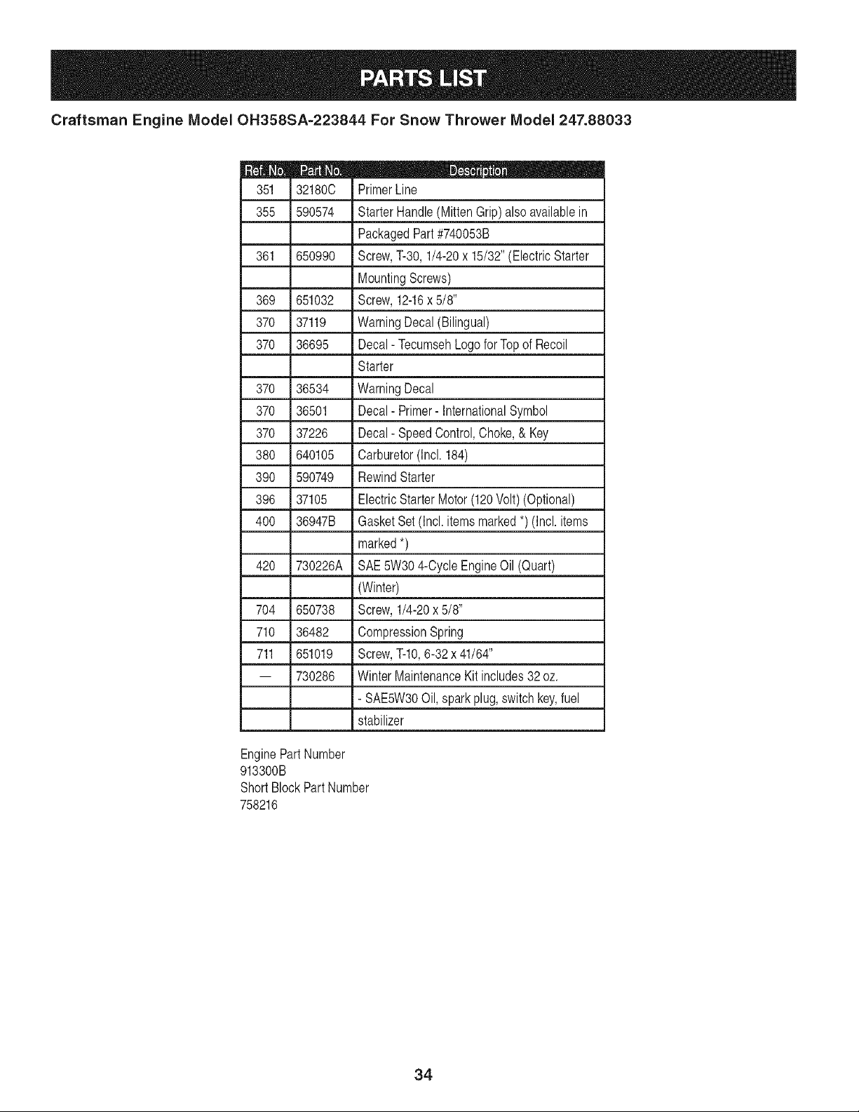
Craftsman Engine Model OH358SA-223844 For Snow Thrower Model 247.88033
32180C
355 590574
361 650990
369 651032
370 37119
370 36695
370
370
370
380
390
396
4OO
42O
36534
36501
37226
640105
590749
37105
36947B
730226A
704 650738
710 36482
711 651019
-- 730286
PrimerLine
StarterHandle(MittenGrip)alsoavailablein
PackagedPart#740053B
Screw,T-30,1/4-20x 15/32"(ElectricStarter
MountingScrews)
Screw,12-16x 5/8"
WarningDecal(Bilingual)
Decal- TecumsehLogofor Topof Recoil
Starter
WarningDecal
Decal- Primer-InternationalSymbol
Decal- SpeedControl,Choke,& Key
Carburetor(Incl.184)
RewindStarter
ElectricStarterMotor(120Volt)(Optional)
GasketSet (Incl.itemsmarked*) (Incl.items
marked*)
SAE5W304-CycleEngineOil (Quart)
(Winter)
Screw,1/4-20x 5/8"
CompressionSpring
Screw,T-IO,6-32 x 41/64"
WinterMaintenanceKit includes32 oz.
- SAE5W30Oil, sparkplug,switch key,fuel
stabilizer
EnginePartNumber
913300B
ShortBlockPartNumber
758216
34

35
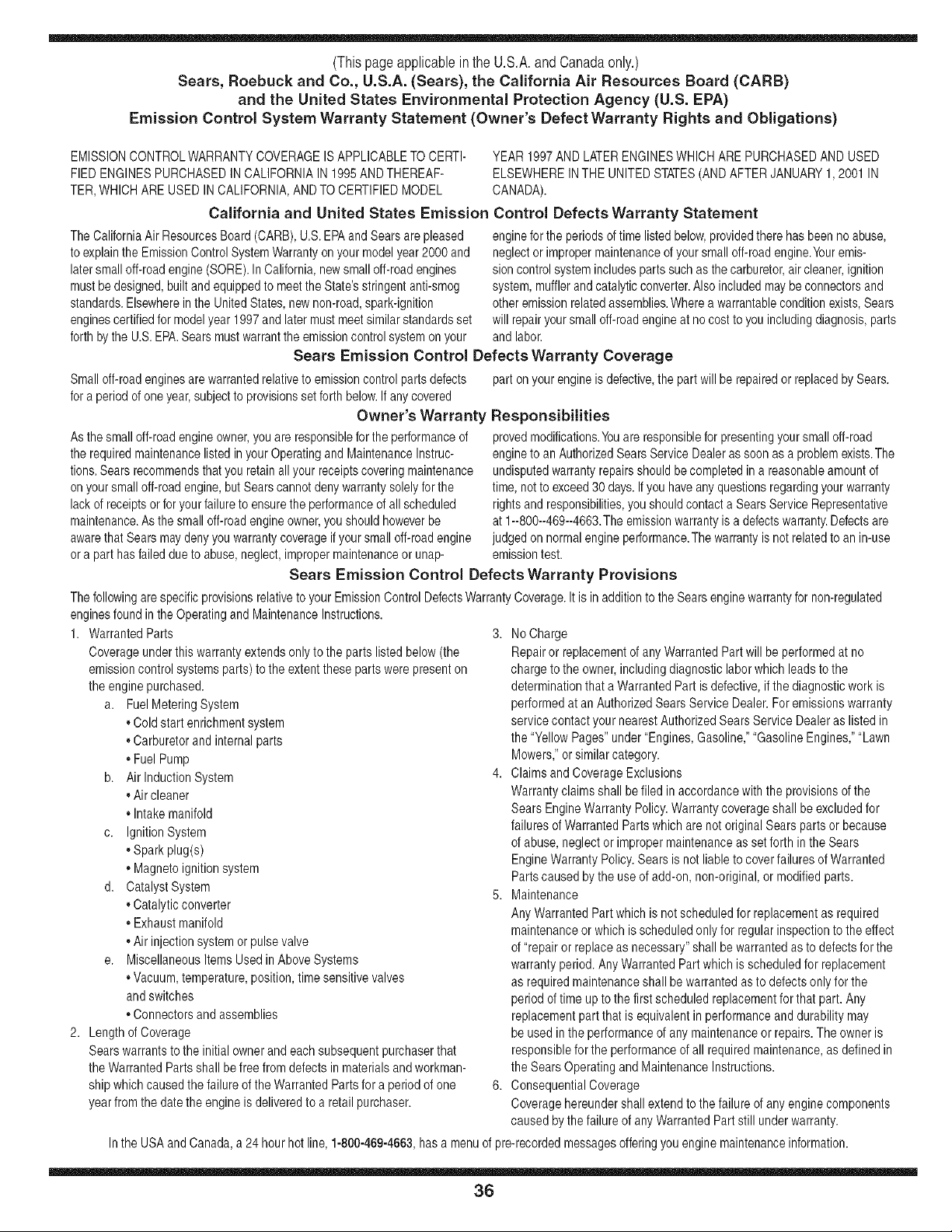
(Thispageapplicablein the U.S.A.and Canadaonly.)
Sears, Roebuck and Co., U.S.A. (Sears), the California Air Resources Board (CARB)
and the United States Environmental Protection Agency (U.S. EPA)
Emission ControJ System Warranty Statement (Owner's Defect Warranty Rights and ObJigations)
EMISSIONCONTROLWARRANTYCOVERAGEISAPPLICABLETO CERTI- YEAR 1997AND LATERENGINESWHICHARE PURCHASEDAND USED
FlED ENGINESPURCHASEDIN CALIFORNIAIN 1995ANDTHEREAF- ELSEWHEREINTHE UNITEDSTATES(ANDAFTERJANUARY1,2001 IN
TER,WHICHARE USED IN CALIFORNIA,ANDTO CERTIFIEDMODEL CANADA).
California and United States Emission Control Defects Warranty Statement
The CaliforniaAir ResourcesBoard(CARB),U.S.EPAandSearsare pleased
to explainthe EmissionControlSystemWarrantyon your modelyear2000 and
latersmalloff-roadengine(SORE).In California,newsmall off-roadengines
mustbe designed,builtand equippedto meetthe State'sstringentanti-smog
standards.Elsewhereinthe UnitedStates, newnon-road,spark-ignition
enginescertifiedfor modelyear 1997and latermustmeetsimilarstandardsset
forth bythe U.S.EPA.Sears mustwarranttheemissioncontrol systemonyour
enginefor the periodsof timelistedbelow,providedtherehas beenno abuse,
neglector impropermaintenanceof your smalloff-roadengine.Youremis-
sion controlsystemincludespartssuchas thecarburetor,air cleaner,ignition
system,mufflerand catalyticconverter.Also includedmaybe connectorsand
otheremissionrelatedassemblies.Wherea warrantableconditionexists,Sears
will repairyour smalloff-roadengine at no cost to youincludingdiagnosis,parts
and labor.
Sears Emission Control Defects Warranty Coverage
Smalloff-roadenginesarewarrantedrelativeto emissioncontrol partsdefects
fora period of oneyear,subjectto provisionsset forthbelow,Ifany covered
Owner's Warranty
Asthe smalloff-roadengineowner,you are responsiblefor theperformanceof
therequiredmaintenancelistedinyour Operatingand MaintenanceInstruc-
tions.Searsrecommendsthatyou retainall your receiptscoveringmaintenance
on yoursmall off-roadengine,butSearscannotdenywarrantysolelyforthe
lackof receiptsorfor yourfailureto ensurethe performanceof all scheduled
maintenance.Asthe smalloff-roadengineowner,you shouldhoweverbe
awarethat Sears maydenyyou warrantycoverageif your smalloff-roadengine
ora part hasfaileddueto abuse,neglect,impropermaintenanceor unap-
part onyour engineis defective,the part will be repairedor replacedbySears.
Responsibilities
provedmodifications.Youare responsiblefor presentingyour smalloff-road
engineto an AuthorizedSearsService Dealeras soonas a problemexists.The
undisputedwarrantyrepairsshouldbe completedin a reasonableamountof
time,not to exceed30 days.Ifyou haveany questionsregardingyour warranty
rightsand responsibilities,you shouldcontacta SearsServiceRepresentative
at 1--800--469--4663.Theemissionwarrantyis a defectswarranty.Defectsare
judgedon normalengineperformance.Thewarrantyis notrelatedto anin-use
emissiontest.
Sears Emission Control Defects Warranty Provisions
ThefollowingarespecificprovisionsrelativetoyourEmissionControlDefectsWarrantyCoverage.Itisinadditionto theSearsenginewarrantyfornon-regulated
enginesfoundin theOperatingandMaintenanceInstructions.
1. WarrantedParts
Coverageunderthis warrantyextendsonly to the parts listed below(the
emissioncontrol systemsparts)to the extentthese parts werepresenton
theengine purchased.
a. FuelMeteringSystem
,,Coldstart enrichmentsystem
,,Carburetorand internalparts
• FuelPump
b. Airlnduction System
,,Air cleaner
• Intakemanifold
c. IgnitionSystem
,,Sparkplug(s)
• Magnetoignitionsystem
d. CatalystSystem
,,Catalyticconverter
• Exhaustmanifold
,,Air injectionsystemor pulsevalve
e. MiscellaneousItemsUsed inAboveSystems
• Vacuum,temperature,position,timesensitive valves
andswitches
• Connectorsand assemblies
2. Lengthof Coverage
Searswarrantsto the initialownerand eachsubsequentpurchaserthat
theWarrantedParts shall befree from defectsin materialsandworkman-
ship whichcausedthe failureof the WarrantedPartsfor a periodof one
yearfromthe datethe engineis deliveredto a retailpurchaser.
3. NoCharge
Repairor replacementof any WarrantedPartwill be performedat no
chargeto the owner,includingdiagnosticlabor whichleadsto the
determinationthata WarrantedPartis defective,if the diagnosticwork is
performedat an AuthorizedSearsServiceDealer.For emissionswarranty
servicecontact your nearestAuthorizedSears ServiceDealeras listed in
the "YellowPages"under"Engines,Gasoline,""GasolineEngines,""Lawn
Mowers,"or similarcategory.
4. Claimsand CoverageExclusions
Warrantyclaimsshall be filed in accordancewiththe provisionsofthe
Sears EngineWarrantyPolicy.Warrantycoverageshall be excludedfor
failures of WarrantedPartswhichare not originalSears parts or because
of abuse,neglector impropermaintenanceas setforth in theSears
EngineWarrantyPolicy.Searsis not liable to coverfailuresof Warranted
Partscausedby the useof add-on,non-original,or modifiedparts.
5. Maintenance
Any WarrantedPartwhich is notscheduledfor replacementas required
maintenanceor which is scheduledonly for regularinspectionto the effect
of "repairor replaceas necessary"shall bewarrantedas to defectsfor the
warrantyperiod.Any WarrantedPartwhich is scheduledfor replacement
as requiredmaintenanceshallbe warrantedasto defectsonly for the
periodof time upto the first scheduledreplacementforthat part.Any
replacementpart that is equivalentin performanceand durabilitymay
be usedin theperformanceof any maintenanceor repairs.Theowneris
responsibleforthe performanceof all requiredmaintenance,as definedin
the SearsOperatingandMaintenanceInstructions.
6. ConsequentialCoverage
Coveragehereundershallextend to thefailure of any enginecomponents
caused bythefailure of anyWarrantedPartstill underwarranty.
Inthe USAand Canada,a 24 hour hot line, 1-800-469-4663,has a menuof pre-recordedmessagesofferingyou engine maintenanceinformation.
36
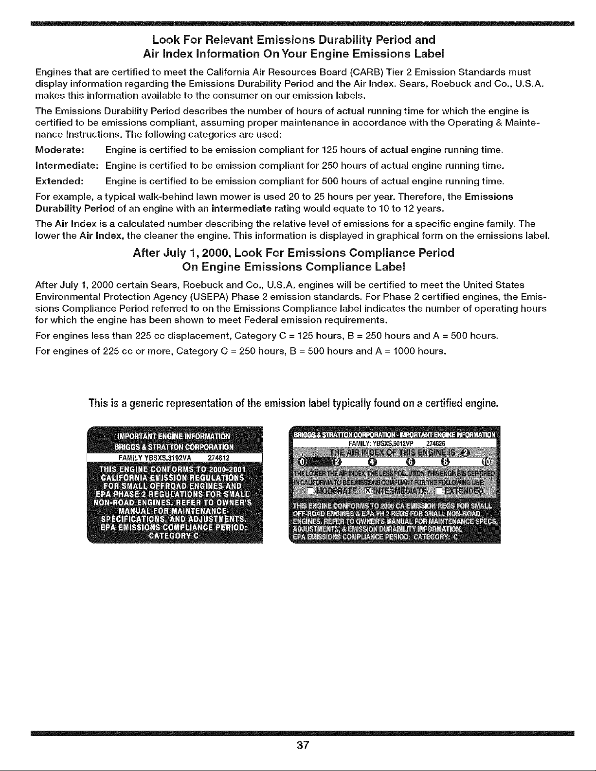
Look For Relevant Emissions Durability Period and
Air index information On Your Engine Emissions Label
Engines that are certified to meet the California Air Resources Board (CARB) Tier 2 Emission Standards must
display information regarding the Emissions Durability Period and the Air Index. Sears, Roebuck and Co., U.S.A.
makes this information available to the consumer on our emission labels.
The Emissions Durability Period describes the number of hours of actual running time for which the engine is
certified to be emissions compliant, assuming proper maintenance in accordance with the Operating & Mainte-
nance instructions. The following categories are used:
Moderate: Engine is certified to be emission compliant for 125 hours of actual engine running time.
intermediate: Engine is certified to be emission compliant for 250 hours of actual engine running time.
Extended: Engine is certified to be emission compliant for 500 hours of actual engine running time.
For example, a typical walk-behind lawn mower is used 20 to 25 hours per year. Therefore, the Emissions
Durability Period of an engine with an intermediate rating would equate to 10 to 12 years.
The Air index is a calculated number describing the relative level of emissions for a specific engine family. The
lower the Air index, the cleaner the engine. This information is displayed in graphical form on the emissions label.
After July 1,2000, Look For Emissions Compliance Period
On Engine Emissions Compliance Label
After July 1, 2000 certain Sears, Roebuck and Co., U.S.A. engines will be certified to meet the United States
Environmental Protection Agency (USEPA) Phase 2 emission standards. For Phase 2 certified engines, the Emis-
sions Compliance Period referred to on the Emissions Compliance label indicates the number of operating hours
for which the engine has been shown to meet Federal emission requirements.
For engines less than 225 cc displacement, Category C = 125 hours, B = 250 hours and A = 500 hours.
For engines of 225 cc or more, Category C = 250 hours, B = 500 hours and A = 1000 hours.
This is a generic representationof the emission labeltypically found on a certified engine.
37
Congratulationson makingasmartpurchase.YournewCraftsman®
Professionalproductis designedand manufacturedfor years of
dependableoperation.But likeallproducts,it mayrequirerepairfrom
timeto time.That'swhenhavinga RepairProtectionAgreementcan
saveyou moneyandaggravation.
Here'swhatthe RepairProtectionAgreement*includes:
,, Expertserviceby our 10,000professionalrepair specialists
,, Unlimitedserviceand no chargefor partsand labor on all covered
repairs
,, Productreplacementup to $1500if yourcoveredproductcan't be
fixed
,, Discountof 10%fromregularpriceof serviceand service-related
partsnotcoveredby the agreement;also, 10%off regularpriceof
preventivemaintenancecheck
,, Fasthelpby phone-we call it RapidResolution- phonesupport
froma Searsrepresentative.Think of usas a "talkingowner's
manual."
Onceyou purchasethe Agreement,a simplephonecall is all that it
takesfor you toscheduleservice.Youcan call anytimeday or night, or
schedulea serviceappointmentonline.
The RepairProtectionAgreementis a risk-freepurchase.If youcancel
for any reasonduringthe productwarrantyperiod,wewill providea full
refund.Or,a proratedrefundanytimeafterthe productwarrantyperiod
expires.PurchaseyourRepairProtectionAgreementtoday!
Some limitationsand exclusionsapply. For pricesand additional
informationin the U.S.A.call 1-800-827-8655.
*Coverage inCanadavaries on some items.Forfull details call
Sears Canada at 1-800-381-8665.
Sears Installation Service
ForSearsprofessionalinstallationof homeappliances,garagedoor
openers,waterheaters,and othermajorhomeitems,in the U.S.A.or
Canadacall 1-800-4-MY-HOME®.
38

Declaraci6n de garantia ............................ PAgina 39
PrActicas operaci6n seguras ..................... PAgina 40
Montaje ...................................................... PAgina 42
Operaci6n .................................................. PAgina 46
Servicio y Mantenimiento .......................... PAgina50
Almacenamiento fuera de temporada ....... PAgina 59
Soluci6n de problemas ............................. PAgina 60
Etiquetas de seguridad ............................. PAgina 5
Lista de piezas ........................................... PAgina 24
Acuerdo de protecci6n para reparaciones ... PAgina 63
NOmero de servicio Cubierta posterior
Garantia de dos a_os para la maquina quitanieve Craftsman
Esteequipoest,. cubiertopor una garanfiade dosahos, siempreque se mantenga,lubriquey ajustede acuerdocon las instruccionesdel
presentemanualdel operador.Duranteel aho de garanfia,si este equiposufrecualquierfalla producidapordefectosen materialeso manode
obra,DEVUELVALOA SUCENTRODE PARTES&REPARACIONSEARSM_,SCERCANO,y SearsIo reparar_tsin ningOncargo.El serviciode
garanfiaa domicilioesterdisponibleperose aplicar_tuncargode traslado.
Esta garantia no cubre:
• Elementosdesechablesquese desgastanporel usonormal,incluyendoentreotros,zapatasantideslizantes,placade raspadoy bujias.
Reparacionesnecesariasdebidoa negligenciadeloperador,incluyendoentreotros,dahosmecanicoy electricoocasionadopor un almace-
namientonoapropiado,abolladuracigOehal,falla por el usode aceitedegrado y/o cantidadno apropiadao fallaporno darmantenimiento
al equipodeacuerdocon las instruccionescontenidasenel manualdel operador.
Limpiezao reparacionesal motor(sistemadecombustible)provocadaspor un combustiblecontaminadouoxidado(viejo).Engeneral,el
combustibledebeutilizarseen un periodono mayorde 30 diasa partir desu adquisici6n.
Estagaranfias61otendr_tvalidezdurante90 dias si este productose utilizaen cualquiermomentoparafinescomercialeso dealquiler.
Estagaranfias61otendr_,validezmientrasel productose utiliceen los EstadosUnidos.
Estagaranfialeotorgaderechoslegalesespecificos,pero ustedpodria gozarde otros derechosen raz6nde su lugarde residencia.
Sears, Roebuck and Co., Hoffman Estates, IL 60179
Tipo deaceitedel motor:
Capacidadde aceitedel motor:
Capacidadde combustible:
Bujias:
Separaci6nde lasbujias:
SAE5W-30
28 onzas
4 cuartos
Champion@RJ19LM
.030"
N_merode modelo ..........................................................
Numerode serie ..............................................................
Fechade compra.............................................................
Registrearribael nOmerodel modelo,el nOmerode seriey la fecha
de compra
© Sears Brands,LLC
39
La presenciade estesimbolo indicaque setrata de
instruccionesimportantesde seguridadquese deben
respetarpara evitar poneren peligrosu seguridad
personaly/o materialy la de otraspersonas.Leay siga
todas las instruccionesde este manualantesde poner
en funcionamientoestamaquina.Si norespetaestasinstruccionespodria
provocarlesionespersonales.Cuandovea estesfmbolo,i presteatenciona
la advertencia!
Su responsabilidad: Restrinjael usodeesta m_tquinamotorizada
alas personasquelean,comprendany respetenlas advertenciase
instruccionesque aparecenen este manualyen la m_tquina.
Esta maquinafue construidapara ser operadade acuerdocon las reglas
de seguridadcontenidaseneste manual.AI igual quecon cualquiertipo
de equipo motorizado,un descuidoo error por parte del operadorpuede
producirlesionesgraves.Estamaquinaes capazde amputarmanosy pies
y dearrojar objetoscon granfuerza. Deno respetarlas instruccionesde
seguridadsiguientesse puedenproducirlesionesgraveso la muerte.
Elescape del motorde este producto,algunosde suscomponentesy
algunoscomponentesdel vehfculocontieneno liberansustanciasqdmicas
que elestado de Californiaconsideraquepuedenproducircancer,defectos
de nacimientou otros problemasreproductivos.
CAPACITACIAN
,, Lea,entienday cumplatodas las instruccionesincluidasen la maquina
yen los manualesantesde montarlay utilizarla.Guardeestemanual
en un lugarseguropara consultasfuturasy regulares,asf como para
solicitarrepuestos.
,, Familiarfcesecon todos loscontrolesy sufuncionamientoapropiado.
Sepacome detenerla maquinaycome desengranarlos controles
r@idamente.
,, No permitanuncaque losnihos menoresde 14ahosutilicen esta
maquina.Los ni_os de 14ahosy masmayoresdebenleery com-
prenderlas instruccionesde funcionamientoy las reglasde seguridad
contenidasen estemanual,y tambiendebenser capacitadosy estar
supervisadospor unode los padres.
,, Nunca permitaquelos adultosutilicen esta maquinasin recibirantes la
instruccionapropiada.
,, Los objetosarrojadospor lamaquinapuedenproducirlesionesgraves.
Planifiqueel patronen el queva air arrojandonieveparaevitar quela
descargade materialse realicehacialos caminos,los observadores,
etc.
,, Mantengaa los observadores,ayudantes,mascotasy ni_os perIo
menosa 75 piesde la maquinamientrasla mismaesta enfunciona-
miento.Detengala maquinasi alguienentraen lazona.
,, Seaprecavidoparaevitarpatinarseo caerseespecialmentecuando
operala maquinaen reversa.
PREPARATIVOS
,, InspeccioneminuciosamenteelAreadondeutilizaraelequipo.Saque
todoslosfelpudos,periAdicos,trineos,tablas,cablesy otrosobjetos
extraSoscon los quepodriatropezaro quepodrianserarrojadospor la
barrena/ motor.
,, Paraprotegerselos ojosutilice siempreanteojoso antiparrasde
seguridadmientrasopera la maquinao mientrasla ajustao repara.Los
objetos arrojadosque rebotanpuedenlesionargravementelavista.
,, Nooperela maquinasinla vestimentaadecuadapara estaral aire libre
en invierno.No utilicealhajas,bufandaslargasu otras prendassueltas
que podrianenredarseen laspartesmAviles.Utiliceun calzado especial
parasuperficiesresbaladizas.
,, Useun prolongadory untomacorrientede tres cablescon conexiAna
tierra paratodas las unidadescon motores deencendidoelectrico.
,, Ajustela alturade la caja del tomacorrienteparalimpiarla gravao las
superficiescon piedrastrituradas.
,, Desengranetodas laspalancas de controlantes de arrancarel motor.
,, Nuncaintenterealizarajustesmientrasel motorestaen marchaexcepto
en loscasos espedficamenterecomendadosen el manualdel operador.
,, Dejequeel motory la maquinaseadapten a latemperaturaexterior
antes de comenzara sacar lanieve.
,, ParaevitarlesionsepersonalesodaSosmaterialesseasumamentecuidadosoal
manipularlagasdina.Lagaselinaesaltamenteinflamableysusvaporespuedencausar
explosiones.SepuedelesionargravemsetesJderramagasdinasebreustedosebrela
ropayaquesepuedeprenderfuego.Laveselapiely camloiesederopadeinmediato.
,, Utilicesale recipientespara gasolinaautorizados.
,, Apaguetodosloscigarrillos,cigarros,pipasy otrasfuentesde combustion.
,, Nuncacarguecombustibleenla maquinaen un espaciocerrado.
,, Nuncasaque latapa del gas niagreguecombustiblemientrasel motor
estacaliente o en marcha.
,, Dejequeel motorse enfriepor Io menosdos minutosantesdevolvera
cargar combustible.
,, Nuncarecargueeltanque de combustible.Lleneel tanqueno masde
1/2pulgadaper debajode la basedel cuellodel filtropara dejar espacio
para la dilataciondel combustible.
,, Vuelvaa colocar latapa de lagasolinay ajustelabien.
,, Limpielagasolinaderramadasobre el motory el equipo.Trasladela
maquinaa otra zona. Espere5 minutosantesde encenderel motor.
,, Nuncaalmacenela maquinao el recipientede combustibleen un
espaciocerradodondehayafuego, chispaso luz piloto(porejemplo,
hornos,calentadoresdeagua, calefactores,secadoresde ropa,etc.).
,, Dejequela maquinase enfrie por Io menos5 minutosantes de
guardarla.
40
OPERACION
• No pongalas maneso los piescerca de las piezasrotatorias,en la caja
de labarrena/ motoro en el montajedel canalde descarga.Elcontacto
con las piezasrotatoriaspuedeproducirla amputaciondemanosy pies.
,, La palancade control de la barrena/ motores un dispositivode seguri-
dad. Nuncapase poralto su funcionamiento.De hacerlola operaci6nde
la maquinaes riesgosay puedeocasionarlesiones.
,, Laspalancasde controldebenfuncionarbienen ambasdireccionesy
regresarautomaticamentea laposicionde desengranecuandose las
suelta.
,, Nuncaoperelamaquinasifaltaunmontajedelcanalo sielmismoesta.dafiado.
Mantengatodoslosdispositivosdeseguridadensulugaryen funcionamiento.
,, Nunca enciendaun motoren espacioscerradoso en unazonacon poca
ventilacion.Elescapedel motorcontienemonoxidodecarbono,un gas
inodoroy letal.
,, No utilicela maquinabajo la influenciadel alcoholo lasdrogas.
,, El silenciadory el motorse calientany puedenproducirquemaduras.No
lostoque.
,, Seasumamenteprecavidocuandooperela maquinasobre una
superficiecon gravao cuandola cruce. Mantengasealertapor si se
presentanpeligros ocultoso transito.
,, Tengacuidado cuandocambiede direccion o cuandooperela maquina
en pendientes.
,, Planifiqueel patronen el queva air arrojandonieveparaevitar que
la descargade materialse produzcahacia lasventanas,lasparedes,
losautomoviles,etc.y evitar asi posiblesdaflosmaterialeso lesiones
producidaspor los rebotes.
,, Nunca dirija ladescarga hacialosniflos, los observadoresy las
mascotasni dejeque nadiese paredelantede la maquina.
,, Nosobrecarguela capacidadde la maquinatratandode sacar la nieve
muyra.pidamente.
,, Nunca opereestamaquinasin buenavisibilidado iluminaci6n.Siempre
debe estarsegurode queesta bienafirmadoy sostengabienlas
manijas.Camine,nuncacorra.
,, Corte lacorrientea la barrena/ motorcuandotransporte lamaquinao
cuandola mismanoesta en uso.
,, Nunca operela maquinaa alta velocidadde desplazamientosobre
superficiesresbaladizas.Mirehaciaabajoy haciaatras ytenga cuidado
cuandovayamarchaatra.s.
,, Si la maquinacomenzaraa vibrar de maneraanormal,detengael motor,
desconecteel cablede la bujfay pongalade maneraque hagamasa
contrael motor.Inspeccionela maquinaminuciosamentepara ver si
estadaflada. Reparetodos losdaflos antesdeencendery operarla
maquina.
,, Desengranetodas las palancasde control y detengael motorantesde
dejar la posicionde operacion(detrasde lasmanijas).Esperea que la
barrena/ motorse detengapor completeantes de destaparel montaje
del canalo realizarajustese inspecciones.
,, Nunca pongalasmanos en las aberturasde descargao de recoleccion.
Utilice siemprela herramientade limpiezaque se adjuntaparadestapar
la aberturade descarga. Nodestapeel montajedelcanal mientrasel
motorestaen funcionamiento.Antes de destaparlo,apagueel motory
permanezcadetrasde las manijashastaquetodas laspartes movilesse
hayandetenido.
,, Usesolo unionesy accesoriosaprobadosper elfabricante (perejemplo,
pesaspara las ruedas,cadenaspara los neumaticos,cannas, etc.).
,, Si se presentansituacionesque no esta.nprevistasen estemanual,sea
cuidadosoy useel sentidocomun.Contactecon su centrode servicio
Sears paraobtenerayuda.
MANTENIMIENTO Y ALMACENAMIENTO
,, Nuncamanipulelosdispositivosde seguridadde maneraimprudente.
Controleperi6dicamenteque funcionende formaadecuada.Remftasea
las seccionesde mantenimientoy ajustede este manual.
,, Antesde realizarlalimpieza,repararo revisarla maquina,desengrane
todas las palancasde controly detengaelmotor.Esperea que la bar-
rena/ motorse detengaporcomplete.Desconecteel cable de la bujia
y pongalodemanera quehaga masacontrael motorpara evitar quese
enciendade maneraaccidental.
,, Controlefrecuentementequetodos lospernosy tornillosesten bien
ajustadosparacomprobarque la maquinase encuentraen condiciones
segurasde funcionamiento.Asimismo,realiceuna inspecci6nvisual de
la maquinapara controlarsi la mismaesta daflada.
,, Nocambiela configuraci6ndel reguladordel motorni acelerede-
masiadoel mismo.El reguladorcontrolala velocidadmaximasegurade
operaciondel motor.
,, Lasplacasde raspadoylaszapatasantideslizantesqueseusanconlamaquina
quitanievesedesgastany sedafian.Paraprotegersuseguridad,verifique
frecuentementetodosloscomponentesy reemplacelossoloconpartesdelos
fabricantesdeequiposoriginales(OEM)."Lautilizaci6ndepiezasquenocum-
planconlasespecificacionesdeequiposoriginalespodrfatenercomeresultado
un rendimientoincorrecto,y ademaslaseguridadpodrfaestarcomprometida"
,, Reviselos controlesperiodicamenteparaverificarque engraneny
desengranenadecuadamentey ajustelossi es necesario.Consultela
seccionde ajustesen este manualdel operadorparaobtenerinstruc-
ciones.
,, Mantengao reemplacelas etiquetasde seguridad e instruccionessegt]n
sea necesario.
,, Respetelas normasreferentesa la disposicioncorrectay las reglamen-
tacionessobre gas, combustible,etc. paraprotegerel medioambiente.
,, Antesde almacenarla maquinaenciendalaunos minutesparasacarla
nieveque hayaquedadoenla mismay paraevitarasi que se congelela
barrena/ motor.
,, Nuncaalmacenela maquinao el recipientede combustibleen un
espaciocerradodondehayafuego,chispaso luzpiloto como por
ejemplo,calentadoresde agua,hornos,secadoresde ropa,etc.
,, Consultesiempreel manualde funcionamientopara conocerlasinstruc-
cionesadecuadaspara el almacenamientofuerade temporada.
No modifique el motor
Paraevitarlesionesgraveso la muerte,no modifiqueelmotorbajoninguna
circunstancia.Si cambialaconfiguraci6ndel reguladorel motorpuededescon-
trolarsey operara velocidadesinseguras.Nuncacambielaconfiguracionde
fabricadel reguladordel motor.
41
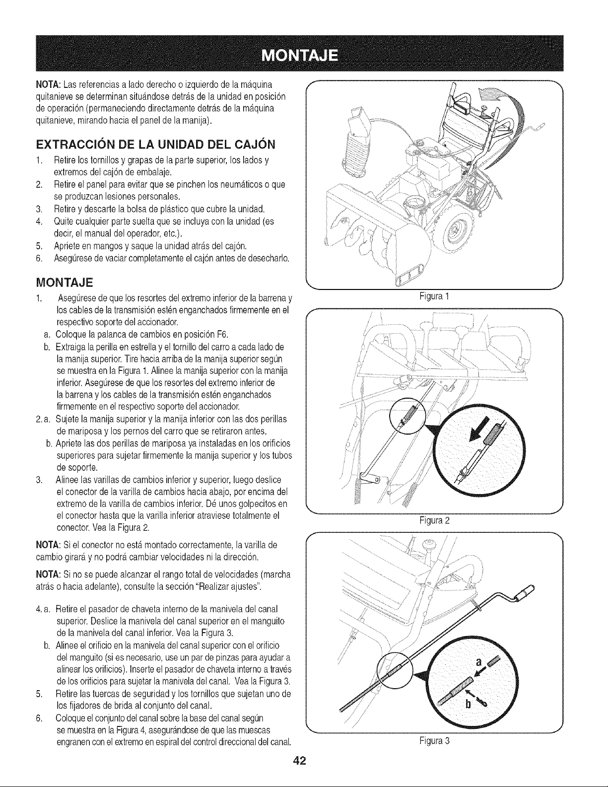
NOTA:Las referenciasa lado derechoo izquierdode la m_tquina
quitanievesedeterminansitu_mdosedetrasdela unidaden posici6n
deoperaci6n(permaneciendodirectamentedetr_.sde lam_tquina
quitanieve,mirandohaciael panelde la manija).
EXTRACCION DE LA UNIDAD DEL CAJON
1. Retirelos tornillosy grapasde la partesuperior,los ladosy
extremosdelcaj6n deembalaje.
2. Retireel panelpara evitarque sepinchenlos neum_tticoso que
se produzcanlesionespersonales.
3. Retirey descartela bolsa de pl_tsticoquecubre la unidad.
4. Quitecualquierpartesueltaque se incluyacon la unidad(es
decir,el manualdeloperador,etc.).
5. Aprieteen mangosy saquela unidadatr_tsdelcaj6n.
6. Aseg@esedevaciarcompletamenteel caj6nantesde desecharlo.
MONTAJE
1. Aseg0resedeque losresortesdel extremoinferiorde labarrenay
loscablesdela transmisi6nestenenganchadosfirmementeen el
respectivosoportedelaccionador.
a. Coloquela palancade cambiosen posici6nF6.
b. Extraigala perillaen estrellay el tornillodelcarroa cada ladode
lamanijasuperior.Tirehaciaarribadela manijasuperiorsegOn
se muestraen la Figura1.Alineela manijasuperiorcon lamanija
inferior.AsegOresedequelosresortesdel extremoinferiorde
labarrenay los cablesde latransmisi6nestenenganchados
firmementeenel respectivosoportedelaccionador.
2.a. Sujetela manijasuperiory la manijainferiorcon las dosperillas
de mariposay los pernosdelcarroquese retiraronantes.
b. Aprietelas dos perillasde mariposaya instaladasenlos orificios
superioresparasujetarfirmementela manijasuperiory los tubos
desoporte.
3. Alineelas varillasde cambiosinferiory superior,luegodeslice
elconectorde lavarilladecambioshaciaabajo,porencimadel
extremode lavarilladecambiosinferior.D6 unosgolpecitosen
elconectorhastaque lavarillainferioratraviesetotalmenteel
conector.Veala Figura2.
NOTA:Siel conectornoestermontadocorrectamente,la varillade
cambiogirarD,y nopodr_tcambiarvelocidadesni la direcci6n.
NOTA:Sinose puedealcanzarel rangototalde velocidades(marcha
atr_tso haciaadelante),consultela secci6n"Realizarajustes".
4.a. Retireel pasadorde chavetainternode la maniveladel canal
superior.Deslicelamaniveladel canalsuperiorenel manguito
de lamaniveladel canalinferior.Veala Figura3.
b. Alineeel orificioen la maniveladel canalsuperiorconel orificio
delmanguito(si es necesario,useun par de pinzasparaayudara
alinearlosorificios).Inserteel pasadorde chavetainternoa traves
delosorificiosparasujetarlamaniveladel canal. Veala Figura3.
5. Retirelas tuercasde seguridady los tornillosque sujetanunode
los fijadoresde bridaal conjuntodelcanal.
6. Coloqueelconjuntodel canalsobrelabasedelcanalsegOn
semuestraen la Figura4,asegur_.ndosede que lasmuescas
engranenconelextremoenespiraldelcontroldireccionaldel canal.
Figura1
/
/ .........
/
ii
J ii
f
Figura2
/
/
,/
/
Figura3
42
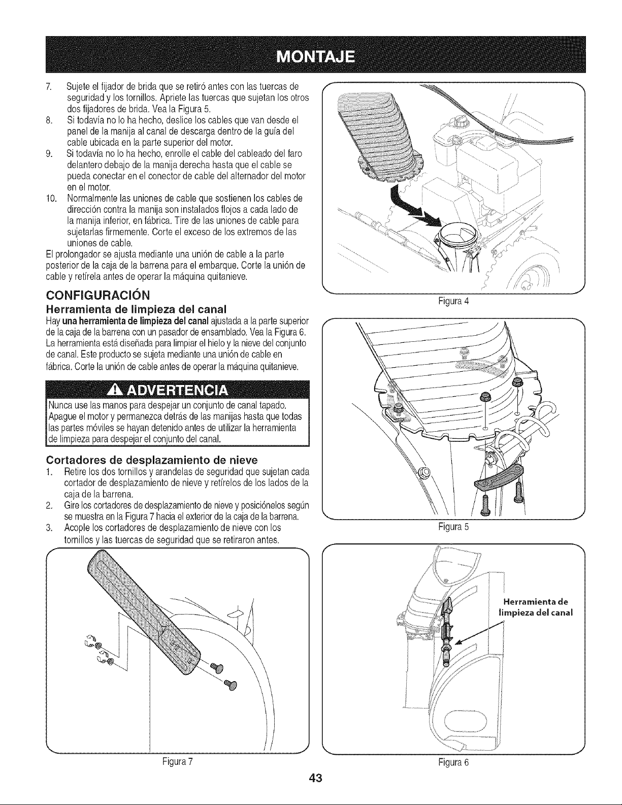
7. Sujeteel fijadorde bridaque se retir6antescon lastuercasde
seguridady los tornillos.Aprietelastuercasque sujetanlosotros
dosfijadoresde brida.Yeala Figura5.
8. Si todavianoIo hahecho,desliceloscablesque vandesdeel
panelde la manijaal canaldedescargadentrode la guiadel
cableubicadaen laparte superiordel motor.
9. Si todavia no Io ha hecho,enrolleel cabledel cableadodel faro
delanterodebajo de la manijaderechahastaque el cablese
puedaconectaren el conectordecabledelalternadordel motor
enel motor.
10. Normalmentelas unionesde cableque sostienenlos cablesde
direcci6ncontrala manijason instaladosflojos a cadalado de
la manijainferior,enfabrica.Tire de las unionesde cablepara
sujetarlasfirmemente.Corteel excesode losextremosde las
unionesde cable.
Elprolongadorse ajustamedianteunauni6nde cable a la parte
posteriorde lacaja de labarrenaparael embarque.Cortelauni6nde
cabley retirelaantesde operarla m_tquinaquitanieve.
CONFIGURACION
Herramienta de limpieza del canal
Hayuna herramientade limpiezadel canalajustadaa lapartesuperior
dela cajadela barrenaconun pasadorde ensamblado.Veala Figura6.
Laherramientaest,.disehadaparalimpiarel hieloy la nievedel conjunto
decanal.Esteproductose sujetamedianteuna uni6nde cableen
f_tbrica.Cortelauni6nde cableantesde operarla m_quinaquitanieve.
Nuncauselas manosparadespejarun conjuntode canaltapado.
Apagueel motory permanezcadetr_.sdelas manijashastaque todas
laspartesm6vilesse hayandetenidoantesde utilizarlaherramienta
de mpezaparadespeare conuntode cana.
Cortadores de desplazamiento de nieve
1. Retirelos dos tornillosy arandelasde seguridadque sujetancada
cortadordedesplazamientode nievey retirelosde los ladosde la
cajade la barrena.
2. Gireloscortadoresdedesplazamientode nievey posici6nelossegOn
se muestraen la Figura7 haciaelexteriorde lacajadelabarrena.
3. Acopleloscortadoresde desplazamientode nievecon los
tornillosy las tuercasde seguridadque se retiraronantes.
Figura4
\
Figura5
Hetramienta de
limpieza del canal
Figura7
43
Figura6
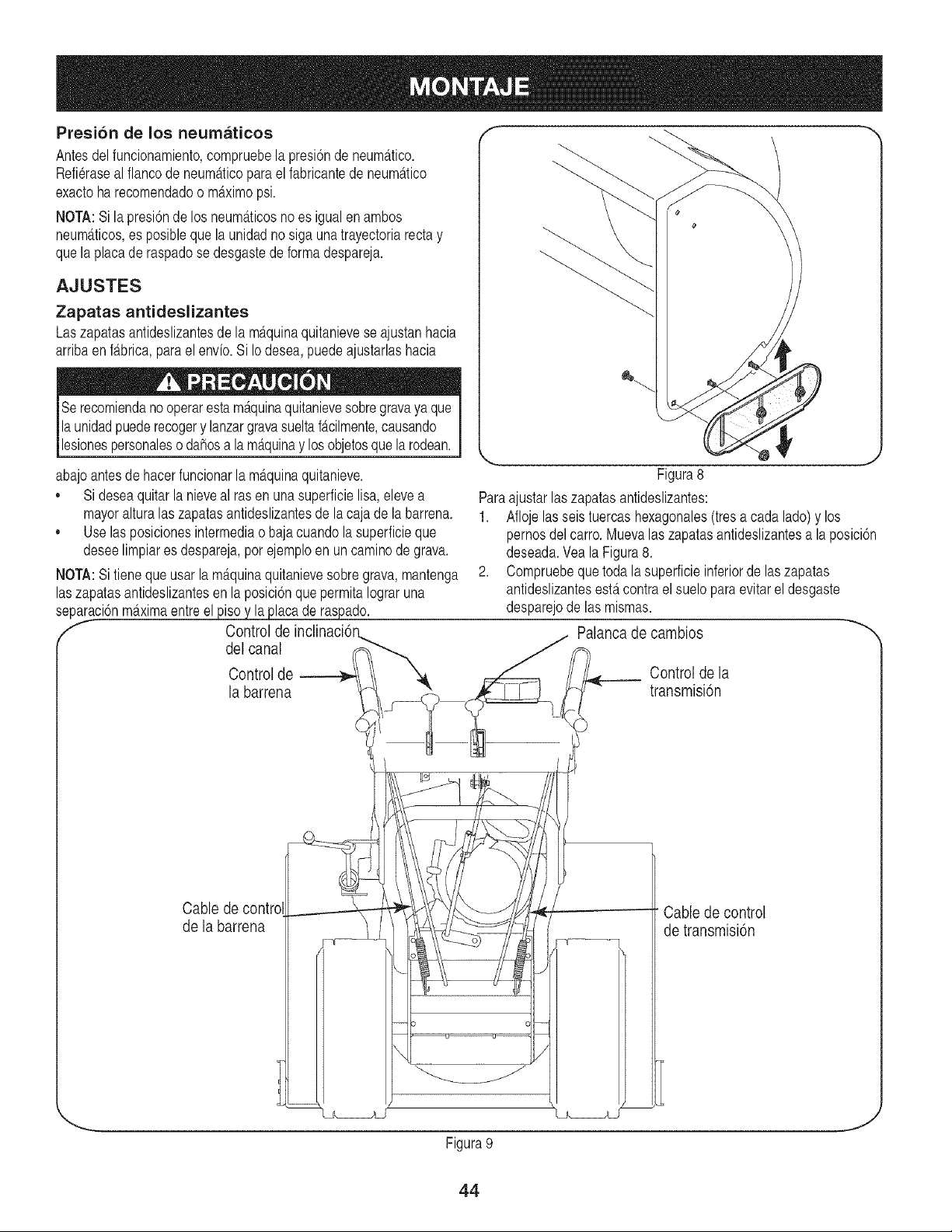
Presi6n de los neumaticos
Antesdelfuncionamiento,compruebelapresi6ndeneum_.tico.
Refieraseal flancode neum_.ticopara el fabricantede neum_ttico
exactoha recomendadoo m_tximopsi.
BIOTA:Si la presi6nde los neum_.ticosnoes igualenambos
neum_tticos,es posibleque la unidadno siga una trayectoriarectay
quela placade raspadose desgastede forma despareja.
AJUSTES
Zapatas antideslizantes
Laszapatasantideslizantesde la m_.quinaquitanievese ajustanhacia
arribaenf_tbrica,parael envio. Si Iodesea,puedeajustarlashacia
Serecomiendanooperaresta m_.quinaquitanievesobregravaya que
la unidadpuederecogery lanzargravasueltaf_.cilmente,causando
lesionespersonalesodahosa la m_tquinay losobjetosquela rodean.
abajoantesde hacerfuncionarla m_.quinaquitanieve.
,, Sideseaquitarla nieveal ras en una superficielisa,elevea
mayoralturalas zapatasantideslizantesde la caja de la barrena.
,, Uselasposicionesintermediaobajacuandolasuperficieque
deseelimpiares despareja,porejemploen uncaminode grava.
BIOTA:Si tieneque usar la m_.quinaquitanievesobregrava,mantenga
laszapatasantideslizantesen la posici6nquepermita Iograruna
separaci6nm_.ximaentreelpiso y la placade raspado.
f Control de
del canal
Control de
la barrena
Figura8
Paraajustarlas zapatasantideslizantes:
1. Afloje lasseis tuercashexagonales(tresa cada lado)y los
pernosdel carro. Muevalaszapatasantideslizantesa laposici6n
deseada.Veala Figura8.
2. Compruebeque toda la superficieinferiorde las zapatas
antideslizantesest,. contrael suelo paraevitarel desgaste
desparejode las mismas.
Palanca de cambios
Control de la
transmisi6n
Cable de control
de la barrena
Cable de control
de transmisi6n
Figura9
J
44
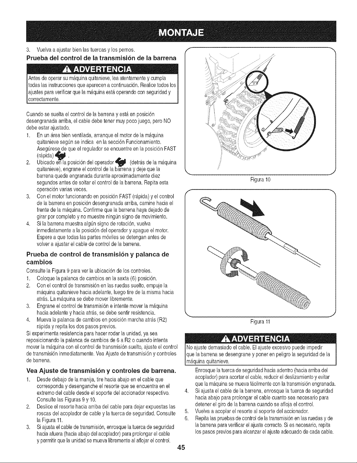
3. Vuelvaa ajustarbien las tuercasy lospernos.
Prueba del control de la transmision de la barrena
Antesdeoperarsu m_.quinaquitanieve,leaatentamentey cumpla
todaslas instruccionesque aparecenacontinuaci6n.Realicetodoslos
lajustesparaverificarque la m_tquinaesteroperandocon seguridady
|correctamente.
Cuandose suelta el controlde labarrenay est,.en posici6n
desengranadaarriba,el cabledebetener muypocojuego, peroNO
debeestarajustado.
1. En un _treabienventilada,arranqueel motorde la m_.quina
quitanievesegOnse indica en la secci6nFuncionamiento.
AsegOresedeque el reguladorse encuentreen laposici6nFAST
(r_tpida)_ .
2.
. . _T- .
Ublcadoenla poslcl6ndel operador (detr_.sde la m_tqulna
qultanleve),engraneel controlde la barrenay dejeque la
barrenaquedeengranadaduranteaproximadamentediez
segundosantesde soltarel controlde labarrena.Repitaesta
operaci6nvarias veces.
3. Conel motorfuncionandoen posici6nFAST(r_.pida)y el control
de labarrenaenposici6ndesengranadaarriba,caminehaciael
frentede la m_.quina.Confirmeque la barrenahayadejadode
girarporcompletoy no muestreningOnsignode movimiento.
4. Si la barrenamuestraalgOnsignode rotaci6n,vuelva
inmediatamentea la posici6ndel operadory apagueel motor.
Esperea quetodaslas partesm6vilesse detenganantesde
volvera ajustarelcable decontrolde la barrena.
Prueba de control de transrnision y palanca de
cambios
Consultela Figura9 paraver laubicaci6nde los controles.
1. Coloquela palancade cambiosen la sexta(6) posici6n.
2. Conel controlde transmisbnen las ruedassuelto,empujela
m_.quinaquitanievehaciaadelante,luegotire de la mismahacia
atr_ts.Lam_.quinase debemoverlibremente.
3. Engraneel controlde transmisi6ne intentemoverla m_.quina
haciaadelantey haciaatr_.s,se debesentirresistencia.
4. Muevala palancade cambiosen posici6nmarchaatr_ts(R2)
r_.piday repitalos dospasos previos.
Si experimentaresistenciapara hacerrodar la unidad,ya sea
reposicionandolapalancade cambiosde 6 aR2 o cuandointenta
moverla m_.quinacon el controldetransmisi6nsuelto,ajusteelcontrol
detransmisi6ninmediatamente.VeaAjustedetransmisi6ny controles
de barrena.
Yea Ajuste de transmisibn y controles de barrena.
1. Desdedebajode la manija,tire haciaabajo en el cableque
corresponday desengancheel resortequese encuentraen el
extremodel cable desdeel soportedelaccionadorrespectivo.
Consultelas Figuras9 y 10.
2. Desliceel resortehaciaarriba del cable paradejarexpuestaslas
roscasdelacopladorde cabley la tuercade seguridad.Consulte
la Figura11.
3. Si ajustael cablede transmisi6n,enrosquela tuercade seguridad
haciaafuera(haciaabajodel acoplador)paraprolongarel cable
y permitirquelaunidadse muevalibrementealaflojarel control.
f
Figura10
Figura11
No ajustedemasiadoel cable.El ajusteexcesivopuedeimpedir
que labarrenase desengraney poneren peligrola seguridadde la
m_tquinaquitanieve.
Enrosquela tuercade seguridadhaciaadentro(haciaarribadel
acoplador)para acortarel cable,reducirel deslizamientoy evitar
quela m_.quinase muevaf_tcilmentecon la transmisi6nengranada.
4. Si ajustael cablede labarrena,enrosquela tuercade seguridad
haciaabajopara prolongarel cablecuantosea necesariopara
detenerel girode labarrenacuandoseafloja elcontrol.
5. Vuelvaa acoplarel resorteal soporte del accionador.
6. Repitalaspruebasde controlde la transmisi6nen lasruedasy de
la barrenaparaverificarel ajustecorrecto.Si es necesario,repita
los pasospreviosparaalcanzarel ajusteadecuadode cadacable.
45
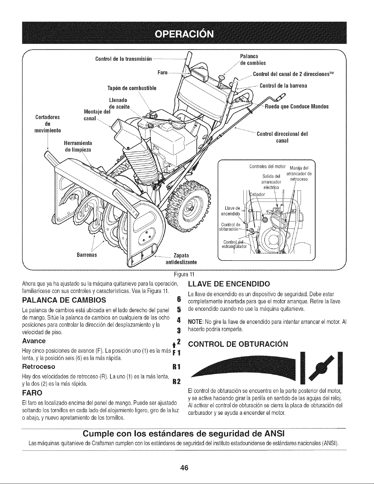
f Palanca
Controldela transrnisi6n /de carnhios
Cortadores
de
movimiento
Tap6ndecombustible
\
\
Llenado \
\
de aceite \
IVlontajedel
canal_
Herrarnienia
de lirnpieza
Barrenas
Zapata
antidesiizante
,_ /Control delcanalde 2 direccionesTM
..............Controldela barrena
'_:L__e ConduceIVlandos
7/_
//'_ Controldirectional del
canal
Controlesdel motor Manijadel
arrancador de
Salidadel
retrooeso
arrancador /
el_ctrico /
eooendid\,___
Controlde " \ J _'..11"_A ! / I
obturaci6n-- O_'__y
ControJx_d----./_/l L_JI) I_ //f_.
estranlulad°r ]k_ t_" ]
.................. J
Figura11
Ahoraqueya ha ajustadosu la m_tquinaquitanieveparala operaci6n,
familiaricesecon suscontrolesy caracteristicas.Veala Figura11.
PALANCA DE CAMBIOS 6
Lapalancade cambiosest,. ubicadaen el lado derechodel panel 5
de mango.Sit0ela palancade cambiosencualquierade lasocho 4
posicionesparacontrolarla direcci6ndel desplazamientoy la
velocidadde piso. 3
Avarice t 2
J
LLAVE DE ENCENDIDO
LaIlavede encendidoes un dispositivode seguridad.Debeestar
completamenteinsertadaparaque el motor arranque.Retirela Ilave
de encendidocuandono usela m_tquinaquitanieve.
NOTE:No girela Ilavedeencendidoparaintentararrancarel motor.AI
hacerlopodria romperla.
CONTROL DE OBTURACION
Haycincoposicionesde avance(F). La posici6nuno (1) es la m_tsF 1
osici,nseis,,,esOo, o o.o'' I''1
Haydos velocidadesde retroceso(R). La uno (1) es la m_tslenta,
y la dos (2)es lam_.sr_.pida. R2
FARO Elcontroldeobturaci6nse encuentraen la parteposteriordel motor,
y se activahaciendogirar la perillaen sentidode lasagujasdel reloj.
Elfaro es Iocalizadoencimadel panel de mango.Puedeser ajustado AI activarel controlde obturaci6nse cierralaplaca deobturaci6ndel
soltandolostornillosen cadaladodelalojamientoligero,giro de la luz carburadory se ayudaaencenderel motor.
o abajo,y nuevoapretamientode los tornillos.
Cumple con los est_ndares de seguridad de ANSI
Lasm_.quinasquitanievedeCraftsmancumplenconlosestandaresdeseguridaddel institutoestadounidensedeest_mdaresnacionales(ANSI).
46
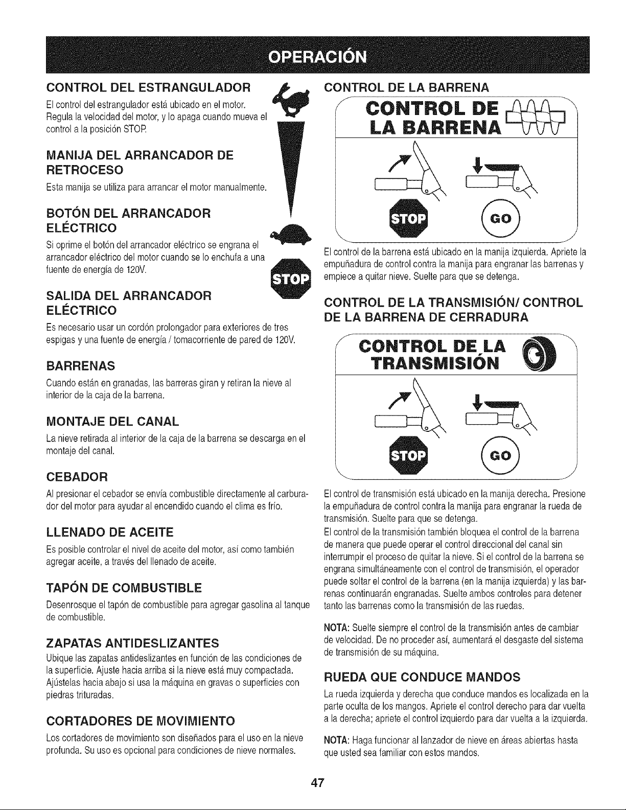
CONTROL DEL ESTRANGULADOR
Elcontroldel estranguladoresterubicadoen el motor.
Regulalavelocidaddel motor,y Io apagacuandomuevael
controla la posici6nSTOR
MANIJA DEL ARRANCADOR DE
RETROCESO
Estamanijase utiliza para arrancarel motormanualmente.
BOTON DEL ARRANCADOR
EL#CTRICO
Si oprimeel bot6ndelarrancadorelectricose engranael
arrancadorelectricodel motorcuandose Ioenchufaa una
fuentedeenergia de 120V.
SALIDA DEL ARRANCADOR
ELC:CTRICO
Es necesariousar uncord6nprolongadorparaexterioresde tres
espigasy unafuentede energia/ tomacorrientede paredde 120V.
BARRENAS
Cuandoestgtnen granadas,las barrerasgirany retiranla nieveal
interiorde la cajade labarrena.
MONTAJE DEL CANAL
La nieveretiradaal interiordela cajade labarrenase descargaenel
montajedel canal.
CEBADOR
AI presionarel cebadorse enviacombustibledirectamenteal carbura-
dordel motorparaayudaralencendidocuandoel clima es fifo.
LLENADO DE ACEITE
Es posiblecontrolarel niveldeaceitedelmotor,asi comotambien
agregaraceite,a travesdel Ilenadodeaceite.
TAPON DE COMBUSTIBLE
Desenrosqueel tap6nde combustiblepara agregargasolinaal tanque
decombustible.
ZAPATAS ANTIDESLIZANTES
Ubiquelaszapatasantideslizantesen funci6nde lascondicionesde
lasuperficie.Ajustehaciaarribasi la nieveest,.muycompactada.
AjOstelashaciaabajosi usala m_tquinaen gravaso superficiescon
piedrastrituradas.
CORTADORES DE MOVIMIENTO
Loscortadoresde movimientosondiseRadosparael usoen la nieve
profunda.Su usoes opcionalparacondicionesde nievenormales.
CONTROL DE LA BARRENA
J CONTROL DE
LA BARRI NA
@
Elcontrolde labarrenaestAubicadoen la manijaizquierda.Aprietela
empuhadurade control contrala manijapara engranarlas barrenasy
empiecea quitarnieve.Suelteparaquese detenga.
CONTROL DE LA TRANSMISION/CONTROL
DE LA BARRENA DE CERRADURA
CONTROL DE LA \
TRANSM|S|6N
J
Elcontroldetransmisi6nest,. ubicadoen la manijaderecha.Presione
laempuhadurade controlcontra la manijapara engranarla ruedade
transmisi6n.Sueltepara que se detenga.
Elcontrolde latransmisi6ntambienbloqueael controlde labarrena
de maneraquepuedeoperarel controldireccionaldel canalsin
interrumpirel procesode quitarla nieve.Siel controlde la barrenase
engranasimult_.neamentecon elcontrolde transmisi6n,el operador
puedesoltarel controlde labarrena(enla manijaizquierda)y lasbar-
renascontinuar_.nengranadas.Suelteamboscontrolesparadetener
tantolas barrenascomola transmisi6ndelas ruedas.
NOTA:Sueltesiempreel controlde latransmisi6nantesdecambiar
de velocidad.De noprocederasi,aumentar_tel desgastedel sistema
de transmisi6nde su m_tquina.
RUEDA QUE CONDUCE MANDOS
Larueda izquierday derechaque conducemandoses Iocalizadaen la
parteocultade los mangos.Aprieteel control derechopara dar vuelta
a laderecha;aprieteel controlizquierdoparadar vueltaa la izquierda.
NOTA:Hagafuncionaral lanzadorde nieveen Areasabiertas hasta
que ustedseafamiliarcon estosmandos.
47
CONTROL DEL CANAL DE
2 DIRECCIONES TM
La nievede distanciaes lanzadapuedeser cambiadoajustandoel
_mgulode la asambleade tolva.Avanceel controlde inclinaci6nde
tolvaparadisminuirla distancia,haciael reversoparaaumentar.
CONTROL DIRECClONAL DEL CANAL
Lacontroldireccionaldel canales Iocalizadaen el lado izquierdodel
lanzadorde nieve.
,, Paracambiarla direcci6nhacialacual se arrojala nieve,gire
ensentidode lasagujasdel relojparadescargarlanievehacia
la izquierda,yen direcci6ncontrariade las agujasdel relojpara
descargarlahacialaderecha.
HERRAMIENTA DE LIMPIEZA
Nuncausesusmanospara liberar un montajede canaltapado.Ante_
de destaparlo,apagueel motory permanezcadetr_tsde las manijas
hastaquetodas las partesm6vilesse hayandetenido.
La herramientadelimpiezadelcanalest,.ajustadaconvenientemente
a laparte posteriorde lacaja dela barrenaconun pasadordeensam-
blado.Sise acumulannievey hieloen elcanalde descargadurante
laoperaci6n,procedacomose indicaa continuaci6npara limpiarde
manerasegurael montajedelcanaly laaberturadelcanal:
1. Suelteel controlde la barrenay el controlde la transmisi6n.
2. Paradetenerel motorsaquela Ilavede encendido.
3. Saquela herramientade limpiezadel pasadorque la ajusta a la
parteposteriordela cajade labarrena.
4. Use el extremoconformade pala de la herramientadelimpieza
paradesplazary recogerla nievey el hieloquese formaron
cercadel conjuntodel canal.
5. Vuelvaa ajustarla herramientade limpiezaal pasadordeens-
ambladoubicadoen la parte posteriorde lacaja de labarrena,
insertede nuevola Ilavedeencendidoy enciendael motorde la
m_tquinaquitanieve.
6. Paradoen la posici6ndel operador(detr_.sdelam_tquinaquita-
nieve),engraneelcontroldelabarrenaduranteunossegundospara
eliminarla nieveoel hieloquehayanquedadoenelconjuntodel
canal.
ANTES DE ENCENDER EL MOTOR
1. Saquela varilladel nivelde aceitedel orificio de Ilenadode
aceite.
2. Controley compruebeque el nivelde aceite este hastaarribaen
lamarcaFULLdela varilladel niveldel aceite.
3. Siel niveldeaceitenoIlegahastaFULL,viertaaceitede motor
nuevo(5W-30,con unaclasificaci6nminimade SL/SJ)lenta-
mentea travesdela abertura.Vuelvaa colocarlavarilladel nivel
aceiteen el Ilenadodeaceitey controlenuevamenteel nivelde
aceite.
Gasolina
Tengaextremocuidadocuandomanipulegasolina.La gasolinaes
altamenteinflamabley sus vaporespuedencausarexplosiones.
Nuncaagreguecombustiblea lam_tquinaen interioreso mientras
el motorest,.calienteo enfuncionamiento.Apagueloscigarrillos,
cigarros,pipasy otrasfuentesdecombusti6n.
,, Almacenelagasolinaen un recipienteaprobadolimpioy coloque
latapaen el recipiente.
,, AsegOresede queel recipientedesdeel cualviertela gasolina
estelimpioy noesteoxidadonicontaminadoconotraspartfculas
extrahas.
NOTA:Dentrode laaperturaparaIlenadode combustiblepuede
encontrarseunatapa guardapolvosde pl_tstico.Retirey descarte,si la
hubiera.
,, Llenesiempreel tanquede combustibleal aire librey use un
embudoo picopara evitarderramamientos.
,, Lleneel tanquedecombustiblecongasolinasinplomo,limpiay fresca.
,, NuncaIlenecompletamenteeltanque.Lleneeltanquehasta1/2pulgpor
debajodeltope,dejandoasiespacioparaladilataci6ndelcombustible.
,, AsegOresede limpiarel combustiblequese hayaderramado
antesde arrancarel motor.
ENCENDIDO DEL MOTOR
1. Conecteel cablede la bujiaa lamisma.Compruebequeel lazo
de metaldelextremode labujiaest_bienajustado(dentrode la
mangade goma)sobrela puntametalicade labujia.
2. AsegOresede que el controlde la barrenay el control de la
transmisi6nestenen posici6ndesengranada(sin presionar).
3. Muevael controldelestranguladora la posici6nFAST41_.
Insertela Ilavedeencendidoen la ranura.AsegOresede que
entrea presi6nensu lugar.No intentegirarla Ilave.
Lea,comprenday sigatodaslas instruccionesy advertenciasque
aparecenen lam_tquinayen estemanualantesde operarla.
Aceite
El motorse envi6con aceiteen el motor.Controleel nivelde aceite
antesde cadaoperaci6nparaasegurarsede quehayaaceite
suficienteenel motor.Paraobtenerm_tsinstrucciones,remftasea los
pasosqueaparecenen la p_tgina51.
NOTA:Elmotorno puedearrancarsi laIlavenoestercompletamente
insertadaenel interruptordeencendido.
Arrancador el_ctrico
Determinesi el cableadode su hogares un sistemade tres cables
conectadoa tierra.Consultecon unelectricistamatriculadosi no ester
seguro.
48
Elarrancadorelectricoopcionalesterequipadocon un cable de ali-
mentaci6ny un enchufede tres terminalesconectadosa tierray ester
disehadopara operarcon corrientedom_sticade 120voltios.Debe
serutilizadocon unrecept_.culode tresterminalescorrectamente
conectadoa tierraen todomomentoparaevitar la posibilidadde
descargaselectricas.Siga todas las instruccionescuidadosamente
paraoperarel arrancadorelectrico.
Si cuentaconun recept_tculodetresterminales,siga lossiguientes
pasos:
1. Conecteel prolongadora la salidasituadaen la superficiedel
motor.Conecteel otroextremodel prolongadoren unrecept_.culo
deCA conconexi6na tierradetresterminalesde 120voltios,en
un_.reabien ventilada.
2. Gire el controlde obturaci6na posici6nde obturaci6nFULL
IJl (paraencendidocon el motorenfifo).
NOTA:si el motorya estacaliente,ubiqueelcontroldel obturadoren
posici6nOFFen lugardeFULLIJl •
3. Presioneel cebadordos otres vecesparaarrancarel motoren
fifo, asegur_mdosede cubrirel orificiode ventilaci6nsituadoen
el centrodel cebadorcuandoestepresionando.
NOTA:NO UTILICEel cebadorpara reiniciarun motorcalientetras
unadetenci6nbreve.
4. Presioneel bot6ndelarrancadorparaarrancarel motor.
NOTA:NOmantengael bot6noprimidodurantem_.sde siete (7)
segundosa la vez.Si Iohace,puededaharel arrancadorelectricodel
motor.
5. Unavezencendidoel motor,suelteelbot6ndel arrancador.
6. Mientrasse calientaelmotor,gire lentamenteelcontroldel obtu
radora posici6nOFF(apagado).Si el motorfalla,vuelva a girar
r_tpidamenteel obturadora posici6nFULL IJl Y luego,
lentamente,a posici6nOFFde nuevo.
7. Cuandodesconecteel prolongador,desenchufesiempreel
extremodelreceptaculode tres terminalesen el tomacorriente
de paredantesdedesenchufarel extremoopuestode la
m_tquinaquitanieve.
Arrancador de retroceso
1. Gire el controlde obturaci6na posicbn de obturaci6nFULL
IJl (encendidocon el motoren fifo).
NOTA:Isi el motorya estacaliente,ubiqueelcontroldel obturadoren
posici6nOFFen lugardeFULLI,,ol.
2. Presioneel cebadordos otres vecesparaarrancarel motoren
fifo, asegur_mdosede cubrirel orificiode ventilaci6nsituadoen
el centrodel cebadorcuandoestepresionando.
NOTA:NO UTILICEel cebadorparareiniciarun motorcalientetras
unadetenci6nbreve.
NOTA:talvezsea necesariouncebadoadicionalsi la temperaturaes
inferiora 15° Fahrenheit.
3. Tome la manijadel arrancadorderetrocesoy tire de la cuerda
haciaafueralentamente.Enel momentoen el quese haga
levementem_.sdificiltirarde la cuerda,permitaque la misma
retrocedalentamente.
4. Tire de la manijadel arrancadorcon un movimientofirme y
r_tpido.Nosueltelamanijani permitaquese desenganche.
Mantengala manijadel arrancadorfirmementesujeta y permita
quela cuerdaretrocedalentamente.
5. Mientrasse calientael motor,gire lentamenteel control del
obturadora posici6nOFF (apagado).Si el motorfalla, vuelvaa
girarr_tpidamenteel obturadora posici6nFULL Ill Yluego,
lentamente,a posici6nOFFde nuevo.
NOTA:permitaque el motorse calienteduranteunosminutostrasel
arranque.El motornodesarrollar_ttodasu potenciahastaque alcance
temperaturasoperativas.
DETENCION DEL MOTOR
Dejeencendidoel motordurantealgunosminutosantesde detenerlo
parapermitirquese sequela humedaden el mismo.
1. Muevael controldel estranguladora la posiciSnSTOP_.
2. Retirela Ilavede encendidoy gu_.rdelaen unlugar seguro.
3. Limpiela nievey la humedaddel &reaalrededordel motor,asi
comotambienenel &rea(y alrededordeesta)del interiorde los
controlesde latransmisi6ny dela barrena.Asimismo,enganche
y suelteamboscontrolesvariasveces.
PROCEDIMIENTO PARA ENGRANAR LA
TRANSMISION
1. Con el control del estranguladoren posici6nr_.pida'_ (dibujo
de unconejo),muevala palancadecambiosa unadelas seis
posicionesde avance(F) o de lasdos posicionesdereversa(R).
Seleccionelavelocidadadecuadapara el estadode la nieveexis-
tentey unavelocidadconla que se sientac6modo.
NOTA:AIseleccionaruna velocidadde la transmisi6n,use las veloci-
dadesm_tslentas hastaque se sientac6modoy se hayafamiliarizado
con el funcionamientode lam_tquinaquitanieve.
2. Aprieteel controlde la transmisi6ncontrala manijaderecha,y la
m_.quinaquitanievese mover&Suelteloy se detendr_tel
movimientode latransmisi6n.
NOTA:NUNCAcambielaposici6nde lapalancade cambios(cambio
de velocidadeso de direcci6nde desplazamiento)sin soltar primeroel
controlde transmisi6ny detenerpor completolam_.quinaquitanieve.
Estoproducir_tundesgasteprematurodel sistemade transmisi6nde
lam_tquinaquitanieve.
PROCEDIMIENTO PARA ENGRANAR LAS
BARRENAS
1. Aprieteel control de la barrenacontra la manijay las barrenas
rotaran.Sueltelay lasbarrenasse detendran.
49
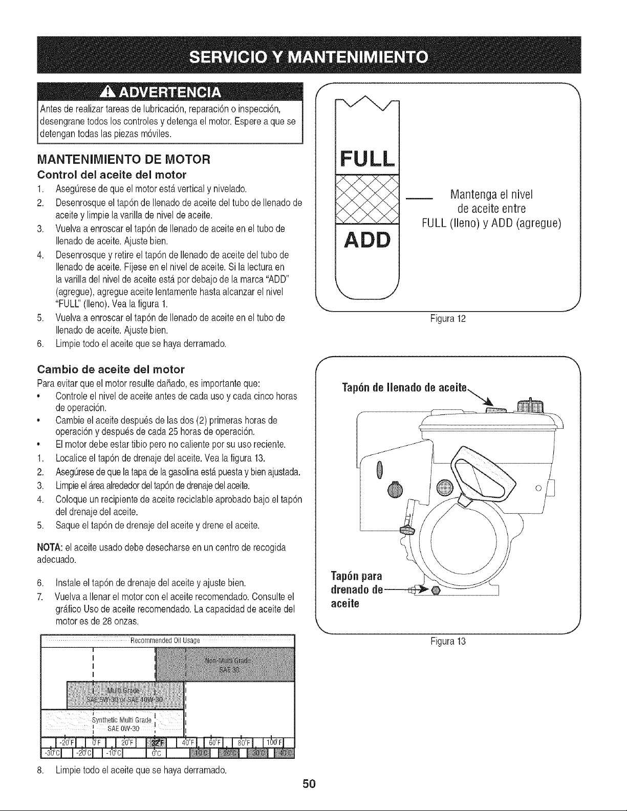
Antesde realizartareasde lubricaci6n,reparaci6no inspecci6n,
desengranetodoslos controlesy detengael motor.Esperea que se
_detengantodas as p ezas m6v es.
MANTENIMIENTO DE MOTOR
Control del aceite del motor
1. AsegOresede que el motorestAverticaly nivelado.
2. Desenrosqueel tap6nde Ilenadode aceitedel tubo de Ilenadode
aceitey limpielavarillade niveldeaceite.
3. Vuelvaa enroscarel tap6nde Ilenadode aceiteen el tubo de
Ilenadode aceite.Ajustebien.
4. Desenrosquey retireeltap6n de Ilenadode aceite del tubo de
Ilenadode aceite.Fijese en el niveldeaceite.Sila lecturaen
la varilladel niveldeaceiteestapordebajode la marca"ADD"
(agregue),agregueaceite lentamentehastaalcanzarel nivel
"FULl" (lleno).Yea la figura 1.
5. Vuelvaa enroscarel tap6nde Ilenadode aceiteen el tubo de
Ilenadode aceite.Ajustebien.
6. Limpietodo el aceite que se hayaderramado.
Cambio de aceite del motor
Paraevitarque el motorresultedahado,es importanteque:
,, Controleel nivelde aceiteantesde cadauso y cadacincohoras
deoperaci6n.
,, Cambieel aceitedespuesde lasdos (2) primerashorasde
operaci6ny despuesde cada25 horasde operaci6n.
,, Elmotordebe estartibio peronocalienteporsu usoreciente.
1. Localiceel tap6nde drenajedel aceite.Vea la figura13.
2. AsegOresede que la tapade la gasolinaestApuestay bienajustada.
3. LimpieelAreaalrededordeltap6nde drenajedelaoeite.
4. Coloqueun recipientede aceite reciclableaprobadobajo el tap6n
deldrenajedelaceite.
5. Saqueel tap6n de drenajedel aceitey dreneel aceite.
NOTA:el aceiteusadodebedesecharseen un centrode recogida
adecuado.
6,
7.
Instaleeltap6n de drenajedel aceite y ajustebien.
Vuelvaa Ilenarel motorcon el aceiterecomendado.Consulteel
graficoUsode aceiterecomendado.La capacidadde aceite del
motores de 28onzas.
Recommended Oil Usage
I
I
I
I
f --,,
FULL
ADD
Mantenga el nivel
de aceite entre
FULL (lleno) y ADD (agregue)
Figura12
J
f
0
Tap6n para
drenad0
aceite
Figura 13
8. Limpietodoel aceiteque se hayaderramado.
5O
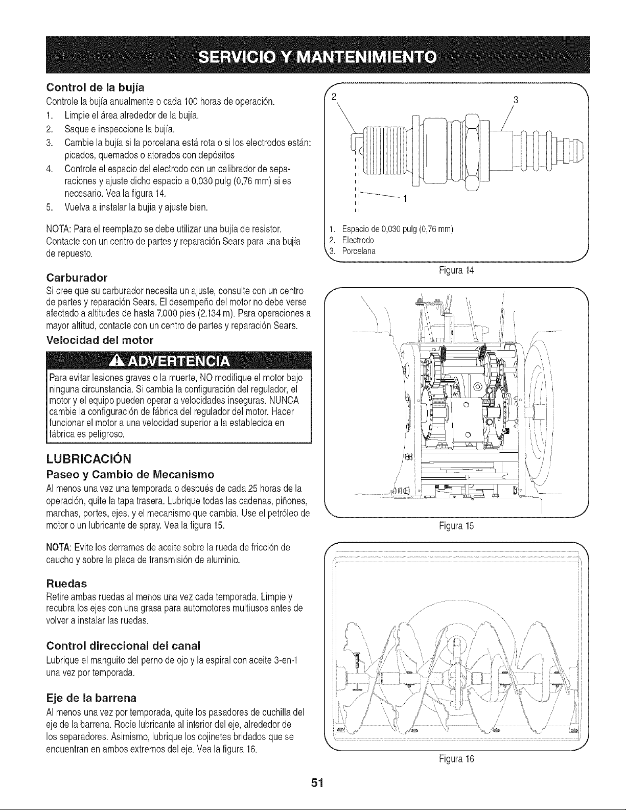
Control de la bujia
Controlelabujiaanualmenteo cada 100horasde operaci6n.
1. Limpieel _.reaalrededorde labujia.
2. Saquee inspeccionela bujia.
3. Cambiela bujia si la porcelanaesta rotao si loselectrodosest_m:
picados,quemadoso atoradoscon dep6sitos
4. Controleel espaciodel electrodocon un calibradorde sepa-
racionesy ajustedichoespacioa 0,030pulg(0,76mm) si es
necesario.Vea la figura14.
5. Vuelvaa instalarla bujiay ajustebien.
NOTA:Parael reemplazose debeutilizarunabujiade resistor.
Contactecon uncentro de partesy reparaci6nSearspara una bujia
de repuesto.
Carburador
Si creequesu carburadornecesitaun ajuste,consultecon un centro
departes y reparaci6nSears.Eldesempehodelmotorno debeverse
afectadoa altitudesde hasta7.000pies (2.134m). Para operacionesa
mayoraltitud,contactecon uncentrode partesy reparaci6nSears.
Velocidad del motor
Paraevitarlesionesgraveso la muerte,NO modifiqueel motorbajo
ningunacircunstancia.Sicambia la configuraci6ndel regulador,el
motory elequipo puedenoperara velocidadesinseguras.NUNCA
cambiela configuraci6nde f_.bricadel reguladordel motor.Hacer
funcionarel motora unavelocidadsuperiorala establecidaen
f_tbricaes peligroso.
LUBRICACI(SN
Paseo y Cambio de Mecanismo
AI menosunavez unatemporadao despuesdecada25 horasdela
operaci6n,quitela tapatrasera.Lubriquetodaslascadenas,pihones,
marchas,portes,ejes,y el mecanismoque cambia.Use el petr61eode
motoro un lubricantede spray.Yealafigura 15.
NOTA:Evitelos derramesdeaceitesobrela ruedadefricci6nde
cauchoy sobrela placade transmisi6nde aluminio.
Ruedas
Retireambasruedasal menosunavezcada temporada.Limpiey
recubralosejescon unagrasaparaautomotoresmultiusosantes de
volvera instalarlas ruedas.
Control direccional del canal
Lubriqueel manguitodel pernode ojoy la espiralconaceite3-en-1
unavez por temporada.
Eje de la barrena
AI menosunavezpor temporada,quitelos pasadoresde cuchilladel
ejede labarrena.Rode lubricanteal interiordel eje,alrededorde
los separadores.Asimismo,lubriquelos cojinetesbridadosquese
encuentranen ambosextremosdel eje.Vealafigura 16.
f
2 3
II
II
II
1. Espaciode0,030pulg(0,76ram)
2. Electrodo
3. Porcelana
Figura 14
J
\
ill
i
Figura15
Figura16
51
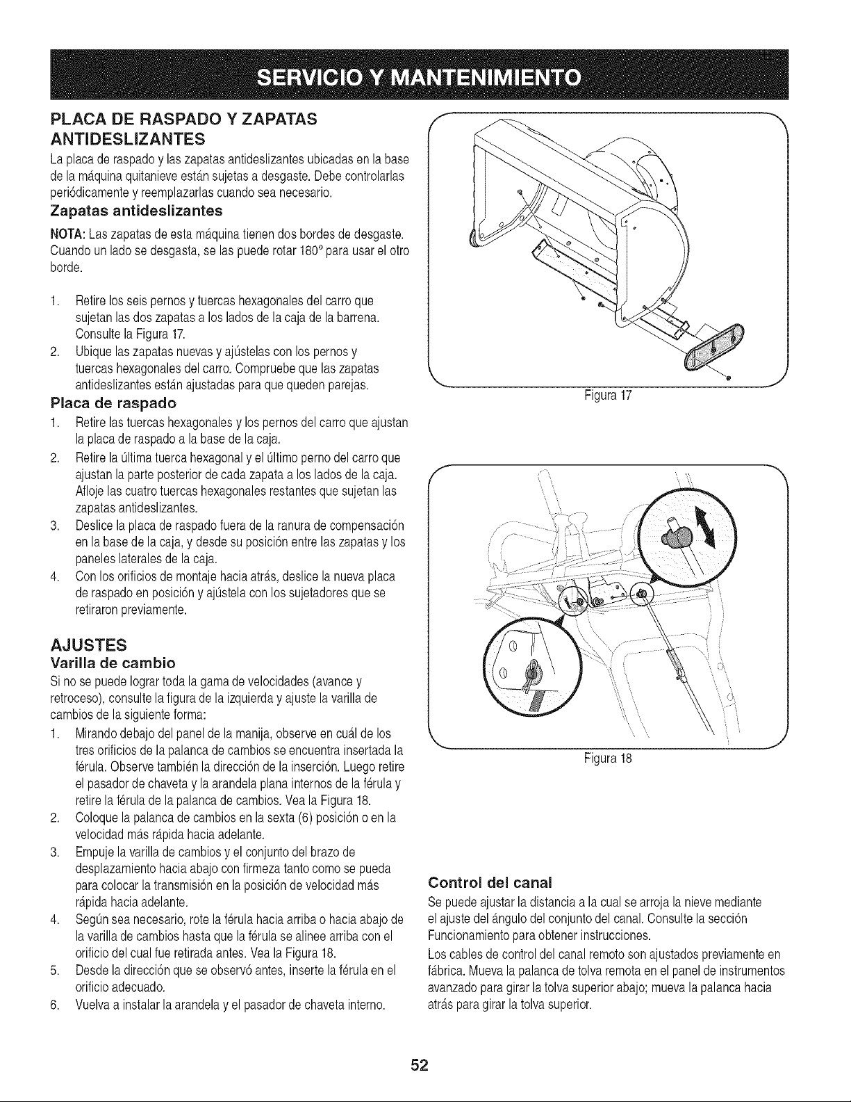
PLACA DE RASPADO Y ZAPATAS
ANTIDESLIZANTES
Laplacade raspadoy laszapatasantideslizantesubicadasen la base
de lam_.quinaquitanieveestansujetasa desgaste.Debecontrolarlas
peri6dicamentey reemplazarlascuandosea necesario.
Zapatas antideslizantes
NOTA:Laszapatasdeesta m_.quinatienendos bordesdedesgaste.
Cuandoun ladose desgasta,se las puederotar1800parausarel otro
borde.
1. Retirelos seis pernosy tuercashexagonalesdel carroque
sujetanlasdos zapatasa los ladosde lacaja de labarrena.
Consultela Figura17.
2. Ubiquelaszapatasnuevasy ajOstelascon los pernosy
tuercashexagonalesdel carro.Compruebeque laszapatas
antideslizantesest_tnajustadaspara que quedenparejas.
Placa de raspado
1. Retirelas tuercashexagonalesy los pernosdel carro que ajustan
la placade raspadoa la basede la caja.
2. Retirela Oltimatuerca hexagonaly el Oltimoperno del carroque
ajustanlaparte posteriorde cada zapataa los ladosde lacaja.
Aflojelas cuatrotuercashexagonalesrestantesque sujetan las
zapatasantideslizantes.
3. Deslicela placade raspadofuerade la ranurade compensaci6n
enla basede lacaja,y desdesu posici6nentrelas zapatasy los
paneleslateralesde la caja.
4. Con losorificiosde montajehaciaatr_ts,deslicela nuevaplaca
deraspadoen posici6ny ajOstelacon lossujetadoresque se
retiraronpreviamente.
AJUSTES
Varilla de cambio
Si nose puedeIogrartoda la gamadevelocidades(avancey
retroceso),consultela figuradela izquierday ajustelavarillade
cambiosde lasiguienteforma:
1. Mirandodebajodel panelde la manija,observeen cu_.lde los
tresorificiosde lapalancadecambiosse encuentrainsertadala
ferula.Observetambienladirecci6nde la inserci6n.Luegoretire
el pasadordechavetay la arandelaplanainternosde la f_rulay
retirela f_rulade la palancadecambios.YealaFigura18.
2. Coloquela palancade cambiosen la sexta(6) posici6no en la
velocidadm_.sr_.pidahaciaadelante.
3. Empujela varillade cambiosy el conjuntodelbrazode
desplazamientohaciaabajoconfirmezatantocomo se pueda
paracolocarla transmisi6nen laposici6nde velocidadm_ts
r_.pidahaciaadelante.
4. SegOnsea necesario,rote laf_rulahaciaarribao haciaabajode
la varillade cambioshastaquelaferulase alineearribacon el
orificiodelcual fue retiradaantes.Veala Figura18.
5. Desdela direcci6nque se observ6antes,insertela ferulaen el
orificioadecuado.
6. Vuelvaa instalarla arandelay el pasadorde chavetainterno.
f --,,
Figura17
\ \
Figura18
Control del canal
Sepuedeajustarla distanciaa lacual se arrojalanievemediante
el ajustedel_.ngulodel conjuntodel canal.Consultela secci6n
Funcionamientoparaobtenerinstrucciones.
Loscablesde controldelcanalremotoson ajustadospreviamenteen
f_tbrica.Muevalapalancadetolva remoraen el panelde instrumentos
avanzadoparagirar la tolva superiorabajo;muevala palancahacia
atr_tspara girar la tolva superior.
52
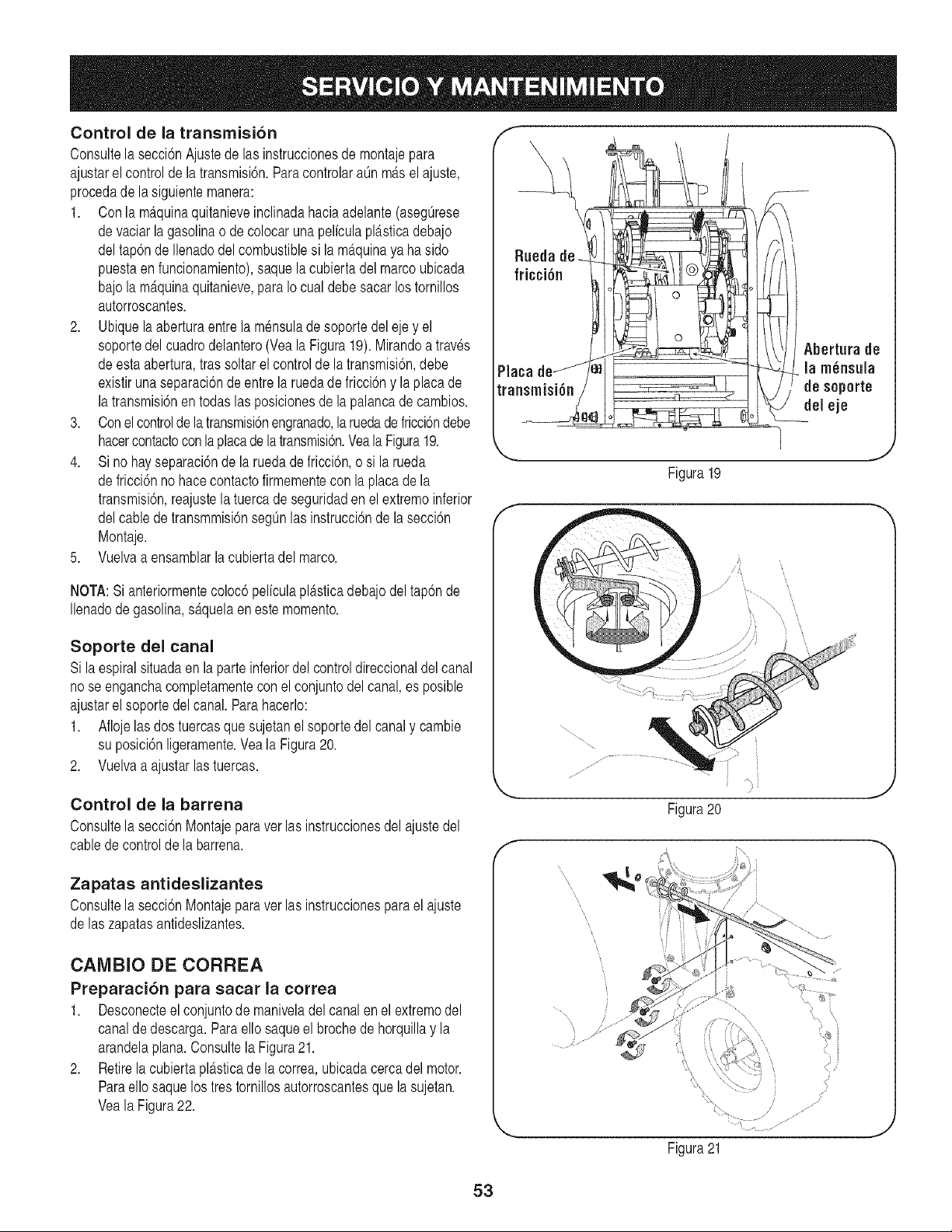
Control de la transrnisl6n
Consultela secci6nAjustede las instruccionesde montajepara
ajustarelcontrol de latransmisi6n.Paracontrolara0n m_tselajuste,
procedade lasiguientemanera:
1. Conla m_.quinaquitanieveinclinadahaciaadelante(aseg0rese
devaciar la gasolinao de colocarunapeliculapl_tsticadebajo
deltap6nde Ilenadodelcombustiblesi la m_.quinaya haside
puestaenfuncionamiento),saquela cubiertadelmarcoubicada
bajola m_.quinaquitanieve,para Io cualdebe sacar lostornillos
autorroscantes.
2. Ubiquela aberturaentre la mensulade soportedel eje y el
soportedelcuadrodelantero(Veala Figura19).Mirandoa traves
deesta abertura,tras soltar el controlde la transmisi6n,debe
existirunaseparaci6ndeentrela ruedade fricci6ny laplaca de
la transmisi6nen todaslas posicionesdela palancade cambios.
3. Conel controlde la transmisi6nengranado,laruedade fricci6ndebe
hacercontactoconla placade la transmisi6n.Veala Figura19.
4. Si no hayseparaci6nde la ruedadefricci6n,o si larueda
defricci6nno hacecontactofirmementecon laplacade la
transmisi6n,reajustela tuercade seguridaden el extremeinferior
delcablede transmmisi6nseg0nlas instrucci6nde la secci6n
Montaje.
5. Vuelvaa ensamblarla cubiertadel marco.
NOTA:Sianteriormentecoloc6 pelfculapl4tsticadebajodel tap6nde
Ilenadode gasolina,s@uelaeneste memento.
Soporte del canal
Si laespiralsituadaen laparteinferiordelcontroldireccionaldelcanal
nose enganchacompletamenteconel conjuntodel canal,es posible
ajustarelsoporte del canal. Parahacerlo:
1. Aflojelas dostuercasque sujetanel soportedel canaly cambie
su posici6nligeramente.Vea la Figura20.
2. Vuelvaa ajustarlastuercas.
Control de la barrena
Consultela secci6nMontajeparaver las instruccionesdel ajustedel
cabledecontrolde la barrena.
Zapatas antidesllzantes
Consultela secci6nMontajeparaver las instruccionesparael ajuste
de laszapatasantideslizantes.
CAIVlBIO DE CORREA
Preparaci6n para sacar la correa
1. Desconecteel conjuntode maniveladel canalen el extremedel
canaldedescarga.Para ello saqueel brochede horquillay la
arandelaplan& Consultela Figura21.
2. Retirela cubiertaplasticade la correa,ubicadacercadel motor.
Paraellosaquelos tres tornillosautorroscantesquela sujetan.
Veala Figura22.
f --,,
Abertura de
Placa la m_nsula
transmisi6n de seperte
del eje
f
Figura19
J
/
f
,,,,"
,,,,"
J
\
Figura21
J
53
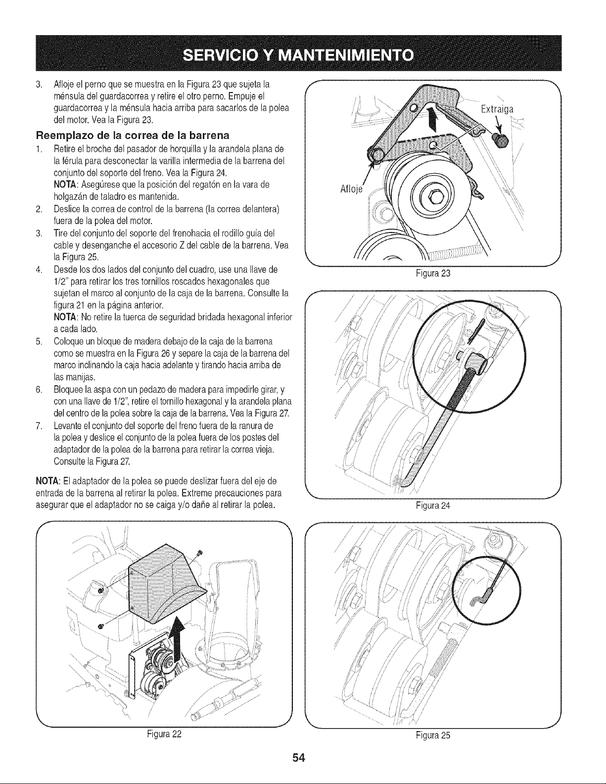
3. Aflojeel perno que se muestraen la Figura23 que sujeta la
m_nsuladel guardacorreay retireel otro perno.Empujeel
guardacorreay la m_nsulahaciaarribapara sacarlosde la polea
delmotor.Vea la Figura23.
Reernplazo de la correa de la barrena
1. Retireel brochedel pasadorde horquillay la arandelaplanade
la ferulaparadesconectarlavarilla intermediade labarrenadel
conjuntodel soportedelfreno.Veala Figura24.
NOTA:AsegOresequela posici6ndelregat6nen la varade
holgaz_.ndetaladroes mantenida.
2. Deslicela correade controlde la barrena(la correadelantera)
fuerade lapoleadelmotor.
3. Tiredel conjuntodel soportedel frenohaciael rodilloguiadel
cabley desengancheelaccesorioZ del cablede labarrena.Yea
la Figura25.
4. Desdelos dos ladosdel conjuntodel cuadro,useuna Ilavede
1/2"pararetirarlostrestornillosroscadoshexagonalesque
sujetanel marcoalconjuntode lacajade la barrena.Consultela
figura21en lap_.ginaanterior.
NOTA:No retirelatuercade seguridadbridadahexagonalinferior
a cadalado.
5. Coloqueun bloquedemaderadebajode lacajadelabarrena
comose muestraen la Figura26y separela cajade la barrenadel
marcoinclinandola caja haciaadelantey tirandohaciaarribade
las manijas.
6. Bloqueela aspaconun pedazodemaderaparaimpedirlegirar,y
conunaIlavede 1/2",retireeltornillohexagonaly la arandelaplana
delcentrode lapoleasobrelacajadelabarrena.Yea la Figura27.
7. Levanteel conjuntodel soportedel frenofuerade la ranurade
lapoleay desliceelconjuntode la poleafuerade lospostesdel
adaptadorde la poleade la barrenapara retirarla correavieja.
Consultela Figura27.
NOTA:Eladaptadorde la polease puede deslizarfueradel eje de
entradade labarrenaal retirarlapolea.Extremeprecaucionespara
asegurarque el adaptadorno se caiga y/o dahe al retirarla polea.
f
\
ii
/
/
Figura22
f --,,
Extraiga
Aflo
f
f
// i A" i l
II //
// ./
/
Figura23
/
/
/
/
/
/
/
/
/
/
/
Figura24
//
//
i!
//
Figura25
J
54
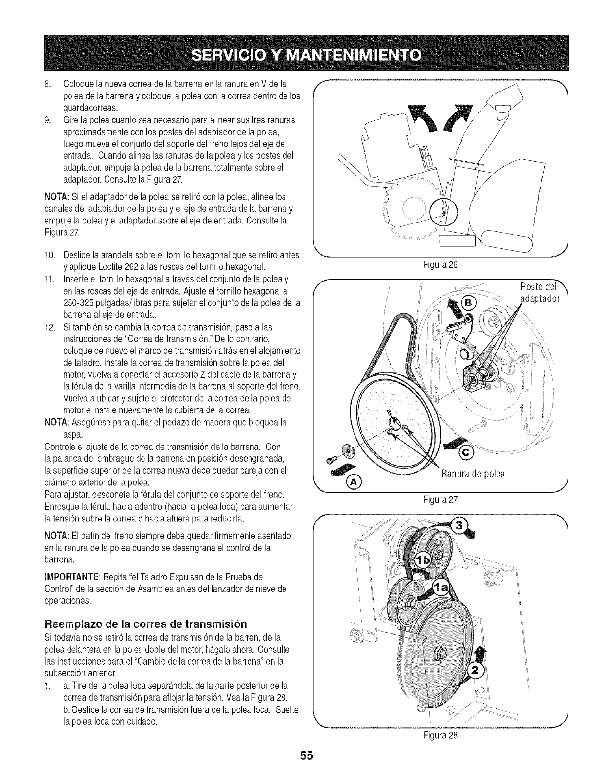
8. Coloquela nuevacorreade labarrenaenla ranuraenV de la
poleade la barrenay coloquela poleacon lacorreadentrode los
guardacorreas.
9. Girelapoleacuantosea necesarioparaalinearsus tresranuras
aproximadamentecon lospostesdel adaptadorde la polea,
luegomuevael conjuntodel soportedelfrenolejosdel ejede
entrada. Cuandoalinealas ranurasde la poleay lospostesdel
adaptador,empujelapolea de la barrenatotalmentesobreel
adaptador.Consultela Figura27.
NOTA:Siel adaptadorde la polea se retir6con la polea,alinee los
canalesdeladaptadorde la poleay el eje de entradade la barrenay
empujela poleay eladaptadorsobreel ejedeentrada.Consultela
Figura27.
10. Deslicela arandelasobreel tornillohexagonalquese retir6antes
y apliqueLoctite262alas roscasdel tornillohexagonal.
11. Inserteel tornillohexagonala travesdelconjuntode la poleay
en lasroscasdelejede entrada.Ajusteel tornillohexagonala
250-325pulgadas/librasparasujetarel conjuntode la poleade la
barrenaaleje de entrada.
12. Si tambiense cambia la correade transmisi6n,pasealas
instruccionesde "Correade transmisi6n."DeIo contrario,
coloquede nuevoel marcode transmisi6natr_.sen el alojamiento
detaladro.Instalela correade transmisi6nsobrela poleadel
motor,vuelvaa conectarel accesorioZ delcablede la barrenay
laf_rulade la varillaintermediade la barrenaal soportedel freno.
Vuelvaa ubicary sujeteel protectorde lacorreadela poleadel
motore instalenuevamentela cubiertade la correa.
NOTA:AsegOreseparaquitarel pedazode maderaquebloqueala
aspa.
Controleel ajustede lacorreade transmisi6nde la barrena. Con
lapalancadelembraguede la barrenaen posici6ndesengranada,
lasuperficiesuperiorde la correanuevadebequedarparejacon el
di_tmetroexteriorde la polea.
Paraajustar,desconetela f_ruladel conjuntode soportedelfreno.
Enrosquela f_rulahaciaadentro(haciala polea Ioca)para aumentar
latensi6nsobre lacorreao haciaafueraparareducirla.
NOTA:Elpatindel frenosiempredebequedarfirmementeasentado
en laranurade lapoleacuandose desengranael controlde la
barrena.
IMPORTANTE:Repita"elTaladroExpulsande laPruebade
Control"dela secci6nde Asambleaantesdel lanzadordenievede
operaciones.
Reemplazo de la correa de transmision
Si todavianose retir6la correade transmisi6ndela barren,de la
poleadelanteraen la polea dobledel motor,h_.galoahora.Consulte
las instruccionesparael "Cambiodela correade la barrena"en la
subsecci6nanterior.
1. a. Tirede la poleaIocasepar_.ndoladela parteposteriorde la
correade transmisi6nparaaflojarla tensi6n.VealaFigura28.
b. Deslicelacorreadetransmisi6nfuerade lapoleaIoca. Suelte
lapoleaIoca concuidado.
f
Figura26
Poste deC"
adaptador
Ranura de polea
Figura27
Figura28
J
55
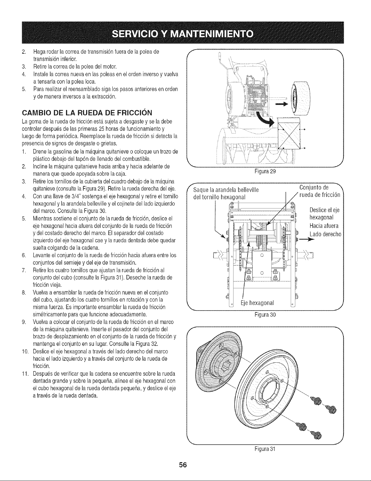
2. Hagarodarlacorreadetransmisi6nfuerade lapoleade
transmisi6ninferior.
3. Retirela correade la poleadel motor.
4. Instalelacorreanuevaen las poleasen elordeninversoy vuelva
atensarlacon la poleaIoca.
5. Pararealizarel reensambladosiga los pasosanterioresen orden
y de manerainversosa laextracci6n.
CAMBIO DE LA RUEDA DE FRICClON
Lagomade la ruedade fricci6nest,.sujetaa desgastey se ladebe
controlardespuesde las primeras25horasde funcionamientoy
luegode formaperi6dica.Reemplacela ruedade fricci6nsi detectala
presenciadesignos de desgasteo grietas.
1. Drenela gasolinade la m_.quinaquitanieveo coloqueun trozode
pNsticodebajodel tap6nde Ilenadodel combustible.
2. Inclinela m_tquinaquitanievehaciaarribay haciaadelantede
maneraque quedeapoyadasobrela caja.
3. Retirelostornillosde la cubiertadel cuadrodebajode la m_tquina
quitanieve(consultela Figura29). Retirela ruedaderechadel eje.
4. Con una Ilavede 3/4" sostengael ejehexagonaly retireel tornillo
hexagonaly la arandelabellevilley el cojinetedel lado izquierdo
delmarco.Consultela Figura30.
5. Mientrassostieneel conjuntode la ruedade fricci6n,deslice el
ejehexagonalhaciaafueradel conjuntode la ruedade fricci6n
y del costadoderechodel marco.Elseparadordelcostado
izquierdodel eje hexagonalcae y laruedadentadadebequedar
sueltacolgandode la cadena.
6. Levanteel conjuntode la ruedade fricci6nhaciaafueraentrelos
conjuntosdel semiejey del eje de transmisi6n.
7. Retirelos cuatrotornillosque ajustanla ruedade fricci6nal
conjuntodel cubo(consultela Figura31). Desechelaruedade
fricci6nvieja.
8. Vuelvaa ensamblarla ruedade fricci6nnuevaen el conjunto
delcubo,ajustandolos cuatrotornillosen rotaci6ny con la
mismafuerza.Es importanteensamblarla rueda de fricci6n
sim6tricamenteparaquefuncioneadecuadamente.
9. Vuelvaa colocarel conjuntode la ruedadefricci6nen el marco
dela m_tquinaquitanieve.Inserteel pasadordel conjuntodel
brazodedesplazamientoen el conjuntode la ruedadefricci6ny
mantengaelconjuntoen su lugar.Consultela Figura32.
10. Desliceel eje hexagonala travesdel lado derechodel marco
haciael ladoizquierdoy a travesdel conjuntode la ruedade
fricci6n.
11. Despuesde verificarque la cadenaseencuentresobrela rueda
dentadagrandey sobre la pequefia,alineeel eje hexagonalcon
el cubohexagonalde la ruedadentadapequefla,y deslice el eje
a travesde laruedadentada.
f --,,
.... J
Figura29
f
f Saque la arandela belleville
del tornillo hexagonal
l,
Ejehexagonal
Conjunto de
de fricci6n
Desliceel eje
hexagonal
Haciaafuera
Ladoderecho
Figura30
,..,-/
Figura31
,J
56
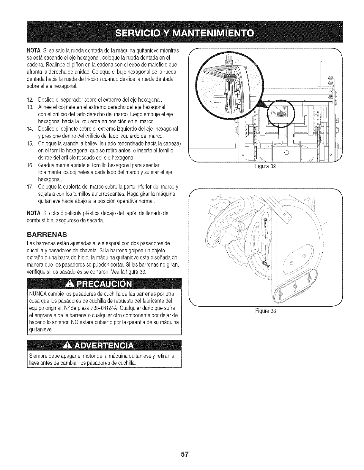
NOTA:Sise sale la ruedadentadade lam_,quinaquitanievemientras
se estersacandoel eje hexagonal,coloquela ruedadentadaenel
cadena.Realineeel pih6n en la cadenacon el cubode maleficioque
afrontaladerechade unidad.Coloqueel buje hexagonaldela rueda
dentadahaciala ruedade fricci6ncuandodeslicelaruedadentada
sobreeleje hexagonal.
12. Desliceel separadorsobre elextremodel ejehexagonal.
13. Alineeel cojineteen el extremoderechodel eje hexagonal
con elorificiodel ladoderechodel marco,luegoempujeeleje
hexagonalhacia la izquierdaen posici6nen el marco.
14. Desliceel cojinetesobreel extremoizquierdodel eje hexagonal
y presionedentrodelorificio del lado izquierdodel marco.
15. Coloquela arandellabelleville(lado redondeadohaciala cabeza)
enel tornillohexagonalque se retir6antes,e inserteel tornillo
dentrodel orificioroscadodeleje hexagonal.
16. Gradualmenteaprieteel tornillo hexagonalparaasentar
totalmenteloscojinetesa cada ladodel marcoy sujetarel eje
hexagonal.
17. Coloquela cubiertadel marcosobre la parte inferiordel marcoy
sujetelaconlos tornillosautorroscantes.Hagagirarla m_tquina
quitanievehaciaabajoa la posici6noperativanormal.
NOTA:Sicoloc6peliculapldtsticadebajodeltap6nde Ilenadodel
combustible,asegOresede sacarla.
BARRENAS
Las barrenasest_.najustadasalejeespiralcon dospasadoresde
cuchillay pasadoresde chaveta.Si labarrenagolpeaun objeto
extrahoo unabarrade hielo,la m_.quinaquitanieveest,.disehadade
maneraque los pasadoresse puedencortar.Si las barrenasnogiran,
verifiquesi los pasadoresse cortaron.Veala figura 33.
NUNCAcambielospasadoresde cuchilladelas barrenasporotra
cosaque los pasadoresde cuchillade repuestodelfabricantedel
equipooriginal,NOde pieza738-04124A.Cualquierdaho que sufra
el engranajedela barrenaocualquierotro componentepor dejarde
hacerloIoanterior,NO estar_tcubiertopor la garanfiade su m_tquina
quitanieve.
©
Figura32
f
Figure33
Siempredebeapagarel motorde la m_tquinaquitanievey retirarla
aveantesde camb ar os pasadoresde cuch a. j
57
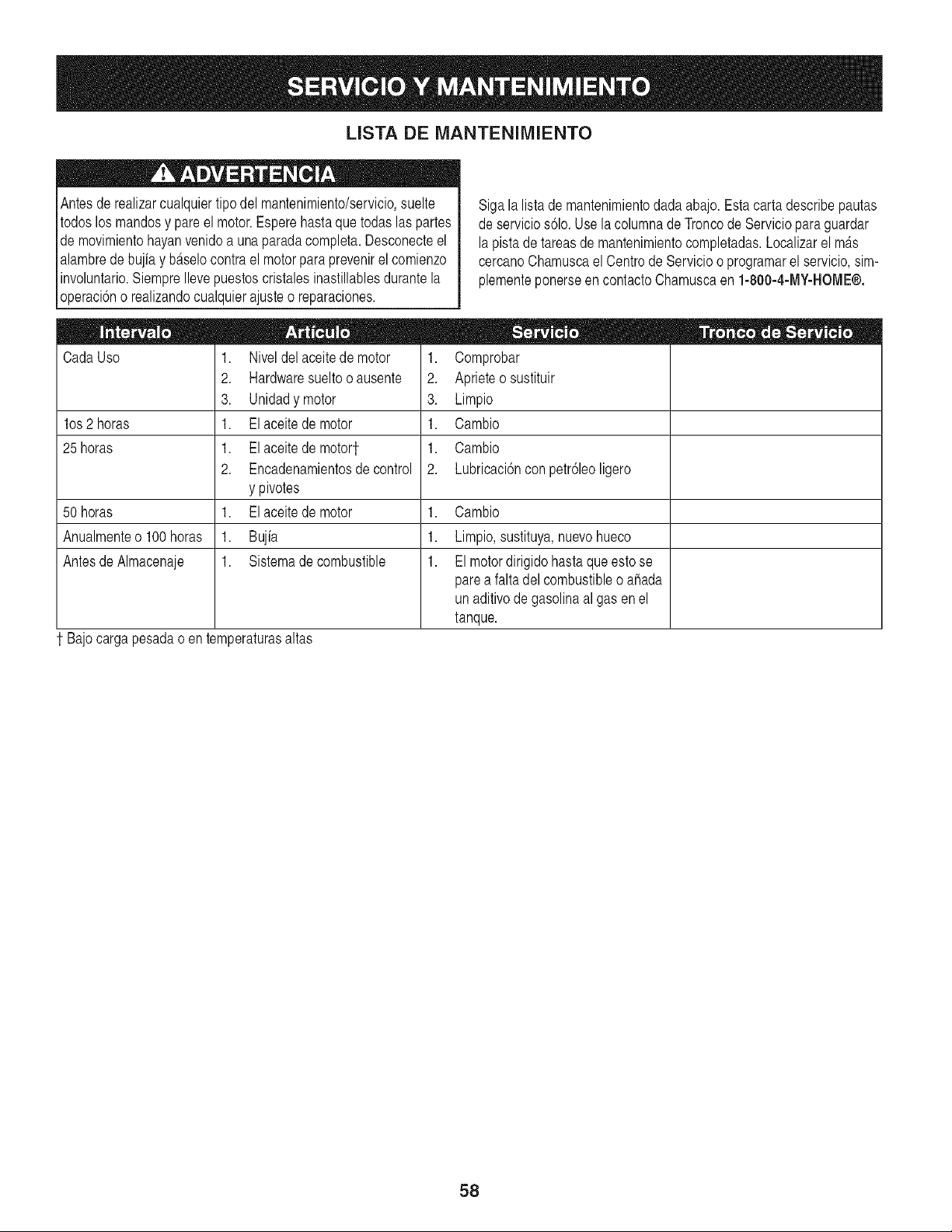
LISTA DE MANTENIMIENTO
Antesde realizarcualquiertipo del mantenimiento/servicio,suelte
todoslos mandosy pare el motor.Esperehastaque todas las partes
de movimientohayanvenidoa unaparadacompleta.Desconecteel
alambrede bujiay b_tselocontrael motorparaprevenirelcomienzo
involuntario.SiempreIlevepuestoscristalesinastillablesdurantela
operaci6no realizandocualquierajusteo reparaciones.
CadaUso
los 2 horas
25 horas
1. Niveldel aceitede motor
2. Hardwaresueltooausente
3. Unidadymotor
1. Elaceite de motor
1. Elaceite de motor1
2. Encadenamientosdecontrol
y pivotes
1. Elaceite de motor
1. Bujia
1. Sistemadecombustible
Sigala listade mantenimientodadaabajo.Estacartadescribepautas
de servicios61o.Usela columnade Troncode Servicioparaguardar
lapistade tareasde mantenimientocompletadas.Localizarel m_.s
cercanoChamuscaelCentro de Servicioo programarel servicio,sim-
plementeponerseen contactoChamuscaen 1-800-4-MY-HOME®.
1. Comprobar
2. Aprieteosustituir
3. Limpio
1. Cambio
1. Cambio
2. Lubricaci6ncon petr61eoligero
50 horas 1. Cambio
Anualmenteo 100horas 1. Limpio,sustituya,nuevohueco
Antesde Almacenaje 1. El motordirigidohasta que estose
parea faltadelcombustibleo ahada
un aditivodegasolinaal gas enel
tanque.
1 Bajocargapesadao entemperaturasaltas
58
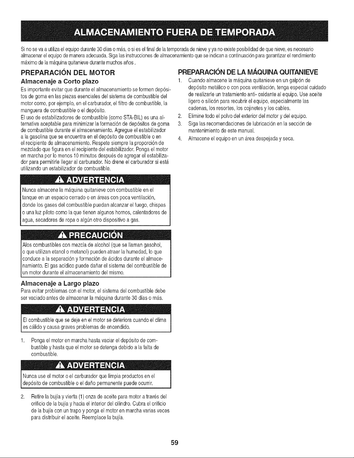
Sinosevaa utilizaelequipodurante30 diaso mAs,o si esel finalde la temporadade nieveyya no existeposibilidadde quenieve,esnecesario
almacenarelequipodemaneraadecuada.Sigalas instruccionesde almacenamientoquese indicanacontinuaci6nparagarantizarel rendimiento
mAximode la mAquinaquitanievedurantemuchosahos.
PREPARACION DEL MOTOR
Almacenaje a Corto plazo
Es importanteevitarque duranteel almacenamientose formendep6si-
tosdegomaen laspiezasesencialesdel sistemade combustibledel
motorcomo,porejemplo,en elcarburador,el filtrode combustible,la
manguerade combustibleo el dep6sito.
Eluso deestabilizadoresdecombustible(comoSTA-BIL)es una al-
ternativaaceptablepara minimizarla formaci6nde dep6sitosdegoma
decombustibleduranteel almacenamiento.Agregueel estabilizador
a lagasolinaquese encuentraen el dep6sitode combustibleo en
elrecipientede almacenamiento.Respetesiemprela proporci6nde
mezcladoque figuraen el recipientedel estabilizador.Pongael motor
enmarchapor Io menos10 minutosdespuesde agregarel estabiliza-
dorparapermitirleIlegaral carburador.Nodreneelcarburadorsiesta
utilizandounestabilizadorde combustible.
PREPARACION DE LA MAQUINA QUITANIEVE
1. Cuandoalmacenela mAquinaquitanieveen ungalp6nde
dep6sitometAlicoo con pocaventilaci6n,tengaespecialcuidado
de realizarleuntratamientoanti- oxidanteal equipo.Useaceite
ligeroo silic6npararecubrirel equipo,especialmentelas
cadenas,losresortes,loscojinetesy los cables.
2. Eliminetodoel polvodelexteriordel motory delequipo.
3. Sigalasrecomendacionesde lubricaci6nen la secci6nde
mantenimientodeeste manual.
4. Almaceneel equipoen un Areadespejaday seca.
Nuncaalmacenela maquinaquitanievecon combustibleen el
tanqueenun espaciocerradoo en Areascon pocaventilaci6n,
dondelosgases del combustiblepuedanalcanzarel fuego,chispas
o unaluz pilotocomola quetienenalgunoshornos,calentadoresde
agua,secadoresde ropa o a gOnotro d spost vo a gas.
Alos combustiblescon mezclade alcohol(que se Ilamangasohol,
o queutilizanetanolo metanol)puedenatraerla humedad,Io que
conducea la separaci6ny formaci6nde acidosduranteel almace-
namiento.El gas addico puede daharel sistemadel combustiblede
unmotorduranteel almacenamientodelmismo.
Almacenaje a Largo plazo
Paraevitarproblemascon el motor,el sistemadel combustibledebe
servaciadoantesde almacenarla maquinadurante30 dias o mas.
Elcombustibleque sedejeen el motorse deterioracuandoel clima
es calidoy causagravesproblemasdeencendido.
1. Pongael motor en marchahastavaciar el dep6sitode com-
bustibley hastaqueel motorse detengadebidoa lafaltade
combustible.
Nuncause el motoro el carburadorquelimpiaproductosen el
dep6sitodecombustibleo eldahopermanentepuedeocurrir.
2.
Retirelabujiay vierta (1) onzade aceite para motora travesdel
orificiode labujiay haciael interiordelcilindro.Cubraelorificio
dela bujiacon untrapoy pongael motoren marchavariasveces
paradistribuirel aceite.Reemplacela bujia.
59
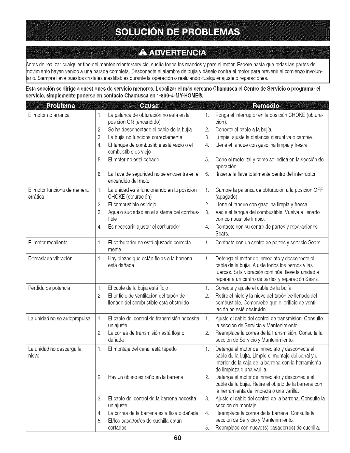
luier tipodel mantenimiento/servicio,sueltetodos los mandosy pare el motor.Esperehastaque todas las partesde
Ilevepuestoscristalesinastillablesdurantela operaci6no realizandocualquierajuste o reparaciones.
Estasecci6nse dirigea cuestione$de serviciomenores, Localizarel maccereanoChamuscael Centrode Servicio o programarel
servicio,simplementeponerseen contactoChamusca en 1-800-4-MY-HOME®.
El motor no arranca 1. /a palanea de obturacidn no estfi en la
posici6nON (encendido)
2. Se ha desconectadoel cablede la bujia
3. La bujia no funcionacorrectamente
4. El tanquede combustibleestervado o el
combustiblees viejo
5. El motorno estercebado
6. La Ilavede seguridadno se encuentraen el
encendidodel motor
1. La unidadesterfuncionandoen la posici6n
CHOKE(obturaci6n)
2. El combustibleesviejo
3. Aguao suciedaden el sistemadel combus-
tible
4. Es necesarioajustarel carburador
1. El carburadorno esterajustadocorrecta-
mente
1. Hay piezasque est_mflojaso la barrena
= = II •
1. Pongael interruptoren la posici6nCHOKE(obtura-
ci6n).
2. Conecteel cablea labujia.
3. Limpie,ajustela distanciadisruptivao cambie.
4. Lleneel tanquecongasolinalimpiay fresca.
5. Cebe el motortal y comose indicaenla secci6nde
operacibn.
6. Insertela Ilavetotalmentedentrodel interruptor.
1. Cambie la palancade obturaci6na la posici6nOFF
(apagado).
2. Lleneel tanquecongasolinalimpiay fresca.
3. Vacieel tanquedel combustible.Vuelvaa Ilenarlo
con combustiblelimpio.
4. Contactecon su centrode partesy reparaciones
Sears.
1. Contactecon un centrode partesy servicioSears.
El motorfuncionademanera
err_ttica
1. El cablede la bujiaesterflojo
2. El orificiode ventilaci6ndel tap6nde
Ilenadodel combustibleesterobstruido
El motorrecalienta
Demasiadavibraci6n
Perdidadepotencia
La unidadnose autopropulsa
La unidadnodescargala
nieve
1,
2.
1. Detengael motorde inmediatoy desconecteel
esterdahada cable dela bujia.Ajustetodoslos pernosy las
tuercas.Si la vibraci6ncontinOa,Ilevela unidada
reparara un centrode partesy reparaci6nSears.
1. Conectey ajusteel cablede labujia.
2. Retireel hieloy la nievedel tap6nde Ilenadodel
combustible.Compruebeque el orificiode venti-
laci6nnoeste obstruido.
Elcabledel controldetransmisi6nnecesita 1. Ajusteelcable delcontrolde transmisi6n.Consulte
unajuste
Lacorreadetransmisi6nesterflojao
dahada
1. El montajedel canalest_ttapado
2. Hay un objetoextrahoen la barrena
lasecci6ndeServicioy Mantenimiento.
2. Reemplacelacorreade latransmisi6n.Consultela
secci6nde Servicioy Mantenimiento.
1. Detengael motorde inmediatoy desconecteel
cable dela bujia. Limpieel montajedel canaly el
interiorde lacaja dela barrenacon laherramienta
de limpiezao unavarilla.
2. Detengael motorde inmediatoy desconecteel
cable dela bujia. Retireel objetode labarrenacon
la herramientadelimpiezao unavarilla.
3. Ajuste el cable del controlde la barrena.Consultela
secci6nde montaje.
4. Reemplacelacorreade labarrena Consultela
secci6nde Servicioy Mantenimiento.
5. Reemplacecon nuevo(s)pasador(es)de cuchilla.
3. El cabledel controlde la barrenanecesita
unajuste
4. La correade la barrenaest,. flojao dahada
5. El/los pasador/esde cuchillaest_m
cortados
6O
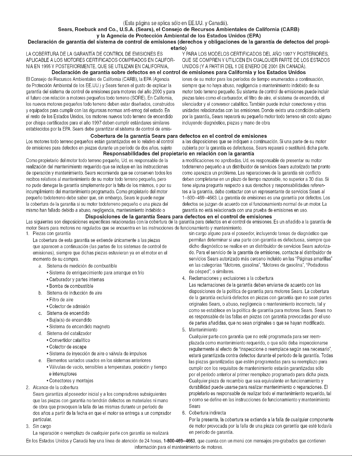
(Esta p_tginase aplica s61oen EE.UU. y CanadA).
Sears, Roebuck and Co., LI.S.Ao (Sears), el Coneejo de Recureoe Ambientalee de California (CARB)
y la Agencia de Protecci6n Ambiental de los Eetados Unidoe (EPA)
Declaracion de garant[a del sieterna de control de emisionee (derechoe y obmigacionee de la garant[a de defectoe del propi-
etario)
LA COBERTURADELA GARANTfADE CONTROLDE EMISIONESES
APLICABLEA LOSMOTORESCERTIFICADOSCOMPRADOSEN CALIFOR-
NIAEN 1995Y POSTERIORMENTE,QUE SE UTILIZANEN CALIFORNIA,
Declaracion de garantia sobre defectoe en el control
ElConsejode RecursosAmbientalesde California(CARB),la EPA(Agencia
de ProteccionAmbientalde los EE.UU.)y Searstienen el gustode explicarla
garantfadel sistemade controlde emisionespara motoresdel ado2000y para
elfuture con relaciona motorespequehostedo terreno(SORE).En California,
los nuevosmotorespequeSostodo terrenodebenestar diseSados,construidos
y equipadosparacumplirconlas rigurosasnormasanti-smogdelestado.En
el restede losEstadosUnidos,losmotoresnuevostodoterrenode encendido
perchispacertificadosparael aSo1997debencumplirestAndaressimilares
establecidosper la EPA.Searsdebegarantizarel sistemade controlde emis-
Y PARALOS MODELOSCERTIFICADOSDELAiqO 1997YPOSTERIORES,
QUESE COMPRENY UTILICENEN CUALQUIERPARTEDE LOSESTADOS
UNIDOS(YA PARTIRDEL 1 DE ENERODE2001 EN CANAD,_).
de emisionee para California y los Eetadoe Unidoe
ionesdesu motorparalosperiodosde tiempo enumeradosa continuaci6n,
siemprequeno hayaabuse,negligenciao mantenimientoindebidodesu
motortodoterrenopeque_o.Su sistemade controlde emisionespuedeincluir
piezastales comeel carburador,el filtrode aire, elsistemade encendido,el
silenciadory elconversercatalitico.Tambienpuedeincluirconectoresy otras
unidadesrelacionadascon las emisiones.Dondeexistaunacondicioncubierta
perla garantfa,Searsrepararasu peque_omotortodo terrenosincosto alguno
incluyendodiagnostico,piezasy manede obra
Cobertura de la garantia Sears para defectoe en el control de ernieionee
Los motorestodo terrenopeque_osestangarantizadosen Io relativealcontrol alas disposicionesque se indiquena continuacion.Si una partede su motor
de emisionesparadefectosenpiezas duranteun periodode dos ahos,sujeto cubiertaper la garantiaesdefectuosa,Sears repararao sustituiradichaparte.
Responeabilidadee del propietario en relacibn con la garantia
Comepropietariodel motortodo terrenopequeffo,Ud.es responsablede la
realizaciondel mantenimientorequeridoquese incluyeenlas instrucciones
de operaciony mantenimiento.Sears recomiendaquese conserventodoslos
recibosrelativesal mantenimientode su motortodoterrenopequeSo,pero
no pude denegarla garantfasimplementeperla faltade losmismos,o per su
incumplimientodel mantenimientoprogramado.Comepropietariodel motor
peque_otodoterrenodebesaberque, sinembargo,Sears lepuede negar
lacoberturade lagarantfasi su motortodoterrenopequeSoo una piezadel
mismehanfalladodebidoa abuse,negligencia,mantenimienteindebideo
a modificacienesno aprobadas.Ud.es responsablede presentarsu motor
todoterrenopequehoa un distribuidorde serviciosSearsautorizadotan pronto
comeaparezcaun problema.Lasreparacionesde la garantiasinconflicto
debencompletarseen un plazode tiempo razonable,no superiora 30 dfas.Si
tienealguna preguntarespectoa sus derechosy responsabilidadesreferen-
tes a la garantia,debe contactarcon un representantede serviciosSears al
1--800--469--4663.La garantiade emisioneses unagarantiaper defectos.Los
defectossejuzgan deacuerdocon elfuncionamientenormalde un motor.La
garantfano estarelacionadacon unapruebade emisionesen use.
Diepoeicionee de la garantia Sears para defectoe en el control de emieiones
Las siguientesson disposicionesespecificasrelacionadascon la coberturade la garantiaparadefectosen el controlde emisiones.Esun a_adidoa lagarantiade
motorSearspara motoresnoreguladesque seencuentraen lasinstruccionesde funcionamientoy mantenimiento.
1. Piezascon garantfa
La coberturade estagarantfase extiendeunicamentealas piezas
que aparecena continuacion(las partesde los sistemasde control de
emisiones),siemprequedichaspiezasestuvieranya enel motoren el
mementode su compra.
a. Sistemade medicion de combustible
• Sistemade enriquecimientopara arranqueen frio
• Carburadory partesinternas
• Bombade combustible
b. Sistemade induccionde aire
• Filtrode aire
• Colectorde admision
c. Sistemadeencendido
• Bujia(s)de encendido
• Sistemade encendidomagneto
d. Sistemadelcatalizader
• Convertidorcatalftico
• Colectorde escape
• Sistemade inyecci6nde aireo valvula deimpulses
e. Elementosvariadosusadosen los sistemasanteriores
• Valvulasde vacio,sensiblesa temperatura,posici6ny tiempo
e interruptores
• Conectoresy montajes
2. Alcancede la cobertura
Searsgarantiza alposeederinicialy a loscempradoressubsiguientes
que laspiezas con garantianotendran defectosen materialesnimane
de obra que provoquenla falla de las mismasduranteun periodo de
dos ahosa partirde la fecha en queel motorse entregaa un comprador
particular.
3. Sincargo
La reparaciono reemplazode cualquierpartecon garantfase realizara
sin cargoalguno parael poseedor,incluyendotareas de diagnosticoque
permitandeterminarsi una partecon garantiaes defectuosa,siempreque
dicho diagnosticose realiceen un distribuidorde serviciosSearsautoriza-
do. Parael serviciode lagarantia de emisiones,contacteal distribuidorde
serviciosSears autorizadomascercanoincluidoen las"Paginasamarillas"
en lascategoNas"Motores,gasolina","Motoresde gasolina","Podadoras
de cesped",o similares.
4. Reclamacionesy exclusionesa la cobertura
Las reclamacionesde lagarantfadebenenviarsedeacuerdocon las
disposicionesde la polfticade garantfapara motoresSears. La cobertura
de la garantiaexcluiradefectosen piezascon garantfaque no seanpartes
originalesSears,o abuse,negligenciao mantenimientoincorrecto,tal y
come se estableceen lapolitica de garantiapara motoresSears. Searsno
es responsablede lasfallas en piezascongarantia provocadasperel use
de partesa_adidas,que no sean originaleso que se hayanmodificado.
5. Mantenimiento
Cualquierpartecon garantiaque no este programadapara ser reem-
plazadacomemantenimientorequerido,o que solo deba inspeccionarse
regularmenteal efectode "inspeccioneo reemplacesegun sea necesario",
estaragarantizadacontra defectosduranteel periodo de la garantfa.Todas
las piezasgarantizadasqueesten programadasparasu reemplazopara
cumplir con los requisitesde mantenimientoestarangarantizadassolo
per el periodoanterioral primerreemplazoprogramadopara dicha pieza.
Cualquierpiezade recambioquesea equivalenteen funcionamientoy
durabilidadpuedeusarsepara realizarmantenimientoo reparaciones.El
propietarioes responsablede realizartodo el mantenimientorequerido,tal
y come sedefine en lasinstruccionesde funcionamientey mantenimiento
Sears
6. Ceberturaindirecta
Perla presente,la coberturase extiendea lafalla de cualquiercomponente
de motorprovocadaper lafalla de unapiezacon garantfaqueestetodavfa
en periodode garantfa.
En los EstadosUnidosy Canadahay unalinea de atenci6nde 24 horas,1-800=469--4663,quecuentacon un menL_con mensajespre-grabadosquecontienen
informacionpara el mantenimientode motores.
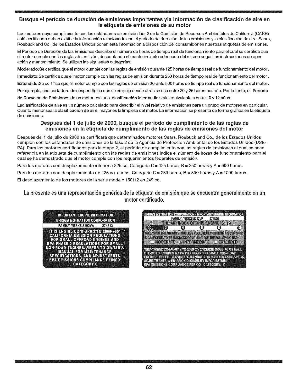
Busque el periodo de duracion de emisiones importantes yla informaci6n de clasificacion de aire en
la etiqueta de emisiones de su motor
Los motores cuyo cumplimiento con los est&ndares de emisi6n Tier 2 de la Comisi6n de Recursos Ambientales de California (CARB)
est6 certificado deben exhibir la informaci6n relacionada con el periodo de duraci6n de las emisiones y la clasificaci6n de aire. Sears,
Roebuck and Co., de los Estados Unidos ponen esta informaci6n a disposici6n del consumidor en nuestras etiquetas de emisiones.
El Pedodo de Duraci6n de las Emisiones describe el nQmero de horas de tiempo real de funcionamiento para el cual se certifica que
el motor cumple con las reglas de emisi6n, descontando el mantenimiento adecuado del mismo segQn las instrucciones de oper-
aci6n y mantenimiento. Se utilizan las siguientes categodas:
Moderado:Se certifica que el motor cumple con las reglas de emisi6n durante 125 horas de tiempo real de funcionamiento del motor.
Inmediato:Se certifica que el motor cumple con las reglas de emisi6n durante 250 horas de tiempo real de funcionamiento del motor.
Extendido:Se certifica que el motor cumple con las reglas de emisi6n durante 500 horas de tiempo real de funcionamiento del motor.
Por ejemplo, una cortadora de c6sped tipica que se empuja desde atr&s se usa entre 20 y 25 horas por afio. Por Io tanto, el Per{odo
de Duraci6n de Emisiones de un motor con una clasificaci6n intermedia seria equivalente a entre 10 y 12 afios.
Laclasificaci6n de aire es un nQmero calculado para describir el nivel relativo de emisiones para un grupo de motores en particular.
Cuanto menor sea la clasificaci6n de aire, mayor es la limpieza del motor. La informaci6n se presenta de forma gr&fica en la etiqueta
de emisiones.
Despu_s del 1 de julio de 2000, busque el per{odo de cumplimiento de las reglas de
emisiones en la etiqueta de cumplimiento de las reglas de emisiones del motor
Despu6s del I de julio de 2000 se certificar& que determinados motores Sears, Roebuck and Co., de los Estados Unidos
cumplen con los est&ndares de emisiones de la fase 2 de la Agencia de Protecci6n Ambiental de los Estados Unidos (USE-
PA). Para los motores certificados para la etapa 2, el periodo de cumplimiento con las reglas de emisiones al cual se hace
referencia en la etiqueta de cumplimiento con las reglas de emisiones indica el n_mero de horas de funcionamiento para el
cual se ha demostrado que el motor cumple con los requerimientos federales de emisi6n.
Para los motores con desplazamiento inferior a 225 cc, Categoria C = 125 horas, B = 250 horas y A = 500 horas.
Para los motores con desplazamiento de 225 cc o re&s, Categoria C = 250 horas, B = 500 horas y A = 1000 horas.
El desplazamiento de los motores de la serie modelo 150112 es 249 cc.
La presente es una representaci6n gen_rica de la etiqueta de emisi6n que se encuentra generalmenteen un
motor certificado.
62
Felicitacionespor haberrealizadouna adquisici6ninteligente.El
productoCraftsman@Profesionalquehaadquiridoest,.disehadoy
fabricadoparabrindarmuchosahos de funcionamientoconfiable.Pero
comotodoslos productosa vecespuede requerirde reparaciones.
Es enese momentocuandoel disponerde un Acuerdode protecci6n
parareparacionesle puedeahorrardineroy problemas.
Acontinuaci6nse detallanlos puntosincluidosen el Acuerdo:
• Servicio experto prestadopor nuestros10,000especialistasen
reparacionesprofesionales
Servicio ilimitadosin cargo paralas piezasy la manodeobraen
todaslas reparacionescubiertas
• Reemplazodel productohasta1500d61aressi noes posible
repararelproductocubierto
Descuentode 10%del precionormaldelservicioy de las piezas
relacionadascon el mismoquenoestencubiertasporel acuerdo;
adem_ts,10%del precionormalde laverificaci6nde manten-
imientopreventivo
• Ayuda r&pida portel_fono-Io IlamamosResoluci6nR_.pida-el
apoyotelef6nicode un Chamuscaal representante.Pienseen
nosotroscomoel manual"de unduehohablador."
Unavezadquiridoel Acuerdo,puedeprogramarel serviciocon
tan s61orealizaruna Ilamadatelef6nica.Puede Ilamaren cualquier
momentodel dia o de la nocheo programarun servicioen Ifnea.
ElAcuerdode Protecci6nde Reparaci6nes una comprasin riesgo.
Siustedanulapor algunaraz6nduranteel periodode garanfiade
producto,proporcionaremosun reembolsoIleno.O, unreembolso
prorrateadoen cualquiermomentodespuesdelperiodode garanfia
de productoexpira,iAdquierahoysu acuerdodeprotecci6npara
reparaciones!
Se aplican determinadaslimitacionesy exclusiones.Paraobtener
informaci6nadicional y preciosen losEstados UnidosIlame al
1-800-827-6655.
El*Coverage enCanad_var{aen algunos art{culos. Paradetalles
llenos la llamada ChamuscaCanad_en 1-800-361-6665.
Servicio de instalaci6nde Sears
Sideseasolicitarla instalaci6nprofesionalde Searsdeaparatos
dom_sticos,dispositivospara abrir portones,calentadoresde agua
y otrosarticulosdom_sticosimportantes,en los EstadosUnidoso
CanadaIlameal 1-800-4-MY-HOME@.
63

For expert home solutions advice: www.managemyhome.com
Our Home
For repair of carry-in items like vacuums, lawn equipment,
and electronics, call or go on-line for the location of your nearest
Sears Parts & Repair Service Center
1-800-488-1222 (U.S.A.) 1-800-469-4663 (Canada)
Call anytime, day or night
1-888-S U-HOGAR ®
(1-888-784-6427)
® Registered Trademark / TM Trademark / SM Service Mark of Sears Brands, LLC
® Marca Registrada / TMMarca de F_brica / s_ Marca de Servicio de Sears Brands, LLC
Mc Marque de commerce / MD Marque dCposCe de Sears Brands, LLC © Sears Brands, LLC


