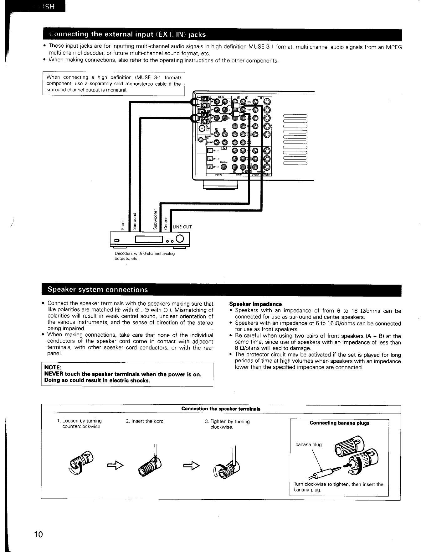
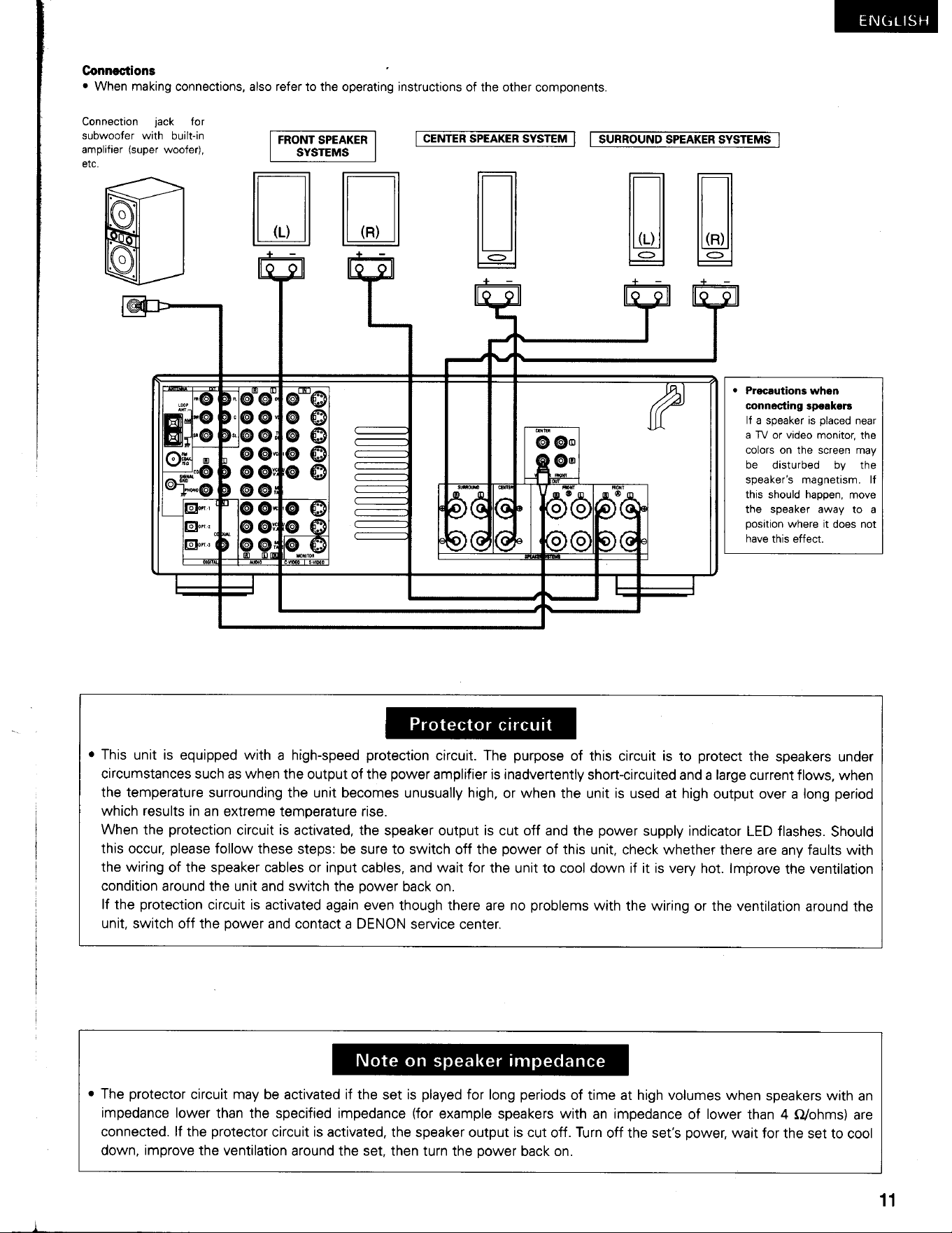
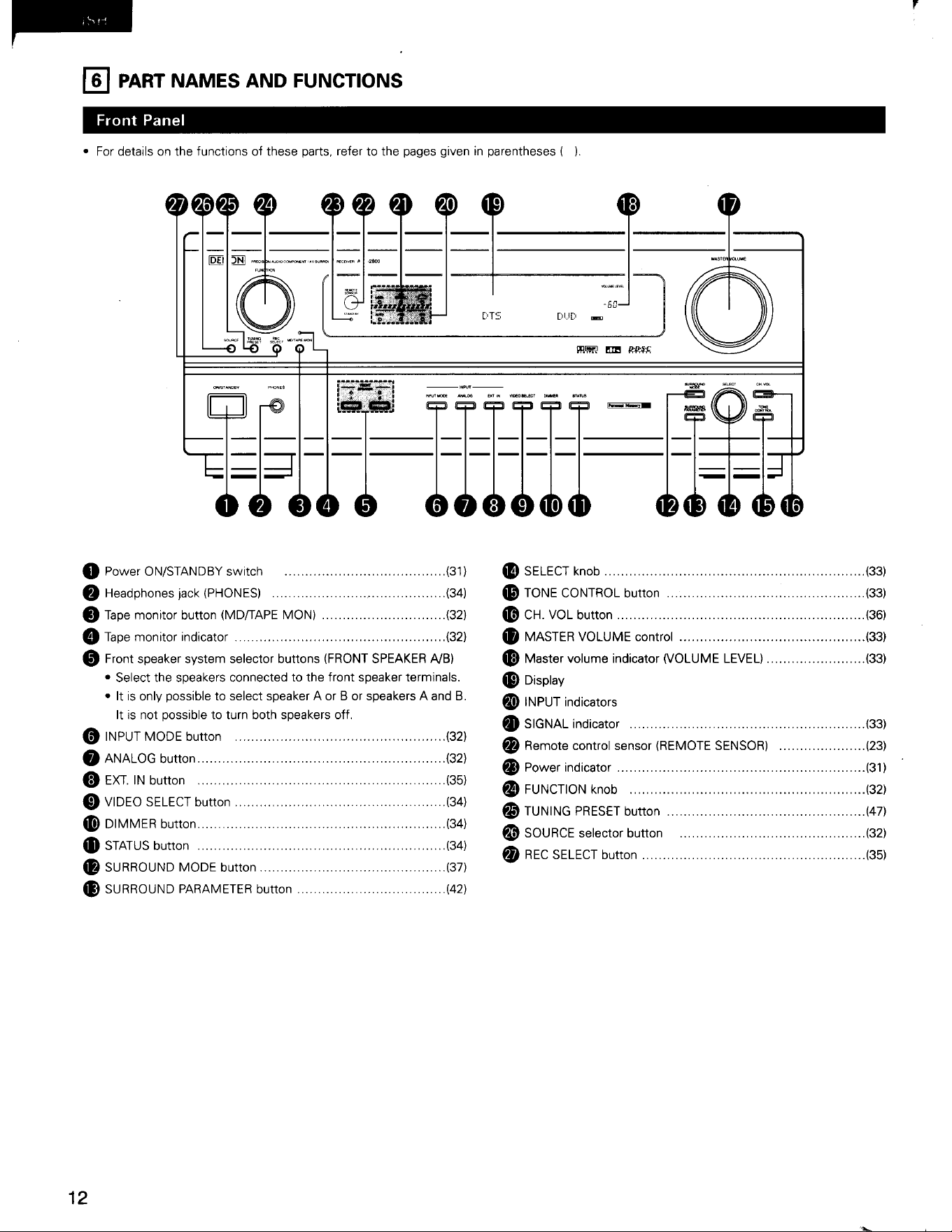
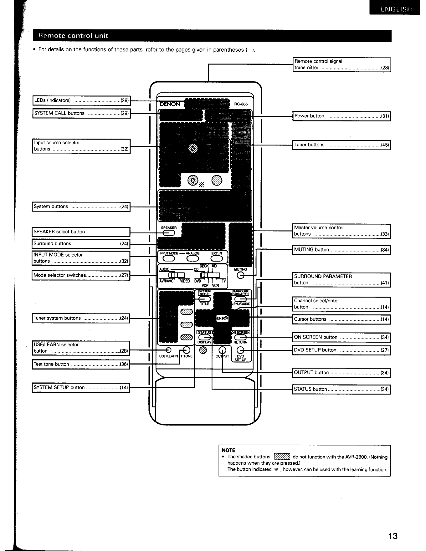
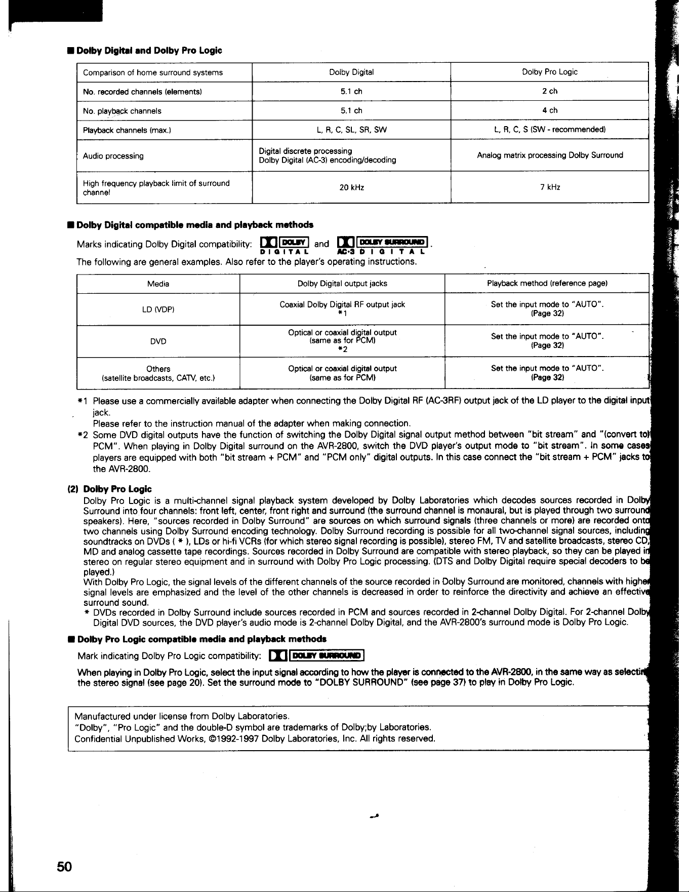
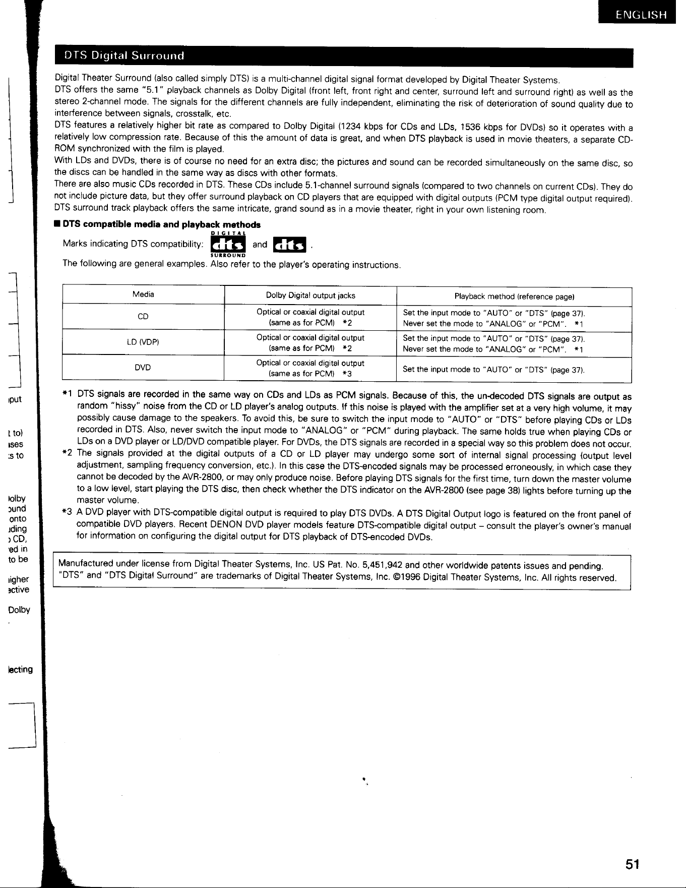
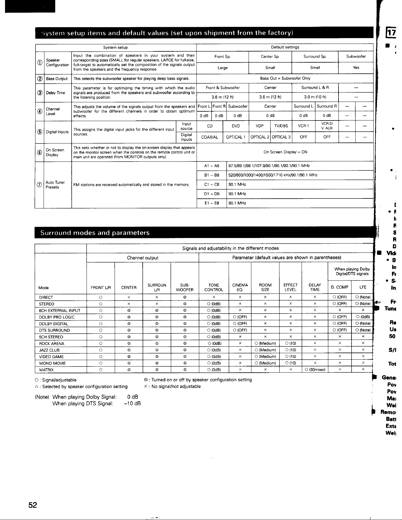
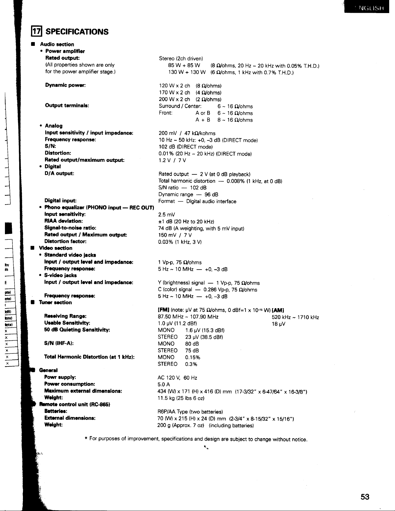
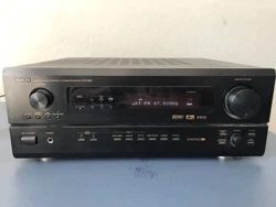
Denon AVR-2800 5.1 Channel AV Receiver with DTS, Dolby Digital, Pro Logic

Operating Instructions

For AVR-2800.

PDF File Manual, 53 pages, Read Online | Download pdf file

AVR-2800 photo
background
Loading page 2...
Loading page 3...
Loading page 4...
Loading page 5...
Loading page 6...
Loading page 7...
Loading page 8...
Loading page 9...
Loading page 10...
Loading page 11...
Loading page 12...
Loading page 13...
Loading page 14...
Loading page 15...
Loading page 16...
Loading page 17...
Loading page 18...
Loading page 19...
Loading page 20...
Loading page 21...
Loading page 22...
Loading page 23...
Loading page 24...
Loading page 25...
Loading page 26...
Loading page 27...
Loading page 28...
Loading page 29...
Loading page 30...
Loading page 31...
Loading page 32...
Loading page 33...
Loading page 34...
Loading page 35...
Loading page 36...
Loading page 37...
Loading page 38...
Loading page 39...
Loading page 40...
Loading page 41...
Loading page 42...
Loading page 43...
Loading page 44...
Loading page 45...
Loading page 46...
Loading page 47...
Loading page 48...
Loading page 49...
Loading page 50...
Loading page 51...
Loading page 52...
Loading page 53...

Other documents for Denon AVR-2800

The following documents are available:
User Manual Specification Photos

Specifications

Operating Instructions - Transcript

  • Page 1 - English - : AV SURROUND RECEIVER RECEPTEUR AUDIO-VIDEO OPERATING INSTRUCTIONS MODE D’EMPLOI mecmpingocounnen sesimeve ere: fh FOR ENGLISH READERS PAGE 2~ PAGE 53 POUR LES LECTEURS FRANCAIS PAGE 2. 4~ PAGE 103 H We greatly appreciate your purchase of the AVR-2800. H To be sure you take maximum advantage of all the features the AVR-2800 has to offer. read these instructions carefully and use the set properly. Be sure to keep this manual for future reference should any questions or problems arise. @ Nous vous remercions de |’achat de lAVR-2800. @ Pour étre sar de profiter au maximum de toutes les caractéristiques qu’a a offrir ' AVR-2800. lire avec soin ces instructions et bien utiliser l'appareil. Toujours conserver ce mode d’emploi pour sy référer ultérieurement en cas de question ou de probléme.
  • Page 2 - English - : @ SAFETY PRECAUTIONS TO PREVENT FIRE OR SHOCK HAZARD. DO NOT EXPOSE TO PREVENT ELECTRIC SHOCK DO NOT USE THIS THIS APPLIANCE TO RAIN OR MOISTURE. (POLARIZED) PLUG WITH AN EXTENSION CORD. RECEPTACLE OR OTHER OUTLET UNLESS THE BLADES CAN BE FULLY INSERTED TO PREVENT BLADE EXPOSURE. = RISK OF ELECTRIC SHOCK DO NOT OPEN CAUTION: To REDUCE THE RISK OF ELECTRIC SHOCK. DO NOT REMOVE COVER (OR BACK). NO USER SERVICEABLE PARTS INSIDE. REFER SERVICING TO QUALIFIED SERVICE PERSONNEL. The lightning flash with arrowhead symbol. within an equilateral triangle. is intended to alert the user to the presence of uninsulated “dangerous voltage” within the product's enclosure that may be of sufficient magnitude to constitute a risk of electric shock to ¢ POUR LES MODELE CANADIEN UNIQUEMENT: POUR PREVENIR LES CHOCS ELECTRIQUES NE PAS UTILISER CETTE FICHE POLARISEE AVEC UN PROLONGATEUR UNE PRISE DE COURANT OU UNE AUTRE SORTIE DE COURANT. SAUF SI LES LAMES PEUVENT ETRE INSEREES A FOND SANS EN LAISSER AUCUNE PARTIE A DECOUVERT. This device complies with Part 15 of the FCC Rules. Operation is subject to the following two conditions: (1) This device may not cause harmful interference. and (2) this device must accept any interference received. including interference that may cause undesired operation. The exclamation point within an equilateral triangle is intended to alert the user to the presence of This Class B digital apparatus meets all requirements of the Canadian Interference-Causing Equipment Regulations. important operating and maintenance (servicing) instructions in the literature accompanying the appliance. Cet appareil numérique de la classe B respecte toutes les exigences du Reglement sur le matériel brouilleur du Canada. “SERIAL NO. PLEASE RECORD UNIT SERIAL NUMBER ATTACHED TO THE REAR OF THE CABINET FOR FUTURE REFERENCE” “NO. DE SERIE PRIERE DE NOTER LE NUMERO DE SERIE DE LAPPAREIL INSCRIT A L’ARRIERE DU COFFRET DE FACON A POUVOIR LE CONSULTER EN CAS DE PROBLEME.” M@ NOTE ON USE / OBSERVATIONS RELATIVES A L’UTILISATION » * Keep the set free from moisture. water. and * Ne pas laisser des objets étrangers dans dust. l'appareil. © Protéger l'appareil contre Ihumidité. l'eau et lapoussiére. AGH) ue ' 7 * Do not let foreign objects in the set. eax ot let foreign obje e se ¢ Avoid high temperatures. Allow for sufficient heat dispersion when installed on a rack. Eviter des températures élevées Tenir compte d'une dispersion de chaleur suffisante lors de |'installation sur une étagére. Do not let insecticides. benzene. and thinner come in contact with the set. Unplug the power cord when not using the set Ne pas mettre en contact des insecticides. du for long periods of time. benzéne et un diluant avec l'appareil. Débrancher le cordon d’alimentation lorsque l'appareil n'est pas utilisé pendant de longues Handle the power cord carefully. Hoid the plug when unplugging the cord. Manipuler le cordon d'alimentation avec précaution. Tenir la prise lors du débranchement du * (For sets with ventilation holes) Never disassemble or modify the set in any Do not obstruct the ventilation holes. Ne jamais démonter ou modifier l'appareil Ne pas obstruer les trous d’aération. dune maniére ou d'une autre.
  • Page 3 - English - : SAFETY INSTRUCTIONS Read Instructions — All the safety and operating instructions 12. should be read before the appliance is operated. Retain Instructions — The safety and operating instructions should be retained for future reference. Heed Warnings — All warnings on the appliance and in the 14. operating instructions should be adhered to. Follow Instructions — All operating and use instructions 15 should be followed. Water and Moisture - The appliance should not be used 16. near water — for example. near a bathtub. washbowl. kitchen sink. laundry tub. in a wet basement. or near a swimming pool. and the like. Carts and Stands — The appliance should be used only with a cart or stand that is recommended by the manufacturer. An appliance and cart combination should be moved with care. Quick stops. excessive force. and uneven surfaces may cause the appliance and cart combination to overturn. Wall or Ceiling Mounting - The appliance should be 18. mounted to a wall or ceiling only as recommended by the manufacturer. Ventilation - The appliance should be situated so that its 19. location or position does not interfere with its proper ventilation. For example. the appliance should not be situated on a bed. sofa. rug. or similar surface that may block the ventilation openings; or. placed in a built-in installation. such as a bookcase or cabinet that may impede the flow of air through the ventilation openings. Heat — The appliance should be situated away from heat sources such as radiators. heat registers. stoves. or other appliances (including amplifiers) that produce heat. Power Sources - The appliance should be connected to a power supply only of the type described in the operating 20. instructions or as marked on the appliance. Grounding or Polarization — Precautions should be taken so that the grounding or polarization means of an appliance is not defeated. EXAMPLE OF ANTENNA GROUNDING AS PER NATIONAL ELECTRICAL CODE DISCHARGE UNIT (NEC SECTION 810-20) (NEC SECTION 810-21) GROUND CLAMPS POWER SERVICE GROUNDING tt ELECTRODE SYSTEM (NEC ART 250. PART H) NEG - NATIONAL ELECTRICAL CODE Power-Cord Protection - Power-supply cords should be routed so that they are not likely to be walked on or pinched by items placed upon or against them. paying particular attention to cords at plugs. convenience receptacles. and the point where they exit from the appliance. Cleaning — The appliance should be cleaned only as recommended by the manufacturer. Power Lines — An outdoor antenna should be located away from power lines. Outdoor Antenna Grounding —- If an outside antenna is connected to the receiver. be sure the antenna system is grounded so as to provide some protection against voltage surges and built-up static charges. Article 810 of the National Electrical Code. ANSI/NFPA 70. provides information with regard to proper grounding of the mast and supporting structure. grounding of the lead-in wire to an antenna-discharge unit. size of grounding conductors. location of antenna-discharge unit. connection to grounding electrodes. and requirements for the grounding electrode. See Figure A. Nonuse Periods — The power cord of the appliance should be unplugged from the outlet when left unused for a long period of time. Object and Liquid Entry — Care should be taken so that objects do not fall and liquids are not spilled into the enclosure through openings. Damage Requiring Service - The appliance should b serviced by qualified service personnel when: A. The power-supply cord or the plug has been damaged; or B. Objects have fallen. or liquid has been spilled into the appliance; or C. The appliance has been exposed to rain; or D. The appliance does not appear to operate normally or exhibits a marked change in performance; or E. The appliance has been dropped. or the enclosure Servicing — The user should not attempt to service the appliance beyond that described in the operating instructions. All other servicing should be referred to qualified service personnel.
  • Page 4 - English - : @ INTRODUCTION Thank you for choosing the DENON AVR-2800 Digital Surround A/V receiver. This remarkable component has been engineered to provide superb surround sound listening with AV theater sources such as DVD. as well as providing outstanding high fidelity reproduction of your favorite music As this product is provided with an immense. array af feptures. we recommend thet before you begin hookup and operation that you review the Sortantn of 2s rae ere a Mist. anianouy TABLE OF CONTENTS m@ ACCESSORIES Check that the following parts are included in addition to the main unit: ® R6P/AA batteries © AM loop antenna 1 @ FM indoor antenna...1 FM antenna adaptor . (RC-865) [1] BEFORE USING Pay attention to the following before using this unit: * Moving the set ¢ Store this instructions in a safe place. To prevent short circuits or damaged wires in the connection cords. After reading. store this instructions along with the warranty in a always unplug the power cord and disconnect the connection cords safe place. between all other audio components when moving the set. . . . : . P g ¢ Note that the illustrations in this instructions may differ from Before turning the power switch on the actual set for explanation purposes. Check once again that all connections are proper and that there are not problems with the connection cords. Always set the power switch to the standby position before connecting and disconnecting connection cords. [2] CAUTIONS ON INSTALLATION Noise or disturbance of the picture may be generated if this unit or any other electronic equipment using microprocessors is used near a tuner or TV. If this happens. take the following steps: e Install this unit as far as possible from the tuner or TV. e Set the antenna wires from the tuner or TV away from this unit's power cord and input/output connection cords. TET Ti © Noise or disturbance tends to occur particularly when using indoor antennas or 300 Q/ohms feeder wires. We recommend using 10 cm or more outdoor antennas and 75 2/ohms coaxial cables. * 10cm or more For heat dispersal. leave at least 10 cm of space between the top. back and sides of this unit and the wall or other components. Wall
  • Page 5 - English - : [3] CAUTIONS ON HANDLING Switching the input function when input jacks are not A clicking noise may be produced if the input function is switched when nothing is connected to the input jacks. If this happens. either turn down the MASTER VOLUME control or connect components to the input jacks. Muting of PRE OUT jacks. HEADPHONE jack and SPEAKER The PRE OUT jacks. HEADPHONE jacks and SPEAKER terminals include a muting circuit. Because of this. the output signals are greatly reduced for several seconds after the power switch is turned on or input function. surround mode or any other-set-up is changed. If the volume is turned up during this time. the output will be very high after the muting circuit stops functioning. Always wait until the muting circuit turns off before adjusting the volume. [4] FEATURES Dolby Digital Using advanced digital processing algorithms. Dolby Digital provides up to 5.1 channels of wide-range. high fidelity surround sound. Dolby Digital is the default digital audio delivery system for North American DVD and DTV. DTS (Digital Theater Systems} DTS provides up to 5.1 channels of wide-range. high fidelity surround sound. from sources such as laser disc. DVD and specially-encoded music discs. e Whenever the power switch is in the STANDBY state. the apparatus is still connected on AC line voltage. Please be sure to unplug the cord when you leave home for. say. a vacation. 3. 24 bit D/A Conversion All six channels. including the five main channels and the low frequency effects (LFE) channel benefit from reference. for optimum high fidelity reproduction of music and movie soundtracks. Video Select Function Allow you to watch one source (visual) while listening to another source (audio).
  • Page 6 - English - : [5] CONNECTIONS ¢ Do not plug tn the AC cord until all connections have been completed. * Be sure to connect the left and right channels properly (left with left. right with right). * insert the plugs securely. Incomplete connections will result in the generation of noise. ¢ Use the AC OUTLETS for audio equipment only. Do not use them for hair driers. etc. * Note that binding pin plug cords together with AC cords or placing them near a power transformer will result in generating hum or other noise. ¢ Noise or humming may be generated if a connected audio equipment is used independently without turning the power of this unit on. If this happens. turn on the power of the this unit. Connecting the audio components ¢ When making connections. also refer to the operating instructions of the other components. The power to these outlets is turned on and off when the power is switched between on and standby from the remote control unit or power switch. Connecting a CD player Connect the CD player's analog output jacks (ANALOG OUTPUT) to this unit's CD jacks using pin plug cords. Connecting a turntable Connect the turntable’s output cord to the AVR-2800's PHONO jacks. the L (left) plug to the L jack. the R (right) plug to the right This unit cannot be used with MC ; . Connecting the pre-out jacks cartridges directly. Use a separate head ) amplifier or step-up transformer. If humming or other noise is generated when the ground wire is connected. disconnect the ground wire. terminal. (Refer to page 11.) (MM cartridge) MD recorder. DAT deck or other component equipped with digital output jacks ea 0=SSa( =) S28 4 oo sscecsce OOOO a = OPTICAL er (} CD player or other OP COAXIA component equipped A c OUTPUT with digital output jacks INPUT OUTPUT Connecting the DIGITAL jacks Use these for connections to audio equipment with digital output. Refer to page 20. 21 for instructions on setting this terminal. * Use 75 Q/ohms cable pin cords for coaxial connections. e Use optical cables for optical connections. removing the cap before connecting. Use these jacks if you wish to connect external power amplifier(s) to increase the power of the front and center channels. or for connection to powered loudspeakers. Connect the internal amplifier's subwoofer to the subwoofer Connecting the AC OUTLTETS AC OUTLETS ¢ SWITCHED (total capacity — 120 W (1 A.) The power to these outlets is turned on and off in conjunction with the POWER operation switch on the main unit. and when the power is switched between on and standby from the remote control unit. No power is supplied from these outlets when this unit’s power is at standby. Never connect equipment whose total capacity is above 120 W (1A). Only use the AC OUTLETS for audio equipment. Never use them for hair driers. TVs or other electrical appliances. AC 120 V. 60 Hz Route the connection cords. etc. in such a way that they do not obstruct the ventilation holes. Tape deck or MD recorder Connecting a tape deck Connections for recording: Connect the tape deck’s recording input jacks (LINE IN or REC) to this unit's tape recording (MD/TAPE OUT) jacks using pin plug cords. Connections for playback: Connect the tape deck’s playback output jacks (LINE OUT or PB) to this unit’s tape playback (MD/TAPE IN) jacks using pin plug cords.
  • Page 7 - English - : a OTM bare Connecting video components ¢ To connect the video signal. connect using a 75 Q/ohms video signal cable cord. Using an improper cable can result in a drop in video quality. ¢ When making connections. also refer to the operating instructions of the other components. TV or DBS tuner Connecting a TV/DBS tuner ¢ Connect the TV's or DBS tuner’s video output jack (VIDEO OUTPUT) to the R ot OUT Monitor TV Go @ © (yellow) TV/DBS IN jack using a 75 Q/ohms video coaxial pin plug cord. vy 7 * Connect the TV's or DBS tuner’'s audio output jacks (AUDIO OUTPUT) to the 7. = TV/DBS IN jacks using pin plug cords. a 3 MONITOR OUT : : § *Connect the TV's video a : input jack (VIDEO INPUT) a our LD player. CDV player. etc.. to the DMDEO} MONITOR J @© @ @ : OUT Jack using a 78 alolll s Q/ohms video coaxial pin | : VV \ tpl cord. See pages 21 " s ¢ Connect the video disc player's video output jack (VIDEO OUTPUT) to the (yellow) 8 a VDP/DVD IN jack using a 75 Q/ohms video coaxial pin plug cord. ' : s © Connect the video disc player's analog audio output jacks (ANALOG AUDIO OUTPUT) to the | . : VDP/DVD IN jacks using pin plug cords. : = * A DVD player can be connected to the DVD jacks in the same way. s ; ° tis also possible to connect a video disc player. DVD player. video camcorder. game machine. : | 7 : etc. to the VCR-2/V.AUX jacks. s J | em connneneecensenet oon : | Oster ne. a os Note on connecting the digital input jacks i Sate * Only audio signals are input to the digital input jacks. mo eeesneeneemoneon steele sy For details. see page 6. Video deck 2 o 5 fPoeeeo nen eeee : ¢ There are two sets of video deck (VCR) jacks. so two video decks can be connected for simultaneous recording or video copying. Video input/output connections: * Connect the video deck’s video output jack (VIDEO OUT) to the [VIDEO] (yellow) VCR-1 IN jack. and the video deck’s video input jack (VIDEO IN) to the [VIDEO] (yellow) VCR-1 OUT jack using 75 Q/ohms video coaxial pin plug cords. Connecting the audio output jacks ¢ Connect the video deck’s audio output jacks (AUDIO OUT) to the VCR-1 IN jacks. and the video decks audio input jacks (AUDIO IN) to the VCR-1 OUT jacks using pin plug cords. * Connect the second video deck to the VCR-2/V.AUX jacks in the same way.
  • Page 8 - English - : Connecting a video component equipped with S-Video jacks e When making connections. also refer to the operating instructions of the other components. * Anote on the S input jacks The input selectors for the S inputs and pin jack inputs work in conjunction with each other. ¢ Precaution when using S-jacks This unit's S-jacks (input and output) and video pin jacks (inout and output) have independent circuit structures. so that video signals input from the S-jacks are only output from the S-jack outputs and video signals input from the pin jacks are only output from the pin jack outputs. When connecting this unit with equipment that is equipped with S-jacks. keep the above point in mind and make connections according to the equipment'’s instruction manuals. Connecting a monitor TV LD player. CDV player. etc. MONITOR OUT e¢ Connect the TV's or DBS tuner’s S video input (S-VIDEO INPUT) to the MONITOR OUT-1 jack using a S jack connection cord. Connecting a video disc player (VDP) * Connect the video disc player's S-Video output jack to the S- e Monitor TV VIDEO VDP IN jack using an S-Video connection cord. as e A DVD player can be connected to the DVD jacks in the same = way. Connecting a TV/DBS tuner ® It is also possible to connect a video disc player. DVD player. video camcorder. game machine. etc. to the VCR-2/V.AUX ¢ Connect the TV's or DBS tuner’s S video output jack (S-VIDEO OUTPUT) to the TV/DBS IN jack using an S jack connection cord. Oneaeeneesskerenas GD Video deck 1 Connecting the video decks * Connect the video deck’s S output jack (S-OUT) to the VCR-1 IN jack and the video deck's S input jack (S-IN) to the VCR-1 OUT jack using S$ jack connection cords. CB ned Seuseesvaanessaas ie Oa ON paesvnee VnsasenscsasessQy | « D e Connect the video deck’s S output jack (S-OUT) to the VCR-2/V.AUX IN jack and the video deck’s S input jack (S-IN) to the VCR-2/V.AUX OUT jack using S jack connection cords. wi SRBERRERSRSAAH ERE Video deck 2
  • Page 9 - English - : Connecting the antenna terminals DIRECTION OF BROADCASTING STATION AM LOOP ~~ (An Accessory) FM ANTENNA 75 Q/ohms EAS COAXIAL FEEDER Qe CABLE CABLE FM ANTENNA {An Accessory) (An Accessory) ors GK IE € Ee) TaTAL O Cree y?| e An F-type FM antenna cable plug can be connected directly. lf the FM antenna cable's plug is not of the F-type. connect using the included antenna adapter. AM loop antenna assembly Connect to the AM antenna terminals. Remove the B tie and take out the Bend in the reverse @ connection line. direction. 75 Qfohms COAXIAL CABLE ANTENNA ADAPTER a. With the antenna on top any stable b. With the antenna attached to a wall. Installation hoie Mount on wall. etc. 75 Qfohms COAXIAL CABLE Connection of AM antennas 1. Push the lever. 2. Insert the conductor. 3. Return the lever. my > thy > an) Note to CATV system installer: This reminder is provided to call the CATV system installer’s attention to Article 820-40 of the NEC which provides guidelines for proper grounding and. in particular. specifies that the cable ground shall be connected to the grounding system of the building. as close to the point of cable entry as practical. ¢ Do not connect two FM antennas simultaneously. ¢ Even if an external AM antenna is used. do not disconnect the AM loop antenna. © Make sure AM loop antenna lead terminals do not touch metal parts of the panel.
  • Page 10 - English - : onnecting the external input (EXT. IN) jacks ¢ These input jacks are for inputting multi-channel audio signals in high definition MUSE 3-1 format. multi-channel audio signals from an MPEG multi-channel decoder. or future multi-channel sound format. etc. * When making connections. also refer to the operating instructions of the other components. When connecting a high definition (MUSE 3-1 format) component. use a separately sold mono/stereo cable if the surround channel output is monaural. Decoders with 6-channet analog outputs. etc. Speaker system connections Speaker Impedance ¢ Speakers with an impedance of from 6 to 16 Q/ohms can be connected for use as surround and center speakers. ¢ Connect the speaker terminals with the speakers making sure that like polarities are matched (© with © . © with © ). Mismatching of polarities will result in weak central sound. unclear orientation of the various instruments. and the sense of direction of the stereo ¢ Speakers with an impedance of 6 to 16 Q/ohms can be connected being impaired. for use as front speakers. e¢ When making connections. take care that none of the individual ¢ Be careful when using two pairs of front speakers (A + B) at the conductors of the speaker cord come in contact with adjacent terminals. with other speaker cord conductors. or with the rear NEVER touch the speaker terminals when the power is on. Doing so could result in electric shocks. same time. since use of speakers with an impedance of jess than 8 Q/ohms will lead to damage. The protector circuit may be activated if the set is played for long periods of time at high volumes when speakers with an impedance lower than the specified impedance are connected. Connection the speaker terminals 1. Loosen by turning 2. Insert the cord. counterclockwise 3. Tighten by turning clockwise. Connecting banana plugs Turn clockwise to tighten. then insert the banana plug. banana plug
  • Page 11 - English - : Connections ¢ When making connections. also refer to the operating instructions of the other components. Connection jack for subwoofer with built-in FRONT SPEAKER CENTER SPEAKER SYSTEM SURROUND SPEAKER SYSTEMS amplifier (super woofer). le! (R) (U) (R) Precautions when connecting speakers If a speaker is placed near a TV or video monitor. the colors on the screen may be disturbed by the speaker’s magnetism. If this should happen. move the speaker away to a position where it does not have this effect. Protector circuit ¢ This unit is equipped with a high-speed protection circuit. The purpose of this circuit is to protect the speakers under circumstances such as when the output of the power amplifier is inadvertently short-circuited and a large current flows. when the temperature surrounding the unit becomes unusually high. or when the unit is used at high output over a long period which results in an extreme temperature rise. When the protection circuit is activated. the speaker output is cut off and the power supply indicator LED flashes. Should this occur. please follow these steps: be sure to switch off the power of this unit. check whether there are any faults with the wiring of the speaker cables or input cables. and wait for the unit to cool down if it is very hot. Improve the ventilation condition around the unit and switch the power back on. If the protection circuit is activated again even though there are no problems with the wiring or the ventilation around the unit. switch off the power and contact a DENON service center. Note on speaker impedance ¢ The protector circuit may be activated if the set is played for long periods of time at high volumes when speakers with an impedance lower than the specified impedance (for example speakers with an impedance of lower than 4 Q/ohms) are connected. If the protector circuit is activated. the speaker output is cut off. Turn off the set’s power. wait for the set to cool down. improve the ventilation around the set. then turn the power back on.
  • Page 12 - English - : [6] PART NAMES AND FUNCTIONS Front Panel e For details on the functions of these parts. refer to the pages given in parentheses (_ ). MASTER) UME VEO SELECT = DIMMER STATUS e Headphones jack (PHONES) ....... 0... cece cece enc nee ee ee enna en es (34) 0 TEE: FEST WERE seem 1 cases + 6 een 9 eomcnes 1 ren 2 enone 9 erm A (32) o Front speaker system selector buttons (FRONT SPEAKER A/B) e Select the speakers connected to the front speaker terminals. ® It is only possible to select speaker A or B or speakers A and B. It is not possible to turn both speakers off. @ ANALOG button... cc ee ettteneteees (32) @ EXTIN button ccc cette ttttettenenees (35) @ VIDEO SELECT button ooo. eee teteteteeteneen (34) QD DIMMER button... cect cee ctetetteneeen (34) @ STATUS button ccc ttttetteneeee (34) @ SURROUND MODE button 0.0... (37) @® SURROUND PARAMETER button ...0....cc cc ceceeeeeeeeee (42) @® TONE CONTROL button oo... eeeseees (33) QB CH. VOL button ooo cece cece esertseseetenenenin (36) @ INPUT indicators @ SIGNAL indicator ....... 0... ceeeeees reece neeen eee eeeeneeenes (33) @ Remote control sensor (REMOTE SENSOR) ...........:::.00008 (23)
  • Page 13 - English - : a LOG beta Remote control unit ¢ For details on the functions of these parts. refer to the pages given in parentheses (_ ). Remote control signal LEDs (indicators) Input source selector Tuner buttons Master volume contro! MUTING button SURROUND PARAMETER AUDIO ————--—- CD H | " AVR/IAVC) = VIDEO —DVD WV Channel select/enter Tuner system buttons Cursor buttons ON SCREEN button USE/LEARN selector DVD SETUP button Test tone button OUTPUT button SYSTEM SETUP button oo... STATUS button ° The shaded buttons (77 do not function with the AVR-2800. (Nothing happens when they are pressed.) The button indicated %. however. can be used with the learning function.
  • Page 14 - English - : [7] SETTING UP THE SYSTEM ¢ Once all connections with other AV components have been completed as described in “CONNECTIONS” (see pages 6 to 11). make the various settings described below on the monitor screen using the AVR-2800's on-screen display function. These settings are required to set up the listening room's AV system centered around the AVR-2800. e Use the following buttons to set up the system: Press this to display the system setup menu. SURROUND PARAMETER button Press this to display the surround parameter menu. Press this to switch the display on the screen. Also use this button to complete the setting on the screen. CURSOR buttons Use these to move the cursors (<4 and B) to the left and right on the screen. Use these to move the cursors (A and ¥) up and down on the ¢ System setup items and default values (set upon shipment from the factory) System setup Default settings Configuration | full-range) to automatically set the composition of the signals output |@ | Bass Output | This selects the subwoofer speaker for playing deep bass signals. Bass Out = Subwoofer Only This parameter is for optimizing the timing with which the audio Front & Subwoofer Surround L & R p= | Delay Time signals are produced from the speakers and subwoofer according to the listening position. 3.6 m (12 ft} 3.6 m (12 ft) 3.0 m (10 ft) Fo @ Level subwoofer for the different channels in order to obtain optimum Input : VCR-2/ ross [ens | Sa | — | | ae COAXIAL | OPTICAL 1 } OPTICAL 2] OPTICAL 3 | ore | or | — | = | This sets whether or not to display the on-screen display that appears on the monitor screen when the controls on the remote control unit or main unit are operated (from MONITOR outputs only). Input the combination of speakers in your system and their Speaker corresponding sizes (SMALL for regular speakers. LARGE for full-size. This assigns the digital input jacks for the different input Digital Inputs anurees. On Screen Display = ON Sea FM stations are received automatically and stored in the memory. c1~C8 90.1 MHz D1 ~ D8 90.1 MHz e The on-screen display signals are output with priority to the S-VIDEO MONITOR OUT jack during playback of a video component. For example. if the TV monitor is connected to both the AVR-2800's S-Video and video monitor output jacks and signals are input to the AVR-2800 from a video source (VDP. etc.) connected to both the S-Video and video input jacks. the on-screen display signals are output with priority to the SVideo monitor output. If you wish to output the signals to the video monitor output jack. do not connect a cord to the S-VIDEO MONITOR OUT jack. (For details. see page 22.) The AVR-2800’s on-screen display function is designed for use with high resolution monitor TVs. so it may be difficult to read small characters on TVs with small screens or low resolutions. The setup menu is not displayed when “HEADPHONE ONLY” is selected.
  • Page 15 - English - : Speaker system layout Basic system layout e The following is an example of the basic layout for a system consisting of six speaker systems and a television monitor: Subwoofer Center speaker system Front speaker systems Set these at the sides of the TV or screen with their front surfaces as flush with the front of the screen as possible Surround speaker systems Before setting up the system 1 Check that all the connections are correct. then turn on the main unit's power. 2 Display the System Setup Menu. Serur System Setup Menu wSpeaker Configuration cat vBass Output Delay Time Channel Level Digital Inputs On Screen Display Auto Tuner Presets Setting the type of speakers e The composition of the signals output from the different channels and the frequency response are adjusted automatically according to the combination of speakers actually being used. 1 At the System Setup Menu select “Speaker Configuration”. 2 Switch to the speaker configuration screen.
  • Page 16 - English - : Set whether or not speakers are connected and. if so. their size [+\ parameters. e To select the speaker © To select the parameter Enter the setting. The System Setup Menu reappears. Surround Sp. Speaker Configuration e Select “Large” or “Small” not according to the actual size of the speaker but according to the speaker's capacity for playing low frequency (approximately 80 Hz and below) signals. If you do not know. try comparing the sound at both settings (setting the volume to a level low enough so as not to damage the speakers) to determine the proper setting. ¢ Parameters Large...... Select this when using speakers that can fully reproduce low sounds of below 80 Hz. Small...... Select this when using speakers that cannot reproduce low sounds of below 80 Hz with sufficient volume. When this setting is selected. low frequencies of below 80 Hz are assigned to the subwoofer. None...... Select this when no speakers are installed. Yes/No.... Select “Yes” when a subwoofer is installed. “No” when a subwoofer is not installed. * If the subwoofer has sufficient low frequency playback capacity. good sound can be achieved even when “Small” is set for the front. center and surround speakers. * For the majority of speaker system configurations. using the SMALL setting for all five main speakers and Subwooofer On with a connected subwoofer will yield the best results. 1 At the System Setup Menu select “Bass Output”. Setting the bass output System Setup Menu aSpeaker Configuration @Bass Output vwDelay Time Channel Level Digital Inputs On Screen Display Auto Tuner Presets 2 Switch to the Bass Output screen. Bass Output
  • Page 17 - English - : ea LCT tela 3 Select the bass signal playback mode. Enter the setting. The System Setup Menu reappears. e In the Bass Output screen. you have the flexibility to choose how bass information is distributed to your speakers if you have large front left and right speakers and a subwoofer as part of your home theater speaker system. By selecting the “Front and Subwoofer” option. you will be sending the same bass frequencies to both the front left. front right. and the subwoofer speakers simultaneously. Depending upon your room size and shape. this can create a more evenly distributed bass around the room or sometimes actually decrease the amount of bass in the room due to low frequency cancellations. If the “Subwoofer Only” option is selected. bass from the large front left and front right speakers goes only to the front left and front right speakers. Bass going to the subwoofer comes from the LFE signal and any speakers which you have designated as “Small.” This selection is preferred as it reduces the chances of bass cancellations in the room. Once you have positioned all of your speakers in the room. choose the option which gives you the most solid sounding bass. © To play in the Front & Subwoofer mode. set the front speakers to “Large” and the subwoofer to “Yes” at the Speaker Configuration screen. Setting the delay time Input the distances from the listening position to the speakers and set the surround delay time. Preparations: FL Center FR Measure the distances from the listening position to the speakers (L1 to L3 on the diagram at the right). CD a) JJ L1: Distance from center speakers to listening position \ Lz: Distance from front speakers to listening position IN [hs a. ; . ; mee L2 Listening L3: Distance from rear speakers to listening position QL position e Set the center speaker so that the distance to the front speakers (left and right) or the subwoofer is the same (L2 = L1) or so that the difference in the distance (L2 — L1) is 1.5 meters or jess. e Set the surround speakers (left and right) so that the distance to the front speakers (left and right) or the subwoofer is the same (L2 = L3) or so that the difference in the distance (L2 - L3) is 4.5 meters or less. At the System Setup Menu select “Delay Time”. [\ System Setup Menu Speaker Configuration aBass Output (J wDelay Time vChannel Level Digital Inputs On Screen Display Auto Tuner Presets Switch to the Delay Time screen. Delay Time Set The Distance To Each Speakers Do You Prefer in Meters? / In Feet? mMeters 4:> Feet
  • Page 18 - English - : Select the desired unit. meters or feet. G) (> Select (darken) the desired units. “Meters” or “Feet”. Delay Time Set The Distance To Each Speakers Do You Prefer In Meters? / In Feet? crMeters <«:> (a Example: When “Feet” is selected 4 Once “Meters” or “Feet” is selected in step 3. the Delay Time screen appears automatically. Delay Time oFront 41 2ftr v& Subwoofer Center 12ft Surr. 10ft ; Default [ves|< 5 Select the speaker to be set. Set the distance between the center speaker and listening position. G) (> The distance changes in units of 0.1 meters (1 foot) each time the button Delay Time is pressed. Select the value closest to the measured distance. Front a1 2ft> & Subwoofer Default [Yesl< Example: When the distance is set to 12 feet for the center speaker (L1) * If “Yes” is selected for “Default”. the settings are automatically reset to the default values. elay Time * If you set an invalid distance. a CAUTION notice. such as screen right will appear. In this case. please relocate the blinking speaker(s) so that wFront 412{t> its distance is no larger than the value shown in highlighted line. Vv &Subnoeter f. * Set in such a way that the distance to the center speaker is the same as Center 12ft or up to 5 feet (1.5 meters) shorter than the distance to the front Surr. 1 Oft speakers and the subwoofer. * Set in such a way that the distance to the surround speakers is the same Default [Yesl< as or up to 15 feet (4.5 meters) shorter than the distance to the front speakers and the subwoofer. 7 Enter the setting. The System Setup Menu reappears. The AVR-2800 automatically sets the optimum surround delay time for the listening room. e If the distance unit is changed after the delay time is set. the settings are reset to the factory default values (see page 14).
  • Page 19 - English - : * Use this setting to adjust so that the playback level between the different channels is equal. ¢ From the listening position. listen to the test tones produced from the speakers to adjust the level. e The level can also be adjusted directly from the remote control unit. (For details. see page 36.) 1 At the System Setup Menu select “Channel Level”. [+\ System Setup Menu Speaker Configuration Bass Output (v] aDelay Time f$Channel Level vDigital Inputs On Screen Display Auto Tuner Presets 2 Switch to the Channel Level screen. Channel Level Test Tone Start Level Clear [Yes|<« 3 Select “Test Tone Mode”. Select the mode. Select “Auto” or “Manual”. G) (> © Auto: vat Adjust the level while listening to the test tones produced automatically from the different speakers. Channel Level © Manual:. Test Tone Start [Yes|< Select the speaker from which you want to produce the test tone to adjust the level. Level Clear [Yes]« Example: When the “Auto” mode is selected 5 Select “Test Tone Start”. 6 Select “Yes”. Channel Level Test Tone Mode ERM < : > [Menai] Test Tone Start [ves|< Level Clear [vYes]«
  • Page 20 - English - : a. If the “Auto” mode is selected: 7 [2\. Test tones are automatically emitted from the different speakers. Test Tone The test tones are emitted from the different speakers in the following SW ch. :-12dB order. at 4-second intervals the first time and second time around. 2- FL C FR SR SL (YJ second intervals the third time around and on: meee erry 2 12 2 12 ue Use the CURSOR buttons to adjust all the speakers to the same | i i volume. Flashing The volume can be adjusted between -12 dB and +12 dB in units of 1 Example: When the volume is set to -12 dB aB. while the test tone is being produced from the subwoofer b. When the “Manual” mode is selected Flashing G} [> Use the @ and © cursor buttons to select the speaker from which you Test Tone jmaml want to produce the test tone. then use the @ and © cursor buttons SW ch. :-12dB to adjust so that the volume from the different speakers sounds the FL C FRSA cL» HZ 2s 2 2 2s 12s de same. fee preg A2 Bf -12 i 2 12 2 Example: When the volume is set to -12 dB while the subwoofer is selected After the above settings are completed. press the ENTER button. The “Channel Level” screen reappears. Press the ENTER button again. the “System Setup Menu” screen reappears. * To cancel the settings. select “Level Clear” and “Yes” on the “Channel Level” screen. then make the settings again. The level of each channel should be adjusted to 75 dB (C-weighted. slow meter mode) on a sound level meter at the listening position. If a sound level meter is not available adjust the channels by ear so the sound levels are the same. Because adjusting the subwoofer level test tone by ear is difficult. use a well known music selection and adjust for natural balance. NOTE: When adjusting the level of an active subwoofer system. you may also need to adjust the subwoofer’s own volume control. * When you adjust the channel levels while in the SYSTEM SETUP CHANNEL LEVEL mode. the channel level adjustments made will affect ALL surround modes. Consider this mode a Master Channel Level adjustment mode. * After you have completed the SYSTEM SETUP CHANNEL LEVEL adjustments. you can then activate the individual surround modes and adjust channel levels that will be remembered for each of those modes. Then. whenever you activate a particular surround sound mode. your preferred channel level adjustments for just that mode will be recalled. Check the instructions for adjusting channel levels within each surround mode on Page 36. * You can adjust the channel levels for each of the following surround modes: DIRECT. STEREO. 5CH STEREO. DOLBY/DTS SURROUND. ROCK ARENA. JAZZ CLUB. VIDEO GAME. MONO MOVIE. and MATRIX. Setting the digital inputs ¢ This setting assigns the digital input jacks of the AVR-2800 for the different input sources. At the System Setup Menu select “Digital Inputs”. System Setup Menu Speaker Configuration Bass Output Delay Time aChannel Level SDigital Inputs YOn Screen Display Auto Tuner Presets
  • Page 21 - English - : ea LCT Re ya 2 ; Switch to the Digital Inputs screen. Digital Inputs Default [Yeslq Select the digital input jack to be assigned to the input source. e To select the input source G} (> © To select the digital input jack \ Select “OFF” for input sources for which no digital input jacks are used. * If “Yes” is selected for “Default”. the settings are automatically reset to the default values. Enter the setting. The System Setup Menu reappears. e “PHONO”. “MD/TAPE” and “TUNER” cannot be selected on the Digital Inputs screen. Setting the on-screen display (OSD) e Use this to turn the on-screen display (messages other than the menu screens) on or off. 1 At the System Setup Menu select “On Screen Display”. [2\ System Setup Menu Speaker Configuration Bass Output Delay Time Channel Level aDigital Inputs On Screen Display vAuto Tuner Presets Switch to the On Screen Display screen. On Screen Display WE < : > (oFF] Select “ON” or “OFF”. Enter the setting. The System Setup Menu reappears.
  • Page 22 - English - : Auto tuner presets Use this to automatically search for FM broadcasts and store up to 40 stations at preset channels A to 8. B1 to 8. C1 to 8. D1 to 8 and E1 to 8. e lf an FM station cannot be preset automatically due to poor reception. use the “Manual tuning” operation to tune in the station. then preset it using the manual “Preset memory” operation. 1 Use the CURSOR buttons to specify “Auto Tuner Presets” from the [+\ System Setup Menu” screen. Syetem Saiun Mena Speaker Configuration Bass Output (v) Delay Time Channel Level Digital Inputs 40n Screen Display Auto Tuner Presets 2 Press the ENTER button. The “Auto Preset Memory" screen appears. Auto Preset Memory Auto Tuning & Preset Station Memory Storing Preset Memory 3 Use the CURSOR button to select “Yes”. G) S “Search” flashes on the screen and searching begins. “Completed” appears once searching is completed. wy The display automatically switches to screen. * This completes system setup. Once these settings are made. there is no need to change them unless different AV components are connected or the speakers are repositioned. After completing system setup This button can be pressed at any time during the system setup process to complete the process. 1 At the System Setup Menu. press the SYSTEM SETUP button. * The changed settings are entered and the on-screen display turns off. ¢ On-screen display signals On-screen display signal output (O: Signal xX: No signal} (O: On-screen signals output X: On-screen signals not output) * For 4 above. the on-screen display signals are output to the VIDEO MONITOR OUT video signal output jack (yellow) if the monitor TV is not connected to the S-video MONITOR OUT video signal output jack.
  • Page 23 - English - : REMOTE CONTROL UNIT e The included remote control unit (RC-865).can be used to operate not only the AVR-2800 but other remote control compatible DENON components as well. Furthermore. it is equipped with a function for learning the control signals of remote control units of other manufacturers. so it can also be used to operate non-DENON remote control compatible video components. Inserting the batteries @ Remove the remote control unit's rear cover. (2) Set two R6P/AA batteries in the battery compartment in the indicated direction. Notes on Batteries e Use R6P/AA batteries in the remote control unit. ¢ The batteries should be replaced with new ones approximately once a year. though this depends on the frequency of usage. e Even if less than a year has passed. replace the batteries with new ones if the set does not operate even when the remote control unit is operated nearby the set. e When inserting the batteries. be sure to do so in the proper direction. following the “®” and “O" marks in the battery compartment. e To prevent damage or leakage of battery fluid: e Do not use a new battery together with an old one. © Do not use two different types of batteries. e Do not short-circuit. disassemble. heat or dispose of batteries in e Remove the batteries from the remote control unit when you do not plan to use it for an extended period of time. ¢ If the battery fluid should leak. carefully wipe the fluid off the inside of the battery compartment and insert new batteries. ¢ When replacing the batteries. have the new batteries ready and insert them as quickly as possible. e The learned remote control signals may be cleared if no batteries are in the remote control unit for about 5 seconds. The factory-installed codes are in permanent memory. however. Using the remote control unit Approx. 7 m/22 feet ¢ Point the remote control unit at the remote sensor on the main unit as shown on the diagram. e The remote control unit can be used from a straight distance of approximately 7 meters/22 feet from the main unit. but this distance will be shorter if there are obstacles in the way or if the remote control unit is not pointed directly at the remote sensor. ¢ The remote control unit can be operated at a horizontal angle of up to 30 degrees with respect to the remote sensor. e It may be difficult to operate the remote control unit if the remote sensor is exposed to direct sunlight or strong artificial light. e Do not press buttons on the main unit and remote contro! unit simultaneously. Doing so may result in malfunction. ¢ Neon signs or other devices emitting pulse-type noise nearby may result in malfunction. so keep the set as far away from such devices as possible.
  • Page 24 - English - : Operating DENON audio components * Turn on the power of the different components before operating them. 1 Set mode switch 1 to “AUDIO (AVR/AVC)”. AVAVAVC. “VIDEO Set mode switch 2 to the position for the component to be Operate the audio component. 3 ¢ For details. refer to the component's operating instructions. * While this remote control is compatible with a wide range of infrared controlled components. some models of components may not be operated with this remote control. 1. CD player (CD) and MD recorder (MD) system buttons 2. Tape deck (DECK) system buttons <<. >> =. Manual search (forward and reverse} <<; Rewind a : Stop P - Fast-forward > : Play @ =: Stop Kd. BI. Auto search (cue) » : Forward play | : Pause ti : Pause DISC : Switch discs “<4: Reverse play SKIP+ (for CD changers only) AB: Switch between decks A and B 3. Tuner system buttons * For the tuner only. the following buttons can also be operated: SHIFT : Switch preset channel range TUNING _ : Frequency CHANNEL: Preset channel 4. v up/down +. up/down BAND __ : Switch between the AM and FM bands . MODE _ : Switch between auto and mono MEMORY : Preset memory
  • Page 25 - English - : Preset memory ¢ DENON and other makes of components can be operated by setting the preset memory for your make of video component. Operation is not possible for some models. however. In this case use the learning function (see page 28) to store the remote control signals. ¢ For instructions on clearing the presettings stored in the preset memory. see page 31. Set the slide switch to “VIDEO”. Next. while holding the POWER button. 1 AUDIO 4 press the button for the code in block B. (Refer to Table 1.) The operation is AVRVAVC = VIDEO completed when the button is released and the LEARNED/TX LED lights. 2 Set the slide switch to the component to be registered (VDP. VCR or TV). ( Keer the POWER button pressed ") 5 when performing steps 3 and 4 Holding in the POWER button. press the button for the corresponding manufacturer in block A. The LEARNED/TX LED flashes. To continue registering other components. repeat steps 2 to 4. ¢ This remote control unit can be used to operate components of other manufacturers without using the learning function by registering the manufacturer of the component as shown on Table 1. Table 1: Combinations of Personal System Codes for Different Manufacturers (DIRECT) (STEREO) (EXT. IN) awe [| = | = | james f= | jomvoesi[pausowe [| © (PHONO) SONY ower. [ponen oreo [rosea @ (VCR/V.AUX) * [ERE Preset codes set upon shipment from the factory. (DIRECT) (STEREO) (EXT. IN) DENON B DENON C SONY B SONY C MITSUBISHI CG (CHANNEL +) | RCA C (CHANNEL -) (A/B) NAGNAVOX =|
  • Page 26 - English - : @ (TV/DBS) MITSUBISHI A PANASONIC A JVC (VICTOR) A @ (MD/TAPE) @® (VCR/V.AUX) (SHIFT) PHILIPS A Hanes GENERAL (A/B) NAGNAVOX A * [ER Preset codes set upon (STEREO) (EXT. IN) ELECTRIC B shipment from the factory. @ (TV/DBS) @® (VCR-1) @ (MD/TAPE) @ (VCR/V.AUX) @% (SHIFT) C#) (CHANNEL +) C=) (CHANNEL -) MITSUBISHI A PANASONIC A JVC (VICTOR) ELECTRIC A NAGNAVOX A (STEREO) (EXT. IN) ELECTRIC B The signals for the pressed buttons are emitted while setting the preset memory. To avoid accidental operation. cover the remote control unit's transmitting window while setting the preset memory. Some models and years of manufacture of components of the manufacturers listed on Table 1 cannot be used. e The signals stored at “learned” buttons have priority over the preset codes. If you wish to clear the “learned” signals. do so as described on Some manufacturers use different types of remote contro! codes for their products. If the component does not operate when set to remote codeset A. try setting to the B or C codesets.
  • Page 27 - English - : aC Tm beta erating a video component : Play Av : Cursor up/down Keg. PP = Auto search (cue) <> ==: Cursor left/right uu : Pause SELECT : Enter setting SKIP + —: (for DVD changers only} TITLE : Call out title Some manufacturers use different names for the DVD remote control buttons. so also refer to the instructions on remote control for that component. 2. Video disc player (VDP) system 3. Video deck (VCR) system 4. Monitor TV system buttons buttons buttons POWER : Power on/off POWER : Power on/off POWER : Power on/off (ON/SOURCE) {(ON/SOURCE) (ON/SOURCE) 44 >> : Manual search 44 >P : Manual search VOLUME : Volume (forward and reverse) (forward and reverse} AV up/down a : Stop a : Stop TVVCR : Switch between TV > : Play > : Play and VCR Kd. P1 | Auto search (cue} u : Pause CHANNEL — : Switch channel | : Pause CHANNEL _ : Switch channel +.
  • Page 28 - English - : Learning function e {f your AV component is not a DENON product or it cannot be operated with the preset memory codesets. you can “teach” the AVR-2800’'s remote control to “learn” the codes from the component's original remote control. e The buttons that can be “learned” are the CD. DECK and MD system buttons (see page 24) and the DVD. VDP. VCR and TV system buttons (see page 27). (For the CD. MD. DVD. VDP and TV. the A block buttons can also be “learned”. and for the DVD and TV. the B block buttons can also be “learned”.) Press the USE/LEARN selector button with the tip of a pen A 1 etc. to set the learn mode. Both the START and LEARNED/TX indicators flash. Flashes This unit's remote control unit 2 3 2 Set the program switch to the side to be learned. B Set to the AUDIO side for the CD. tape deck or DAT position. to the VIDEO side for the VDP. VCR or TV position. AVRIAVC a. Check that the START LED is lit. then press the button to be “Jearned” on the other remote control unit. Set the program switch to the position to be learned. DECK MD Other remote cD control unit i a This unit's remote 4 Set the remote control units so they are facing each other. control unit then press the button to be learned on this unit's remote 00 control unit. Once the START LED turns off and the LEARNED/TX LED Transmitting windows Other remote lights. release the button on the other remote control unit. control unit The two LEDs start flashing again. Light This unit's remote control unit The indicator stops flashing and the START LED lights. The learnable buttons are the buttons which can be operated with the DENON system codes for the CD player. DAT and Once the learning operation is completed. press the | tape deck. the buttons which can be operated with the preset USE/LEARN selector button again. memory for the VCR. VDP and TV. For the TV only. however. The two LEDs stop flashing and the learning mode is the buttons in the section indicated “A” on the diagram above cancelled. can also be “learned”. Use these to “learn” TV channels. 7 To “learn” other buttons. repeat steps 2 to 6. Check that the stored codes work properly. e Up to 26 codes can be “learned”. but this number may be lower if the codes are long. e If a non-learnable button is pressed or two or more buttons are pressed at once. the two LEDs will once again light when the button(s) is released. e |f the codes could not be stored. the LEARNED/TX LED does not light after the START LED turns off. For limited number of models. codes cannot be stored in RC-865. e |f the two LEDs start flashing rapidly after the START LED lights. this means that the memory is already full. and the code you have just attempted to store was not stored. To “Jearn” that code. first perform the resetting operation. (See page 31.) TROY ER SET TI
  • Page 29 - English - : a LCT hela. System call function ¢ The included remote control unit is equipped with a system call function for transmitting multiple remote control signals when a single button is pressed (this is often referred to as a “macro” function). This function can be used to turn on the amplifiers power. select the input source. turn component's power and start playback. etc. all at the touch of a button. (1) System call buttons The buttons that can be used for the system call function are shown on the table below. A series of up to 10 operations can be performed with the POWER ON and OFF buttons. and with other buttons. System call signals are already preset at the buttons indicated in the shaded section. System the remote contro} unit. including the buttons in this section. (See page 30.) Button No. Stored Stored Stored Stored Stored Stored transmissions | operation 1 operation 2 operation 3 operation 4 operation 5 operation 6 Receiver DVD player an ever DVD player DVD {DVD} input source | tT nbower on (DVD) power on switched to power on DVD playback ; LD player : LD player Receiver input source | +. YDP power on (VOP) switched to power on VDP} power on VDP playback TV power on input source switched to input source Video (VCR) switched to De poMgr or playback Video (VCR) input source switched to (2) Using the system call function 1 Press the system cail button. e The LEARNED/TX LED flashes for 5 seconds. Press the button at which the desired system call signals are 2 stored while the LEARNED/TX LED is flashing. e The preset signals or the signals you have stored at that button are transmitted in succession. on the monitor TV’s power. turn on a source a series of up to 5 operations can be performed call signals can also be stored at any button on Stored Stored Stored Stored operation 7 operation 8 operation 9 | operation 10 The system call signals for the POWER OFF and ER ON buttons are transmitted from the remote control unit approximately once every The signals for the other buttons (DVD. VDP. TV / VCR-1 and CD) are transmitted approximately every 1.5 seconds.
  • Page 30 - English - : 1 Press the SET button. * The START LED and LEARNED/TX LED both flash. 2 Press the button at which you want to store the system call e The START LED flashes. Set the mode switch to the position for the component whose remote control signals you want to store. in ah. VDP VCR 4 Press the buttons whose remote control signals you want to store one by one. 5 Press the SET button. 1 Press the SET button. 2 Press the button whose settings you want to clear. 3 Press the SET button. ¢ The button is reset to the settings shown on the table on ¢ The remote control signals for the buttons pressed while storing the system call signals are transmitted when the buttons are pressed. so cover the remote sensor or take other measures so that the components do not operate while the signals are being stored. ¢ The LEARNED/TX LED does not light if system call signals cannot be stored at the button that you have pressed or if you have already stored the maximum number of signals.
  • Page 31 - English - : Clearing “learned” remote control signals Press the USE/LEARN selector button with the tio of a pen. 4 etc. to set the learn mode. To clear “learned” remote control signals. set the slide switch to the position at which the signals were “learned”. 2 Set the slide switch to the position at which the signals were 4 Press the SYSTEM CALL SET button. and hold it in for at least “learned”. four seconds. DECK MD e When both the START and LEARNED/TX LEDs light cD simultaneously. all the stored codes are cleared. fin ah. =< 5 Press the USE/LEARN selector button. [9] OPERATION Before operating 1 Refer to “CONNECTIONS” (pages 6 to 11) and check that all connections are correct. Set the remote control unit's slide switch to the AUDIO position. (only when operating with the remote control unit) aca oo oo oc AVAIAVC. VIDEO Turn on the power. Press the POWER switch (button). ON / STANDBY 0%. source ON/STANDBY (Main unit) (Remote control unit) When pressed. the power turns on and the display lights. The sound is muted for several seconds. after which the unit operates normally. When pressed again. the power turns off. the standby mode is set and the display turns off. Whenever the ON/STANDBY button is in the STANDBY state. the ¥ apparatus is still connected on AC line voltage. Please be sure to unplug the cord when you leave home for. say. a vacation.
  • Page 32 - English - : Playing the input source 1 Select the input source to be played. Example: CD (Main unit) {Remote control unit) * When the tape input (MD/TAPE ja sspe Mon MON) is selected. the input indicator +o lights. oo * To select the input source when REC SELECT or TUNING PRESET is selected. press the SOURCE button then operate the input function selector. oo (Main unit) 2 Select the input mode. e Selecting the analog mode Press the ANALOG button to switch to the analog input. (Main unit) {Remote control unit) ¢ Selecting the external input (EXT. IN) mode Press the EXT. IN to switch the external input. €XT.IN EXT.IN (Main unit) (Remote contro! unit) e Selecting the AUTO. PCM and DTS modes The mode switches as shown below each time the INPUT MODE button is pressed. AUTO—> PCM —~ DTS INPUT MODE INPUT MODE (Main unit) (Remote control unit) Input mode selection function Different input modes can be selected for the different input sources. The selected input modes for the separate input sources are stored in the memory. @ AUTO (auto mode) In this mode. the types of signals being input to the digital and analog input jacks for the selected input source are detected and the program in the AVR-2800's surround decoder is selected automatically upon playback. This mode can be selected for all input sources other than PHONO. MD/TAPE and TUNER. The presence or absence of digital signals is detected. the signals input to the digital input jacks are identified and decoding and playback are performed automatically in DTS. Dolby Digital or PCM: (2 channel stereo) format. If no digital signal is being input. the | analog input jacks are selected. @ PCM (exclusive PCM signal playback mode) Decoding and playback are only performed when PCM signals are being input. @ DTS (exclusive DTS signal playback mode) Decoding and playback are only performed when DTS signals are being input. @ ANALOG (exclusive analog audio signal playback mode) The signals input to the analog input jacks are decoded and played. () EXT. IN (external decoder input jack selection mode) The signals being input to the external decoder input jacks are played without passing through the surround circuitry. ¢ Note that noise will be output when CDs or LDs recorded in DTS format are played in the “PCM” (exclusive PCM signa! playback) or “ANALOG” (exclusive analog audio signal playback) mode. Select the AUTO or DTS (exclusive DTS signal playback) mode when playing signals recorded in DTS from a laser disc player. ¢ Noise may be generated at the beginning of playback and while searching during DTS playback in the AUTO mode. if so. ; play in the DTS mode. e In some rare cases noise may be generated when you preform the operation to stop playback of a DTS-CD or DTS-LD.
  • Page 33 - English - : ’ Select the play mode. 3 Press the SURROUND MODE button. then turn the SELECT Example: Stereo SELECT STEREO (Main unit) (Remote control unit) * To select the surround mode while adjusting the surround parameters. channel volume or tone control. press the surround mode button then operate the selector. (Main unit) Start playback on the selected component. e For operating instructions. refer to the component's 5 Adjust the volume. MASTER VOLUME The volume level is (Main unit) displayed on the master volume jevel (Remote control unit) * The volume can be adjusted within the range of -60 to 0 to 18 dB. in steps of 1 dB. However. when the channel level is set as described on page 19 or pages 36 and 37. if the volume for any channel is set at +1 dB or greater. the volume cannot be adjusted up to 18 dB. (In this case the maximum volume adjustment range is “18 dB — (Maximum value of channel level)”.) Input mode when playing DTS sources * Noise will be output if DTS-compatible CDs or LDs are played in the “ANALOG” or “PCM” mode. When playing DTS-compatible sources. be sure to connect the source component to the digital input jacks (OPTICAL/COAXIAL) and set the input mode to “DTS”. Input mode display ¢ In the AUTO mode AUTO PCM DTS ¢ In the DIGITAL PCM mode AUTO eM oTs e In the DIGITAL DTS mode AUTO PCM oTs e In the ANALOG mode AUTO PCM OTS Input signal display ¢ DOLBY DIGITAL Lopk DIGITAL Exe OfK DIGITAL LopK DIGITAL cs at Gla beta One of these lights. depending on the input signal. ANALOG] [DIGITAL * The LOCK LED lights when digital signals are being input properly. lf the LED does not light. check whether the digital input component setup (page 21) and connections are correct and whether the component's power is turned on. e The digital input indicator will light when playing CD-ROMs containing data other than audio signals. but no sound will be After starting playback [1] Adjusting the sound quality (tone) The tone control function will not work in the direct mode. 1 The tone switches as follows each time the TONE CONTROL button is pressed. BASS <——+® TREBLE (Main unit) With the name of the volume to be SELECT adjusted selected. turn the SELECT knob to adjust the level. (Main unit) ¢ To increase the bass or treble: Turn the control clockwise. (The bass or treble sound can be increased to up to +12 dB in steps of 2 dB.) * To decrease the bass or treble: Turn the control clockwise. (The bass or treble sound can be decreased to up to -12 dB in steps of 2 dB.)
  • Page 34 - English - : [2] Listening over headphones 1 Connect the headphones to the PHONES NOTE: PHONES jack of the front panel. To prevent hearing loss. do not raise the volume level excessively when using headphones. 2 Press the OUTPUT button to play the sound over the headphones only. e The output to the speaker and pre-out jacks is turned off and no sound is produced from the speakers. * Caution: Switching off the power of the unit and the unit will cancel the settings. [3] Turning the sound off temporarily (muting) 1 Use this to turn off the audio output warns temporarily. Press the MUTING button. * Cancelling MUTING mode. Press the MUTING button again. (Remote control unit) [4] Combining the currently playing sound with the desired image ’. VIDEO SELECT Use this switch to monitor a video source other than the audio source. Press the VIDEO SELECT button repeatedly until the desired source appears on the display. * Cancelling simulcast playback. e Select “SOURCE” using the video select button. e Switch the program source to the component connected to the video input. 1 Simulcast playback (Main unit) [5] Checking the currently playing program source. etc. On screen display 1 e Each time an operation is performed. a description of that operation appears on the display connected to the unit's VIDEO MONITOR OUT jack. Also. the unit's operating status RETO can be checked during playback by pressing the remote control unit’s ON SCREEN button. (Remote contro} unit} 1 Such information as the position of the input selector and the surround parameter settings is output in Using the dimmer function sequence. e Use this to change the brightness of the display. ae Front panel display The display brightness changes in four steps e Descriptions of the unit's STATUS (bright. medium. dim and off) by pressing the operations are also displayed remote control unit’s DIMMER button repeatedly. on the front panel display. In aoe * The brightness changes in 3 steps each time the addition. the display can be button is pressed. and finally the display turns off. (Main unit) switched to check the unit's operating status while playing a source by pressing the STATUS button. (Main unit) (Remote control unit)
  • Page 35 - English - : Recording using the REC OUT selector 1 Press the REC SELECT button. REC SELECT (Main unit) With “REC OUT SOURCE” displayed. FUNCTION turn the FUNCTION knob to select the (je source you wish to record. ¢ The “REC” indicator and the indicator of the selected source light. (Main unit) Display 2 Set the recording mode. ¢ For operating instructions. refer to the manual of the component on which you want to record. 4 To cancel. turn the function knob and select “SOURCE”. NOTES: FUNCTION ¢ Digital signals are not output from output jacks. SF ¢ Only the currently playing source can be recorded to MD/TAPE. (Main unit) Playback using the external input (EXT. IN) jacks 1 Set the external input (EXT. EXT.IN — IN) mode. a Press the EXT. IN to switch O the external input. 2 Pei (Main unit) (Remote control unit) Once this is selected. the input signals connected to the FL (front left). FR (front right) and C (center) channels of the EXT. IN jacks are output directly to the front (left and right) and 21 center speaker systems as well as the pre-out jacks without passing through the surround circuitry. In addition. the signal input to the SW (subwoofer) jack is output to the PRE OUT SUBWOOFER jack. Cancelling the external input mode 2 To cancel the external input (EXT. iN) setting. press the INPUT MODE (AUTO. PCM. DTS) or ANALOG button to switch to the desired input mode. (See page 32.) INPUT MODE = ANALOG INPUT MODE ANALOG YK O& NOTES: ¢ In play modes other than the externa! input mode. the signals (Main unit) (Remote control unit) connected to these jacks cannot be played. In addition. signals ¢ When the input mode is set to the external input (EXT. IN). the play cannot be output from channels not connected to the input mode (DIRECT. STEREO. DOLBY/DTS SURROUND. 5CH STEREO jacks. or DSP SIMULATION) cannot be set. The external input mode can be set for any input source. To watch video while listening to sound. select the input source to which the video signal is connected. then set this mode.
  • Page 36 - English - : [10] SURROUND Before playing with the surround function ¢ Before playing with the surround function. be sure to use the test tones to adjust the playback level from the different speakers. This adjustment can be performed with the system setup (see page 19) or from the remote controi unit. as described below. ¢ Adjusting with the remote control unit using the test tones is only possible in the “Auto” mode and only effective in the DOLBY SURROUND modes. The adjusted levels for the different modes are automatically stored in the memory. 1 Press the T. TONE button. (Remote control unit} Test tones are output from the different speakers. Use the After completing the adjustment. press the T. TONE button channel volume adjust buttons to adjust so that the volume of again. the test tones is the same for all the speakers. Ge (Remote control unit) (Remote control unit) e After adjusting using the test tones. adjust the channel levels either according to the playback sources or to suit your tastes. as described below. 1 Select the speaker whose level you want to adjust. (Main unit) (Remote control unit) The channel switches as shown below each time the button is pressed. 2 Adjust the level of the selected speaker. (Remote control unit) (Main unit) Only adjustable when the channel is selected with the CH.VOL buttons on the main
  • Page 37 - English - : » @ This function makes it possible to lower the volume of the front channels (FL. C and FR) or the rear channels (SL and SR) together. Use it for example to adjust the balance of the sound from the different positions when playing multi-channel music sources. 1 Select “FADER”. (Main unit) (Remote control unit) The channel switches in the order shown below each time this button is pressed. 2 Press the () button to reduce the volume of the front channels. the (\ button to reduce the volume of the rear {Main unit) (Remote control unit) * The channel whose channel level is adjusted lowest can be faded to -12 dB using the fader function. * If the channel levels are adjusted separately after adjusting the fader. the fader adjustment values are cleared. so adjust the fader Mole Wetes 2 B12 B12 B12 12 This is only displayed when setting the fader control. Dolby Surround Pro Logic mode 1 Select the Dolby Surround Pro Logic mode. e The Dolby Pro Logic indicator lights. =TpBro Mee NC | UY aval —— {DOPRO LOGIC) — 20D BOC OoOo (Main unit) (Remote control unit} 2 Play a program source with the LX] [bouwvsumnouwo} mark. ¢ For operating instructions. refer to the manuals of the respective components. * There are four Dolby Surround Pro Logic modes (NORMAL. PHANTOM. WIDE and 3CH. LOGIC). The AVR-2800 sets the mode automatically according to the types of speakers set during the system setup process (page 15).
  • Page 38 - English - : Select the input source. Playback with a digital input @ Select an input source set to digital (COAXIAL/OPTICAL). (see page 20). (CO) LYDPJ (Main unit) (Remote control unit) @ Set the input mode to “AUTO” or “DTS”. INPUT MODE (Main unit) (Remote control unit) Select the Dolby/DTS Surround mode. DOLBY / OTS (Remote control unit) When performing this operation from the main unit's panel. press the SURROUND MODE button. then turn the SELECT knob and select “DOLBY/DTS”. (Main unit) {Main unit) Play a program source with the DX ieow | : ETS mark. e The Dolby Digital indicator lights when playing Dolby Digital The DTS indicator lights when playing DTS sources.
  • Page 39 - English - : DOLBY DIGITAL OTS SURROUND Display the surround parameter menu. CINEMA EQ CLNEMA EQ «2 oF — EN : > [or LFE 4-108 LFE 4-10d8> E (Main unit) (Remote control unit) ; [Demat] YES< 4 (When displayed with the remote control unit) | (When displayed with the buttons on the main unit) 4 5 SURADOND («\ Select the various parameters. i PARAMETER (Main unit) (Remote control unit) 6 SELECT Adjust the parameter settings. (Main unit) (Remote contro! unit) ® When "Defauit” is selected and the @ cursor button is pressed. “CINEMA EQ.” and “D.COMP.” are automatically turned off. “LFE" is reset and the tone is set to the default value. e With this model. Dolby Digital encoded signals can only be played in the Dolby Pro Logic. Dolby Digital. DIRECT and STEREO mode. Other surround mode buttons will not function during the Dolgy Digita! signal playback. e With this mode. DTS signals can only be played in the DTS Surround. DIRECT and STEREO mode. Other surround mode buttons will not function during the DTS signal playback. Surround parameters () CINEMA EQ. (Cinema Equalizer): R | The Cinema EQ function gently decreases the level of the extreme high frequencies. compensating for overly-bright sounding motion picture +-soundtracks. Select this function if the sound from the front speakers is too bright. & | This function only works in the Dolby Pro Logic. Dolby Digital and DTS Surround modes. | D.COMP. (Dynamic Range Compression): i Motion picture soundtracks have tremendous dynamic range (the contrast between very soft and very loud sounds). For listening late at night. i or whenever the maximum sound level is lower than usual. the Dynamic Range Compression allows you to hear all of the sounds in the ce oundtrack (but with reduced dynamic range). (This only works when playing program sources recorded in Dolby Digital or DTS.) Select one of f the four parameters (“OFF”. “LOW”. “MID” (middle) or “HI!” (high)). Set to OFF for normal listening. 2 i9E (Low Frequency Effect): & Program source and adjustment range 1. Dolby Digital: -10 dB to 0 dB 2. DTS Surround (-10 dB to 0 dB) When DOLBY DIGITAL encoded software is played. It is recommended that the LFE LEVEL be set to 0 dB for correct DOLBY DIGITAL When DTS encoded movie software is piayed. it is recommended that the LFE LEVEL be set to 0 dB for correct DTS playback. r@ When DTS encoded music software is played. it is recommended that the LFE LEVEL be set to -10 dB for correct DTS playback. F This adjusts the tone control. (See “Surround parameters @” on page 43 and page 44)
  • Page 40 - English - : [11] DSP SURROUND SIMULATION e The AVR-2800 is equipped with a high performance DSP (Digital Signal Processor) which uses digital signal processing to synthetically recreate the sound fieid. One of six preset surround modes can be selected according to the program source and the parameters can be adjusted j{ according to the conditions in the listening roorn to achieve a more realistic. powerful sound. These surround modes can also be used for program sources not recorded in Dolby Surround Pro Logic or Dolby Digital. Surround modes and their features ROCK ARENA Use this mode to achieve the feeling of a live concert in an arena with reflected sounds coming from all directions. This mode creates the sound field of a live house with a low ceiling and hard walls. This mode gives jazz a very JAZZ CLUB L : vivid realism. VIDEO GAME Use this to enjoy video game sources. Select this to emphasize the sense of expansion for music sources recorded in stereo. Signals consisting of the MATRIX difference component of the input signals (the component that provides the sense of expansion) processed for delay are output from the surround channel. In this mode. the signals of the front left channel are output from the left surround channel. the signals of the front BCH STEREO right channel are output from the right surround channel. and the same (in-phase) component of the left and right channels is output from the center channel. This mode provides all speaker surround sound. but without directional steering effects. and works with any stereo program source. MONO MOVIE (NOTE 1) Select this when watching monaural movies for a greater sense of expansion. * Depending on the program source being played. the effect may not be very noticeable. 7 j In this case. try other surround modes. without worrying about their names. to create a sound field suited to your tastes. i NOTE 1: When playing sources recorded in monaural. the sound will be one-sided if signals are only input to one channel (left or right). so input signals to both channels. If you have a source component with only one audio output (monophonic camcorder. etc.) obtain a “Y” adaptor cable to split the mono output to two outputs. and connect to the L and R inputs. j Only the DIRECT mode can be used when playing PCM signals with a sampling frequency of 96 kHz (such as from DVD-Video discs that contain 24 bit. 96 kHz audio). if such signals are input during playback in one of the other surround modes. the mode automatically switches to DIRECT. Personal Memory Pius | The AVR-2800 is equipped with a function called Personal Memory Plus which automatically stores the surround mode and level settings |i selected for the different input programs in the memory. The mode stored in the memory the last time the input program source was used is J called out automatically when that program source is selected. * Items automatically stored for the different input program sources with the Personal Memory Plus function Surround mode Surround parameter Playback level balance for the different output channels Type and settings of surround channel speakers Tone control input mode selection function
  • Page 41 - English - : SEN LCTMicia| DSP surround simulation e * To operate the surround mode and surround parameters from the remote control unit. r 1 Select the surround mode for the input channel. OOLBY / OTS SURROUND DIRECT DSPSIMULATION SCHSTEREO STEREO (Remote control unit) The surround mode switches in the following order each time the DSP SIMULATION button is pressed: — MOVIE ———ROCK ARENA———-#>JA2Z CLUB MATRIX «@——- VIDEO ee ROCK ARENA Display the surround parameter screen on the monitor. * The screen for the selected surround mode appears. SURROUND v EFFECT«15> {Remote control unit) aa TONE 4 3 (\ Set the parameters. (Remote control unit) 4 To end the setting mode. press the surround parameter button again. (Remote control unit) e When “Default” is selected. “CINEMA EQ.” and “D.COMP.” are automatically turned off. “ROOM SIZE” is set to “medium”. “EFFECT LEVEL” to “10” and “DELAY TIME” to “30ms”. ¢ The “ROOM SIZE” expresses the expansion effect for the different surround modes in terms of the size of the sound field. not the actual size of the listening room.
  • Page 42 - English - : } surround mode and surround parameters from the main unit's panel. 1 Turn the SELECT knob to select the surround mode. {Main unit) e When turned clockwise —— STEREO ———®DOLBY PRO LOGIC 5CH STEREO ——- MONO MOVIE MATRIX <#—————_ VIDEO GAME «#----- JAZZ CLUB ~#- ROCK ARENA __| e When turned counterclockwise DIRECT «¢——- STEREO «#———DOLBY PRO LOGIC «———- 5CH STEREO «¢—— MONO ~~ | MATRIX —————_#> VIDEO GAME > JAZZ CLUB ————— ROCK ARENA * To select the surround mode while adjusting the surround parameters. channel volume or tone control. press the surround mode button @ Fe then operate the selector. (Main unit) 2 Press the SURROUND PARAMETER button. tn Press and hold in the surround parameter button to select the parameter you want to set. . ¢ The parameters which can be set differ for the different surround modes. (Refer to “Surround Modes and Parameters” on page 44. (Main unit} 3 Display the parameter you want to adjust. then turn the SELECT knob to set it. F e When playing PCM digital signals or analog signals in the 5CH STEREO. ROCK. ARENA. JAZZ CLUB. VIDEO GAME. MONO MOVIE or MATRIX surround modes and the input signal switches to a digital signal encoded in Dolby Digital. the Dolby surround mode switches automatically. When the input signal switches to a DTS signal. the mode automatically switches to DTS surround.
  • Page 43 - English - : 3 Switch to the Tone Control Tone control setting ¢ Use the tone control setting to adjust the bass and treble as desired. ¢ To operate the tone control from the remote control unit. Display the surround parameter screen on the monitor. ROCK ARENA SURROUND * The screen for the selected PARAMETER. surround mode appears. MENU/G "TONE" cannot be selected in the Direct mode. [ee TONE 4 (Remote control unit) Yes< ROCK ARENA as «medium» EFFECT«15> (Remote control unit) Yes< 2 Select “TONE”. screen. Tone Control oBass «4 -6¢8 > Treble «+1048 > (Remote control unit) 4 ¢ To select Bass or Treble. © To set the level. * If you do not want the tone to be adjusted. set “Tone (+) a I you do nat we (Remote control unit) The surround menu screen re-appears. 5 enter) Enter the setting. (Remote control unit) 6 To end the setting mode. press the surround parameter button again. (Remote control unit) ' @ To operate the tone control from the main unit. 1 cd NES The toneSwitches as follows each time the TONE CONTROL button is pressed. BASS <¢——- TREBLE (Main uilnit) oa SELECT With the name of the volume to be adjusted selected. turn the SELECT knob to adjust the level. e To increase the bass or treble: ( ) Turn the control clockwise. (The bass or treble sound can be increased to up to +12 dB in steps of 2 dB.) e To decrease the bass or treble: Turn the control clockwise. (The bass or treble sound can be decreased up to -12 dB in steps of 2 dB.) (Main ulnit}
  • Page 44 - English - : Surround parameters @ ROOM SIZE: This sets the size of the sound field. There are five settings: “small”. “med.s” (medium-small). “medium”. field. “large” a large sound field. EFFECT LEVEL: This sets the strength of the surround effect. The level can be set in 15 steps from 1 to 15. Lower the k level if the sound seems distorted. DELAY TIME: In the matrix mode only. the delay time can be set within the range of 0 to 140 ms. TONE CONTROL: This can be set individually for the separate surround modes other than Direct. " “med.l” (medium-large) and “large”. “smail” recreates a small sound Signals and adjustability in the different modes Channel output Parameter (default values are shown in parentheses) When playing Dolby DigitaYDTS signals Mode FRONTUR | CENTER suaoun WB eciONE. | CINEMA EFFECT |_| cow D. COMP poner fe} 8 om one pect ecemvawrut {of ef ef efor fx fe fe | Dosyprotosic =| OCT SCSCT SC SCT Soe) ST corm | x CT x Tx FF) | tou) pow nana | ot ee oe oem Dee en [am | [prssurrounD. | SOT SC SCT SCT ose) =f corm | x Tx x | NF) | O WNote) | PROCKARENA | OSC] CCT SCSCT SC) |x Medium | Or | x | x | x | [wzeus | o | o | o | © | oe [ x [omedum | om | x | x | x 3 [vieoGaMe = | CTC SCSCT SC Tom) | XL Modu | Or | x | x x gl [MonomMove «| oS] SCT CCT oa) |x| Medium | Ono | x | x | x 3 ©: Signal/adjustable © : Turned on or off by speaker configuration setting 4 : Selected by speaker configuration setting xX: No signal/not adjustable (Note) When playing Dolby Signal: 0 dB When playing DTS Signal: -10 dB
  • Page 45 - English - : [12] LISTENING TO THE RADIO 7 1 Set the input function to “TUNER”. (Main unit) (Remote controf unit) 2 Watching the display. press the BAND button to select the desired band (AM or FM). (Remote control unit) 3 Press the MODE button to set the auto tuning mode. “Auto” appears on the display. (Remote control unit) 4 Press the TUNING UP or DOWN button. Ca) Automatic searching begins. w\ then stops when a Station is (Remote control unit} ff tuning does not stop at the desired station. use to the “Manual } tuning” operation. “lanual tuning Set the input function to “TUNER”. 3 Press the MODE button to set the manual tuning mode. Check that the display’s “AUTO” indicator turns off. (Remote control unit) {Main unit) (Remote control unit) 4 Press the TUNING UP or DOWN button to tune in the desired The frequency changes continuously when the button is held (Remote control unit) Watching the display. press the BAND button to select the desired band (AM or FM). (Remote control unit) FWhen in the auto tuning mode on the FM band. the “STEREO” indicator lights on the display when a stereo broadcast is tuned in. At open E frequencies. the noise is muted and the “TUNED” and “STEREO” indicators turn off. When the manual tuning mode is set. FM stereo broadcasts are received in monaural and the “ STEREO" indicator turns off.
  • Page 46 - English - : 1 Use the “Auto tuning” or “Manual tuning” operation to tune in the station to be preset in the memory. Press the MEMORY button. (Remote control unit) 3 Press the SHIFT button and select the desired memory block (Remote control unit) 4 Press the PRESET UP or DOWN button to select the desired preset channel (1 to 8). (Remote control unit) Press the MEMORY button again to store the station in the preset memory. MEMORY —_— (Remote control unit) I To preset other channels. repeat steps 2 to 5. A total of 40 broadcast stations can be preset — 8 stations (channels 1 to 8) in each of blocks A to E. Checking the preset stations [14] ¢ The preset broadcast stations can be checked on the on screen display. micro} 1 Press the ON SCREEN button repeatedly until the “Tuner Preset Stations” screen appears on the on screen display. Tuner Preset Stations AFR 87. 50Mh A2Fd 89. 10Mh A3FA 98. 10MHi A4FH107. 9OMH ASFH 90. 10MH A6FM 90. 10MH ATFA 90. 1OMiz A8FM 90. 1 0MHz [ON SCREEN] (Remote control unit)
  • Page 47 - English - : Recalling preset stations * To call out out preset stations from the remote control unit. 1 — Watching the display. press the SHIFT button to select the preset Ty memory block. (Remote control unit) Watching the display. press the 2 PRESET UP or DOWN button to SIANNE. select the desired preset channel. (Remote control unit} ¢ Calling out preset stations from the main unit's panel. 1 TUNING Press the TUNING PRESET button. (Main unit) Turn the FUNCTION knob and select the desired station. (Main unit) [13] LAST FUNCTION MEMORY ¢ This unit is equipped with a last function memory which stores the input and output setting conditions as they were immediately before the power is switched off. This function eliminates the need to perform complicated resettings when the power is switched on. ¢ The unit is also equipped with a back-up memory. This function provides approximately one week of memory storage when the main unit's power switch is off and with the power cord disconnected. | ft4] INITIALIZATION OF THE MICROPROCESSOR When the indication of the display is not normal or when the operation of the unit does not shows the reasonable result. the initialization of the microprocessor is required by the following procedure. Switch off the unit and remove the AC cord from the wall cord into the outlet. Check that the entire display is flashing with an interval of about 1 second. and release your fingers from the 2 buttons and the microprocessor will be initialized. : 2 Hold the following A button and B button. and plug the AC * If step 3 does not work. start over from step 1. * If the microprocessor has been reset. all the button settings are reset to the default values (the values set upon shipment from the factory).
  • Page 48 - English - : TROUBLESHOOTING Hf a problem should arise. irst check the following. 1. Are the connections correct ? 2. Have you operated the receiver according to the Operating Instructions ? 3. Are the speakers. turntable and other components operating property ? If this unit is not operating properly. check the items listed in the table below. Should the problem persist. there may be a malfunction. P Disconnect the power immediately and contact your store of purchase. ; 641) DISPLAY not lit and sound not produced when power switch set to on. Check the insertion of the power cord plug. Turn the power on with the remote control unit after turning the POWER switch on. Connect securely. Set to a suitable position. Speaker cords not securely connected. ¢ Improper position of the audio function e¢ Volume contro! set to minimum. e MUTING is on. © Digital signals not input Digital input e Turn volume up to suitable level. © Switch off MUTING. e Input digital signals or select input jacks to which digital signals are being input. DISPLAY lit but sound not produced. e Switch power off. connect speakers properly. then switch power back on. e Turn off the set's power. then ventilate it well to cool it down. Once the set is cooled down. turn the power back on. ® Turn off the set's power. then ventilate it well to cool it down. Once the set is cooled down. turn the power back on. Speaker terminals are short-circuited. Block the ventilation holes of the set. DISPLAY not jit and power indicator is flashing rapidly. e The unit is operating at continuous high power conditions and/or inadequate ventilation. Connect securely. e Connect securely. Incomplete connection of speaker cords. e {Incomplete connection of input/output Sound produced only from one channel. e Reverse connections of left and right Check left and right connections. speakers or left and right input/output Positions of instruments reversed during stereo playback. Common problems when listening to the CD. records. tapes and FM broadcasts. etc. e Set “on screen display” on the system setup menu screen to on. e “On screen display” is set to off on the The on screen display is not displayed. systam setup menu screen. Ground wire of turntable not connected Connect securely. e Incomplete PHONO jack connection. TV or radio transmission antenna nearby. Humming noise produced when record is ® Connect securely. * Contact your store of purchase. e Turntable and speaker systems too close Separate as much as possible. Floor is unstable and vibrates easily. e Use cushions to absorb speaker vibrations transmitted by floor. If turntable is not equipped with insulators. use audio insulators (commonly available). Howling noise produced when volume is When playing records e Apply proper stylus pressure. e Check stylus. Replace cartridge. Stylus pressure too weak. e Dust or dirt on stylus. Cartridge defective. Sound is distorted. MC cartridge being used. Replace with MM cartridge or use a head amplifier or step-up transformer. Volume is weak. ® Replace with new batteries. © Move closer. Remove obstacle. e Batteries dead. * Remote control unit too far from this unit. ® Obstacle between this unit and remote control unit. ¢ Different button is being pressed. © ®and © ends of battery inserted in reverse. This unit does not operate properly when remote control unit is used. e Press the proper button. Insert batteries properly. Remote control
  • Page 49 - English - : ADDITIONAL INFORMATION Speaker setting examples Here we describe a number of speaker settings for different purposes. Use these examples as guides to set up your system according to the type of speakers used and the main usage purpose. (1) Basic setting Use this setting if your main purpose is to listen to movie music and when using one set {two speakers) of regular single-way or two-way speakers as the surround speakers. Front speakers * Set the front speakers with their front surfaces as flush with the Monitor TV or monitor screen as possible. Set the center speaker Surround speaker between the front left and right speakers and no further from a the listening position than the front speakers. eee Stowontae speaker e Consult the owner’s manual for your subwoofer for advice on BOs em placing the subwoofer within the listening room. e If the surround speakers are direct-radiating (monopolar) then place them slightly behind and at an angle to the listening position and paraliel to the walls at a position 60 to 90 centimeters (2 to 3 feet) above ear level at the prime listening As seen from the side Surround speakers As seen from above (2) Using diffusion type speakers for the surround speakers For the greatest sense of surround sound envelopment. diffuse radiation speakers such as bipolar types. or dipolar types. provide a wider dispersion than is possible to obtain from a direct radiating speaker (monopolar). Place these speakers at either side of the prime listening position. mounted above ear level. Path of the surround sound from the speakers to the listening position ¢ Set the front speakers. center speaker and subwoofer in the same positions as in example (1). ¢ Set the surround speakers directly at the sides of the listening position and 60 to 90 centimeters (2 to 3 feet) above ear level. Surround speaker e The signals from the surround channels reflect off the wails as shown on the diagram at the left. creating an enveloping and Front speaker [|] realistic surround sound presentation. |e to 90 ern As seen from the side As seen from above The AVR-2800 is equipped with a digital signal processing circuit that lets you play program sources in the surround mode to achieve the same sense of presence as in a movie theater. Dolby Surround (1) Dolby Digital (Dolby Surround AC-3) Dolby Digital is the multi-channel digital signal format developed by Dolby Laboratories. Dolby Digital consists of up to “5.1” channels - front left. front right. center. surround left. surround right. and an additional channel exclusively reserved for additional deep bass sound effects (the Low Frequency Effects - LFE - channel. also called the “.1” channel. containing bass frequencies of up to 120 Hz). Unlike the analog Dolby Pro Logic format. Dolby Digital's main channels can all contain full range sound information. from the lowest bass. up to the highest frequencies — 22 kHz. The signals within each channel are distinct from the others. allowing pinpoint sound imaging. and Dolby Digital offers tremendous dynamic range from the most powerful sound effects to the quietest. softest sounds. free from noise and distortion.
  • Page 50 - English - : @ Dolby Digital and Dolby Pro Logic ; Digital discrete processing . . Audio processing Dolby Digital (AC-3) encoding/decoding Analog matrix processing Dolby Surround High frequency playback limit of surround shannel 20 kHz 7 kHz | B@ Dolby Digital compatible media and playback methods Marks indicating Dolby Digital compatibility: DX) [pousy | and LX) [pousy sunnounn]. DIGITAL ACZOIQGQITAL The following are general examples. Also refer to the player's operating instructions. Dolby Digital output jacks Playback method (reference page) LD (VDP) Coaxial Dolby Digital RF output jack Set the input mode to “AUTO”. is #4 (Page 32) 3 . Optical or coaxial digital output . “ " DVD (same as for PCM) Set the Input mode to “AUTO”. #2 (Page 32) Others Optical or coaxial digital output Set the input mode to “AUTO”. (satellite broadcasts. CATV. etc.) (same as for PCM) (Page 32) *1 Please use a commercially available adapter when connecting the Dolby Digital RF (AC-3RF) output jack of the LD player to the digital input Please refer to the instruction manual of the adapter when making connection. *2 Some DVD digital outputs have the function of switching the Dolby Digital signal output method between “bit stream” and “(convert to; PCM". When playing in Dolby Digital surround on the AVR-2800. switch the DVD player's output mode to “bit stream”. In some cases: players are equipped with both “bit stream + PCM” and “PCM only” digital outputs. In this case connect the “bit stream + PCM” jacks to the AVR-2800. (2) Dolby Pro Logic Dolby Pro Logic is a multi-channel signal playback system developed by Dolby Laboratories which decodes sources recorded in Dolby; Surround into four channels: front left. center. front right and surround (the surround channel is monaural. but is played through two surround speakers). Here. “sources recorded in Dolby Surround” are sources on which surround signals (three channels or more) are recorded onto two channels using Dolby Surround encoding technology. Dolby Surround recording is possible for all two-channel signal sources. including soundtracks on DVDs ( * ). LDs or hi-fi VCRs (for which stereo signal recording is possible). stereo FM. TV and satellite broadcasts. stereo CD MD and analog cassette tape recordings. Sources recorded in Dolby Surround are compatible with stereo playback. so they can be played | stereo on regular stereo equipment and in surround with Dolby Pro Logic processing. (DTS and Dolby Digital require special decoders to be With Dolby Pro Logic. the signal levels of the different channels of the source recorded in Dolby Surround are monitored. channels with highe signal levels are emphasized and the level of the other channels is decreased in order to reinforce the directivity and achieve an effective surround sound. * DVDs recorded in Dolby Surround include sources recorded in PCM and sources recorded in 2-channel Dolby Digital. For 2-channel Dolby Digital DVD sources. the DVD player's audio mode is 2-channel Dolby Digital. and the AVR-2800's surround mode is Dolby Pro Logic. @ Dolby Pro Logic compatible media and playback methods Mark indicating Dolby Pro Logic compatibility: [J] [bousy sunnounn | When playing in Dolby Pro Logic. select the input signal according to how the player is connected to the AVR-2800. in the same way as selecti the stereo signal (see page 20). Set the surround mode to “DOLBY SURROUND” (see page 37) to play in Dolby Pro Logic. Manufactured under license from Dolby Laboratories. “Dolby”. “Pro Logic” and the double-D symbol are trademarks of Dolby;by Laboratories. Confidential Unpublished Works. ©1992-1997 Dolby Laboratories. Inc. All rights reserved.