
AV SURROUND RECEIVER
AVR-A100
Owner’s Manual
Manuel de l’Utilisateur
Simple
version
Version simplifi ée
v
4
Basic
version
Version basique
v
14
Advanced
version
Version avancée
v
53
Information
“Part names and functions”
(vpage120)
v
119
Informations
“Nomenclature et fonctions“
(vpage120)
1.AVRA100E3_ENG_1st_0824.indd 1 2010/08/26 17:47:06

1.AVRA100E3_ENG_1st_0824.indd 2 2010/08/26 17:47:06
I
n
SAFETY PRECAUTIONS
CAUTION
RISK OF ELECTRIC SHOCK
DO NOT OPEN
CAUTION:
TO REDUCE THE RISK OF ELECTRIC SHOCK, DO NOT REMOVE
COVER (OR BACK). NO USER-SERVICEABLE PARTS INSIDE.
REFER SERVICING TO QUALIFIED SERVICE PERSONNEL.
The lightning flash with arrowhead symbol, within an equilateral
triangle, is intended to alert the user to the presence of
uninsulated “dangerous voltage” within the product’s enclosure
that may be of sufficient magnitude to constitute a risk of
electric shock to persons.
The exclamation point within an equilateral triangle is intended
to alert the user to the presence of important operating
and maintenance (servicing) instructions in the literature
accompanying the appliance.
WARNING:
TO REDUCE THE RISK OF FIRE OR ELECTRIC SHOCK, DO NOT
EXPOSE THIS APPLIANCE TO RAIN OR MOISTURE.
CAUTION:
To completely disconnect this product from the mains, disconnect the plug
from the wall socket outlet.
The mains plug is used to completely interrupt the power supply to the unit
and must be within easy access by the user.
PRECAUTION:
Pour déconnecter complètement ce produit du courant secteur, débranchez
la prise de la prise murale.
La prise secteur est utilisée pour couper complètement l’alimentation de
l’appareil et l’utilisateur doit pouvoir y accéder facilement.
IMPORTANT SAFETY
INSTRUCTIONS
1. Read these instructions.
2. Keep these instructions.
3. Heed all warnings.
4. Follow all instructions.
5. Do not use this apparatus near water.
6. Clean only with dry cloth.
7. Do not block any ventilation openings.
Install in accordance with the manufacturer’s instructions.
8. Do not install near any heat sources such as radiators, heat registers,
stoves, or other apparatus (including amplifiers) that produce heat.
9. Do not defeat the safety purpose of the polarized or grounding-type plug. A
polarized plug has two blades with one wider than the other. A grounding
type plug has two blades and a third grounding prong. The wide blade or the
third prong are provided for your safety. If the provided plug does not fit into
your outlet, consult an electrician for replacement of the obsolete outlet.
10. Protect the power cord from being walked on or pinched particularly at
plugs, convenience receptacles, and the point where they exit from the
apparatus.
11. Only use attachments/accessories specified by the manufacturer.
12. Use only with the cart, stand, tripod, bracket, or table
specified by the manufacturer, or sold with the apparatus.
When a cart is used, use caution when moving the cart/
apparatus combination to avoid injury from tip-over.
13. Unplug this apparatus during lightning storms or when
unused for long periods of time.
14. Refer all servicing to qualified service personnel.
Servicing is required when the apparatus has been damaged in any way,
such as power-supply cord or plug is damaged, liquid has been spilled or
objects have fallen into the apparatus, the apparatus has been exposed to
rain or moisture, does not operate normally, or has been dropped.
15. Batteries shall not be exposed to excessive heat such as sunshine, fire or
the like.
FCC INFORMATION (For US customers)
1. COMPLIANCE INFORMATION
Product Name: AV Surround Receiver
Model Number: AVR-A100
This product complies with Part 15 of the FCC Rules. Operation is subject
to the following two conditions: (1) this product may not cause harmful
interference, and (2) this product must accept any interference received,
including interference that may cause undesired operation.
Denon Electronics (USA), LLC
(a D & M Holdings Company)
100 Corporate Drive
Mahwah, NJ 07430-2041
Tel. (800) 497-8921
2. IMPORTANT NOTICE: DO NOT MODIFY THIS PRODUCT
This product, when installed as indicated in the instructions contained
in this manual, meets FCC requirements. Modification not expressly
approved by DENON may void your authority, granted by the FCC, to use
the product.
3. IMPORTANT
When connecting this product to network hub or router, use only shielded
STP or ScTP LAN cables which is available at retailer.
Follow all installation instructions. Failure to follow instructions could void
your authority, granted by the FCC, to use the product.
4. NOTE
This product has been tested and found to comply with the limits for
a Class B digital device, pursuant to Part 15 of the FCC Rules. These
limits are designed to provide reasonable protection against harmful
interference in a residential installation.
This product generates, uses and can radiate radio frequency energy and,
if not installed and used in accordance with the instructions, may cause
harmful interference to radio communications. However, there is no
guarantee that interference will not occur in a particular installation. If this
product does cause harmful interference to radio or television reception,
which can be determined by turning the product OFF and ON, the user
is encouraged to try to correct the interference by one or more of the
following measures:
• Reorient or relocate the receiving antenna.
• Increase the separation between the equipment and receiver.
• Connect the product into an outlet on a circuit different from that to
which the receiver is connected.
• Consult the local retailer authorized to distribute this type of product or
an experienced radio/TV technician for help.
For Canadian customers:
This Class B digital apparatus complies with Canadian ICES-003.
Cet appareil numérique de la classe B est conforme à la norme NMB-003 du
Canada.
CAUTION:
HOT SURFACE. DO NOT TOUCH.
The top surface over the internal heat sink may become hot
when operating this product continuously.
Do not touch hot areas, especially around the “Hot surface
mark” and the top panel.
PRECAUTION:
SURFACE CHAUDE. NE PAS TOUCHER.
La surface supérieure du dissipateur de chaleur peut devenir
chaude si vous utilisez ce produit en continu.
Ne touchez pas les zones chaudes, tout particulièrement vers
l’inscription “Hot surface mark” et le panneau supérieur.
Hot
surface
mark
ENGLISHFRANCAIS
1.AVRA100E3_ENG_1st_0824.indd 1 2010/08/26 17:47:07
II
n
NOTES ON USE / OBSERVATIONS RELATIVES A L’UTILISATION
WARNINGS AVERTISSEMENTS
• Avoid high temperatures.
Allow for sufficient heat dispersion when installed in a rack.
• Handle the power cord carefully.
Hold the plug when unplugging the cord.
• Keep the unit free from moisture, water, and dust.
• Unplug the power cord when not using the unit for long periods of time.
• Do not obstruct the ventilation holes.
• Do not let foreign objects into the unit.
• Do not let insecticides, benzene, and thinner come in contact with the unit.
• Never disassemble or modify the unit in any way.
• Ventilation should not be impeded by covering the ventilation openings with
items, such as newspapers, tablecloths or curtains.
• Naked flame sources such as lighted candles should not be placed on the
unit.
• Observe and follow local regulations regarding battery disposal.
• Do not expose the unit to dripping or splashing fluids.
• Do not place objects filled with liquids, such as vases, on the unit.
• Do not handle the mains cord with wet hands.
• When the switch is in the OFF position, the equipment is not completely
switched off from MAINS.
• The equipment shall be installed near the power supply so that the power
supply is easily accessible.
• Eviter des températures élevées.
Tenir compte d’une dispersion de chaleur suffisante lors de l’installation sur
une étagère.
• Manipuler le cordon d’alimentation avec précaution.
Tenir la prise lors du débranchement du cordon.
• Protéger l’appareil contre l’humidité, l’eau et la poussière.
• Débrancher le cordon d’alimentation lorsque l’appareil n’est pas utilisé
pendant de longues périodes.
• Ne pas obstruer les trous d’aération.
• Ne pas laisser des objets étrangers dans l’appareil.
• Ne pas mettre en contact des insecticides, du benzène et un diluant avec
l’appareil.
• Ne jamais démonter ou modifier l’appareil d’une manière ou d’une autre.
• Ne pas recouvrir les orifices de ventilation avec des objets tels que des
journaux, nappes ou rideaux. Cela entraverait la ventilation.
• Ne jamais placer de flamme nue sur l’appareil, notamment des bougies
allumées.
• Veillez à respecter les lois en vigueur lorsque vous jetez les piles usagées.
• L’appareil ne doit pas être exposé à l’eau ou à l’humidité.
• Ne pas poser d’objet contenant du liquide, par exemple un vase, sur
l’appareil.
• Ne pas manipuler le cordon d’alimentation avec les mains mouillées.
• Lorsque l’interrupteur est sur la position OFF, l’appareil n’est pas
complètement déconnecté du SECTEUR (MAINS).
• L’appareil sera installé près de la source d’alimentation, de sorte que cette
dernière soit facilement accessible.
n CAUTIONS ON INSTALLATION
PRÉCAUTIONS D’INSTALLATION
z z
z
Wall
Paroi
z
zFor proper heat dispersal, do not install this unit in a confined
space, such as a bookcase or similar enclosure.
• More than 0.3 m (12 in.) is recommended.
• Do not place any other equipment on this unit.
zPour permettre la dissipation de chaleur requise, n’installez
pas cette unité dans un espace confiné tel qu’une bibliothèque
ou un endroit similaire.
• Une distance de plus de 0,3 m (12 po) est recommandée.
• Ne placez aucun matériel sur cet appareil.
FRANCAISENGLISH
1.AVRA100E3_ENG_1st_0824.indd 2 2010/08/26 17:47:07

1
Basic versionSimple version Advanced version Information
ENGLISH
Contents
Thank you for purchasing this DENON product. To ensure proper operation, please read these owner’s manual carefully before using the product.
After reading them, be sure to keep them for future reference.
Getting started
Simple version (Simple setup guide) ··························4
Basic version ··········································································14
Connections ·················································································15
Important information ·································································15
Connecting an HDMI-compatible device ···································· 16
Connecting a TV··········································································18
Connecting a Blu-ray Disc player ················································18
Connecting a DVD player ···························································· 19
Connecting a set-top box (Satellite tuner/cable TV) ····················19
Connecting a digital video recorder ············································20
Connecting a digital camcorder ··················································21
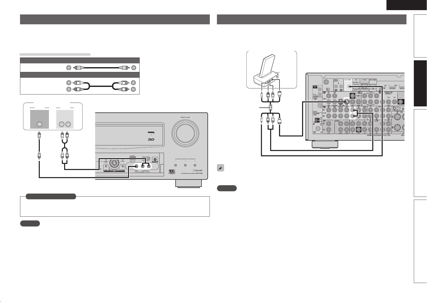
Connecting a control dock for iPod ············································· 21
Connecting an iPod or USB memory device to the USB port ····· 22
Connecting an antenna ······························································· 23
Connecting a record player ·························································24
Connecting a CD player ······························································24
Component equipped with a DENON LINK connector ···············25
Component with Multi-channel Output connectors ···················25
Connecting a external power amplifier ·······································25
Connecting to a home network (LAN) ········································26
Connecting an external control device ········································ 27
Playback (Basic operation) ·························································28
Important information ·································································28
Playing a Blu-ray Disc player/DVD player ····································29
Playing a CD player ·····································································30
Playing an iPod
®
·········································································30
Tuning in radio stations ······························································· 33
Playing a network audio ······························································ 37
Playing a USB memory device ···················································· 48
Selecting a listening mode (Surround Mode) ·························· 50
Standard playback ······································································· 50
DENON original surround playback ············································· 52
Stereo playback ··········································································52
Direct playback ···········································································52
Pure direct playback····································································52
Advanced version ·······························································53
Speaker installation/connection (Advanced connection) ·······54
Install ·························································································· 54
Connect ······················································································ 56
Set up speakers ·········································································· 63
Playback (Advanced operation) ·················································65
Convenient functions ·································································· 65
Playback in ZONE2/ZONE3 (Separate room) ·························· 72
Audio output ···············································································72
Video output ··············································································· 72
Playback ······················································································ 73
Menu Operation··········································································73
Quick select function ··································································74
Sleep timer function ···································································74
How to make detailed settings ··················································75
Menu map ·················································································· 75
Examples of menu screen displays ············································76
Examples of menu and front display ··········································77
Inputting characters ···································································78
SOURCE SELECT ·······································································80
AUDIO/VIDEO ADJUST ······························································86
MANUAL SETUP ········································································93
INFORMATION ········································································· 107
Operating the connected devices by remote control unit ···· 108
Operating the main remote control unit ···································108
Operating the sub remote control unit ·····································115
Information ···········································································119
Part names and functions·························································120
Front panel ················································································ 120
Display ······················································································121
Rear panel ················································································· 122
Remote control unit ·································································· 123
Other information ·····································································125
Trademark information ······························································125
Surround ···················································································126
Relationship between video signals and monitor output ··········131
Explanation of terms ································································· 132
Troubleshooting ········································································135
Resetting the microprocessor ··················································138
Specifications ············································································139
Getting started ··············································································1
Accessories ··················································································2
About this manual ········································································· 2
Features ························································································ 2
Cautions on handling ····································································3
1.AVRA100E3_ENG_1st_0824.indd 1 2010/08/26 17:47:07
2
ENGLISH
Features
Fully Discrete, identical quality and power for all
9 channels (170 W x 9ch)
The unit is equipped with a power amplifi er that reproduces high-
fi delity sound in surround mode with equal quality and power for all
channels, true to the original sound.
The power amplifi er circuit adopts a discrete-circuit confi guration
that achieves high-quality surround sound reproduction.
Supports HDMI 1.4a with 3D, ARC, Deep Color,
x.v.Color , Auto Lipsync and HDMI control function
This unit can output 3D video signals input from a Blu-ray Disc
player to a TV that supports a 3D system. This unit also supports
the ARC (Audio Return Channel) function, which reproduces TV
sound with this unit via an HDMI cable used for connecting the
unit and a TV
z1
.
z1 The TV should support the ARC function.
Internet radio, music and photo streaming via
network
z2
This unit can playback audio fi les and still images such as
photographs that are stored on your computer via a network. You
can also listen to internet radio and a whole host of other online
music
z3
that uses network technology.
z2 An internet connection is required.
z3 You may be required to sign a service agreement with the
companies that provide particular services.
7-HDMI inputs and 2-outputs
The unit is equipped with 7 HDMI input connectors for connecting
devices with HDMI connectors, such as a Blu-ray Disc player,
game machine, HD video camera, etc.
Dolby Volume
Dolby Volume measures, analyzes, and maintains volume levels
based on how people perceive sound. It examines a variety of
audio parameters to maintain consistent playback levels whether
switching between channels or between multiple source inputs.
A sophisticated combination of spectral- and time-based loudness
analysis enables it to quickly and properly correct level differences
without creating compression artifacts or undesirable pumping in
the audio signal.
DENON LINK 4th support
When you connect this unit to a Denon Blu-ray disc player that
has DENON LINK 4th support, you can enjoy HD audio of the
highest quality. The master clock that operates the D/A converter
of this unit is transmitted to the Blu-ray disc player, enabling the
integrated circuitry to be operated while sharing the same clock
in order to achieve digital audio transmission with negligible jitter.
Sound localization becomes clearer and a greater sense of space is
produced in the sound images.
High defi nition audio support
The unit is equipped with a decoder which supports high-quality
digital audio format for Blu-ray Disc players such as Dolby TrueHD,
DTS-HD Master Audio, etc.
Audyssey MultEQ
®
XT 32
Audyssey MultEQ corrects both time and frequency response
problems in the listening area so that every listener can enjoy
music and movie with the optimum sounds. It performs a fully
automated surround system setup. The unit is equipped Audyssey
MultEQ XT 32 that can correct much higher details, particularly
in the bass range of the speakers. The high resolution correction
reproduces much clearer surround sound.
Discrete subwoofers and Audyssey multiple
subwoofer calibration
The unit has two subwoofer output capability and can adjust the
level and delay for each subwoofer individually. Audyssey multiple
subwoofer calibration optimizes the level, delay, and frequency
response blending of two subwoofers. It eliminates the phase
cancellations between two subwoofers. The optimized sound
reporoduces more powerful sound.
Audyssey DSX™
This unit is equipped with Audyssey DSX processor. By connecting
front height speakers to this unit and playing back through Audyssey
DSX, you can experience a more powerful playback expression in
the height audio range. By connecting front wide speakers, you
can experience a more powerful playback expression in the wide
audio range.
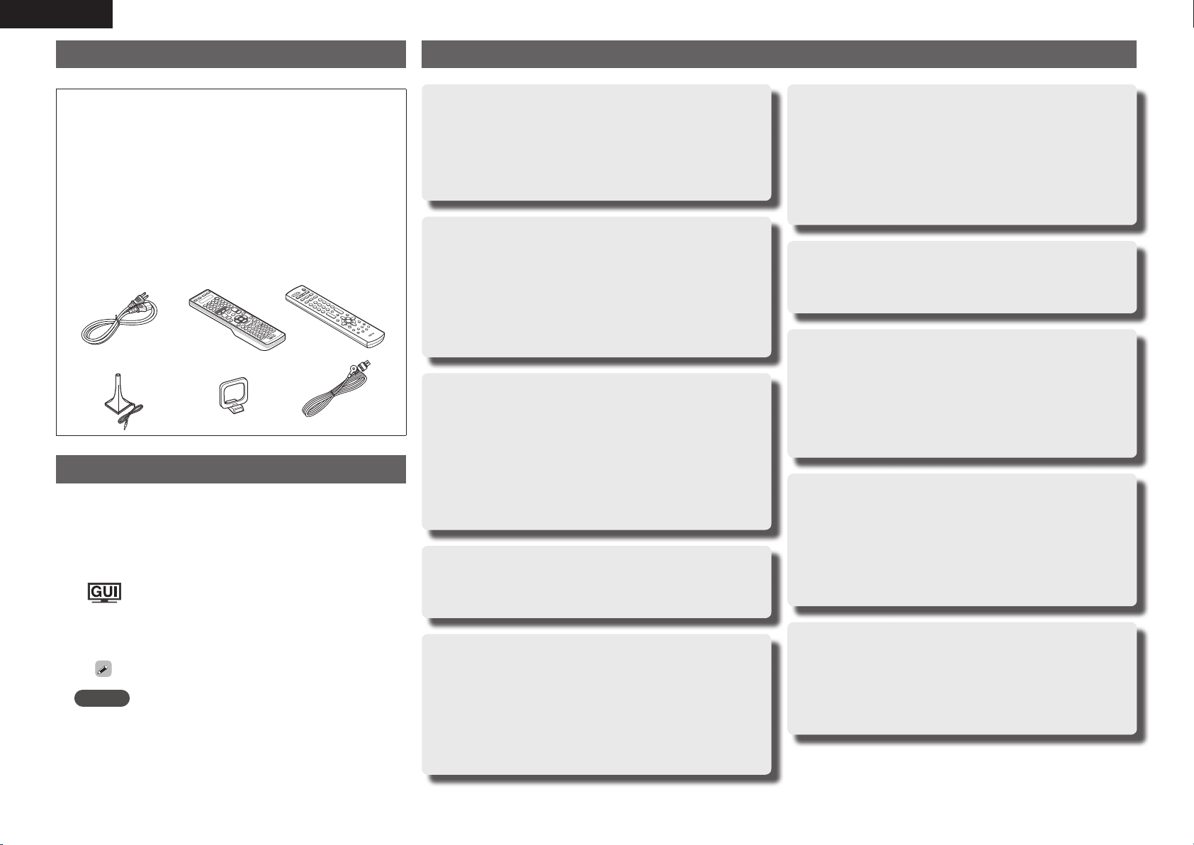
Accessories
Check that the following parts are supplied with the product.
q Owner’s manual ...................................................................... 1
w Warranty (for North America model only) ................................ 1
e Service network list ................................................................. 1
r Power cord (Cord length: Approx. 6.2 ft / 1.9 m) .................... 1
t Main remote control unit (RC-1145) ........................................ 1
y R6/AA batteries (for RC-1145) ................................................. 2
u Sub remote control unit (RC-1148) .......................................... 1
i R03/AAA batteries (for RC-1148) ............................................. 2
o Setup microphone
(DM-A409, Cord length: Approx. 19.7 ft / 6.0 m) .................... 1
Q0 AM loop antenna (for HD Radio broadcasts) ........................... 1
Q1 FM indoor antenna (for HD Radio broadcasts) ........................ 1
tr
Q0 Q1
u
o
About this manual
n Operation buttons
The operations described in this manual are based mainly on
remote control operation.
n Symbols
Items for which this mark is indicated at the title can
be operated from the GUI menu.
We recommend performing such operations from
the GUI menu.
v
This symbol indicates a reference page on which
related information is described.
This symbol indicates a supplementary information
and tips for operations.
NOTE
This symbol indicates a supplementary information
and tips for operations.
n Illustrations
Note that the illustrations in these instructions are for explanation
purposes and may differ from the actual unit.
1.AVRA100E3_ENG_1st_0824.indd 2 2010/08/26 17:47:10

3
Basic versionSimple version Advanced version Information
ENGLISH
Cautions on handling
• Before turning the power switch on
Check once again that all connections are correct and that there are
no problems with the connection cables.
• Power is supplied to some of the circuitry even when the unit is
set to the standby mode. When going on vacation or leaving home
for long periods of time, be sure to unplug the power cord from the
power outlet.
• About condensation
If there is a major difference in temperature between the inside of
the unit and the surroundings, condensation (dew) may form on
the operating parts inside the unit, causing the unit not to operate
properly.
If this happens, let the unit sit for an hour or two with the power
turned off and wait until there is little difference in temperature
before using the unit.
• Cautions on using mobile phones
Using a mobile phone near this unit may result in noise. If that
occurs, move the mobile phone away from this unit when it is in use.
• Moving the unit
Turn off the power and unplug the power cord from the power
outlet. Next, disconnect the connection cables to other system units
before moving the unit.
• About Care
• Wipe the cabinet and control panel clean with a soft cloth.
• Follow the instructions when using a chemical cleaner.
• Benzene, paint thinner or other organic solvents as well as
insecticide may cause material changes and discoloration if brought
into contact with the unit, and should therefore not be used.
Features
Easy to use, Graphical User Interface
This unit is equipped with an easy to see “Graphical User
Interface” that uses menu displays and levels. The use of level
displays increases operability of the this unit.
All sources are up-scaled to 1080p
The unit is provided with an HDMI video up-scaling function that
converts an analog video signal input to the unit to a 1080p (HD
resolution) signal and supplies it to a TV via the HDMI connector.
This enables the unit and a TV connected with a single HDMI cable
and any video source to be reproduced precisely with HD level of
quality.
Direct play for iPod
®
and iPhone
®
via USB
Music data from an iPod can be played back if you connect the
USB cable supplied with the iPod via the USB port of this unit, and
also an iPod can be controlled with the remote control unit for this
unit.
When an iPod is connected, merely pressing iPod PLAY on the
main unit or remote control unit starts playback of music from the
iPod.
Simultaneous playback on two HDMI channels
This unit is equipped with two HDMI MONITOR outputs. You can
connect one output to a projector and the other output to a TV for
simultaneous signal outputs.
1.AVRA100E3_ENG_1st_0824.indd 3 2010/08/26 17:47:11
Simple
version
4
ENGLISH
Simple version (Simple setup guide)
Here, we explain the entire setup procedure, from unboxing the unit to using it in a home theater.
The “Simple version” section provides the speaker installation, connection, and setup methods for the 7.1-channel system with surround
back speakers. For the installing, connecting, and setup methods of speakers other than the 7.1-channel system (with surround back
speakers), see page 54.
n Before connecting the unit, turn off the power to all devices.
n For operation of the connected devices, refer to the user manuals for each device.
Play back
disc
(vpage13)
Enjoy Blu-ray Disc in
surround sound.
5
Set up
speakers
(vpage7)
Use the setup microphone
(DM-A409) included
with the product, for
automatic setup.
4
Finish
STEP 6
Store
STEP 5
Check
STEP 4
Calculation
STEP 3
Measurement
(2nd – 8th listening position)
STEP 2
Detection &
Measurement
(Main listening position)
STEP 1
Preparation
Set up speakers (Audyssey
®
Auto Setup)
Turn on
power
(vpage7)
3
Connect
(vpage5)
Connect 7.1-channel
speakers, a TV and
Blu-ray Disc player
equipped with an HDMI
connector.
2
Install
(vpage5)
Enjoy better audio, using
the correct install method.
1
1.AVRA100E3_ENG_1st_0824.indd 4 2010/08/26 17:47:11
5
Basic version Advanced version Information
ENGLISH
Simple version
Speakers
Carefully check the left (L) and right (R)
channels and + (red) and – (black) polarities
on the speakers being connected to the
this unit, and be sure to interconnect the
channels and polarities correctly.
Connecting the speaker cables
Peel off about 0.03 ft/10 mm of sheathing from
the tip of the speaker cable, then either twist the
core wire tightly or terminate it.
When using a banana plug
Tighten the speaker terminal fi rmly before
inserting the banana plug.
NOTE
• Connect so that the speaker cable core wires
do not protrude from the speaker terminal.
The protection circuit may be activated if the
core wires touch the rear panel or if the + and –
sides touch each other (vpage134 “Protection
Circuit”).
• Never touch the speaker terminals while the
power supply is connected. Doing so could
result in electric shock.
• Use speakers with the speaker impedances
shown below.
Speaker terminals
Speaker
impedance
FRONT
4 – 16 Ω
CENTER
SURROUND
SURR. BACK / AMP ASSIGN
F.HEIGHT / AMP ASSIGN
F.WIDE / AMP ASSIGN
Use speakers where one speaker has an
impedance of 4 to 16 Ω.
When using a speaker with impedance of 4 Ω or
6 Ω, make sure to set the “Speaker Impedance”
in the menu (vpage98) to “6 Ω/ohms” or “4 Ω/
ohms”.
Install
1 2 3 4 5
This unit can perform 2.0 to 11.2-channel surround playback.
This page provides the speaker installation procedure for the
7.1-channel playback using surround back speakers as an example.
FL FR
C
SBL SBR
SL
SR
SW
90 – 110˚
22 – 30˚
135 – 150˚
Listening
position
FL Front speaker (L) • Install the surround speakers in a position 2 to
3 ft (60 to 90 cm) higher than ear level.
Surround back
speaker
• Point slightly
downwards
Front
speaker
Surround
speaker
2 – 3 ft /
60 – 90 cm
GViewed from the sideH
FR Front speaker (R)
C Center speaker
SW Subwoofer
SL Surround speaker (L)
SR Surround speaker (R)
SBL Surround back speaker (L)
SBR Surround back speaker (R)
1
Connect
1 2 3 4 5
2
The “Simple version” section provides the speaker installation, connection, and setup methods for the 7.1-channel system with surround back speakers.
For the installing, connecting, and setup methods of speakers other than the 7.1-channel system (with surround back speakers), see page 54 .
1.AVRA100E3_ENG_1st_0824.indd 5 2010/08/26 17:47:12

6
ENGLISH
Blu-ray Disc player and TV
Use only an HDMI (High Defi nition Multimedia Interface) cable that bears the HDMI
logo (a genuine HDMI product). Using a cable without the HDMI logo (a non-genuine
HDMI product) may result in abnormal playback.
When outputting Deep Color or 1080p, etc., we recommend you use a “High Speed
HDMI cable” or a “High Speed HDMI cable with Ethernet”for enhanced high-quality
playback.
IN
HDMI
OUT
HDMI
To household power outlet
(AC 120 V, 60 Hz)
Power cord
(supplied)
HDMI cable
(sold separately)
HDMI cable
(sold separately)
Blu-ray Disc player
TV
If your TV does not support the ARC function
(vpage 16), make the audio connection
referring to “Connecting a TV” (vpage18).
TV sound can be played on this unit.
NOTE
• Do not plug in the power cord until all connections have been completed.
• Do not bundle power cords together with connection cables. Doing so can result in humming or noise.
Connect
FL FR
C
SL
SR
SW
SBL SBR
Speaker cables
(sold separately)
Audio cable
(sold separately)
Subwoofer with
built-in amplifi er
The “Simple version” section provides the speaker installation, connection, and setup methods for the 7.1-channel system with surround back speakers.
For the installing, connecting, and setup methods of speakers other than the 7.1-channel system (with surround back speakers), see page 54 .
1.AVRA100E3_ENG_1st_0824.indd 6 2010/08/26 17:47:15
7
Basic version Advanced version Information
ENGLISH
Simple version
The acoustic characteristics of the connected speakers and listening room are
measured and the optimum settings are made automatically. This is called
“Audyssey Auto Setup”.
To perform measurement, place the setup microphone in multiple locations all
around the listening area. For best results, we recommend you measure in six
or more positions, as shown in the illustration (up to eight positions).
• When performing Audyssey Auto Setup, MultEQ
®
XT 32/Dynamic EQ
®
/Dynamic
Volume
®
functions become active (vpage89, 90).
• To set up the speakers manually, use “Speaker Setup” (vpage93) on the menu.
NOTE
• Make the room as quiet as possible. Background noise can disrupt the room measurements. Close
windows, silence cell phones, televisions, radios, air conditioners, fl uorescent lights, home appliances,
light dimmers, or other devices as measurements may be affected by these sounds.
• Cell phones should be placed away from all audio electronics during the measurement process as Radio
Frequency Interference (RFI) may cause measurement disruptions (even if the cell phone is not in use).
• Do not unplug the setup microphone from the main unit until Audyssey Auto Setup is completed.
• Do not stand between the speakers and setup microphone or allow obstacles in the path while the
measurements are being made. This will cause inaccurate readings.
• Loud test sounds may be played during Audyssey Auto setup. This is part of
normal operation. If there is background noise in room, these test signals will
increase in volume.
• Operating
VOL df during the measurements will cancel the measurements.
• Measurement cannot be performed when headphones are connected.
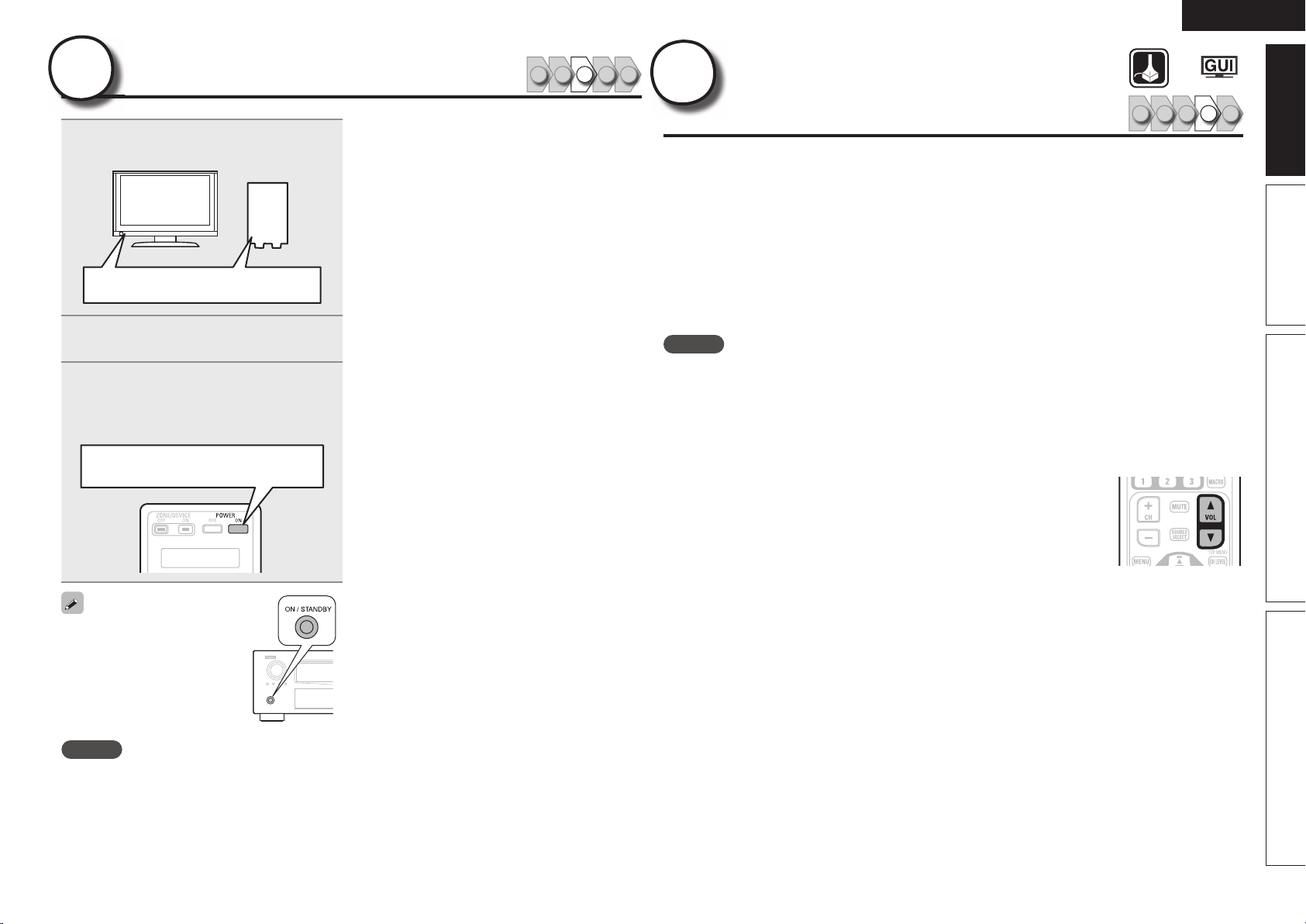
Turn on power
1 2 3 4 5
3
1
Turn on the TV and subwoofer
power.
Power on
2
Change the TV input to the input of
this unit.
3
Press POWER ON to turn on power to
the this unit.
The power indicator fl ashes green and the
power turns on.
Power on
You can also switch the power
to standby by pressing
ON/STANDBY on the main unit.
NOTE
Before you use the remote control unit for the fi rst
time, be sure to insert the batteries (vpage124
“Inserting the batteries”).
Set up speakers
(Audyssey
®
Auto Setup)
1 2 3 4 5
4
1.AVRA100E3_ENG_1st_0824.indd 7 2010/08/26 17:47:15
8
ENGLISH
About setup microphone placement
• Measurements are performed by placing the setup microphone
successively at multiple positions throughout the entire listening
area, as shown in GExample qH. For best results, we recommend
you measure in six or more positions, as shown in the illustration
(up to eight positions).
• Even if the listening environment is small as shown in GExample wH,
measuring at multiple points throughout the listening environment
results in more effective correction.
FL SW C FR
SR
SBL SBR
SL
*
M
FL SW C FR
SR
SBL SBR
SL
*
M
(
: Measuring positions)
GExample qH GExample wH
(
: Measuring positions)
FL Front speaker (L) SL Surround speaker (L)
FR Front speaker (R) SR Surround speaker (R)
C Center speaker SBL Surround back speaker (L)
SW Subwoofer SBR Surround back speaker (R)
About the main listening position (*M)
The main listening position is the position where listeners would
normally sit or where one would normally sit alone within the listening
environment. Before starting Audyssey Auto Setup, place the setup
microphone in the main listening position. Audyssey MultEQ
®
XT 32
uses the measurements from this position to calculate speaker
distance, level, polarity, and the optimum crossover value for the
subwoofer.
About multiple subwoofer calibration
Audyssey multiple subwoofer calibration optimizes the level, delay,
and frequency response blending of two subwoofers.
z To run Audyssey multiple subwoofer calibration you must select
“Measure (2 spkrs)” in “Set up “Channel Select”” (vpage64).
The “Simple version” section provides the speaker installation, connection, and setup methods for the 7.1-channel system with surround back speakers.
For the installing, connecting, and setup methods of speakers other than the 7.1-channel system (with surround back speakers), see page 54 .
Set up speakers (Audyssey
®
Auto Setup)
3
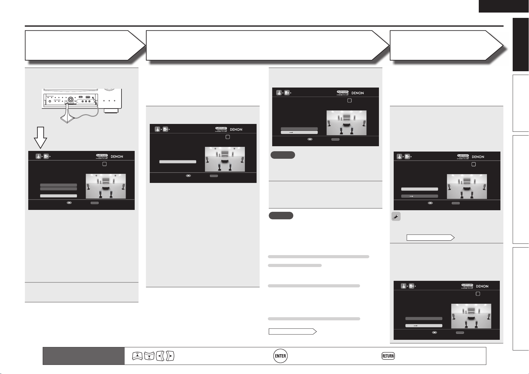
Set up the remote control unit
n Set up the zone mode
Press ZONE SELECT to switch the zone mode to
M
(MAIN ZONE).
The
M
indicator lights.
Press ZONE SELECT
n Set up the operation mode
Press AMP to set the remote control unit to AMP-
operation mode.
Press AMP
1
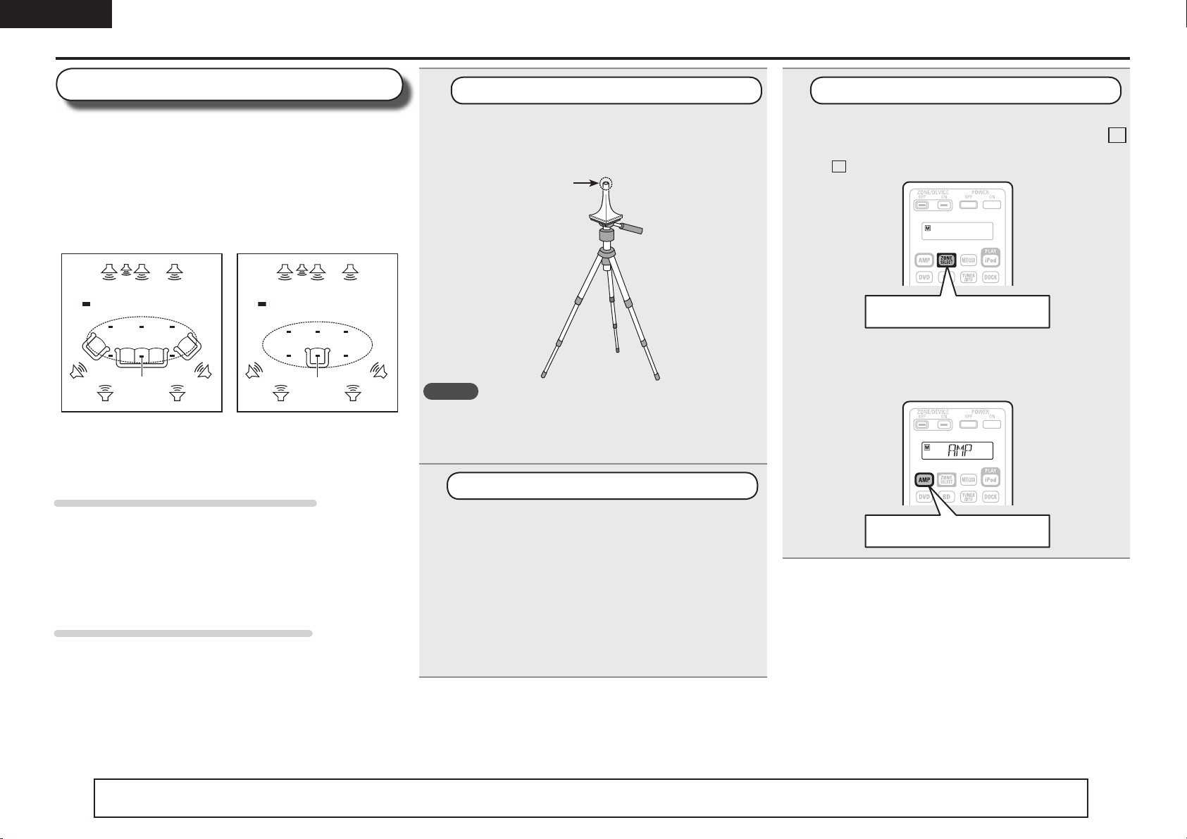
Prepare the setup microphone
Mount the setup microphone on a tripod or stand
and place it in the main listening position.
When placing the setup microphone, adjust the height of the
sound receptor to the level of the listener’s ear.
Sound receptor
Setup
microphone
NOTE
• Do not hold the setup microphone in your hand during
measurements.
• Avoid placing the setup microphone close to a seat back or wall as
sound refl ections may give inaccurate results.
2
Set up the subwoofer
If using a subwoofer capable of the following
adjustments, set up the subwoofer as shown below.
n When using a subwoofer with a direct mode
Set the direct mode to “On” and disable the volume adjustment
and crossover frequency setting.
n When using a subwoofer without a direct mode
Make the following settings:
• Volume : “12 o’clock position”
• Crossover frequency : “Maximum/Highest Frequency”
• Low pass fi lter : “Off”
• Standby mode : “Off”
1.AVRA100E3_ENG_1st_0824.indd 8 2010/08/26 17:47:16
9
Basic version Advanced version Information
ENGLISH
Simple version
Set up speakers (Audyssey
®
Auto Setup)
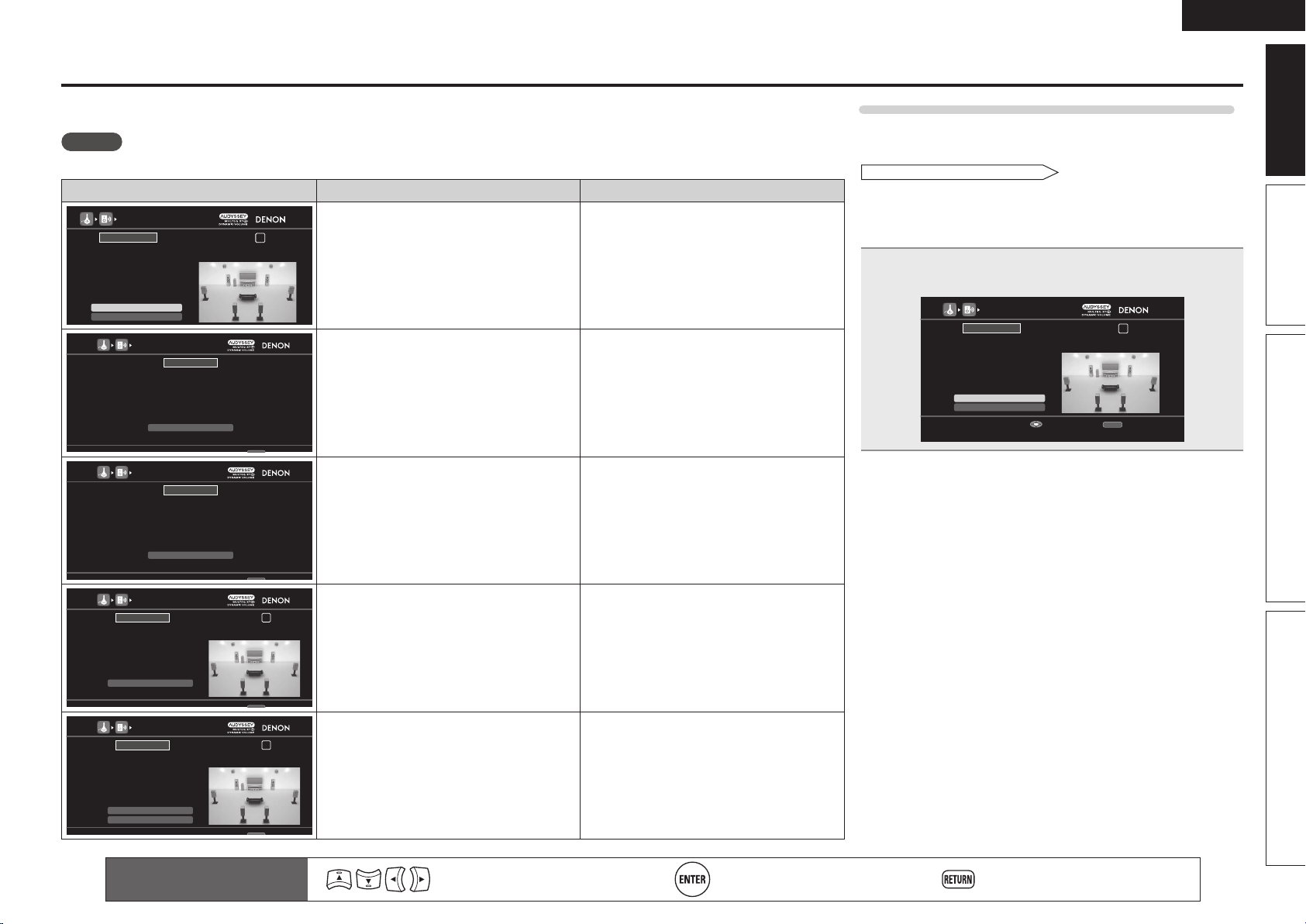
STEP 1
Preparation
Remote control operation
buttons
Move the cursor
(Up/Down/Left/Right)
Confi rm the setting Return to previous menu
STEP 2
Detection & Measurement
(Main listening position)
STEP 3
Measurement
(2nd – 8th listening position)
7
The detected speakers are displayed.
AUDYSSEY AUTO SETUP
1 2 3 4 5 6
RETURN
Next Measurement
Retry
STEP2 Speaker Detection Check
Front
Center
Subwoofer
Surround
Surround Back
Front Height
Yes
Yes
1spkr
Yes
2spkrs
No
Proceed to STEP 3 after checking speaker connection result
Enter Cancel
NOTE
If a connected speaker is not displayed, the
speaker may not be connected correctly. Check
the speaker connection.
8
Use ui to select “Next →
Measurement” and then press
ENTER.
• In STEP 3, you will perform measurements at
multiple positions (two to eight positions) other
than the main listening position.
• You can achieve a more effective correction of
distortion within the listening area by performing
measurements at multiple positions.
9
Move the setup microphone to
position 2, use ui to select
“Measure”, and then press ENTER.
The measurement of the second position
starts. Measurements can be made in up to
eight positions.
AUDYSSEY AUTO SETUP
1 2 3 4 5 6
RETURN
Next Calculation
Measure
STEP3 Measurement(2nd-8th)
Please place the microphone at ear
height at 2nd Iistening position.
Start measurement. Output large test tone during measuring
Enter Cancel
If you want to omit measurements from the next
position onward, select “Next → Calculation”.
(Go to
STEP4 Calculation
)
10
Repeat step 9, measuring positions 3
to 8.
When measurement of position 8 is
completed, a “Measurements fi nished.”
message is displayed.
AUDYSSEY AUTO SETUP
1 2 3 4 5 6
RETURN
Next Calculation
Proceed to STEP4 (Calculation)
Enter Cancel
Retry
STEP3 Measurement(2nd-8th)
Measurements finished.
NOTE
If “Caution” is displayed:
Go to “Error messages” (vpage 11), check
any related items, and perform the necessary
procedures.
When performing Audyssey Auto
Setup over again
Press ui to select “Retry”, and then press ENTER.
When measuring has stopped
Press RETURN, to the “Cancel auto setup?” prompt
is displayed.
Press o to select “Yes”, then press ENTER.
Setting up the speakers again
Repeat the operation from step 4 of
STEP1 Preparation
.
• In STEP 2, you will perform measurements at the
main listening position.
• This step automatically checks the speaker
confi guration and speaker size, and calculates the
channel level, distance, and crossover frequency.
It also corrects distortion in the listening area.
6
Select “Measure” and then press
ENTER.
AUDYSSEY AUTO SETUP
1 2 3 4 5 6
RETURN
Measure
STEP2 Detection & Measurement (main)
Please place the microphone at ear
height at main Iistening position.
Start measurement. Output large test tone during measuring
Enter Cancel
q Measure the subwoofer level
• To stop measuring, select “Cancel” and then
press ENTER.
• When “Subwoofer” is set to “Skip” with
“Channel Select”, this measurement is not
taken, and the process proceeds to “w
Measure each speaker”.
w Measure each speaker
• Once the measurements in step q are
complete, the measurements in step w start
automatically.
• The measuring channel changes depending
on the setting of “Set up “Amp Assign””
(vpage63) and “Set up “Channel Select””
(vpage64).
• Measurement requires several minutes.
4
Connect the setup microphone to the
SETUP MIC jack of this unit.
AUDYSSEY AUTO SETUP
1 2 3 4 5 6
Amp Assign
RETURN
Auto Setup Start
Channel Select
STEP1 Preparation
Connect the speakers and place them according
to the recommendations in the manual,
Set the following items
If necessary.
Start Auto Setup
Enter Cancel
When the setup microphone is
connected, the following screen is
displayed.
This screen provides the method for setting
up 7.1-channel playback using surround back
speakers. For the method of setting up speakers
other than the 7.1-channel system, select “Amp
Assign” and perform step 3 and 7 of “Set up
“Amp Assign”” (vpage63).
If unused channels are set with “Channel Select”,
measuring time can be shortened. Also, set
“Channel Select” to measure two subwoofers.
For setting, perform steps 9 to 14 of “Set up
“Channel Select”” (vpage64).
5
Use ui to select “Auto Setup Start”
and then press ENTER.
1.AVRA100E3_ENG_1st_0824.indd 9 2010/08/26 17:47:17
10
ENGLISH
11
On the
STEP3
screen, use ui
to select “Next → Calculation”, and
then press ENTER.
Measuring results are analyzed, and the
frequency response of each speaker in the
listening room is determined.
AUDYSSEY AUTO SETUP
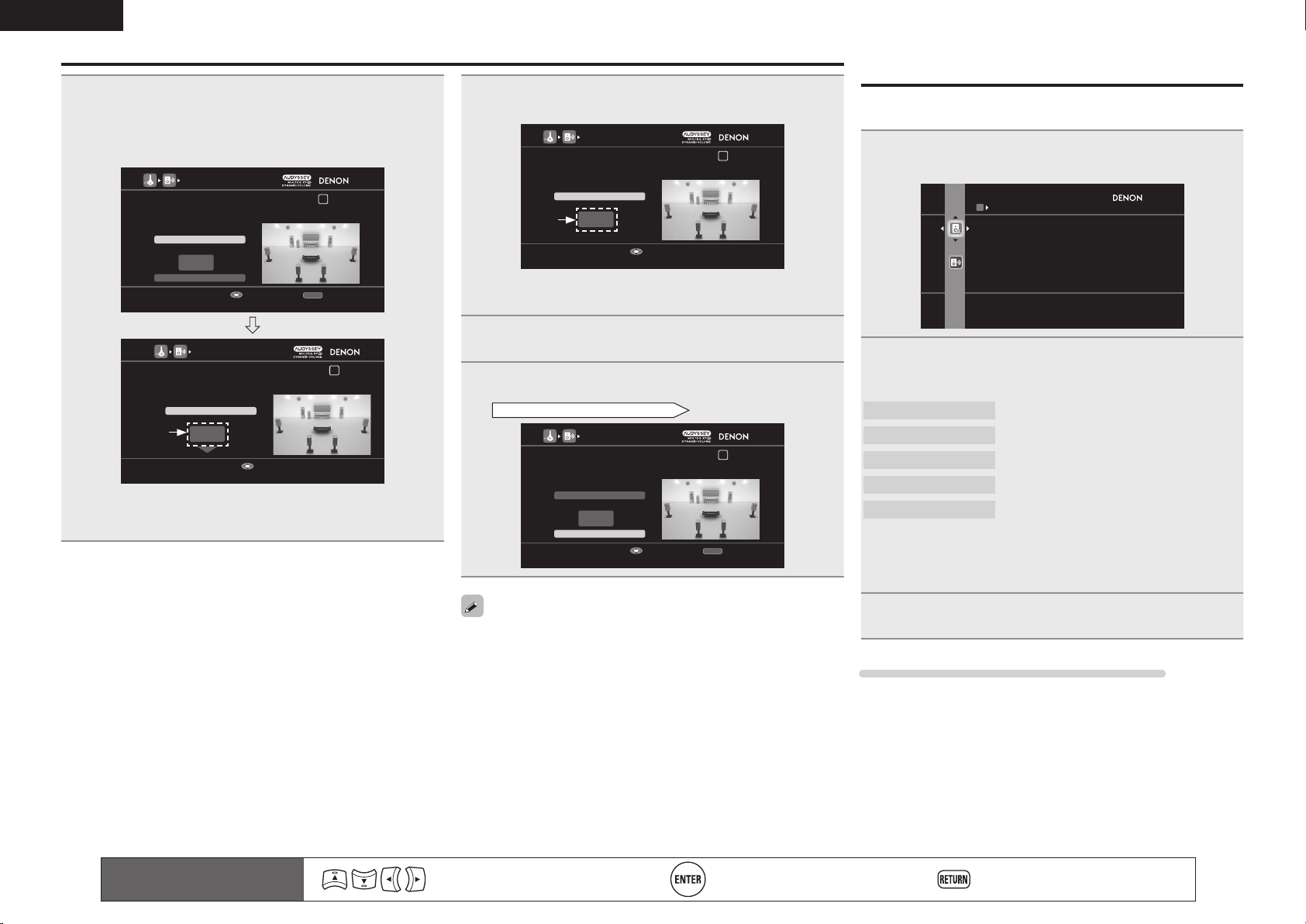
1 2 3 4 5 6
STEP4 Calculation
Now calculating...Please wait.
27%
• Analysis takes several minutes to complete. The
time required for this analysis depends on the
number of speakers connected.
The more connected speakers there are, the
longer it takes to perform analysis.
Set up speakers (Audyssey
®
Auto Setup)
STEP 4
Calculation
STEP 5
Check
12
Use ui to select the item you want
to check, and then press ENTER.
AUDYSSEY AUTO SETUP
1 2 3 4 5 6
RETURN
Next Store
Select item to check
Enter Cancel
Crossover Check
Ch.Level Check
Distance Check
Spkr Config Check
STEP5 Check
Check processing results.
To proceed,press “Next”.
• Subwoofers may measure a greater reported
distance than the actual distance due to added
electrical delay common in subwoofers.
• If you want to check another item, press
RETURN.
13
Use ui to select “Next → Store”
and then press ENTER.
14
Select “Store” and then press ENTER.
Save the measurement results.
AUDYSSEY AUTO SETUP
1 2 3 4 5 6
STEP6 Store
Now storing... Please wait.
78%
AUDYSSEY AUTO SETUP
1 2 3 4 5 6
RETURN
Apply and store measurement result
Enter Cancel
Store
STEP6 Store
Press “Store” to store calculation results.
• Saving the results requires about 20 seconds.
• If the measuring results are not to be saved,
press RETURN. A message “Cancel auto
setup?” will be displayed. Press o then select
“Yes”. All the measured Audyssey Auto Setup
data will be erased.
NOTE
During saving of measurement results, be sure
not to turn off the power.
Remote control operation
buttons
Move the cursor
(Up/Down/Left/Right)
Confi rm the setting Return to previous menu
NOTE
• If the result differs from the actual connection
status, or if “Caution!” is displayed, see “Error
messages” (vpage11). Then carry out Audyssey
Auto Setup again.
• If the result still differs from the actual connection
status after remeasurement or the error message
still appears, it is possible that the speakers
are not connected properly. Turn this unit off,
check the speaker connections and repeat the
measurement process from the beginning.
• If you change speaker positions or orientation,
perform Audyssey Auto Setup again to fi nd the
optimal equalizer settings.
STEP 6
Store
Finish
15
Unplug the setup microphone from
the unit’s SETUP MIC jack.
16
Set Dynamic Volume
®
.
AUDYSSEY AUTO SETUP
1 2 3 4 5 6
No
Yes
Turn Dynamic Volume on and exit Auto Setup
Exit
Finish
Storing complete.
Auto Setup is now finished.
Please unplug microphone.
Turn on Dynamic Volume?
• For details of Dynamic Volume settings, see
page 90.
n When turning Dynamic Volume on
Use u to select “Yes“, and then press ENTER.
• The unit automatically enters “Evening” mode.
n When turning Dynamic Volume off
Use i to select “No“, and then press ENTER.
NOTE
• After performing Audyssey Auto Setup, do not
change the speaker connections or subwoofer
volume. In event of a change, perform Audyssey
Auto Setup again.
• After performing Audyssey Auto Setup with two
subwoofers, do not change the channel distances
and levels of both subwoofers.
1.AVRA100E3_ENG_1st_0824.indd 10 2010/08/26 17:47:17
11
Basic version Advanced version Information
ENGLISH
Simple version
Error messages
An error message is displayed if Audyssey
®
Auto Setup could not be completed due to speaker placement, the measurement environment, etc.
If this happens, check the relevant items, be sure to take the necessary measures, then perform Audyssey Auto Setup over again.
NOTE
Be sure to turn off the power before checking speaker connections.
Examples Error details Measures
AUDYSSEY AUTO SETUP
1 2 3 4 5 6
RETURN
The subwoofer’s level is too high or low. Please select “SW
Level Matching” and adjust the level of your subwoofer unit.
If you do not want to use the
subwoofer, select “Skip”.
Proceed to subwoofer volume adjustment item
Enter Cancel
Skip
Caution!
SW Level Matching
• Correct measurement is not possible due to
inappropriate subwoofer volume.
• When using a subwoofer with built-in
amplifi er (active type), use “SW Level
Matching” to adjust the subwoofer volume
(vpage11 “Subwoofer level error message
and how to adjust”).
• When using a subwoofer without a built-in
amplifi er, select “Skip”, and then press
ENTER.
AUDYSSEY AUTO SETUP
RETURN
Check cause of problem!
Cancel
No microphone or speaker
Retry
Caution!
• The connected setup microphone is broken,
or a device other than the supplied setup
microphone is connected.
• Not all speakers could be detected.
• The front L speaker was not properly
detected.
• Connect the included setup microphone to
the SETUP MIC jack of this unit.
• Check the speaker connections.
AUDYSSEY AUTO SETUP
RETURN
Check cause of problem!
Cancel
Ambient noise is too high
or Level is too low
Retry
Caution!
• There is too much noise in the room for
accurate measurements to be made.
• Speaker or subwoofer sound is too low for
accurate measurements to be made.
• Either turn off any device generating noise
or move it away.
• Perform again when the surroundings are
quieter.
• Check the speaker installation and the
direction in which the speakers are facing.
• Adjust the subwoofer’s volume.
AUDYSSEY AUTO SETUP
1 2 3 4 5 6
RETURN
Front R None
Check cause of problem!
Cancel
Caution!
Retry
• The displayed speaker could not be detected. • Check the connections of the displayed
speaker.
AUDYSSEY AUTO SETUP
1 2 3 4 5 6
RETURN
Front L Phase
Check cause of problem!
Cancel
Caution!
Retry
Skip
• The displayed is connected with the
polarities reversed.
• Check the polarities of the displayed
speaker.
• For some speakers, this error message may
be displayed even if the speaker is properly
connected. If you are sure the connection is
correct, press ui to select “Skip”, then
press ENTER.
Remote control operation
buttons
Move the cursor
(Up/Down/Left/Right)
Confi rm the setting Return to previous menu
Subwoofer level error message and how to adjust
The optimal level of each subwoofer channel for Audyssey
Auto Setup measurement is 75 dB. During subwoofer level
measurement (“Set up speakers (Audyssey
®
Auto Setup),
STEP2 Detection & Measurement
” (vpage9), 6 – q), an error
message is displayed when one level of subwoofers is outside the
72 – 78 dB range. When using a subwoofer with built-in amplifi er
(active type), adjust the subwoofer volume so that the subwoofer
level is within the 72 to 78 dB range.
1
Select “SW Level Matching” and then press ENTER.
AUDYSSEY AUTO SETUP
1 2 3 4 5 6
RETURN
The subwoofer’s level is too high or low. Please select “SW
Level Matching” and adjust the level of your subwoofer unit.
If you do not want to use the
subwoofer, select “Skip”.
Proceed to subwoofer volume adjustment item
Enter Cancel
Skip
Caution!
SW Level Matching
1.AVRA100E3_ENG_1st_0824.indd 11 2010/08/26 17:47:18
12
ENGLISH
Parameter Check
This function enables you to check the measurement results and
equalizer characteristics after Audyssey Auto Setup.
1
Use ui to select “Parameter Check” and then
press ENTER or p.
PARAMETER CHECK
Spkr Config Check
Distance Check
Ch. Level Check
Crossover Check
EQ Check
Restore
Check auto setup measurement results
2
Use ui to select the item you want to check, then
press ENTER or p.
Measurement results for each speaker are displayed.
Speaker Confi g Check
Distance Check
Ch. Level Check
Crossover Check
EQ Check
Check the speaker confi guration.
Check the distance.
Check the channel level.
Check the crossover frequency.
Check the equalizer.
• If “EQ Check” is selected, press ui to select equalizing curve
(“Audyssey” or “Audyssey Flat”) to be checked, and then press
ENTER or p.
Use ui to switch the display between the different speakers.
3
Press RETURN.
The confi rmation screen reappears. Repeat steps 2.
Retrieving Audyssey Auto Setup settings
If you set “Restore” to “Yes”, you can return to Audyssey Auto Setup
measurement result (value calculated at the start by MultEQ
®
XT 32)
even when you have changed each setting manually.
Remote control operation
buttons
Move the cursor
(Up/Down/Left/Right)
Confi rm the setting Return to previous menu
Error messages
2
Select “SW Test Start” and then press ENTER.
Subwoofer level measurement begins.
During measuring, a “Testing …” message is displayed.
The measured level appears on the level indicator after about
3 to 5 seconds.
AUDYSSEY AUTO SETUP
1 2 3 4 5 6
RETURN
Next
dB
SW Test Start
Subwoofer Level Matching
Please place the microphone at ear height at main
listening position, then push ENTER.
Start measurement Output test tone from subwoofer
Enter Cancel
AUDYSSEY AUTO SETUP
1 2 3 4 5 6
79.1dB
Stop
Subwoofer Level Matching
Please adjust the level of your active subwoofer unit
so that the level Indicates approx. 75dB
Change from red to blue when level matches
Enter
Red
• If the measured level is outside the 72 to 78 dB range, the level
indicator is red.
• When measuring stops, press
ENTER.
3
Adjust the volume control on your subwoofer so that
the measured level is within the 72 to 78 dB range.
AUDYSSEY AUTO SETUP
1 2 3 4 5 6
73.9dB
Stop
Subwoofer Level Matching
Please adjust the level of your active subwoofer unit
so that the level Indicates approx. 75dB
Change from red to blue when level matches
Enter
Blue
• If the measured level is within the 72 to 78 dB range, the level
indicator is blue.
4
When the measured level is within the 72 to 78 dB
range, press ENTER.
5
Select “Next” and then press ENTER.
Proceed to “Set up speakers (Audyssey
®
Auto Setup),
STEP2 Detection & Measurement
” (vpage9), 6 – w.
AUDYSSEY AUTO SETUP
1 2 3 4 5 6
RETURN
SW Test Start
dB
Next
Subwoofer Level Matching
After adjustment, push “Next”.
Proceed to next measurement
Enter Cancel
When you use two subwoofers, adjust each subwoofer so that the
volume levels of Subwoofer 1 and Subwoofer 2 are appropriate for
your needs.
1.AVRA100E3_ENG_1st_0824.indd 12 2010/08/26 17:47:18
13
Basic version Advanced version Information
ENGLISH
Simple version
Play back disc
1 2 3 4 5
5
1
Press BD to switch an input source
for a player used for playback.
2
Play the component connected to
this unit.
Make the necessary settings on the
player (language setting, subtitles
setting, etc.) beforehand.
3
Adjust the sound volume.
VOL d ........................................... Volume up
VOL f ...................................... Volume down
MUTE .................................................. Muting
4
Set the listening mode.
Set the listening mode according to the playback contents
(cinema, music, etc.) or according to your liking (vpage 50
“Selecting a listening mode (Surround Mode)”).
When power is switched to standby
Press POWER OFF.
GPower indicator status in standby modeH
• Normal standby : Off
• When “HDMI Control” – “Control” is set to
“ON” : Red
• When “Network Standby” is set to “ON” :
Red
You can also switch the power to standby by
pressing ON/STANDBY on the main unit.
NOTE
During power standby, a minimal amount of power is consumed. To
totally cut off the power, remove the power cord from the power
outlet.
1.AVRA100E3_ENG_1st_0824.indd 13 2010/08/26 17:47:19
Basic
version
14
ENGLISH
F Connections vpage15
F Playback (Basic operation) vpage28
F Selecting a listening mode (Surround Mode) vpage50
n Refer to the pages indicated below for information on connecting and playing back the various
media and external devices.
Audio and Video
PlaybackConnection
TV
vpage17, 18
–
Blu-ray Disc player
vpage17, 18 vpage29
DVD player
vpage17, 19 vpage29
Set-top box (Satellite tuner or cable TV)
vpage17, 19
–
Digital video recorder
vpage17, 20
–
Game console
vpage17
–
Digital camcorder
vpage21
–
Control dock for iPod
vpage21 vpage30
Audio
PlaybackConnection
iPod
®
vpage22 vpage32
USB memory device
vpage22 vpage48
SIRIUS satellite radio
vpage23 vpage33
HD Radio receiver
vpage23 vpage35
Record player
vpage24
–
CD player
vpage24 vpage30
Network
PlaybackConnection
Network
vpage26 vpage37
For speaker connections, see page 5.
Basic version
Here, we explain the connections and basic operation methods for this unit.
1.AVRA100E3_ENG_1st_0824.indd 14 2010/08/26 17:47:19
15
Simple version Advanced version Information
ENGLISH
Basic version
Important information
• Make connections as follows before using this unit. Select an appropriate connection type
according to the components to be connected.
• You may need to make some settings on this unit depending on the connection method. Refer to
each description for more information.
• Select the cables (sold separately) according to the components being connected.
NOTE
• Do not plug in the power cord until all connections have been completed.
• When making connections, also refer to the operating instructions of the other components being
connected.
• Be sure to connect the left and right channels properly (left with left, right with right).
• Do not bundle power cords together with connection cables. Doing so can result in noise.
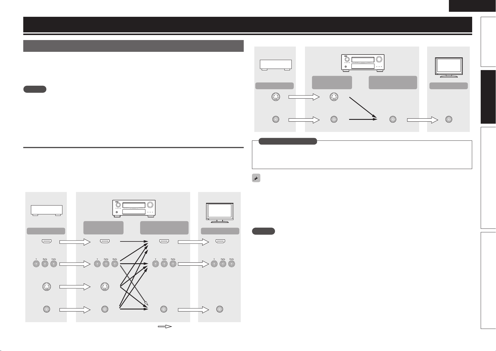
Converting input video signals for output
(Video conversion function)
This unit is equipped with four types of video input connectors (HDMI, Component video, S-Video and
video) and three types of video output connectors (HDMI, Component video and video).
Use the connectors corresponding to the components to be connected.
This function automatically converts various formats of video signals input to this unit into the formats used
to output the video signals from this unit to a monitor.
GFlow of video signals for MAIN ZONEH
HDMI connector
Component video
connectors
S-Video connector
Video connector
Monitor
HDMI connector
Component video
connectors
Component video
connectors
Component video
connectors
S-Video connector
Video connector
HDMI
connector
Video connector
HDMI connector
Video connector
Video device
This unit
Output
Input
(IN)
Output
(MONITOR OUT)
Input
: when 480i/576i signals are input
Connections
GFlow of video signals for ZONE2H
S-Video connector
Video connector
Monitor
S-Video connector
Video connector Video connector Video connector
Video device
This unit
Output
Input
(IN)
Output
(MONITOR OUT)
Input
• Set when not using the video conversion function.
“Video Convert” (vpage83)
• Set when changing the resolution of the video signal.
“Resolution” (vpage84)
in Set as Necessary
• The video conversion function supports the NTSC, PAL, SECAM, NTSC 4.43, PAL-N, PAL-M and PAL-60
formats.
• The resolution of the video signal input to this unit’s HDMI connector is the one set at “Resolution”
(vpage84). (1080p HDMI signals and 1080p component signals are output at 1080p, regardless of the
setting.)
• Resolutions of HDMI-compatible TVs can be checked at “HDMI Information” – “Monitor 1” or “Monitor
2” (vpage107).
NOTE
• HDMI signals cannot be converted into analog signals.
• When a non-standard video signal from a game machine or some other source is input, the video
conversion function might not operate.
• 480p/576p/1080i/720p/1080p component video input signals cannot be converted into Video format.
1.AVRA100E3_ENG_1st_0824.indd 15 2010/08/26 17:47:19
16
ENGLISH
Important information
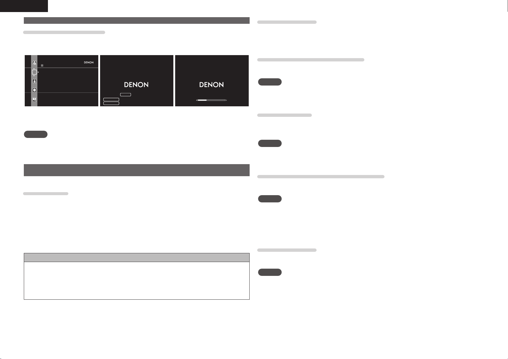
Examples of screen display
• Menu screen • Status display screen
When the input source is
switched
When the volume is adjusted
AUDIO/VIDEO ADJUST
Audio Adjust
Picture Adjust
Adjust various audio and video
parameters
AUTO
STEREO
BD
SURROUND
SOURCE
-52.0dB
Status display: The operating status appears briefl y on the screen
when the input source is switched or the volume is
changed.
NOTE
• If you operate the menu while playing back 3D video content, the playback video is replaced by the menu
screen. The playback video is not displayed behind the menu screen.
• This unit does not show the status display while playing back 3D video content.
Connecting an HDMI-compatible device
You can connect up to seven HDMI-compatible devices to the unit.
HDMI function
This unit supports the following HDMI functions:
• 3D
• Deep Color (vpage132)
• Auto Lip Sync (vpage98, 132)
• x.v.Color, sYCC601 color, Adobe RGB color, Adobe YCC601 color (vpage132, 134)
• High defi nition digital audio format
• ARC (Audio Return Channel)
• Content Type
• CEC (HDMI control)
Copyright protection system
In order to play back digital video and audio such as BD-Video or DVD-Video via HDMI connection, both
this unit and TV or the player need to support the copyright protection system known as HDCP (High-
bandwidth Digital Content Protection System). HDCP is copyright protection technology comprised of
data encryption and authentication of the connected AV device. This unit supports HDCP.
• If a device that does not support HDCP is connected, video and audio are not output correctly. Read
the owner’s manual of your television or player for more information.
About HDMI cables
• When a device supporting Deep Color signal transfer is connected, use a cable compatible “High Speed
HDMI cable” or “High Speed HDMI cable with Ethernet”.
• When the ARC function is used, connect a device with a ”Standard HDMI cable with Ethernet” or “High
Speed HDMI cable with Ethernet” for HDMI 1.4a.
HDMI control function (vpage65)
This function allows you to operate external devices from the receiver and operate the receiver from
external devices.
NOTE
• The HDMI control function may not work depending on the device it is connected to and its settings.
• You cannot operate a TV or Blu-ray Disc player/DVD player that is not compatible with the HDMI control
function.
About 3D function
This unit supports input and output of 3D (3 dimensional) video signals of the HDMI 1.4a standards.
To play back 3D video, you need a TV and player that provide support for HDMI1.4a standard 3D function
and a pair of 3D glasses.
NOTE
• If you operate the menu while playing back 3D video content, the playback video is replaced by the menu
screen. The playback video is not displayed behind the menu screen.
• This unit does not show the status display while playing back 3D video content.
About ARC (Audio Return Channel) function
The Audio Return Channel in HDMI 1.4a enables a TV, via a single HDMI cable, to send audio data “upstream”
to this unit.
NOTE
• To enable the ARC function, set “HDMI Control” – “Control” to “ON” (vpage99).
• The ARC function cannot use the HDMI MONITOR 1 and HDMI MONITOR 2 terminals simultaneously.
Perform the “HDMI Control” – “Control Monitor” setting in accordance with a TV that supports the ARC
function and HDMI MONITOR terminal in this unit.
• When connecting a TV that does not support the ARC function, a separate connection using an audio
cable is required. In this case, refer to “Connecting a TV” (vpage18) for the connection method.
About Content Type
The HDMI specifi cation version 1.4a enables simple, automated picture setting selection with no user
intervention.
NOTE
To enable the Content Type, set “Video Mode” to “Auto” (vpage83).
1.AVRA100E3_ENG_1st_0824.indd 16 2010/08/26 17:47:19
17
Simple version Advanced version Information
ENGLISH
Basic version
• When this unit is connected to other devices with HDMI cables, connect this unit and TV also with an
HDMI cable.
• When connecting a device that supports Deep Color transmission, please use a “High Speed HDMI
cable” or “High Speed HDMI cable with Ethernet”.
• Video signals are not output if the input video signals do not match the monitor’s resolution. In this case,
switch the Blu-ray Disc/DVD player’s resolution to a resolution with which the monitor is compatible.
• When this unit and monitor are connected with an HDMI cable, if the monitor is not compatible with
HDMI audio signal playback, only the video signals are output to the monitor.
NOTE
• When the “Monitor Out” menu is set to “Auto (Dual)”, video may not be
displayed properly on some monitors connected to the unit. In such a case, set
to either “Monitor 1” or “Monitor 2” by pressing the MONITOR SELECT button
on the remote control unit.
• When you use the HDMI control function, set “HDMI Control” – “Control” to
“ON” and set the HDMI MONITOR terminal that you want to operate by the
HDMI control function in “Control Monitor”.
• The audio signal from the HDMI output connector (sampling frequency, number of channels, etc.) may be
limited by the HDMI audio specifications of the connected device regarding permissible inputs.
Connecting to a device equipped with a DVI-D connector
When an HDMI/DVI conversion cable (sold separately) is used, the HDMI video signals are converted to
DVI signals, allowing connection to a device equipped with a DVI-D connector.
NOTE
• No sound is output when connected to a device equipped with a DVI-D connector. Make separate audio
connections.
• Signals cannot be output to DVI-D devices that do not support HDCP.
• Depending on the combination of devices, the video signals may not be output.
n Settings related to HDMI connections
Set as necessary. For details, see the respective reference pages.
Input Assign (vpage82)
Set this to change the HDMI input connector to which the input source is assigned.
HDMI Setup (vpage98)
Make settings for HDMI video/audio output.
• RGB Range • HDMI Audio Out
• Vertical Stretch • Monitor Out
• Auto Lip Sync • HDMI Control
NOTE
The audio signals output from the HDMI connectors are only the HDMI input signals.
Connecting an HDMI-compatible device
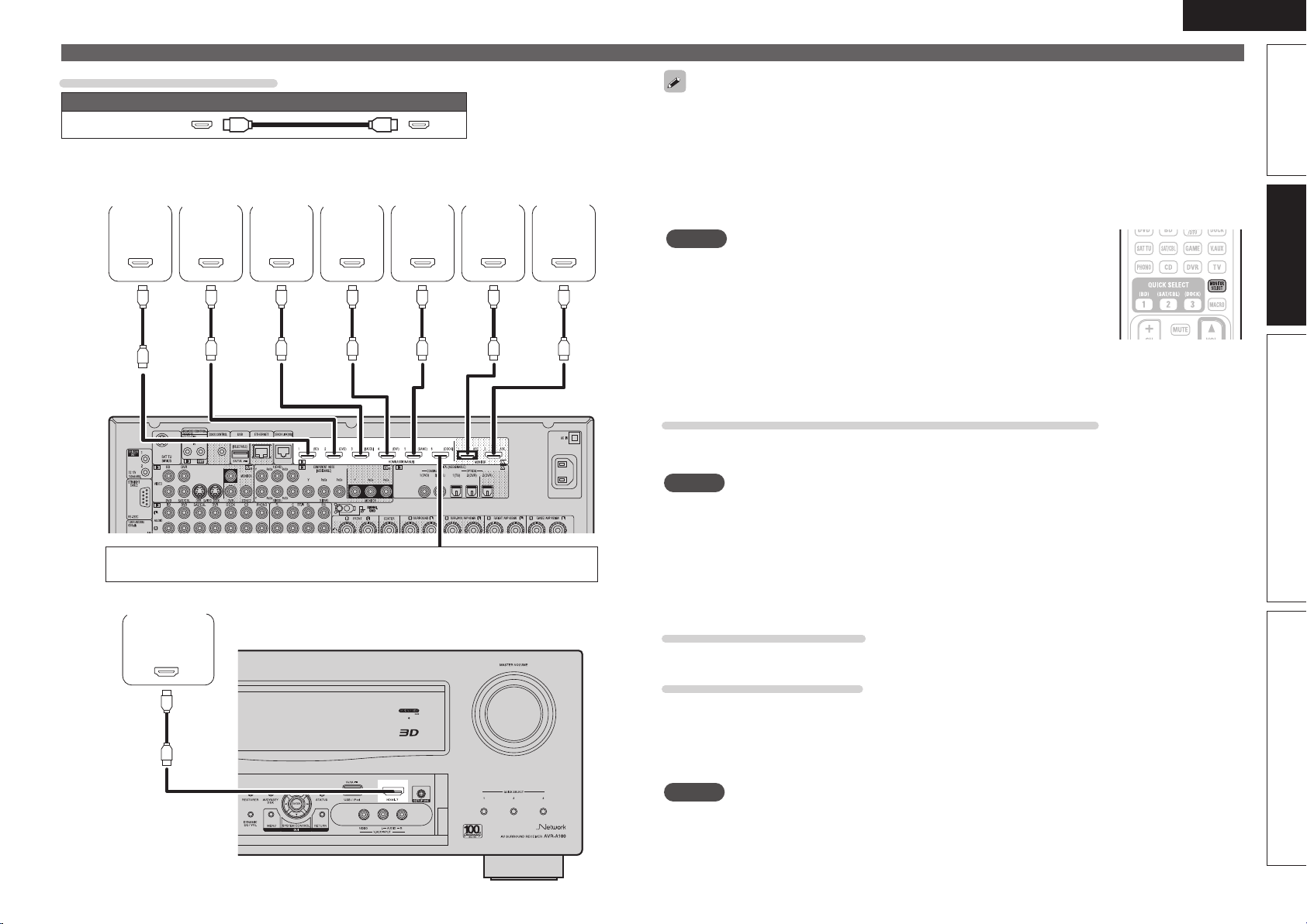
Cables used for connections
Audio and video cable (sold separately)
HDMI cable
• This interface allows transfer of digital video signals and digital audio signals over a single HDMI cable.
OUT
HDMI
OUT
HDMI
OUT
HDMI
OUT
HDMI
OUT
HDMI
IN
HDMI
IN
HDMI
Blu-ray
Disc
player
DVD
player
TV 1
GRear panelH
Set-top
box
Digital
video
recorder
Game
console
TV 2
When a control dock for iPod is not used, you can connect other HDMI-compatible
devices.
OUT
HDMI
Digital
camcorder
GFront panelH
1.AVRA100E3_ENG_1st_0824.indd 17 2010/08/26 17:47:20
18
ENGLISH
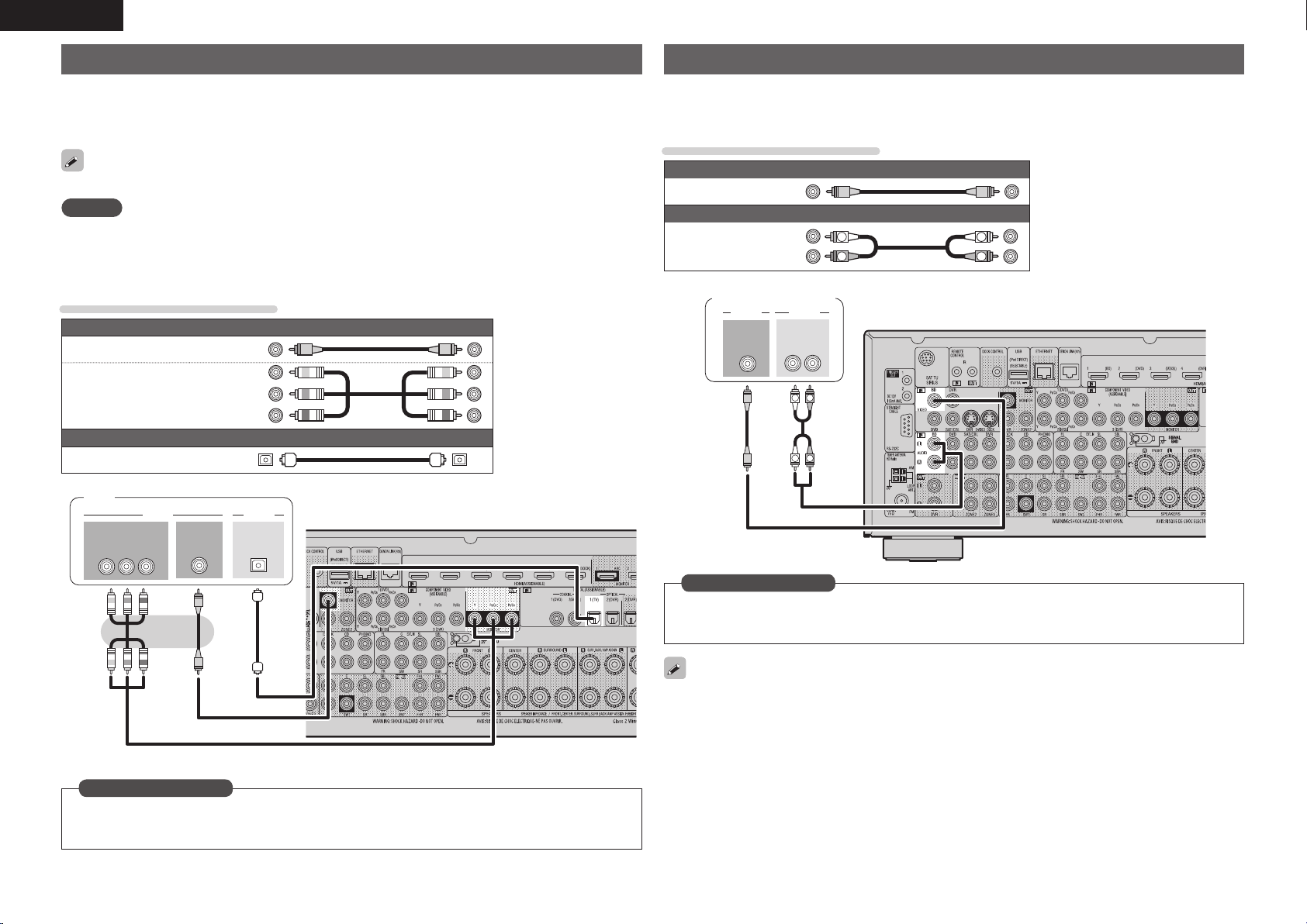
Connecting a TV
• Select the connector to use and connect the device.
• For video connections, see “Converting input video signals for output (Video conversion function)”
(vpage15).
• For instructions on HDMI connections, see “Connecting an HDMI-compatible device” (vpage16).
To listen to TV audio through this device, use the optical digital connection.
NOTE
The optical connection is not required when a TV compatible with the ARC function (Audio Return Channel
(HDMI 1.4a standard function) is connected to this unit via an HDMI connection.
For details, see “About ARC (Audio Return Channel) function” (vpage16) or refer to the instruction
manual for your TV.
Cables used for connections
Video cable (sold separately)
Video cable
(Yellow)
Component video
cable
(Green)
(Blue)
(Red)
Audio cable (sold separately)
Optical cable
IN
VIDEO
AUDIO
OPTICAL
OUT
VIDEO
COMPONENT VIDEO
YP
BPR
IN
TV
Set this to change the digital input connector or component video input connector to which the input
source is assigned.
“Input Assign” (vpage82)
in Set as Necessary
Connecting a Blu-ray Disc player
• You can enjoy video and audio from a Blu-ray Disc.
• Select the connector to use and connect the device.
• For instructions on HDMI connections, see “Connecting an HDMI-compatible device” (vpage16).
Cables used for connections
Video cable (sold separately)
Video cable
(Yellow)
Audio cables (sold separately)
Audio cable
(White)
(Red)
R
L
R
L
R
L
R
L
VIDEO
AUDIO
AUDIO
RL
OUT
OUT
VIDEO
Blu-ray Disc player
Set this to change the digital input connector or component video input connector to which the input
source is assigned.
“Input Assign” (vpage82)
in Set as Necessary
For HD audio (Dolby TrueHD, DTS-HD, Dolby Digital Plus and DTS Express) playback, connect with HDMI
(vpage16 “Connecting an HDMI-compatible device”).
1.AVRA100E3_ENG_1st_0824.indd 18 2010/08/26 17:47:22
19
Simple version Advanced version Information
ENGLISH
Basic version
Connecting a DVD player
• You can enjoy video and audio from a DVD.
• Select the connector to use and connect the device.
• For instructions on HDMI connections, see “Connecting an HDMI-compatible device” (vpage16).
Cables used for connections
Video cable (sold separately)
Video cable
(Yellow)
Component
video cable
(Green)
(Blue)
(Red)
Audio cables (sold separately)
Audio cable
(White)
(Red)
R
L
R
L
Coaxial
digital cable
(Orange)
R
L
R
L
VIDEOAUDIO
AUDIO
RL
OUT
OUT
VIDEO
COMPONENT VIDEO
YP
BPR
OUT
OUT
COAXIAL
DVD player
Set this to change the digital input connector or component video input connector to which the input
source is assigned.
“Input Assign” (vpage82)
in Set as Necessary
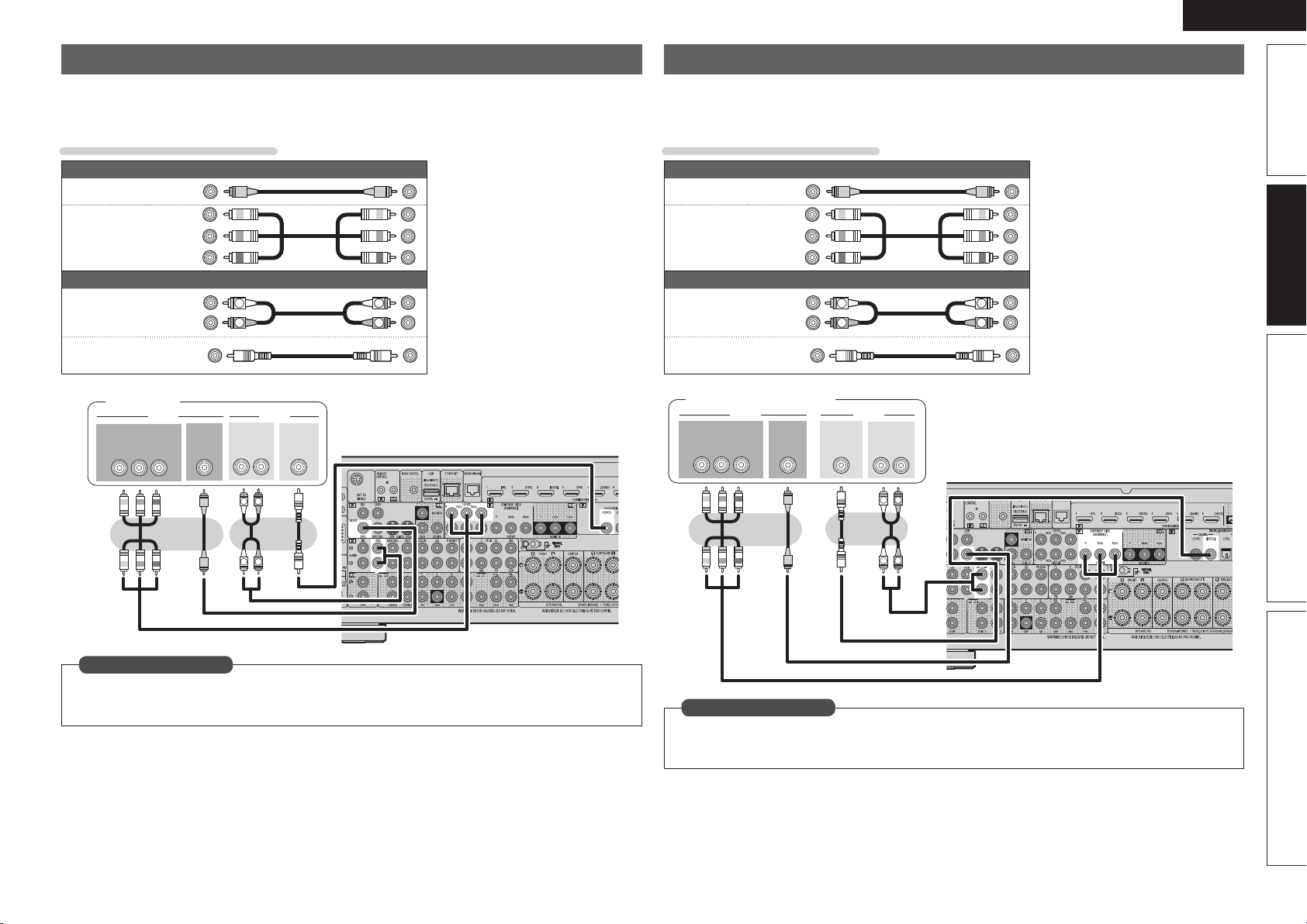
Connecting a set-top box (Satellite tuner/cable TV)
• You can watch satellite or cable TV.
• Select the connector to use and connect the device.
• For instructions on HDMI connections, see “Connecting an HDMI-compatible device” (vpage16).
Cables used for connections
Video cable (sold separately)
Video cable
(Yellow)
Component
video cable
(Green)
(Blue)
(Red)
Audio cables (sold separately)
Audio cable
(White)
(Red)
R
L
R
L
Coaxial
digital cable
(Orange)
R
L
R
L
VIDEO
AUDIO
AUDIO
RL
OUT
OUT
VIDEO
COMPONENT VIDEO
YP
BPR
OUT
OUT
COAXIAL
Satellite tuner/Cable TV
Set this to change the digital input connector or component video input connector to which the input
source is assigned.
“Input Assign” (vpage82)
in Set as Necessary
1.AVRA100E3_ENG_1st_0824.indd 19 2010/08/26 17:47:25
20
ENGLISH
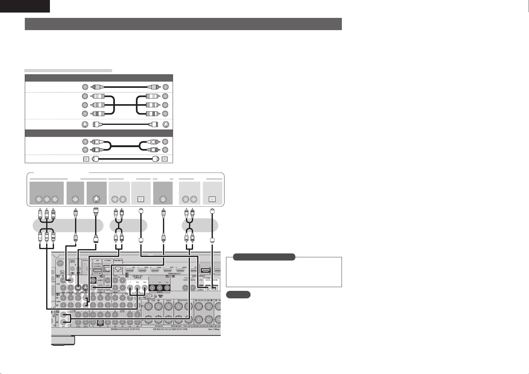
Connecting a digital video recorder
• You can record video onto a Blu-ray Disc or DVD.
• Select the connector to use and connect the device.
• When recording analog audio, use the analog connection.
• See “REC OUT mode” (vpage67) for operating instructions.
• For instructions on HDMI connections, see “Connecting an HDMI-compatible device” (vpage16).
Cables used for connections
Video cable (sold separately)
Video cable
(Yellow)
Component
video cable
(Green)
(Blue)
(Red)
S-Video cable
Audio cable (sold separately)
Audio cable
(White)
(Red)
R
L
R
L
Optical cable
R
L
R
L
R
L
R
L
RLRL
OUT
IN
AUDIOVIDEOVIDEO
OUT
IN
OPTICALOPTICAL
IN
AUDIOAUDIO
OUT
VIDEO
OUT
S-VIDEOVIDEO
COMPONENT VIDEO
YP
BPR
OUT
AUDIO
Digital video recorder
NOTE
To record video signals through this unit, use the
video cable for connection between this unit and the
player.
Set this to change the digital input connector or
component video input connector to which the
input source is assigned.
“Input Assign” (vpage82)
in Set as Necessary
1.AVRA100E3_ENG_1st_0824.indd 20 2010/08/26 17:47:26
21
Simple version Advanced version Information
ENGLISH
Basic version
Connecting a digital camcorder
• You can enjoy video and audio from a digital camcorder.
• You can enjoy games by connecting a game machine via the V.AUX input connector. In this case, select
the input source to “V.AUX”.
• For instructions on HDMI connections, see “Connecting an HDMI-compatible device” (vpage16).
Cables used for connections
Video cable (sold separately)
Video cable
(Yellow)
Audio cable (sold separately)
Audio cable
(White)
(Red)
R
L
R
L
R
L
R
L
OUT
AUDIOVIDEO
VIDEO
AUDIO
RL
OUT
Digital camcorder
Set this to change the digital input connector or component video input connector to which the input
source is assigned.
“Input Assign” (vpage82)
in Set as Necessary
NOTE
When a non-standard video signal from a game machine or some other source is input, the video conversion
function might not operate. In this case, use the monitor output of the same connector as the input.
Connecting a control dock for iPod
• Connect a control dock for iPod to the unit to enjoy video and music stored on an iPod.
• For a control dock for iPod, use ASD-1R and ASD-11R made by DENON (sold separately).
• For instructions on the control dock for iPod settings, refer to the control dock for iPod’s operating
instructions.
R
L
R
L
ASD-11R
Control dock for iPod
Use the AV/Control
Cable supplied with
the DENON control
dock for iPod.
You can also connect the iPod you are using directly to the USB port of this unit (vpage22 “Connecting
an iPod or USB memory device to the USB port”).
NOTE
When connecting an iPhone to this unit, keep the iPhone at least 20 cm away from this unit. If the iPhone is
kept closer to this unit and a telephone call is received by the iPhone, noise may be output from this device.
1.AVRA100E3_ENG_1st_0824.indd 21 2010/08/26 17:47:27
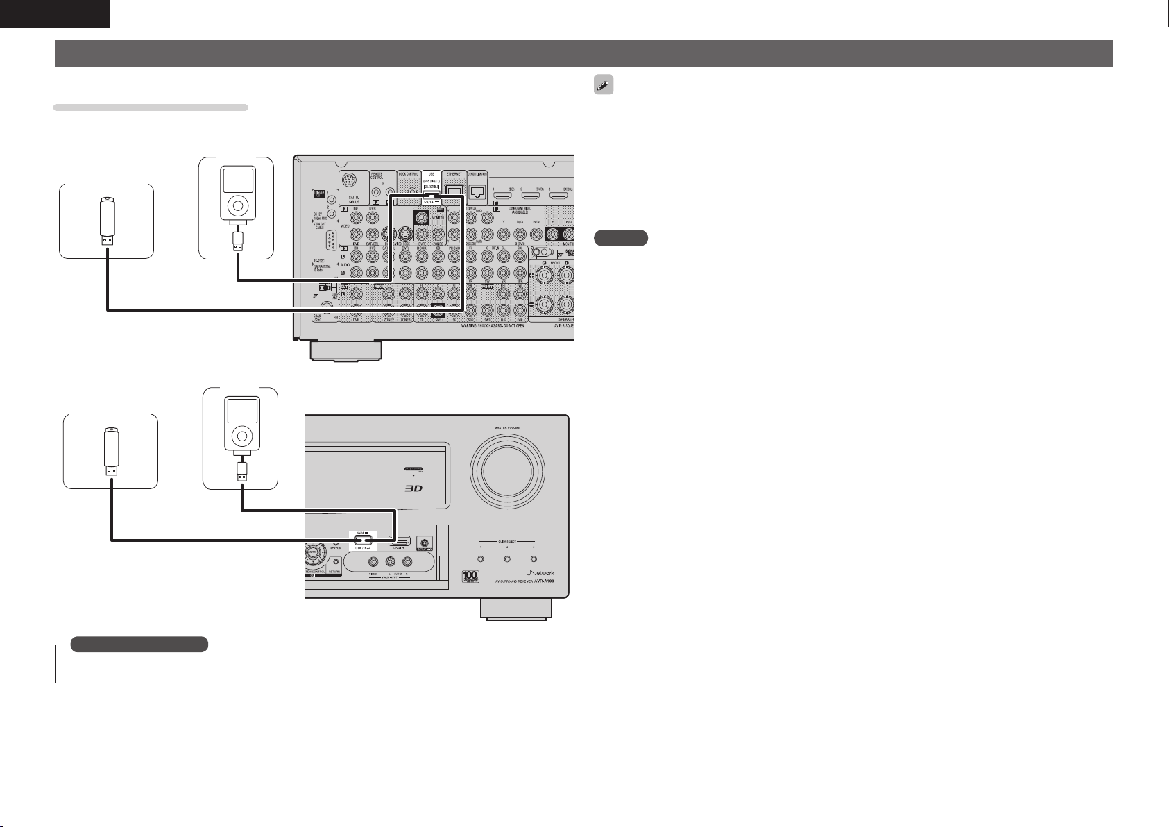
22
ENGLISH
• In the initial status, USB memory devices can be used by connecting them to the USB port on the front
panel.
• When you want to playback a video file stored on an iPod, use a DENON control dock for iPod (ASD-1R
and ASD-11R, sold separately) (vpage21 “Connecting a control dock for iPod”).
• With iPods, playback is possible with iPhone, iPod touch, classic and nano released from the 5th-generation
of iPods. For details, check the DENON web site or page 32.
• DENON does not guarantee that all USB memory devices will operate or receive power. When using
a portable USB connection type HDD of the kind to which an AC adapter can be connected to supply
power, use the AC adapter.
NOTE
• You cannot use the USB ports on the front panel and rear panel simultaneously. Select and connect the
USB port to use.
• USB memory devices will not work via a USB hub.
• Do not use an extension cable when connecting a USB memory device. This may cause radio interference
with other devices.
• This unit does not support playback on an iPad. Do not connect an iPad to the unit.
Connecting an iPod or USB memory device to the USB port
You can enjoy music stored on an iPod or USB memory device.
Cables used for connections
To connect an iPod to this unit, use the USB cable supplied with the iPod.
USB memory
device
iPod
or
GRear panelH
USB memory
device
iPod
or
GFront panelH
Set when you change the USB port to use.
“USB Select” (vpage85)
in Set as Necessary
1.AVRA100E3_ENG_1st_0824.indd 22 2010/08/26 17:47:27
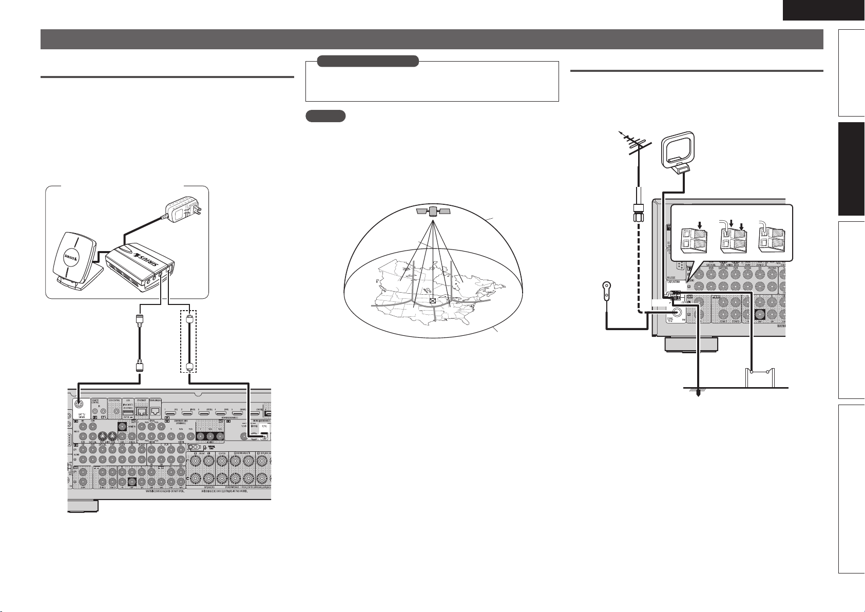
23
Simple version Advanced version Information
ENGLISH
Basic version
Connecting an antenna
Connecting a SIRIUS connector
• This unit is a SIRIUS Satellite Radio Ready
®
receiver. You can
receive SIRIUS
®
Satellite Radio by connecting to the SiriusConnect
Home Tuner and subscribing to the SIRIUS service.
• Plug the SIRIUS connector on the SIRIUS service.
• Position the Home Tuner antenna near a south-facing window to
receive the best signal.
For details, see “Listening to SIRIUS satellite radio” (vpage33).
When making connections, also refer to the operating instructions
of the SiriusConnect Home Tuner.
SiriusConnect Home Tuner
When
connecting
digital audio
When connecting digital of the SiriusConnect Home Tuner,
perform the setting “Digital”.
“Input Assign” (vpage82)
in Set as Necessary
NOTE
Keep the power cord unplugged until the SiriusConnect Home Tuner
connection have been completed.
n Positioning the antenna
For a consistent satellite signal, the antenna must be positioned
correctly. Use the following map to determine which area you are
in and position the antenna accordingly.
q
w
e
r
t
SOUTH
NORTH
WEST
SKY
EAST
HORIZON
Area 1 Point the antenna toward the sky in the east, northeast, or
southeast, either through a window or outside.
Area 2 Point the antenna toward the sky in the north or northeast,
either through a window or outside.
Area 3 Point the antenna toward the sky in the north or northwest,
either through a window or outside.
Area 4 Point the antenna toward the sky in the west, northwest, or
southwest, either through a window or outside.
Area 5 Put the antenna outside and point it straight up. The antenna
cannot be used indoors.
Connecting an HD Radio receiver
• By connecting a HD Radio antenna to this unit, you can receive
HD Radio programs.
• HD Radio broadcasting currentry is available in the United States and
select other countries.
w eq
FM outdoor
antenna
Direction of broadcasting station
75 Ω coaxial
cable
Ground
AM outdoor
antenna
AM loop antenna
(for HD Radio broadcasting,
supplied)
• To prevent interference, install
at least 3.3 ft/1 m away from the
antenna connected to the this
unit’s other AM tuner terminal.
Black
White
FM indoor
antenna (for
HD Radio
broadcasting,
supplied)
1.AVRA100E3_ENG_1st_0824.indd 23 2010/08/26 17:47:28
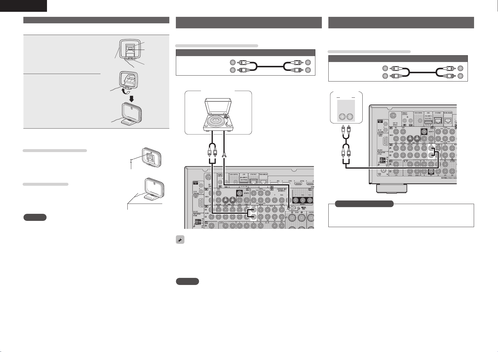
24
ENGLISH
Connecting a CD player
• You can enjoy CD sound.
• Select the connector to use and connect the device.
Cables used for connections
Audio cable (sold separately)
Audio cable
(White)
(Red)
R
L
R
L
R
L
R
L
AUDIO
AUDIO
RL
OUT
CD player
Set this to change the digital input connector to which the input
source is assigned.
“Input Assign” (vpage82)
in Set as Necessary
Connecting a record player
You can enjoy playing records.
Cables used for connections
Audio cable (sold separately)
Audio cable
(White)
(Red)
R
L
R
L
GND
AUDIO
OUT
R
L
Turntable
(MM cartridge)
• This unit is compatible with record players with an MM cartridge.
When you connect to a record player with an MC cartridge, use a
commercially available MC head amp or a step-up transformer.
• When you increase the volume without connecting the record
player, there may be “booming” noise from the speakers.
NOTE
The SIGNAL GND terminal of this unit is not a safety ground
connection. Connect it to reduce noise when noise is excessive.
Note that depending on the record player, connecting the ground line
may have the reverse effect of increasing noise. In this case, it is not
necessary to connect the ground line.
n AM loop antenna assembly
1
Put the stand section
through the bottom of
the loop antenna from
the rear and bend it
forward.
Stand
Square
hole
Projecting
part
Loop
antenna
2
Insert the projecting
part into the square hole
in the stand.
n Using the AM loop antenna
Suspending on a wall
Suspend directly on a wall without assembling.
Nail, tack, etc.
Standing alone
Use the procedure shown above to assemble.
NOTE
• Do not connect two FM antennas simultaneously.
• Even if an external AM antenna is used, do not disconnect the AM
loop antenna.
• Make sure the AM loop antenna lead terminals do not touch metal
parts of the panel.
• If the signal has noise interference, connect the ground terminal
(GND) to reduce noise.
• If you are unable to receive a good broadcast signal, we recommend
installing an outdoor antenna. For details, inquire at the retail store
where you purchased the unit.
Connecting an antenna
1.AVRA100E3_ENG_1st_0824.indd 24 2010/08/26 17:47:29
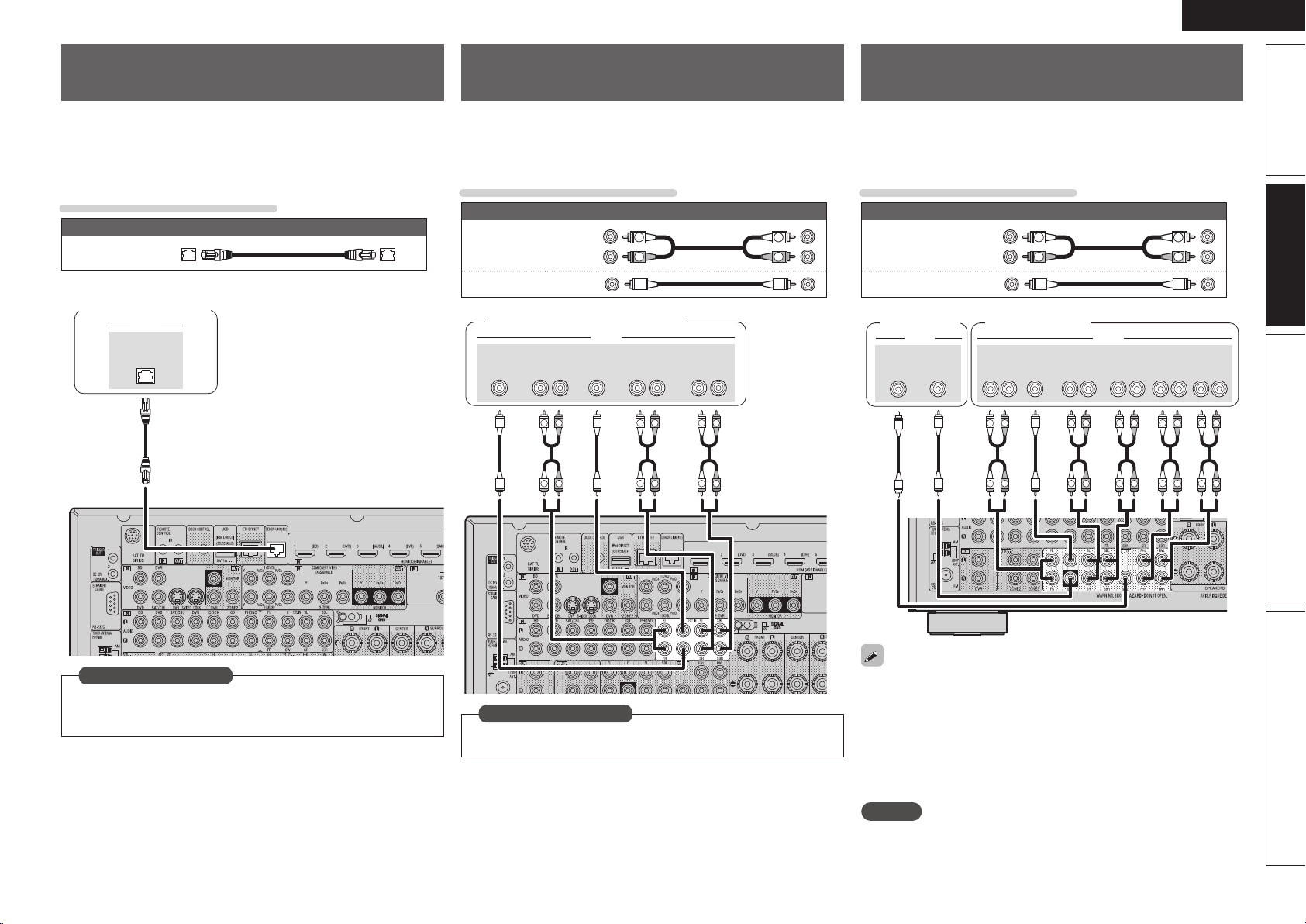
25
Simple version Advanced version Information
ENGLISH
Basic version
Connecting a external power
amplifier
• You can use this unit as a pre-amp by connecting a commercially
available power amp to the PRE OUT connector. Adding a power amp
to each of the channels provides an even greater sound presence.
• Select the terminal to use and connect the device.
Cables used for connections
Audio cable (sold separately)
Audio cable
(White)
(Red)
R
L
R
L
Audio cable
R
L
R
L
R
L
R
L
R
L
R
L
R
L
R
L
R
L
R
L
SUB-
WOOFER
1
SUB-
WOOFER
2
CENTERSURROUND
BACK
RL
SURROUND
RL
FRONT
HEIGHT
RL
FRONT
WIDE
RL
FRONT
RL
AUDIOAUDIO
Power amplifierSubwoofer
• When using just one surround back speaker, connect it to the left
channel (L) terminal.
• Use the volume control on the subwoofer to control subwoofer
volume.
• If the subwoofer volume sounds low, use the volume control
provided on the subwoofer to adjust the volume.
• You can use this unit as a preamplifier. For details, see “PRE AMP
mode” (vpage62).
NOTE
When external power amplifier have been connected to PRE OUT
terminals, do not connect the speakers to the speaker terminals.
Component equipped with a DENON
LINK connector
Multichannel playback is possible. That includes DVD-Audio and Super
Audio CD (vpage30 “Playing an iPod®”).
Also, refer to page29 “Playing a Blu-ray Disc player compatible with
DENON LINK 4th” for information on connecting a player that supports
DENON LINK 4th edition.
Cables used for connections
Audio cable (sold separately)
DENON LINK
cable
DENON LINK
AUDIO
Blu-ray Disc player /
DVD player
When connecting by use of DENON LINK, set “Digital” to
“D.LINK”.
“Input Assign” (vpage82)
in Set as Necessary
Component with Multi-channel
Output connectors
• You can connect this unit to an external device fitted with multi-
channel sound audio output jacks to enjoy music and video.
• The video signal can be connected in the same way as a Blu-ray Disc
player / DVD player (vpage18 “Connecting a Blu-ray Disc player”).
Cables used for connections
Audio cable (sold separately)
Audio cable
(White)
(Red)
R
L
R
L
Audio cable
R
L
R
L
R
L
R
L
R
L
R
L
SUB-
WOOFER
CENTERSURROUND
BACK
RL
SURROUND
RL
FRONT
RL
AUDIO
Blu-ray Disc player / DVD player
To play analog signals input from the external input (EXT. IN)
terminal, set “Input Mode” (vpage84) to “EXT. IN”.
in Set as Necessary
1.AVRA100E3_ENG_1st_0824.indd 25 2010/08/26 17:47:30
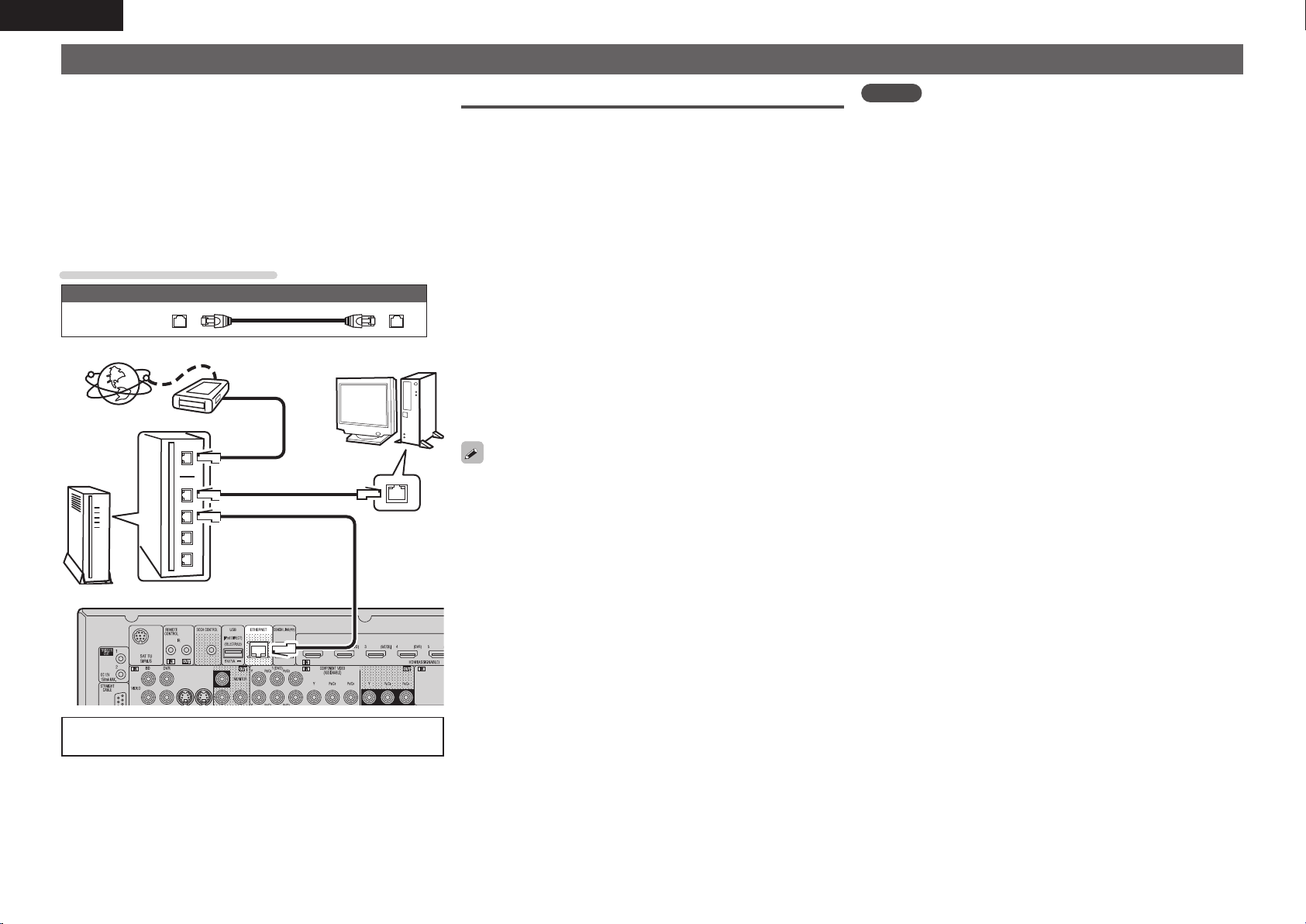
26
ENGLISH
Connecting to a home network (LAN)
• This unit lets you play via your home network (LAN) music files
stored on a computer and music content such as that from Internet
radio.
You can also operate this unit from a computer using the Web
control function.
• You can update by downloading the latest firmware from the
DENON website.
For more information, on the menu, select “Firmware Update”
(vpage106).
• See “Network Setup” on the menu (vpage101) for more information
on network setting.
Cables used for connections
Cable (sold separately)
Ethernet
cable
Internet
To WAN side
Router
To LAN port
To LAN port
LAN port/
Ethernet
connector
Computer
Modem
For connections to the Internet, contact an ISP (Internet
Service Provider) or a computer shop.
Required system
n Broadband internet connection
n Modem
Device that connects to the broadband circuit and conducts
communications on the Internet.
A type that is integrated with a router is also available.
n Router
When using this unit, we recommend you use a router equipped
with the following functions:
• Built-in DHCP server
This function automatically assigns IP addresses on the LAN.
• Built-in 100BASE-TX switch
When connecting multiple devices, we recommend a switching
hub with a speed of 100 Mbps or greater.
n Ethernet cable (CAT-5 or greater recommended)
• Use only shielded STP or ScTP LAN cable which is available at
retailer.
• Some flat type Ethernet cables are easily affected by noise.
We recommend using a normal type cable.
• If you have an Internet provider contract for a line on which network
settings are made manually, make the settings at “Network Setup”
(vpage101).
• With this unit, it is possible to use the DHCP and Auto IP functions
to make the network settings automatically.
• When using this unit with the broadband router’s DHCP function
enabled, this unit automatically performs the IP address setting and
other settings.
When using this unit connected to a network with no DHCP
function, make the settings for the IP address, etc., at “Network
Setup” (vpage101).
• When setting manually, check the setting contents with the network
administrator.
NOTE
• A contract with an ISP is required to connect to the Internet.
No additional contract is needed if you already have a broadband
connection to the Internet.
• The types of routers that can be used depend on the ISP. Contact an
ISP or a computer shop for details.
• DENON assumes no responsibility whatsoever for any
communication errors or troubles resulting from customer’s
network environment or connected devices.
• This unit is not compatible with PPPoE. A PPPoE-compatible router
is required if you have a contract for a type of line set by PPPoE.
• Do not connect an ETHERNET connector directly to the LAN port/
Ethernet connector on your computer.
1.AVRA100E3_ENG_1st_0824.indd 26 2010/08/26 17:47:31
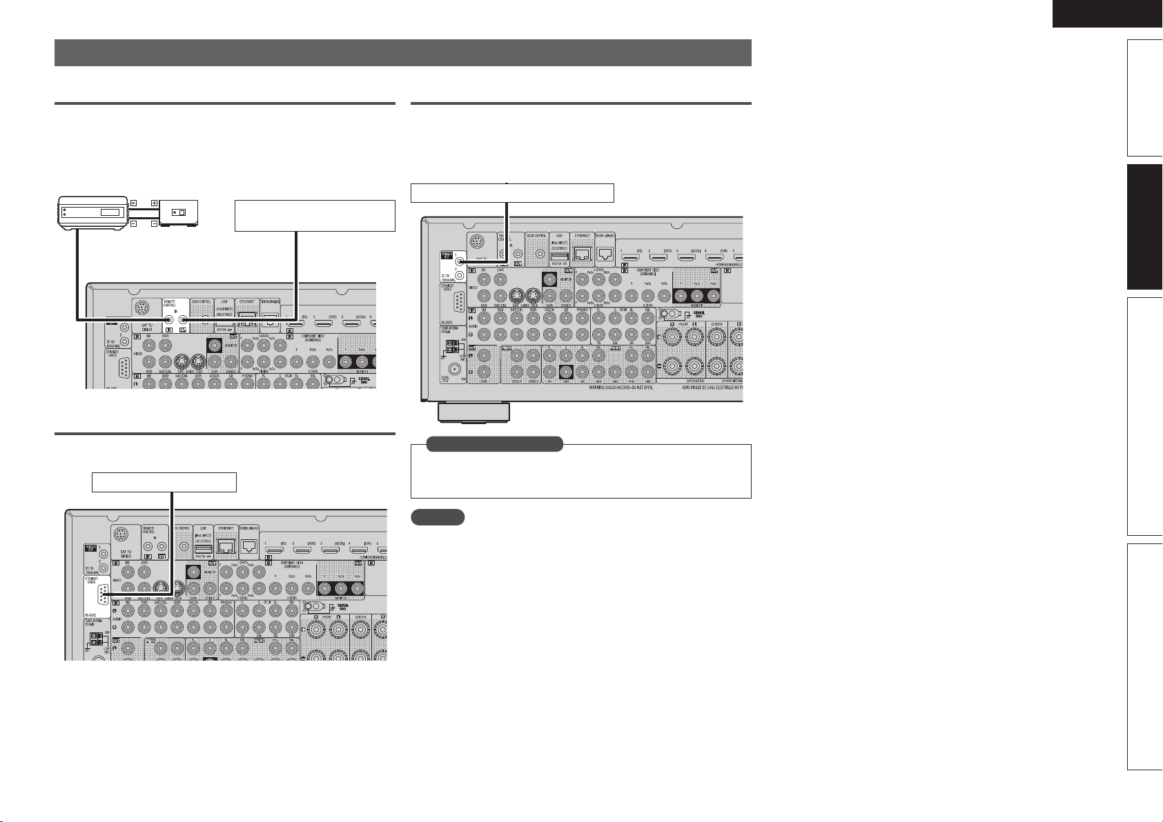
27
Simple version Advanced version Information
ENGLISH
Basic version
Connecting an external control device
REMOTE CONTROL jacks
If this unit is installed in a location that is out of range of the signal
from the remote control unit, you can still operate the unit and the
devices connected to it by using a commercially available IR receiver.
You can also use it to remotely control ZONE2, ZONE3 (another room).
AUX
OUT
Device equipped with a
REMOTE CONTROL IN jack
Infrared
retransmitter
Infrared
sensor
Output
Input
RS-232C connector
When you connect an external control device, you can control this unit
with the external control device.
External serial controller
Perform the operation below beforehand.
q Turn on the power of this unit.
w Turn off the power of this unit from the external controller.
e Check that the unit is in the standby mode.
TRIGGER OUT jacks
When a device with TRIGGER IN jack is connected, the connected
device’s power on/standby can be controlled through linked operation
to this unit.
The TRIGGER OUT jack outputs a maximum 12 V/150 mA electrical
signal.
12 V/150 mA trigger-compatible device
Set to change the conditions for linked operation via the TRIGGER
OUT 1 or 2 jack.
“Trigger Out 1” or “Trigger Out 2” (vpage105)
in Set as Necessary
NOTE
• Use the monaural mini-plug cable for connecting TRIGGER OUT
jacks. Do not use the stereo mini-plug cable.
• If the permissible trigger input level for the connected device is larger
than 12V/150mA, or has shorted, the TRIGGER OUT jack cannot be
used. In this case, turn off the power to the unit, and disconnect it.
1.AVRA100E3_ENG_1st_0824.indd 27 2010/08/26 17:47:32
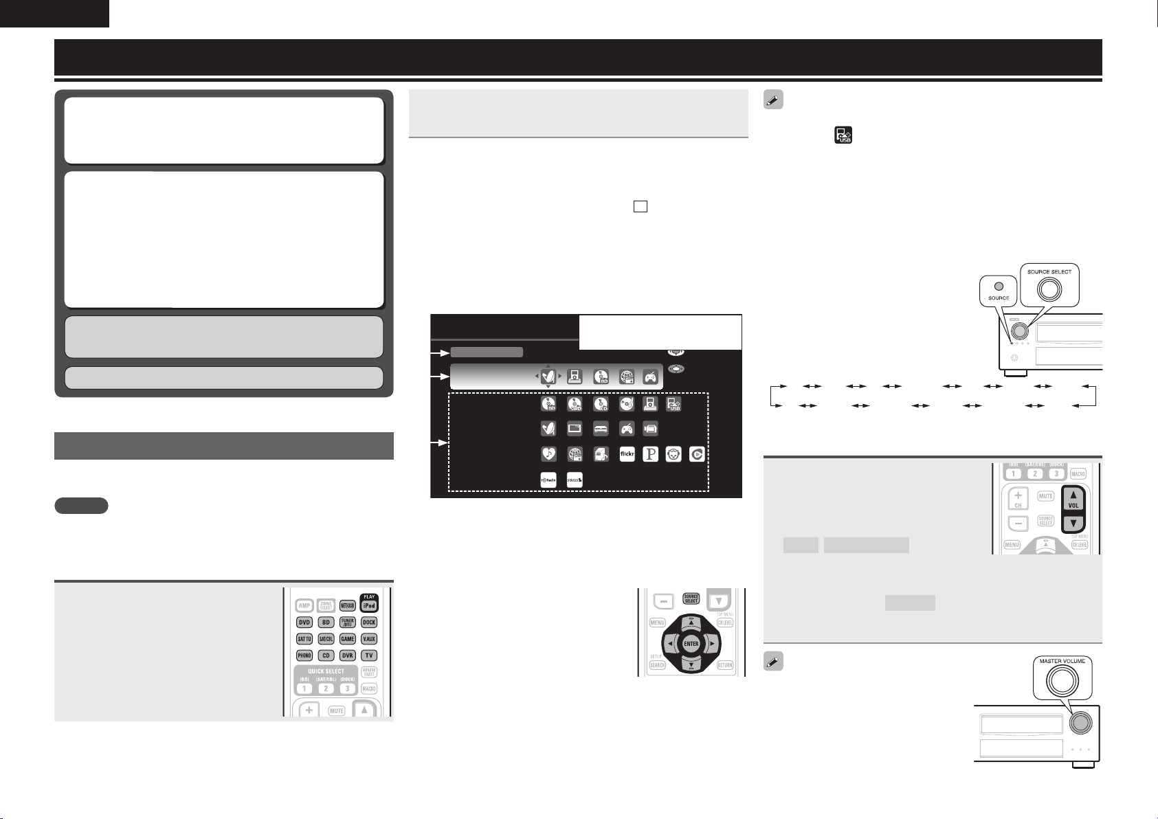
28
ENGLISH
Playback (Basic operation)
n Playing a Blu-ray Disc player/DVD player
(vpage29)
n Playing a CD player (vpage30)
n Playing an iPod
®
(vpage30)
n Tuning in radio stations (vpage33)
n Playing a network audio (vpage37)
n Playing a USB memory device (vpage48)
Selecting a listening mode (Surround Mode)
(vpage50)
n Selecting the input source (vpage28)
n Adjusting the master volume (vpage28)
n Turning off the sound temporarily (vpage29)
Playback (Advanced operation) (vpage65)
Important information
Before starting playback, make the connections between the different
components and the settings on the receiver.
NOTE
Also refer to the operating instructions of the connected components
when playing them.
Selecting the input source
Press the input source select button
(NET/USB, iPod, DVD, BD,
TUNER/DTU, DOCK, SAT TU,
SAT/CBL, GAME, V.AUX, PHONO,
CD, DVR, TV) to be played back.
The desired input source can be selected
directly.
Display the selected input source name on
the remote control unit.
• When iPod PLAY is pressed, the input source of this unit is
switched to “DOCK” or “NET/USB” and the connected iPod is
automatically played (vpage33 “iPod play function”).
You can also use the following operation to select an input
source.
n Using the “SOURCE SELECT” menu
Switch the main remote control unit to the
M
(MAIN ZONE) mode
when performing this operation (vpage108 “Operating the main
remote control unit”).
If the main remote control unit is in “ZONE2”or “ZONE3” mode,
the “SOURCE SELECT” menu will not be displayed when SOURCE
SELECT
is pressed.
q Press SOURCE SELECT.
Display the “SOURCE SELECT” menu.
SOURCE SELECT
Source
SAT/CBL
Recent
Player
Video
Network
Tuner
Enter
Move
The currently selected input
source is highlighted.
q
w
e
q Input Source
The name of the highlighted input source is displayed.
w Recently used sources
The recently used input sources (up to fi ve) are displayed.
e Icons for the input sources in the different categories are
displayed.
w Use uio p to select the input source,
then press ENTER.
The input source is set and the source
selection menu is turned off.
• When using with an iPod connected directly to the USB port of this
unit, select “ (USB/iPod)” for the input source.
• Input sources that are not going to be used can be set ahead of time.
Make this setting at “Source Delete” (vpage104).
• To turn off the source selection menu without selecting an input
source, press SOURCE SELECT again.
• When SOURCE SELECT is pressed, the AMP-operation mode starts
automatically (vpage108).
n Using the knob on the main unit
Turn SOURCE SELECT.
• If “Rec Select” or “Tuning Preset”
mode is selected for the input
source, press SOURCE before
turning SOURCE SELECT.
• Turning SOURCE SELECT switches
the input source, as shown below.
BD DVD TV SAT/CBL GAMEDVR V.AUX
PHONO HD Radio SIRIUS NET/USB DOCKCD
Adjusting the master volume
Use VOL df to adjust the volume.
n When the “Volume Display” setting
(vpage104) is “Relative”
GAdjustable rangeH
– – –
–80.5dB – 18.0dB
n When the “Volume Display” setting (vpage104) is
“Absolute”
GAdjustable rangeH
0.0 – 99.0
• The variable range differs according to the input signal and channel
level setting.
You can also operate via the main unit.
In this case, perform the following
operations.
Turn MASTER VOLUME to adjust the
volume.
1.AVRA100E3_ENG_1st_0824.indd 28 2010/08/26 17:47:34
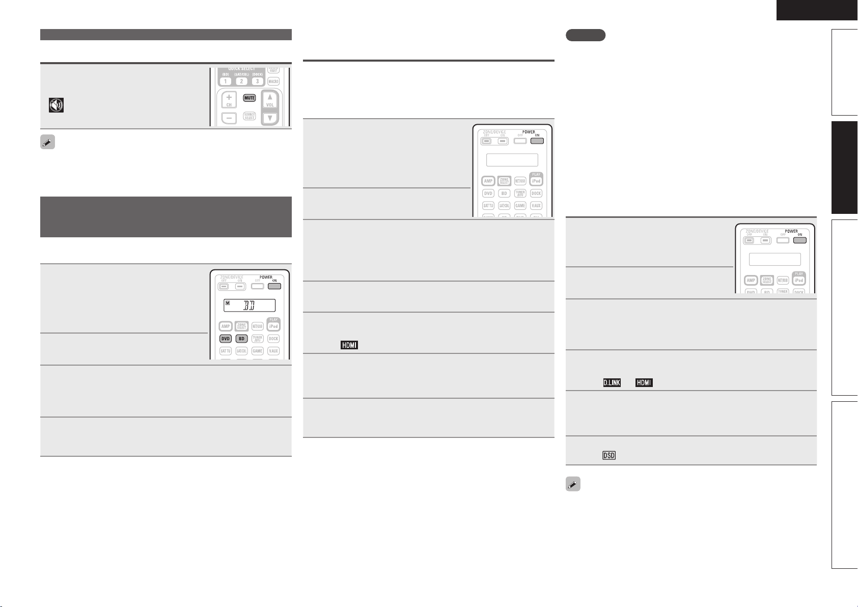
29
Simple version Advanced version Information
ENGLISH
Basic version
Turning off the sound temporarily
Press MUTE.
• The power indicator flashes green.
• “MUTE” indicator on the display lights.
•
appears on a TV screen.
• The sound is reduced to the level set at “Mute Level” (vpage104).
• To cancel, press MUTE again. Muting can also be canceled by
adjusting the master volume.
Playing a Blu-ray Disc player/DVD
player
The following describes the procedure for playing Blu-ray Disc player/
DVD player.
1
Prepare for playback.
q Turn on the power of the TV,
subwoofer and player.
w Change the TV input to the input of
this unit.
e Load the disc in the player.
2
Press POWER ON to turn on
power to the unit.
3
Press BD or DVD to switch an input source for a
player used for playback.
The selected input source name appears on the remote control
unit.
4
Play the component connected to this unit.
Make the necessary settings on the player (language setting,
subtitles setting, etc.) beforehand.
Playing a Blu-ray Disc player compatible
with DENON LINK 4th
• DENON LINK 4th uses the clock of the AV amplifier connected by
DENON LINK to achieve HDMI signal transfer with low jitter when
playing BD.
• To play DENON LINK 4th signals, make HDMI and DENON LINK
connections with a compatible Blu-ray disc player.
1
Prepare for playback.
q Turn on the power of the TV,
subwoofer and player.
w Change the TV input to the input of
this unit.
e Load the disc in the player.
2
Press POWER ON to turn on
power to the unit.
3
Perform the settings of the “Input Assign” menu
(vpage 82).
q Assign HDMI connectors for the input source (example:
BD).
w Set “DIGITAL” to “D.LINK”.
4
Set “HDMI Control” – “Control” (vpage 99) to
“ON”.
5
Press the input source select button (example: BD) to
switch an input source assigned in step 3 - q.
The
indicator lights on the display.
6
Set the audio input mode to “Auto” using the “Input
Mode” menu (vpage 84).
• The default setting of “Input Mode” is “Auto”.
7
Play the component connected to this unit.
Make the necessary settings on the player (language setting,
subtitles setting, etc.) beforehand.
NOTE
• Set the Blu-ray disc player’s “DENON LINK” setting to “4th”. For
instructions on operation, refer to the Blu-ray disc player’s manual.
• The low jitter transmission function does not work except during
Blu-ray disc playback. In this case, the video signal is output from
the HDMI OUT terminal, and the audio signal from the DENON LINK
terminal.
• When a Blu-ray disc is played with the input mode set to “Auto”,
playback is performed in the DENON LINK 4th mode. When a disc
other than a Blu-ray disc is played with the input mode set to “Auto”,
playback is automatically performed in the DENON LINK 3rd mode.
• When the input mode is set to “HDMI”, normal HDMI playback is
performed.
• When the input mode is set to “Digital”, playback is fixed to the
DENON LINK 3rd mode and BDs cannot be played.
Playing Super Audio CD
1
Prepare for playback.
q Turn on the power of the TV,
subwoofer and player.
w Load the disc in the player.
2
Press POWER ON to turn on
power to the unit.
3
Perform the settings of the “Input Assign” menu
(vpage 82).
Assign HDMI connectors for the input sources (example: DVD).
Or set “DIGITAL” to “D.LINK”.
4
Press the input source select button (example: DVD)
to switch an input source assigned in step 3.
The
or indicator lights on the display.
5
Set the audio input mode to “Auto” using the “Input
Mode” menu (vpage 84).
• The default setting of “Input Mode” is “Auto”.
6
Play the component connected to this unit.
The
indicator lights on the display.
• When playing DSD signals in the DIRECT or PURE DIRECT mode,
the DSD signals are converted into analog signals directly. When
you play back an audio track using other surround modes or process
downmix, at first convert DSD signals into the PCM format and then
convert into analog signals.
• “DSD DIRECT” is shown on the display when playing DSD signals
in the DIRECT mode.
Important information
1.AVRA100E3_ENG_1st_0824.indd 29 2010/08/26 17:47:34
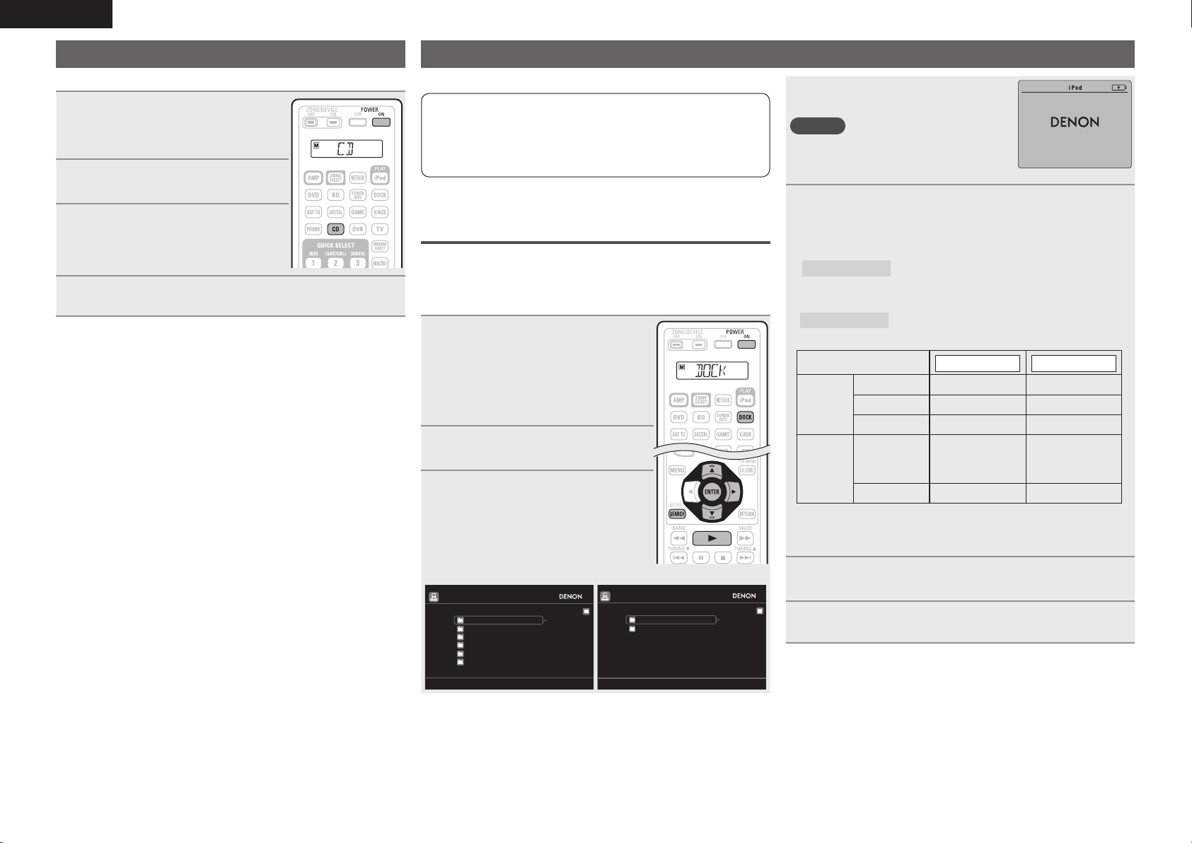
30
ENGLISH
Playing a CD player
The following describes the procedure for playing CD player.
1
Prepare for playback.
q Turn on the power of the subwoofer
and player.
w Load the disc in the player.
2
Press POWER ON to turn on
power to the unit.
3
Press CD to switch the input
source to the CD player.
“CD” appears on the remote control
unit.
4
Play the component connected to this unit.
Playing an iPod
®
There are two methods for iPod playback.
q Use a DENON control dock for iPod to play back.
You can play back both video, photo and audio.
w Connect an iPod directly to the USB port to play back
(vpage32).
You can play back audio only.
q
Use a DENON control dock for iPod to
play back
DENON control dock for iPod usable on this unit
• ASD-1R / ASD-11R
n Listening to music on an iPod
®
1
Prepare for playback.
q Connect the DENON control dock
for iPod to this unit (vpage21
“Connecting a control dock for
iPod”).
w Set the iPod
®
in the DENON control
dock for iPod.
2
Press POWER ON to turn on
power to the unit.
3
Press DOCK to switch the input
source to “DOCK”.
• If ”Browse mode” is selected in step
4, the following screen is displayed on a
TV screen, depending on the connected
control dock for iPod.
Music
Playlists
Artists
Albums
Songs
Genres
Composers
[1/6]
iPod
Music
Videos
[1/2]
(When using an ASD-1R) (When using an ASD-11R)
• In “Browse mode”, the iPod display is as
shown at right.
NOTE
If the connections screen is not displayed,
the iPod may not be properly connected.
Reconnect it.
OK to disconnect.
4
Press SEARCH and hold it down for 2 seconds or
more to select the display mode.
• There are two modes for displaying the contents recorded on the
iPod.
Browse mode
Display iPod information on the TV screen.
• English letters, numbers and certain symbols are displayed.
Incompatible characters are displayed as “.” (period).
Remote mode
Display iPod information on the iPod screen.
• “Remote iPod” is displayed on the display of this unit.
Display mode
Browse mode Remote mode
Playable
fi les
Music fi le
P P
Photo fi le
P
z2
Video fi le
P
z1
P
z2
Active
buttons
Remote
control unit
(This unit)
P P
iPod
®
P
z1 When using an ASD-11R DENON control dock for iPod.
z2 Video may not be output, depending on the combination of
ASD-1R or ASD-11R DENON control dock for iPod and iPod.
5
Use ui to select the item, then press ENTER or p
to select the le to be played.
6
Press ENTER, p or 1.
Playback starts.
1.AVRA100E3_ENG_1st_0824.indd 30 2010/08/26 17:47:35
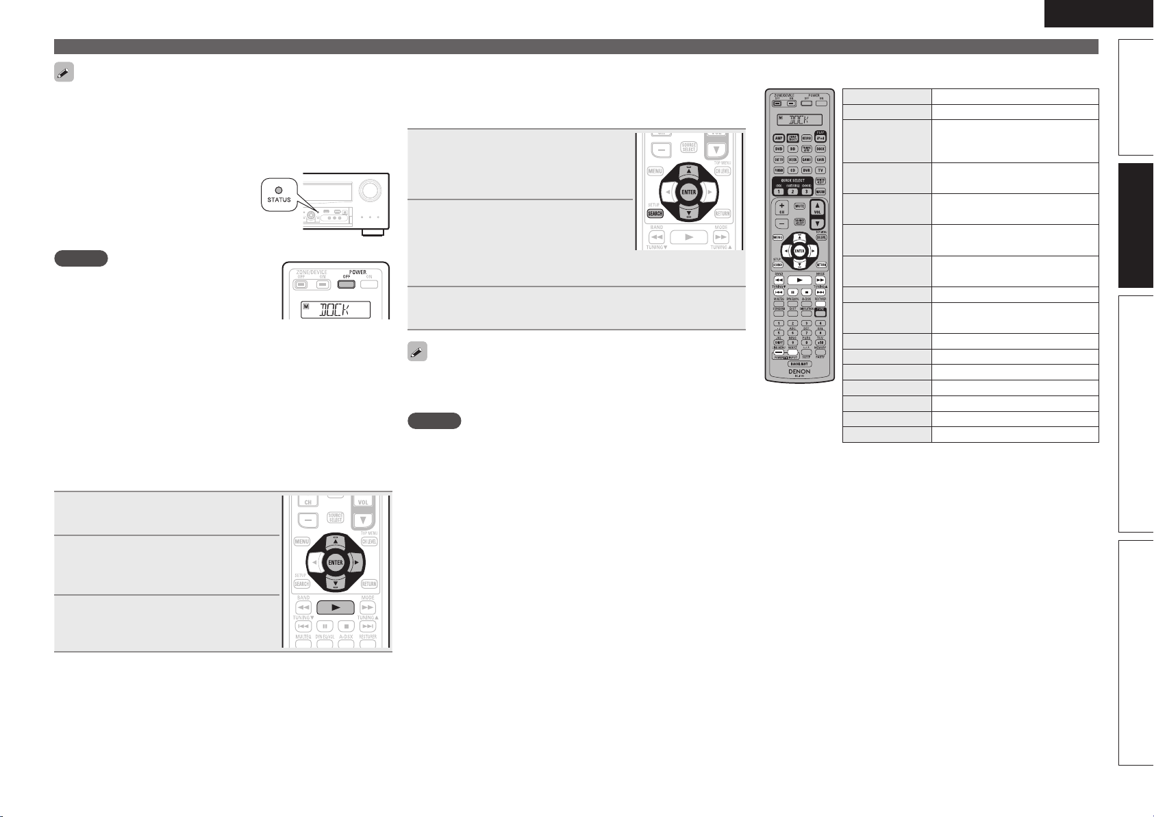
31
Simple version Advanced version Information
ENGLISH
Basic version
Playing an iPod
®
• You can specify the duration of the on-screen display to be displayed
(default: 30 sec) at menu “iPod” (vpage104). Press uio p to
return to the original screen.
• To play back compressed audio with extended bass or treble
reproduction, we recommend playback in RESTORER mode
(vpage92). The default setting is “Mode3”.
• In Browse mode, press
STATUS
during playback to check the title
name, artist name, and album name
on the display of this unit.
NOTE
• Press POWER OFF and set this unit’s power
to the standby mode before disconnecting
the iPod. Also switch the input source to
“DOCK” before disconnecting the iPod.
• Depending on the type of iPod and the software version, some
functions may not operate.
• Note that DENON will accept no responsibility whatsoever for any
problems arising with the data on an iPod when using this unit in
conjunction with the iPod.
n Viewing videos on an iPod
®
in the Browse
mode
When an iPod equipped with a video function is connected to a
DENON ASD-11R control dock for iPod, image files can be played
in the Browse mode.
1
Use ui to select “Videos”, then
press ENTER or p.
2
Use ui to select the search item
or folder, then press ENTER or
p.
3
Use ui to select the video le,
then press ENTER, p or 1.
Playback starts.
n Viewing photos and videos on an iPod
®
in the
Remote mode
This unit can play back on a TV screen photos and data stored on an
iPod equipped with a slide show or video function.
1
Press and hold SEARCH to set the
Remote mode.
“Remote iPod” or “Dock Remote“is
displayed on the display of this unit.
2
Watching the iPod’s screen,
use ui to select “Photos” or
“Videos”.
• Depending on the iPod model, it may be necessary to operate the
iPod unit directly.
3
Press ENTER until the image you want to view is
displayed.
“TV Out” at the iPod’s “Slide show Settings” or “Video Settings”
must be set to “On” in order to display the iPod’s photo data or videos
on the monitor. For details, see the iPod’s operating instructions.
NOTE
Video may not be output, depending on the combination of ASD-1R or
ASD-11R and iPod.
n iPod operation
Operation buttons Function
MENU Amp menu
uio p
Cursor operation /
Auto search (cue, ui) /
Manual search (Press and hold, ui)
ENTER
(Press and release)
Enter / Pause
ENTER
(Press and hold)
Stop
SEARCH
(Press and release)
Page search mode
z
SEARCH
(Press and hold)
Browse / Remote mode switching
RETURN Return
6 7
(Press and hold)
Manual search
(fast-reverse/fast-forward)
1
Playback / Pause
8 9
Auto search (cue)
3
Pause
2
Stop
RESTORER RESTORER
TV POWER TV power on/standby (Default : SONY)
TV INPUT Switch TV input (Default : SONY)
• Repeat playback (vpage85 “Repeat”)
• Shuffling playback (vpage85 “Shuffle”)
z When the menu screen is displayed, press
SEARCH, then press o (previous page) or p (next
page).
To cancel, press ui or SEARCH.
1.AVRA100E3_ENG_1st_0824.indd 31 2010/08/26 17:47:36
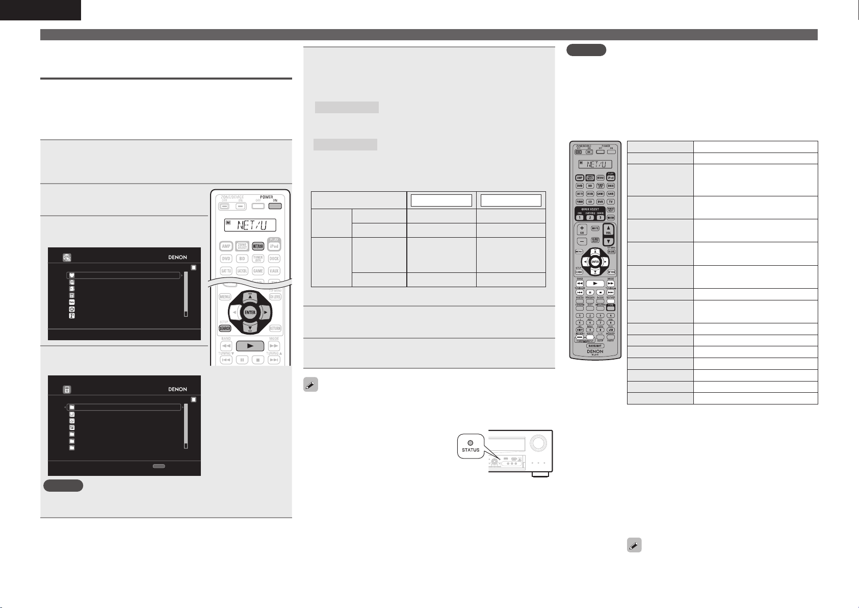
32
ENGLISH
w
Connect an iPod directly to the USB port
to play back
You can use the USB cable provided with the iPod
®
to connect the
iPod with the unit’s USB port and enjoy music stored on the iPod.
• This unit supports audio playback from the iPod (fi fth generation
or later), iPod nano, iPod classic, iPod touch and iPhone (it is not
compatible with iPod shuffl e).
1
Connect the iPod
®
to the USB port (vpage 22
“Connecting an iPod or USB memory device to the
USB port”).
2
Press POWER ON to turn on
power to the unit.
3
Press NET/USB to switch the
input source to “NET/USB”.
DENON:[AVR-A100]
Favorites
Internet Radio
Flickr
Napster
Pandora
Media Server
iPod
[1/8]
4
Use ui to select “iPod”, then
press ENTER or p.
iPod
Playlists
Artists
Podcasts
Genres
Composers
Albums
Songs
SEARCH
Search
[1/8]
NOTE
If the “iPod” is not displayed, the iPod may not be properly
connected. Reconnect it.
Playing an iPod
®
5
Press SEARCH and hold it down for 2 seconds or
more to select the display mode.
• There are two modes for displaying the contents recorded on the
iPod.
Browse mode
Display iPod information on the TV screen.
• English letters, numbers and certain symbols are displayed.
Incompatible characters are displayed as “.” (period).
Remote mode
Display iPod information on the iPod screen.
• “Remote iPod” is displayed on the display of this unit.
• The Remote mode is not supported on fi fth generation iPod or
fi rst generation iPod nano.
Display mode
Browse mode Remote mode
Playable
fi les
Music fi le
P P
Video fi le
z
Active
buttons
Remote
control unit
(This unit)
P P
iPod
®
P
zOnly the sound is played.
6
Use ui to select the item, then press ENTER or p
to select the le to be played.
7
Press ENTER, p or 1.
Playback starts.
• You can specify the duration of the on-screen display to be displayed
(default: 30 sec) at menu “iPod” (vpage104). Press uio p to
return to the original screen.
• To play back compressed audio with
extended bass or treble reproduction,
we recommend playback in
RESTORER mode (vpage 92). The
default setting is “Mode3”.
• In Browse mode, press
STATUS
during playback to check the title
name, artist name, and album name.
NOTE
• Depending on the type of iPod and the software version, some
functions may not operate.
• Note that DENON will accept no responsibility whatsoever for any
problems arising with the data on an iPod when using this unit in
conjunction with the iPod.
n iPod operation
Operation buttons Function
MENU Amp menu
uio p
Cursor operation /
Auto search (cue, ui) /
Manual search (Press and hold, ui)
ENTER
(Press and release)
Enter / Pause
ENTER
(Press and hold)
Stop
SEARCH
(Press and release)
Page search
z1
/ Character search
z2
SEARCH
(Press and hold)
Browse / Remote mode switching
RETURN Return
6 7
(Press and hold)
Manual search
(fast-reverse/fast-forward)
1
Playback / Pause
8 9
Auto search (cue)
3
Pause
2
Stop
RESTORER RESTORER
TV POWER TV power on/standby (Default : SONY)
TV INPUT Switch TV input (Default : SONY)
• Repeat playback (vpage85 “Repeat”)
• Random playback (vpage85 “Random”)
z1 When the menu screen is displayed, press
SEARCH, then press o (previous page) or p
(next page).
To cancel, press ui or SEARCH twice.
z2 When the menu screen is displayed, press
SEARCH twice, then press o p to select the
fi rst letter you want to search mode.
• If it is not possible to search the list, “unsorted
list.” is displayed.
To cancel, press ui or SEARCH.
If the list is not in alphabetical order, you may
not be able to perform a character search.
1.AVRA100E3_ENG_1st_0824.indd 32 2010/08/26 17:47:36
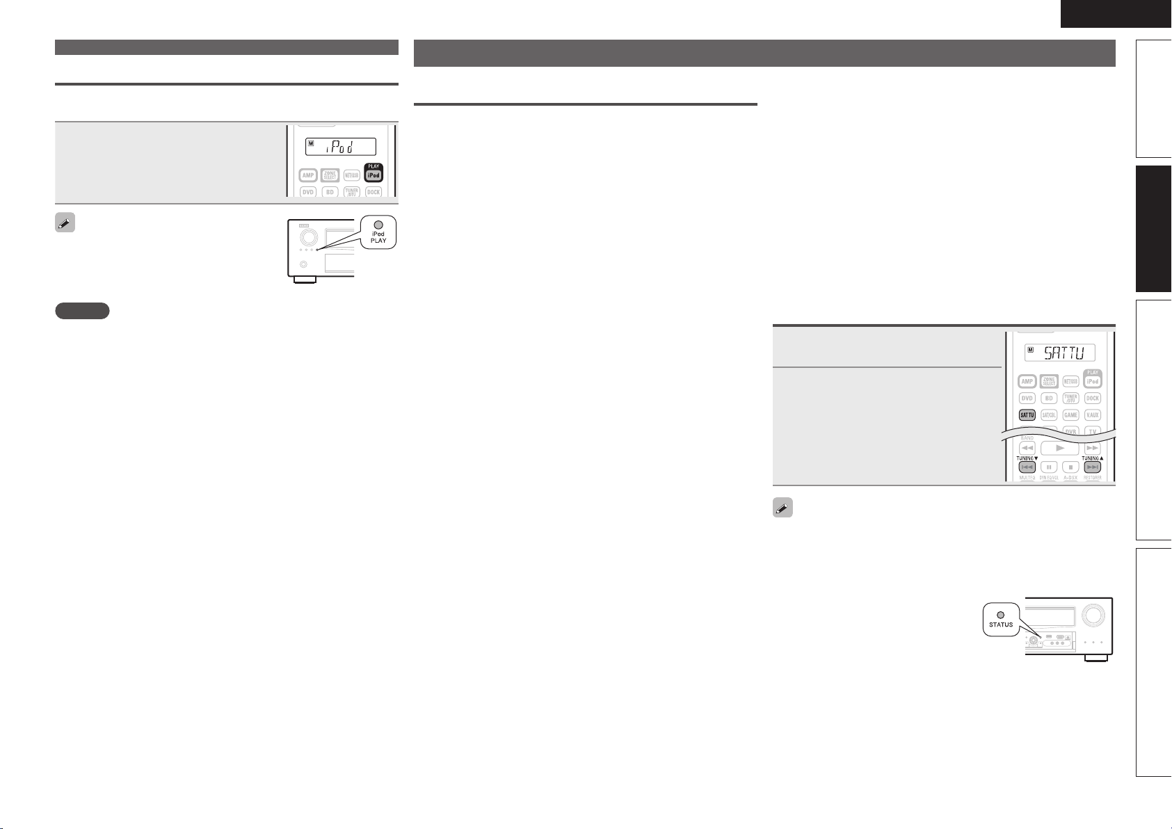
33
Simple version Advanced version Information
ENGLISH
Basic version
Tuning in radio stations
Important information
n About SIRIUS XM radio
To listen to Satellite Radio, you’ll need to connect either a SIRIUS
or XM Satellite Radio tuner (sold separately) to your satellite-ready
receiver. Satellite Radio is available to residents of the US (except
Alaska and Hawaii) and Canada.
Satellite Radio delivers a variety of commercial-free music from
categories ranging from Pop, Rock, Country, R&B, Dance, Jazz,
Classical and many more plus coverage of all the top professional
and college sports including play by play games from select
leagues and teams. Additional programming includes expert sports
talk, uncensored entertainment, comedy, family programming,
local traffic and weather and news from your most trusted sources.
Whether you purchase a SIRIUS or XM tuner, you’ll need to
activate and subscribe to begin enjoying the service. Easy to follow
installation and setup instructions are provided with the satellite
tuners. Whichever service you choose, there are a variety of
programming packages available, including the option of adding
“The Best of SIRIUS” programming to your XM tuner or “The Best
of XM” programming to your SIRIUS tuner, enabling you to enjoy
the most popular programming among both services. The “Best
of” packages are not available to SIRIUS or XM Canada subscribers
at this time.
Family friendly packages are also available to restrict channels
featuring content that may be inappropriate for children.
To subscribe to XM, U.S. customers should visit xmradio.com
or call 1-800-XMRADIO (1-800-967-2346); Canadian customers
should visit xmradio.ca or call XM Listener Care at 1-877-GETXMSR
(1-877-438- 9677).
To subscribe to SIRIUS, U.S. and Canadian customers can
call 1-888-539-SIRI (1-888-539-7474) or visit sirius.com (US) or
siriuscanada.ca (Canada).
n SIRIUS XM radio legal
SIRIUS, XM and all related marks and logos are trademarks of Sirius
XM Radio Inc. and its subsidiaries. All other marks and logos are the
property of their respective owners. All rights reserved. SIRIUS and
XM subscriptions sold separately. Taxes and a one-time activation
fee may apply. XM tuners and home docks or SIRIUS tuners (each
sold separately) are required to receive the SIRIUS or XM satellite
radio service. All programming and fees subject to change. It is
prohibited to copy, decompile, disassemble, reverse engineer,
hack, manipulate or otherwise make available any technology or
software incorporated in receivers compatible with the SIRIUS or
XM Satellite Radio Systems. Service not available in Alaska and
Hawaii.
n Using the HD Radio™ receiver
HD Radio stations offer higher sound quality than conventional
FM/ AM broadcasts. It is also possible to receive data services and
select broadcasts from among up to eight multicast programs.
HD Radio Technology provides higher quality sound than
conventional broadcasts and allows reception of data services.
• FM sounds as sensational as CDs
• AM sounds as rich as analog FM stereo
• A variety of “data services”, including text-based information,
song title, artist name, album name, genre, etc. can be received.
Furthermore, in addition to conventional broadcasts, with
HD Radio broadcasting it is possible to choose from up to 8
multicast programs.
For detailed information on HD Radio Technology, please go to
“www. hdradio.com”.
Listening to SIRIUS satellite radio
1
Press SAT TU to switch the input
source to “SIRIUS”.
2
Use TUNING d or TUNING f to
select the channel.
When the channel is tuned in, the name
of the song and artist are displayed.
• The channel switches continuously when TUNING d or TUNING f
is pressed and held.
• You can specify the duration of the on-screen display to be displayed
(default: 30 sec) at menu “TUNER” (vpage105). Press uio p to
return to the original screen.
• The song title, artist name, composer
name and reception level can be
checked by pressing
STATUS.
iPod play function
If iPod PLAY is pressed when a control dock for iPod or an iPod (USB)
is connected, the iPod starts playback.
Press iPod PLAY.
• Power of this unit is turned on.
• This unit’s input source switches to
“DOCK” or “NET/USB”.
• iPod playback starts.
If iPod PLAY on the main unit is pressed, the
same function as with the remote control unit
can be obtained.
NOTE
If both a control dock for iPod (“DOCK”) and an iPod (“NET/USB”)
are connected, playback with control dock for iPod (“DOCK”) takes
priority.
Playing an iPod
®
1.AVRA100E3_ENG_1st_0824.indd 33 2010/08/26 17:47:37
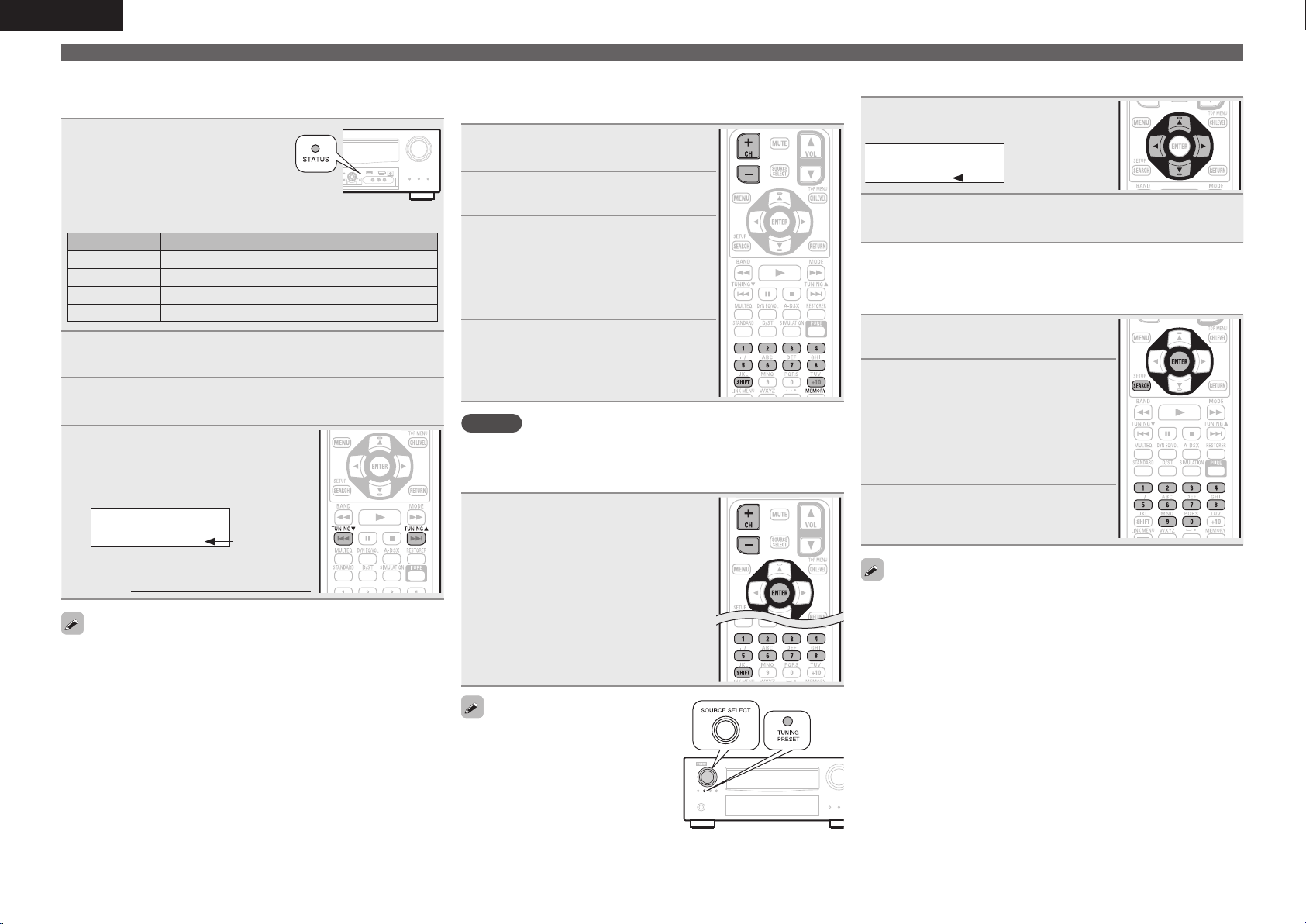
34
ENGLISH
Tuning in radio stations
n Checking the SIRIUS signal strength and radio
ID
1
Press STATUS until
“SIGNAL” appears on the
display.
The display will switch as shown
below, depending on the reception
conditions.
Display Status
EXCELLENT Signal strength is excellent
GOOD Signal strength is good
WEAK Signal strength is weak
NO SIGNAL No signal
2
Adjust the position of the antenna until “SIGNAL:
EXCELLENT” is shown on the display.
3
Press STATUS until the channel (example: “SR001”)
is displayed.
4
Press TUNING d or TUNING f
and select channel 0 (SR000).
Channel No. and Sirius ID are alternately
shown on the display.
S R0 0 0 S ir i u s I D
* ** * ** * ** * * *
Sirius ID
• Write your own SIRIUS ID for storage use.
Sirius ID :
The strength of both the SIRIUS satellite and terrestrial signals can be
checked “Antenna Aiming” (vpage81).
n Presetting radio channels (Preset memory)
Your favorite broadcast channels can be preset so that you can
tune them in easily. Up to 56 channels can be preset.
1
Tune in the broadcast channel
you want to preset.
2
Press MEMORY.
3
Press SHIFT to select the block
(A to G) in which to preset the
channel (1 to 8 per block), then
press CH +, CH – or 1 – 8 to select
the preset number.
4
Press MEMORY again to complete
the setting.
• To preset other stations, repeat steps 1 to
4.
NOTE
Preset channels are erased by overwriting them.
n Listening to preset channels
Press CH +, CH – to select the desired
preset channel, then press ENTER.
• Preset channels can also be selected by
pressing SHIFT (Block) and 1 – 8 (Channel).
You can also operate via the main unit.
In this case, perform the following
operations.
Press TUNING PRESET, then turn
SOURCE SELECT to select the preset
radio channel.
n Searching categories
1
Press o p.
S R0 0 1 H it s 1
C AT : Po p s
Channel category
2
Use o p to select the category, to use ui to select
the desired channel.
n Accessing SIRIUS satellite radio channels
directly
1
Press SEARCH.
2
Press 0 – 9 to input the channel.
Example: Accessing channel “SR123”:
Press 1, 2 and 3.
• If no button is pressed within several
seconds, the channel automatically
switches to the one whose number has
been input.
3
Press ENTER to set that channel.
Reception switches to the selected
channel.
• “UPDATING” is displayed while the encording code is being
updated.
• “SIRIUS UPDATING” is displayed when updating SIRIUS tuner
firmware.
• Refer to “Troubleshooting” – “SIRIUS Satellite Radio” (vpage136)
regarding other messages.
1.AVRA100E3_ENG_1st_0824.indd 34 2010/08/26 17:47:37
35
Simple version Advanced version Information
ENGLISH
Basic version
Tuning in radio stations
n Parental Lock
1
Tune to the channel you want to
lock.
2
Press ENTER for at least 3
seconds.
“Enter Lock Code” is displayed.
3
Enter the 4-digit lock code using
uio p or 0 – 9.
When you enter the correct code, the
corresponding channel is locked.
4
Press ENTER.
• Channels under Parental Lock cannot be tuned in by performing
channel up/down or by category search.
• Channels stored in preset memory can be tuned in by the preset
channel select operation, even if Parental Lock is applied.
• When a channel to which Parental Lock is applied is being played,
Parental Lock for that channel is cancelled by performing step 2.
• See “Edit Lock Code” (vpage 81) for the method of changing
Parental Lock Code.
• You can also set “Parental Lock” (vpage81) from the menu.
n SIRIUS operation
Operation buttons Function
CH +, – Preset channel selection
MENU Amp menu
uio p
Cursor operation / Category search
ENTER
(Press and hold)
To parental lock password check screen
SEARCH Direct search
RETURN Return
TUNING df
Channel selection
0 – 9
Preset channel selection (1 – 8) /
Direct channel tuning (0 – 9)
SHIFT Preset channel block selection
MEMORY Preset memory registration
TV POWER TV power on/standby (Default : SONY)
TV INPUT Switch TV input (Default : SONY)
Listening to HD Radio stations
1
Press TUNER/DTU to switch the
input source to “HD Radio”.
2
Press BAND to select “FM” or
“AM”.
FM
When listening to an FM broadcast.
AM
When listening to an AM broadcast.
AUTO
HD Radio
CH A
Now Playing
FM 87.50MHz
Tuning
CH+/
-
/
Preset
Band
MEMORY
Memory
SEARCH
Search
3
Tune in the desired broadcast station.
q To tune in automatically
(Auto tuning)
Press MODE to light the “HD-AUTO” or “AUTO” indicator on the
display, then use TUNING d or TUNING f to select the station
you want to hear.
• The
indicator lights on the display when an HD Radio station
is tuned in.
• When “HD-AUTO” (tuning mode) is selected, only HD Radio
stations are tuned in.
• If “AUTO” (tuning mode) is selected, both HD Radio and analog
stations are tuned in.
w To tune in manually (Manual tuning)
Press MODE to turn off the display’s “AUTO” indicator, then use
TUNING d or TUNING f to select the station you want to hear.
• If the desired station cannot be tuned in with auto tuning, tune it in
manually.
• When tuning in stations manually, press and hold TUNING d or
TUNING f to change frequencies continuously.
• The time (default : 30 sec) for which the menu are displayed can be
set at menu “TUNER” (vpage105). Press uio p to return to the
original screen.
1.AVRA100E3_ENG_1st_0824.indd 35 2010/08/26 17:47:38
36
ENGLISH
Tuning in radio stations
n Selecting audio programs
HD Radio Technology enables stations to broadcast multiple Audio
Program and data services on HD2 / HD3 / HD4 channels.
Press ui to select the audio
program.
If the station you are listening to has multiple
audio programs, “HD1” is indicated on the
display. If it only has one audio program,
“HD” is indicated.
n Presetting radio stations (Manual preset)
Your favorite broadcast stations can be preset so that you can tune
them in easily. Multicasts can also be preset. Up to 56 stations can
be preset.
• Stations can be preset automatically at “Auto Preset”
(vpage81). If “Auto Preset” is performed after performing “Manual
Preset”, the “Manual Preset” settings will be overwritten.
1
Tune in the broadcast station you
want to preset.
2
Press MEMORY.
3
Press SHIFT to select the block (A
to G) in which the channel (1 to 8
per a block) is to be preset, then
press CH +, CH – or 1 – 8 to select
the preset number.
4
Press MEMORY again to complete
the setting.
• To preset other stations, repeat steps 1 to
4.
Default settings
Block (A – G)
and
Channel (1 – 8)
Default Settings
A1 – A8
87.5 / 87.9 / 89.1 / 93.3 / 97.9 / 98.1 / 98.9 /
100.1 MHz
B1 – B8
101.9 / 102.7 / 107.9 / 90.1 / 90.1 / 90.1 / 90.1
/ 90.1 MHz
C1 – C8
530 / 600 / 930 / 1000 / 1120 / 1210 / 1400 /
1710 kHz
D1 – D8 90.1 MHz
E1 – E8 90.1 MHz
F1 – F8 90.1 MHz
G1 – G8 90.1 MHz
Specify a name for the preset broadcast station
(Preset Name) (vpage81)
n Listening to preset stations
1
Press SHIFT to select the memory
block (A to G).
2
Press CH +, CH – or 1 – 8 to select
the desired preset channel.
You can also operate via the main unit.
In this case, perform the following
operations.
Press TUNING PRESET, then turn
SOURCE SELECT to select the preset
radio station.
n Direct frequency tuning
You can enter the receiving frequency directly to tune in.
1
Press SEARCH.
2
Input frequencies using the 0 – 9.
• If o is pressed, the immediately preceding
input is cancelled.
3
When setting is completed, press
ENTER.
The preset frequency is tuned in.
n Check the HD Radio reception information
Press STATUS while an HD Radio
broadcast is being received.
The current reception information is
shown on the display.
q Normal
w Frequency / Signal strength
e Station name / Program and Program type
r Title name / Artist name
t Album name / Genre name
NOTE
If the station signal weakens while receiving a digital broadcast (while
and text is displayed), the mode automatically switches to the
analog reception mode (the reception frequency is displayed).
Because of this, the indicator and text may flicker if the station
signal level is weak and unstable.
1.AVRA100E3_ENG_1st_0824.indd 36 2010/08/26 17:47:39
37
Simple version Advanced version Information
ENGLISH
Basic version
Tuning in radio stations
Playing a network audio
Follow this procedure to play Internet radio stations or music or still
picture (JPEG) files stored on a computer.
Important information
n About the internet radio function
• Internet radio refers to radio broadcasts distributed over the
Internet.
Internet radio stations from around the world can be received.
• This unit is equipped with the following Internet radio functions:
• Stations can be selected by genre and location.
• Up to 56 Internet radio stations can be preset.
• Internet radio stations in MP3 and WMA (Windows Media
Audio) format can be listened to.
• Your favorite radio stations can be registered by accessing an
exclusive DENON Internet radio URL from a Web browser on
a computer.
• The function is managed for individual users, so you must provide
your MAC or e-mail address.
Exclusive URL: http://www.radiodenon.com
• The radio station database service may be suspended without
notice.
• This unit’s Internet radio station list is created using a radio
station database service (vTuner). This database service provides
a list edited and created for this unit.
n Media player
This function lets you play music files and playlists (m3u, wpl)
stored on a computer (media server) connected to this unit via a
network.
With this unit’s network audio playback function, connection to the
server is possible using one of the technologies below.
• Windows Media Player Network Sharing Service
• Windows Media DRM10
Album art function
When a WMA (Windows Media Audio), MP3 or MPEG-4 AAC file
includes album art data, the album art can be displayed while the
music files are playing.
For music files in WMA (Windows Media Audio) format, the album art
is only played when using Windows Media Player ver. 11.
Slide show function
Still picture (JPEG) files stored in folders on a media server can be
played as slide shows. The duration each picture is displayed can be
set.
This unit plays back image (JPEG) files in the orientation in which they
are stored in the folder.
GCompatible formatsH
Internet radio Media server
z1
WMA (Windows
Media Audio)
P P
MP3 (MPEG-1 Audio
Layer-3)
P P
WAV
P
MPEG-4 AAC
P
z2
FLAC (Free Lossless
Audio Codec)
P
JPEG
P
A server or server software compatible with distribution in the
corresponding formats is required to play music files via a network.
z1 Media server
• This unit is compatible with MP3 ID3-Tag (Ver. 2) standard.
• This unit can show the artwork that was embedded by using
MP3 ID3-Tag Ver. 2.3 or 2.4.
• This unit is compatible with WMA META tags.
• WAV format Quantization bit rate: 16 bits
• FLAC format Quantization bit rate: 16 or 24 bits
z2 Only files that are not protected by copyright can be played on
this unit.
Content downloaded from pay sites on the Internet are copyright
protected. Also, files encoded in WMA format when ripped from
a CD, etc. on a computer may be copyright protected, depending
on the computer’s settings.
n Tuner (HD Radio reception) operation
Operation buttons Function
CH +, – Preset channel selection
MENU Amp menu
uio p
Cursor operation /
Multicast switching (ui)
ENTER Enter
SEARCH Direct frequency tuning
RETURN Return
BAND FM/AM switching
MODE Switch search modes
TUNING df
Tuning (up/down)
0 – 9
Preset channel selection (1 – 8) /
Direct frequency tuning (0 – 9)
SHIFT Preset channel block selection
MEMORY Preset memory registration
TV POWER TV power on/standby (Default : SONY)
TV INPUT Switch TV input (Default : SONY)
1.AVRA100E3_ENG_1st_0824.indd 37 2010/08/26 17:47:39
38
ENGLISH
GCompatible formatsH
Sampling
frequency
Bit rate Extension
WMA (Windows
Media Audio)
32/44.1/48 kHz 48 – 192 kbps .wma
MP3 (MPEG-1
Audio Layer-3)
32/44.1/48 kHz 32 – 320 kbps .mp3
WAV 32/44.1/48 kHz – .wav
MPEG-4 AAC 32/44.1/48 kHz 16 – 320 kbps
.aac/
.m4a/
.mp4
FLAC (Free
Lossless Audio
Codec)
32/44.1/48/
88.2/96 kHz
– .flac
n About Flickr
Flickr is an online photograph sharing service that started in 2004.
You can use the this unit to view photographs that have been made
public by Flickr users. You do not need an account to use Flickr.
To view photographs that you recorded yourself, you need an
account in order to upload these photographs to the Flickr server.
For details, see the Flickr homepage.
http://www.flickr.com/
n About Napster
Napster is a monthly subscription music distribution service
provided by Napster LLC. This service allows users to download
and play pieces of music they want to hear on this unit. Before
you can use Napster, you will need to visit the Napster website on
your PC to create an account and register as a member. For details,
access the following site:
http://www.napster.com/choose/index_default.html
n About Pandora
Pandora is an automated music recommendation and Internet
radio service created by the Music Genome Project.
When you first listen to Pandora, it is necessary to subscribe to a
Pandora account at the Pandora homepage by your PC and register
this machine. See the Pandora homepage for details.
http://www.pandora.com/denon
Playing a network audio
n About Rhapsody
Rhapsody is a paid music broadcast service of RealNetworks.
When you first listen to Rhapsody, it is necessary to subscribe to
a Rhapsody account at the Rhapsody homepage by your PC and
register this machine. See the Rhapsody homepage for details.
http://www.rhapsody.com/denon
Listening to internet radio
1
Prepare for playback.
q Check the network environment, then turn on this unit’s
power (vpage26 “Connecting to a home network (LAN)”).
w If settings are required, make the “Network Connecting”
(vpage101).
2
Press NET/USB to switch the
input source to “NET/USB”.
3
Press ui to select “Internet
Radio”, then press ENTER or p.
• Selecting
in the “SOURCE SELECT”
menu, lets you directly select “Internet
Radio”.
4
Press ui to select the item you
want to play, then press ENTER
or p.
5
Repeat step 4 until the station list is displayed.
The station list is displayed.
6
Press ui to select the station, then press ENTER or
p.
Playback starts once buffering reaches “100%”.
• There are many Internet radio stations on the Internet, and the
quality of the programs they broadcast as well as the bit rate of the
tracks varies widely.
Generally, the higher the bit rate, the higher the sound quality, but
depending on the communication lines and server traffic, the music
or audio signals being streamed may be interrupted. Inversely, lower
bit rates mean a lower sound quality but less tendency for the sound
to be interrupted.
• “Server Full” or “Connection Down” is displayed if the station is
busy or not broadcasting.
• On this unit, folder and file names can be displayed as titles. Any
characters that cannot be displayed are replaced with “.” (period).
• To play back compressed audio with extended bass or treble
reproduction, we recommend playback in RESTORER mode
(vpage92). The default setting is “Mode3”.
• You can specify the duration of the on-screen display to be displayed
(default: 30 sec) at menu “NET/USB” (vpage104). Press uio p
to return to the original screen.
• When
STATUS is pressed, the display
can be switched between the title
name and radio station name.
n Recently played internet radio stations
Recently played internet radio stations can be selected from
“Recently Played”.
Up to 20 stations stored in “Recently Played”.
1
Press ui to select “Recently
Played”, then press ENTER or p.
2
Press ui to select the item you
want to play, then press ENTER or
p.
1.AVRA100E3_ENG_1st_0824.indd 38 2010/08/26 17:47:39
39
Simple version Advanced version Information
ENGLISH
Basic version
Playing a network audio
n Searching stations by keyword
(Alphabetic strings)
1
Press ui to select “Search by Keyword”, then press
ENTER or p.
Enter Station
Search by Keyword
SubmitInput
SEARCH
Keyboard
CH+
Insert
CH-
Delete
RETURN
Cancel
0-9
• For character input, see page 78.
2
Input the characters, then press ENTER.
n Presetting internet radio stations
Preset Internet radio stations can be selected directly.
1
While the Internet radio station
you want to preset is playing,
press MEMORY.
2
Press ui to select “Preset”,
then press ENTER.
3
Press SHIFT, then press CH +,
CH – or 1 – 8 to select the desired
preset number.
4
Press MEMORY again to complete
the setting.
The Internet radio station is now preset.
NOTE
If registered at a number that has already been preset, the previously
registered setting is cleared.
n Listening to preset internet radio stations
After pressing SHIFT, press CH +,
CH – or 1 – 8 to select the registered
preset number.
This unit automatically connects to the
Internet and playback begins.
n Registering internet radio stations as your
favorites
Favorites are listed at the top of the menu screen, so when a
station is registered as a favorite it can be tuned in easily.
1
Press MEMORY while the Internet
radio station you want to register
is playing.
2
Press ui to select “Favorites”,
then press ENTER.
3
Press o to select “Add”.
The Internet radio station is registered.
• If you do not want to register the station,
press p.
n Listening to internet radio stations registered in
your favorites
1
Press SOURCE SELECT to display the SOURCE
SELECT menu, then select
(vpage 28).
2
Press ui to select the Internet
radio station, then press ENTER
or p.
This unit automatically connects to the
Internet and playback begins.
n Clearing internet radio stations from your
favorites
1
Press SOURCE SELECT to display
the SOURCE SELECT menu,
then select
(vpage 28).
2
Press ui to select the Internet
radio station you want to clear,
then press MEMORY.
3
Press o to select “Remove”.
The selected Internet radio station is
cleared.
• To cancel the operation without clearing the
station, press p.
1.AVRA100E3_ENG_1st_0824.indd 39 2010/08/26 17:47:40
40
ENGLISH
n Internet radio operation
Operation buttons Function
CH +, – Preset channel selection
MENU Amp menu
uio p
Cursor operation
ENTER
(Press and release)
Enter
ENTER
(Press and hold)
Stop
SEARCH Page search
z1
/ Character search
z2
RETURN Return
2
Stop
RESTORER RESTORER
1 – 8 Preset channel selection
SHIFT Preset channel block selection
MEMORY Favorites / Preset memory registration
TV POWER TV power on/standby (Default : SONY)
TV INPUT Switch TV input (Default : SONY)
z1 When the menu screen is displayed, press
SEARCH, then press o (previous page) or p
(next page).
To cancel, press ui or SEARCH twice.
z2 When the menu screen is displayed, press
SEARCH twice, then press o p to select the
first letter you want to search mode.
• If it is not possible to search the list, “unsorted
list.” is displayed.
To cancel, press ui or SEARCH.
If the list is not in alphabetical order, you may
not be able to perform a character search.
Playing a network audio
Playing files stored on a computer
Use this procedure to play music files, image files or playlists.
1
Prepare for playback.
q Check the network environment, then turn on this unit’s
power (vpage26 “Connecting to a home network (LAN)”).
w If settings are required, make the “Network Connecting”
(vpage101).
e Prepare the computer (vComputer’s operating
instructions).
2
Press SOURCE SELECT to display
the SOURCE SELECT menu,
then select
(vpage 28).
3
Press ui to select the server
including the le to be played,
then press ENTER or p.
4
Press ui to select the search item or folder, then
press ENTER or p.
5
Repeat step 4 until the le is displayed.
6
Press ui to select the le, then press ENTER or p.
Playback starts once buffering reaches “100%”.
• Connections to the required system and specific settings must be
made in order to play music files (vpage26).
• Before starting, you must launch the computer’s server software
and set the files as server contents. For details, see the operating
instructions of your server software.
• Depending on the size of the still picture (JPEG) file, some time may
be required for the file to be displayed.
• The order in which the tracks/files are displayed depends on
the server specifications. If the tracks/ files are not displayed in
alphabetical order due to the server specifications, searching by the
first letter may not work properly.
• WMA Lossless files can be played when using a server supporting
transcoding, such as Windows Media Player Ver. 11.
• To play back compressed audio with extended bass or treble
reproduction, we recommend playback in RESTORER mode
(vpage92). The default setting is “Mode3”.
• You can specify the duration of the on-screen display to be displayed
(default: 30 sec) at menu “NET/USB” (vpage104). Press uio p
to return to the original screen.
• Use
STATUS to switch between
displaying the title name, artist name
or album name.
n Playing files that have been preset or registered
in your favorites
Files can be preset, registered in your favorites and played using
the same operations as for Internet radio stations (vpage39).
NOTE
• Presettings are erased by overwriting them.
• When the operations described below is performed, the media
server’s database is updated and it may no longer be possible to
play preset or favorite music files.
• When you quit the media server and then restart it.
• When music files are deleted or added on the media server.
• When using an ESCIENT server, place “ESCIENT” before the server
name.
1.AVRA100E3_ENG_1st_0824.indd 40 2010/08/26 17:47:41
41
Simple version Advanced version Information
ENGLISH
Basic version
Playing a network audio
n Media server operation
Operation buttons Function
CH +, – Preset channel selection
MENU Amp menu
uio p
Cursor operation /
Auto search (cue, ui)
ENTER
(Press and release)
Enter / Pause
ENTER
(Press and hold)
Stop
SEARCH Page search
z1
/ Character search
z2
RETURN Return
1
Playback / Pause
8 9
Auto search (cue)
3
Pause
2
Stop
RESTORER RESTORER
1 – 8 Preset channel selection
SHIFT Preset channel block selection
MEMORY Favorites / Preset memory registration
TV POWER TV power on/standby (Default : SONY)
TV INPUT Switch TV input (Default : SONY)
• Repeat playback (vpage85 “Repeat”)
• Random playback (vpage85 “Random”)
• Slide show playback (vpage85 “Slide Show”)
z1 When the menu screen is displayed, press
SEARCH, then press o (previous page) or p
(next page).
To cancel, press ui or SEARCH twice.
z2 When the menu screen is displayed, press
SEARCH twice, then press o p to select the
fi rst letter you want to search mode.
• If it is not possible to search the list, “unsorted
list.” is displayed.
To cancel, press ui or SEARCH.
If the list is not in alphabetical order, you may
not be able to perform a character search.
Viewing photographs on the Flickr site
You can view photographs shared by particular users, or all of the
photographs shared on Flickr.
n Viewing photographs shared by particular users
1
Prepare for playback.
q Check the network environment, then turn on this unit’s
power (vpage26 “Connecting to a home network (LAN)”).
w If settings are required, make the “Network Connecting”
(vpage101).
2
Press SOURCE SELECT to display
the SOURCE SELECT menu,
then select
(vpage 28).
3
Use ui to select “Add Flickr
Contact”, then press ENTER or
p.
Flickr
Add Flickr Contact
All Content
[1/2]
4
Enter “Username”.
• For character input, see page 78.
5
After inputting the “Username”, then press ENTER.
The “User Name” entered in step 4 is displayed.
• If the Username you typed in cannot be found, “The Flickr Contact
you entered could not be found” appears. Check and type in the
correct Username.
6
Press ui to select the folder, and then press ENTER
or p.
Favorites
Displays the favorite photographs of the specifi ed
user.
Photostream
Displays a list of shared photographs.
PhotoSets
Displays the folder (photograph album) list.
Contacts
Displays a Username registered for Flickr Contact by
a specifi ed user.
Remove this
Contact
Deletes a user from Flickr Contact.
7
Press ui to select the le, and then press ENTER
or p.
The selected fi le is displayed.
1.AVRA100E3_ENG_1st_0824.indd 41 2010/08/26 17:47:41
42
ENGLISH
Playing a network audio
n Viewing all photographs on Flickr
1
Prepare for playback.
q Check the network environment, then turn on this unit’s
power (vpage26 “Connecting to a home network (LAN)”).
w If settings are required, make the “Network Connecting”
(vpage101).
2
Press SOURCE SELECT to display
the SOURCE SELECT menu,
then select
(vpage 28).
3
Use ui to select “All Content”,
then press ENTER or p.
Flickr
Add Flickr Contact
All Content
[1/2]
4
Press ui to select the folder, and then press ENTER
or p.
Interestingness
Displays photographs that are popular from the
number of user comments or number of times they
are added as favorites.
Recent
Displays the most recently added photographs.
Search by text
Search for photographs by keyword.
5
Press ui to select the le, and then press ENTER
or p.
The selected fi le is displayed.
NOTE
Depending on the fi le format, some photographs cannot be viewed.
n Flickr operation
Operation buttons Function
CH +, – Preset channel selection
MENU Amp menu
uio p
Cursor operation /
Auto search (cue, ui)
ENTER
(Press and release)
Enter
ENTER
(Press and hold)
Stop
SEARCH Page Search
z
RETURN Return
2
Stop
1 – 8 Preset channel selection
SHIFT Preset channel block selection
TV POWER TV power on/standby (Default : SONY)
TV INPUT Switch TV input (Default : SONY)
• Slide show playback (vpage85 “Slide Show”)
z When the menu screen is displayed, press
SEARCH, then press o (previous page) or p (next
page).
To cancel, press ui or SEARCH.
Listening to Napster
1
Prepare for playback.
q Check the network environment, then turn on this unit’s
power (vpage26 “Connecting to a home network (LAN)”).
w If settings are required, make the “Network Connecting”
(vpage101).
2
Press SOURCE SELECT to display
the SOURCE SELECT menu,
then select
(vpage 28).
3
Use ui p to input “Username”
and “Password”.
Napster Account
OK
Enter Username
Username
Password
RETURN
Cancel
• For character input, see page 78.
4
After inputting the “Username” and “Password”,
select “OK”, then press ENTER.
If the “Username” and “Password” match, the top menu for
Napster is displayed.
NOTE
• The password should be no longer than 99 characters.
• Press RETURN to cancel the input. When “Cancel input?” is
displayed, select “Yes”, then press ENTER.
1.AVRA100E3_ENG_1st_0824.indd 42 2010/08/26 17:47:42
43
Simple version Advanced version Information
ENGLISH
Basic version
n Searching from Napster menu
1
Use ui to select search item or
folder, then press ENTER or p.
2
Repeat step 1 until the track is
displayed.
3
Use ui to select the track item, then press ENTER
or p.
n Entering a character search for the track you
want to listen to
1
Press SEARCH.
My Napster Library
Top 100s
New Releases
Radio
Napster Playlists
E
Staff Picks
[1/8]
Napster
Search by Artist
Search by Album
Search by Track
SEARCH
Search
• You can search by artist name, album name or track name.
2
Use ui to select the search item, then press ENTER.
The search display appears.
Enter Artist Name
Search by Artist
SubmitInput
SEARCH
0-9
Keyboard
CH+
Insert
CH-
Delete
RETURN
Cancel
• For character input, see page 78.
3
Input the characters, then press ENTER.
n Registering tracks in my Napster library
1
Press p while the track you wish
to register is playing.
2
Select “Add to my library”, then
press ENTER or p.
The track is entered in the Library.
Listening to tracks registered in my Napster library
1
Use ui to select “My Napster
Library”, then press ENTER or
p.
2
Use ui to select the information
or track, then press ENTER.
• To play back compressed audio with extended bass or treble
reproduction, we recommend playback in RESTORER mode
(vpage92). The default setting is “Mode3”.
• You can specify the duration of the on-screen display to be displayed
(default: 30 sec) at menu “NET/USB” (vpage104). Press uio p
to return to the original screen.
• Use
STATUS to switch between
displaying the title name, artist name
or album name.
Playing a network audio
n Napster operation
Operation buttons Function
CH +, – Preset channel selection
MENU Amp menu
uio p
Cursor operation /
Auto search (cue, ui)
ENTER
(Press and release)
Enter
ENTER
(Press and hold)
Stop
SEARCH Search menu / Page search
z
RETURN Return
1
Playback
8 9
Auto search (cue)
2
Stop
RESTORER RESTORER
1 – 8 Preset channel selection
SHIFT Preset channel block selection
TV POWER TV power on/standby (Default : SONY)
TV INPUT Switch TV input (Default : SONY)
• Repeat playback (vpage85 “Repeat”)
• Random playback (vpage85 “Random”)
z When the menu screen is displayed, press
SEARCH twice, then press o (previous page) or
p (next page).
To cancel, press ui or SEARCH.
1.AVRA100E3_ENG_1st_0824.indd 43 2010/08/26 17:47:42
44
ENGLISH
Playing a network audio
Listening to Pandora
1
Prepare for playback.
q Check the network environment, then turn on this unit’s
power (vpage26 “Connecting to a home network (LAN)”).
w If settings are required, make the “Network Connecting”
(vpage101).
2
Press SOURCE SELECT to display
the SOURCE SELECT menu,
then select
(vpage 28).
Pandora Account
I have a Pandora account
I am new to Pandora
Enter
RETURN
Cancel
• If you do not have a Pandora account, press i to select “I am
new to Pandora”. The URL of Pandora and activation code are
displayed. Access the Pandora web page from your PC and register
the displayed activation code and account information. Then press
ENTER.
Pandora Account
I have a Pandora account
Please go to
http://www.pandora.com/denon
and follow the instructions there to create
a new account.
Your activation code is : 4DA2C67B
I am new to Pandora
Continue
RETURN
Cancel
3
If you have a Pandora account, press ui to select
“I have a Pandora account”, then press ENTER or p.
Pandora Account
OK
Enter Email address
Email address
Password
RETURN
Cancel
4
Input “Email address” and “Password”.
• For character input, see page 78.
5
After inputting the “Email address” and “Password”,
select “OK”, then press ENTER.
If the “Email address” and “Password” match, the top menu for
Pandora is displayed.
NOTE
Press RETURN to cancel the input. When “Cancel input?” is displayed,
select “Yes”, then press ENTER.
n Creating an original radio station
You can create up to 100 original radio stations.
1
Use ui to select “New Station”,
then press ENTER or p.
My Station
New Station
Quick Mix
D&M1 Radio
[1/3]
RETURN
Sign out
Exit
2
Input a “Track Name” or “Artist Name”, then press
ENTER.
• For character input, see page 78.
3
Use ui to select “Search by artist” or “Search by
track”, then press ENTER.
You can search and display a list by track or artist.
4
Press ui, select a le (e.g. D&M2) from the list,
and press ENTER or p.
Selected fi le is played back.
“Radio” is added to the end of a fi lename, and your original
radio station is created (e.g. D&M2 Radio).
My Station
New Station
Quick Mix
D&M1 Radio
D&M2 Radio
[1/4]
RETURN
Sign out
Exit
1.AVRA100E3_ENG_1st_0824.indd 44 2010/08/26 17:47:43
45
Simple version Advanced version Information
ENGLISH
Basic version
Playing a network audio
n Listening to a created radio station
Listening to a created radio station (e.g. D&M2
Radio)
By specifying your favorite track or artist name, music that has a
similar rhythm or sound is chosen and streamed.
Press ui and select the radio station
(“D&M2 Radio”) that you want to
listen to, and press ENTER or p.
In Pandora, you can search for the track name
or artist name using “D&M2” as a keyword.
When the search is complete, tracks that
have a similar rhythm or sound are streamed.
D&M2 Radio
00:15
100%
Song
Artist
Album
Pause Skip Select
Menu
Now Playing
MP3 128kbps
Listening to created radio stations at random
Use ui to select “Quick Mix”, then
press ENTER or p.
Created radio stations are selected at
random, and tracks are streamed.
n Arranging tracks within radio stations
You can sort tracks by operating the Pandora menu screen while
a track is playing.
Press p while a track is playing.
The Pandora menu screen is displayed.
Menu
I like this track
I don’t like this track
Bookmark this track
I’m tired of this track
Delete this station
Why is this track playing?
Create station
[1/7]
I like this track
• Press when you like the track that is being played.
• It will return to the Play Screen. And
(Thumbs
up) icon is displayed. (The icon is not displayed on
the next track.)
I don’t like
this track
• Press when you don’t like the track that is being
played.
• It will return to the Play Screen. And
(Thumbs
down) icon is displayed. (The icon is not displayed
on the next track.)
Why is this
track playing?
• Displays the reason why Pandora selected this
track.
Create station
• Creates a Station for the Track or Artist being
played.
Bookmark
this track
• Bookmarks the track currently being played.
• You can check on a computer or iPhone etc.
• For details, see the Pandora web page.
I’m tired of
this track
• Press when you don’t like the track that is being
played.
• The track will not be played for 1 month.
Delete this
station
• Press when you want to delete the station that is
being played.
NOTE
• You can Skip up to 6 Tracks that are being played back within 1 hour.
• You can create up to 100 New Stations (radio stations).
n Sign out
Disassociate this unit from your Pandora account.
1
While the Pandora top menu is
displayed, press RETURN.
My Station
New Station
Quick Mix
D&M1 Radio
D&M2 Radio
[1/4]
RETURN
Sign out
Exit
2
When the popup menu appears, press o p to select
“Yes”, then press ENTER.
n Pandora operation
Operation buttons Function
MENU Amp menu
uio p
Cursor operation /
Auto search (cue, i)
ENTER
(Press and release)
Enter / Pause
ENTER
(Press and hold)
Stop
SEARCH Page search
z
RETURN Return
1
Playback
9
Auto search (cue)
3
Pause
2
Stop
RESTORER RESTORER
TV POWER TV power on/standby (Default : SONY)
TV INPUT Switch TV input (Default : SONY)
z When the menu screen is displayed, press
SEARCH, then press o (previous page) or p (next
page).
To cancel, press ui or SEARCH.
1.AVRA100E3_ENG_1st_0824.indd 45 2010/08/26 17:47:44
46
ENGLISH
Playing a network audio
Listening to Rhapsody
1
Prepare for playback.
q Check the network environment, then turn on this unit’s
power (vpage26 “Connecting to a home network (LAN)”).
w If settings are required, make the “Network Connecting”
(vpage101).
2
Press SOURCE SELECT to display
the SOURCE SELECT menu,
then select
(vpage 28).
3
Use ui to select “Sign in to
your account”, then press ENTER
or p.
Rhapsody
Start a 30-day trial
Sign in to your account
Enter
RETURN
Cancel
4
Input Username and Password.
Rhapsody account sign in
OK
Enter Username
Username
Password
RETURN
Cancel
• For character input, see page 78.
5
After inputting the “Username” and “Password”,
select “OK”, then press ENTER.
If the “Username” and “Password” match, the top menu for
Rhapsody is displayed.
NOTE
• The password should be no longer than 99 characters.
• Press RETURN to cancel the input. When “Cancel input?” is
displayed, select “Yes”, then press ENTER.
n Select the search mode
Rhapsody
Rhapsody Music Guide
Search
Rhapsody Channels
My Library
[1/4]
q
w
e
r
q Search from Rhapsody latest information
1
Use ui to select “Rhapsody
Music Guide”, then press ENTER
or p.
2
Press ui to select the
information for track selection,
then press ENTER or p.
• For character input, see page 78.
3
Repeat step 2 until the track is displayed.
4
Use ui to select the track, then press ENTER or p.
w Enter a character search for the track you want
to listen to
1
Use ui to select “Search”, then
press ENTER or p.
2
Use ui to select the search item,
then press ENTER or p.
The search display appears.
• You can search by artist name, album name,
track name or keyword.
3
Enter the characters, then press ENTER.
e Search from the Rhapsody internet radio station
1
Use ui to select “Rhapsody
Channels”, then press ENTER or
p.
2
Repeat step 1 until the radio
station is displayed.
3
Use ui to select radio station, then press ENTER
or p.
The search display appears.
r Listening to tracks registered in my library
1
Use ui to select “My Library”,
then press ENTER or p.
2
Repeat step 1 until the track is
displayed.
3
Use ui to select the information or track, then
press ENTER or p.
After selecting, the information is displayed
1.AVRA100E3_ENG_1st_0824.indd 46 2010/08/26 17:47:45
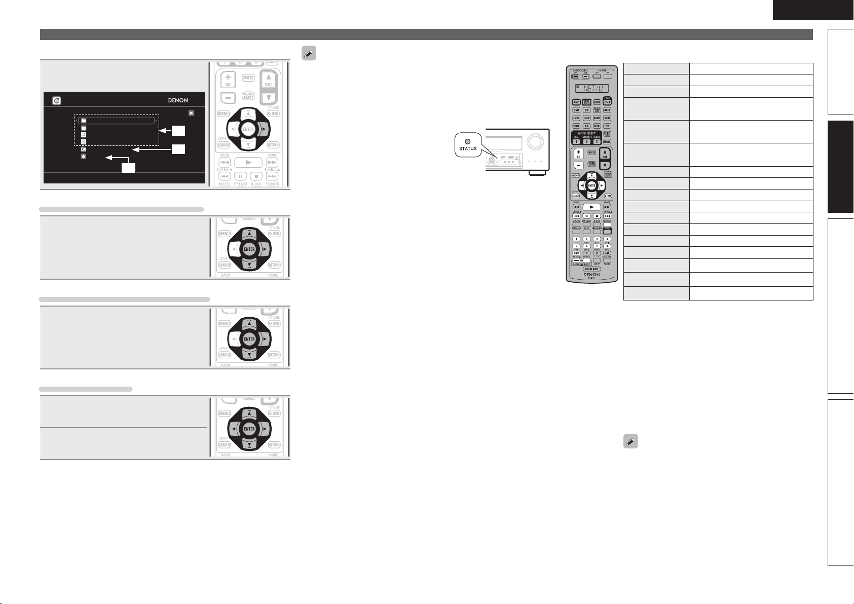
47
Simple version Advanced version Information
ENGLISH
Basic version
Playing a network audio
n Track menu
Press p during playback to display
the track menu.
Rhapsody
Jump to artist
Jump to album
Similar artists
Similar albums
Add to my library
Rating
[1/6]
q
w
e
q Search from the similar music
Use ui to select the search item,
then press ENTER or p.
w Registering tracks in my library
Use ui to select “Add to my
library”, then press ENTER or p.
The track is entered in the library.
e Rating function
1
Use ui to select “Rating”, then
press ENTER or p.
2
Use o p to select the rating, then
press ENTER.
• To play back compressed audio with extended bass or treble
reproduction, we recommend playback in RESTORER mode
(vpage92). The default setting is “Mode3”.
• You can specify the duration of the on-screen display to be displayed
(default: 30 sec) at menu “NET/USB” (vpage104). Press uio p
to return to the original screen.
• Use
STATUS to switch between
displaying the title name, artist name
or album name.
n Rhapsody operation
Operation buttons Function
CH +, – Preset channel selection
MENU Amp menu
uio p
Cursor operation /
Auto search (cue, ui)
ENTER
(Press and release)
Enter / Pause
ENTER
(Press and hold)
Stop
SEARCH Page search
z1
/ Character search
z2
RETURN Return
1
Playback / Pause
8 9
Auto search (cue)
3
Pause
2
Stop
RESTORER RESTORER
1 – 8 Preset channel selection
SHIFT Preset channel block selection
TV POWER TV power on/standby (Default : SONY)
TV INPUT Switch TV input (Default : SONY)
• Repeat playback (vpage85 “Repeat”)
• Random playback (vpage85 “Random”)
z1 When the menu screen is displayed, press
SEARCH, then press o (previous page) or p
(next page).
To cancel, press ui or SEARCH twice.
z2 When the menu screen is displayed, press
SEARCH twice, then press o p to select the
fi rst letter you want to search mode.
• If it is not possible to search the list, “unsorted
list.” is displayed.
To cancel, press ui or SEARCH.
If the list is not in alphabetical order, you may
not be able to perform a character search.
1.AVRA100E3_ENG_1st_0824.indd 47 2010/08/26 17:47:45
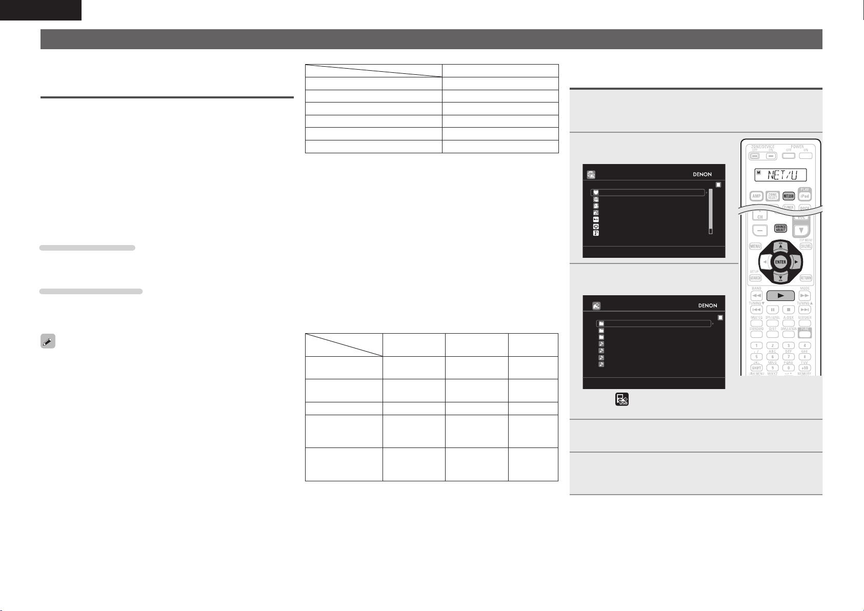
48
ENGLISH
Playing a USB memory device
Playing back music or still picture (JPEG) fi les recorded on a USB
memory device.
Important information
n USB memory devices
A USB memory device can be connected to the USB port of this
unit to play music and still picture (JPEG) fi les stored on the USB
memory device.
Also, fi les stored on an iPod can be played when the iPod is
connected directly to the USB port of this unit. See “Connect an
iPod directly to the USB port to play back” (vpage32).
• Only USB memory devices conforming to mass storage class and
MTP (Media Transfer Protocol) standards can be played on this
unit.
• This unit is compatible with USB memory devices in “FAT16” or
“FAT32” format.
Album art function
When an MP3 music fi le includes album art data, the album art can be
displayed while playing the fi le.
Slide show function
Still picture (JPEG) fi les stored on USB memory devices can be played
as slide shows.
The duration each picture is displayed can be set (vpage85).
This unit plays back image (JPEG) fi les in the orientation in which they
are stored in the folder.
GCompatible formatsH
USB memory devices
z1
WMA (Windows Media Audio)
P
z2
MP3 (MPEG-1 Audio Layer-3)
P
WAV
P
MPEG-4 AAC
P
z3
FLAC (Free Lossless Audio Codec)
P
JPEG
P
z1 USB
• This unit is compatible with MP3 ID3-Tag (Ver. 2) standard.
• This unit can show the artwork that was embedded by using
MP3 ID3-Tag Ver. 2.3 or 2.4.
• This unit is compatible with WMA META tags.
• WAV format Quantization bit rate: 16 bits
• FLAC format Quantization bit rate: 16 or 24 bits
z2 Copyright-protected fi les can be played on certain portable
players compatible with MTP.
z3 Only fi les that are not protected by copyright can be played on
this unit.
Content downloaded from pay sites on the Internet are copyright
protected. Also, fi les encoded in WMA format when ripped from
a CD, etc. on a computer may be copyright protected, depending
on the computer’s settings.
GCompatible formatsH
Sampling
frequency
Bit rate Extension
WMA (Windows
Media Audio)
32/44.1/48 kHz 48 – 192 kbps .wma
MP3 (MPEG-1
Audio Layer-3)
32/44.1/48 kHz 32 – 320 kbps .mp3
WAV 32/44.1/48 kHz – .wav
MPEG-4 AAC 32/44.1/48 kHz 16 – 320 kbps
.aac/
.m4a/
.mp4
FLAC (Free
Lossless Audio
Codec)
32/44.1/48/
88.2/96 kHz
– .fl ac
Playing fi les stored on USB memory
devices
1
Connect the USB memory device to the USB port
(vpage 22 “Connecting an iPod or USB memory
device to the USB port”).
2
Press NET/USB to switch the
input source to “NET/USB”.
DENON:[AVR-A100]
Favorites
Internet Radio
Flickr
Napster
Pandora
Media Server
USB
[1/8]
3
Use ui to select “USB”, then
press ENTER or p.
USB
D&M1
D&M2
Music2.mp3
Music3.m4a
Music4.m4a
D&M3
Music1.mp4
[1/7]
• Selecting in the “SOURCE SELECT” menu, lets you directly
select “USB”.
4
Press ui to select the search item or folder, then
press ENTER or p.
5
Press ui to select the le, then press ENTER, p or
1.
Playback starts.
1.AVRA100E3_ENG_1st_0824.indd 48 2010/08/26 17:47:46
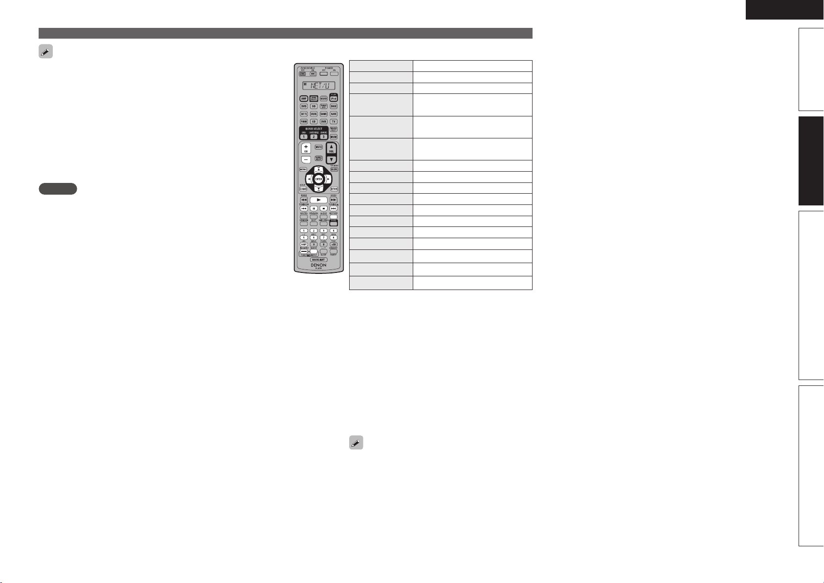
49
Simple version Advanced version Information
ENGLISH
Basic version
• You can specify the duration of the on-screen display to be displayed
(default: 30 sec) at menu “NET/USB” (vpage104). Press uio p
to return to the original screen.
• To play back compressed audio with extended bass or treble
reproduction, we recommend playback in RESTORER mode
(vpage92). The default setting is “Mode3”.
• If the USB memory device is divided into multiple partitions, only the
top partition can be selected.
• This unit is compatible with MP3 files conforming to “MPEG-1 Audio
Layer-3” standards.
• When USB on the sub remote control unit is pressed, playback starts
from the first file stored on the USB memory device.
NOTE
• Note that DENON will accept no responsibility whatsoever for any
problems arising with the data on a USB memory device when using
this unit in conjunction with the USB memory device.
• USB memory devices will not work via a USB hub.
• DENON does not guarantee that all USB memory devices will
operate or be supplied power. When using a USB portable hard disk
that can draw power from an AC adapter, we recommend using the
AC adapter.
• It is not possible to connect and use a computer via the USB port of
this unit using a USB cable.
Playing a USB memory device
n USB operation
Operation buttons Function
CH +, – Preset channel selection
MENU Amp menu
uio p
Cursor operation /
Auto search (cue, ui)
ENTER
(Press and release)
Enter / Pause
ENTER
(Press and hold)
Stop
SEARCH Page search
z1
/ Character search
z2
RETURN Return
1
Playback / Pause
8 9
Auto search (cue)
3
Pause
2
Stop
RESTORER RESTORER
1 – 8 Preset channel selection
SHIFT Preset channel block selection
TV POWER TV power on/standby (Default : SONY)
TV INPUT Switch TV input (Default : SONY)
• Repeat playback (vpage85 “Repeat”)
• Random playback (vpage85 “Random”)
• Slide show playback (vpage85 “Slide Show”)
z1 When the menu screen is displayed, press
SEARCH, then press o (previous page) or p
(next page).
To cancel, press ui or SEARCH twice.
z2 When the menu screen is displayed, press
SEARCH twice, then press o p to select the
first letter you want to search mode.
• If it is not possible to search the list, “unsorted
list.” is displayed.
To cancel, press ui or SEARCH.
If the list is not in alphabetical order, you may
not be able to perform a character search.
1.AVRA100E3_ENG_1st_0824.indd 49 2010/08/26 17:47:46
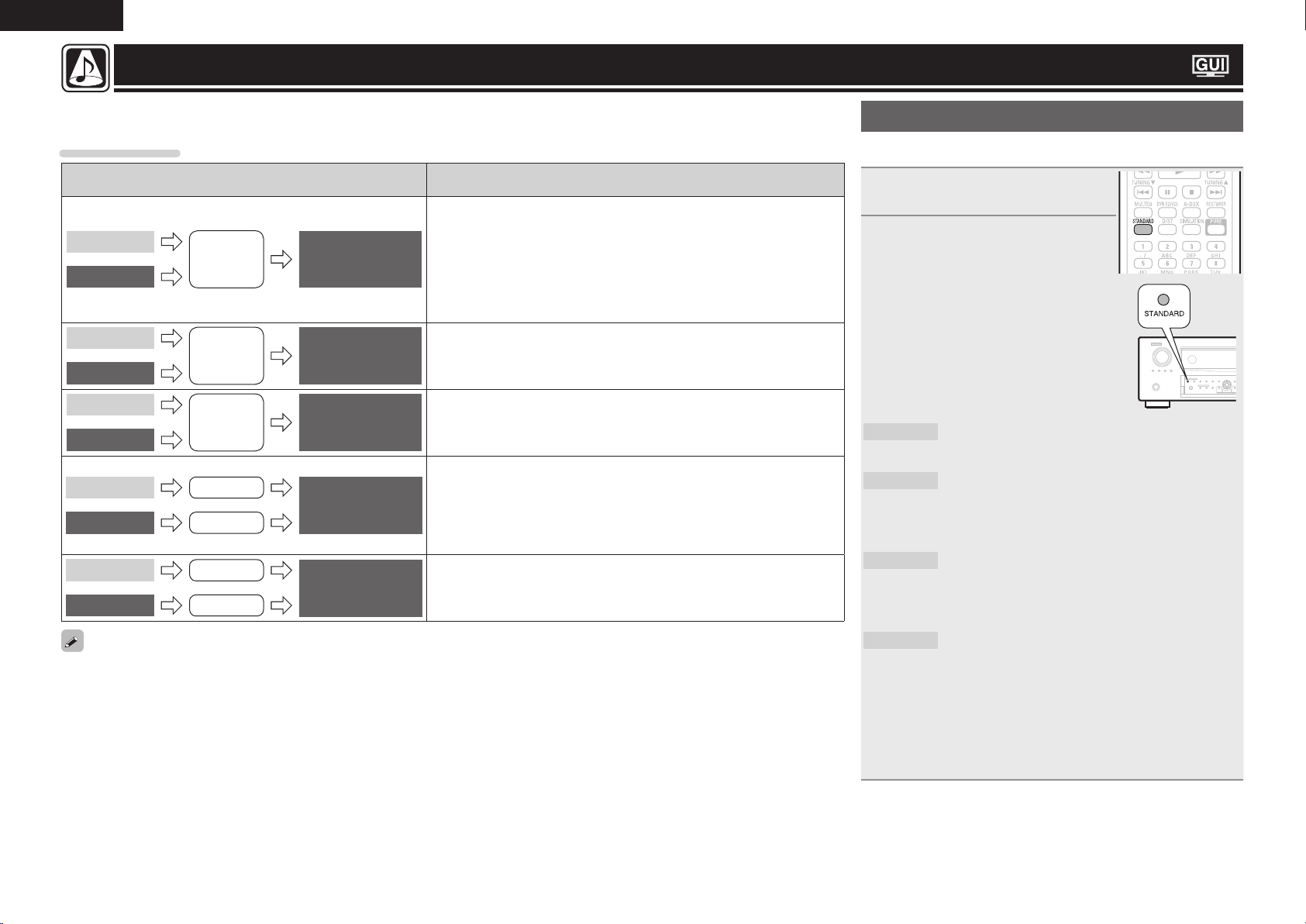
50
ENGLISH
Standard playback
n Surround playback of 2-channel sources
1
Playing the source (vpage 29 –
49).
2
Press STANDARD to select the
surround decoder to play back
multichannel sound.
• If STANDARD on the main unit is pressed,
the same function as with the remote
control unit can be obtained.
• Each time STANDARD is pressed, the
surround mode is switched.
Which decoder can be selected depends on
the settings of “Amp Assign” (vpage95)
or “Speaker Confi g.” (vpage95).
DOLBY PLgz
z1
This mode is for 7.1/9.1-channel surround playback
using the front height speakers.
• “PLgz Height” is displayed.
DOLBY PLgx
z2
This mode is for 7.1-channel or 6.1-channel
surround playback using the surround back
speakers.
• “PLgx Cinema”, “PLgx Music”or “PLgx Game”
is displayed.
DOLBY PLg
This mode is for 5.1-channel surround playback.
Select this mode if no front height speaker nor
surround back speaker is to be used.
• “PLg Cinema”, “PLg Music”, “PLg Game” or
“Pro Logic” is displayed.
DTS NEO:6
This mode is for 7.1-channel, 6.1-channel or
5.1-channel surround playback using the surround
back speakers.
• “DTS NEO:6 cinema” or “DTS NEO:6 music” is
displayed.
z1 This can be selected when “Speaker Confi g.” – “Front Height”
is not set to “None”.
z2 This can be selected when “Speaker Confi g.” – “Surround
Back” is not set to “None”.
Selecting a listening mode (Surround Mode)
This unit can play input audio signals in multi-channel surround mode or in stereo mode.
Select a listening mode suitable for the playback contents (cinema, music, etc.) or according to your liking.
Listening mode
Input audio
signal
Playback Listening mode
2-channel
Multi channel
Surround
Standard playback
(vpage50)
For 2-channel signal input:
• Surround-channel signals are created and played with surround playback.
For multichannel signal input:
• The surround signal recorded in source is played as surround playback.
(The sound is played according to the settings of the speaker size in
“Speaker Confi g.” (vpage95).)
• Surround-back-channel or front-height-channel signals that are not
recorded in source can be created.
2-channel
Multi channel
Surround
DENON original
surround playback
(vpage52)
The surround effects suitable for the source type or according to your
liking can be selected from the DENON original sound mode and is used
for playback.
2-channel
Multi channel
Stereo
Stereo playback
(vpage52)
• If multichannel signals are input, they are mixed down to 2-channel audio
and are played.
• Subwoofer signals are also output.
2-channel
Multi channel
Stereo
Surround
Direct playback
(vpage52)
Sound recorded in source is played as is.
• Surround back signals or front height signals are not created.
• In this mode, the following items cannot be adjusted.
• Tone (vpage88) • MultEQ
®
XT 32 (vpage89)
• Dynamic EQ
®
(vpage89) • Dynamic Volume
®
(vpage90)
• Dolby Volume (vpage91) • RESTORER (vpage92)
2-channel
Multi channel
Stereo
Surround
Pure direct playback
(vpage52)
This mode is for playback in higher sound quality than in ”Direct playback”
mode. The following circuits that affect sound quality are set to off.
• Main unit’s display circuit (The display is turned off.)
• Analog video input/output circuit
• Some listening modes cannot be selected, depending on the audio format or number of channels of the input signal. For details, see “Types
of input signals, and corresponding surround modes” (vpage129).
• Adjust the sound fi eld effect with the menu “Surround Parameters” (vpage86) to enjoy your favorite sound mode.
1.AVRA100E3_ENG_1st_0824.indd 50 2010/08/26 17:47:47
51
Simple version Advanced version Information
ENGLISH
Basic version
Standard playback
3
Select the mode corresponding to the playback
contents with the menu “Surround Parameters” –
“Mode” (vpage 86) to enjoy your favorite sound
mode.
Cinema
This mode is suited for movie sources.
Music
This mode is suited for music sources. More sound
is sent to the front speakers than in “Cinema”
mode.
Game
This mode is suited for games.
Pro Logic
This mode is suitable for playback of 2-channel
sources recorded with Dolby Pro Logic.
Height
z
This mode is for the surround decoder “Dolby
PLgz”. If the surround decoder is “Dolby PLgz”,
another mode cannot be selected.
z If the menu “Surround Parameters” – “PLgz Height” (vpage88)
is set to “ON”, the mode is switched to “Height” mode.
GViews on the displayH
q w
q Shows a decoder to be
used.
w Shows a Audyssey
DSX™ processing.
n Surround playback of multi-channel sources
(Dolby Digital, DTS etc.)
1
Playing the source (vpage 29 –
49).
2
Press STANDARD to select the
surround decoder to play back
multichannel sound.
• If STANDARD on the main unit is
pressed, the same function as with the
remote control unit can be obtained.
• Select the surround mode while
viewing the display on the screen
(v“Displaying the currently playing
surround mode” at right).
• Which decoder can be selected depends on the input signal,
the settings of “Amp Assign” (vpage95) or “Speaker Config.”
(vpage95).
Displaying the currently playing surround mode
Input signal Surround mode Display
DOLBY DIGITAL
(other than 2ch) /
DOLBY DIGITAL EX
DOLBY DIGITAL
DOLBY DIGITAL
DOLBY DIGITAL EX
DOLBY DIGITAL EX
DOLBY DIGITAL + PLgx
CINEMA
DOLBY D
PL x C
DOLBY DIGITAL + PLgx MUSIC
DOLBY D
PL x M
DOLBY DIGITAL + PLgz HEIGHT
DOLBY D
PL z
DOLBY DIGITAL Plus
DOLBY DIGITAL Plus
DOLBY DIGITAL +
DOLBY DIGITAL Plus + EX
DOLBY D +
EX
DOLBY DIGITAL Plus + PLgx
CINEMA
DOLBY D +
PL x C
DOLBY DIGITAL Plus + PLgx
MUSIC
DOLBY D +
PL x M
DOLBY DIGITAL Plus
+ PLgz
HEIGHT
DOLBY D + PL z
DOLBY TrueHD
DOLBY TrueHD
DOLBY TrueHD
DOLBY TrueHD + EX
DOLBY HD
EX
DOLBY TrueHD + PLgx CINEMA
DOLBY HD
PL x C
DOLBY TrueHD + PLgx MUSIC
DOLBY HD
PL x M
DOLBY TrueHD + PLgz HEIGHT
DOLBY HD
PL z
DTS (5.1ch) /
DTS-ES Discrete 6.1 /
DTS-ES Matrix 6.1 /
DTS 96/24
DTS SURROUND
DTS SURROUND
DTS + PLgx CINEMA
DTS
PL x C
DTS + PLgx MUSIC
DTS
PL x M
DTS + PLgz HEIGHT
DTS
PL z
DTS + NEO:6
DTS
NEO:6
DTS ES MTRX6.1
z1
DTS ES MTRX6.1
DTS ES DSCRT6.1
z2
DTS ES DSCRT6.1
DTS 96/24
z3
DTS 96/24
DTS-HD
DTS-HD HI RES
DTS-HD HI RES
DTS-HD MSTR
DTS-HD MSTR
DTS-HD + NEO:6
DTS-HD
NEO:6
DTS-HD + PLgx CINEMA
DTS-HD
PL x C
DTS-HD + PLgx MUSIC
DTS-HD
PL x M
DTS-HD + PLgz HEIGHT
DTS-HD
PL z
DTS Express
DTS Express
PCM (multi ch) /
DSD (multi ch)
MULTI CH IN
MULTI CH IN
MULTI IN + Dolby EX
MULTI
Dolby EX
MULTI IN + PLgx CINEMA
MULTI IN
PL x C
MULTI IN + PLgx MUSIC
MULTI IN
PL x M
MULTI IN + PLgz HEIGHT
MULTI IN
PL z
MULTI CH IN 7.1
z4
MULTI CH IN 7.1
All signals indicated
above
Audyssey DSX
z5
Audyssey DSX
z1 This is displayed when the input signal
is “DTS-ES Matrix 6.1” and this unit’s
“AFDM” (vpage87) setting is “ON”.
z2 This is displayed when the input signal is
“DTS-ES Discrete 6.1”.
z3 This is displayed when the input signal is
“DTS 96/24”.
z4 This mode is displayed for the PCM 7.1
channel signal input only.
z5 This surround mode is displayed when
“Audyssey DSX” (vpage90) is set to
“ON–Height/Wide–”, “ON–Height–” or
“ON–Wide–”.
GViews on the displayH
q w
q Shows a decoder to be used.
• A DOLBY DIGITAL Plus decoder is displayed
as “DOLBY D +”.
w Shows a decoder that creates sound output
from the surround back speakers.
• “+ PLgz” indicates the front height sound
from front height speakers.
For an input signal that can be reproduced in
each surround mode, see “Surround modes and
parameters” (vpage126).
1.AVRA100E3_ENG_1st_0824.indd 51 2010/08/26 17:47:48
52
ENGLISH
DENON original surround playback
1
Playing the source (vpage 29 –
49).
2
Press SIMULATION to select the
surround mode.
• If DSP SIMULATION on the main unit is
pressed, the same function as with the
remote control unit can be obtained.
• Each time SIMULATION is pressed, the
surround mode is switched.
MULTI CH
STEREO
This mode is for enjoying stereo sound from all
speakers.
WIDE SCREEN
This mode is for enjoying the atmosphere of
viewing a movie on a large screen.
SUPER
STADIUM
This mode is suited for viewing sports programs.
ROCK ARENA
This mode is for enjoying the atmosphere of a live
concert in an arena.
JAZZ CLUB
This mode is for enjoying the atmosphere of a live
concert in a jazz club.
CLASSIC
CONCERT
This mode is for appreciating classical concert
programs.
MONO MOVIE
z
This mode is for playing monaural movie sources
with surround sound.
VIDEO GAME
This mode is suited for achieving surround sound
with video games.
MATRIX
This mode lets you add a spacious feel to stereo
music sources.
VIRTUAL
This mode is for enjoying surround effects using
only the front speakers or headphones.
z When playing sources recorded in monaural in the “MONO
MOVIE” mode, the sound will be off balance with a single
channel (left or right), so input to both channels.
Depending on the program source being played, it may not be possible
to achieve a satisfactory surround effect. In this case, try other modes
to achieve a sound field suited to your tastes.
Stereo playback
This is the mode for playing in stereo. The tone can be adjusted.
• Sound is output from the front left and right speakers and subwoofer.
• If multichannel signals are input, they are mixed down to 2-channel
audio and are played.
1
Playing the source (vpage 29 –
49).
2
Press D/ST to select “STEREO”.
Stereo playback begins.
• If
DIRECT/STEREO on the main unit is
pressed, the same function as with the
remote control unit can be obtained.
Direct playback
Sound recorded in source is played as is.
• Surround back signals or front height signals are not created.
• In this mode, the following items cannot be adjusted.
• Tone (vpage88) • MultEQ
®
XT 32 (vpage89)
• Dynamic EQ
®
(vpage89) • Dynamic Volume
®
(vpage90)
• Dolby Volume (vpage91) • RESTORER (vpage92)
1
Playing the source (vpage 29 –
49).
2
Press D/ST to select “DIRECT”.
Direct playback begins.
• If
DIRECT/STEREO on the main unit is
pressed, the same function as with the
remote control unit can be obtained.
Pure direct playback
This mode is for playback in higher sound quality than in “Direct
playback” mode.
• The following circuits that affect sound quality are set to off.
• Main unit’s display circuit (The display is turned off.)
• Analog video input/output circuit
• Surround back signals or front height signals are not created.
• In this mode, the following items cannot be adjusted.
• Tone (vpage88) • MultEQ
®
XT 32 (vpage89)
• Dynamic EQ
®
(vpage89) • Dynamic Volume
®
(vpage90)
• Dolby Volume (vpage91) • RESTORER (vpage92)
1
Playing the source (vpage 29 –
49).
2
Press PURE.
The display goes dark, and pure direct
playback begins.
• If
PURE DIRECT on the main unit is
pressed, the same function as with the
remote control unit can be obtained.
• To cancel, press PURE again.
• Video signals are only output when HDMI signals are played in the
PURE DIRECT mode.
NOTE
When in the PURE DIRECT mode, the menu screen is not displayed.
1.AVRA100E3_ENG_1st_0824.indd 52 2010/08/26 17:47:48

Advanced
version
53
Simple version Information
ENGLISH
Advanced versionBasic version
F Speaker installation/connection (Advanced connection) vpage54
F Playback (Advanced operation) vpage65
F Playback in ZONE2/ZONE3 (Separate room) vpage72
F How to make detailed settings vpage75
F Operating the connected devices by remote control unit vpage108
Advanced version
Here, we explain functions and operations that let you make better use of this unit.
1.AVRA100E3_ENG_1st_0824.indd 53 2010/08/26 17:47:49
54
ENGLISH
This unit is equipped with a 9-channel built-in power
amplifi er and 11.2-channel PRE OUT connector that
enable it to handle various speaker systems.
This section provides the installation, connection,
and setup methods of speaker systems other
than the 7.1-channel system (with surround back
speakers).
For the speaker installation, connection, and setup
methods of the 7.1-channel system with surround
back speakers, see “Simple version (Simple setup
guide)” (vpage4).
Use Audyssey
®
Auto Setup function of this unit
to automatically detect the number of connected
speakers and perform optimal settings for the
speakers to be used.
Procedure for speaker settings
Install
Connect (vpage56)
Set up speakers (vpage63)
Install
This unit is compatible with Audyssey DSX™ (vpage132) and
Dolby Pro Logic gz (vpage133), which offers an even wider and
deeper surround sensation.
When using Audyssey DSX, install front wide speakers or front
height speakers.
When using Dolby Pro Logic gz, install front height speakers.
Install the surround back speakers in a position 2 to 3 ft (60 to 90 cm)
higher than ear level.
z1
z2
45˚
Surround
speaker
2 – 3 ft /
60 – 90 cm
GViewed from the sideH
Front height
speaker
• Point slightly
downwards
At least
3.3 ft / 1 m
Surround back
speaker
• Point slightly
downwards
Front
speaker
Front wide
speaker
z1 Recommended for Dolby Pro Logic gz
z2 Recommended for Audussey DSX
When 7.2ch / 9.2ch / 11.2ch (Surround back / Front
height / Front wide speaker) installed
FHRFHL
FL
FR
SL
SR
FWL
FWR
SW
1
SW
2
C
SBL SBR
z1
z2
z3
z5
z4
Listening
position
z1 22˚ – 30˚ z2 22˚ – 45˚ z3 55˚ – 60˚
z4 90˚ – 110˚ z5 135˚ – 150˚
Speaker installation/connection (Advanced connection)
1.AVRA100E3_ENG_1st_0824.indd 54 2010/08/26 17:47:49

55
Basic versionSimple version Information
ENGLISH
Advanced version
Install
When 6.1ch (Surround back speaker) installed
FL FR
C
SB
SL
SR
SW
z1
z2
Listening position
z1 22˚ – 30˚ z2 90˚ – 110˚
When 5.1ch installed
FL FR
SW
C
SL
SR
z1
z2
Listening
position
z1 22˚ – 30˚ z2 120˚
When Front A/B speakers installed
FR(A) FR(B)
SW
FL(B) FL(A)
Listening position
FL Front speaker (L) SBL Surround back speaker (L)
FR Front speaker (R) SBR Surround back speaker (R)
C Center speaker FHL Front height speaker (L)
SW Subwoofer FHR Front height speaker (R)
SL Surround speaker (L) FWL Front wide speaker (L)
SR Surround speaker (R) FWR Front wide speaker (R)
SB Surround back speaker
1.AVRA100E3_ENG_1st_0824.indd 55 2010/08/26 17:47:49
56
ENGLISH
Connect
• For the method of connecting 7.1-channel speakers, see page 5.
• For the method of connecting the TV, see page 6.
7.2- or 9.2-channnel (Surround back / Front height /
Front wide speaker) connection
The illustration on the right shows a connection example for performing
7.2-channel or 9.2-channel playback using the surround back, front
height, or front wide speakers.
If you connect the surround back, front height, and front wide speakers
before you start playback, the audio is played back by automatically
switching the speakers in accordance with the surround mode or input
signals.
To set the speakers for automatic switching, select “Amp Assign”
and set “Assign Mode” to “NORMAL” using steps 3 and 4 of “Set up
“Amp Assign”” (vpage63).
n For connecting two subwoofers
Two subwoofers can be connected to this unit.
To use two subwoofers, set “Subwoofer” to “2 spkrs” using the
“Speaker Config.” setting (vpage95).
For speaker impedance and speaker cable connections, see page 5.
FL
FR
C
SBL SBR
SL
SR
FWR
FWL
FHR
FHL
SW1 SW2
1.AVRA100E3_ENG_1st_0824.indd 56 2010/08/26 17:47:51
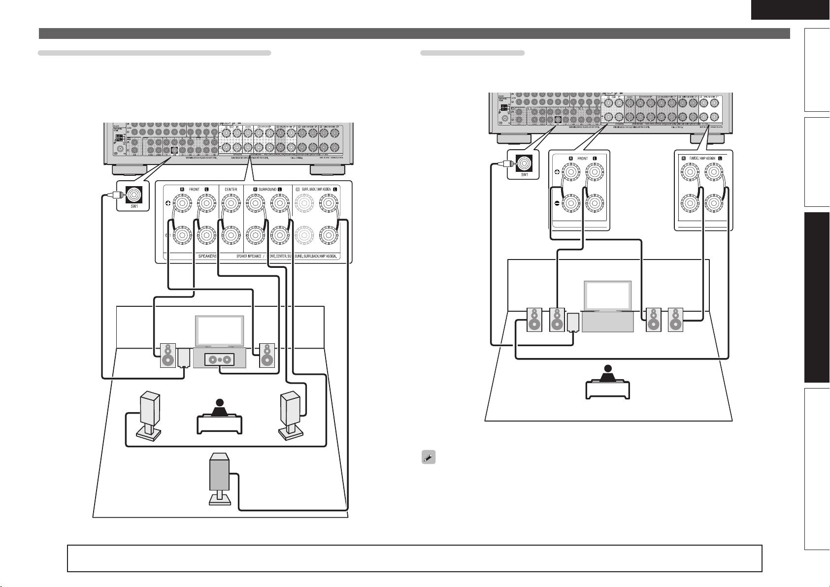
57
Basic versionSimple version Information
ENGLISH
Advanced version
Front A/B connection
You can connect a second set of speakers to this unit and use them for playback.
To use a second set of speakers, select “Amp Assign” and set “Assign Mode” to “Front B” using steps
3 and 4 of “Set up “Amp Assign”” (vpage63).
FL(A)FL(B) FR(B)FR(A)
SW
z You can also connect the Front B speakers to SURR.BACK/AMP ASSIGN or F.HEIGHT/AMP ASSIGN
speaker terminals using the “Amp Assign” and “Assign Sp.” settings (vpage95).
To perform multichannel playback, connect the center, surround, surround back, and front speakers, and
subwoofer.
Front speakers can be used separately, depending on the speaker’s specifications or playback source such
as front speakers (A) for multichannel playback and front speakers (B) for 2-channel playback (vpage98
“Front Speaker Setup”).
6.1-channel (Surround back speaker) connection
If using only one surround back speaker (with a 6.1-channel connection), connect to the “L” side of the
SURR. BACK/AMP ASSIGN terminal.
For speaker settings in this case, see “When 6.1ch (Surround back speaker) installed” (vpage55).
To perform 6.1-channel playback using the surround back speakers, select “Amp Assign” and set “Assign
Mode” to “NORMAL” using steps 3 and 4 of “Set up “Amp Assign”” (vpage63).
Also use the “Speaker Config.” setting (vpage95) to set “Surround Back” to “1 spkr”.
FL FR
C
SB
SL
SR
SW
Connect
For speaker impedance and speaker cable connections, see page 5.
1.AVRA100E3_ENG_1st_0824.indd 57 2010/08/26 17:47:52

58
ENGLISH
Connect
For speaker impedance and speaker cable connections, see page 5.
2.1-channel connection
FL FR
SW
Bi-Amp connection
You can use the front speakers via the bi-amp connection.
A bi-amp connection is to connect separate amplifiers to the tweeter terminals and woofer terminals of
speakers compatible with the bi-amp function. This prevents the back electromotive force (returned force
without output) of the woofer sent to the tweeter, which affects the sound quality of the tweeter, and you
can enjoy playback with higher-quality sound.
To use the bi-amp connection for the front speakers, select “Amp Assign” and set “Assign Mode” to
“Bi-AMP” using steps 3 and 4 of “Set up “Amp Assign”” (vpage63).
FL FR
SW
wq wq
(R) (L)
z You can also connect the front speakers for bi-amp connection to SURR.BACK/AMP ASSIGN or
F.HEIGHT/AMP ASSIGN speaker terminals using the “Amp Assign” – “Assign Sp.” settings (vpage95).
To perform multichannel playback, connect the center, surround, surround back, and front speakers, and
subwoofer.
NOTE
• Use speakers compatible with bi-amp connections.
• When making bi-amp connections, be sure to remove the short-circuiting plate or wire between the
speaker’s woofer and tweeter terminals.
1.AVRA100E3_ENG_1st_0824.indd 58 2010/08/26 17:47:54
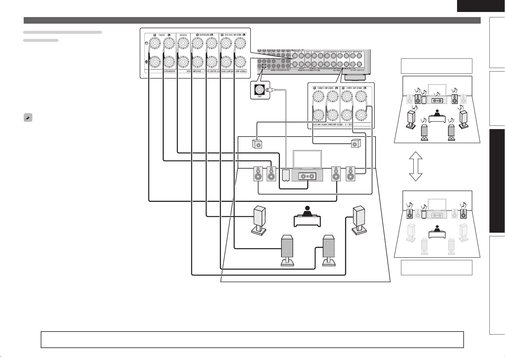
59
Basic versionSimple version Information
ENGLISH
Advanced version
For speaker impedance and speaker cable connections, see page 5.
Connect
FR
FR’
FL’
FL
C
SBL SBR
SL
SR
FHR
FHL
SW
Multi channel playback
(Surround mode)
2-channel playback
(Direct/Stereo mode)
Switching
z You can also change the 2-channel playback front speakers to SURR.BACK/AMP ASSIGN or F.HEIGHT/AMP ASSIGN speaker terminals using the “Amp
Assign” and “Assign Sp.” settings (vpage95).
Multi-channel + 2-channel
connection
You can connect the other front speakers for
2-channel playback using the DIRECT mode or
STEREO mode.
The speakers used exclusively for multichannel
playback and the speakers used exclusively for
2-channel playback are automatically switched for
playback in accordance with the surround mode.
To set the speakers for automatic switching during
playback, select “Amp Assign” and set “Assign
Mode”to “2CH” using steps 3 and 4 of “Set up
“Amp Assign”” (vpage63).
When you connect and use both surround back and
front height speakers, either set of speakers is used
for playback depending on the surround mode of
multichannel playback.
1.AVRA100E3_ENG_1st_0824.indd 59 2010/08/26 17:47:56
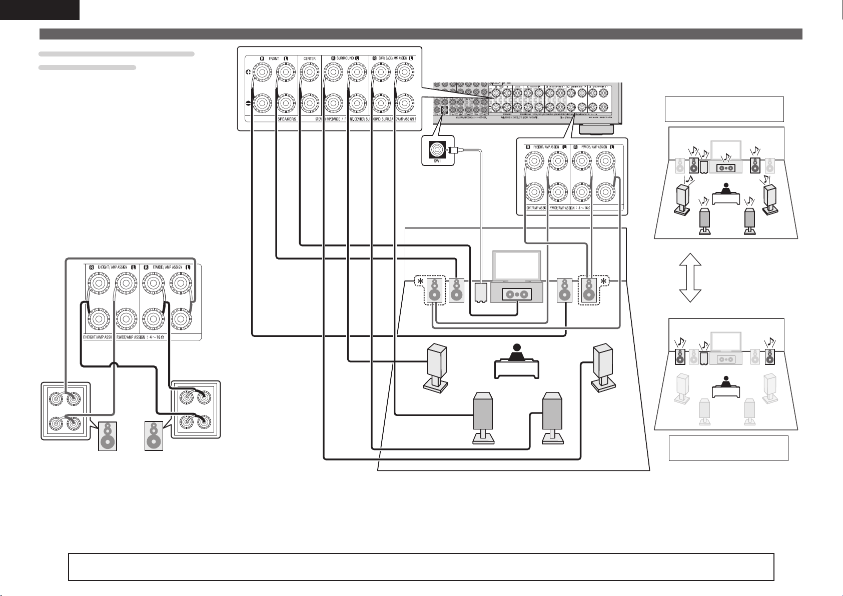
60
ENGLISH
Connect
Multi-channel + 2-channel with
Bi-Amp connection
You can connect the other front speakers for
2-channel playback using DIRECT mode or STEREO
mode via the bi-amp connection.
The speakers used exclusively for multichannel
playback and the speakers exclusively used for
2-channel playback are automatically switched for
playback in accordance with the surround mode.
To set the speakers for automatic switching during
playback via the bi-amp connection, select “Amp
Assign” and set “Assign Mode” to “2CH Bi-AMP”
using steps 3 and 4 of “Set up “Amp Assign””
(vpage63).
z Bi-Amp connection
FR
FR’
FL’
FL
C
SBL SBR
SL
SR
SW
Multi channel playback
(Surround mode)
2-channel playback
(Direct/Stereo mode)
Switching
For speaker impedance and speaker cable connections, see page 5.
FR’
FL’
wq
wq
1.AVRA100E3_ENG_1st_0824.indd 60 2010/08/26 17:47:57
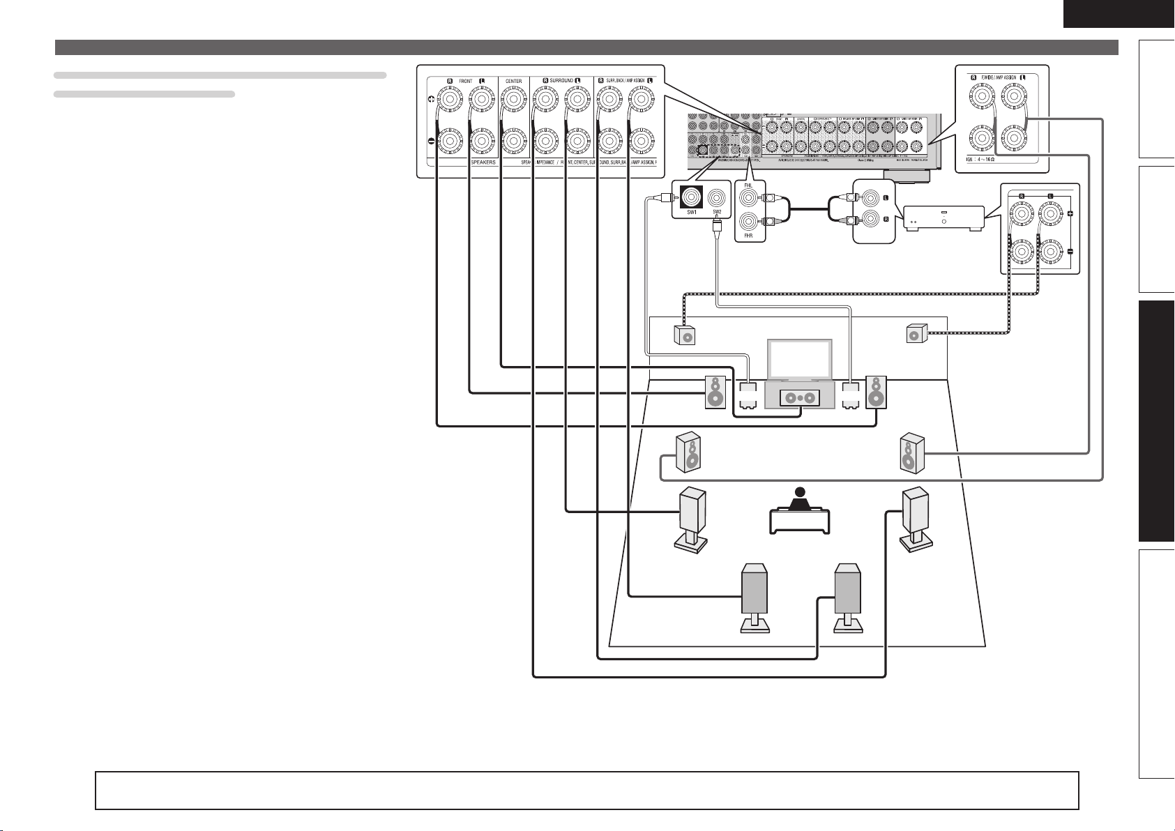
61
Basic versionSimple version Information
ENGLISH
Advanced version
Connect
For speaker impedance and speaker cable connections, see page 5.
11.2-channel (Surround back / Front height / Front
wide speaker) connection
You can perform playback using up to 11.2 channels using a
combination of the built-in power amplifier for 9-channel and an
external power amplifier for 2-channel. Connect the external amplifier
to the PRE OUT connector.
To perform 11.2-channel playback, select “Amp Assign” and set
“Assign Mode” to “11CH” using steps 3 and 4 of “Set up “Amp
Assign”” (vpage63).
FL
FR
C
SBL SBR
SL
SR
FWR
FWL
FHR
FHL
SW1 SW2
AUX IN
R
L
R
L
Power amplifier
z You can also change the PRE OUT connector for connecting the power amplifier to the Front channel using the “Amp Assign” – “Ext. Amp”
settings (vpage95). Change the setting in accordance with your preference.
1.AVRA100E3_ENG_1st_0824.indd 61 2010/08/26 17:47:59
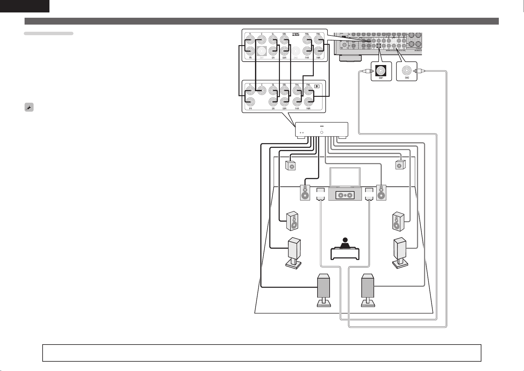
62
ENGLISH
Connect
For speaker impedance and speaker cable connections, see page 5.
PRE AMP mode
You can connect all speakers to an external power amplifier and use
this unit as a preamplifier.
Using this unit as a preamplifier, you can perform up to 11.2-channel
playback.
When the PRE AMP mode is used, the built-in power amplifier
operation of this unit is stopped, and interference to the preamplifier
from the power amplifier can be reduced.
To use this unit as a preamplifier, select “Amp Assign” and set
“Assign Mode” to “PRE AMP” using steps 3 and 4 of “Set up “Amp
Assign”” (vpage63).
• When the PRE AMP mode is used, the MAIN ZONE audio is not
output from the speaker terminals of this unit.
To use the speakers for multizone (ZONE2/ZONE3) in the PRE AMP
mode, set “Amp Assign” – “Assign Sp.” to “ZONE2/3” (vpage95).
This setting will output the ZONE2 audio from the surround back
speaker terminals and ZONE3 audio from the front wide speaker
terminals.
• For connecting power amplifier and speaker systems, refer to the
instruction manual supplied with the power amplifier to be used.
FL
FR
C
SBL SBR
SL
SR
FWR
FWL
FHR
FHL
SW1 SW2
Power amplifier
1.AVRA100E3_ENG_1st_0824.indd 62 2010/08/26 17:48:00
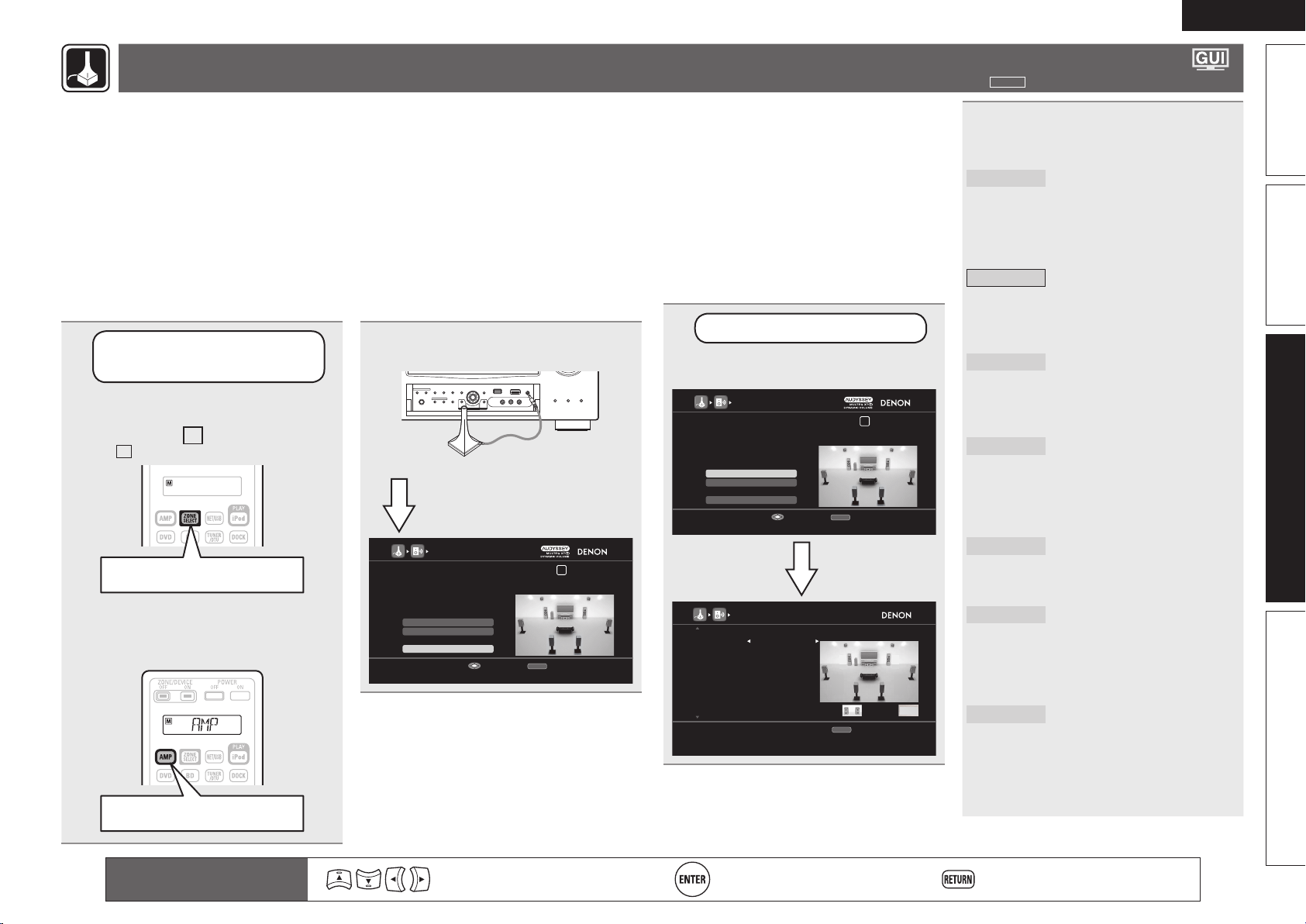
63
Basic versionSimple version Information
ENGLISH
Advanced version
Set up speakers
around items indicate the settings.
1
Set up the
remote control unit
n Set up the zone mode
Press ZONE SELECT to switch the
zone mode to
M
(MAIN ZONE).
The
M
indicator lights.
Press ZONE SELECT
n Set up the operation mode
Press AMP to set the remote control
unit to AMP-operation mode.
Press AMP
2
Connect the setup microphone.
AUDYSSEY AUTO SETUP
1 2 3 4 5 6
Amp Assign
RETURN
Auto Setup Start
Channel Select
STEP1 Preparation
Connect the speakers and place them according
to the recommendations in the manual,
Set the following items
If necessary.
Start Auto Setup
Enter Cancel
When the setup microphone is
connected, the following screen is
displayed.
This section provides the setup methods of speaker systems other than the 7.1-channel system (with surround back speakers).
For the setup methods of the 7.1-channel system with surround back speakers, see “Simple version”, “Set up speakers” (vpage7) of “Simple
version”.
First install and connect the speakers to this unit. Set the speaker impedance when using a speaker with impedance of 4 Ω or 6 Ω (vpage 98 “Speaker
Impedance”).
Before Auto Setup measurement, the settings shown below can be made.
• Changing the amplifi er assignment (Amp Assign)
The signal output from the SURR.BACK/AMP ASSIGN, F.HEIGHT/AMP ASSIGN or F.WIDE/AMP ASSIGN speaker terminal of this unit can be switched to match
your speaker environment (vpage63 “Set up “Amp Assign””).
• Setting the channels to be used (Channel Select)
If channels that are not to be used are set in advance, measurement for the set channels is skipped, and measuring time can be reduced. You can also change
the number of subwoofers or surround back speakers (vpage64 “Set up “Channel Select””).
3
Set up “Amp Assign”
Use ui to select “Amp Assign”,
and then press ENTER.
[1/2]
RETURN
Assign power amp to ZONE2 stereo signal
Return
Assign Sp. F.WIDE
Assign Mode ZONE2
ZONE2: ZONE3:
AMP ASSIGN
AUDYSSEY AUTO SETUP
1 2 3 4 5 6
Amp Assign
RETURN
Auto Setup Start
Channel Select
STEP1 Preparation
Connect the speakers and place them according
to the recommendations in the manual,
Set the following items
If necessary.
Change assigned power amp to match the speaker system
Enter Cancel
4
Use o p to select the con guration
of the connected speakers (“Assign
Mode”).
NORMAL
Select the NORMAL setting
to perform 7.2-channel or
9.2-channel playback using the
surround back, front height, or
front wide speakers. In this case,
go to step 8.
ZONE2
Select the ZONE2 setting to
assign the unit’s built-in power
amplifi er for ZONE2 and output
the audio in stereo. In this case,
go to step 5.
ZONE2/3
Select the ZONE2/3 setting to
assign the unit’s built-in power
amplifi er for ZONE2 and ZONE3
and output the audio in stereo. In
this case, go to step 8.
Z2/3-
MONO
Select the ZONE2/3-MONO
setting to assign the unit’s built-
in power amplifi er for ZONE2
and ZONE3 and output the audio
in monaural. In this case, go to
step 5.
Bi-AMP
Select the Bi-AMP setting to
connect the front speakers via
the bi-amp connection. In this
case, go to step 5.
2CH
When you perform 2-channel
playback in the DIRECT or
STEREO mode, select the 2CH
setting to use the other front
speakers for playback. In this
case, go to step 5.
2CH Bi-AMP
When you perform 2-channel
playback in the DIRECT or
STEREO mode, select the
2CH Bi-AMP setting to use the
other front speakers for Bi-Amp
playback. In this case, go to step
8.
Remote control operation
buttons
Move the cursor
(Up/Down/Left/Right)
Confi rm the setting Return to previous menu
1.AVRA100E3_ENG_1st_0824.indd 63 2010/08/26 17:48:00
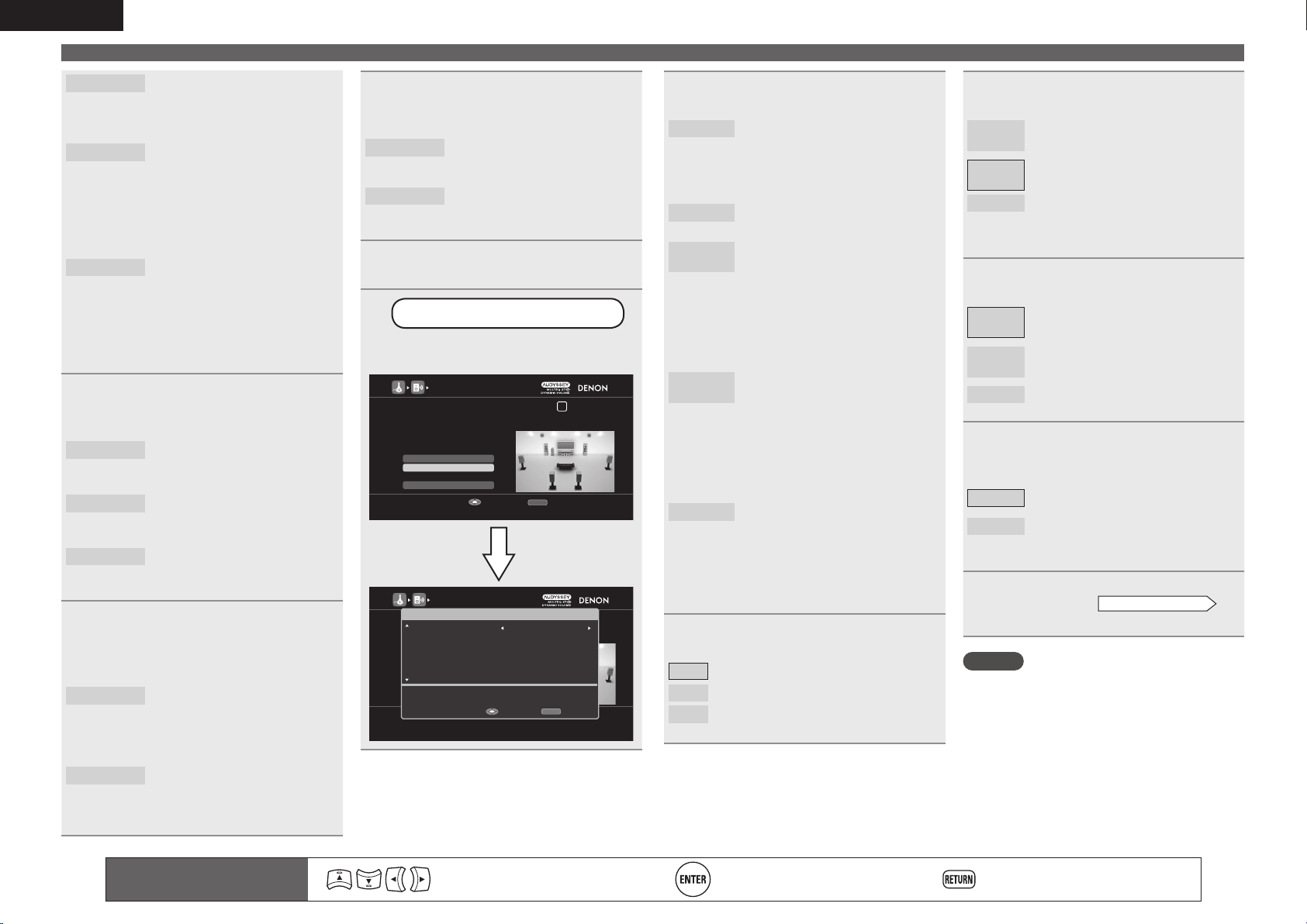
64
ENGLISH
Remote control operation
buttons
Move the cursor
(Up/Down/Left/Right)
Confi rm the setting Return to previous menu
Set up speakers
Front B
Select the Front B setting to use
the second set of front speakers
for playback. In this case, go to
step 5.
11CH
Select the 11CH setting to
perform playback using up to 11.2
channels using a combination of
the unit's built-in power amplifi er
for 9-channel and an external
power amplifi er for 2-channel. In
this case, go to step 6.
PRE AMP
Select the PRE AMP setting to
use this unit as a preamplifi er
by connecting all speakers to an
external power amplifi er. You
can perform up to 11.2-channel
playback. In this case, go to step
7.
5
Use i to select “Assign Sp.”, and
use o p to select a speaker for audio
output assigned by “Amp Assign”.
S.BACK
Select the S.BACK setting to
output the assigned audio from
the surround back speakers.
F.HEIGHT
Select the F.HEIGHT setting to
output the assigned audio from
the front height speakers.
F.WIDE
Select the F.WIDE setting to
output the assigned audio from
the front wide speakers.
6
Use i to select “Ext. Amp”, and
use o p to select the PRE OUT
connector to which an external
power ampli er is connected.
Height
Select the Height setting to
connect an external power
amplifi er to the front height (FHL/
FHR) terminals of PRE OUT
connector for playback.
Front
Select the Front setting to connect
an external power amplifi er to the
front (FL/FR) terminals of PRE
OUT connector for playback.
7
Use i to select “Assign Sp.”, and use
o p to set whether or not to use the
speaker terminals for multizone.
None
Select the None setting when you
do not want to use the speaker
terminals for multizone.
ZONE2/3
Select the ZONE2/3 setting when
you want to use the speaker
terminals for multizone.
8
Press RETURN to exit the “Amp
Assign” setting.
9
Set up “Channel Select”
Use ui to select “Channel Select”,
and then press ENTER.
AUDYSSEY AUTO SETUP
1 2 3 4 5 6
Amp Assign
RETURN
Auto Setup Start
Channel Select
STEP1 Preparation
Connect the speakers and place them according
to the recommen Measuren the manual,
Set the following items
If necessary.
Enable skip of measuring unused channels to reduce time
Enter Cancel
Channel Select
Subwoofer Measure (1 spkr)
Measure subwoofer channel (1 speaker)
Enter
Cancel
Surround Back Measure (2 spkrs)
Front Height Measure
RETURN
AUDYSSEY AUTO SETUP
1 2 3 4 5 6
Amp Assign
RETURN
Auto Setup Start
Channel Select
STEP1 Preparation
Connect the speakers and place them according
to the recommendations in the manual,
Set the following items
If necessary.
Enable skip of measuring unused channels to reduce time
Enter Cancel
10
Use ui to select a channel.
Front
Select for setting the front speakers
to be used. In this case, go to step
11.
• “Front” can be set when “Assign
Mode” is set to “Front B”.
Subwoofer
Select the number of subwoofers to
be used. In this case, go to step 12.
Surround
Back
Select the number of surround back
speakers to be used. In this case, go
to step 13.
• “Surround Back” cannot be set
when “Amp Assign” – “Assign
Mode” is set to “ZONE2/3” or
when “Assign Sp.” is set to
“S.BACK”.
Front
Height
Select for no front height speakers
to be used. In this case, go to step
14.
• “Front Height” cannot be set
when “Amp Assign” – “Assign
Mode” is set to “ZONE2/3”, “2CH
Bi-AMP” or when “Assign Sp.” is
set to “F.HEIGHT”.
Front Wide
Select for no front wide speakers to
be used. In this case, go to step 14.
• “Front Wide” cannot be set when
“Amp Assign” – “Assign Mode” is
set to “ZONE2/3”, “2CH Bi-AMP”
or when “Assign Sp.” is set to
“F.WIDE”.
11
Press o p to select a front speaker.
A
Select this to use front speaker A.
B
Select this to use front speaker B.
A+B
Select this to use front speakers A and B
simultaneously.
12
Use o p to set whether or not a
subwoofer channel is measured.
Measure
(2 spkrs)
Set for measuring two subwoofers
(multiple subwoofe calibration).
Measure
(1 spkr)
Set for measuring a subwoofer.
Skip
Set for no measuring of a subwoofer.
• When using two subwoofers, please select
“Measure (2 spkrs)”.
13
Use o p to set whether or not a
surround back channel is measured.
Measure
(2 spkrs)
Set for measuring two surround back
speakers.
Measure
(1 spkr)
Set for measuring a surround back
speaker.
Skip
Set for no measuring of a surround
back speaker.
14
Use o p to set whether or not front
height and front wide channels are
measured.
Measure
Set to measure the front height
speakers or front wide speakers.
Skip
Set when you do not want to measure
the front height speakers or front wide
speakers.
15
Press ENTER.
Proceed to page 9
STEP1 Preparation
step 6.
NOTE
After performing Audyssey
®
Auto Setup, do not
change the speaker connections or subwoofer
volume. In event of a change, perform Audyssey
Auto Setup again.
1.AVRA100E3_ENG_1st_0824.indd 64 2010/08/26 17:48:01
65
Basic versionSimple version Information
ENGLISH
Advanced version
n HDMI control function (vpage65)
n Sleep timer function (vpage66)
n Adjusting the volume of the speakers (vpage66)
n Quick select function (vpage67)
n REC OUT mode (vpage67)
n Party mode function (vpage68)
n Operating a media controller to play music and still
pictures (vpage69)
n Web control function (vpage70)
n Various memory functions (vpage71)
Playback (Basic operation) (vpage28)
Selecting a listening mode (Surround Mode)
(vpage50)
Playback (Advanced operation)
Convenient functions
HDMI control function
When you make an HDMI connection with a TV or player compatible
with this unit and HDMI control functions, you can perform the
following operations by setting the HDMI control function of each
device.
n This unit power off can be linked to the TV power off
step.
n You can switch audio output devices with a TV
operation.
When you set “Output audio from amp” in the TV audio output
setup operation, you can switch the amp power on.
n You can adjust this unit volume in the TV volume
adjustment operation.
n You can switch this unit input sources through
linkage to TV input switching.
n When playing the player, this unit input source
switches to the source for that player.
NOTE
• When “HDMI Control” – “Control” is set to “ON”, it consumes
more standby power.
• The HDMI control function controls operations of a TV that is
compatible with the HDMI control function. Make sure that the TV
and HDMI are connected when you perform HDMI control.
• Some functions may not operate depending on the connected TV
or player. Check the owner’s manual of each device for details
beforehand.
• When “Power Off Control” on the menu is set to “OFF” (vpage99),
this unit is not set to standby even if the connected device is in the
standby mode.
• When connection changes are implemented, such as adding
connections to HDMI devices, linked operations may be initialized.
In this case, you will need to reconfi gure the settings.
• When “HDMI Control” – “Control” is set to “ON”, it is not possible
to assign an HDMI connector to “TV” at “Input Assign” (vpage82).
1
Set the HDMI output connector corresponding with
the HDMI control function.
Set “HDMI Control” – “Control” (vpage99) to “ON“.
2
Turn the power on for all the equipment connected
by HDMI cable.
3
Set the HDMI control function for all equipment
connected by HDMI cable.
• Please consult the operating instructions for the connected
equipment to check the settings.
• Carry out steps 2 and 3 should any of the equipment be unplugged.
4
Switch the television input to the HDMI input
connected to this unit.
5
Switch this unit input to the HDMI input source and
check if the picture from the player is ok.
6
When you turn the TV’s power to standby, check
that the power of this unit also goes to standby.
If the HDMI control function does not operate properly, check the
following points.
• Is the TV or player compatible with the HDMI control function?
• Is “HDMI Control” – “Control” (vpage99) set to “ON”?
• Is “Power Off Control” (vpage99) set to “All” or “Video”?
• Is “Control Monitor” (vpage 99) set for the monitor output
connected to television?
• In the case of dual monitor connection, is “Control Monitor”
(vpage99) on the menu set to a monitor without HDMI control?
• Are the HDMI control function settings of all equipment correct?
NOTE
Should any of the operations below be performed, the interlocking
function may be reset, in which case, repeat steps 2 and 3.
• “Input Assign” – “HDMI” (vpage82) setting has changed.
• “Monitor Out” (vpage98) setting is changed.
• There is a change to the connection between the equipment and the
HDMI, or an increase in equipment.
1.AVRA100E3_ENG_1st_0824.indd 65 2010/08/26 17:48:01
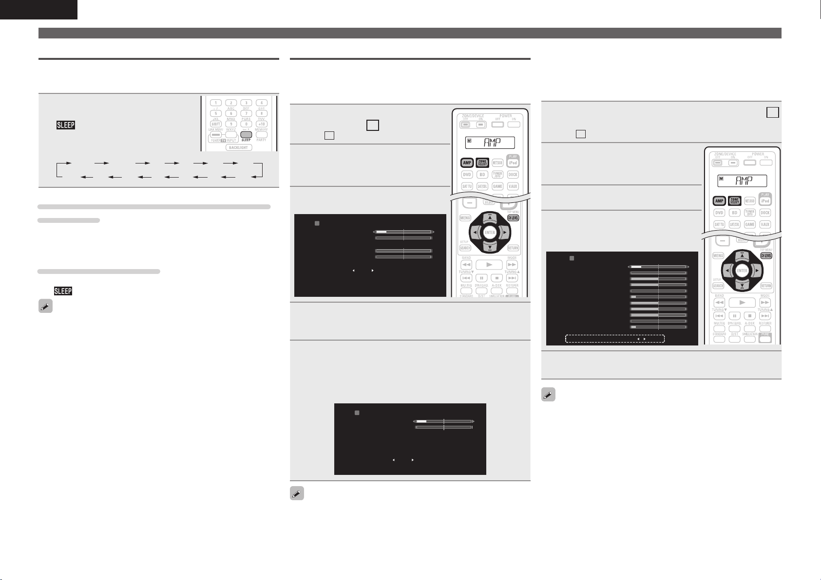
66
ENGLISH
Convenient functions
Sleep timer function
The power automatically goes into standby once the set time has
elapsed.
This is convenient for playing sources while going to sleep.
Press SLEEP and display the time you
want to set.
The indicator on the display lights.
• The time switches as shown below each
time SLEEP is pressed.
OFF 10 min 20 30 40 50
6080 7090100
110
120
To confirm the countdown time before putting the
unit to sleep
Press SLEEP.
“Sleep : zmin” appears on the display.
z Countdown time
To cancel the sleep timer
Press SLEEP to set “OFF”.
The
indicator on the display turns off.
• The sleep timer setting is canceled if this unit’s power is set to
standby.
• The sleep timer function can be set separately for the different zones
(vpage74 “Sleep timer function”).
Adjusting the volume of the speakers
You can adjust the channel level either according to the playback
sources or to suit your taste, as described below.
n Adjusting the volume of the different speakers
1
Press ZONE SELECT to switch the
zone mode to
M
(MAIN ZONE).
The
M
indicator lights.
2
Press AMP to set the remote
control unit to AMP-operation
mode.
3
Press CH LEVEL.
CHANNEL LEVEL
Front L
Front R
-8.0dB
-12.0dB
Subwoofer1
Subwoofer2
Subwoofer
0.0dB
0.0dB
ON
4
Use ui to select the speaker.
The speaker that can be set switches each time one of the
buttons is pressed.
5
Use o p to adjust the volume.
• You can directly turn “OFF” the subwoofer outputs during
2-channel playback in DIRECT or STEREO mode.
Select “Subwoofer” and use o p to select “ON” or “OFF”.
CHANNEL LEVEL
Front L
Front R
-8.0dB
-12.0dB
Subwoofer OFF
When a headphone jack is inserted, the headphone channel level can
be adjusted.
n Adjusting the volume of groups of speakers
(Fader function)
This function lets you adjust (fade) the sound all at once from the
front (front speaker / front height speaker / front wide speaker /
center speaker) or rear (surround speaker / surround back speaker).
1
Press ZONE SELECT to switch the zone mode to
M
(MAIN ZONE).
The
M
indicator lights.
2
Press AMP to set the remote
control unit to AMP-operation
mode.
3
Press CH LEVEL.
4
Press i to select “Fader”, then
select the item to be adjusting
using o p.
CHANNEL LEVEL
Front L
Front R
-8.0dB
-12.0dB
Fader Front Rear
Front Height L
Front Height R
0.0dB
0.0dB
Front Wide L
Front Wide R
-12.0dB
-10.0dB
0.0dB
0.0dB
Subwoofer2
Surround L
Center
Subwoofer1
0.0dB
-12.0dB
Surround R -10.0dB
5
Use o p to adjust the volume of the speakers.
(o : front, p: rear)
• The fader function does not affect the subwoofer.
• The fader can be adjusted until the volume of the speaker is adjusted
to the lowest value of –12 dB.
1.AVRA100E3_ENG_1st_0824.indd 66 2010/08/26 17:48:02
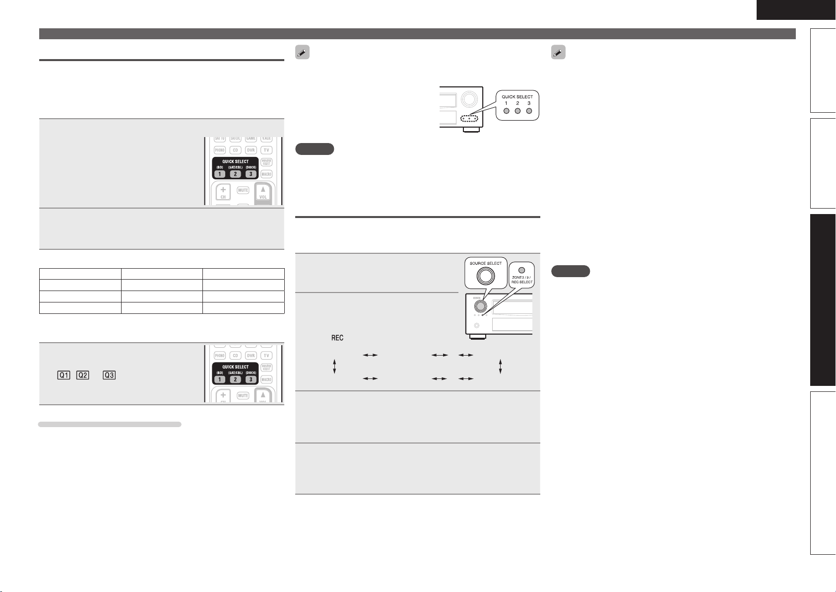
67
Basic versionSimple version Information
ENGLISH
Advanced version
Convenient functions
Quick select function
All of the settings in step 1 can be memorized together. By memorizing
frequently used settings, you can quickly access and enjoy a playback
environment that is consistently the same.
n Saving the settings
1
Set the items below to the settings you want to save.
q Input source (vpage28)
w Volume (vpage28)
e Surround Mode (vpage50)
r Video Select (vpage83)
t Audyssey Setting
(MultEQ
®
XT 32, Dynamic EQ
®
,
Dynamic Volume
®
) (vpage89)
2
Press and hold the desired QUICK SELECT until
“Memory” appears on the display.
The current settings will be memorized.
GQuick select defaultsH
Input source Volume
QUICK SELECT 1 BD –40 dB
QUICK SELECT 2 SAT/CBL –40 dB
QUICK SELECT 3 DOCK –40 dB
n Recalling the settings
Press QUICK SELECT at which the
settings you want to call out are saved.
The , or indicator illuminates on
the display.
Naming quick select settings
See “Quick Select Name” (vpage105).
• The Quick Select function can be set separately for the different
zones (vpage74 “Quick select function”).
• If QUICK SELECT on the main unit
is pressed, the same function as
with the remote control unit can be
obtained.
NOTE
Input sources stored with the quick select function cannot be selected
if they have been deleted at “Source Delete” (vpage104). In this case,
store them again.
REC OUT mode
When using the audio/video recording connectors (DVR outputs), you
can record the audio or video from a different program source while
listening to the currently played track.
1
Press ZONE2/3 / REC SELECT.
“ZONE2 SOURCE” is shown on the
display.
2
Turn SOURCE SELECT until
“RECOUT SOURCE” is
displayed.
The
indicator illuminates.
ZONE2 SOURCE ZONE2 PHONO ZONE2 HD Radio
····
RECOUT HD Radio RECOUT SIRIUS RECOUT SOURCE
····
3
Turn SOURCE SELECT to choose the input source to
be recorded.
• For operating instructions, refer to the respective equipment’s
operating instructions.
4
Start recording.
• For operating instructions, refer to the respective equipment’s
operating instructions.
• To cancel, press ZONE2/3 / REC SELECT, then turn SOURCE SELECT
until “ZONE2 SOURCE” is displayed.
• Make a test recording before starting the actual recording.
• Signals are only output to the analog REC OUT connectors when
the digital signals input to the digital input connectors (OPTICAL/
COAXIAL) are PCM (2-channel) signals.
• As the digital audio signal input from the HDMI or DENON LINK
connector is not output to the digital recording connector (OPTICAL),
you should connect using the OPTICAL and COAXIAL connectors.
• Sources selected with the REC OUT mode are output from ZONE2
as well.
• The operable buttons on the remote control unit in REC OUT mode
while it is in the operating mode for ZONE2 are as follows:
• ZONE/DEVICE power button
• Muting button
• Master volume control button
• The “HD Radio” digital audio output signals are not output from the
OPTICAL2 output connectors. Also, network audio signals (Internet
radio, media server, USB, Napster, Rhapsody and Pandora) are
output as copy-protected signals.
NOTE
• Recordings you make are for your personal enjoyment and should
not be used for other purposes without permission of the copyright
holder.
• Input sources for which “Delete” is selected at “Source Delete”
(vpage104) cannot be selected.
1.AVRA100E3_ENG_1st_0824.indd 67 2010/08/26 17:48:03
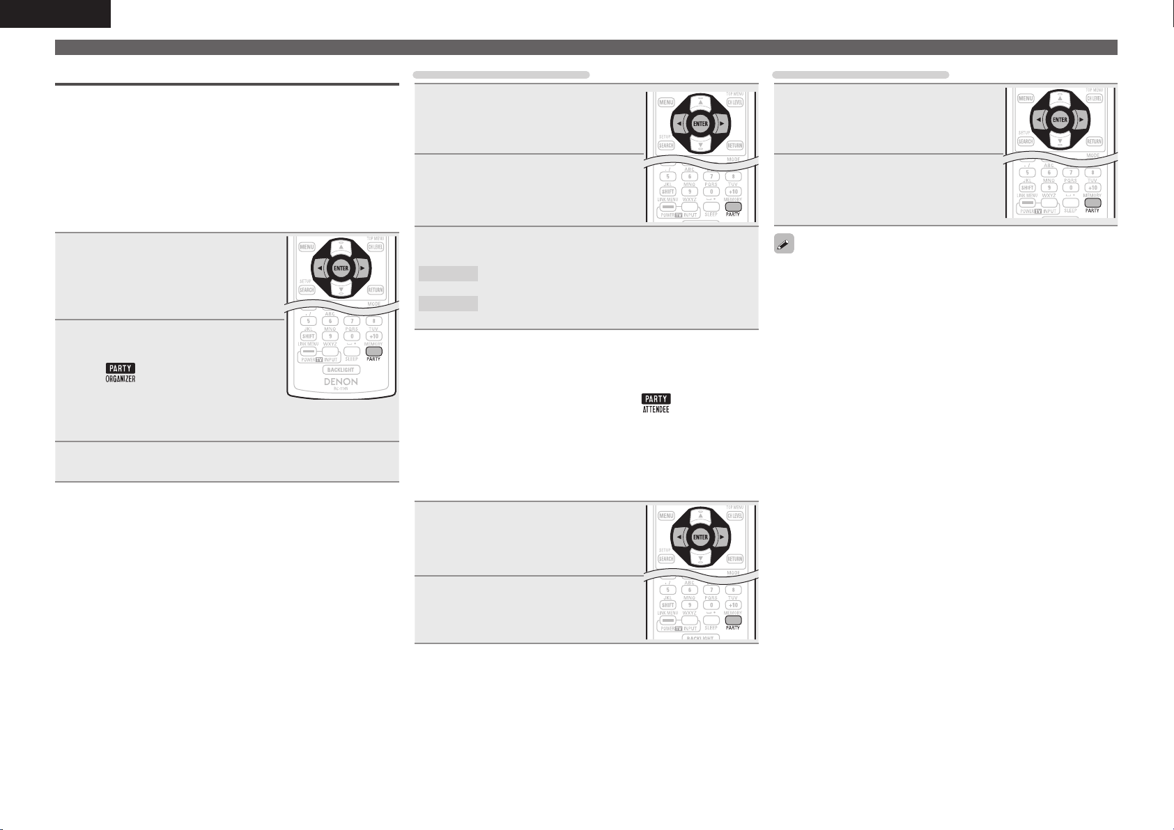
68
ENGLISH
Party mode function
The same network audio (Internet radio, Media server or iPod DIRECT)
can be played on multiple DENON products equipped with the Party
Mode function and connected in a network.
The party mode consists of one organizer and up to four attendees.
When one unit starts the party mode as the organizer, up to four devices
on which the party mode function is activated automatically participate
in the party as attendees. “Party Mode Function” (vpage102) must be
set to “ON” ahead of time in order to use the party mode function.
n Starting the party mode as the organizer
1
Press PARTY to become the
organizer.
“Enter Party Mode?” is displayed.
• An error message is displayed when you are
not connected to a network.
2
Press o p to select “Yes”, then
press ENTER.
The
indicator on the display
illuminates. The input source
automatically switches to “NET/USB”
and the attendees are automatically
selected.
3
Play the desired track.
Canceling the party mode
1
While in the party mode, press
PARTY.
“Exit Party Mode?” is displayed on the
menu screen.
2
Press o p to select “Yes”, then
press ENTER.
“Power off Attendees component?” is
displayed.
3
Press o p to select “Yes” or “No”, then press ENTER.
Yes
The power of the attendees is turned off and the party
mode is canceled.
No
The party mode is canceled without turning off the
power of the attendees.
n Participating in the party mode as an attendee
• When the organizer starts the party mode, up to four attendees are
selected automatically. No operation is required.
• When a device becomes an attendee,
appears on the
display.
The input source automatically switches to “NET/USB” and the
same network audio as on the organizer is played.
• If there are fewer than four attendees, a device can join the party
mode after it has started. To participate in the party mode, perform
the operation described below.
1
Press PARTY.
“Enter Party Mode?” is displayed.
• An error message is displayed when you are
not connected to a network.
2
Press o p to select “Yes”, then
press ENTER.
Convenient functions
Canceling the party mode
1
While in the party mode, press
PARTY.
“Exit Party Mode?” is displayed on the
menu screen.
2
Press o p to select “Yes”, then
press ENTER.
In this case, the other devices remain in
the party mode.
“Flickr”, “Napster”, “Pandora”, “Rhapsody” and “USB” are not
available in the Party Mode.
There can only be one organizer in the network. To form a new party
mode, first cancel the current party mode.
1.AVRA100E3_ENG_1st_0824.indd 68 2010/08/26 17:48:03
69
Basic versionSimple version Information
ENGLISH
Advanced version
Operating a media controller to play music and still pictures
• Perform this procedure using a media controller conforming to the DLNA (Digital Living Network Alliance)
standard.
• This function allows you to play content located on a computer (media server) or connected on a network
by operating a media controller on the same network.
• There are two types of operations on the media controller.
n Playing content on a computer (Media server)
Windows7 PC
(Windows Media Player 12)
Streaming Streaming
This unit
q Select content.
w Select a player.
e Start playback.
r Operate.
Wireless LAN-
compatible router
Computer
(Media server)
Media controller
1
From the media controller, browse the media server on the same network and
choose the content you want to play.
2
From the media controller, select this unit from among the products on the network.
Playback of the content selected in step 1 begins.
• When selecting this unit from the media controller, the name of this unit is displayed at “Friendly
Name” (vpage102 “Friendly Name Edit”).
• The following operations are possible from the media controller:
• File operations (play, stop, pause, track search)
• Play mode settings (repeat/random)
• Volume adjustment
n Playing contents on a media controller
Windows7 PC
(Windows Media Player 12)
This unit
q Select content.
w Select a player.
e Start
playback.
r Operate.
Wireless LAN-
compatible router
Media controller
1
Select the content you want to play from among the media controller.
2
From the media controller, select this unit from among the products on the network.
Playback of the content selected in step 1 begins.
• When selecting this unit from the media controller, the name of this unit is displayed at “Friendly
Name” (vpage102 “Friendly Name Edit”).
• The following operations are possible from the media controller:
• File operations (play, stop, pause, track search)
• Play mode settings (repeat/random)
• Volume adjustment
• is displayed on the menu screen while the media controller is being operated.
• For the various settings and operating procedures, see the operating instructions of the media controller
being used.
• When selecting this unit from the media controller, the name of this unit is displayed at “Friendly
Name”. “Friendly Name” can be edited at “Friendly Name Edit” (vpage102) as desired so that it is easily
distinguishable from other devices.
• When playback is started from the media controller, this unit’s input source automatically switches
to “NET/USB”. Also, when the “Network Standby” setting (vpage102) is set to “ON”, the power
automatically turns on.
NOTE
When operations related to browsing or playback (play, stop, pause, track search) are performed on this
unit while operating the media controller, the connection to the network is disconnected. The network
connection is also disconnected when the party mode is started.
Convenient functions
1.AVRA100E3_ENG_1st_0824.indd 69 2010/08/26 17:48:03
70
ENGLISH
Web control function
You can operate this unit using a browser.
1
Switch the “Network Standby” setting to “ON”.
(vpage 102).
2
Check the IP address of this unit with “Network
Info.” (vpage 103).
NETWORK INFO
DENON:[AVR-A100]Friendly Name
ON
192.168.100.19
DHCP
IP Address
0005cd004023
Mac Address
RETURN
Return
Checking the IP address.
3
Enter the IP address of this unit in browser’s address
box.
For example, if the IP address of this unit is “192.168.100.19”,
enter “http://192.168.100.19/”.
MAIN ZONE
-50.0dB
Status
ZONE2
-40dB
Status
ZONE3
Status
http://192.168.100.19/index.asp
INDEX
File
DENON Web Controller
AVR-A100
Edit View Tools HelpFavorites
q
q Entering the IP address.
4
When the top menu is displayed, click on the menu
item you want to operate.
MAIN ZONE
-50.0dB
Status
ZONE2
-40dB
Status
ZONE3
Status
Setup Menu
PDA Menu
Web Controller Config.
w
e
t
r
w Click when you operate each zone. (vGExample 1H)
e Click when you operate the setup menu. (vGExample 2H)
r Click to change the Web control screen setting.
(vGExample 3H)
t Click when you operate a small screen such as a PDA screen,
etc. (vGExample 4H)
5
Operate.
GExample 1H Main zone control screen
ZONE CONTROL
MAIN ZONE
POWER
MAIN ZONE
ON STANDBY
ON
DVD
OFF Sleep Timer
SOURCE
Player
Video
Network
Tuner
VOLUME -50.0dB
Note
To use the web control function,set the GUI menu “Manual Setup” - “Network Setup” -
>
∞ -80 18100-10-20-30-40-50-60-70
QUICK SELECT
>
CHANNEL LEVEL
>
NETAUDIO/USB
>
iPod Dock
>
iPod Direct
>
><
RELOAD
Add To Your Favorite
Top Menu
u
o
y
i
y Click to perform individual operations.
Changes to individual operation screens. (vGExample 5H)
u Click when you update to the latest information.
Normally, there is a change to the latest information each time
you operate. When operating from the main unit, click this or else
the screen will not be updated.
i Click to return to the top menu.
Displayed when setting “Top Menu Link Setup” to “ON” in
GExample 3H
o Click to add a setting to “Favorites” in your browser.
We recommend registering the setting screens for the different
zones in the browser’s favorites so as not to accidentally perform
menu operations for zones you do not intend to operate.
Convenient functions
1.AVRA100E3_ENG_1st_0824.indd 70 2010/08/26 17:48:04
71
Basic versionSimple version Information
ENGLISH
Advanced version
Convenient functions
GExample 2H Setup menu screen
SETUP MENU
SOURCE SELECT
Source
Input Assign
Video
Video Select
SAT/CBL
SOURCE
Auto
Auto
Video Convert ON
Analog Analog & HDMI OFF
Auto
********
480p/576p
AUTO VIDEO1 VIDEO2
Full Normal
1080i 720p 1080p 1080p:24Hz
OFF
Video Mode Auto Game Movie
i/p Scaler
Resolution(analog)
Resolution(HDMI)
Progressive Mode
Aspect
Input Mode
Input Mode
Decode Mode
SOURCE SELECT
SURROUND MODE
AUDIO/VIDEO ADJUST
MANUAL SETUP
INFORMATION
SAVE
LOAD
ReLoad
Rename
Source Level(analog)
0 Set
SAT/CBL Set Def
dB
<
<
Q0
Q2
Q3
Q4
Q5
Q1
Q0 Click the menu item from which you want to make settings.
The display on the right becomes the individual setting screens.
Q1 Click “SAVE” when you want to save settings, and click
“LOAD” when you want to call settings.
Q2 Click “v” and select from the displayed items.
Q3 Click an item to make a setting.
Q4 After entering characters, click “Set” to set, or click “Def” to
return to default setting.
Q5 Enter fi gures or click “<” or “>” to make the setting, and then
click “Set”.
GExample 3H Web confi guration screen
Web Controller Config.
Top Menu Link Setup
ON OFF
Back Top Menu
Q6
Q7
Q6 Click “ON” when performing Top Menu Link Setup.
When set up, return to the top menu from each operation screen.
(Default setting : “OFF”)
Q7 Click this item to return to the top menu.
GExample 4H PDA menu screen
DENON Web Controller
Main Zone Control
Multi Zone2 Control
Multi Zone3 Control
Q8
Q8 Select this item to operate each zone.
NOTE
You cannot change setup menu operations and zone name on the
PDA menu screen.
GExample 5H Net Audio operating screen
ZONE CONTROL
NET AUDIO/USB(MAIN ZONE)
DENON:[AVR-A100]
> Favorites
Internet Radio
Media Server
Flickr
ONE
MEMORY
ALL
REPEAT RANDOM
OFF ON OFF
PRESET OFF A1
-50.0dB
>
∞ -80 18100-10-20-30-40-50-60-70
QUICK SELECT
>
CHANNEL LEVEL
>
NET AUDIO/USB
>
iPod Dock
>
iPod Direct
>
RELOAD
><
[1/7]
PRESET MEMORY
Start End(Att ON) End(Att OFF)Party
CHARACTER SEARCH
Napster
Pandora
Rhapsody
Q9
W2
W6
W1W0
W4
W5
W3
Q9 Click the menu items. from which you want to play.
W0 Click “v” to select the preset channel you want to play.
W1 When registering presets, click “v” to select the channel you
want to register, and then click “MEMORY”.
W2 When searching using an acronym, click “v” and select from the
displayed characters.
W3 Click this item to play back repeatedly.
W4 Click this item when selecting menu items.
W5 Click to stop playback.
W6 Click this item to play back randomly.
GExample 6H Dedicated iPod Touch screen
Down Up
Zone Power
Source
Volume
-60 -50 -40 -30 -20 -10 0
iPod Dock iPod Direct NetAudio/USB
• When accessed from the iPod Touch browser, an optimized
operation screen is displayed.
Various memory functions
n Personal memory plus function
This function sets the settings (input mode, surround mode, HDMI
output mode, MultEQ
®
XT 32, Dynamic EQ
®
, Dynamic Volume
®
,
audio delay etc.) last selected for the individual input sources.
The surround parameters, tone settings and the volumes of the
different speakers are stored for the individual surround modes.
n Last function memory
This function stores the settings which were made before going
into the standby mode.
When the power is turned back on, the settings are restored.
1.AVRA100E3_ENG_1st_0824.indd 71 2010/08/26 17:48:05
72
ENGLISH
Playback in ZONE2/ZONE3 (Separate room)
• You can operate this unit so as to enjoy audio in a room (ZONE2, ZONE3) other than the MAIN ZONE
(room where the unit is located).
• You can simultaneously play back the same source in both the MAIN ZONE, ZONE2 and ZONE3. You can
also play back separate sources in the MAIN ZONE, ZONE2 and ZONE3.
The source selected for ZONE2 is also output from the recording output connectors.
Audio output
There are two methods to do this, as described below. Choose one of the methods.
q Zone playback by speaker output
w Zone playback by audio output (PRE OUT)
Use an external amplifier.
q Zone playback by speaker output
The ZONE2 and ZONE3 audio signals are output from this unit’s SURR.BACK/AMP ASSIGN, F.HEIGHT/
AMP ASSIGN or F.WIDE/AMP ASSIGN speaker terminals using the amplifier assignment function.
n Connecting and setting the speakers
“Assign Mode” setting
(vpage95) and audio signals
output
Connecting the speakers
ZONE2
ZONE2
Output signal :
Stereo (L / R)
ZONE2
w q w q
(L) (R)
ZONE2
and
ZONE3
ZONE2/3
Output signal :
Stereo (L / R)
ZONE3
w q w q
(L) (R)
ZONE2
w q w q
(L) (R)
ZONE2
and
ZONE3
ZONE2/3-
MONO
Output signal :
Monaural
ZONE2
w q
ZONE3
w q
When “Assign Mode” is set to “ZONE2” or “ZONE2/3-MONO”, you can change the AMP ASSIGN
speaker terminals for ZONE2 and ZONE3 in “Amp Assign” – “Assign Sp.” (vpage95).
w Zone playback by audio output (PRE OUT)
n Audio connections (ZONE2, ZONE3)
The audio signals of this unit’s ZONE2 and ZONE3 audio output terminals are output to the ZONE2 and
ZONE3 amplifiers and played on these amplifiers.
AUX INAUX IN
R
L
R
L
MAIN ZONE
ZONE2 ZONE3
This unit
We recommend using high quality pin-plug cables for audio connections in order to prevent noise.
NOTE
• When the input source to which the digital input connectors (OPTICAL/COAXIAL) are assigned is selected
in ZONE2 or ZONE3, playback is only possible if the digital signal being input is in PCM (2-channel) format.
• It is not possible to play the digital audio signals input from the HDMI or DENON LINK connectors in
ZONE2 and ZONE3. Use analog connections for ZONE2 or ZONE3 playback.
• When certain digital signals are being input, noise may be output from the ZONE2 and ZONE3 audio
output connectors.
Video output
Video Connection
The video signals of this unit’s ZONE2 video output terminal are played by the ZONE2 TV.
VIDEO
IN
ZONE2
VIDEO
MAIN ZONE
ZONE2
This unit
NOTE
It is not possible to output video signals input to the HDMI or component terminals to ZONE2.
1.AVRA100E3_ENG_1st_0824.indd 72 2010/08/26 17:48:05
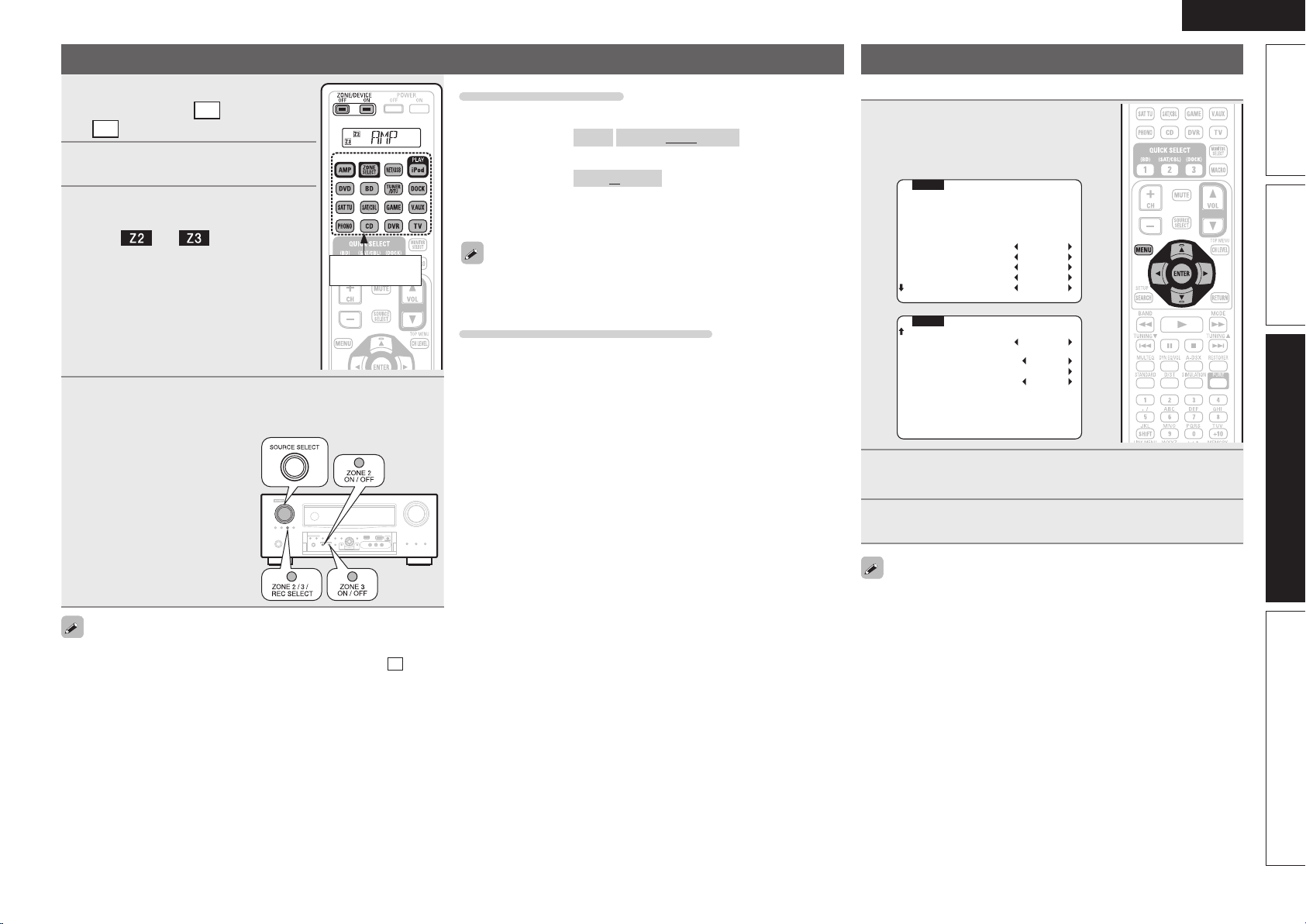
73
Basic versionSimple version Information
ENGLISH
Advanced version
Playback
1
Press ZONE SELECT to switch the
zone mode to
Z2
(ZONE2) or
Z3
(ZONE3).
Input source
select buttons
2
Press AMP.
3
Press ZONE/DEVICE ON to turn
on the ZONE2 or ZONE3 power.
The
or indicator on the
display lights.
• Also press input source select button when
in standby mode, the power turns on.
• When
ZONE/DEVICE OFF is pressed,
ZONE2 or ZONE3 turns off.
• Power in ZONE2 or ZONE3 can be turned
on or off by pressing ZONE2 ON/OFF or
ZONE3 ON/OFF on the main unit.
4
Press the input source select button.
The audio signal of the selected source is output to ZONE2 or
ZONE3.
• Turn
SOURCE SELECT after
pressing ZONE2/3 / REC SELECT
on the main unit to select an
input source.
When power for both MAIN ZONE and ZONE2 (ZONE3) is set to ON,
power of the MAIN ZONE only can be turned off. Select
M
(MAIN
ZONE) in step 1 then press ZONE/DEVICE OFF.
Adjusting the volume
Use VOL df to adjust the volume.
GAdjustable rangeH
– – –
–80dB – –40dB – 18dB
(When the “Volume Display” (vpage104) setting is “Relative”)
GAdjustable rangeH
0 – 41 – 99
(When the “Volume Display” (vpage104) setting is “Absolute”)
• At time of purchase, “Volume Limit” (vpage103) is set to “–10dB
(71)”.
Turn MASTER VOLUME after pressing ZONE2/3 / REC SELECT on the
main unit to adjust the sound volume.
Turning off the sound temporarily
Press MUTE.
The sound is reduced to the level set at “Mute Level” (vpage103) in
the menu.
• To cancel, either adjust the volume or press MUTE again.
• The setting is canceled when the zone’s power is turned off.
Menu Operation
The settings related to tone adjustment and volume can be made.
1
In the zone mode for which you
want to operate, press MENU.
The ZONE2 or ZONE3 menu is displayed
on the ZONE2 TV.
MENU ZONE2
INPUT :SAT/CBL
SIGNAL:ANALOG
VOL. :-40dB
>Bass 0dB
HPF OFF
Treble 0dB
Lch Lev. 0dB
Rch Lev. 0dB
>Channel STEREO
Vol.Lev. - VAR -
P.On Lev. LAST
Vol.Limit -10dB
Mute Lev. FULL
MENU ZONE2
2
Press uio p to select the menu to be set or
operated.
3
Press MENU to enter the setting.
The on-screen display disappears.
• For ZONE2, the “Zone Setup” can be made while watching the
on-screen display.
Also, when ZONE3 is operated, the on-screen display appears on
the ZONE2 monitor, so operation can be performed watching this
on-screen display.
• You can adjust these setting in “Zone Setup” (vpage103) in the
menu.
1.AVRA100E3_ENG_1st_0824.indd 73 2010/08/26 17:48:06
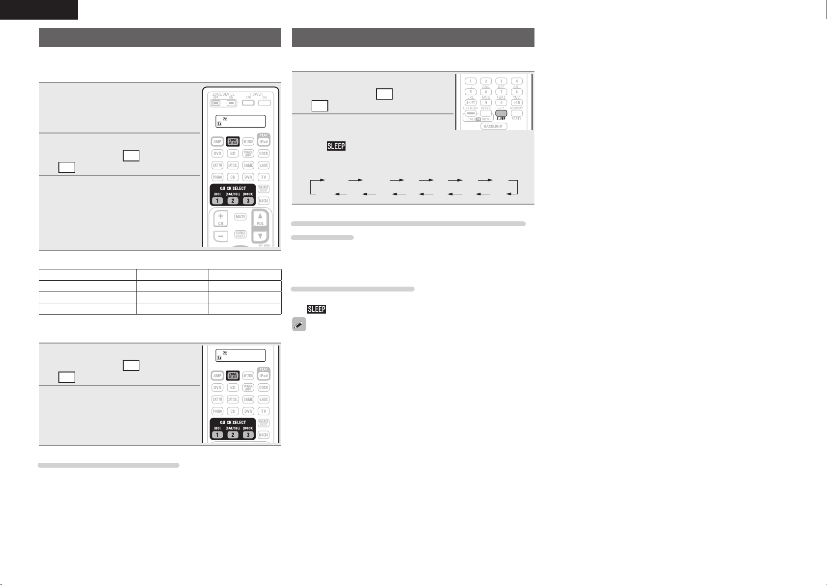
74
ENGLISH
Quick select function
It is also possible to save three settings for ZONE2 or ZONE3.
n Saving the settings
1
Set the items below to the settings
you want to save.
q Input source (vpage73)
w Volume (vpage73)
2
Press ZONE SELECT to switch the
zone mode to
Z2
(ZONE2) or
Z3
(ZONE3).
3
In the zone mode for which
you want to operate, press and
hold the desired QUICK SELECT
until “Memory” appears on the
on-screen display or display.
The current settings will be memorized.
GQuick select defaultsH
Input source Volume
Z2/Z3 QUICK SELECT 1 BD –40dB
Z2/Z3 QUICK SELECT 2 SAT/CBL –40dB
Z2/Z3 QUICK SELECT 3 DOCK –40dB
n Recalling the settings
1
Press ZONE SELECT to switch the
zone mode to
Z2
(ZONE2) or
Z3
(ZONE3).
2
Press QUICK SELECT at which
the settings you want to call out
are saved.
Naming quick select settings
See “Quick Select Name” (vpage105).
Sleep timer function
This is useful when you want to sleep while listening in ZONE2 or
ZONE3.
1
Press ZONE SELECT to switch the
zone mode to
Z2
(ZONE2) or
Z3
(ZONE3).
2
Press SLEEP and display the time
you want to set.
The
indicator on the display lights.
• The time switches as shown below each
time
SLEEP is pressed.
OFF 10 min 20 30 40 50
6080 7090100
110
120
To confirm the countdown time before putting the
unit to sleep
Press SLEEP.
“Z2 Sleep : zmin” or “Z3 Sleep : zmin” appears on the display.
z Countdown time
To cancel the sleep timer
Press SLEEP to set “OFF”.
The
indicator on the display turns off.
The sleep timer is also canceled when this unit is set to the standby
mode or the ZONE2 or ZONE3 power is turned off.
1.AVRA100E3_ENG_1st_0824.indd 74 2010/08/26 17:48:06
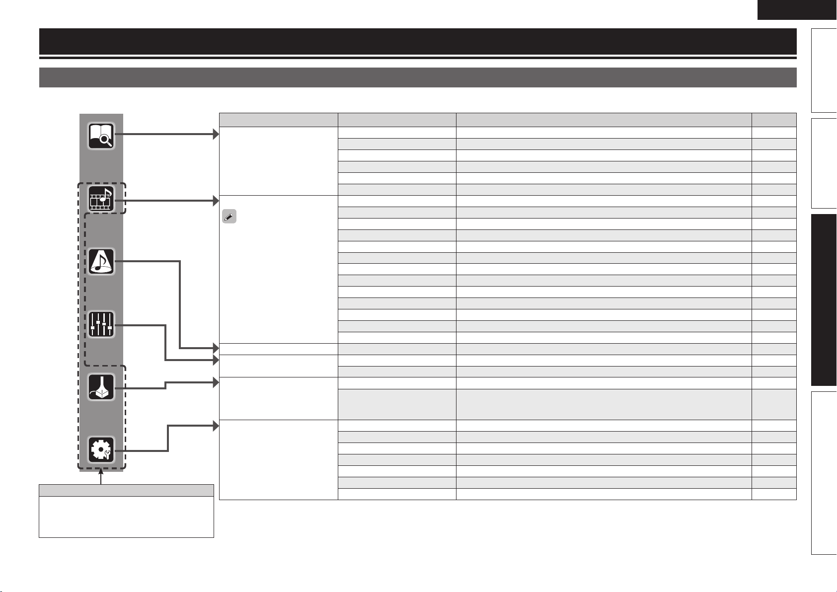
75
Basic versionSimple version Information
ENGLISH
Advanced version
Menu map
For menu operation, connect a TV to this unit and display the menu on the TV screen. For menu operations, see the following page.
How to make detailed settings
Setting items Detailed items Description Page
INFORMATION Status Shows information about current settings. 107
Audio Input Signal Shows information about audio input signals. 107
HDMI Information Displays the HDMI input/output signals and HDMI monitor information. 107
Auto Surround Mode Displays the settings stored for the auto surround mode. 107
Quick Select Displays the settings stored for the Quick Select function. 107
Preset Channel Shows information about tuner or network preset channels. 107
SOURCE SELECT
Displayed items of the
“SOURCE SELECT” menu
differs, depending on the
selected input source.
Play Displays the playback screen of each input source. 80
Auto Preset Uses the auto preset function to program radio stations. 81
Preset Skip Sets the preset memories that you do not want to display when tuning. 81
Parental Lock Sets the Parental Lock. 81
Antenna Aiming Adjusts the SIRIUS reception sensitivity. 81
Preset Name Assigns name to a preset memory. 81
Input Assign Changes input connector assignment. 82
Video Makes the video settings. 83
Input Mode Sets the audio input mode and decode mode. 84
Rename Changes the display name for this source. 85
Source Level Adjusts the playback level of the audio input. 85
Playback Mode Makes settings for iPod, USB memory device or network source playback. 85
Still Picture Makes settings for still picture playback. 85
SURROUND MODE Selects a listening mode. 50
AUDIO/VIDEO ADJUST Audio Adjust Adjusts various audio parameters. 86
Picture Adjust Adjusts the picture quality. 92
AUTO SETUP Audyssey Auto Setup Makes the optimum settings for the speakers being used automatically. 7
Parameter Check Checks Audyssey
®
Auto Setup measurement results.
This item is only displayed after Audyssey Auto Setup procedure has been
performed.
12
MANUAL SETUP Speaker Setup Sets the speaker size and distance, the channel level, etc. 93
HDMI Setup Makes settings for HDMI video/audio output. 98
Audio Setup Makes settings for audio playback. 99
Network Setup Makes network settings. 101
Zone Setup Makes settings for audio playback in a multi-zone (ZONE2/ZONE3) system. 103
Option Setup Makes various other settings. 104
Language Set the language for display the menu on the TV screen. 106
Items that only need to be set once
Set these for example upon purchase.
Once these items are set, there is no need to
set them again unless the speaker layout or the
connected speakers have been changed.
1.AVRA100E3_ENG_1st_0824.indd 75 2010/08/26 17:48:07
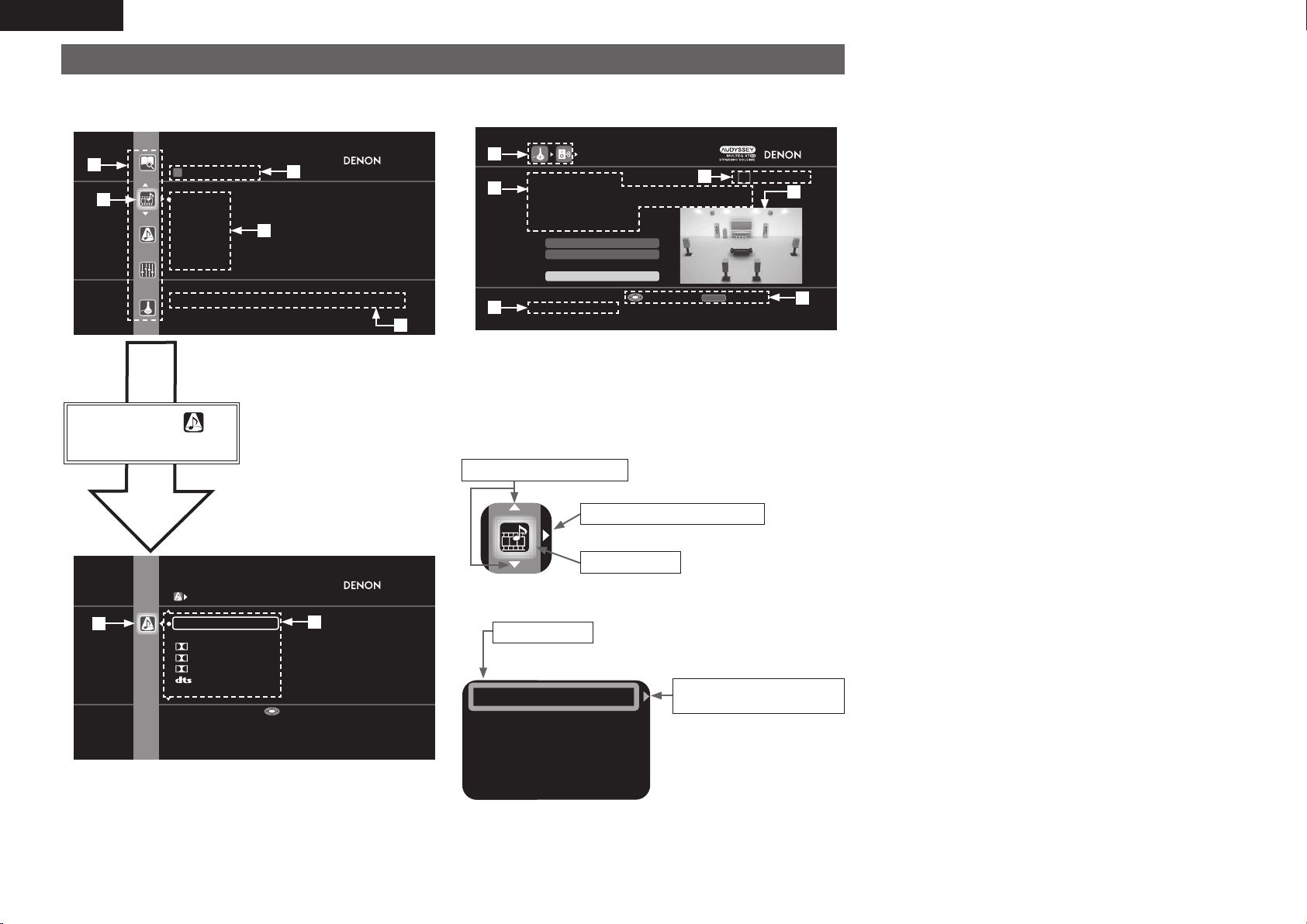
76
ENGLISH
Examples of menu screen displays
Typical examples are described below.
GExample 1H Menu selection screen (Top menu)
SURROUND MODE
STEREO
DIRECT
DOLBY PL IIz
DOLBY PL IIx
DOLBY PL II
DTS NEO:6
MULTI CH STEREO
Stereo playback mode with tone controls
Enter
q List of GUI menu setup icons
w Currently selected setup icon
e Currently selected setup item
r List of currently selected setup
subcategory
t Guide text for the currently selected
setup item
Press i to select and
then press p.
(Or press ENTER.)
y
u
SOURCE SELECT
SAT/CBL
DVR
GAME
V.AUX
DOCK
NET/USB
Select input source and make playback settings
e
r
t
w
q
y Selected setup icon
u Options of the selected setup item
GExample 2H Audyssey
®
Auto Setup screen
(with illustration)
AUDYSSEY AUTO SETUP
1 2 3 4 5 6
Amp Assign
RETURN
Auto Setup Start
Channel Select
STEP1 Preparation
Connect the speakers and place them according
to the recommendations in the manual.
Set the following items
if necessary.
Start Auto Setup
Enter Cancel
o
Q2
Q3
Q1
i History icon
o Operation guidance text
Q0 Operation step indicators
Q1 Illustration
Q2 Guide text for the currently selected setup item
Q3 Operation button guidance
i
Q0
n Icon
Proceed to the subcategory
Selected item
Switch the selected item
(Use i to switch.)
(Use
p or ENTER to switch.)
(Use u to switch.)
n List
Input Assign
Input Mode
Video
Rename
Source Level
Proceed to the
subcategory
• Switch the selected item using ui.
Selected item
(Use p or ENTER to switch.)
1.AVRA100E3_ENG_1st_0824.indd 76 2010/08/26 17:48:07
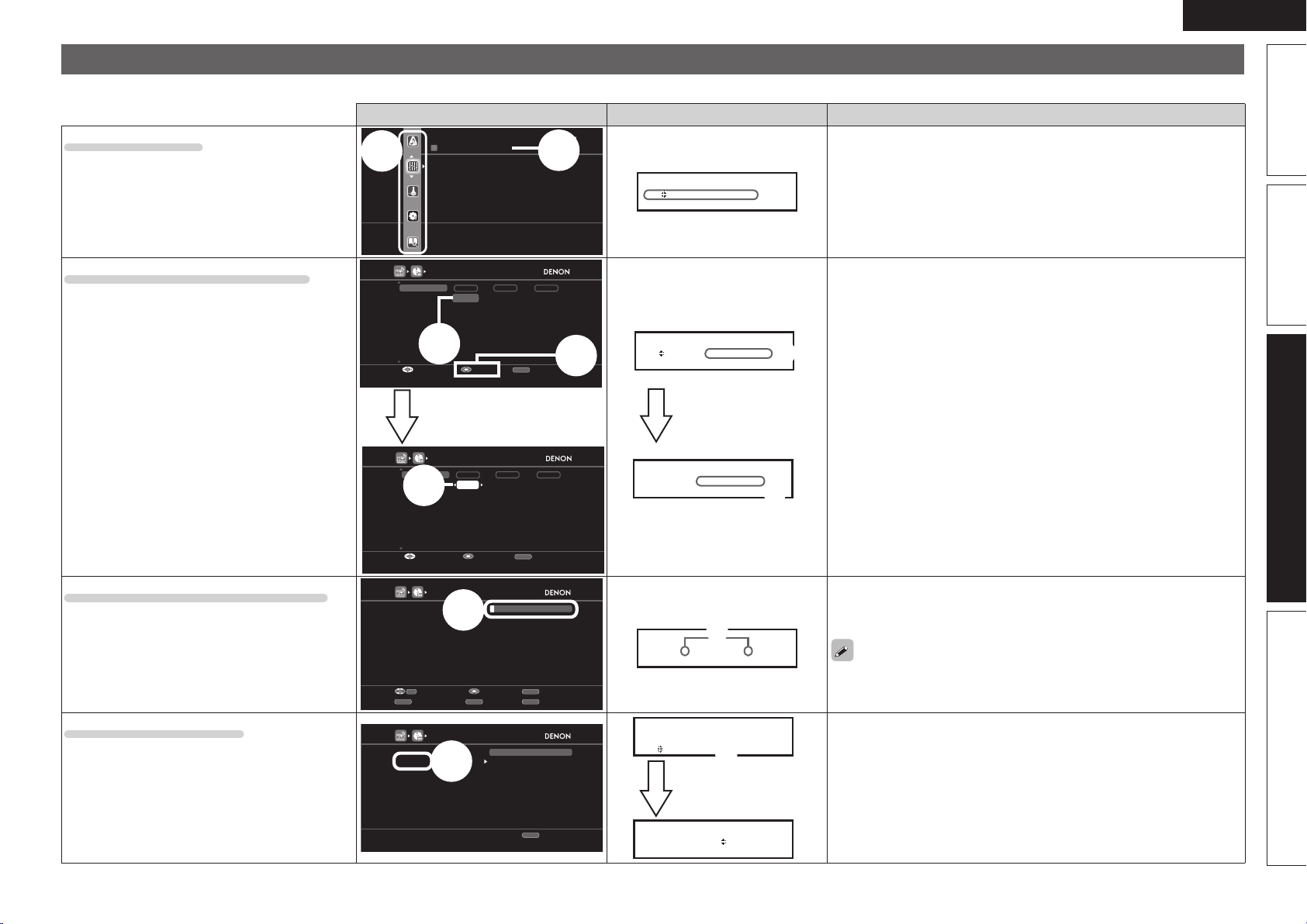
77
Basic versionSimple version Information
ENGLISH
Advanced version
Examples of menu and front display
Below we describe typical examples of displays on the TV screen and on the set’s display window.
Menu display Front display Description
Top menu display
q
w
AUDIO/VIDEO ADJUST
Audio Adjust
Picture Adjust
Adjust various audio and video
parameters
w
A /V A d ju st
A ut o S et up
q The menu items are displayed here.
w The selected line is displayed here.
The currently selected item is displayed on the display.
Use ui to move to the item you want to set.
Display when changing settings
q
w
HDMI1
HDMI2
None
HDMI3
HDMI4
HDMI5
HDMI7
None
COAX1
OPT1
COAX2
OPT2
None
None
None
1-RCA
None
2-RCA
3-RCA
None
None
INPUT ASSIGN
[1/2]
Default
Change HDMI input connector assignment
HDMI DIGITAL COMP
RETURN
EnterSelect Return
BD
DVD
TV
SAT/CBL
DVR
GAME
V.AUX
HDMI1
HDMI2
None
HDMI3
HDMI4
HDMI5
HDMI7
None
COAX1
OPT1
COAX2
OPT2
None
None
None
1-RCA
None
2-RCA
3-RCA
None
None
INPUT ASSIGN
[1/2]
Default
Assign HDMI 1 input connector
HDMI DIGITAL COMP
RETURN
EnterSelect Cancel
BD
DVD
TV
SAT/CBL
DVR
GAME
V.AUX
e
Press ENTER.
q
B D [H DMI 1 ]
D V D [H DMI 2 ]
e
B D •H DMI 1 –
Press ENTER.
q Use
uio p to move to the item you want to set.
w Press ENTER to set to the mode in which the setting can be made.
e 0 and 1 is displayed at the sides of item whose setting can be
changed. Use o p to change to the desired setting.
Display when inputting characters
q
BD
Default
RENAME
BD
RETURN
CH-CH+SEARCH
EnterInput Cancel
Keyboard Insert
Delete
0-9
q
< BD >
[ BD ]
q When o p is pressed, the cursor moves to the left or right.
When ui is pressed at the position where you want to input the
character, the character is input.
For inputting characters on a keyboard screen or with the number buttons
on the remote control unit, see page 78.
Display when resetting
q
BD
Default
RENAME
BD
No
Yes
RETURN
Return
D e fa ul t : No
Ye s
q
B D < BD >
D ef au l t –
Press ENTER.
q Press i to select “Default”, then press p to set.
w Press i to select “Yes”, then press ENTER.
1.AVRA100E3_ENG_1st_0824.indd 77 2010/08/26 17:48:09
78
ENGLISH
Inputting characters
You can change the names as desired using the “Preset Name”
(vpage81), “Rename” (vpage85), “Rhapsody Account”
(vpage103), “Napster Account” (vpage103), “Zone Rename”
(vpage105), “Quick Select Name” (vpage105) and character input
for the network functions.
For inputting characters, there are three methods, as shown below.
Method for inputting characters
Method Operations
Using the number
buttons
(Normal screen)
• Operating with the remote control unit.
• Multiple characters are assigned to
a button, and each time the button is
pressed, a character is switched.
Using the cursor buttons
(Normal screen)
• Operating with the remote control unit
or the main unit.
• Use
uio p and ENTER to input
characters.
Using the keyboard
screen
• Operating with the remote control unit.
• Select a character on the TV screen to
input characters.
Normal screen
n Display of a normal input screen
BD
Default
RENAME
BD
RETURN
CH-CH+SEARCH
EnterInput Cancel
Keyboard Insert
Delete
0-9
q
w
q Character input section
w Guide for operation buttons
Using the number buttons
1
Display the screen for inputting characters
(vpage 75 “Menu map”).
2
Place the cursor at the character to be changed with
o p and press the number button (0 – 9) until the
desired character is displayed.
• The types of characters that can be input are as shown below.
1 . @ - _ / : ˜ M N O m n o 6
A B C a b c 2 P Q R S p q r s 7
D E F d e f 3 T U V t u v 8
G H I g h i 4 W X Y Z w x y z 9
J K L j k l 5
0 (Space) ! “ # $ % & ‘ ( )
z
+ ,
; < = > ? [ \ ] ^ ` { | }
• When you press
SHIFT while you type in,
you can change uppercase characters to
lowercase and vice versa.
• For entering the characters assigned to one
number button continuously, press p to
move the cursor to the right after entering
a character then enter the next character.
• For entering characters assigned to
separate buttons, press the number button
continuously. The cursor automatically
moves to the next position, and the
entered character is registered.
3
Repeat step 2 to change the name then press ENTER
to register it.
Example: For changing the input source from “DVD” to “DENON”
q Place the cursor at “V”.
DVD
w Press
twice.
DED
“V” changes to “E”.
e Press
twice.
DEN
“E” is automatically registered, and “D” changes
to “N”.
r Press p.
DEN
“N” is registered.
t Press
three times.
DENO
Input “O”.
y Press p.
DENO
“O” is registered.
u Press
twice.
DENON
Input “N”.
i Press
ENTER to register the input source name.
1.AVRA100E3_ENG_1st_0824.indd 78 2010/08/26 17:48:10
79
Basic versionSimple version Information
ENGLISH
Advanced version
Inputting characters
Using the cursor buttons
1
Display the screen for inputting characters
(vpage 75 “Menu map”).
2
Use o p to set the cursor to the character you want
to change.
3
Use ui to change the character,
then press ENTER.
• The types of characters that can be input
are as shown below.
GUpper case charactersH
ABCDEFGHIJKLMNOPQRSTUVWXYZ
GLower case charactersH
abcdefghijklmnopqrstuvwxyz
GSymbolsH ! “ # $ % & ‘ ( )
z
+ , - . / : ; <
= > ? @ [ \ ] ^ _ ` { | } ˜
GNumbersH
0123456789 (Space)
• When you press
SHIFT while you type in, you can change
uppercase characters to lowercase and vice versa.
4
Repeat steps 2 and 3 to change the name then press
ENTER to register it.
Keyboard screen
n Display of a keyboard input screen
RENAME
RETURN
SHIFT
InputSelect
Cancel
a/A Normal
SEARCH
a/A SPACE INSERT DELETE OK
BDBD
a
n
0
_
b
c
1
/
d
q
3
˜
e
r
4
?
l
y
@
|
m
z
-
}
g
t
6
\
f
s
5
[
h
u
7
]
i
v
8
ˆ
k
x
.
{
j
w
9
`
c
p
2
:
r
q
Q0
w
e
t
o
y u i
q Character input section
w Cursor
e Keyboard section
r Uppercase and lowercase switch key
t Space key
y Cursor keys
u Insert key
i Delete key
o OK key
Q0 Guide for operation buttons
1
Display the screen for inputting characters
(vpage 75 “Menu map”).
2
Press SEARCH while a normal screen is displayed.
A keyboard screen is displayed.
3
Select a character to be changed.
q Press uio p to select
or .
w Press ENTER to place the
cursor at the character to be
changed.
Each time ENTER is pressed, the
cursor moves by one character.
4
Select a character to be input with uio p then
press ENTER.
• The types of characters that can be input are as shown below.
GUpper case characters/Numbers/SymbolsH
ABCDEFGHIJKLMNOPQRSTUVWXYZ
0123456789
! “ # $ % & ’ ( )
z
+ , ; < = >
GLower case characters/Numbers/SymbolsH
abcdefghijklmnopqrstuvwxyz
0123456789
. @ - _ / : ˜ ? [ \ ] ^ ` { | }
• When you press
SHIFT while you type in, you can change
uppercase characters to lowercase and vice versa.
5
Repeat steps 3 and 4 to change the name.
6
Use uio p to select
OK
, then press ENTER.
1.AVRA100E3_ENG_1st_0824.indd 79 2010/08/26 17:48:11
80
ENGLISH
SOURCE SELECT
Perform settings related to input source playback.
• You do not have to change the settings to use the unit. Make settings when needed.
Menu operation
1
Press ZONE SELECT to switch the zone mode to
M
(MAIN
ZONE).
The
M
indicator lights.
2
Press AMP to set the remote control unit to AMP-operation
mode.
3
Press MENU.
The menu is displayed on the TV screen.
4
Use ui to select the menu to be set or operated.
5
Press ENTER or p to enter the setting.
• To return to the previous item, press RETURN.
• Exiting the Menu, press MENU while the menu is displayed.
The menu display disappears.
Important information
n About the display of input sources
In this section, the confi gurable input sources for each item are shown as follows.
BD
DVD
TV
SAT/CBL
DVR
GAME
V.AUX
DOCK
NET/USB
Favorites
Internet Radio
Media Server
USB/iPod
Flickr
Pandora
Napster
Rhapsody
SIRIUS
HD Radio
PHONO
CD
NOTE
Input sources that have been set to “Delete” at “Source Delete” (vpage104) cannot be selected.
Items that can be set with the “SOURCE SELECT” procedure
AUTO PRESET
Start
Start the auto preset process
Enter
PRESET SKIP
Select preset numbers to skip
A
B
C
D
E
F
All
A1 FM 87.50MHz
A2 FM 87.90MHz
A3 FM 89.10MHz
A4 FM 93.30MHz
A5 FM 97.90MHz
PARENTAL LOCK
Editing LocK Code
Lock Setting
Edit Lock Code
PRESET NANE
Select the preset memory number
A
B
C
D
E
F
A1 FM 87.50MHz
A2 FM 87.90MHz
A3 FM 89.10MHz
A4 FM 93.30MHz
A5 FM 97.90MHz
A6 FM 98.10MHz
Adjust the position of the antenna to get best signal
Satellite
Terrestrial
ANTENNA AIMING
RETURN
Return
HDMI1
HDMI2
None
HDMI3
HDMI4
HDMI5
HDMI7
None
COAX1
OPT1
COAX2
OPT2
None
None
None
1-RCA
None
2-RCA
3-RCA
None
None
INPUT ASSIGN [1/2]
Default
Change HDMI input connector assignment
HDMI DIGITAL COMP
RETURN
EnterSelect Return
BD
DVD
TV
SAT/CBL
DVR
GAME
V.AUX
BD
Default
RENAME
BD
RETURN
Return
VIDEO
Switch video to your preferred video system
input source
Video Select
Video Mode
Video Convert
i/p Scaler
Resolution(analog)
Progressive Mode
SOURCE
BD
DVD
SAT/CBL
DVR
V.AUX
Auto
HDMI
Analog
EXT.IN
INPUT MODE
Input Mode
Decode Mode
Automatically detect input signal and perform
playbacK
Enter
PLAYBACK MODE
Make settings for repeat mode
Repeat
Shuffle
All
One
OFF
STILL PICTURE
Make slideshow settings
Slide Show
Interval
ON
OFF
Auto Preset (vpage81)
Input Assign (vpage82)
Rename (vpage85)Video (vpage83) Input Mode (Audio) (vpage84)
Playback Mode (vpage85) : DOCK
Still Picture (vpage85)
Preset Skip (vpage81) Parental Lock (vpage81)
Preset Name (vpage81)Antenna Aiming (vpage81)
BD
Adjust for equal playback level with other
sources
Enter
Input Assign
Video
Input Mode
Rename
Source Level (analog)
Source Level (digital)
0dB
Source Level (Audio) (vpage85)
PLAYBACK MODE
USB Select
Direct Play
Select front-panel port
Enter
Front
Rear
Playback Mode (vpage85) : NET/USB
Play
Displays the playback screen of each input source.
DOCK
NET/USB
SIRIUS
HD Radio
Favorites
Internet Radio
Media Server
USB/iPod
Flickr
Pandora
Napster
Rhapsody
Remote control operation
buttons
Move the cursor
(Up/Down/Left/Right)
Confi rm the setting Return to previous menu
1.AVRA100E3_ENG_1st_0824.indd 80 2010/08/26 17:48:11
81
Basic versionSimple version Information
ENGLISH
Advanced version
SOURCE SELECT
Setting items Setting details
Edit Lock Code
Change the password.
SIRIUS
1. Press ui to select “Edit Lock Code”, and then press p or ENTER.
2. Input current lock code (4 digits) using uio p or 0 – 9, and press
ENTER.
3. Input new lock code (4 digits) using uio p or 0 – 9, and press
ENTER.
4. Input new lock code (4 digits) again using uio p or 0 – 9, and press
ENTER.
5. Press ui to select “Execute”, and then press ENTER.
If the correct password is input, “Completed” is displayed, and the new
password is modified.
• If the old password is incorrectly input, “Current Lock Code is incorrect”
is displayed, and proceed again from step 1.
• If the password input is 3 digits or less, “Enter 4 digits number” is
displayed, and input again with a 4 digit password.
• If the new password is not correctly input, “New Lock Codes do not
Match” is displayed and the password does not change.
Antenna Aiming
Install the antenna with radio reception sensitivity set to maximum.
Setting items Setting details
Satellite
Indicate satellite signal
strength.
SIRIUS
Display Condition
Signal strength is excellent
Signal strength is good
Signal strength is weak
No signal
Terrestrial
Indicate terrestrial signal
strength.
SIRIUS
Preset Name
Assign name to a preset memory.
Setting items Setting details
A1 – G8
Select the preset channel.
HD Radio
• Up to eight characters can be input.
• For character input, see page 78.
Default
The changed preset name
is returned to the default
setting.
Yes : Reset to the defaults.
No : Do not reset to the defaults.
Remote control operation
buttons
Move the cursor
(Up/Down/Left/Right)
Confirm the setting Return to previous menu
Auto Preset
Use the auto preset function to program radio stations.
Setting items Setting details
Start
Start the auto preset
process.
HD Radio
If an FM station cannot be preset automatically, select the desired
station by tuning it in manually, then preset it manually.
Preset Skip Default settings are underlined.
Set preset channel to be skipped when selecting.
Setting items Setting details
A – G
Set the preset channels you
do not want to display. You
can set by preset memory
block (A to G) or by preset
channel (1 to 8).
SIRIUS
HD Radio
All : Skip all channels of the selected preset memory blocks.
1 – 8 : Set by individual preset channels in the currently selected preset
memory block.
• ON : Display the selected preset channel.
• Skip : Do not display the selected preset channel.
If you set the selected preset memory blocks to “Skip”, you can skip
by blocks (A – G).
Parental Lock Default settings are underlined.
For any channel, set the radio reception limits.
Setting items Setting details
Lock Setting
Set the channel radio
reception limits.
SIRIUS
1. Press ui to select “Lock Setting”, and then
press p or ENTER.
2. Pressing uio p or 0 – 9, input the password
(4 digits number) and press ENTER.
3. Select channel by pressing ui, and set the
lock by pressing o p.
Unlock : Do not lock selected channel(s).
Lock : Lock selected channel(s). When a Parental Locked channel is
tuned, “Enter Lock Code” is displayed, then input the password.
• The default password is “0000”.
• If the password is wrong, “Lock Code is incorrect” is displayed. Input
the correct password.
• While listening to the channel being played, you can also set parental
lock (vpage35).
1.AVRA100E3_ENG_1st_0824.indd 81 2010/08/26 17:48:12
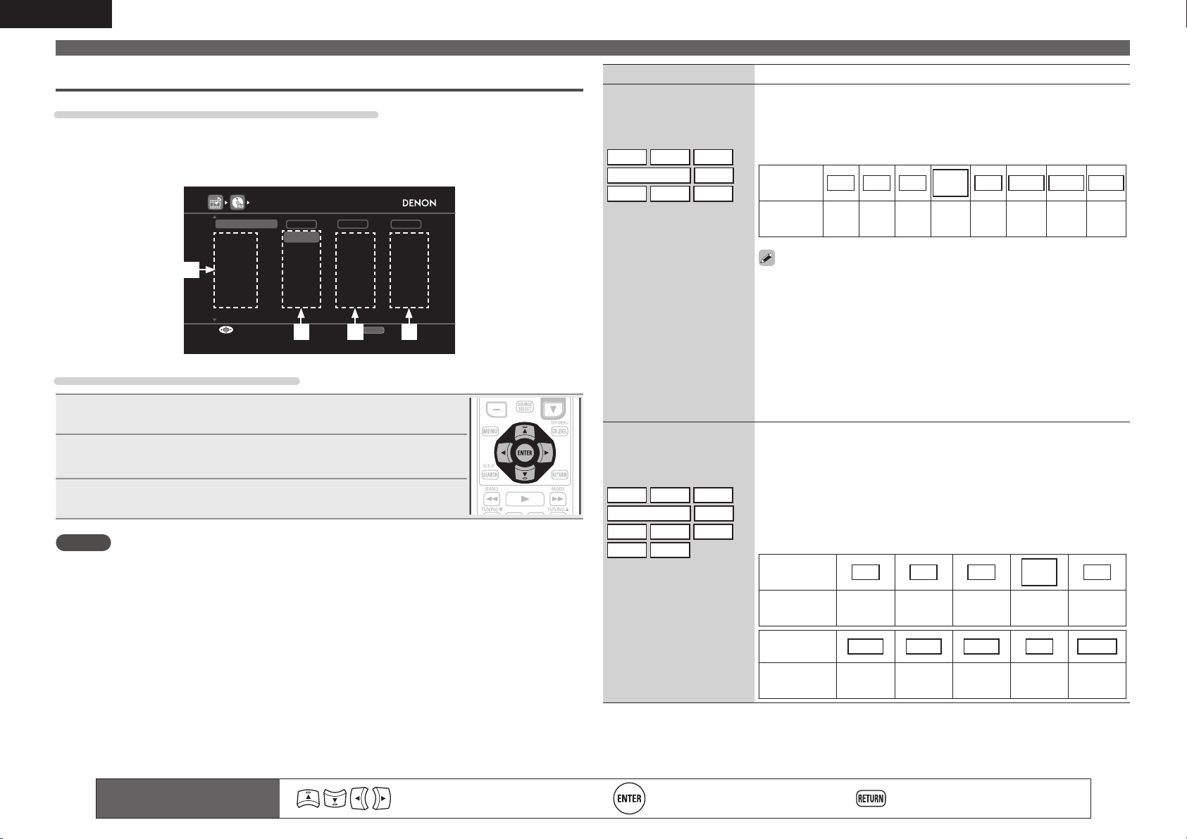
82
ENGLISH
Input Assign
Examples of input assign menu screen displays
This screen appears when the “SOURCE SELECT” – “each input source” – “Input Assign” menu is
selected. Use the “Input Assign” menu to change the w HDMI input connectors, e Digital input
connectors, and r component input connectors that are assigned to the q input sources in default
settings.
HDMI1
HDMI2
None
HDMI3
HDMI4
HDMI5
HDMI7
None
COAX1
OPT1
COAX2
OPT2
None
None
None
1-RCA
None
2-RCA
3-RCA
None
None
INPUT ASSIGN [1/2]
Default
Change HDMI input connector assignment
HDMI DIGITAL COMP
RETURN
EnterSelect Return
BD
DVD
TV
SAT/CBL
DVR
GAME
V.AUX
q
ew r
Input assignments menu operations
1
Use uio p to move the highlight to the item you want to set.
2
Press ENTER, then use o p to select the input connector to be
assigned.
3
Press ENTER to register the setting.
NOTE
If all “HDMI”, “DIGITAL” and “COMP” assignment of the Game source are set to “None”, Game source
cannot be selected with the input source selection.
SOURCE SELECT
Remote control operation
buttons
Move the cursor
(Up/Down/Left/Right)
Confi rm the setting Return to previous menu
Setting items Setting details
HDMI
Set this to change the HDMI
input connectors assigned
to the input sources.
BD
DVD
TV
SAT/CBL
DVR
GAME
V.AUX
DOCK
HDMI 1 / HDMI 2 / HDMI 3 / HDMI 4 / HDMI 5 / HDMI 6 / HDMI 7
None : Do not assign an HDMI input connector to the selected input
source.
• At time of purchase, the settings of the different input sources are as
shown below.
Input
source
BD DVD TV
SAT/
CBL
DVR GAME V.AUX
DOCK
Default
setting
HDMI
1
HDMI
2
None
HDMI
3
HDMI
4
HDMI
5
HDMI
7
HDMI
6
• An input source to which an HDMI input connector cannot be assigned
is displayed as “– – –”.
• To play the video signal assigned at “HDMI” combined with the audio
signal assigned at “Input Assign“ – “Digital”, select “Digital” at “Input
Mode” (vpage84).
• The audio signals input from the analog and digital connectors are not
output to the monitor.
• When a control dock for iPod is connected, signals cannot be assigned
to the HDMI connectors.
• When “HDMI Control” – “Control” (vpage99) is set to “ON”, HDMI
input connector cannot be assigned to “TV”.
DIGITAL
Set this to change the digital
input connectors assigned
to the input sources.
BD
DVD
TV
SAT/CBL
DVR
GAME
V.AUX
DOCK
CD
SIRIUS
COAX (coaxial) 1 – 2 / OPT (optical) 1 – 2 / D.LINK (DENON LINK)z
None : Do not assign a digital input connector to the selected input source.
z “D.LINK” is set when this unit is connected by DENON LINK to a
DENON Blu-ray disc / DVD player (vpage25 “Component equipped
with a DENON LINK connector”).
• For setting DENON LINK 4th, see page 29.
• At time of purchase, the settings of the different input sources are as
shown below.
Input source BD DVD TV
SAT/
CBL
DVR
Default
setting
None
COAX
1
OPT
1
COAX
2
OPT
2
Input source GAME V.AUX
DOCK
CD
SIRIUS
Default
setting
None None None None None
1.AVRA100E3_ENG_1st_0824.indd 82 2010/08/26 17:48:12
83
Basic versionSimple version Information
ENGLISH
Advanced version
SOURCE SELECT
Remote control operation
buttons
Move the cursor
(Up/Down/Left/Right)
Confirm the setting Return to previous menu
Setting items Setting details
Video Mode
Make settings for video
processing.
BD
DVD
TV
z
SAT/CBL
DVR
GAME
z
V.AUX
DOCK
Auto : Process video automatically based on the HDMI content
information.
Game : Always process video appropriate for game content.
Movie : Process video normally.
• If “Video Mode” is set to “Auto”, the mode is switched according to the
input contents.
• If a source is played in both MAIN ZONE (audio and video) and ZONE2
(audio only) modes in the same room, audio in MAIN ZONE and ZONE2
modes may sound out of synchronization, but this is not malfunction. In
this case, setting to “Game” mode may improve audio synchronization.
Video Convert
The input video signal is
converted automatically
in conjunction with the
connected TV (vpage15
“Converting input video
signals for output (Video
conversion function)”).
BD
DVD
TV
z
SAT/CBL
DVR
GAME
z
V.AUX
DOCK
ON : The input video signal is converted.
OFF : The input video signal is not converted.
• When a non-standard video signal from a game machine or some other
source is input, the video conversion function might not operate. In this
case set “Video Convert” to “OFF”.
• When “Video Convert” is set to “OFF”, the video conversion function
does not work. In this case, connect this unit and TV with the same type
of cable.
i/p Scaler
Convert the input source’s
resolution to the resolution
set at “Resolution”.
BD
DVD
TV
z
SAT/CBL
DVR
GAME
z
V.AUX
DOCK
NET/USB
Analog : Use i/p scaler function for analog video signal.
Analog & HDMI : Use i/p scaler function for analog and HDMI video signal.
HDMI : Use i/p scaler function for HDMI video signal.
OFF : Do not use i/p scaler function.
• “Analog & HDMI” and “HDMI” can be set for input sources for which an
HDMI input connector is assigned.
• Which items can be set depend on the input source assigned to each
input connector.
• This function is not effective when the input signal is x.v.Color, 3D,
sYCC 601 color, Adobe RGB color, Adobe YCC 601 color or computer
resolution.
Setting items Setting details
COMP (Component video)
Set this to change the
component video input
connectors assigned to the
input sources.
BD
DVD
TV
SAT/CBL
DVR
GAME
V.AUX
DOCK
1-RCA / 2-RCA / 3-RCA
None : Do not assign a component video input connector to the selected
input source.
• At time of purchase, the settings of the different input sources are as
shown below.
Input
source
BD DVD TV
SAT/
CBL
DVR GAME V.AUX
DOCK
Default
setting
None 1-RCA None 2-RCA 3-RCA None None None
• An input source to which an component video input connector cannot be
assigned is displayed as “– – –”.
• When a control dock for iPod is connected, signals cannot be assigned
to the component video connectors.
Default
The “Input Assign” settings
are returned to the default
settings.
Yes : Reset to the defaults.
No : Do not reset to the defaults.
If you select “Default” and press ENTER, the message “Return all
settings to the default?” is displayed. Select “Yes” or “No”, and then
press ENTER.
Video Default settings are underlined.
Set the source video.
z “TV” or “GAME” can be set when “HDMI” (vpage82) or “COMP” (vpage83) has been assigned.
Setting items Setting details
Video Select
Video of another input
source is played back
combined with the playing
audio.
SOURCE : Play the picture and sound of the input source.
BD / DVD / TV / SAT/CBL / DVR / GAME / V.AUX / DOCK : Select video
input source to view. This can be set for individual input sources.
“TV” and “GAME” can be selected only when a component video is
assigned as an input source.
NOTE
• It is not possible to select HDMI input signals.
• Input sources for which “Delete” is selected at “Source Delete”
(vpage104) cannot be selected.
1.AVRA100E3_ENG_1st_0824.indd 83 2010/08/26 17:48:13
84
ENGLISH
Setting items Setting details
Resolution
Set the output resolution.
You can set “Resolution”
separately for HDMI output
of the analog video input
and HDMI input.
BD
DVD
TV
z
SAT/CBL
DVR
GAME
z
V.AUX
DOCK
NET/USB
Auto : The number of pixels the TV connected to the HDMI output
connector supports is detected automatically and the appropriate output
resolution is set.
480p/576p / 1080i / 720p / 1080p / 1080p:24Hz : Set the output resolution.
• This item can be set when “i/p Scaler” is set to anything other than
“OFF”.
• When “i/p Scaler” is set to ”Analog & HDMI”, the resolution of both the
analog video input signal and HDMI input signal can be set.
• To watch 1080p/24Hz pictures, use a TV that supports 1080p/24Hz video
signals.
• When set to “1080p:24Hz”, you can enjoy film-like pictures for film
sources (in 24 Hz). For video sources and mixed sources, we recommend
setting the resolution to “1080p”.
• It is not possible to convert a 50 Hz signal into 1080p/24Hz. It is output
at a resolution of 1080p/50Hz.
Progressive Mode
Set an appropriate
progressive conversion
mode for the source video
signal.
BD
DVD
TV
z
SAT/CBL
DVR
GAME
z
V.AUX
DOCK
Auto : The video signal is automatically detected and the appropriate
mode is set.
Video1 : Select mode suitable for video playback
Video2 : Select mode suitable for video and 30-frame film material
playback.
This item can be set when “i/p Scaler” is set to anything other than
“OFF”.
Aspect
Set the aspect ratio for the
video signals output to the
HDMI.
BD
DVD
TV
z
SAT/CBL
DVR
GAME
z
V.AUX
DOCK
NET/USB
Full : Output at 16:9 aspect ratio.
Normal : Output at 4:3 aspect ratio.
“Aspect” can be set when “i/p Scaler” is set to anything other than
“OFF”.
z “TV” or “GAME” can be set when “HDMI” (vpage82) or “COMP” (vpage83) has been assigned.
SOURCE SELECT
Input Mode (Audio) Default settings are underlined.
The input modes available for selection may vary depending on the input source.
Setting items Setting details
Input Mode
Set the audio input modes
for the different input
sources.
It is normally recommended
to set the audio input mode
to “Auto”.
Auto : Automatically detect input signal and perform playback.
HDMI : Play only signals from HDMI input.
Digital : Play only signals from digital input.
Analog : Play only signals from analog input.
EXT. IN : Play only input signals from the external input terminal.
• “HDMI” can be set for input sources for which “HDMI” is assigned at
“Input Assign” (vpage82).
• “Digital” can be set for input sources for which “Digital” is assigned at
“Input Assign” (vpage82).
• If the input source is set to “TV” or “Game”, it cannot be set to “Analog”.
• When digital signals are properly input, the indicator lights on
the display. If the indicator does not light, check the digital input
connector assignment and the connections.
• If “HDMI Control” is set to “ON” and a TV compatible with the ARC is
connected via the HDMI MONITOR connectors, the input mode whose
input source is “TV” is fixed to ARC.
• If the HDMI input or digital input terminals are not assigned when the
input source is “TV” or “GAME”, “No Input” appears.
NOTE
The surround mode cannot be set if the input mode is set to “EXT. IN”.
Decode Mode
Set the audio decode mode
for input source.
BD
DVD
TV
SAT/CBL
DVR
DOCK
GAME
V.AUX
CD
Auto : Detect type of digital input signal and decode and play automatically.
PCM : Decode and play only PCM input signals.
DTS : Decode and play only DTS input signals.
• This item can be set for input sources for which “HDMI” or “Digital” is
assigned at “Input Assign” (vpage82).
• Normally set this mode to “Auto”. Set “PCM” and “DTS” when
inputting the corresponding input signal.
Remote control operation
buttons
Move the cursor
(Up/Down/Left/Right)
Confirm the setting Return to previous menu
1.AVRA100E3_ENG_1st_0824.indd 84 2010/08/26 17:48:13
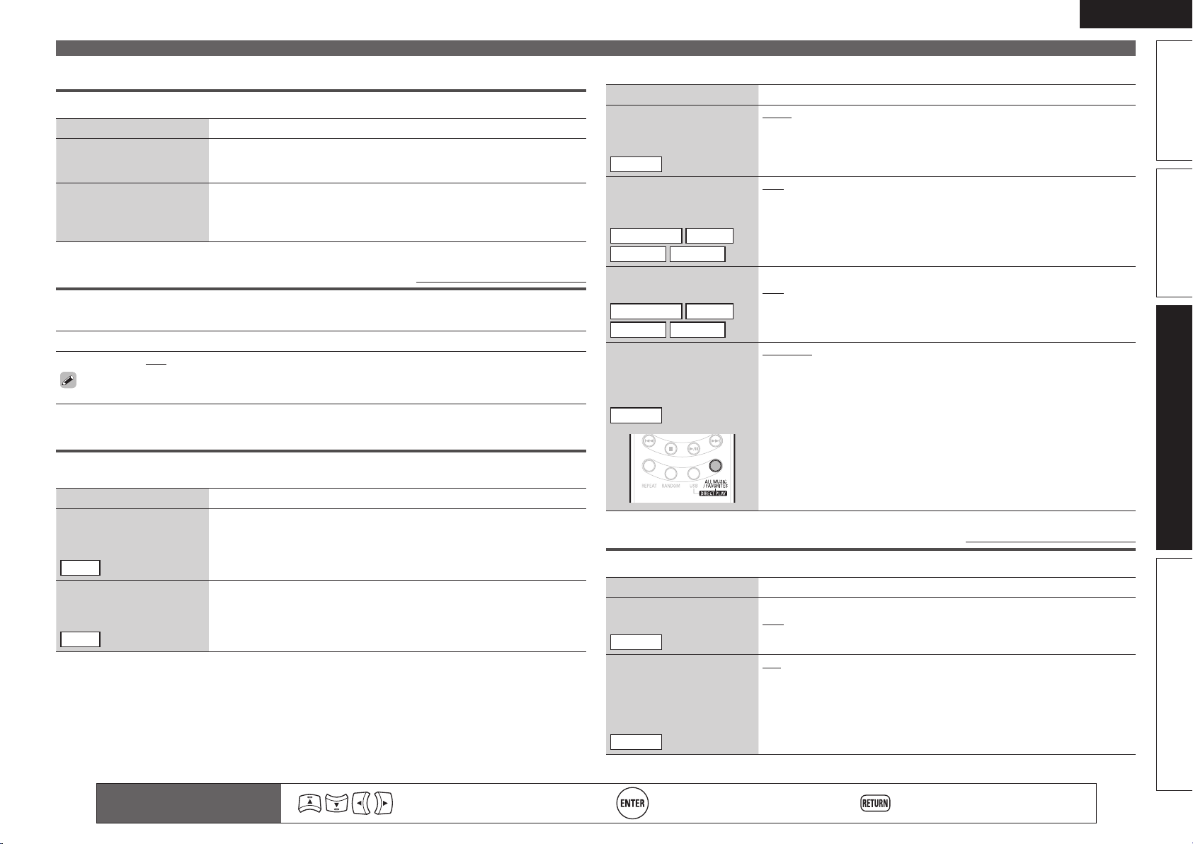
85
Basic versionSimple version Information
ENGLISH
Advanced version
SOURCE SELECT
n Input source : “NET/USB”
Setting items Setting details
USB Select
Set the USB port to be
used.
NET/USB
Front : Select front-panel port.
Rear : Select rear-panel port.
Repeat
Make settings for repeat
mode.
Media Server
Napster
Rhapsody
USB/iPod
OFF : Repeat playback mode is canceled.
All : All files are played repeatedly (All files in a Folder or an album are
played repeatedly).
One : A file being played is played repeatedly.
Random
Make random mode settings.
Media Server
Napster
Rhapsody
USB/iPod
ON : Enable random playback.
OFF : Disable random playback.
Direct Play
Set the
DIRECT PLAY button
function of the sub remote
control unit.
NET/USB
Favorites : Play songs registered as “Favorites”.
All Music : Play the songs saved on the PC media.
Still Picture Default settings are underlined.
Make settings for playing back still picture images.
Setting items Setting details
Slide Show
Make slide show settings.
NET/USB
ON : Display still picture images in a slide show.
OFF : The slide show is not played back.
Interval
Set the time for displaying a
single image when playing
back images in the slide
show.
NET/USB
+5s – +60s
Remote control operation
buttons
Move the cursor
(Up/Down/Left/Right)
Confirm the setting Return to previous menu
Rename
Change the display name of the selected input source.
Setting items Setting details
Rename
Change the display name of
the selected input source.
• Up to eight characters can be input.
• For character input, see page 78.
Default
The input source name
is returned to the default
setting.
Yes : Reset to the defaults.
No : Do not reset to the defaults.
Source Level (Audio) Default settings are underlined.
• This function corrects the playback level of the selected input source’s audio input.
• Make this setting if there are differences in the input volume levels between the different sources.
Setting details
–12dB – +12dB (0dB)
The analog input level and digital input level can be adjusted independently for input sources for
which “HDMI” or “DIGITAL” is assigned at “Input Assign“ (vpage82).
Playback Mode
n Input source : “DOCK”
Setting items Setting details
Repeat
Make settings for repeat
mode.
DOCK
OFF : Repeat playback mode is canceled.
All : All files are played repeatedly.
One : A file being played is played repeatedly.
Shuffle
Make settings for shuffle
mode.
DOCK
OFF : Shuffle playback mode is canceled.
Songs : Shuffle songs.
Albums : Shuffle albums.
1.AVRA100E3_ENG_1st_0824.indd 85 2010/08/26 17:48:13
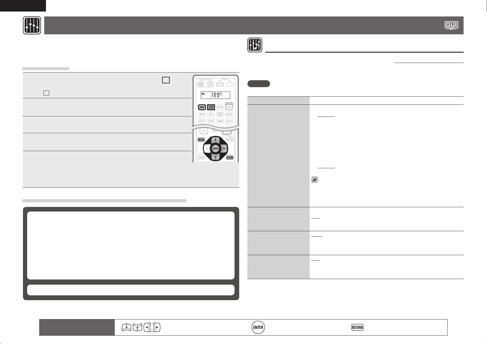
86
ENGLISH
AUDIO/VIDEO ADJUST
The sound being played in the surround mode can be adjusted to your liking.
The items (parameters) that can be adjusted depend on the signal being input and the currently set
surround mode. For details on the adjustable parameters, see “Surround modes and parameters”
(vpage126).
Menu operation
1
Press ZONE SELECT to switch the zone mode to
M
(MAIN
ZONE).
The
M
indicator lights.
2
Press AMP to set the remote control unit to AMP-operation
mode.
3
Press MENU.
The menu is displayed on the TV screen.
4
Use ui to select the menu to be set or operated.
5
Press ENTER or p to enter the setting.
• To return to the previous item, press RETURN.
• Exiting the Menu, press MENU while the menu is displayed.
The menu display disappears.
Items that can be set with the “AUDIO ADJUST” procedure
Audio Adjust (vpage86)
n Surround Parameters (vpage86)
n Tone (vpage88)
n Audyssey Settings (vpage89)
n A-DSX Soundstage (vpage90)
n Manual EQ (vpage91)
n Dolby Volume (vpage91)
n RESTORER (vpage92)
n Audio Delay (vpage92)
Picture Adjust (vpage92)
Remote control operation
buttons
Move the cursor
(Up/Down/Left/Right)
Confi rm the setting Return to previous menu
Audio Adjust
n Surround Parameters
Default settings are underlined.
Adjust surround sound parameters. It may not be possible to set this item depending on the input signal
(vpage126 “Surround modes and parameters”).
NOTE
You cannot set the surround parameters in the PURE DIRECT mode.
Setting items Setting details
Mode
Set the play modes for the
different surround modes.
n In the PLgx or PLg mode
Cinema : Surround sound mode optimized for movie sources.
Music : Surround sound mode optimized for music sources.
Game : Surround sound mode optimized for games.
Pro Logic : Dolby Pro Logic playback mode (PLg mode only).
n In the PLgz mode
Height : Dolby PLgz Height playback mode.
n In the DTS NEO:6 mode
Cinema : Surround sound mode optimized for movie sources.
Music : Surround sound mode optimized for music sources.
• When “Surround Parameters” – “PLgz Height” (vpage88) is set to
“ON”, the “Height” mode is set automatically.
• The “Music” mode is also effective for movie sources including a lot of
stereo music.
Cinema EQ
Soften the treble range
of movie soundtracks for
better understanding.
ON : “Cinema EQ” is used.
OFF : “Cinema EQ” is not used.
DRC
Compress dynamic range
(difference between loud
and soft sounds).
Auto : Automatic dynamic range compression on/off control according to
source. This can be set in the Dolby TrueHD mode.
Low / Middle / High : These set the compression level.
OFF : Dynamic range compression always off.
D.COMP
Compress dynamic range
(difference between loud
and soft sounds).
OFF : Turn dynamic range compression off.
Low / Middle / High : These set the compression level.
1.AVRA100E3_ENG_1st_0824.indd 86 2010/08/26 17:48:14
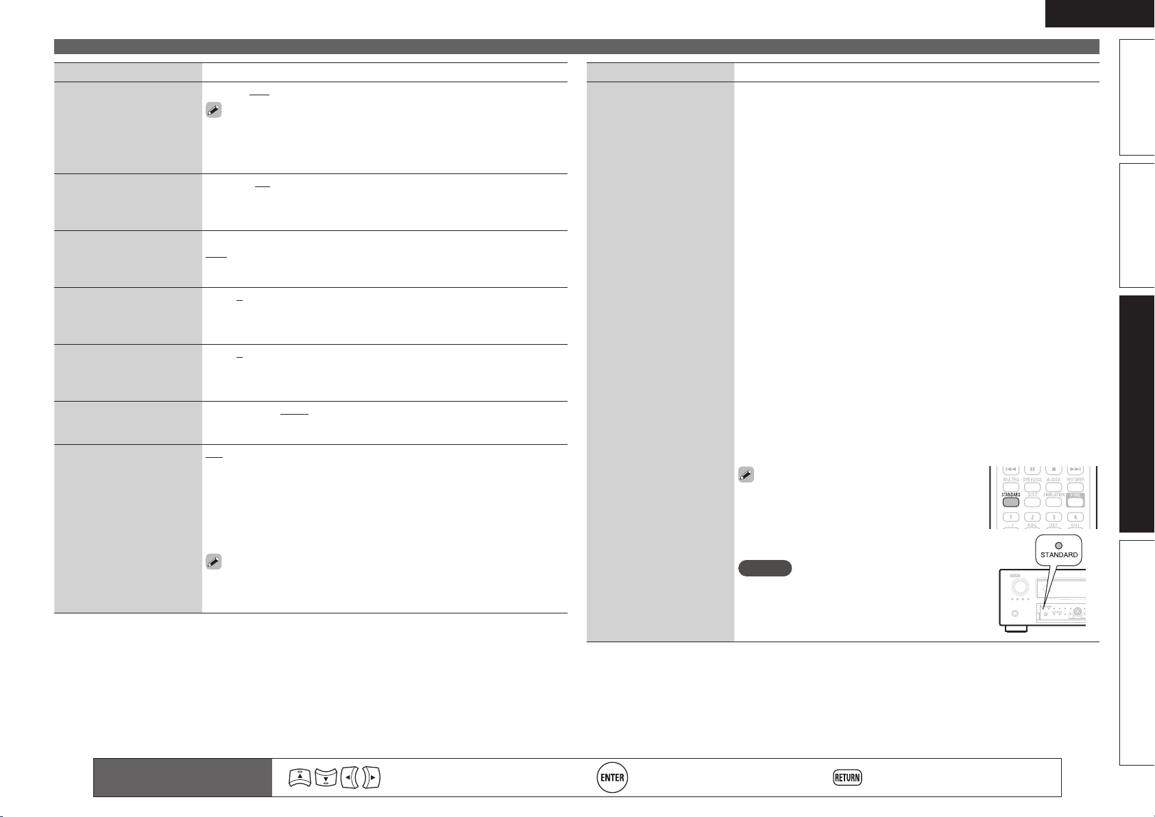
87
Basic versionSimple version Information
ENGLISH
Advanced version
Setting items Setting details
LFE
Adjust the low-frequency
effects level (LFE).
–10dB – 0dB
For proper playback of the different sources, we recommend setting
to the values below.
• Dolby Digital sources : “0dB”
• DTS movie sources : “0dB”
• DTS music sources : “–10dB”
Center Image
Assign center channel
signal to front left and right
channels for wider sound.
0.0 – 1.0 (0.3)
Panorama
Assign front L/R signal also
to surround channels for
wider sound.
ON : Set.
OFF : Do not set.
Dimension
Shift sound image center
to front or rear to adjust
playback balance.
0 – 6 (3)
Center Width
Assign center channel
signal to front left and right
channels for wider sound.
0 – 7 (3)
Delay Time
Adjust delay time to control
sound stage size.
0ms – 300ms (30ms)
AFDM
(Auto flag detect mode)
Detect the source’s
surround back channel
signal and set the
optimum surround mode
automatically.
ON : Set.
OFF : Do not set.
[Example] Playing Dolby Digital software (with EX flag)
• When “AFDM” is set to “ON”, the surround mode is automatically set
to the DOLBY D + PLgx C mode.
• To play in the DOLBY DIGITAL EX mode, set “AFDM” to “OFF” and
“Surround Parameters” – “Surround Back” to “MTRX ON”.
Some Dolby Digital EX sources do not include EX flags. If the playback
mode does not switch automatically even when “AFDM” is set to
“ON”, set “Surround Parameters” – “Surround Back” to “MTRX ON”
or “PLgx CINEMA”.
AUDIO/VIDEO ADJUST
Remote control operation
buttons
Move the cursor
(Up/Down/Left/Right)
Confirm the setting Return to previous menu
Setting items Setting details
Surround Back
Sets the method of
generating of the surround
back channel.
n For 2-channel sources
ON : The surround back channel is used.
OFF : No signal is played from the surround back channels.
n For multi-channel sources
Set the decoding method for the surround back channel.
DSCRT ON : Play the surround back signals included in the 7.1-channel
source.
MTRX ON : Generate and play the surround back channel signals from
the surround channel signals by means of the Dolby Digital EX decoder.
ES DSCRT
z1
: Play the surround back signals included in the
6.1-channel DTS source.
ES MTRX
z2
: Generate and play the surround back channel signals
from the surround channel signals of the DTS source by means of the
DTS-ES decoder.
ON
z3
: Convert the 5.1-channel source of the DTS-HD input signals to
the 7.1-channel output recommended by DTS and then play.
PLgx CINEMA
z4
: Generate and play the surround back signals by
decoding the signals in the Dolby Pro Logic gx Cinema mode.
PLgx MUSIC : Generate and play the surround back signals by
decoding the signals in the Dolby Pro Logic gx Music mode.
OFF : Do not play the surround back channel.
z1 This can be selected when playing DTS sources including a signal to
identify discrete 6.1-channel signals.
z2 This can be selected when playing DTS sources.
z3 This can be selected when playing the 5.1-channel source of DTS-HD.
z4 This can be selected when “Speaker Config.” – “Surround Back”
(vpage96) is set to “2 spkrs”.
• This can also be set by pressing STANDARD.
• If the source being played contains a surround
back signal, the decoder type is automatically
selected by the AFDM function. Set “AFDM” to
“OFF” to switch to your preferred decoder.
NOTE
If the setting in “Speaker Config.” – “Surround
Back” (vpage96) is “None”, “Surround Back” is
not displayed.
1.AVRA100E3_ENG_1st_0824.indd 87 2010/08/26 17:48:14
88
ENGLISH
Remote control operation
buttons
Move the cursor
(Up/Down/Left/Right)
Confirm the setting Return to previous menu
AUDIO/VIDEO ADJUST
Setting items Setting details
Height Gain
Control the front height
channel volume.
Low : Reduce the front height channel volume.
Mid : Front height channel sound is output with standard sound volume.
High : Increase the front height channel volume.
NOTE
“Height Gain” is displayed for the following settings.
• When the “Speaker Config.” – “Front Height” setting (vpage96) is set
other than to “None”.
• When surround mode is “PLgz” or the PLgz decoder is used.
PLgz Height
Determine whether to use
front height channel.
ON : Audio is output from the front height speaker.
OFF : Audio is not output from the front height speaker.
NOTE
• “PLgz Height” is displayed with the settings listed below.
• When the “Speaker Config.” – “Front Height” setting (vpage96) is
set to other than “None”.
• “PLgz Height” cannot be set if the HD Audio source being played
includes a front height channel. In this case, the Front height channel
is played back without decoding in PLgz mode, using the input signal.
Speaker
Make settings for the
speakers outputting sound
when playing back in
DENON original surround
mode.
Height/Wide : Sound is output from the front height speakers and front
wide speakers.
Height : Sound is output from the front height speakers.
Wide : Sound is output from the front wide speakers.
OFF : Sound is not output from the front wide speakers and front height
speakers.
NOTE
Only speakers that are set to something other than “None” in “Speaker
Config.” (vpage95) can be selected.
Subwoofer Att.
Attenuate subwoofer level
when using EXT. IN input.
ON : Set.
OFF : Do not set. Usually use in this mode.
Set this to “ON” if the subwoofer channel level seems too high when
playing audio signal.
Subwoofer
Turn subwoofer output on
and off.
ON : The subwoofer is used.
OFF : The subwoofer is not used.
NOTE
This can be set when the surround mode is “DIRECT” (vpage52) and the
“Subwoofer Mode” (vpage96) is “LFE+Main”.
Effect
Switch effect signal for
multi-surround speakers on
and off.
ON : Create a wider sound stage.
OFF : The effect is not set.
Setting items Setting details
Effect Level
Adjust effect signal level.
1 – 15 (10)
Set to a lower level if the positioning and sense of phase of the
surround signals seems unnatural.
Room Size
Determine size of acoustic
environment.
Medium : Simulate acoustics of a medium room.
Medium-large : Simulate acoustics of a medium-large room.
Large : Simulate acoustics of a large room.
Small : Simulate acoustics of a small room.
Medium-small : Simulate acoustics of a medium-small room.
NOTE
“Room Size” does not indicate the size of the room in which sources are
played.
Default
The “Surround Parameters”
settings are returned to the
default settings.
Yes : Reset to the defaults.
No : Do not reset to the defaults.
n Tone
Adjust the tonal quality of the sound.
Setting items Setting details
Tone Control
Set the tone control function
to ON and OFF.
ON : Allow tone adjustment (bass, treble).
OFF : Playback without tone adjustment.
“Tone Control” can be set when “Dynamic EQ” (vpage 89) and
“Dolby Volume” (vpage91) are set to “OFF”.
NOTE
• “Tone Control” settings are not reflected to ZONE2 and ZONE3.
• The tone cannot be adjusted in the direct mode.
Bass
Adjust low frequency range
(bass).
–6dB – +6dB
“Bass” can be set when “Tone Control” is set to “ON”.
Treble
Adjust high frequency range
(treble).
–6dB – +6dB
“Treble” can be set when “Tone Control” is set to “ON”.
1.AVRA100E3_ENG_1st_0824.indd 88 2010/08/26 17:48:14
89
Basic versionSimple version Information
ENGLISH
Advanced version
Remote control operation
buttons
Move the cursor
(Up/Down/Left/Right)
Confirm the setting Return to previous menu
AUDIO/VIDEO ADJUST
n Audyssey Settings
Default settings are underlined.
Set MultEQ
®
XT 32, Dynamic EQ
®
and Dynamic Volume
®
. These can be selected after Audyssey
®
Auto Setup has been performed. For additional information on Audyssey technology, please see page 132.
NOTE
If you have not performed Auto Setup, or if you change the speaker settings after performing Auto Setup,
you may not be able to select Dynamic EQ/Dynamic Volume, and “Run Audyssey” may be displayed.
In this case, either perform Audyssey Auto Setup over again or perform “Restore” (vpage12) to return to
the settings after Audyssey Auto Setup was run.
Setting items Setting details
MultEQ XT 32
Select one equalizer from
three modes. MultEQ XT 32
corrects both time and
frequency response
problems in the listening
area based on Audyssey
Auto Setup calibration. We
recommend “Audyssey”.
MultEQ XT 32 is the
prerequisite function for
Dynamic EQ and Dynamic
Volume.
OFF : Turn “MultEQ XT 32” equalizer off.
Audyssey : Optimize the frequency response of all speakers.
Audyssey Byp.L/R : Optimize frequency response of speakers except
front L and R speakers.
Audyssey Flat : Optimize frequency response of all speakers to flat
response.
Manual : Apply frequency response set with “Manual EQ” (vpage91).
• “Audyssey”, “Audyssey Byp. L/R” and “Audyssey Flat” can be
selected after Audyssey Auto Setup has been performed. “Audyssey”
is automatically selected after performing Audyssey Auto Setup. When
“Audyssey”, “Audyssey Byp. L/R” or “Audyssey Flat” is selected,
illuminates.
• After running Audyssey Auto Setup, if the
Speaker Configuration, Distance, Channel
Level, and Crossover Frequency have changed
without increasing the number of speakers
measured, only
illuminates.
• Pressing MULTEQ makes this setting.
NOTE
• “MultEQ XT 32” and “Manual” cannot be selected when “EQ
Customize” is set to “Not Used” (vpage100).
• When using headphones, “MultEQ XT 32” is automatically set to “OFF”.
“MultEQ XT 32”, “Dynamic EQ” and “Dynamic Volume” settings are stored for each input source.
Setting items Setting details
Dynamic EQ
Solve the problem of
deteriorating sound quality
as volume is decreased
by taking into account
human perception and
room acoustics. Works with
MultEQ XT 32.
ON : Use Dynamic EQ.
OFF : Do not use Dynamic EQ.
• or is displayed when set to “ON”.
• Buttons on the remote control unit or main unit
can be used for operations.
Press DYN EQ/VOL.
Each time DYN EQ/VOL is pressed, the setting is
changed as shown below.
Dynamic EQ : ON
Dynamic Volume : Midnight
Dynamic EQ : ON
Dynamic Volume : Evening
Dynamic EQ : ON
Dynamic Volume : OFF
Dynamic EQ : OFF
Dynamic Volume : OFF
Dynamic EQ : ON
Dynamic Volume : Day
Reference Level Offset
Audyssey Dynamic EQ is
referenced to the standard
film mix level. It makes
adjustments to maintain
the reference response
and surround envelopment
when the volume is turned
down from 0 dB. However,
film reference level is not
always used in music or
other non-film content.
Dynamic EQ Reference
Level Offset provides three
offsets from the film level
reference (5 dB, 10 dB, and
15 dB) that can be selected
when the mix level of the
content is not within the
standard.
0dB (Film Ref) : This is the default setting and should be used when
listening to movies.
5dB : Select this setting for content that has a very wide dynamic range,
such as classical music.
10dB : Select this setting for jazz or other music that has a wider dynamic
range. This setting should also be selected for TV content as that is usually
mixed at 10 dB below film reference.
15dB : Select this setting for pop/rock music or other program material
that is mixed at very high listening levels and has a compressed dynamic
range.
Setting is enabled when “Dynamic EQ” is “ON” (vpage89).
1.AVRA100E3_ENG_1st_0824.indd 89 2010/08/26 17:48:15
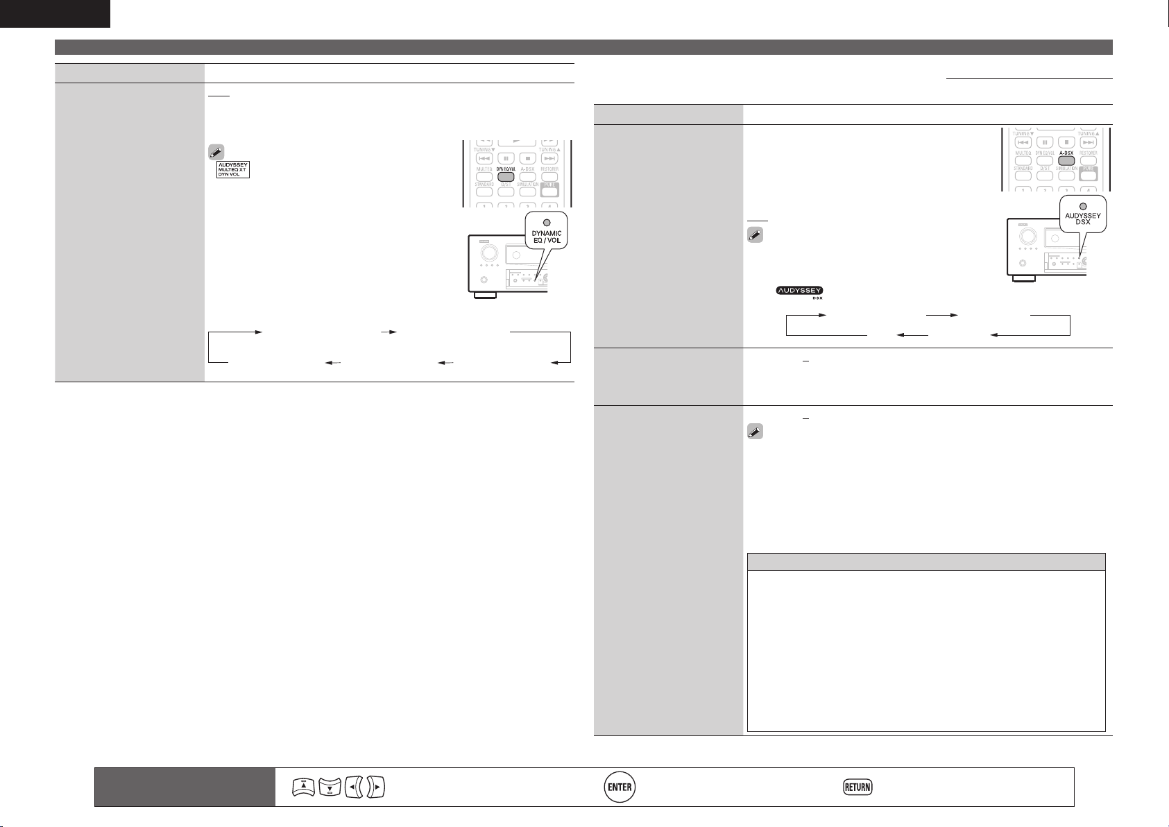
90
ENGLISH
AUDIO/VIDEO ADJUST
Remote control operation
buttons
Move the cursor
(Up/Down/Left/Right)
Confirm the setting Return to previous menu
Setting items Setting details
Dynamic Volume
®
Solve the problem of large
variations in volume level
between TV, movies and
other content (between
quiet passages and
loud passages, etc.) by
automatically adjusting to
the user’s preferred volume
setting.
OFF : Do not use “Dynamic Volume”.
Midnight : Most adjustment to softest and loudest sounds.
Evening : Medium adjustment to loudest and softest sound.
Day : Least adjustment to loudest and softest sounds.
•
is displayed when set to “Midnight”,
“Evening” or “Day”.
• If “Dynamic Volume” is set to “Yes” in Auto
Setup (vpage10), the setting is automatically
changed to “Evening”.
• Buttons on the remote control unit or main unit
can be used for operations.
Press DYN EQ/VOL.
Each time DYN EQ/VOL is pressed, the setting is
changed as shown below.
Dynamic EQ : ON
Dynamic Volume : Midnight
Dynamic EQ : ON
Dynamic Volume : Evening
Dynamic EQ : ON
Dynamic Volume : OFF
Dynamic EQ : OFF
Dynamic Volume : OFF
Dynamic EQ : ON
Dynamic Volume : Day
n A-DSX Soundstage
Default settings are underlined.
Adjust Audyssey DSX™ setting and sound stage parameters.
Setting items Setting details
Audyssey DSX
Provides more immersive
surround sound by adding
the new channels.
ON–Height/Wide– : Turn on A-DSX processing for
height and wide expansion.
ON–Height– : Turn on A-DSX processing for
height expansion.
ON–Wide– : Turn on A-DSX processing for wide
expansion.
OFF : Do not set Audyssey DSX.
• This can also be set by pressing A-DSX on the
remote control unit or press AUDYSSEY DSX on
the main unit.
• The indicator illuminates on the display.
ON -Height/Wide- ON -Height-
OFF ON -Wide-
Stage Width
Adjust sound stage width
when using front wide
speakers.
–10 – +10 (0)
Stage Height
Adjust sound stage height
when using front height
speakers.
–10 – +10 (0)
• “Audyssey DSX” can be set when you are using front height speakers
or front wide speakers.
• “Audyssey DSX” is only valid when using a center speaker.
• “Audyssey DSX” is valid when surround mode is STANDARD mode
other than PLgz Height.
• “A-DSX Soundstage” cannot be configured if the HD Audio source being
played includes Front height and Front wide channels. In this case, the
respective channels are played back using the input signals.
About Audyssey Dynamic Surround Expansion (A-DSX)
Audyssey DSX is a scalable surround expansion system that adds
new channels to improve the surround impression. Based on research
in human hearing Audyssey DSX adds a pair of Wide channels in the
front because that information is critical in the rendering of a realistic
soundstage.
Audyssey DSX then adds a pair of Height channels above the main
front channels to reproduce the next most important acoustical and
perceptual cues related to soundstage depth. In addition to creating
these new channels, Audyssey DSX applies Surround Envelopment
Processing to enhance the blend between the front and side/back
surround channels. The result is a much more seamless and enveloping
home theater experience.
1.AVRA100E3_ENG_1st_0824.indd 90 2010/08/26 17:48:16
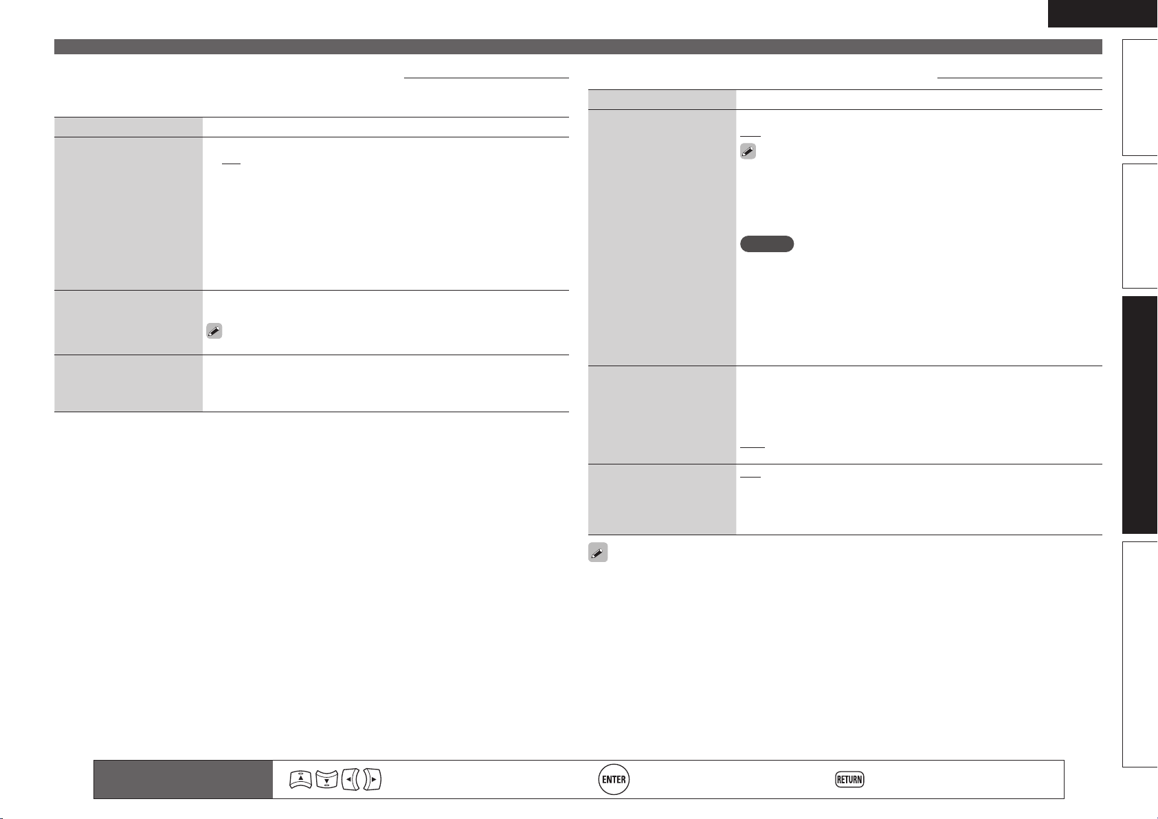
91
Basic versionSimple version Information
ENGLISH
Advanced version
AUDIO/VIDEO ADJUST
Remote control operation
buttons
Move the cursor
(Up/Down/Left/Right)
Confirm the setting Return to previous menu
n Manual EQ
Default settings are underlined.
Use the graphic equalizer to adjust the tone of each speaker.
“Manual EQ” can be set when “MultEQ XT 32” setting (vpage89) is “Manual”.
Setting items Setting details
Adjust CH
Correct the tone of each
speaker.
q Select the speaker tone adjustment method.
L/R : Adjust the tone of left and right speakers together.
Each : Adjust the tone of each speaker.
All : Adjust the tone of all speakers together.
w Select the speaker.
e Select the adjustment frequency band.
63Hz / 125Hz / 250Hz / 500Hz / 1kHz / 2kHz / 4kHz / 8kHz / 16kHz
• Select the speakers you want to adjust when “L/R” or “Each” is
selected.
r Adjust the level.
–20.0dB – +6.0dB (0.0dB)
Curve Copy
Copy “Audyssey Flat” curve
from MultEQ
®
XT 32.
Yes : Copy.
No : Do not copy.
“Curve Copy” is displayed after Audyssey
®
Auto Setup has been
performed.
Default
The “Manual EQ” settings
are returned to the default
settings.
Yes : Reset to the defaults.
No : Do not reset to the defaults.
n Dolby Volume
Default settings are underlined.
Setting items Setting details
Dolby Volume
Automatically adjusts
the volume that varies
depending on the contents
and input source and
performs appropriate
corrections of the frequency
characteristic.
ON : Enables the Dolby Volume function.
OFF : Disables the Dolby Volume function.
• Store “Dolby Volume” for each source.
• When “Dolby Volume” is set to “ON”, you cannot set “Tone”,
“D.COMP”, “DRC” (vpage86, 88).
• When “Dolby Volume” is set to “ON”, “MultEQ XT 32” (vpage89) is
automatically set to “OFF”.
NOTE
• If the playback level of a source you are listening to is high, the data
compression volume will become higher when the Dolby Volume
function is enabled.
When you set “Dolby Volume” to “ON” from “OFF”, the original
playback level is restored. It is recommended that you lower the volume
once before changing the setting.
• The Dolby Volume function cannot be used in the DIRECT or PURE
DIRECT mode.
Volume Leveler
Adjusts the volume so that
the playback level between
different contents will be
always constant.
Low : Set the adjustment volume to the lowest level. Adjusts the volume
of contents with extremely high and low volume to a constant volume.
Mid : Set the adjustment volume to the medium level. Adjusts the volume
of contents with higher and lower volume than the average volume to a
constant volume.
High : Set the adjustment volume to the highest level. Adjusts the volume
of all contents to a constant volume.
Volume Modeler
Perform volume correction
for each frequency band.
Half : Corrects the frequency to a flat level to make listening easier for
playback with low volume.
Full : Corrects the frequency to a flat level to make listening easier at all
times.
OFF : Disables the Volume Modeler function.
“Dolby Volume” settings are stored for each input source.
1.AVRA100E3_ENG_1st_0824.indd 91 2010/08/26 17:48:16
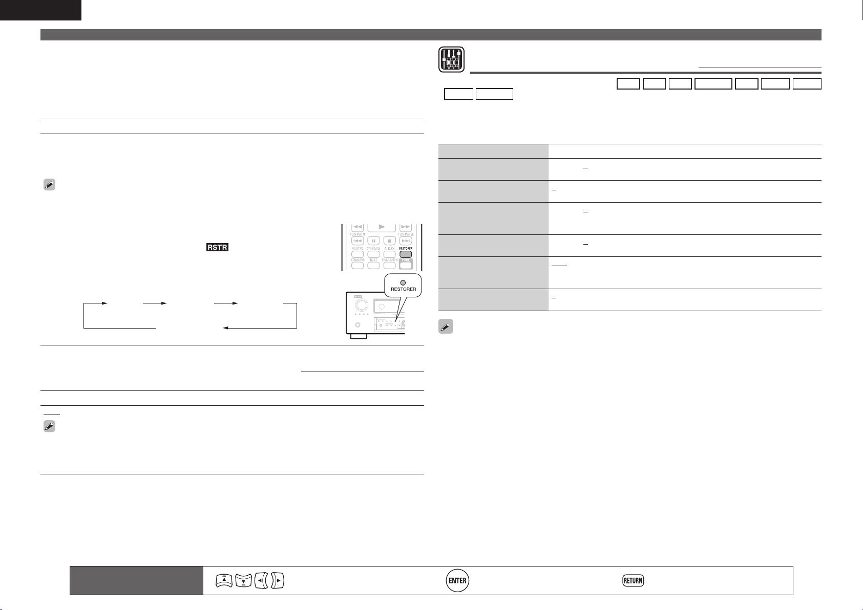
92
ENGLISH
Remote control operation
buttons
Move the cursor
(Up/Down/Left/Right)
Confi rm the setting Return to previous menu
AUDIO/VIDEO ADJUST
n RESTORER
Compressed audio formats such as MP3, WMA (Windows Media Audio) and MPEG-4 AAC reduce
the amount of data by eliminating signal components that are hard for the human ear to hear. The
RESTORER function generates the signals eliminated upon compression, restoring the sound to
conditions near those of the original sound before compression. It also corrects the sense of volume of
the bass to obtain richer sound with compressed audio signals.
Setting details
OFF : Do not use RESTORER.
Mode1 (RESTORER 64) : Optimized mode for compressed sources with very weak highs.
Mode2 (RESTORER 96) : Apply suitable bass and treble boost for all compressed sources.
Mode3 (RESTORER HQ) : Optimized mode for compressed sources with normal highs.
• This item can be set with analog signals or PCM signal (fs = 44.1/48 kHz) is
input.
• “RESTORER” settings are stored for each input source.
• This item default setting for “iPod” and “NET/USB” is “Mode3”. All others are
set to “OFF”.
• When set to something other than “OFF”, is displayed.
• Pressing RESTORER on the remote control unit or the main unit makes this
setting.
• This cannot be set when the surround mode is set to “DIRECT” or “PURE
DIRECT”.
OFF Mode 1
(RESTORER 64)
Mode 2
(RESTORER 96)
Mode 3
(RESTORER HQ)
n Audio Delay
Default settings are underlined.
While viewing video, manually adjust the time to delay audio output.
Setting details
0ms – 200ms
• This item can be set within the range of 0 to 100 ms when “Auto Lip Sync” is set to “ON” and when
a TV compatible with Auto Lip Sync is connected.
• Store “Audio Delay” for each input source.
• Audio Delay for game mode can be set when “Video Mode” (vpage83) is set to “Auto” or “Game”.
Picture Adjust
Default settings are underlined.
• This item
can be set when the input source is
BD
DVD
TV
SAT/CBL
DVR
GAME
V.AUX
DOCK
NET/USB
.
• With input sources other than the ones above, this item can be set when “Video Select” is selected. In
this case, the original input source settings are called out.
• Can be set when the “Video Convert” setting (vpage83) is “ON”.
• “TV” or “GAME” can be set when “HDMI” (vpage82) or “COMP” (vpage83) has been assigned.
Setting items Setting details
Contrast
Adjust picture contrast.
–6 – +6 (0)
Brightness
Adjust picture brightness.
0 – +12
Chroma Level
Adjust picture chroma level
(saturation).
–6 – +6 (0)
Hue
Adjust color hue.
–6 – +6 (0)
DNR
Reduce overall picture
noise.
OFF / Low / Middle / High
Enhancer
Emphasize picture contours.
0 – +12
• “DNR” and “Enhancer” are each effective with HDMI output.
• The value set at “Picture Adjust” is stored in the memory individually for each input source.
1.AVRA100E3_ENG_1st_0824.indd 92 2010/08/26 17:48:16
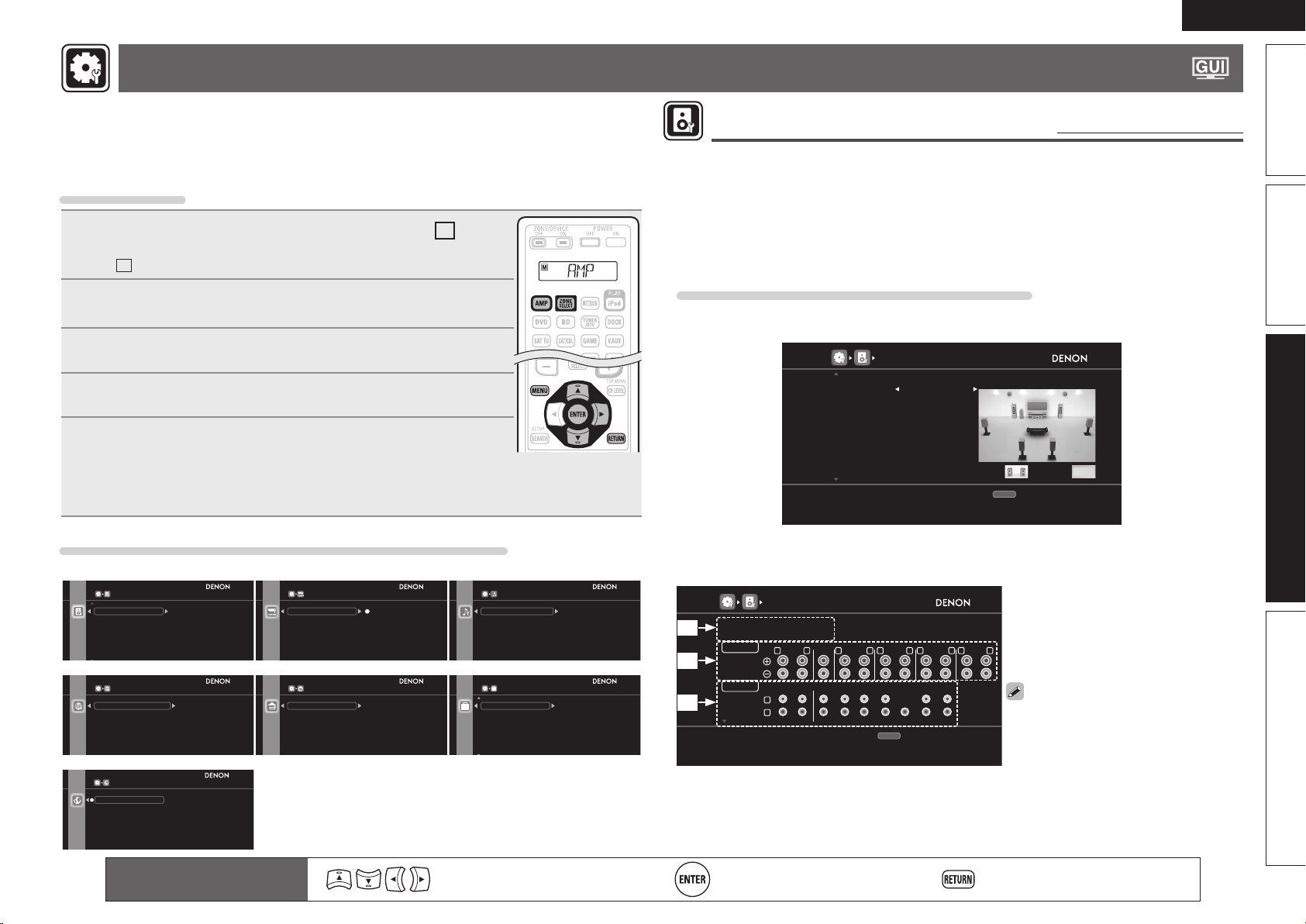
93
Basic versionSimple version Information
ENGLISH
Advanced version
MANUAL SETUP
Set when changing Audyssey
®
Auto Setup settings, or when changing the audio, video, display
or other settings.
• If you change the speaker settings after performing Audyssey Auto Setup, it will not be possible
to set MultEQ
®
XT 32, Dynamic EQ
®
and Dynamic Volume
®
(vpage89, 90).
• Can be used without changing the settings. Please set if necessary.
Menu operation
1
Press ZONE SELECT to switch the zone mode to
M
(MAIN
ZONE).
The
M
indicator lights.
2
Press AMP to set the remote control unit to AMP-operation
mode.
3
Press MENU.
The menu is displayed on the TV screen.
4
Press ui to select the menu to be set or operated.
5
Press ENTER or p to enter the setting.
• To return to the previous item, press RETURN.
• Exiting the Menu, press MENU while the menu is displayed.
The menu display disappears.
Items that can be set with the “MANUAL SETUP” procedure
SPEAKER SETUP
Change assigned power amp settings to match
the speaker system configuration
Amp Assign
Speaker Config.
Bass Setting
Distance
Channel Level
Crossover Freq.
HDMI SETUP
Make settings for RGB output range
RGB Range
Vertical Stretch
Normal
Enhanced
Auto Lip Sync
HDMI Audio Out
Monitor Out
HDMI Control
AUDIO SETUP
Setup playback method for analog signals
inputted from external input connectors (EXT.IN)
EXT.IN Setup
2ch Direct/Stereo
Auto Surround Mode
EQ Customize
Subwoofer Level
ZONE SETUP
Make settings for audio playback in a ZONE 2
system
ZONE2
ZONE3
Bass
Treble
HPF
Lch Level
Rch Level
Channel
NETWORK SETUP
Make settings for wired LAN
Network Connecting
Other
Rhapsody Account
Napster Account
Network Info
OPTION SETUP
Make settings for volume control
Volume Control
Source Delete
GUI
Remote Preset Codes
Quick Select Name
Zone Rename
Volume Display
Volume Limit
Power On Level
Mute Level
OPTION
OPTION
Speaker Setup (vpage93)
Zone Setup (vpage103)Network Setup (vpage101) Option Setup (vpage104)
HDMI Setup (vpage98) Audio Setup (vpage99)
LANGUAGE
Select the language displayed on the GUI screen
English
Français
Enter
Language (vpage106)
Remote control operation
buttons
Move the cursor
(Up/Down/Left/Right)
Confi rm the setting Return to previous menu
Speaker Setup
Default settings are underlined.
Perform when setting the speakers manually or when changing settings made in Audyssey Auto Setup.
• If you change the speaker settings after performing Audyssey Auto Setup, it will not be possible to select
MultEQ XT 32, Dynamic EQ and Dynamic Volume (vpage89, 90).
• MANUAL SETUP can be used without changing the settings. Please set if necessary.
n Change power amp assignment to suit the speaker system confi guration
(Amp Assign)
Examples of Amp Assign menu screen displays
[1st page]
Set items referring to “Steps for setting “Amp Assign”” (vpage94).
[1/2]
AMP ASSIGN
RETURN
Assign power amp to ZONE2 stereo signal
Return
Assign Sp. F.WIDE
Assign Mode ZONE2
ZONE2: ZONE3:
[2nd page]
• The signal being output by each speaker can change according to “Amp Assign” setting.
• The speaker terminals and the output from the pre-out terminals can be checked on this screen.
[2/2]
AMP ASSIGN
RETURN
Check signal output from speaker/PREOUT connectors
Return
Assign Sp. F.WIDE
Assign Mode ZONE2
SPEAKERS
ZONE2
FRONT CENTER
ZONE3 FR SW1 SR SW2 FHR WR
FL C SL FHL WL
L
R
R L
SURROUND
R L
SURR.BACK
R L
F.HEIGHT
R L
ZONE2
R L
PRE OUT
q Current settings
w Signal being output from speaker
terminal
e Output from pre-out terminal
• Terminals not being used are greyed
out.
See also page 5, 6, 56 – 62 for how to
connect the speakers.
q
w
e
1.AVRA100E3_ENG_1st_0824.indd 93 2010/08/26 17:48:17
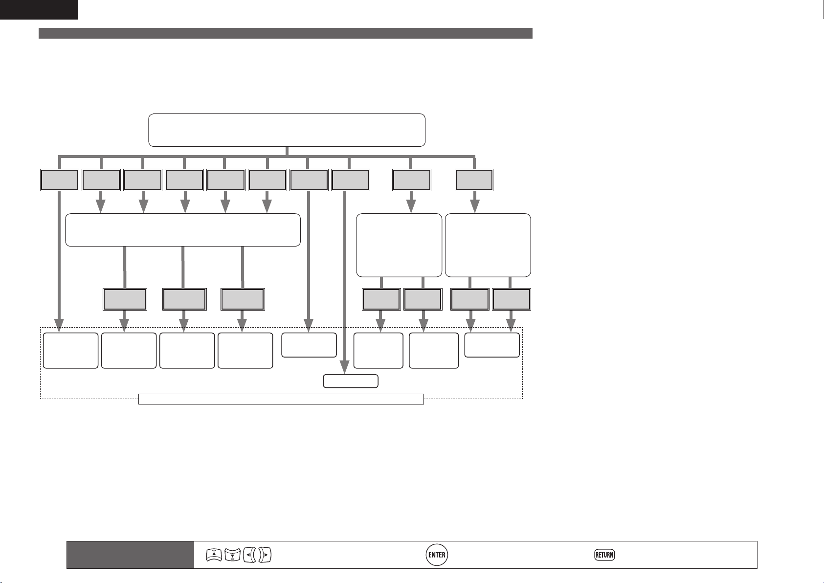
94
ENGLISH
n Steps for setting “Amp Assign”
This unit is provided with ten types of Assign Mode settings.
You can switch the channels assigned to a power amplifier in accordance with your speaker system or perform playback using up to 11
channels using a combination of the built-in power amplifier for 9-channel and an external power amplifier for 2-channel. You can also use
this unit as a preamplifier.
Use the following flowchart to set the speaker system of this unit.
“Assign Mode” settings
Select the method for using a power amplifier in accordance with your
speaker system (vpage95 – [1]).
NORMAL ZONE2
Z2/3-
MONO
Bi-AMP 2CH Front B
2CH Bi-
AMP
ZONE2/3 11CH
PRE
AMP
“Assign Sp.” settings
Select the speaker terminal from which to output the signals
assigned to the power amplifier (vpage95 – [2]).
“Ext. Amp”
settings
Select a channel that
uses the PRE OUT
connector (vpage95
– [3]).
“Assign Sp.”
settings
Set whether or not
to use the speaker
terminals for multizone
(vpage95 – [4]).
S.BACK F.HEIGHT F.WIDE Height Front None ZONE2/3
9.2ch
(5.2 + SB + FH)
(5.2 + SB + FW)
7.2ch
(5.2 + FH)
(5.2 + FW)
7.2ch
(5.2 + SB)
(5.2 + FW)
7.2ch
(5.2 + SB)
(5.2 + FH)
7.2ch
(5.2 + SB)
5.2ch
11.2ch
(9.2 + Height
(PRE OUT))
11.2ch
(PRE OUT)
Maximum number of channels that can be used for the MAIN ZONE audio
11.2ch
(9.2 + Front
(PRE OUT))
MANUAL SETUP
Remote control operation
buttons
Move the cursor
(Up/Down/Left/Right)
Confirm the setting Return to previous menu
1.AVRA100E3_ENG_1st_0824.indd 94 2010/08/26 17:48:17
95
Basic versionSimple version Information
ENGLISH
Advanced version
Setting items Setting details
Amp Assign
Change the power
amp assignment to suit
the speaker system
configuration.
[1] Assign Mode : Select the method for using a power amplifier in
accordance with your speaker system.
• NORMAL : Select the NORMAL setting to perform 7.2-channel or
9.2-channel playback using the surround back, front height, or front
wide speakers. The surround back, front height, and front wide
speakers are automatically switched in accordance with the surround
mode or input signals.
• ZONE2 : Select the ZONE 2 setting to assign the unit’s built-in power
amplifier for ZONE2 and output the audio in stereo.
• ZONE2/3 : Select the ZONE 2/3 setting to assign the unit’s built-in
power amplifier for ZONE2 and ZONE3 and output the audio in stereo.
• Z2/3-MONO : Select the ZONE 2/3-MONO setting to assign the unit’s
built-in power amplifier for ZONE2 and ZONE3 and output the audio in
monaural.
• Bi-AMP : Select the Bi-AMP setting to connect the front speakers via
the bi-amp connection.
• 2CH : When you perform 2-channel playback in the DIRECT or STEREO
mode, select the 2CH setting to use the other front speakers for
playback.
• 2CH Bi-AMP : When you perform 2-channel playback in the DIRECT or
STEREO mode, select the 2CH Bi-AMP setting to use the other front
speakers for Bi-Amp playback.
• Front B : Select the Front B setting to use the second set of front
speakers for playback. You can switch the front speakers A and B to be
used for playback in accordance with the 2-channel playback or multi-
channel playback mode. When you select this Front B setting, also
perform the “Front Speaker Setup” (vpage98) procedure.
• 11CH : Select the 11CH setting to perform playback using up to 11.2
channels using a combination of the unit’s built-in power amplifier for
9-channel and an external power amplifier for 2-channel.
• PRE AMP : Select the PRE AMP setting to use this unit as a preamplifier
by connecting all speakers to an external power amplifier. You can
perform up to 11.2-channel playback. When you use the PRE AMP
mode, the built-in power amplifier operation of this unit is stopped, and
interference to the preamplifier from the power amplifier is reduced.
MANUAL SETUP
Remote control operation
buttons
Move the cursor
(Up/Down/Left/Right)
Confirm the setting Return to previous menu
Setting items Setting details
Amp Assign
(Continued)
n When you set “Assign Mode” to “ZONE2”, “ZONE2/3-MONO”,
“Bi-AMP”, “2CH” or “Front B”, perform the following setting.
[2] Assign Sp. : Select a speaker for audio output assigned by “Assign
Mode”.
• S.BACK : Select the S.BACK setting to output the assigned audio from
the surround back speakers.
• F.HEIGHT : Select the F.HEIGHT setting to output the assigned audio
from the front height speakers.
• F.WIDE : Select the F.WIDE setting to output the assigned audio from
the front wide speakers.
n When you set “Assign Mode” to “11CH”, perform the following
setting.
[3] Ext. Amp : Select the PRE OUT connector to which an external power
amplifier is connected.
• Height : Select when you perform playback by connecting an external
power amplifier to the front height channel of the PRE OUT connector.
• Front : Select when you perform playback by connecting an external
power amplifier to the front channel of PRE OUT connector.
n When you set “Assign Mode” to “PRE AMP”, perform the following
setting.
[4] Assign Sp. : Set whether or not to use the speaker terminals for
multizone.
• None : The speaker terminals of this unit are not used for multizone.
• ZONE2/3 : Use the speaker terminals of this unit for multizone.
When ZONE2/3 is set, ZONE2 audio is output from the SURR.BACK/
AMP ASSIGN speaker terminals and ZONE3 audio is output from the
F.WIDE/AMP ASSIGN speaker terminals.
Speaker Config.
Select speaker configuration
and size (bass reproduction
capability).
NOTE
Do not use the outward
shape of the speaker to
determine selection of a
“Large” or “Small” speaker.
Instead, use the frequencies
set in “Crossover Freq.”
(vpage98) as the standard
for determining bass
reproduction capability.
Front : Set the front speaker size.
• Large : Use a large speaker that can adequately play back low
frequencies.
• Small : Use a small speaker that has inadequate playback capacity for
low frequencies.
• When “Subwoofer” is set to “None”, “Front” is automatically set to
“Large”.
• When “Front” is set to “Small”, “Center”, “Surround“, “Surround
Back”, “Front Height” and “Front Wide” can not be set to “Large”.
1.AVRA100E3_ENG_1st_0824.indd 95 2010/08/26 17:48:18
96
ENGLISH
MANUAL SETUP
Remote control operation
buttons
Move the cursor
(Up/Down/Left/Right)
Confirm the setting Return to previous menu
Setting items Setting details
Speaker Config.
(Continued)
Center : Set the presence and size of the center speaker.
• Large : Use a large speaker that can adequately play back low
frequencies.
• Small : Use a small speaker that has inadequate playback capacity for
low frequencies.
• None : Select when a center speaker is not connected.
“Large” is not displayed when “Front” is set to “Small”.
Subwoofer : Set the presence of a subwoofer.
• 2 spkrs : Two subwoofers are used.
• 1 spkr : One subwoofer is used.
• None : Select when a subwoofer is not connected.
When “Front” is set to “Small”, “Subwoofer” is automatically set to
“1 spkr” or “2 spkrs”.
Surround : Set the presence and size of the surround speakers.
• Large : Use a large speaker that can adequately play back low
frequencies.
• Small : Use a small speaker that has inadequate playback capacity for
low frequencies.
• None : Select when the surround speakers are not connected.
• When “Surround” is set to “Large”, “Surround Back”, “Front Height”
and “Front Wide” can be set to “Large”.
• When “Surround” is set to “None”, “Surround Back”, “Front Height”
and “Front Wide” are automatically set to “None”.
Surround Back : Set the presence, size and number of surround back
speakers.
• Large : Use a large speaker that can adequately play back low
frequencies.
• Small : Use a small speaker that has inadequate playback capacity for
low frequencies.
• None : Select when the surround back speakers are not connected.
• 2 spkrs : Use two surround back speakers.
• 1 spkr : Use only one surround back speaker. When you select this
setting, connect the surround back speaker to the left (L) channel.
Even when the “Surround Back“ setting is other than “None”, sound
may not be emitted from the surround back speaker, depending on
the playback source. In this case, make “Surround Parameters” –
“Surround Back” setting other than “OFF” (vpage87).
NOTE
“Surround Back” cannot be set when “Amp Assign” – “Assign Mode”
(vpage95) is set to “ZONE2/3” or when “Assign Sp.” is set to “S.BACK”.
Setting items Setting details
Speaker Config.
(Continued)
Front Height : Set the presence and size of the front height speakers.
• Large : Use a large speaker that can adequately play back low
frequencies.
• Small : Use a small speaker that has inadequate playback capacity for
low frequencies.
• None : Select when the front height speakers are not connected.
NOTE
“Front Height” cannot be set when “Amp Assign” – “Assign Mode”
(vpage95) is set to “ZONE2/3”, “2CH Bi-AMP” or when “Assign Sp.” is
set to “F.HEIGHT”.
Front Wide : Set the presence and size of the front wide speakers.
• Large : Use a large speaker that can adequately play back low
frequencies.
• Small : Use a small speaker that has inadequate playback capacity for
low frequencies.
• None : Select when the front wide speakers are not connected.
NOTE
“Front Wide” cannot be set when “Amp Assign” – “Assign Mode”
(vpage95) is set to “ZONE2/3”, “2CH Bi-AMP” or when “Assign Sp.” is
set to “F.WIDE”.
Bass Setting
Set subwoofer and LFE
signal range playback.
Subwoofer Mode : Select low range signals to be reproduced by
subwoofer.
• LFE : The low range signal of the channel set to “Small” speaker size is
added to the LFE signal output from the subwoofer.
• LFE+Main : The low range signal of all channels is added to the LFE
signal output from the subwoofer.
• “Subwoofer Mode” can be set when “Speaker Config.” – “Subwoofer”
(vpage96) is set to “1 spkr” or “2 spkrs”.
• Play music or a movie source and select the mode offering the strongest
bass.
• Select “LFE+Main” if you want the bass signals to always be produced
from the subwoofer.
NOTE
If “Front” and “Center” for “Speaker Config.” are set to “Large”, and
“Subwoofer Mode” is set to “LFE”, no sound may be output from the
subwoofers, depending on the input signal or selected surround mode.
LPF for LFE : Set LFE signal playback range.
• 80Hz / 90Hz / 100Hz / 110Hz / 120Hz / 150Hz / 200Hz / 250Hz
1.AVRA100E3_ENG_1st_0824.indd 96 2010/08/26 17:48:18
97
Basic versionSimple version Information
ENGLISH
Advanced version
Remote control operation
buttons
Move the cursor
(Up/Down/Left/Right)
Confirm the setting Return to previous menu
MANUAL SETUP
Setting items Setting details
Distance
Set distance from listening
position to speakers.
Measure beforehand the
distance from the listening
position to each speaker.
Feet / Meters : Set the unit of distance.
Step : Set the minimum variable width of the distance.
• 1ft / 0.1ft
• 0.1m / 0.01m
Default : The “Distance” settings are returned to the default settings.
• Yes : Reset to the defaults.
• No : Do not reset to the defaults.
When you select “Default” and press ENTER, the “Return all settings
to the default?” prompt is displayed. Select either “Yes” or “No”, and
press ENTER.
Front L / Front R / Center / Subwoofer / Subwoofer 1
z1
/ Subwoofer
2
z2
/ Surr.L / Surr.R / Surr.Back L
z2
/ Surr.Back R
z2
/ Front Height
L / Front Height R / Front Wide L / Front Wide R : Select the speaker.
z1 When the “Speaker Config.” – “Subwoofer” setting (vpage96) is
set to “2 spkrs”, “Subwoofer 1” and “Subwoofer 2” are displayed.
z2 When the “Speaker Config.” – “Surround Back” setting (vpage96)
is set to “1 spkr”, “Surround Back” is displayed.
• 0.0ft – 60.0ft / 0.00m – 18.00m : Set the distance.
• The speakers that can be selected differ depending on the “Amp Assign”
(vpage95) and “Speaker Config.” (vpage95) settings.
• Default settings :
Front L / Front R / Center / Subwoofer / Subwoofer 1 / Subwoofer 2 /
Front Height L / Front Height R / Front Wide L / Front Wide R : 12.0 ft
(3.6 m)
Surr. L / Surr. R / Surr.Back L / Surr.Back R : 10.0 ft (3.0 m)
• Set the difference in the distance between the speakers to less than 20
ft (6.0 m).
NOTE
Speakers set to “None” in “Speaker Config.” (vpage 95) are not
displayed.
Setting items Setting details
Channel Level
Set the volume of the test
tone to be the same when it
is output from each speaker.
Test Tone : Output test tone.
• Front L / Front Height L / Center / Front Height R / Front R / Front
Wide R / Surround R / Surr.Back R
z1
/ Surr.Back L
z1
/ Surround
L / Front Wide L / Subwoofer / Subwoofer 1
z2
/ Subwoofer 2
z2
/
Subwoofer 1+2
z2
: Select the speaker.
z1 When the “Speaker Config.” – “Surround Back” setting (vpage96)
is set to “1 spkr”, “Surr.Back” is displayed.
z2 When the “Speaker Config.” – “Subwoofer” setting (vpage96) is
set to “2 spkrs”, “Subwoofer 1”, “Subwoofer 2” and “Subwoofer
1+2” are displayed.
• –12.0dB – +12.0dB (0.0dB) : Adjust the volume.
• After aligning both the distances and levels of subwoofer 1 and
subwoofer 2, please adjust subwoofer 1+2. These parameters affects
the volume of subwoofer 1+2.
• By clicking o p, the volume of both subwoofer 1 and subwoofer 2
moves down or up together.
• If one of subwoofer1 or subwoofer 2 reaches ±12.0 dB, then the cursors
don’t move further.
• When “Channel Level” is adjusted, the adjusted values are set for all the
surround modes. To adjust the channel level separately for the different
surround modes, use the operation see page 66.
NOTE
• Speakers set to “None” in the “Speaker Config.” (vpage95) settings
are not displayed.
• When a headphones jack is inserted in the PHONES jack of this unit, the
“Channel Level” is not displayed.
Default : The “Channel Level” settings are returned to the default settings.
• Yes : Reset to the defaults.
• No : Do not reset to the defaults.
1.AVRA100E3_ENG_1st_0824.indd 97 2010/08/26 17:48:18
98
ENGLISH
Remote control operation
buttons
Move the cursor
(Up/Down/Left/Right)
Confi rm the setting Return to previous menu
MANUAL SETUP
Setting items Setting details
Crossover Freq.
Set the maximum frequency
of the bass signal output
from each channel to
the subwoofer. Set the
Crossover Frequency to
suit the bass reproduction
capability of the speaker
being used.
40Hz / 60Hz / 80Hz / 90Hz / 100Hz / 110Hz / 120Hz / 150Hz / 200Hz /
250Hz : Set the crossover frequency.
Advanced : Specify crossover frequency for each speaker.
• Front / Center / Surround / Surr. Back / Front Height / Front Wide :
Select the speaker.
• 40Hz / 60Hz / 80Hz / 90Hz / 100Hz / 110Hz / 120Hz / 150Hz / 200Hz /
250Hz : Set the crossover frequency.
• “Crossover Freq.” can be set when the “Bass Setting” – “Subwoofer
Mode” (vpage96) setting is “LFE+Main”, or when you have a speaker
that is set to “Small”.
• Always set the crossover frequency to “80Hz”. When using small
speakers, however, we recommend setting the crossover frequency to
a higher frequency.
• For speakers set to “Small”, sound below the crossover frequency
is cut from the sound output. The cut bass sound is output from the
subwoofer or front speakers.
• The speakers that can be set when “Advanced” is selected differ
depending on to the “Subwoofer Mode” setting (vpage96).
• When “LFE” is selected, speakers set to “Small” at “Speaker Confi g.”
can be set. If the speakers are set to “Large”, “Full Band” is displayed
and the setting cannot be made.
• If set to “LFE+Main”, this setting can be made regardless of the
speaker size.
Speaker Impedance
Set the impedance of
connected speakers.
8Ω/ohms : Select when the impedance of the connected speaker is 8 Ω
or more.
6Ω/ohms : Select when the impedance of the connected speaker is at
least 6 Ω but less than 8 Ω.
4Ω/ohms : Select when the impedance of the connected speaker is at
least 4 Ω but less than 8 Ω.
Check the speaker impedance (Ω) shown on the back of your speakers
or in the instruction manual beforehand.
Front Speaker Setup
Set the front speakers to
use for every surround
mode.
NOTE
This can be set when
“Amp Assign” – “Assign
Mode” is set to “Front B”
(vpage95).
2CH DIRECT/STEREO : The front speakers used in the direct, stereo and
pure direct play modes (2 channel) are set in advance.
• A : Front speaker A is used.
• B : Front speaker B is used.
• A+B : Both front speakers A and B are used.
MULTI CH : The front speakers used in modes other than the direct,
stereo and pure direct play modes (2 channel) are set in advance.
• A : Front speaker A is used.
• B : Front speaker B is used.
• A+B : Both front speakers A and B are used.
HDMI Setup
Default settings are underlined.
Make settings for HDMI video/audio output.
Setting items Setting details
RGB Range
Set the video range of RGB
output from the HDMI
connector.
Normal : Output with RGB video range (16 (black) to 235 (white)).
Enhanced : Output with RGB video range (0 (black) to 255 (white)).
This setting is active when using a TV equipped with a DVI terminal.
Vertical Stretch
Expand image signal in
vertical direction.
ON : Expand image signal in vertical direction.
OFF : Do not expand signal in vertical direction.
Auto Lip Sync
Make automatic
compensation for timing
shift in audio and video
output.
ON : Compensated.
OFF : Not compensated.
HDMI Audio Out
Select HDMI audio output
device.
Amp : Play back through speakers connected to the receiver.
TV : Play back through TV connected to the receiver.
When the HDMI control function is activated, priority is given to the TV
audio setting (vpage65 “HDMI control function”).
Monitor Out
Make settings for HDMI
monitor output.
Auto (Dual) : The presence of a TV connected to the MONITOR 1 or
MONITOR 2 terminal is detected automatically, and that TV connection
is used.
Monitor 1 : A TV connected to the MONITOR 1 terminal is always used.
Monitor 2 : A TV connected to the MONITOR 2 terminal is always used.
• If both the Monitor 1 and 2 connectors are connected and “Resolution”
(vpage84) is set to “Auto”, the signals are output with a resolution
compatible with both TV.
• With “Resolution” (vpage84) not set to “Auto”,
check whether the TV you are using is compatible
with the resolution under “HDMI Information” –
“Monitor 1” and “Monitor 2” (vpage107).
• You can also set “Monitor Out” by pressing
MONITOR SELECT.
NOTE
Depending on the monitor you have connected, the display may not
be correct when you set to “Auto (Dual)”. In such a case, set to either
“Monitor 1” or “Monitor 2”.
1.AVRA100E3_ENG_1st_0824.indd 98 2010/08/26 17:48:18
99
Basic versionSimple version Information
ENGLISH
Advanced version
MANUAL SETUP
Remote control operation
buttons
Move the cursor
(Up/Down/Left/Right)
Confi rm the setting Return to previous menu
Setting items Setting details
HDMI Control
You can link operations with
devices connected to HDMI
and compatible with HDMI
Control.
Control : Set the HDMI control function.
• ON : Use HDMI control function.
• OFF : Do not use HDMI control function.
• When a device that is not compatible with the HDMI control function is
connected, set “HDMI Control” – “Control” to “OFF”.
• Please consult the operating instructions for each connected component
to check the settings.
• Refer to “HDMI control function” (vpage65) for more information about
the HDMI control function.
NOTE
• When “HDMI Control” – “Control” is set to “ON”, it consumes more
standby power. If you are not using this unit for an extended period, it
is recommended that you unplug the power cord from the power outlet.
• “HDMI Control” does not work when the power to the equipment is off.
Either turn power on or set to standby.
• The HDMI control function controls operations of a TV that is compatible
with the HDMI control function. Make sure that the TV and HDMI are
connected when you perform HDMI control.
• If the “HDMI Control” – “Control” settings have been changed, always
reset the power to connected devices after the change.
Standby Source : Sets the HDMI input source to put into standby when
the power is on.
• Last : This item is set at the last-used input source.
• HDMI1 / HDMI2 / HDMI3 / HDMI4 / HDMI5 / HDMI6 / HDMI7 : Put the
respective input source into standby.
“Standby Source” can be set when “HDMI Control” – “Control” is set
to “ON”.
Control Monitor : Set the HDMI MONITOR terminal to output the HDMI
control signal.
• Monitor 1 : Output from the MONITOR 1 terminal.
• Monitor 2 : Output from the MONITOR 2 terminal.
• “Control Monitor” can be set when “HDMI Control” – “Control” is set
to “ON”.
• ARC function works only with the terminal selected by “Control
Monitor”.
Setting items Setting details
HDMI Control
(Continued)
Power Off Control : Links the power standby of this unit to external
equipment.
• All : If power to a connected TV is turned off independently of the input
source, power to this unit is automatically set to standby.
• Video : If power to a connected TV is turned off when the input source
is BD / DVD / TV / SAT/CBL / DVR / GAME / V.AUX / DOCK, power to this
unit is automatically set to standby.
• OFF : This unit does not link with power to a TV.
“Power Off Control” can be set when “HDMI Control” – “Control” is
set to “ON”.
Audio Setup
Default settings are underlined.
Make settings for audio playback.
Setting items Setting details
EXT. IN Setup
Setup playback method for
analog signals inputted from
external input connectors
(EXT. IN).
Subwoofer Level : Set playback level of subwoofer signal input from the
external input connector (EXT. IN).
• +15dB : This is the recommended level.
• +10dB / +5dB / 0dB : Select the level according to the player being used.
2ch Direct/Stereo
Select the method for
setting the speakers used
in the 2-channel direct and
stereo playback modes.
Setting : Select the method for setting the speakers used in the 2-channel
direct and stereo playback modes.
• Basic : The settings at “Speaker Setup” (vpage93) are applied.
• Custom : Make separate settings for 2-channel. Make the following
settings:
Front : Set the front speaker size.
• Large : Use a large speaker that can adequately play back low
frequencies.
• Small : Use a small speaker that has inadequate playback capacity for
low frequencies.
If “Speaker Confi g.” – “Subwoofer” (vpage96) is set to “None”, the
setting is automatically set to “Large”.
Subwoofer : Set the presence of a subwoofer.
• Yes : Use a subwoofer.
• No : Select when a subwoofer is not connected.
If “Speaker Confi g.” – “Subwoofer” (vpage96) is set to “None”, the
setting is automatically set to “No”. If the “Front” setting is “Small”,
the setting is automatically “Yes”.
1.AVRA100E3_ENG_1st_0824.indd 99 2010/08/26 17:48:19

100
ENGLISH
Remote control operation
buttons
Move the cursor
(Up/Down/Left/Right)
Confirm the setting Return to previous menu
Setting items Setting details
2ch Direct/Stereo
(Continued)
SW Mode : Select low range signals to be reproduced by subwoofer.
• LFE : When the “2ch Direct/Stereo” – “Front” setting is set to “Large”,
the LFE signal alone is output from the subwoofer. Also, when the “2ch
Direct/Stereo” – “Front” setting is set to “Small”, the front channel low
range signal is added to the LFE signal output from the subwoofer.
• LFE+Main : The front channel low range signal is added to the LFE signal
output from the subwoofer.
This setting can be set made “2ch Direct/Stereo” – “Subwoofer” is
set to “Yes”.
Crossover : Set the maximum frequency of the bass signal output from
each channel to the subwoofer.
• 40Hz / 60Hz / 80Hz / 90Hz / 100Hz / 110Hz / 120Hz / 150Hz / 200Hz /
250Hz
• This setting can be set made “2ch Direct/Stereo” – “Subwoofer” is set
to “Yes”.
• If the “2ch Direct/Stereo” – “Front” setting is “Large” and the
“Subwoofer Mode” setting is “LFE”, “Full Band” is displayed and the
setting cannot be made.
Distance FL / Distance FR : Select the speaker.
• 0.0ft – 60.0ft (12.0ft) / 0.00m – 18.00m (3.60m) : Set the distance to
the speaker.
Set the difference in the distance between the speakers to less than
20 ft (6.0 m).
Level FL / Level FR : Select the speaker.
• –12.0dB – +12.0dB (0.0dB) : Adjust the level of each channel.
Auto Surround Mode
Make setting for
memorizing surround mode
setting for each input signal
type.
ON : Memorize settings. Automatically play with the last used surround
mode.
OFF : Do not memorize settings. Surround mode does not change
according to input signal.
• The auto surround mode function lets you store in the memory the
surround mode last used for playing the four types of input signals listed
below.
q Analog and PCM 2-channel signals
w Dolby Digital and DTS 2-channel signals
e Dolby Digital and DTS multi-channel signals
r LPCM and DSD Multi-channel signals
• When playing in PURE DIRECT, the surround mode does not change
even if the input signal is changed.
MANUAL SETUP
Setting items Setting details
EQ Customize
Set so that unused equalizer
settings are not displayed
when
MULTEQ is pressed.
The equalizer mode in which
“Not Used” is selected
cannot be stored and
recalled in the Quick Select
function.
Audyssey : Set when not using “Audyssey” equalizer.
• Used : Use.
• Not Used : Do not use.
Set so that “Audyssey” settings can be made when Audyssey
®
Auto
Setup is performed.
Audyssey Byp. L/R : Set when not using “Audyssey Byp. L/R” equalizer.
• Used : Use.
• Not Used : Do not use.
Set so that “Audyssey Byp. L/R” settings can be made when
Audyssey Auto Setup is performed.
Audyssey Flat : Set when not using “Audyssey Flat” equalizer.
• Used : Use.
• Not Used : Do not use.
Set so that “Audyssey Flat” settings can be made when Audyssey
Auto Setup is performed.
Manual : Set when not using the “Manual” equalizer.
• Used : Use.
• Not Used : Do not use.
1.AVRA100E3_ENG_1st_0824.indd 100 2010/08/26 17:48:19
101
Basic versionSimple version Information
ENGLISH
Advanced version
Remote control operation
buttons
Move the cursor
(Up/Down/Left/Right)
Confi rm the setting Return to previous menu
MANUAL SETUP
Network Setup
Default settings are underlined.
Make network settings.
Setting items Setting details
Network Connecting
Make settings for wired
LAN.
1. Connect the LAN cable (vpage26 “Connecting to a home network
(LAN)”).
2. Turn on this unit (vpage7 “Turn on power”).
This unit performs automatic network setup due to the DHCP function.
When connecting to a network that has no DHCP function, perform the
setting in step 3.
3. Set the IP address at the “Network Connecting”.
NETWORK CONNECTING
Exit
Detail
192.168.100.19
Set IP address and proxy manually
ONDHCP
IP Address
Enter
NETWORK CONNECTING
Proxy
Exit
192 . 168 . 100 . 019
Set IP address manually
OFFDHCP
IP Address
255 . 255 . 255 . 000Subnet Mask
000 . 000 . 000 . 000Default Gateway
000 . 000 . 000 . 000Primary DNS
000 . 000 . 000 . 000Secondary DNS
RETURN
Cancel
q
w
r e
q On the menu, select “Network Connecting” – “Detail” and press
ENTER.
w Use
o p to set “DHCP” to “OFF”, then
press i.
The DHCP function is disabled.
e Use uio p or 0 – 9 to input the address
and press ENTER.
• IP Address : Set the IP address within the ranges shown below.
The Network Audio function cannot be used if other IP addresses
are set.
CLASS A: 10.0.0.0 – 10.255.255.255
CLASS B: 172.16.0.0 – 172.31.255.255
CLASS C: 192.168.0.0 – 192.168.255.255
• Subnet Mask : When connecting an xDSL modem or terminal
adapter directly to this unit, input the subnet mask indicated in
the documentation supplied by your provider. Normally input
255.255.255.0.
• Default Gateway : When connected to a gateway (router), input its
IP address.
• Primary DNS, Secondary DNS : If there is only one DNS address
indicated in the documentation supplied by your provider, input it at
“Primary DNS”. If there are two or more DNS addresses, input the
fi rst one at “Secondary DNS”.
Setting items Setting details
Network Connecting
(Continued)
r Use
i to select “Exit” and press ENTER.
Setup is complete.
• When connecting to the network via a Proxy server, select “Proxy” and
press ENTER (vpage101 “Proxy settings”).
• If you are using a broadband router (DHCP function), there is no need
to make the settings at “IP Address” and “Proxy”, since the DHCP
function is set to “ON” in this unit’s default settings.
• If this unit is being used connected to a network without the DHCP
function, the network settings must be made. In this case, some
knowledge of networks is required. For details, consult a network
administrator.
• If you cannot connect to the Internet, recheck the connections and
settings (vpage26).
• If you do not understand about Internet connection, contact your ISP
(Internet Service Provider) or the store from which you purchased your
computer.
• When you want to cancel the setting during IP address input, press
RETURN.
Proxy settings : Make this setting when connecting to the Internet via a
proxy server.
NETWORK CONNECTING
Exit
Detail
192.168.100.19
Set IP address and proxy manually
ONDHCP
IP Address
Enter
NETWORK CONNECTING
Proxy
Exit
192 .168 . 100 . 019
Set if using proxy server
ONDHCP
IP Address
255 .255 . 255 . 000Subnet Mask
192 .168 . 100 . 001Default Gateway
192 .168 . 100 . 001Primary DNS
000 .000 . 000 . 000Secondary DNS
RETURN
Enter
Cancel
NETWORK CONNECTING
Exit
Address
000 . 000 . 000 . 000
00000
Proxy server is used
ONProxy
Proxy
Address
Port
RETURN
Cancel
q
w
e
r
t
y
u
q On the menu, select “Network Connecting” – “Detail” and press
ENTER.
w Use ui to set “Proxy” and press ENTER.
e Use o p to set “Proxy” to “ON” and press i.
The proxy server is enabled.
1.AVRA100E3_ENG_1st_0824.indd 101 2010/08/26 17:48:20
102
ENGLISH
Setting items Setting details
Network Connecting
(Continued)
r Use
o p to select the proxy server input method, and then press i.
Address : Select when inputting by address.
Name : Select when inputting by domain name.
t Use
uio p or 0 – 9 to input the proxy server
address or domain name and press
ENTER.
When “Address” is selected in step r : Input
the address
When“Name” is selected in step r : Input the
domain name
• For character input, see page 78.
y Use uio p or 0 – 9 to input the proxy server port number and press
ENTER.
u Use
i to select “Exit” and press ENTER.
Setup is complete.
Other
Network function on/off
setting during standby, and
PC language setting.
Network Standby : Set the network function on/off during standby.
• ON : Network is on during standby. Main unit operable with a network
compatible controller.
• OFF : Suspend network function during standby.
Set to “ON” when using the web control function.
NOTE
When “Other” – “Network Standby” is set to “ON”, it consumes
more standby power.
Character : When characters are not displayed correctly, set the MP3 ID3-
Tag character code type reproduced by the USB memory device.
• Auto : Auto-select character code.
• Latin : Select ISO 8859-1 Latin-1.
• Japanese : Select Shift-JIS.
If the characters are not properly displayed when set to “Auto”, set to
“Latin” or “Japanese”.
PC Language : Select computer environment language.
• ara / chi (smpl) / chi (trad) / cze / dan / dut / eng / fin / fre / ger / gre /
heb / hun / ita / jpn / kor / nor / pol / por / por(BR) / rus / spa / swe / tur
Friendly Name Edit : The Friendly Name is the name of this unit displayed
on the network. Up to 63 characters can be input. The default Friendly
Name on first use is “DENON:[AVR-A100]”.
• For character input, see page 78.
Default : Restores Friendly Name, which you had changed, to the default
setting.
• Yes : Reset to the defaults.
• No : Do not reset to the defaults.
Party Mode Function : Set the Party Mode function.
• ON : Enable party mode function.
• OFF : Disable party mode function.
Refer to page 68, “Party mode function” for more information on the
party mode function.
Remote control operation
buttons
Move the cursor
(Up/Down/Left/Right)
Confirm the setting Return to previous menu
MANUAL SETUP
Setting items Setting details
Other
(Continued)
Party Start Level : Make settings for volume level when the party mode
is started.
• Last : The same volume as set before the party mode was started.
• – – –dB (0) : Always use the muting on condition when the party mode
is started.
• –80dB – 18dB (1 – 99) : Start party mode with your preferred volume.
• This can be set when “Party Mode Function“ is set to “ON“.
• This is displayed from 0 to 99 when “Volume Display” (vpage104) is set
to “Absolute”.
• You can set to the upper limit set with “Volume Limit” (vpage104) .
Network Status : Displays up to a maximum of 10 DENON products
connected on the same network.
• Friendly Name / Party Mode Status / Model Name /
Power ON/Standby / Select Source / Volume Level
“Network Status” is only displayed for DENON products supporting
the Network Status function.
Update Notification : Displays a notification message on this unit’s menu
screen when the latest firmware is released with “Firmware Update”. The
notification message is displayed for about 20 seconds when the power
is turned on. Connect to broadband Internet (vpage26) when using this
function.
• ON : Display update message.
• OFF : Do not display update message.
• When you press ENTER during display of the notification message,
the “Check for Update” screen is displayed. (Refer to page 106 for more
information on “Firmware Update”)
• Press RETURN to erase the notification message.
Upgrade Notification : Display a notification message on this unit’s
menu screen when downloadable firmware is released with “Add New
Feature”. The notification message is displayed for about 20 seconds
when the power is turned on. Connect to broadband Internet (vpage26)
when using this function.
• ON : Display upgrade message.
• OFF : Do not display upgrade message.
• When you press ENTER during display of the notification message,
the “Add New Feature” screen is displayed. (Refer to page 106 for more
information on “Add New Feature”)
• Press RETURN to erase the notification message.
1.AVRA100E3_ENG_1st_0824.indd 102 2010/08/26 17:48:20
103
Basic versionSimple version Information
ENGLISH
Advanced version
Remote control operation
buttons
Move the cursor
(Up/Down/Left/Right)
Confi rm the setting Return to previous menu
MANUAL SETUP
Setting items Setting details
Rhapsody Account
Set or change Username
and Password (vpage46
“Listening to Rhapsody”).
Username / Password / Clear
• For character input, see page 78.
Napster Account
Set or change Username
and Password (vpage42
“Listening to Napster”).
Username / Password / Clear
• For character input, see page 78.
Network Info.
Display network information.
Friendly Name / DHCP / IP Address / MAC Address
Zone Setup
Default settings are underlined.
Set the audio to play back with multi-zone (ZONE2, ZONE3).
Setting items Setting details
Bass
Adjust low frequency range
(bass).
–10dB – +10dB (0dB)
Treble
Adjust high frequency range
(treble).
–10dB – +10dB (0dB)
HPF
Make settings for cutting
the low range to reduce
distortion in the bass.
ON : The low range is attenuated.
OFF : The low range is not attenuated.
Lch Level
Adjust the left channel
output level.
–12dB – +12dB (0dB)
The “Lch Level” can be set when “Channel“ (vpage103) is set to
“Stereo“.
Rch Level
Adjust the right channel
output level.
–12dB – +12dB (0dB)
The “Rch Level” can be set when “Channel“ (vpage103) is set to
“Stereo“.
Channel
Set the signal output from
multi-zone.
Stereo : Select stereo output.
Mono : Select mono output.
When “Amp Assign” – “Assign Mode” (vpage95) is set to “Z2/3-
MONO”, the “Channel” setting is automatically set to “Mono”.
Setting items Setting details
Volume Level
Set the volume output level.
Variable : Volume adjustment is enabled by main unit and remote control
unit.
–40dB (41) : Fix volume at –40 dB. Set when adjusting volume by external
amplifi er.
0dB (81) : Fix volume at 0 dB. Set when adjusting volume by external
amplifi er.
When “Amp Assign” – “Assign Mode” (vpage 95) is set to
“ZONE2”, “ZONE2/3” or “Z2/3-MONO”, the “Volume Level” setting
is automatically set to “Variable”.
Volume Limit
Make a setting for
maximum volume.
OFF : Do not set a maximum volume.
–20dB (61) / –10dB (71) / 0dB (81)
• This can be set when the multi-zone “Volume Level” setting (vpage103)
is “Variable”.
• This is displayed from 0 to 99 when “Volume Display” (vpage104) is set
to “Absolute”.
Power On Level
Defi ne the volume setting
that is active when the
power is turned on.
Last : Use the memorized setting from the last session.
– – –dB (0) : Always mute when power is turned on.
–80dB – 18dB (1 – 99) : The volume is adjusted to the set level.
• This can be set when the multi-zone “Volume Level” setting (vpage103)
is “Variable”.
• This is displayed from 0 to 99 when “Volume Display” (vpage104) is set
to “Absolute”.
Mute Level
Set the amount of
attenuation when muting
is on.
Full : The sound is muted entirely.
–40dB : The sound is attenuated by 40 dB down.
–20dB : The sound is attenuated by 20 dB down.
1.AVRA100E3_ENG_1st_0824.indd 103 2010/08/26 17:48:20
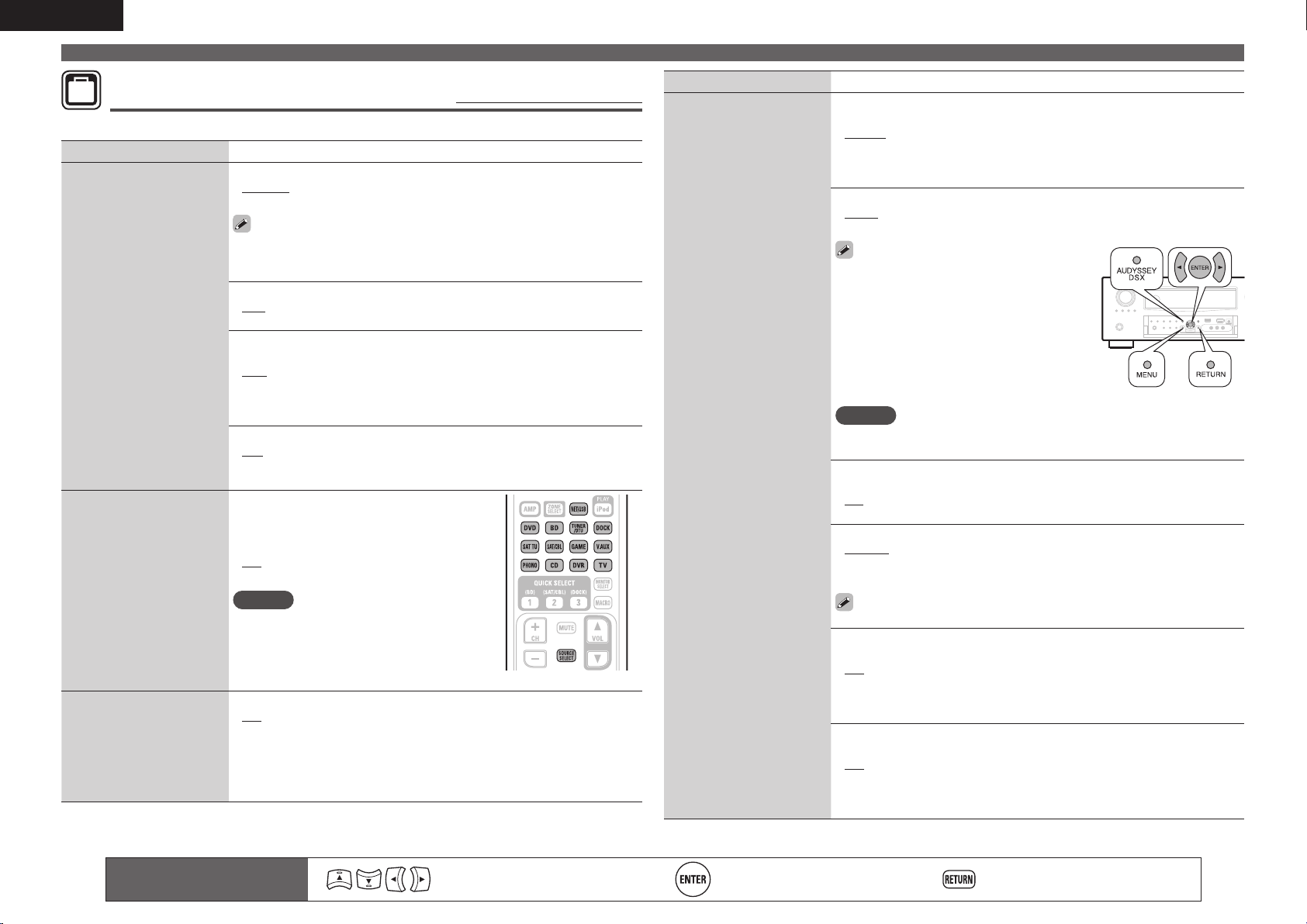
104
ENGLISH
Remote control operation
buttons
Move the cursor
(Up/Down/Left/Right)
Confi rm the setting Return to previous menu
MANUAL SETUP
OPTION
Option Setup
Default settings are underlined.
Make various other settings.
Setting items Setting details
Volume Control
Set the MAIN ZONE (room
where the unit is located)
volume setting.
Volume Display : Set how volume is displayed.
• Relative : Display ---dB (Min), in the range –80.5 dB to 18 dB.
• Absolute : Display in the range 0 (Min) to 99.
• The “Volume Display” setting is applied also to the “Volume Limit” and
“Power On Level” display method.
• The “Volume Display” setting applies to all zones.
Volume Limit : Make a setting for maximum volume.
• OFF : Do not set a maximum volume.
• –20dB (61) / –10dB (71) / 0dB (81)
Power On Level : Defi ne the volume setting that is active when the
power is turned on.
• Last : Use the memorized setting from the last session.
• – – –dB (0) : Always use the muting on condition when power is turned
on.
• –80dB – 18dB (1 – 99) : The volume is adjusted to the set level.
Mute Level : Set the amount of attenuation when muting is on.
• Full : The sound is muted entirely.
• –40dB : The sound is attenuated by 40 dB down.
• –20dB : The sound is attenuated by 20 dB down.
Source Delete
Remove from the display
input sources that are not
used.
PHONO / CD / BD / DVD / TV / SAT/CBL /
DVR / GAME / V.AUX / DOCK / NET/USB /
SIRIUS / HD Radio : Select input source that
is not used.
• ON : Use this source.
• Delete : Do not use this source.
NOTE
• Input sources being used in the various
zones cannot be deleted.
• Input sources set to “Delete” cannot be
selected using SOURCE SELECT.
GUI
Make the settings related to
displays on the TV screen.
Screensaver : Make screensaver settings.
• ON : The screensaver is activated during menu display, NET/USB, iPod,
SIRIUS or HD Radio screen display if no operation is performed for an
approximately 3-minute continuous period. When you press uio p,
the screensaver is cancelled and the screen before that screen saver
started is displayed.
• OFF : Screensaver is not activated.
Setting items Setting details
GUI
(Continued)
Wall Paper : Set wallpaper to display in the background when playback
is stopped, etc.
• Picture : Set the background to a picture (DENON logo).
• Black : Set the background to black.
• Gray : Set the background to gray.
• Blue : Set the background to blue.
Format : Set the video signal format to be output for the TV you are using.
• NTSC : Select NTSC output.
• PAL : Select PAL output.
“Format” can also be set by the following
procedure. However, the menu screen is not
displayed.
1. Press and hold the main unit’s AUDYSSEY
DSX
and RETURN for at least 3 seconds.
“Video Format” appears on the display.
2. Press o p and set the video signal format.
3. Press the main unit’s ENTER, MENU or
RETURN to complete the setting.
NOTE
When a format other than the video format of the connected TV is set, the
picture will not be displayed properly.
Text : Display the details of operation when switching surround mode,
input mode, etc.
• ON : Turn display on.
• OFF : Turn display off.
Master Volume : Display the master volume during adjustment.
• Bottom : Display at the bottom.
• Top : Display at the top.
• OFF : Turn display off.
When the master volume display is hard to see when superimposed
on movie subtitles, set to “Top”.
NET/USB : Set the NET/USB screen display time when the input source
is “NET/USB”.
• 30s : Show display for 30 seconds after operation.
• 10s : Show display for 10 seconds after operation.
• OFF : Turn display off.
• Always : Show display continuously.
iPod : Set the iPod screen display time when the input source is “DOCK”
or “iPod (USB)”.
• 30s : Show display for 30 seconds after operation.
• 10s : Show display for 10 seconds after operation.
• OFF : Turn display off.
• Always : Show display continuously.
1.AVRA100E3_ENG_1st_0824.indd 104 2010/08/26 17:48:21
105
Basic versionSimple version Information
ENGLISH
Advanced version
Remote control operation
buttons
Move the cursor
(Up/Down/Left/Right)
Confirm the setting Return to previous menu
MANUAL SETUP
Setting items Setting details
GUI
(Continued)
TUNER : Set the tuner screen display time when the input source is
“SIRIUS” or “HD Radio”.
• 30s : Show display for 30 seconds after operation.
• 10s : Show display for 10 seconds after operation.
• OFF : Turn display off.
• Always : Show display continuously.
Remote Preset Codes
Search a preset code to
register in the remote
control unit.
See “Registering preset codes” (vpage108).
Quick Select Name
Change the “Quick Select”
display title to one you
prefer.
• Up to 16 characters can be input.
• For character input, see page 78.
Zone Rename
Change the display title of
each zone to one you prefer.
• Up to 10 characters can be input.
• For character input, see page 78.
Trigger Out 1 /
Trigger Out 2
Select the condition for
activating Trigger Out 1/2 for
the input source, surround
mode, etc.
See “TRIGGER OUT jacks”
(vpage27) for more
information on trigger out.
Trigger Out 1/2
n When setting for zone (MAIN ZONE / ZONE2 / ZONE3)
Trigger out is activated through linkage to the power of the zone set
to “ON”.
n When setting for input source
Activate trigger out when the input source set to “ON” is selected.
Active for the zone set to “ON” with “When setting for zone”.
n When setting for surround mode
Activate trigger out when the surround mode set to “ON” is selected.
Active when the “MAIN ZONE” set to “ON” with “When setting
for zone” is selected, and when the input source set to “ON” with
“When setting for input source” is selected.
n When setting for HDMI monitor
Activate trigger out when the HDMI monitor set to “ON” is selected.
Activate trigger out when the HDMI monitor set to “ON” is
selected. Active when the “MAIN ZONE” set to “ON” with
“When setting for zone” is selected, and when the input source
set to “ON” with “When setting for input source” is selected.
n When setting for “Vertical Stretch”
Activate trigger out through linkage when “Vertical Stretch” (vpage98)
is set to “ON”.
• ON : Activate trigger on this mode.
• – – – : Do not activate trigger on this mode.
Setting items Setting details
Remote ID
Set when you operate
another DENON AV
amplifier with the remote
control unit of this unit.
Match the remote control
unit you are using with the
remote ID of this unit.
1 / 2 / 3 / 4
NOTE
When changing the remote ID, also change the remote ID of main remote
control unit (RC-1145) at the same time. Also change the sub remote
control unit (RC-1148) at the same time.
Dimmer
Adjust the display
brightness of this unit.
Bright : Normal display brightness.
Dim : Reduced display brightness.
Dark : Very low display brightness.
OFF : Turns the display off.
Setup Lock
Protect settings from
inadvertent change.
ON : Turn protection on.
OFF : Turn protection off.
When canceling the setting, set “Setup Lock” to “OFF”.
NOTE
When “Setup Lock” is set to “ON”, the settings listed below can no
longer be changed. Also, “SETUP LOCKED!” is displayed if you attempt
to operate related settings.
• Menu operations • Channel Level
• RESTORER • MultEQ
®
XT 32
• Dolby Volume • Dynamic EQ
®
• Dynamic Volume
®
Maintenance Mode
Use when receiving
maintenance from a DENON
service engineer or custom
installer.
NOTE
Only use this function if so instructed by a DENON serviceperson or
installer.
1.AVRA100E3_ENG_1st_0824.indd 105 2010/08/26 17:48:21
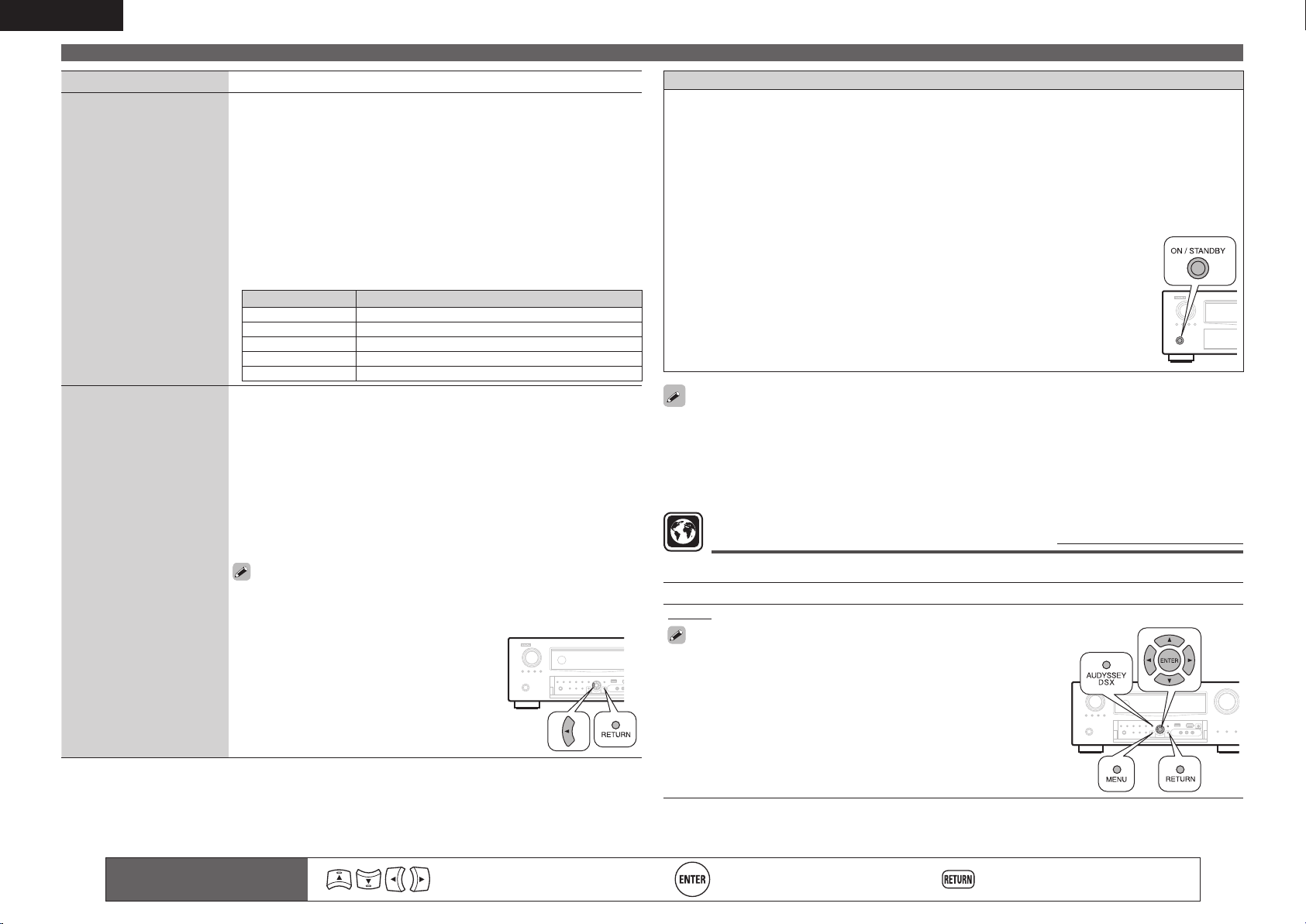
106
ENGLISH
Remote control operation
buttons
Move the cursor
(Up/Down/Left/Right)
Confi rm the setting Return to previous menu
MANUAL SETUP
Setting items Setting details
Firmware Update
Update the fi rmware of the
receiver.
Check for Update : Check for fi rmware updates. You can also check
approximately how long it will take to complete an update.
Start : Execute the update process.
When updating starts, the power indicator becomes red and the menu
screen is shut down. The amount of update time which has elapsed is
displayed.
When updating is complete, the power indicator becomes green and
normal status is resumed.
• If updating fails, the set automatically retries, but if updating is still not
possible, one of the messages shown below is displayed. If the display
reads as shown below, check the settings and network environment,
then update again.
Display Description
Updating fail Updating failed.
Login failed Failure to log into server.
Server is busy Server is busy. Wait a while then try again.
Connection fail Failure in connecting to server.
Download fail Downloading of the fi rmware has failed.
Add New Feature
Display new features that
can be downloaded to this
unit and perform an update.
Upgrade : Execute the upgrade process.
When updating starts, the power indicator becomes red and the menu
screen is shut down. The amount of update time which has elapsed is
displayed.
When upgrading is complete, the power indicator becomes green and
normal status is resumed.
• If the upgrade is not successful, an error message identical to those in
“Firmware Update” will appear on the display. Check the settings and
network environment, then update again.
Upgrade Status : Display a list of the additional functions provided by the
upgrade.
See the DENON website for details about updates.
When the procedure is complete, “Registered” is displayed in this
menu and updates can be carried out. If the procedure has not been
carried out, “Not Registered” is displayed.
The ID number shown on this screen
is needed when carrying out the
procedure.
The ID number can also be displayed by
pressing and holding
o and RETURN for
at least 3 seconds.
Notes concerning use of “Firmware Update” and “Add New Feature”
• In order to use these functions, you must have the correct system requirements and settings for a
broadband Internet connection (vpage26).
• Do not turn off the power until updating or upgrating is completed.
• Even with a broadband connection to the Internet, approximately 1 hour is required for the updating/
upgrading procedure to be completed.
• Once updating/upgrade starts, normal operations on this unit cannot be performed until updating/
upgrading is completed.
• Furthermore, updating/upgrading the fi rmware may reset the backup data for the parameters, etc. set
for this unit.
• The following backup data may be erased after an update or upgrade.
• Internet radio preset channel
• Internet radio Recently Played data
• Username registered for Flickr Contact
• Data in Internet radio, media server and USB memory device
• If the update or upgrade fails, press and hold the ON/STANDBY on the unit for more
than 5 seconds, or remove and re-insert the power cord. “Update retry” appears
on the display and update restarts from the point at which update failed. If the error
continues despite this, check the network environment.
• Information regarding the “Firmware Update” function and “Add New Feature” will be announced on
the DENON web site each time related plans are defi ned.
• When usable new fi rmware is released with “Firmware Update” or “Add New Feature”, a notifi cation
message is displayed on the menu screen. When you do not want to be notifi ed, set “Update Notifi cation”
(vpage102) and “Upgrade Notifi cation” (vpage102) to “OFF”.
Language
Default settings are underlined.
Set the language for display on the menu screen.
Setting details
English / Français
“Language” can also be set by the following procedure. However, the
menu screen is not displayed.
1. Press and hold the main unit’s AUDYSSEY DSX and RETURN for at
least 3 seconds.
“Video Format” appears on the display.
2. Press ui and set “GUI Language”.
3. Press o p and set the language.
4. Press the main unit’s ENTER, MENU or RETURN to complete the
setting.
1.AVRA100E3_ENG_1st_0824.indd 106 2010/08/26 17:48:22
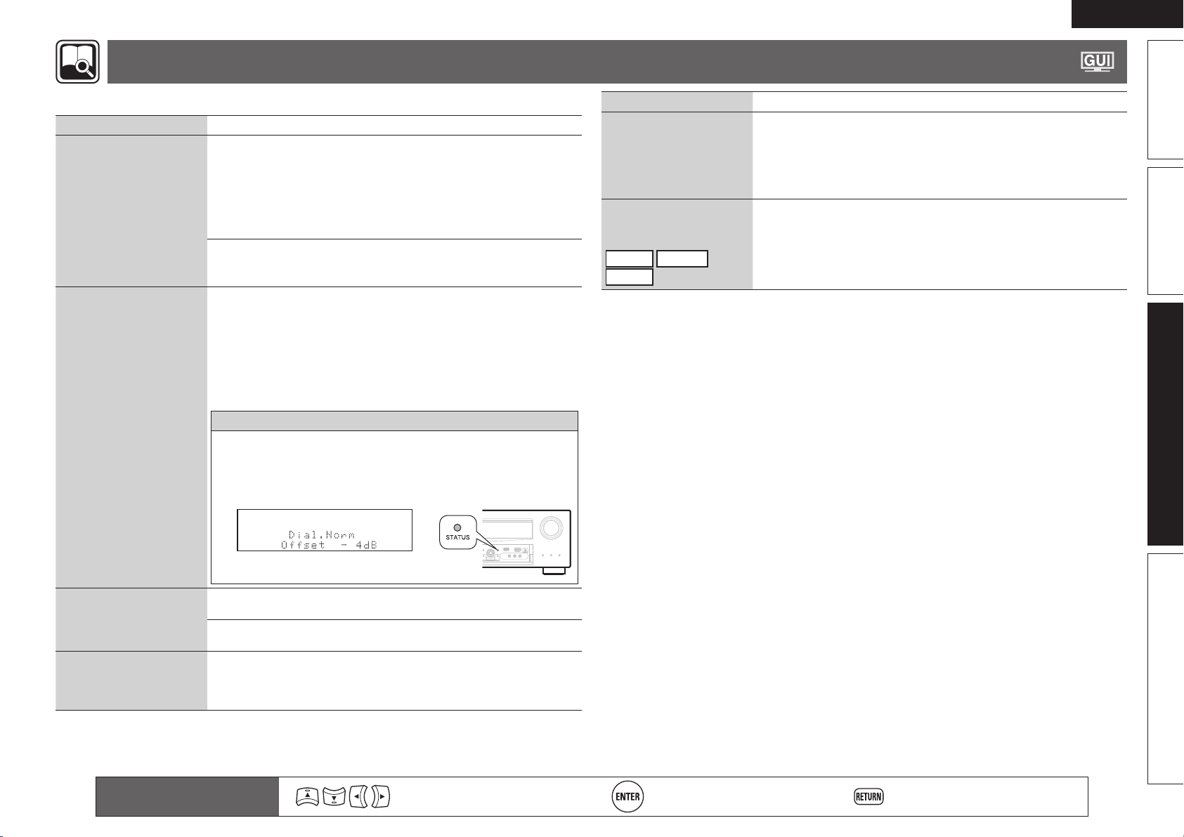
107
Basic versionSimple version Information
ENGLISH
Advanced version
Remote control operation
buttons
Move the cursor
(Up/Down/Left/Right)
Confi rm the setting Return to previous menu
INFORMATION
Show information about receiver settings, input signals, etc.
Items Setting details
Status
Show information about
current settings.
n MAIN ZONE
This item shows information about settings for MAIN ZONE.
The information displayed differs according to the input source.
Select Source / Name / Surround Mode / Input Mode /
Decode Mode / HDMI / Digital / Component / Rec Select /
Video Select / Video Mode / Content Type / Video Convert /
i/p Scaler / Resolution / Progressive Mode / Aspect etc.
n ZONE2/3
This item shows information about settings for ZONE2 or ZONE3.
ZONE2 / ZONE3 / Power / Select Source / Volume Level
Audio Input Signal
Show information about
audio input signals.
Surround Mode : The currently set surround mode.
Signal : The input signal type.
fs : The input signal’s sampling frequency.
Format : The number of channels in the input signal (front, surround, LFE).
Offset : The dialogue normalization correction value.
Flag : This is displayed when inputting signals including a surround back
channel. “MATRIX” is displayed with Dolby Digital EX and DTS-ES Matrix
signals, “DISCRETE” with DTS-ES Discrete signals.
Dialogue normalization function
This function is automatically activated when playing Dolby Digital
sources.
It automatically corrects the standard signal level for individual program
sources.
The correction value can be checked using the
STATUS.
The fi gure is the corrected value.
This cannot be changed.
HDMI Information
Show information about
HDMI input/output signals
and monitor.
Signal Info.
• Resolution / Color Space / Pixel Depth
Monitor 1 / Monitor 2
• Interface / Supported resol.
Auto Surround Mode
Show information about
auto surround mode
settings.
Analog/PCM 2ch / Digital 2ch / Digital 5.1ch / Multi ch
Items Setting details
Quick Select
Show information about
“Quick select function”
(vpage67) settings.
Quick Select 1 / Quick Select 2 / Quick Select 3 / ZONE2 Quick Select 1 /
ZONE2 Quick Select 2 / ZONE2 Quick Select 3 / ZONE3 Quick Select 1 /
ZONE3 Quick Select 2 / ZONE3 Quick Select 3
• Select Source / Video Select / Volume Level / MultEQ
®
XT 32 /
Dynamic EQ
®
/ Dynamic Volume
®
/ Analog/PCM 2ch / Digital 2ch /
Digital 5.1ch / Multi ch
Preset Channel
Show information about
preset channels.
SIRIUS
HD Radio
NET/USB
A / B / C / D / E / F / G
A1 – A8 / B1 – B8 / C1 – C8 / D1 – D8 / E1 – E8 / F1 – F8 / G1 – G8
1.AVRA100E3_ENG_1st_0824.indd 107 2010/08/26 17:48:22
108
ENGLISH
Operating the connected devices by remote control unit
Operating the main remote control unit
Registering the supplied preset codes in the remote control unit
enables you to operate devices made by other manufacturers.
Operating AV equipment
1
Press ZONE SELECT to select a
zone for operation.
The zone mode indicator corresponding
to the operating zone lights.
• The mode switches each time ZONE
SELECT
is pressed.
M
Select for the operations in MAIN
ZONE.
Z2
Select for the operations in ZONE2.
Z3
Select for the operations in ZONE3.
Z4
Not used.
2
Press the input source select button (vpage 28).
• The input source for the zone selected in step 1 is switched.
• The operation mode of the remote control unit is switched as
shown in the table.
Input
source
select
button
Input
source of
this unit
Operation mode
Display
Devices controllable with the
remote control unit
– This unit (AMP-operation)
z
2
z
1
BD
Device registered on the BD
button
z
1
DVD
Device registered on the DVD
button
z
1
TV
Device registered on the TV
button
z
1
SAT/CBL
Device registered on the SAT/
CBL
button
z
1
DVR
Device registered on the DVR
button
z
1
GAME
Device registered on the GAME
button
z
1
V.AUX
Device registered on the V.AUX
button
z
1
CD
Device registered on the CD
button
NET/USB or
DOCK
iPod connected to the USB port
or control dock for iPod.
DOCK Control dock for iPod
NET/USB
• Network function
• iPod or USB memory device
connected to the USB port
SIRIUS SIRIUS Satellite Radio
PHONO This unit (AMP-operation)
z
2
HD Radio HD Radio receiver
z1 If a preset code is registered for this button, the remote control
unit of this unit can control another devices.
z2 This operation mode enables you to operate iPod, USB, Control
dock for iPod, Network function, SIRIUS, and HD Radio receiver.
When SOURCE SELECT is pressed, the AMP-operation mode starts
automatically.
NOTE
If the mode of the remote control unit is set to other than AMP-
operation mode, press AMP to switch the remote control unit to the
AMP-operation mode to perform the following operations:
• For menu operation by pressing MENU
• For setting the channel level of the unit by pressing CH LEVEL
• For turning power in each zone on or off by pressing ZONE/DEVICE
ON
or ZONE/DEVICE OFF.
3
Operate this unit or the device whose input source is
switched.
• For details, refer to the operating instructions for each device.
For operations of iPod, SIRIUS, HD Radio receiver and USB
memory device, see the following pages.
• iPod (vpage31, 32)
• SIRIUS (vpage35)
• HD Radio receiver (vpage37)
• Network function (vpage40 – 47)
• USB memory device (vpage48)
Registering preset codes
When preset codes are registered in the included remote control unit,
it can then be used to operate any devices you have, such as DVD
players or TVs made by different manufacturers.
In this menu, you can search and display the preset codes that can be
preset in the included remote control unit.
n Buttons used for operating the devices
q ZONE/DEVICE ON, ZONE/DEVICE OFF
For switching power of each device on or off.
w uio p, ENTER, RETURN
For menu operation of each device.
e MENU, SETUP, TOP MENU
For displaying the menu of each device.
r 1, 2, 3, 6, 7, 8, 9
t Number button (0 – 9, +10)
y CH +, CH –
u TV POWER, TV INPUT
For operating a TV
This button is enabled in any mode.
For details on operation with the remote control unit, see pages 31,
32, 35, 37, 40 – 43, 45, 47, 49, 111.
1.AVRA100E3_ENG_1st_0824.indd 108 2010/08/26 17:48:23
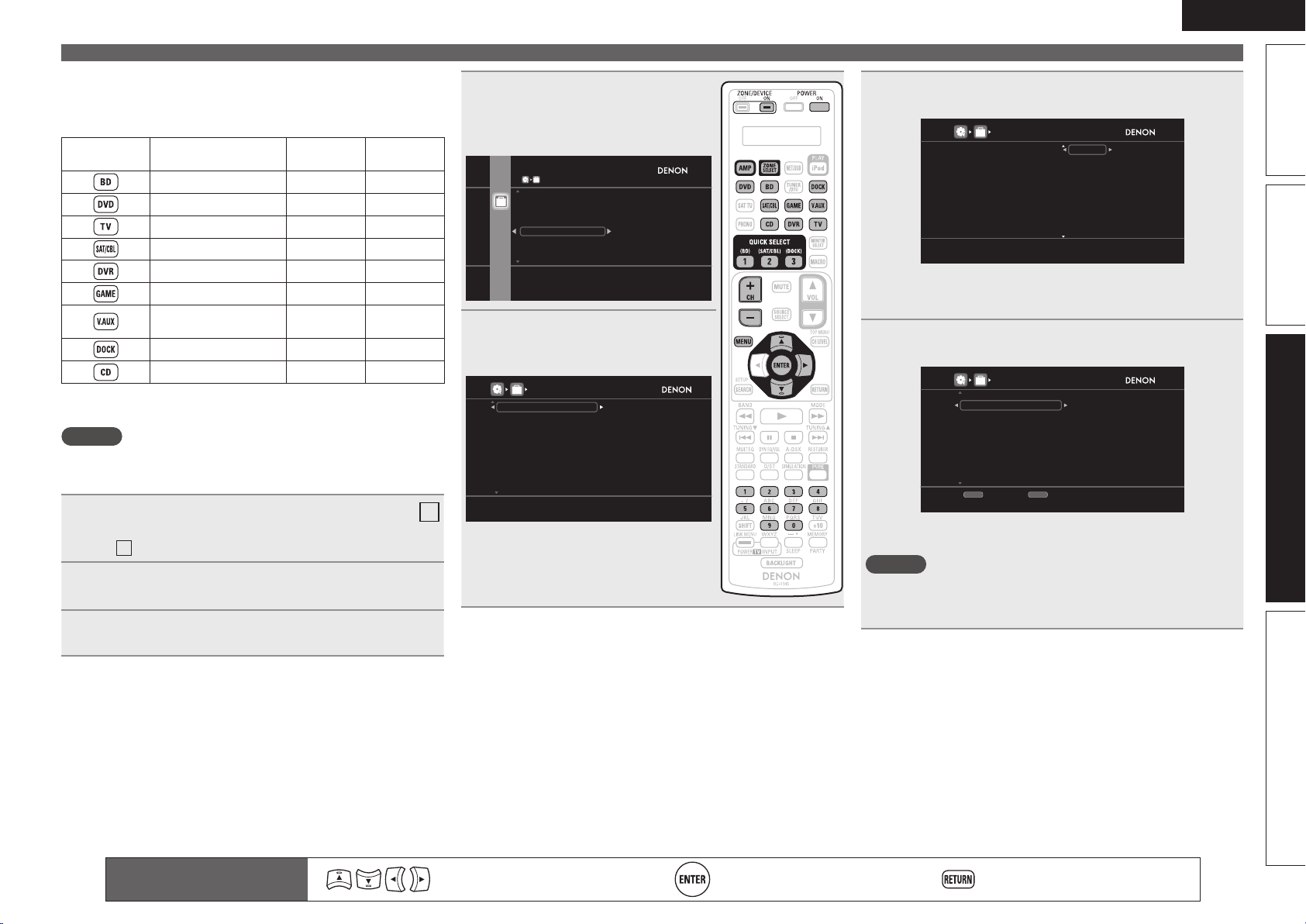
109
Basic versionSimple version Information
ENGLISH
Advanced version
Operating the main remote control unit
n Default settings for preset codes
The devices shown below are registered for each input source
button as default. Settings can be changed according to the
devices to be used.
Input source
select button
Category Brand Preset code
Blu-ray Disc player DENON 32258
DVD player DENON 32134
Television SONY 10810
Satellite set top box DirecTV 01377
DVD recorder Tivo 20739
Cable set top box Motorola 01376
Digital camcorder
(DVD recorder)
Panasonic 21378
z
Control dock for iPod DENON 62516
CD player DENON 42867
z If a control dock for iPod is not to be used, the preset code for
another device can be set to
DOCK.
NOTE
The preset code cannot be registered to TUNER/DTU, NET/USB, iPod,
PHONO or SAT TU.
1
Press ZONE SELECT to switch the zone mode to
M
(MAIN ZONE).
The
M
indicator lights.
2
Press AMP to set the remote control unit to AMP-
operation mode.
3
Press MENU.
The menu is displayed on the TV screen.
4
Use ui to select “MANUAL
SETUP” – “Option Setup” –
“Remote Preset Codes” and then
press ENTER or p.
OPTION SETUP
Search preset codes to register in the remote
controller
Volume Control
Source Delete
GUI
Remote Preset Codes
Quick Select Name
Zone Rename
OPTION
OPTION
5
Pressing ui, select the device
category for preset registration.
Then press ENTER or p.
REMOTE PRESET CODES
Select the device category
Blu-ray
CD
CD Recorder
CABLE
CABLE/PVR
DVD
DVD Recorder
HD-DVD
IPTV STB
PVR
D
I
J
L
M
N
O
P
S
T
OPTION
• For “TV”, “TV/DVD” or “TV/VCR”
categories, only the preset code for TV
can be registered.
6
Pressing ui, select the rst letter of the device
brand name. Then press ENTER or p.
REMOTE PRESET CODES
Select first letter of device brand
Blu-ray
CD
CD Recorder
CABLE
CABLE/PVR
DVD
DVD Recorder
HD-DVD
IPTV STB
PVR
1
A
B
C
D
E
F
G
H
I
OPTION
• The fi rst character is displayed as 1, A to Z. (Initials for the brand are
displayed for each category.)
For brand names that start with numbers and symbols, select “1”.
7
Pressing ui, select the device brand name. Then
press ENTER or p.
REMOTE PRESET CODES
[1/4]
Daenyx
Daewoo
Dalton
Dansai
Dantax
Datsun
Daytek
Dayton
DCE
-DVD-
Select the device brand
CH-
Previous
CH+
Next
OPTION
• When there are several pages of brand names, the pages can be
switched by pressing the remote control unit’s CH + or CH –.
NOTE
If the desired brand name is not listed, the supplied remote control
unit cannot control the device. Use the remote control unit supplied
with the device to be used.
Remote control operation
buttons
Move the cursor
(Up/Down/Left/Right)
Confi rm the setting Return to previous menu
1.AVRA100E3_ENG_1st_0824.indd 109 2010/08/26 17:48:24
110
ENGLISH
8
The procedures for registering remote control codes
and remote control preset registration are displayed.
Press QUICK1 if device works, QUICK2 if not
QUICK3
Return
REMOTE PRESET CODES
Category
Brand
Code [ 1/ 4]
1. Press and hold 3sec.both[POWER ON][DEVICE ON]
button.”PRSET” is displayed on remote.
2. Press [ENTER] button. “MODE?”is displayed on remote.
3. Press [Input Souce] button.
4. Input Code with [0-9] button.
5. Press any key to check device. (e.g. [DEVICE ON])
: DVD
: Denon
: 30490
QUICK2
NG
QUICK1
OK
OPTION
NOTE
If a wrong brand name is selected, press QUICK SELECT 3. The
following screen is displayed:
Press QUICK1 if device works, QUICK2 if not
QUICK1
Return
REMOTE PRESET CODES
QUICK2
NG
QUICK1
OK
: TV
: Sanyo
:
11037
Category
Brand
Code [ 1/ 3]
1. Press [INPUT SOURCE] button.
button
2. Press and hold 3sec. both [POWER ON]
3. Press
4. Input with [0-9] button.
5. Press any key to check device.
O K
Press[AMP] button.
And press [ENTER] button to return
Bland select menu.
OPTION
Press AMP then ENTER to return to step 7.
9
Hold POWER ON and ZONE/DEVICE ON pressed
simultaneously for more than 3 seconds.
“SETUP” fl ashes twice on the remote control unit.
10
When “PRSET” appears on the remote control unit,
press ENTER.
11
When “MODE?” appears on the remote control
unit, press the input source select button of the AV
equipment (DVD, BD, SAT/CBL, DVR, DOCK, V.AUX,
GAME, CD or TV) that you want to program for the
preset setting.
• For TV, only the preset code for the categories “TV”, “TV/DVD” or
“TV/VCR” can be registered.
Operating the main remote control unit
12
When “– – – – –” appears on the remote control unit,
press the number buttons 0 – 9 to enter a 5-digit code.
Press the buttons with an interval less than 30 seconds.
Press QUICK1 if device works, QUICK2 if not
QUICK3
Return
REMOTE PRESET CODES
Category
Brand
Code [ 1/ 4]
1. Press and hold 3sec.both[POWER ON][DEVICE ON]
button.”PRSET” is displayed on remote.
2. Press [ENTER] button. “MODE?”is displayed on remote.
3. Press [Input Souce] button.
4. Input Code with [0-9] button.
5. Press any key to check device. (e.g. [DEVICE ON])
: DVD
: Denon
: 30490
QUICK2
NG
QUICK1
OK
OPTION
• When the code is registered.
“SET” fl ashes four times on the remote control unit.
• When the code is not registered correctly
“NG” fl ashes four times on the remote control unit.
Perform from step 9 again.
• When an input number is not correct
Press POWER ON once then perform the operations from step
9 again.
13
Operate the device being used to check the operation.
• If the device is operating, press QUICK SELECT 1.
Go to step 14.
• If the device is not operating, press QUICK SELECT 2.
Go to step 15.
14
The screen shown below is displayed, and registration
of the preset code is completed.
Press QUICK1 if device works, QUICK2 if not
QUICK1
Return
REMOTE PRESET CODES
QUICK2
NG
QUICK1
OK
: TV
: Sanyo
:
11037
Category
Brand
Code [ 1/ 3]
1. Press [INPUT SOURCE] button.
2. Press and hold 3sec. both [POWER ON]
button.
3. Input Code with [0-9] button.
4. Press any key to check device.
(e.g. [DEVICE ON])
O K
Remote Preset Codes setup is finished.
Press[AMP] button.
And press [ENTER] button to return
MENU.
OPTION
• The menu screen is retrieved. Press AMP then ENTER.
15
Either of the screens below is displayed.
q
Press QUICK1 if device works, QUICK2 if not
QUICK1
Return
REMOTE PRESET CODES
QUICK2
NG
QUICK1
OK
: TV
: Sanyo
:
11037
Category
Brand
Code [ 1/ 3]
1. Press [INPUT SOURCE] button.
2. Press and hold 3sec. both [POWER ON]
button.
3. Input Code with [0-9] button.
4. Press any key to check device.
(e.g. [DEVICE ON])
Selected code is not matched.
Plesse try other codes.
OPTION
• The screen is displayed for 3 seconds, then the next preset
registration screen is displayed automatically.
w
Press QUICK1 if device works, QUICK2 if not
QUICK1
Return
REMOTE PRESET CODES
QUICK2
NG
QUICK1
OK
: TV
: Sanyo
:
11037
Category
Brand
Code [ 1/ 3]
1. Press [INPUT SOURCE] button.
2. Press and hold 3sec. both [POWER ON]
button.
3. Input Code with [0-9] button.
4. Press any key to check device.
(e.g. [DEVICE ON])
O K
Sorry, your remote is not supported.
This function can not be used for
your device.
Press[AMP] button.
And press[ENTER] button to return
MENU.
OPTION
GIf screen q is displayedH
The device may be operating with the preset code displayed next.
The preset registration screen is displayed. Repeat steps 9 to 13.
GIf screen w is displayedH
The device cannot be controlled with the remote control unit supplied
with this unit. Use the remote control unit supplied with the device
to be used. The menu screen is retrieved. Press AMP then ENTER.
Some manufacturers use more than one type of remote control code.
Preset codes to change the number and verify correct operation.
NOTE
Depending on the model and year of manufacture of your equipment,
some buttons may not operate.
Remote control operation
buttons
Move the cursor
(Up/Down/Left/Right)
Confi rm the setting Return to previous menu
1.AVRA100E3_ENG_1st_0824.indd 110 2010/08/26 17:48:24
111
Basic versionSimple version Information
ENGLISH
Advanced version
Operating components
The supplied remote control unit can control a component other than
this unit.
1
Press the input source select
button to which the preset
code for the device you want
to operate has been registered
(vpage 108).
2
Operate the component.
• For details, refer to the component’s
operating instructions.
n Blu-ray Disc player / HD-DVD player /
DVD player / DVD recorder operation
Operation buttons Function
ZONE/DEVICE ON
Power onz
ZONE/DEVICE OFF
Power standbyz
CH +, – Switch channels (up/down)
MENU (Popup) Menu
TOP MENU Top menu
uio p
Cursor operation
ENTER Enter
SETUP Setup
RETURN Return
6 7
Manual search
(fast-reverse/fast-forward)
1
Playback
8 9
Auto search (cue)
3
Pause
2
Stop
0 – 9, +10
Select title, chapter or channel
selection
TV POWER TV power on/standby (Default : SONY)
TV INPUT Switch TV input (Default : SONY)
zThis may power some devices on/standby.
Operating the main remote control unit
n CD player / CD recorder operation
Operation buttons Function
ZONE/DEVICE ON
Power onz
ZONE/DEVICE OFF
Power standbyz
uio p
Cursor operation
ENTER Enter
6 7
Manual search
(fast-reverse/fast-forward)
1
Playback
8 9
Auto search (cue)
3
Pause
2
Stop
0 – 9, +10 Track selection
TV POWER TV power on/standby (Default : SONY)
TV INPUT Switch TV input (Default : SONY)
zThis may power some devices on/standby.
n Digital video recorder (PVR) /
video cassette recorder (VCR) operation
Operation buttons Function
ZONE/DEVICE ON
Power onz
ZONE/DEVICE OFF
Power standbyz
CH +, – Switch channels (up/down)
MENU Menu
uio p
Cursor operation
ENTER Enter
SETUP Setup
RETURN Return
6 7
Manual search
(fast-reverse/fast-forward)
1
Playback
8 9
Auto search (cue)
3
Pause
2
Stop
0 – 9, +10
Select title, chapter or channel
selection
TV POWER TV power on/standby (Default : SONY)
TV INPUT Switch TV input (Default : SONY)
zThis may power some devices on/standby.
n TV operation
Operation buttons Function
ZONE/DEVICE ON
Power onz
ZONE/DEVICE OFF
Power standbyz
CH +, – Switch channels (up/down)
MENU Menu
uio p
Cursor operation
SETUP Setup
ENTER Enter
RETURN Return
6 7
Manual search
(fast-reverse/fast-forward)
1
Playback
8 9
Auto search (cue)
3
Pause
2
Stop
0 – 9, +10 Channel selection
TV POWER TV power on/standby (Default : SONY)
TV INPUT Switch TV input (Default : SONY)
zThis may power some devices on/standby.
n Set top box for satellite (SAT) / cable (CBL) /
IP TV operation
Operation buttons Function
ZONE/DEVICE ON
Power onz
ZONE/DEVICE OFF
Power standbyz
CH +, – Switch channels (up/down)
MENU Menu
uio p
Cursor operation
ENTER Enter
SETUP Guide
RETURN Return
6 7
Manual search
(fast-reverse/fast-forward)
1
Playback
8 9
Auto search (cue)
3
Pause
2
Stop
0 – 9, +10 Channel selection
TV POWER TV power on/standby (Default : SONY)
TV INPUT Switch TV input (Default : SONY)
zThis may power some devices on/standby.
1.AVRA100E3_ENG_1st_0824.indd 111 2010/08/26 17:48:25
112
ENGLISH
Operating the main remote control unit
Operating learning function
If the AV device is not a DENON device, or if the device does not
operate even when the preset code is registered, use the learning
function. Remote codes for different devices can be remembered for
use by the DENON remote control included with this device.
n Remembering remote control codes from other
devices
1
Press and hold POWER ON and
ZONE/DEVICE ON for at least 3
seconds.
“SETUP” flashes twice on the remote
control unit.
2
Use ui to display “LEARN” on
the remote control unit and press
ENTER.
3
When “MODE?” appears on the
remote control unit, press the
input source select button of the
AV equipment that you want to
store.
• You cannot store the remote control code in
the AMP button.
4
When “KEY? ” appears on the remote control unit,
press the button that you want to store.
• You cannot store the remote control code in the POWER ON,
POWER OFF, ZONE SELECT, SOURCE SELECT, MACRO, QUICK
SELECT 1 – 3
, BACK LIGHT and input source select button.
5
When “SEND
↑
” appears on the remote control unit,
place the remote control unit of the AV equipment
face to face with main remote control unit (of this
unit). Next, press and hold down the desired button
(that you want to store) of the remote control unit of
the AV equipment.
• When the button is correctly stored, “OK” flashes four times on
the remote control unit.
• If the button is not correctly stored, “FAIL” flashes four times on
the remote control unit. If this happens, perform step 4 again.
6
To store another button, repeat steps 4 and 5.
7
When you have nished storing the remote control
codes, press POWER ON.
“SET” flashes four times on the remote control unit and the
normal operation mode is restored.
• There are some remote control units that cannot be programmed,
or even if they can be programmed, they may not operate correctly.
If this happens, use the remote control unit supplied with the AV
equipment to operate it.
• The operations of the programmed buttons override the preset
memory. If you do not require the programmed buttons, erase
the stored remote control codes to return to the initial settings
(vpage112 “Operating learning function”).
• The number of buttons that can be stored varies depending on the
remote control unit used. If you have stored the maximum number
of buttons allowed for the remote control unit, “FAIL” appears on
its display.
n Erasing stored remote control codes
Erasing the code by each button
1
Press and hold POWER ON and
ZONE/DEVICE ON for at least 3
seconds.
“SETUP” flashes twice on the remote
control unit.
2
Use ui to display “RESET” on
the remote control unit and press
ENTER.
3
When “LEARN” appears on the
remote control unit, press ENTER.
4
When “MODE?” appears on the
remote control unit, press the
input source select button of the
AV equipment that you want to
erase.
5
Use ui to display “ONE?” on the remote control
unit and press ENTER.
6
When “KEY?” appears on the remote control unit,
press the button that you want to erase.
“RESET” flashes four times on the remote control unit and the
normal operation mode is restored.
1.AVRA100E3_ENG_1st_0824.indd 112 2010/08/26 17:48:26
113
Basic versionSimple version Information
ENGLISH
Advanced version
Erasing the code by each equipment input source
1
Press and hold POWER ON and
ZONE/DEVICE ON for at least 3
seconds.
“SETUP” flashes twice on the remote
control unit.
2
Use ui to display “RESET”
on the remote control unit and
press ENTER.
3
When “LEARN” appears on
the remote control unit, press
ENTER.
4
When “MODE?” appears on the
remote control unit, press the
input source select button of the
AV equipment that you want to
erase.
5
When “ALL?” appears, press ENTER.
“RESET” flashes four times on the remote control unit and the
normal operation mode is restored.
Operating the main remote control unit
Operating macro function
• When the macro function is used, operations that usually require a
complicated series of multiple button operations can be performed
easily just by pressing the MACRO button.
• This device can remember up to 3 macro functions.
• Each macro can record a maximum of 18 steps.
[Example] All system power on
q Turn the TV’s power on
↓
w Turn this unit’s power on
↓
e Switch this unit’s input source to DVD
↓
r Turn the DVD’s power on
n Recording macro operations
1
Press and hold POWER ON and ZONE/DEVICE ON
for at least 3 seconds.
“SETUP” flashes twice on the remote control unit.
2
Use ui to display “MACRO”
on the remote control unit and
press ENTER.
3
When “MCNo? ” appears on the
remote control unit, press the
QUICK SELECT button that you
want to store.
Button Macro number
QUICK SELECT 1 MACRO-1
QUICK SELECT 2 MACRO-2
QUICK SELECT 3 MACRO-3
4
Press the buttons to be stored one
by one.
• The step number for the storing procedure and mode are alternately
displayed on the remote control unit.
• You cannot store the macros for the ZONE SELECT, SOURCE
SELECT
and BACK LIGHT buttons.
5
Press MACRO to exit the macro function.
“SET” flashes four times on the remote control unit and the
normal operation mode is restored.
n Adjusting the interval time of macro operations
transmitting
The macro operation transmission interval can be adjusted.
• The factory setting is “0.5 sec”.
1
Press and hold POWER ON and
ZONE/DEVICE ON for at least 3
seconds.
“SETUP” flashes twice on the remote
control unit.
2
Use ui to display “MACRO”
on the remote control unit and
press ENTER.
3
When “MCNo?” appears on the
remote control unit, press the
QUICK SELECT button that you
want to set.
Button Macro number
QUICK SELECT 1 MACRO-1
QUICK SELECT 2 MACRO-2
QUICK SELECT 3 MACRO-3
4
Press MACRO many times to set the macro operation
transmission interval and press ENTER.
“SET” flashes four times on the remote control unit and the
normal operation mode is restored.
Remote control unit display
Time values that you can
set
0.25 0.25 sec
0.50 0.5 sec
0.75 0.75 sec
1.00 1 sec
1.25 1.25 sec
1.AVRA100E3_ENG_1st_0824.indd 113 2010/08/26 17:48:26
114
ENGLISH
Operating the main remote control unit
n Using the macro function
1
Press MACRO.
2
Press the QUICK SELECT button
you used to store the macro
function.
Button Macro number
QUICK SELECT 1 MACRO-1
QUICK SELECT 2 MACRO-2
QUICK SELECT 3 MACRO-3
n Resetting the macro function
1
Press and hold POWER ON and
ZONE/DEVICE ON for at least 3
seconds.
“SETUP” flashes twice on the remote
control unit.
2
Use ui to display “RESET” on
the remote control unit and press
ENTER.
3
Use ui to display “MACRO”
on the remote control unit and
press ENTER.
4
When “MCNo? ” appears on the
remote control unit, press the
QUICK SELECT button that you
want to reset.
“RESET” flashes four times on the
remote control unit and the normal
operation mode is restored.
Button Macro number
QUICK SELECT 1 MACRO-1
QUICK SELECT 2 MACRO-2
QUICK SELECT 3 MACRO-3
Specifying the zone used with the main
remote control unit
When the ZONE SELECT button is pressed, only the set zone can be
operated with the remote control unit.
• The factory setting is “M234”.
1
Press and hold POWER ON and
ZONE/DEVICE ON for at least 3
seconds.
“SETUP” flashes twice on the remote
control unit.
2
Use ui to display “ZONEL” on
the remote control unit and press
ENTER.
3
Use ui to set the zone to be used
and press ENTER.
“SET” flashes four times on the remote
control unit and the normal operation
mode is restored.
Remote control unit
display
Zone to be used
M MAIN ZONE only
M2
MAIN ZONE /
ZONE2
M23
MAIN ZONE /
ZONE2 /
ZONE3
M234
MAIN ZONE /
ZONE2 /
ZONE3 /
ZONE4
Setting the Remote ID
When using multiple DENON AV receivers in the same room, make
this setting so that only the desired AV receiver operates.
• The factory setting is “ID-1”.
1
Press and hold POWER ON and
ZONE/DEVICE ON for at least 3
seconds.
“SETUP” flashes twice on the remote
control unit.
2
Use ui to display “RC-ID” on
the remote control unit and press
ENTER.
3
Use ui to set the remote ID and
press ENTER.
“SET” flashes four times on the remote
control unit and the normal operation
mode is restored.
Remote control unit
display
Remote ID
ID-1 1
ID-2 2
ID-3 3
ID-4 4
NOTE
When you change the remote ID, make sure that the remote
control unit and the remote ID of the main unit are exactly the same
(vpage105).
1.AVRA100E3_ENG_1st_0824.indd 114 2010/08/26 17:48:27
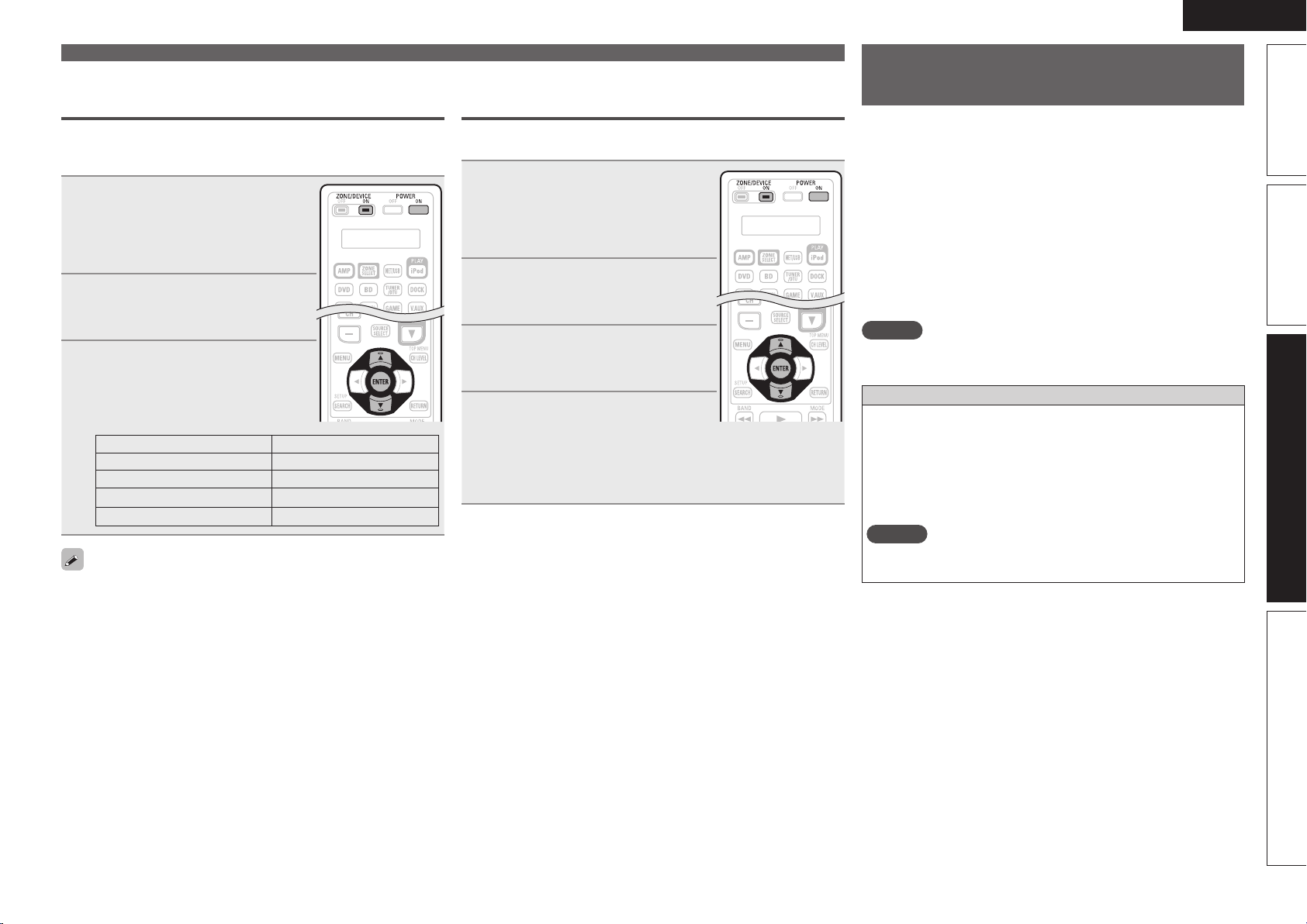
115
Basic versionSimple version Information
ENGLISH
Advanced version
Operating the sub remote control
unit
• The sub remote control unit is equipped with frequently used
buttons, so it can be used for simple remote control unit operations.
• The sub remote control unit can also be used for multi-zone, so you
can use it to control this unit from other rooms.
• The operations listed below can be performed with the sub remote
control unit.
• Switching the input source
• Adjusting the volume
• SIRIUS, HD Radio and iPod operations
• NET/USB direct play
• Menu operations
• Zone power on/off
• It is not possible to operate devices other than the amplifier.
NOTE
This unit cannot be used in the ZONE4 mode.
DIRECT PLAY button
• Playback is possible in the mode selected at menu “Direct Play”.
FAVORITES
Playback starts from the first track registered in the favorites.
ALL MUSIC
Playback starts from the first track registered in the “Music” folder.
• When USB is pressed, playback starts from the first track on the
USB memory device.
NOTE
When the media server is stopped or restarted, it may no longer be
possible to play tracks stored in the favorites.
Setting the display time length of the
remote control unit display
Use the following procedure to set the length of time for which to
display data such as zone and mode on the display panel of the remote
control unit.
1
Press and hold POWER ON and
ZONE/DEVICE ON for at least 3
seconds.
“SETUP” flashes twice on the remote
control unit.
2
Use ui to display “LCD” on
the remote control unit and press
ENTER.
3
Use ui to set the display time
length and press ENTER.
“SET” flashes four times on the remote
control unit and the normal operation
mode is restored.
Remote control unit display Display time
05SEC 5 sec
10SEC 10 sec
15SEC 15 sec
30SEC 30 sec
The backlight of the remote control unit lights for 10 sec.
Operating the main remote control unit
Restoring all settings of the remote control
unit to default
Use the following procedure to restore all default settings of the
remote control unit at the time of purchase.
1
Press and hold POWER ON and
ZONE/DEVICE ON for at least 3
seconds.
“SETUP” flashes twice on the remote
control unit.
2
Use ui to display “RESET” on
the remote control unit and press
ENTER.
3
Use ui to display “ALL” on
the remote control unit and press
ENTER.
4
Use ui to display “YES” on
the remote control unit and press
ENTER.
“RESET” flashes four times on the
remote control unit and the normal
operation mode is restored.
1.AVRA100E3_ENG_1st_0824.indd 115 2010/08/26 17:48:27

116
ENGLISH
3
Operate this unit or the device whose input source is
switched.
• For details, refer to the operating instructions for each device.
For operations of iPod, SIRIUS, HD Radio receiver and USB memory
device, see the following pages.
• iPod (vpage116)
• SIRIUS (vpage117)
• HD Radio receiver (vpage117)
• Network function (vpage117)
• USB memory device (vpage117)
n iPod operation
Operation buttons Function
Zone selection M Z2 Z3
ZONE SELECT Zone operation mode selection
ZONE OFF Power turned off
z2
ZONE ON Power turned on
z2
QUICK SELECT Quick select operation
INPUT SOURCE
SELECT
Input source selection
VOL +, – Adjustment of volume
z2
MUTE Muting
z2
MENU Selected zone menu
uio p
Cursor operation
ENTER Enter
SEARCH
Page forward screen /
Browse/Remote mode switching
(press and hold)
RETURN Return
8 9
Track search
2
Stop
1/3
Playback / Pause
REPEAT 1-track/All-track repeat play
RANDOM 1-track/album shuffle play
USB
z3
ALL MUSIC
z1
(Media server only)
z4
FAVORITES
z1
z5
z1 Whether “Music” or “Favorites” is selected depends on the
“Direct Play” setting (vpage85).
z2 Affects the currently selected zone.
z3 The input source switches to “NET/USB” and the files on the
USB memory device are played.
z4 The input source switches to “NET/USB” and the files in “Music”
on the media server are played.
z5 The input source switches to “NET/USB” and the files in
“Favorites” are played.
Operating the sub remote control unit
Operating AV equipment
Use this procedure to select the zone to be operated by the sub
remote control unit.
1
Press ZONE SELECT to select a
zone for operation.
The zone mode indicator corresponding
to the operating zone lights.
• The mode switches each time ZONE
SELECT
is pressed.
M
Select for the operations in MAIN ZONE.
Z2
Select for the operations in ZONE2.
Z3
Select for the operations in ZONE3.
Z4
Not used.
2
Press the input source select button.
• The input source for the zone selected in step 1 is switched.
• The operation mode of the remote control unit is switched as
shown in the table.
Input
source
select
button
Input source
of this unit
Devices controllable with the remote
control unit
(Operation mode)
BD
BD –
DVD
DVD –
TV
TV –
SAT/CBL
SAT/CBL –
DVR
DVR –
GAME
GAME –
V.AUX
V.AUX –
CD
CD –
DOCK DOCK Control dock for iPod
NET/
USB
NET/USB
• Network function
• iPod or USB memory device connected
to the USB port
SAT TU SIRIUS SIRIUS Satellite Radio
PHONO PHONO –
TUNER,
DTU
HD Radio HD Radio receiver
1.AVRA100E3_ENG_1st_0824.indd 116 2010/08/26 17:48:27
117
Basic versionSimple version Information
ENGLISH
Advanced version
Operating the sub remote control unit
n Tuner (HD Radio reception) operation
Operation buttons Function
Zone selection M Z2 Z3
ZONE SELECT Zone operation mode selection
ZONE OFF Power turned off
z2
ZONE ON Power turned on
z2
QUICK SELECT Quick select operation
INPUT SOURCE
SELECT
Input source selection
CH +, – Preset channel selection
SHIFT Preset channel block selection
VOL +, – Adjustment of volume
z2
MUTE Muting
z2
MENU Selected zone menu
MEMORY Preset memory registration
uio p
Multicast switching (ui) /
Cursor operation
TUNING df
Tuning up/down
USB
z3
ALL MUSIC
z1
(Media server only)
z4
FAVORITES
z1
z5
z1 Whether “Music” or “Favorites” is selected depends on the
“Direct Play” setting (vpage85).
z2 Affects the currently selected zone.
z3 The input source switches to “NET/USB” and the files on the
USB memory device are played.
z4 The input source switches to “NET/USB” and the files in “Music”
on the media server are played.
z5 The input source switches to “NET/USB” and the files in
“Favorites” are played.
n SAT TU (SIRIUS) operation
Operation buttons Function
Zone selection M Z2 Z3
ZONE SELECT Zone operation mode selection
ZONE OFF Power turned off
z2
ZONE ON Power turned on
z2
QUICK SELECT Quick select operation
INPUT SOURCE
SELECT
Input source selection
CH +, – Preset channel selection
SHIFT Preset channel block selection
VOL +, – Adjustment of volume
z2
MUTE Muting
z2
MENU Selected zone menu
MEMORY Preset memory registration
uio p
Category search / Cursor operation
ENTER
To Parental Lock password check
screen (press and hold)
TUNING df
Channel selection
USB
z3
ALL MUSIC
z1
(Media server only)
z4
FAVORITES
z1
z5
z1 Whether “Music” or “Favorites” is selected depends on the
“Direct Play” setting (vpage85).
z2 Affects the currently selected zone.
z3 The input source switches to “NET/USB” and the files on the
USB memory device are played.
z4 The input source switches to “NET/USB” and the files in “Music”
on the media server are played.
z5 The input source switches to “NET/USB” and the files in
“Favorites” are played.
n NET/USB operation
Operation buttons Function
Zone selection M Z2 Z3
ZONE SELECT Zone operation mode selection
ZONE OFF Power turned off
z2
ZONE ON Power turned on
z2
QUICK SELECT Quick select operation
INPUT SOURCE
SELECT
Input source selection
CH +, – Preset channel selection
SHIFT Preset channel block selection
VOL +, – Adjustment of volume
z2
MUTE Muting
z2
MENU Selected zone menu
MEMORY Favorites / Preset memory registration
uio p
Cursor operation
ENTER Enter
SEARCH
Page forward screen /
Character search
RETURN Return
8 9
Track search
2
Stop
1/3
Playback / Pause
REPEAT 1-track/All-track repeat play
RANDOM 1-track random play
USB
z3
ALL MUSIC
z1
(Media server only)
z4
FAVORITES
z1
z5
z1 Whether “Music” or “Favorites” is selected depends on the
“Direct Play” setting (vpage85).
z2 Affects the currently selected zone.
z3 The input source switches to “NET/USB” and the files on the
USB memory device are played.
z4 The input source switches to “NET/USB” and the files in “Music”
on the media server are played.
z5 The input source switches to “NET/USB” and the files in
“Favorites” are played.
1.AVRA100E3_ENG_1st_0824.indd 117 2010/08/26 17:48:27
118
ENGLISH
Switching the multi-zone input source to
the same input source as used in the MAIN
ZONE
This function is convenient for example when you want to listen to the
same song as the one playing in the MAIN ZONE while in a different
zone.
1
Press ZONE SELECT and set to
ZONE2 or ZONE3.
The currently selected multi-zone
indicator illuminates.
2
Press M.ZONE CALL on the sub
remote control unit.
The multi-zone input source switches to
the MAIN ZONE’s input source.
NOTE
• This function cannot be used for the MAIN ZONE.
• When M.ZONE CALL is pressed while the multi-zone power is off,
the multi-zone power turns on and the input source switches to the
MAIN ZONE’s input source.
Setting the zone for which the sub remote
control unit is used
(Zone select lock mode)
We recommend always using the sub remote control unit for the
same room. When this is done, the unit can be set so that the zone
does not switch when buttons are operated.
1
Use the tip of a pen to press
ADVANCED SETUP.
All the multi-zone indicators illuminate.
ADVANCED SETUP
2
Select the multi-zone to be set.
The selected multi-zone indicator
illuminates.
q To set to “MAIN ZONE”
Press
REPEAT.
w To set to “ZONE2”
Press
RANDOM.
e To set to “ZONE3”
Press
USB.
r To set to “ZONE4”
Press
ALL MUSIC/FAVORITES.
3
Use the tip of a pen to press ADVANCED SETUP.
The multi-zone indicator turns off.
n To cancel
1
Use the tip of a pen to press
ADVANCED SETUP.
The currently selected multi-zone
indicator illuminates.
ADVANCED SETUP
2
Press ZONE SELECT.
All the multi-zone indicator illuminates.
3
Use the tip of a pen to press ADVANCED SETUP.
The multi-zone indicator turns off.
Operating the sub remote control unit
Setting the remote ID
When using multiple DENON AV receivers in the same room, make
this setting so that no AV receiver other than the desired one operates.
1
While pressing MENU, press
ADVANCED SETUP with the tip
of a pen.
The multi-zone indicator corresponding
to the currently selected remote ID
flashes.
ADVANCED SETUP
2
Select the remote ID to be set.
q To set to 1
Press REPEAT.
The “M” indicator flashes.
w To set to 2
Press
RANDOM.
The “Z2” indicator flashes.
e To set to 3
Press
USB.
The “Z3” indicator flashes.
r To set to 4
Press
ALL MUSIC/FAVORITES.
The “Z4” indicator flashes.
3
While pressing MENU, press ADVANCED SETUP
with the tip of a pen.
The multi-zone indicator turns off.
NOTE
When changing a setting, be sure to set the same remote ID as this
unit’s (vpage105).
Resetting the settings
While pressing ZONE OFF, press
ADVANCED SETUP with the tip of a
pen.
All the multi-zone indicators flash four times,
then all the settings are restored to their
defaults.
ADVANCED SETUP
1.AVRA100E3_ENG_1st_0824.indd 118 2010/08/26 17:48:28

Information
119
Basic versionSimple version Advanced version Information
ENGLISH
119
Basic versionSimple version Advanced version Information
F Part names and functions vpage120
F Other information vpage125
F Troubleshooting vpage135
F Specifications vpage139
F Index vpage140
Information
Here, we list various information related to this unit.
Please refer to this information as needed.
1.AVRA100E3_ENG_1st_0824.indd 119 2010/08/26 17:48:28
120
ENGLISH
Front panel
For buttons not explained here, see the page indicated in parentheses ( ).
q w e
tioQ0
Q3 Q4Q2Q1
u y
r
q Power operation button
(ON/STANDBY) ······································ (7, 13)
Turns power to this unit on and off (standby).
w Power indicator ·········································· (13)
e Door
When you are using buttons and/or terminals
behind the door, press the bottom of the door
to open it. When not using buttons and/or
terminals behind the door, close it. Be careful
not to catch your fingers when closing the door.
r QUICK SELECT buttons ····························· (67)
t MASTER VOLUME control knob ··············· (28)
y AUDYSSEY DSX™ indicator ····················· (90)
u Master volume indicator
i Display ················································· (77, 121)
o Remote control sensor ···························· (124)
Q0 SOURCE SELECT knob ······························ (28)
Q1 SOURCE button ·········································· (28)
Q2 TUNING PRESET button ······················ (34, 36)
Q3 ZONE2/3 / REC SELECT button ·········· (67, 73)
Q4 iPod PLAY button ······································· (33)
Part names and functions
GWith the door openH
W3
Q5
Q6
Q7
Q8
Q9 W2
W1W0
W4
W8
E3
W6W7
E1E2
W9
E0
W5
Q5 Headphones jack
When the headphones are plugged into this
jack, audio will no longer be output from the
connected speakers or from the PRE OUT
connectors.
NOTE
To prevent hearing loss, do not raise the volume
level excessively when using headphones.
Q6 ZONE2 ON/OFF button ······························ (73)
Q7 ZONE3 ON/OFF button ······························ (73)
Q8 DYNAMIC EQ
®
/DYNAMIC VOLUME
®
button (DYNAMIC EQ/VOL) ················ (89, 90)
Q9 MENU button ·············································· (80)
W0 Cursor buttons (uio p) ·················· (76 – 80)
W1 ENTER button ····································· (77 – 80)
W2 RETURN button ·································· (77 – 80)
W3 V.AUX INPUT connectors ·························· (21)
W4 SETUP MIC jack ······································ (9, 63)
W5 HDMI IN connector ····································· (17)
W6 USB/iPod port ············································ (22)
W7 STATUS button ·································· (31, 107)
W8 AUDYSSEY DSX button ···························· (90)
W9 RESTORER button ······································ (92)
E0 DIRECT/STEREO button ···························· (52)
E1 PURE DIRECT button ································· (52)
E2 DSP SIMULATION button ·························· (52)
E3 STANDARD button ······························· (50, 51)
1.AVRA100E3_ENG_1st_0824.indd 120 2010/08/26 17:48:28

121
Basic versionSimple version Advanced version
ENGLISH
Information
Display
ioQ1Q9
Q0
W1W2 Q2Q3Q5Q6
Q4
Q8
Q7W0 u
wq e r t y
q Input signal indicators
w Input signal channel indicators
These light when digital signals are input.
When playing HD Audio sources, the
indicator lights when a signal from an extension
channel (a channel other than the front, center,
surround, surround back or LFE channel) is input.
If there are two or more extension channels, the
and indicators light.
e Information display
The input source name, surround mode, setting
values and other information are displayed here.
r Output signal channel indicators
Lights when audio signals are being output from
the speakers.
t Front speaker indicator
This lights according to the setting of the front A
and B speakers.
y Monitor output indicator
These light according to the HDMI monitor
output setting.
When set to “Auto (Dual)”, the indicators light
according to connection status.
u QUICK SELECT indicators
The indicator corresponding to the memory
for which Quick Select function is set, lights
(vpage67 “Quick select function”).
i Master volume indicator
o MUTE indicator
This lights when the mute mode is select
(vpage29).
Q0 Tuner reception mode indicators
These light according to the reception conditions
when the input source is set to “HD Radio”.
STEREO : In the FM mode, this light when
receiving stereo broadcasts.
TUNED : Lights when the broadcast is properly
tuned in.
AUTO : This light when in the auto tuning mode.
Q1 PARTY indicators
These light during party mode (vpage68 “Party
mode function”).
• ORGANIZER
This lights to indicate that party mode has
started as Organizer.
• ATTENDEE
This lights to indicate that party mode has
started as Attendee.
Q2 Audyssey indicators
Lighting is as follows, depending on the setting
of “MultEQ
®
XT 32” (vpage 89), “Dynamic
EQ
®
” (vpage 89) and “Dynamic Volume
®
”
(vpage90).
When “MultEQ
XT 32” and
“Dynamic EQ” are “ON” and
“Dynamic Volume” is “Midnight”,
“Evening” or “Day”.
When “MultEQ
XT 32” and
“Dynamic EQ” are “ON” and
“Dynamic Volume” are “OFF”.
When “MultEQ
XT 32” is “ON”,
“Dynamic EQ” and “Dynamic
Volume” are “OFF”.
Q3 Sleep timer indicator
This lights when the sleep mode is selected
(vpage66).
Q4 RESTORER indicator
This lights when the RESTORER mode is
selected (vpage92).
Q5 Multi-zone indicators
This lights up when ZONE2, ZONE3 (separate
room) power is turned on (vpage73).
Q6 AL24 indicator
This lights when AL24 Processing Plus
(vpage132) is activated.
Q7 DENON LINK indicator
This lights when playing using DENON LINK
connections (vpage 29 “Playing Super Audio
CD”).
Q8 HDMI indicator
This lights when playing using HDMI connections.
Q9 Input mode indicators
Set the audio input modes for the different input
sources (vpage84).
W0 Recording output source indicator
This lights when the REC OUT mode is selected.
W1 Decoder indicators
These light when the respective decoders are
operating.
W2 HD indicator
This light during HD Radio reception.
1.AVRA100E3_ENG_1st_0824.indd 121 2010/08/26 17:48:29
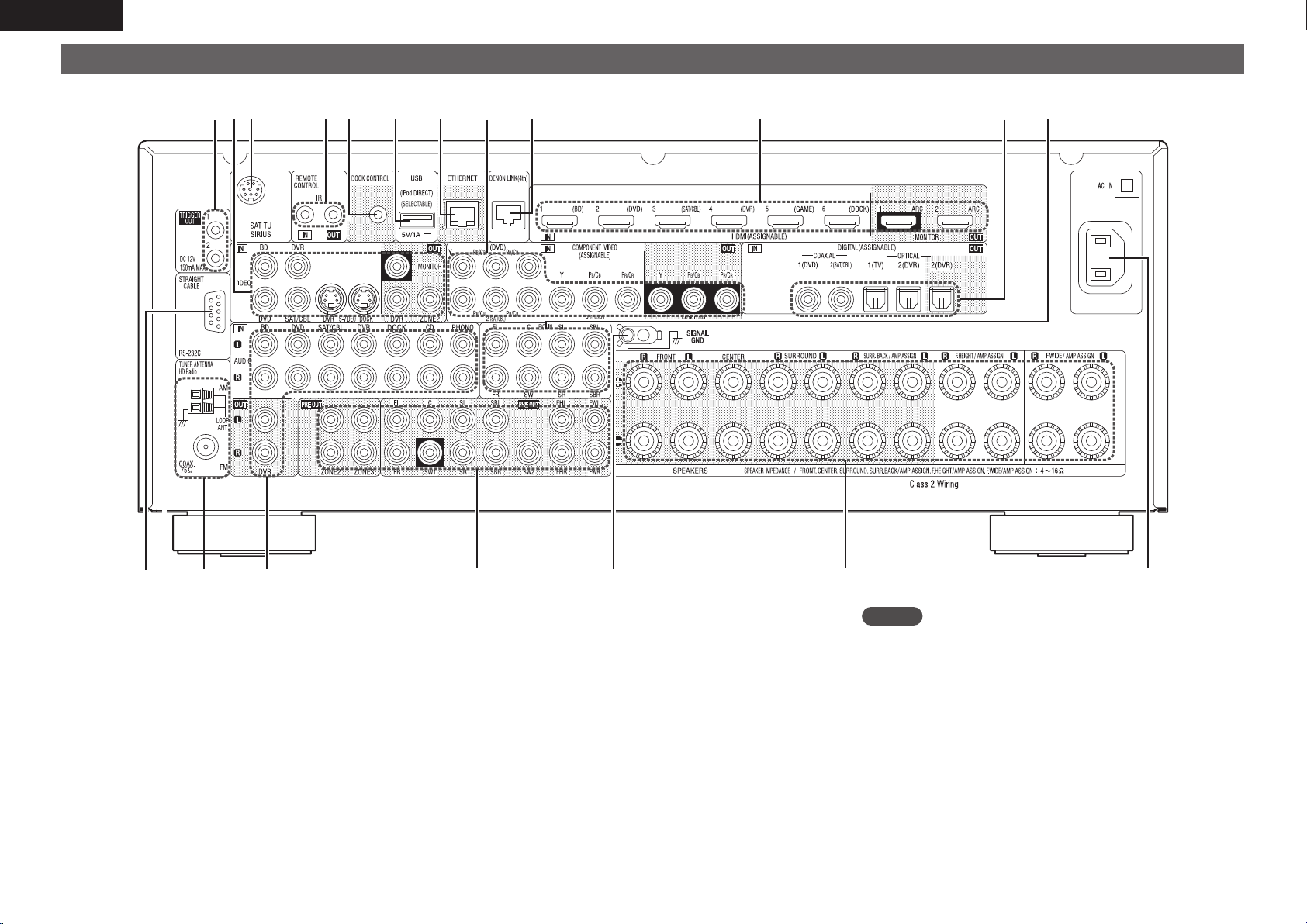
122
ENGLISH
Rear panel
See the page indicated in parentheses ( ).
Q0
q w
e r t uy
Q2
Q1
o i
Q9 Q8 Q7 Q6 Q3Q4Q5
q RS-232C connector ·································································· (27)
w HD Radio antenna terminals ·················································· (23)
e Analog audio connectors ·····································(18 – 21, 24, 25)
r PRE OUT connectors ········································(6, 25, 56 – 62, 72)
t SIGNAL GND terminal ···························································· (24)
y Speaker terminals ····················································(5, 6, 56 – 62)
u AC inlet (AC IN) ·········································································· (6)
i EXT.IN connectors ··································································· (25)
o Digital audio connectors ··················································(18 – 20)
Q0 HDMI connectors ································································· (6, 17)
Q1 DENON LINK connector ·························································· (25)
Q2 COMPONENT VIDEO connectors ····································(18 – 20)
Q3 ETHERNET connector ····························································· (26)
Q4 USB/iPod port ········································································· (22)
Q5 DOCK CONTROL jack ······························································ (21)
Q6 REMOTE CONTROL jacks ······················································· (27)
Q7 SIRIUS connector ···································································· (23)
Q8 S-VIDEO/VIDEO connectors ············································(18 – 21)
Q9 TRIGGER OUT jacks ································································ (27)
NOTE
Do not touch the inner pins of the connectors on the rear panel.
Electrostatic discharge may cause permanent damage to the unit.
1.AVRA100E3_ENG_1st_0824.indd 122 2010/08/26 17:48:30
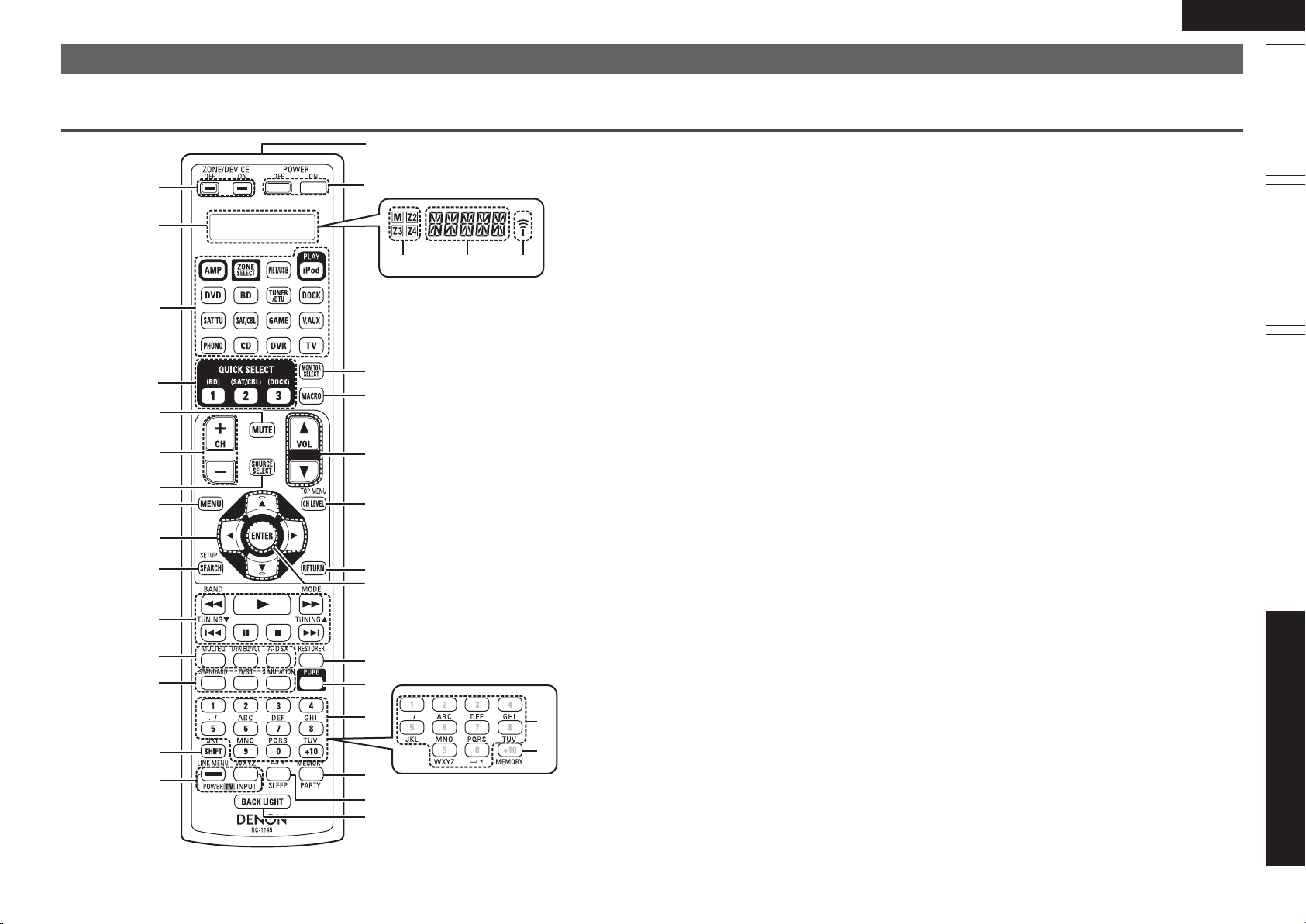
123
Basic versionSimple version Advanced version
ENGLISH
Information
Remote control unit
For buttons not explained here, see the page indicated in parentheses ( ).
Main remote control unit (RC-1145)
q
w
e
r
t
y
u
i
o
Q0
Q1
Q2
Q3
Q4
Q5
W3
W5
W6
W2
Q9
Q8
W4
W1
W0
Q7
Q6
q w e
E0
E1
W7
W8
W9
q ZONE/DEVICE power buttons ·········· (73, 111)
w Display
q Zone select indicators ·························· (108)
w Operation mode indicator ····················· (108)
e Signal transmission indicator
e Input source select buttons ················· (28, 73)
r QUICK SELECT buttons ······················· (67, 74)
t Muting button (MUTE) ·················· (13, 29, 73)
y Channel buttons (CH) ············· (34, 36, 39, 109)
u SOURCE SELECT button ··························· (28)
i MENU button ·············································· (80)
o Cursor buttons (uio p) ·················· (76 – 80)
Q0 SEARCH button
··········(30 – 32, 34 – 37, 40 – 43, 45, 47, 49, 79)
Q1 System buttons
····················(30 – 32, 40 – 43, 45, 47 – 49, 111)
• Search buttons (6, 7)
• Skip buttons (8, 9)
• Play button (1)
• Pause button (3)
• Stop button (2)
Tuner system buttons ························ (33 – 35)
• FM/AM band switching button (BAND)
• Tuning mode button (MODE)
• Tuning up / Tuning down buttons
(TUNING df)
Q2 Audyssey buttons ································ (89, 90)
• MULTEQ
®
XT 32 button (MULTEQ)
• Dynamic EQ
®
/DYNAMIC VOLUME
®
button
(DYN EQ/VOL)
• Audyssey DSX™ button (A-DSX)
Q3 Surround mode buttons ···················· (50 – 52)
• STANDARD button
• Direct / Stereo button (D/ST)
• DSP simulation button (SIMULATION)
Q4 SHIFT button ····························· (34, 36, 39, 78)
Q5 TV operation buttons
(TV POWER / INPUT) ······························ (111)
Q6 Remote control signal transmitter ········· (124)
Q7 Power buttons (POWER ON / OFF) ······ (7, 13)
Q8 Monitor select button
(MONITOR SELECT) ··································· (17)
Q9 MACRO button ································· (113, 114)
W0 Master volume control buttons
(VOL) ······················································ (28, 73)
W1 Channel level button (CH LEVEL) ············· (66)
W2 RETURN button ·········································· (80)
W3 ENTER button ····································· (77 – 80)
W4 RESTORER button ······································ (92)
W5 Pure direct button (PURE) ························· (52)
W6 Number buttons
··················(34 – 37, 40 – 43, 47, 49, 109 – 111)
W7 Character buttons ······································ (78)
W8 MEMORY button ···························· (34, 36, 39)
W9 PARTY button ············································· (68)
E0 SLEEP button ········································ (66, 74)
E1 BACK LIGHT button
When you press this button, the backlight of the
remote control unit lights for 10 seconds.
1.AVRA100E3_ENG_1st_0824.indd 123 2010/08/26 17:48:30
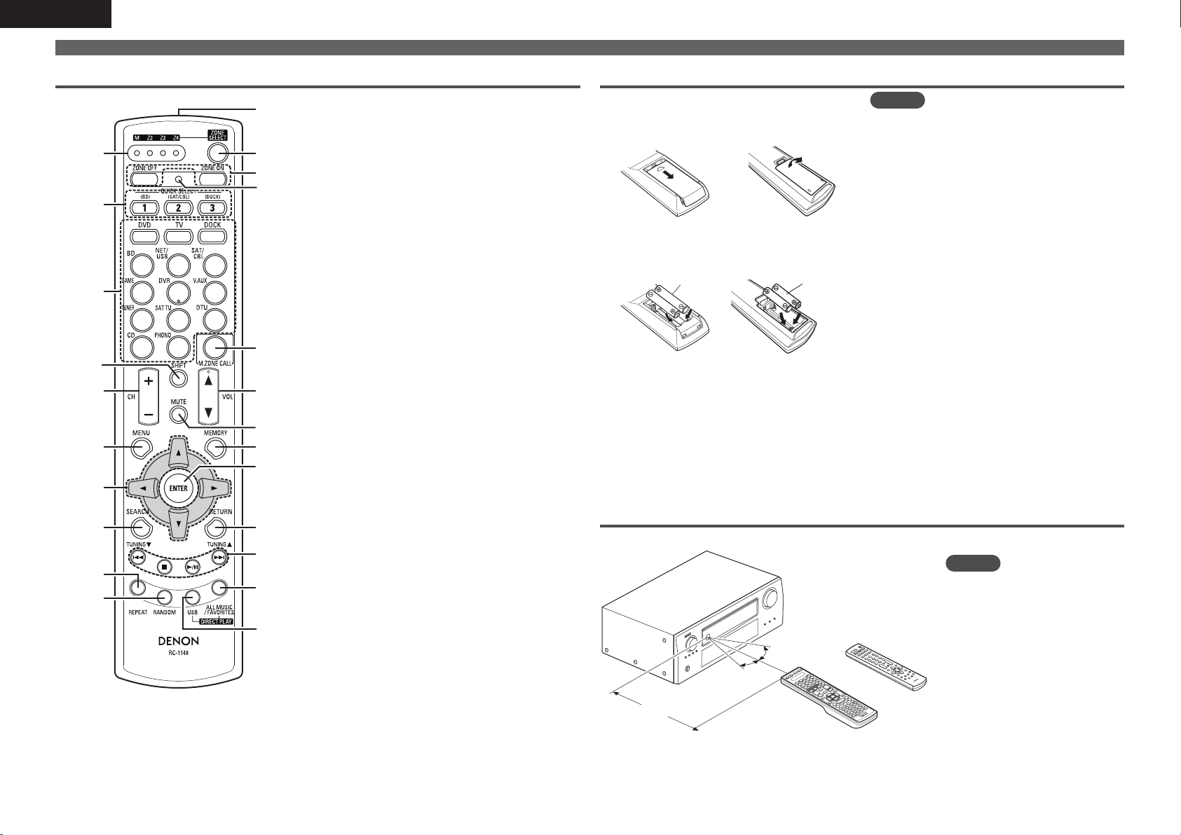
124
ENGLISH
NOTE
• Insert the specified batteries in the remote control
unit.
• Replace the batteries with new ones if the set
does not operate even when the remote control
unit is operated close to the unit. (The supplied
batteries are only for verifying operation.)
• When inserting the batteries, be sure to do so in
the proper direction, following the q and w marks
in the battery compartment.
• To prevent damage or leakage of battery fluid:
• Do not use a new battery together with an old
one.
• Do not use two different types of batteries.
• Do not attempt to charge dry batteries.
• Do not short-circuit, disassemble, heat or
dispose of batteries in flames.
• Do not keep the battery in a place exposed to
direct sunlight or in places with extremely high
temperatures, such as near a heater.
• If the battery fluid should leak, carefully wipe the
fluid off the inside of the battery compartment
and insert new batteries.
• Remove the batteries from the remote control
unit if it will not be in use for long periods.
• Used batteries should be disposed of in
accordance with the local regulations regarding
battery disposal.
Remote control unit
Inserting the batteries
q Slide the rear lid in the direction of the arrow
and remove it.
(RC-1145) (RC-1148)
w Load the two batteries properly as indicated by
the marks in the battery compartment.
R6/AA
(RC-1145) (RC-1148)
R03/AAA
e Put the rear cover back on.
Sub remote control unit (RC-1148)
q
t
r
y
i
o
Q0
u
e
w
Q6
Q5
Q8
W0
W1
W2
W3
Q9
Q7
Q2
Q3
Q4
Q1
q Zone indicators ········································· (116)
w QUICK SELECT buttons ······················· (67, 74)
e Input source select buttons ······· (28, 116, 117)
r SHIFT button ····················· (34, 36, 39, 78, 117)
t Channel buttons (CH) ····· (34, 36, 39, 109, 117)
y MENU button ···························· (80, 116 – 118)
u Cursor buttons
(uio p) ····························· (77 – 80, 116, 117)
i SEARCH button ·······(30 – 32, 34 – 37, 40 – 43,
45, 47, 49, 79, 116, 117)
o REPEAT button ······························· (116 – 118)
Q0 RANDOM button ···························· (116 – 118)
Q1 Remote control signal transmitter ········· (124)
Q2 ZONE SELECT button ···················· (116 – 118)
Q3 Zone power on/off buttons
(ZONE ON, ZONE OFF) ······························· (73)
Q4 Advanced setup button ··························· (118)
Q5 MAIN ZONE call button
(M.ZONE CALL) ········································· (118)
Q6 Master volume control buttons
(VOL) ······················································ (28, 73)
Q7 Muting button (MUTE) ·················· (13, 29, 73)
Q8 MEMORY button ·························· (34, 36, 117)
Q9 ENTER button ····················· (77 – 80, 116, 117)
W0 RETURN button ·························· (80, 116, 117)
W1 System buttons
·····(30 – 32 40 – 43, 45, 47 – 49, 111, 116, 117)
• Skip buttons (8, 9)
• Stop button (2)
• Play/Pause button (1/3)
Tuner system buttons ················ (33 – 35, 117)
• Tuning up / Tuning down buttons
(TUNING df)
W2 ALL MUSIC/FAVORITES
(DIRECT PLAY) button ··················· (116 – 118)
W3 USB (DIRECT PLAY) button ··········· (116 – 118)
Operating range of the remote control unit
Point the remote control unit at the remote sensor when operating it.
30°
30°
or
(RC-1148)
(RC-1145)
Approx. 23 ft /7 m
NOTE
The set may function improperly
or the remote control unit may not
operate if the remote control sensor
is exposed to direct sunlight, strong
artificial light from an inverter type
fluorescent lamp or infrared light.
1.AVRA100E3_ENG_1st_0824.indd 124 2010/08/26 17:48:30
125
Basic versionSimple version Advanced version
ENGLISH
Information
Other information
n Trademark information (vpage125)
n Surround (vpage126)
n Relationship between video signals and monitor
output (vpage131)
n Explanation of terms (vpage132)
Trademark information
This product uses the following technologies:
Manufactured under license from
Dolby Laboratories. “Dolby”, “Pro
Logic” and the double-D symbol are
trademarks of Dolby Laboratories.
Manufactured under license
under U.S. Patent #’s: 5,451,942;
5,956,674; 5,974,380; 5,978,762;
6,226,616; 6,487,535; 7,212,872;
7,333,929; 7,392,195; 7,272,567 &
other U.S. and worldwide patents
issued & pending. DTS and the
Symbol are registered trademarks,
& DTS-HD, DTS-HD Master Audio,
and the DTS logos are trademarks of
DTS, Inc. Product includes software.
© DTS, Inc. All Rights Reserved.
HDMI, the HDMI Logo and High-
Defi nition Multimedia Interface are
trademarks or registered trademarks
of HDMI Licensing LLC in the United
States and other countries.
Manufactured under license from
Audyssey Laboratories™. U.S. and
foreign patents pending. Audyssey
MultEQ
®
XT 32 is a registered
trademark of Audyssey Laboratories.
Audyssey Dynamic EQ
®
is a
registered trademark of Audyssey
Laboratories. Audyssey Dynamic
Volume
®
is a registered trademark
of Audyssey Laboratories. Audyssey
DSX™ is a trademark of Audyssey
Laboratories.
Microsoft, HDCD, and the HDCD
logo are trademarks or registered
trademarks of Microsoft Corporation
in the United States and/or other
countries.
SIRIUS, XM and all related marks and
logos are trademarks of Sirius XM
Radio Inc. and its subsidiaries. All
rights reserved.
Service not available in Alaska and
Hawaii.
HD Radio™ Technology Manufactured
Under License From iBiquity Digital
Corp. U.S. and Foreign Patents.
HD Radio™ and the HD Radio logo
are proprietary trademarks of iBiquity
Digital Corp.
“Made for iPod” and “Made for
iPhone” mean that an electronic
accessory has been designed to
connect specifi cally to iPod, or
iPhone, respectively, and has been
certifi ed by the developer to meet
Apple performance standards.
Apple is not responsible for
the operation of this device or
its compliance with safety and
regulatory standards. Please note
that the use of this accessory with
iPod, or iPhone, may affect wireless
performance.
iPhone, iPod, iPod classic, iPod nano,
iPod shuffl e, and iPod touch are
trademarks of Apple Inc., registered
in the U.S. and other countries.
• Individual users are permitted to
use iPhone, iPod, iPod classic,
iPod nano, iPod shuffl e, and iPod
touch for private copy and playback
of non-copyrighted contents and
contents whose copy and playback
is permitted by law. Copyright
infringement is prohibited by law.
Windows Media and the Windows
logo are trademarks or registered
trademarks of Microsoft Corporation
in the United States and/or other
countries.
This item incorporates copy protection technology that is protected
by U.S. patents and other intellectual property rights of Rovi
Corporation. Reverse engineering and disassembly are prohibited.
1.AVRA100E3_ENG_1st_0824.indd 125 2010/08/26 17:48:31
126
ENGLISH
Surround
This unit is equipped with a digital signal processing circuit that lets you play program sources in the surround mode to achieve the same sense of presence as in a movie theater.
Surround modes and parameters
This table shows the speakers that can be used in each surround mode and the surround parameters adjustable in each surround mode.
Symbols in the table
S This indicates the audio output channels or surround parameters that can be set.
D This indicates the audio output channels. The output channels depend on the settings of “Speaker Config.” (vpage95).
Surround mode (vpage50)
Channel output
Surround Parameters (vpage86)
Front
L/R
Center
Surround
L/R
Surround back
L/R
Front height
L/R
Front wide
L/R
Subwoofer
Mode
(vpage86)
Cinema EQ.
(vpage86)
DRC
z14z17
(vpage86)
D. COMP
z15z17
(vpage86)
LFE
z16z17
(vpage87)
Delay Time
(vpage87)
DIRECT/PURE DIRECT (2-channel)
z1
S D
z9
S S
DIRECT/PURE DIRECT (Multi-channel)
z1
S D D D
z3
D
z3
D
z3
D S S S
DSD DIRECT (2-channel)
S
DSD DIRECT (Multi-channel)
S D D D
STEREO
S D S S S
EXT.IN/PURE DIRECT EXT
z2
S D D D D
MULTI CH IN
S D D D D
z4
D S S
WIDE SCREEN
S D D D D
z5
D
z6
D S S S S
DOLBY PRO LOGIC gz S D D D D D S
z10
S S S
DOLBY PRO LOGIC gx S D D D D S S
z11
S S
DOLBY PRO LOGIC g S D D D S S
z12
S S
DOLBY PRO LOGIC
S D D D S S
z12
S S
DOLBY PRO LOGIC gx A-DSX S D D D D
z7
D
z8
D S S
z11
S S
DOLBY PRO LOGIC g A-DSX S D D D
z7
D
z8
D S S
z12
S S
DOLBY PRO LOGIC A-DSX
S D D D
z7
D
z8
D S S
z12
S S
DTS NEO:6
S D D D D S S
z11
S S
DTS NEO:6 A-DSX
S D D D D
z7
D
z8
D S S
z11
S S
Audyssey DSX
S D D D D
z7
D
z8
D S
z13
S S S
DOLBY DIGITAL
S D D D D
z4
D S
z13
S S
DOLBY DIGITAL Plus
S D D D D
z4
D S
z13
S S
DOLBY TrueHD
S D D D D
z4
D S
z13
S S
DTS SURROUND
S D D D D
z4
D S
z13
S S
DTS 96/24
S D D D D
z4
D S
z13
S S
DTS-HD
S D D D D
z4
D S
z13
S S
DTS Express
S D D D D
z4
D S
z13
S S
MULTI CH STEREO
S D D D
D
z5
D
z6
D S S
SUPER STADIUM
S D D D D
z5
D
z6
D S S S
ROCK ARENA
S D D D D
z5
D
z6
D S S S
JAZZ CLUB
S D D D D
z5
D
z6
D S S S
CLASSIC CONCERT
S D D D D
z5
D
z6
D S S S
MONO MOVIE
S D D D D
z5
D
z6
D S S S
VIDEO GAME
S D D D D
z5
D
z6
D S S S
MATRIX
S D D D D
z5
D
z6
D S S S S
VIRTUAL
S D
z9
S S S
z1 During playback in PURE DIRECT mode, the surround parameters are the same as in DIRECT mode.
z2 During playback in PURE DIRECT EXT mode, the surround parameters are the same as in EXT.IN mode.
z3 A signal for each channel contained in an input signal is output as audio.
z4 If “Surround Parameters” – “PLgz Height” (vpage88) is set to “ON”, sound is output from the front height
speakers.
z5 If “Surround Parameters” – “Speaker” (vpage88) is set to “Height” or “Height/Wide”, sound is output from the
front height speakers.
z6 If “Surround Parameters” – “Speaker” (vpage88) is set to “Wide” or “Height/Wide”, sound is output from the
front wide speakers.
z7 If “Audyssey DSX” (vpage90) is set to “ON–Height–” or “ON–Height/Wide–”, sound is output from the front
height speakers.
z8 If “Audyssey DSX” (vpage90) is set to “ON–Wide–” or “ON–Height/Wide–”, sound is output from the front
wide speakers.
z9 Only when “Subwoofer Mode” is set to “LFE+Main” (vpage96), sound is output from the subwoofer.
z10 If this surround mode is selected, only the “Height” mode setting is available for “Surround Parameters” –
“Mode” (vpage86).
z11 This item can be selected when “Surround Parameters” – “Mode” (vpage86) is set to “Cinema”.
z12 This item can be selected when “Surround Parameters” – “Mode” (vpage86) is set to “Cinema” or “Pro Logic”.
z13 This item cannot be set when “Surround Parameters” – “Surround Back” (vpage87) is set to “PLgx Music”.
z14 This item can be selected when a Dolby TrueHD signal is played.
z15 This item can be selected when a Dolby Digital or DTS signal is played.
z16 This item can be selected when a Dolby Digital or DTS signal or DVD-Audio is played.
z17 This item cannot be set when “Dolby Volume” is set to “ON”.
1.AVRA100E3_ENG_1st_0824.indd 126 2010/08/26 17:48:31

127
Basic versionSimple version Advanced version
ENGLISH
Information
Surround
Surround mode (vpage50)
Surround Parameters (vpage86)
Effect
(vpage88)
Effect Level
(vpage88)
Room Size
(vpage88)
AFDM
z11
(vpage87)
Surround Back
(vpage87)
PLgz Height
z18
(vpage88)
Height Gain
z19
(vpage88)
Speaker
(vpage88)
Subwoofer
(vpage88)
PRO LOGIC g/gx Music mode only
NEO:6 Music
mode only
Panorama
(vpage87)
Dimension
(vpage87)
Center Width
(vpage87)
Center Image
(vpage87)
DIRECT/PURE DIRECT (2-channel)
z1
S
z9
DIRECT/PURE DIRECT (Multi-channel)
z1
DSD DIRECT (2-channel)
DSD DIRECT (Multi-channel)
STEREO
EXT.IN/PURE DIRECT EXT
z2
MULTI CH IN
S S S S
WIDE SCREEN
S S S
DOLBY PRO LOGIC gz S S
DOLBY PRO LOGIC gx S S S S S
DOLBY PRO LOGIC g S S S S S
DOLBY PRO LOGIC
S S
DOLBY PRO LOGIC gx A-DSX S S S S
DOLBY PRO LOGIC g A-DSX S S S S
DOLBY PRO LOGIC A-DSX
S
DTS NEO:6
S S
DTS NEO:6 A-DSX
S S
Audyssey DSX
S S
DOLBY DIGITAL
S S S
DOLBY DIGITAL Plus
S S S
DOLBY TrueHD
S S S
DTS SURROUND
S S S
DTS 96/24
S S S
DTS-HD
S S S
DTS Express
S S S
MULTI CH STEREO
SUPER STADIUM
S S
ROCK ARENA
S S S
JAZZ CLUB
S S S
CLASSIC CONCERT
S S S
MONO MOVIE
S S S
VIDEO GAME
S S S
MATRIX
S
VIRTUAL
z1 During playback in PURE DIRECT mode, the surround parameters are the same as in DIRECT mode.
z2 During playback in PURE DIRECT EXT mode, the surround parameters are the same as in EXT.IN mode.
z9 Only when “Subwoofer Mode” is set to “LFE+Main” (vpage96), sound is output from the subwoofer.
z11 This item can be selected when a Dolby Digital or DTS signal or DVD-Audio is played.
z18 If “Speaker Config.” – “Front Height” (vpage96) is set to “None”, this item cannot be selected.
z19 This item can be selected when “Surround Parameters” – “PLgz Height” (vpage88) is set to “ON”.
1.AVRA100E3_ENG_1st_0824.indd 127 2010/08/26 17:48:31
128
ENGLISH
Surround
Surround mode (vpage50)
Subwoofer Att.
(vpage88)
Tone
z20
(vpage88)
Audyssey Settings (vpage89) A-DSX Soundstage (vpage90) Dolby Volume (vpage91)
RESTORER
z29
(vpage92)
MultEQ
®
XT 32
(vpage89)
Dynamic EQ
®
z21
(vpage89)
Dynamic
Volume
®
z22
(vpage90)
Audyssey DSX™
z25
(vpage90)
Stage Height
z26
(vpage90)
Stage Wide
z27
(vpage90)
Dolby Volume
(vpage91)
Volume Leveler
z28
(vpage91)
Volume Modeler
z28
(vpage91)
DIRECT/PURE DIRECT (2-channel)
z1
DIRECT/PURE DIRECT (Multi-channel)
z1
DSD DIRECT (2-channel)
DSD DIRECT (Multi-channel)
STEREO
S S S S S S S S
EXT.IN/PURE DIRECT EXT
z2
S
MULTI CH IN
S S S S S S S S
WIDE SCREEN
S S S S S S S S
DOLBY PRO LOGIC gz S S S S S S S S
DOLBY PRO LOGIC gx S S S S S S S S S
DOLBY PRO LOGIC g S S S S S S S S S
DOLBY PRO LOGIC
S S S S S S S S S
DOLBY PRO LOGIC gx A-DSX S S S S S S S S S S S
DOLBY PRO LOGIC g A-DSX S S S S S S S S S S S
DOLBY PRO LOGIC A-DSX
S S S S S S S S S S S
DTS NEO:6
S S S S S S S S S
DTS NEO:6 A-DSX
S S S S S S S S S S S
Audyssey DSX
S S S S S S S S S S
DOLBY DIGITAL
S S S S S S S S
DOLBY DIGITAL Plus
S S S S S S S S
DOLBY TrueHD
S S S S S S S S
DTS SURROUND
S S S S S S S S
DTS 96/24
S S S S S S S S
DTS-HD
S S S S S S S S
DTS Express
S S S S S S S S
MULTI CH STEREO
S S S S S S S S
SUPER STADIUM
D
z23
S S S S S S S
ROCK ARENA
D
z24
S S S S S S S
JAZZ CLUB
S S S S S S S S
CLASSIC CONCERT
S S S S S S S S
MONO MOVIE
S S S S S S S S
VIDEO GAME
S S S S S S S S
MATRIX
S S S S S S S S
VIRTUAL
S S S S S S S S
z1 During playback in PURE DIRECT mode, the surround parameters are the same as in DIRECT mode.
z
2 During playback in PURE DIRECT EXT mode, the surround parameters are the same as in EXT.IN mode.
z20 This item cannot be set when “Dynamic EQ” (vpage89) is set to “ON” or “Dolby Volume” is set to
“ON”.
z21 This item cannot be set when “MultEQ XT 32” (vpage89) is set to “OFF” or “Manual”.
z22 This item cannot be set when “Dynamic EQ” (vpage89) is set to “OFF”.
z23 In this surround mode, bass is +6 dB, and treble is +4 dB. (Default)
z24 In this surround mode, bass is +6 dB, and treble is 0 dB. (Default)
z25 This item can not be selected when “Surround Parameters” – “PLgz Height” (vpage88) is set to “ON”.
z26 This item can be selected when “A-DSX Soundstage” – “Audyssey DSX” is set to “ON-Height-” or “ON-
Height/Wide”.
z27 This item can be selected when “A-DSX Soundstage” – “Audyssey DSX” is set to “ON-Wide-” or “ON-
Height/Wide”.
z28 This item cannot be selected when "Dolby Volume" is set to "OFF".
z29 This item can be set when the input signal is analog, PCM 48 kHz or 44.1 kHz.
1.AVRA100E3_ENG_1st_0824.indd 128 2010/08/26 17:48:32

129
Basic versionSimple version Advanced version
ENGLISH
Information
Surround
n Types of input signals, and corresponding surround modes
This table shows the input signal that can be played in each surround mode. Check the audio signal of the input source then select the surround mode.
Symbols in the table
F This indicates the default surround mode.
D This indicates the surround mode that is fixed when “AFDM” (vpage87) is set to “ON”.
S This indicates the selectable surround mode.
Surround mode (vpage50)
NOTE
Input signal types and formats
ANALOG
PCM
(multi ch)
PCM
(2ch)
WMA/
MP3/
MPEG-4
AAC/FLAC/
WAV
DTS-HD
DTS-HD
LBR
DTS DOLBY DOLBY DIGITAL Super Audio CD
DTS-HD
Master
Audio
DTS-HD
High
Resolution
Audio
DTS
EXPRESS
DTS ES
DSCRT
(With Flag)
DTS ES
MTRX
(With Flag)
DTS
(5.1ch)
DTS 96/24
DOLBY
TrueHD
DOLBY
DIGITAL
Plus
DOLBY
DIGITAL EX
(With Flag)
DOLBY
DIGITAL EX
(With no
Flag)
DOLBY
DIGITAL
(5.1ch)
DOLBY
DIGITAL
(2ch)
DSD
(multi ch)
DSD
(2ch)
DTS SURROUND
DTS-HD MSTR
z4 F
DTS-HD HI RES
z4 F
DTS ES DSCRT6.1
z1z4 F D
DTS ES MTRX6.1
z1z4 F D
DTS SURROUND
z4 S S F
DTS 96/24
z4 F
DTS (–HD) + PLgx CINEMA z2z4 S S S S S S S
DTS (–HD) + PLgx MUSIC z1z4 S S S S S S S
DTS (–HD) + PLgz z3 S S S S S S S
DTS EXPRESS
z4 F
DTS (–HD) + NEO:6
z1z4 S S S S S S
DTS NEO:6 CINEMA
z5 S S S S S
DTS NEO:6 MUSIC
z5 S S S S S
DTS NEO:6 CINEMA A-DSX
z6 S S S S S
DTS NEO:6 MUSIC A-DSX
z6 S S S S S
Audyssey DSX
z6 S S S S S S S
DOLBY SURROUND
DOLBY TrueHD
z4 F
DOLBY DIGITAL+
z4 F
DOLBY DIGITAL EX
z1z4 S S S
DOLBY (D+) (HD) +EX
z1z4 S S
DOLBY DIGITAL
z4 S F F
DOLBY (D) (D+) (HD) +PLgx
CINEMA
z2z4 S S F D S S
DOLBY (D) (D+) (HD) +PLgx
MUSIC
z1z4 S S S S S
DOLBY (D) (D+) (HD) +PLgz z3 S S S S S
DOLBY PRO LOGIC gx CINEMA z1 S S S S S
DOLBY PRO LOGIC gx MUSIC z1 S S S S S
DOLBY PRO LOGIC gx GAME z1 S S S S S
DOLBY PRO LOGIC gz z3 S S S S S
z1 If “Speaker Config.” – “Surround Back” (vpage96) is set to “None”, this surround mode cannot be selected.
z2 If “Speaker Config.” – “Surround Back” (vpage96) is set to “1 spkr” or “None”, this surround mode cannot
be selected.
z3 If “Speaker Config.” – “Front Height” (vpage96) is set to “None”, this surround mode cannot be selected.
z4 The same was when “Audyssey DSX™” (vpage90) setting is set to “ON”.
z5 If “Speaker Config.” – “Center” and “Surround” is set to “None” or headphones are used, this surround mode cannot
be selected.
z6 If “Speaker Config.” – “Front Height”, “Front Wide” and “Center” is set to “None” or headphones are used, this
surround mode cannot be selected.
1.AVRA100E3_ENG_1st_0824.indd 129 2010/08/26 17:48:32
130
ENGLISH
Surround
Surround mode (vpage50)
NOTE
Input signal types and formats
ANALOG
PCM
(multi ch)
PCM
(2ch)
WMA/
MP3/
MPEG-4
AAC/FLAC/
WAV
DTS-HD DTS DOLBY DOLBY DIGITAL Super Audio CD
DTS-HD
Master
Audio
DTS-HD
High
Resolution
Audio
DTS
EXPRESS
DTS ES
DSCRT
(With Flag)
DTS ES
MTRX
(With Flag)
DTS
(5.1ch)
DTS 96/24
DOLBY
TrueHD
DOLBY
DIGITAL
Plus
DOLBY
DIGITAL EX
(With Flag)
DOLBY
DIGITAL EX
(With no
Flag)
DOLBY
DIGITAL
(5.1ch)
DOLBY
DIGITAL
(2ch)
DSD
(multi ch)
DSD
(2ch)
DOLBY SURROUND
DOLBY PRO LOGIC g CINEMA z5 S S S S S
DOLBY PRO LOGIC g MUSIC z5 S S S S S
DOLBY PRO LOGIC g GAME z5 S S S S S
DOLBY PRO LOGIC
z5 S S S S S
DOLBY PRO LOGIC g CINEMA
A-DSX
z6 S S S S S
DOLBY PRO LOGIC g MUSIC
A-DSX
z6 S S S S S
DOLBY PRO LOGIC g GAME
A-DSX
z6 S S S S S
DOLBY PRO LOGIC A-DSX
z6 S S S S S
Audyssey DSX
z6 S S S S S
MULTI CH IN
MULTI CH IN
z4 F F
MULTI CH IN + PLgx CINEMA z2z4 S S
MULTI CH IN + PLgx MUSIC z1z4 S S
MULTI CH IN + PLgz z3 S S
MULTI CH IN + Dolby EX
z4 S S
MULTI CH IN 7.1
z4 F D (7.1)
Audyssey DSX
z6 S S
DIRECT
DIRECT
S S S S S S S S S S S S S S S S S S S
DSD DIRECT
S S
PURE DIRECT
PURE DIRECT
S S S S S S S S S S S S S S S S S S S
DSP SIMULATION
MULTI CH STEREO
S S S S S S S S S S S S S S S S S S S
WIDE SCREEN
S S S S S S S S S S S S S S S S S S S
SUPER STADIUM
S S S S S S S S S S S S S S S S S S S
ROCK ARENA
S S S S S S S S S S S S S S S S S S S
JAZZ CLUB
S S S S S S S S S S S S S S S S S S S
CLASSIC CONCERT
S S S S S S S S S S S S S S S S S S S
MONO MOVIE
S S S S S S S S S S S S S S S S S S S
VIDEO GAME
S S S S S S S S S S S
S S S S S S S S
MATRIX
S S S S S S S S S S S S S S S S S S S
VIRTUAL
S S S S S S S S S S S S S S S S S S S
STEREO
STEREO
F S F F S S S S S S S S S S S S S S F
z1 If “Speaker Config.” – “Surround Back” (vpage96) is set to “None”, this surround mode cannot be selected.
z2 If “Speaker Config.” – “Surround Back” (vpage96) is set to “1 spkr” or “None”, this surround mode cannot be selected.
z3 If “Speaker Config.” – “Front Height” (vpage96) is set to “None”, this surround mode cannot be selected.
z4 The same was when “Audyssey DSX™” (vpage90) setting is set to “ON”.
z5 If “Speaker Config.” – “Center” and “Surround” is set to “None” or headphones are used, this surround mode cannot be selected.
z6 If “Speaker Config.” – “Front Height”, “Front Wide” and “Center” is set to “None” or headphones are used, this surround mode cannot be selected.
1.AVRA100E3_ENG_1st_0824.indd 130 2010/08/26 17:48:32
131
Basic versionSimple version Advanced version
ENGLISH
Information
Relationship between video signals and monitor output
MAIN ZONE MONITOR OUT
Video Convert
Input Signals Output Signals Menu displayed
HDMI COMPONENT S-VIDEO VIDEO HDMI COMPONENT VIDEO HDMI COMPONENT VIDEO
ON/OFF
A A A A A A A
Only the menu is displayed
ON
A A A S
VIDEO VIDEO VIDEO
S (VIDEO) S (VIDEO) S (VIDEO)
ON
A A S A
S-VIDEO S-VIDEO S-VIDEO
S (S-VIDEO) S (S-VIDEO) S (S-VIDEO)
ON
A A S S
ON
A S (1080p) A A
COMPONENT COMPONENT
A
S (COMPONENT)
A (COMPONENT)
z2
A
z2
ON
A S (1080i – 480p) A A
S (COMPONENT)
A
ON
A S (480i/576i) A A
COMPONENT
S (COMPONENT)
ON
A S (1080p) A S
VIDEO
A (COMPONENT) A (VIDEO)
ON
z1
A S (1080p) A S A S (VIDEO) S (VIDEO)
ON
A S (1080i – 480p) A S
S (COMPONENT)
S (COMPONENT)
A (VIDEO)
ON
A S (480i/576i) A S
COMPONENT
S (COMPONENT)
ON
A S (1080p) S A
S-VIDEO
A (COMPONENT) A (S-VIDEO)
ON
z1
A S (1080p) S A A S (S-VIDEO) S (S-VIDEO)
ON
A S (1080i – 480p) S A
S (COMPONENT)
S (COMPONENT)
A (S-VIDEO)
ON
A S (480i/576i) S A
COMPONENT
S (COMPONENT)
ON
A S (1080p) S S
S-VIDEO
A (COMPONENT) A (S-VIDEO)
ON
z1
A S (1080p) S S A S (S-VIDEO) S (S-VIDEO)
ON
A S (1080i – 480p) S S
S (COMPONENT) S (COMPONENT)
A (S-VIDEO)
ON
A S (480i/576i) S S
COMPONENT
S (COMPONENT)
ON
S A A A
HDMI
A
A
S (HDMI)
A
z2
A
z2
ON
S A A S
VIDEO
A (VIDEO)
z2
ON
S A S A
S-VIDEO
A (S-VIDEO)
z2
ON
S A S S
ON
S S A A
COMPONENT
A
A (COMPONENT)
z2
A
z2
ON
S S A S
VIDEO
A (VIDEO)
z2
ON
S S S A
S-VIDEO
A (S-VIDEO)
z2
ON
S S S S
OFF
A A A S
A
A
VIDEO
Only the menu is displayed
OFF
A A S A
S-VIDEO
OFF
A A S S
S-VIDEO
OFF
A S A A
COMPONENT
A
OFF
A S A S
VIDEO
OFF
A S S A
S-VIDEO
OFF
A S S S
S-VIDEO
OFF
S A A A
HDMI
A
A
OFF
S A A S
VIDEO
OFF
S A S A
S-VIDEO
OFF
S A S S
S-VIDEO
OFF
S S A A
COMPONENT
A
OFF
S S A S
VIDEO
OFF
S S S A
S-VIDEO
OFF
S S S S
S-VIDEO
S Video signal input present
A No video signal input
z1 When no HDMI monitor is connected or the HDMI monitor’s power is not on
A No video signal output
S ( ) Superimposed on the picture indicated in ( ).
A ( ) Only the picture in ( ) is output.
A Neither the picture nor the menu is output.
z2 Only the menu is displayed when no HDMI monitor is
connected or the HDMI monitor’s power is not on.
NOTE
• If you operate the menu while playing back 3D video content,
the playback video is replaced by the menu screen. The playback
video is not displayed behind the menu screen.
• This unit does not show the status display while playing back 3D
video content.
• The main zone video conversion function is compatible with the following formats: NTSC, PAL,
SECAM, NTSC4.43, PAL-N, PAL-M and PAL-60.
• When SECAM signals of video input are up-converted, the signals are output in PAL format from
the S-Video and Video connectors.
• The menu display cannot be superimposed when x.v.Color, sYCC601 color, Adobe RGB color,
Adobe YCC601 color or computer resolution.
ZONE2 MONITOR OUT
Input Signals
Output
Signals
On-screen display
S-VIDEO VIDEO VIDEO VIDEO
A
A
A
Only the on-screen display
menu is displayed
A
S
VIDEO
S (VIDEO)
S
A
S-VIDEO
S (S-VIDEO)
S
S
S-VIDEO
S (S-VIDEO)
1.AVRA100E3_ENG_1st_0824.indd 131 2010/08/26 17:48:32

132
ENGLISH
Explanation of terms
A
Adobe RGB color, Adobe YCC601 color
Like x.v.Color, each of these color spaces defines
a palette of available colors that is larger than the
traditional RGB color model.
AL24 Processing Plus
AL24 Processing for All Channels
DENON has further developed its proprietary AL24
Processing, an analog waveform reproduction
technology, to support the 192 kHz sampling
frequency. AL24 Processing Plus, thoroughly
suppresses quantization noise associated with D/A
conversion of LPCM signals to reproduce the low-
level signals with optimum clarity that will bring out
all the delicate nuances of the music.
Equipped foe not only front left and right channels
but also for the surround left and right, center and
subwoofer channels.
Audyssey Dynamic Surround Expansion™
(A-DSX)
Realistic reproduction of sound relies on the
ability of audio systems to match human hearing
performance. Three key requirements are: (1)
frequency response, (2) dynamic range, and (3)
accurate spatial reproduction. The requirements for
frequency response have already been surpassed
with sampling rates that exceed human hearing.
The dynamic range limits of human perception
have also been met with current digital audio
systems operating capable of signal to noise ratios
that approach 120 dB. Accurate spatial sound
rendering, however, has not yet reached the limits
of perception as human perception relies on the
combination of sounds arriving from many more
directions than what 5.1-channel surround sound
systems provide. Audyssey DSX technology was
developed to overcome the spatial sound rendering
limitations faced by 5.1-channel surround sound
formats.
The ITU 5.1-channel channel standard recommends
three front loudspeakers and two rear loudspeakers.
The Left (L) and Right (R) front loudspeakers should
be placed at ±30° relative to the central listening
position. The Center (C) loudspeaker should be at
0° and the surround loudspeakers (SL, SR) should
be placed between 100° and 120°. All loudspeakers
must be equidistant from the center listening
position or compensated with time delay if that
is not possible. A separate low-frequency effects
(LFE) channel is used to reproduce additional bass
content from the subwoofer.
There are certain things that 5.1-channel surround
sound systems do well compared to 2-channel
stereo. For example, it is possible to move sounds
across the front seamlessly. It is also possible to
create ambience behind the listener. But 5.1 channel
surround systems do not provide enough channels
from which to render the required refl ected
sound components for a seamless and enveloping
soundstage. Unfortunately, the additional two back
surround channels in 7.1-channel systems are not
in the right place to provide a significant perceptual
improvement.
Adding more channels to a surround system is
not for special effects. Accurate spatial sound
reproduction requires rendering of directional
sound cues and non-directional ambient cues.
Refl ections arriving after the direct sound play a
critical role in the perception of soundstage width
and depth. To have the most impact, additional
surround channels should be used to control the
direction, time of arrival, and frequency response
of the refl ected sound to render an expanded
soundstage that reproduces sound with better
localization and envelopment than what 5.1-channel
systems provide.
Research in the perception of auditory source width
has shown that there are strong preferences in the
direction of refl ected sound and the perception of
soundstage width and spaciousness. The single
most important direction of side-wall refl ections
is ±60°. DSX provides a pair of Wide channels
(LW and RW) at ±60° with appropriate frequency
response and perceptual processing to match the
requirements of human hearing. In fact, the Wide
channels are much more critical in the presentation
of a realistic soundstage than then Back Surround
channels found in traditional 7.1-channel systems. A
more enveloping 7.1-channel system is one in which
Wide speakers are used instead of Back Surround
speakers. Adding surround channels behind the
listener has a very small impact compared to the
increase in envelopment and soundstage width that
the front wide channels will provide.
After side refl ections, the next most important
acoustical and perceptual cues come from refl
ections above the front stage. DSX provides a pair
of Height channels (LH and RH) at a ±45° azimuth
angle and elevated to a 45° angle in the median
plane.
In addition to creating new Wide and Height
channels, DSX also provides Surround Processing
to enhance the envelopment of the Surround and
Back Surround channels (if present). DSX Surround
Processing processes the standard surround signals
in the time and frequency domains to improve the
perceived sense of envelopment and blending with
the other speakers in the surround system.
Audyssey Dynamic Surround Expansion is a scalable
system that can adapt to the practical needs of the
user. The first level of surround stage enhancement
comes from adding the Wide channels. The second
level comes from adding the Height channels. If it
is practical to have both Wides and Heights then
the surround performance will be further enhanced.
DSX automatically reconfigures its processing to
optimize surround rendering over any number of
available speakers beyond that of 5.1-channel.
Audyssey Dynamic EQ
®
Audyssey Dynamic EQ solves the problem of
deteriorating sound quality as volume is decreased
by taking into account human perception and room
acoustics. Audyssey Dynamic EQ works in tandem
with Audyssey MultEQ XT 32 to provide well-
balanced sound for every listener at any volume
level.
Audyssey Dynamic Volume
®
Audyssey Dynamic Volume solves the problem of
large variations in volume level between television
programs, commercials, and between the soft and
loud passages of movies. Audyssey Dynamic EQ
is integrated into Dynamic Volume so that as the
playback volume is adjusted automatically, the
perceived bass response, tonal balance, surround
impression, and dialog clarity remain the same.
Audyssey MultEQ
®
XT 32
Audyssey MultEQ XT 32 is a room equalization
solution that calibrates any audio system so that
it can achieve optimum performance for every
listener in a large listening area. Based on several
room measurements, MultEQ XT 32 calculates an
equalization solution that corrects for both time
and frequency response problems in the listening
area and also performs a fully automated surround
system setup.
Auto Lip Sync
If you connect the receiver to a TV that supports the
Auto Lip Sync function, it can automatically correct
delay between the audio and video.
D
Deep Color
This technology allows expression of more number
of colors than the conventional 8 bits and can
reproduce colors close to natural ones without color
streak.
DENON LINK
DENON LINK is a unique digital, balanced transfer
type interface developed by DENON. It offers high
speed, high quality transfer of digital audio data
with low signal loss. It can be used together with
a DENON Blu-ray disc / DVD player equipped with
a special DENON LINK connector using a single
cable to enable playback with high sound quality.
It allows digital transfer of the 192 kHz/24 bit
2-channel digital signals of DVD-Audio discs, PCM
multi-channel signals, etc. Full-spec digital transfer
of the audio contents of Super Audio CD is possible
by connecting a player equipped for DENON LINK
3rd Edition.
During processing of DENON LINK, the
indicator of the display lights.
DENON LINK 4th uses the clock of the AV amplifier
connected by DENON LINK to achieve HDMI signal
transfer with low jitter when playing BD.
DLNA
DLNA and DLNA CERTIFIED are trademarks and/
or service marks of Digital Living Network Alliance.
Some contents may not be compatible with other
DLNA CERTIFIED™ products.
Dolby Digital
Dolby Digital is a multi-channel digital signal format
developed by Dolby Laboratories.
A total of 5.1 channels are played: 3 front channels
(“FL”, “FR” and “C”), 2 surround channels
(“SL” and “SR”) and the “LFE” channel for low
frequencies.
Because of this, there is no crosstalk between
channels and a realistic sound field with a “three-
dimensional” feeling (sense of distance, movement
and positioning) is achieved.
A realistic, powerful sense of presence is achieved
when playing movie sources in AV rooms as well.
1.AVRA100E3_ENG_1st_0824.indd 132 2010/08/26 17:48:32

133
Basic versionSimple version Advanced version
ENGLISH
Information
Dolby Digital EX
Dolby Digital EX is a 6.1-channel surround format
proposed by Dolby Laboratories that allows users
to enjoy in their homes the “DOLBY DIGITAL
SURROUND EX” audio format jointly developed by
Dolby Laboratories and Lucas Films.
The 6.1 channels of sound, including surround back
channels, provide improved sound positioning and
expression of space.
Dolby Digital Plus
Dolby Digital Plus is an improved Dolby Digital signal
format that is compatible with up to 7.1 channels
of discrete digital sound and also improves sound
quality thanks to extra data bit rate performance.
It is upwardly compatible with conventional Dolby
Digital, so it offers greater flexibility in response to
the source signal and the conditions of the playback
equipment.
Dolby TrueHD
Dolby TrueHD is a high definition audio technology
developed by Dolby Laboratories, using lossless
coding technology to faithfully reproduce the sound
of the studio master.
This format provides the facility to support up to
8 audio channels with a sampling frequency of
96kHz/24bit resolution and up to 6 audio channels
with a sampling frequency of 192kHz/24bit
resolution. Dolby TrueHD is adopted for applications
that put very high importance on sound quality.
Dolby Pro Logic g
Dolby Pro Logic g is a matrix decoding technology
developed by Dolby Laboratories.
Regular music such as that on CDs is encoded into
5 channels to achieve an excellent surround effect.
The surround channel signals are converted into
stereo and full band signals (with a frequency
response of 20 Hz to 20 kHz or greater) to create
a “three-dimensional” sound image offering a rich
sense of presence for all stereo sources.
Dolby Pro Logic gx
Dolby Pro Logic gx is a further improved version of
the Dolby Pro Logic g matrix decoding technology.
Audio signals recorded in 2 channels are decoded
to achieve a natural sound with up to 7.1 channels.
There are three modes: “Music” suited for playing
music, “Cinema” suited for playing movies, and
“Game” which is optimized for playing games.
Explanation of terms
Dolby Pro Logic gz
Dolby Pro Logic gz introduces a new dimension to
Home Entertainment through the addition of a pair
of front height channels. Compatible with stereo,
5.1-channel and 7.1-channel content, Dolby Pro
Logic gz provides enhanced spaciousness, depth
and dimension to movies, concert video and video
game playback while maintaining the full integrity
of the source mix.
Dolby Pro Logic gz identifies and decodes spatial
cues that occur naturally in all content, directing
this information to the front height channels,
complementing the performance of left and right
surround sound speakers. Content that is encoded
with Dolby Pro Logic gz height channel information
can be even more revealing, with perceptually
discrete height channel information bringing an
exciting new dimension to home entertainment.
Dolby Pro Logic gz, with front height channels is
also an ideal alternative for households that cannot
support the placement of back surround speakers
of a typical 7.1-channel system but may have
bookshelf space available to support the addition of
height speakers.
Dolby Volume
Automatically adjusts the volume that varies
depending on the contents and input source and
performs appropriate corrections of the frequency
characteristic.
Downmix
This function converts the number of channels of
surround audio to less number of channels and
plays back.
DTS
This is an abbreviation of Digital Theater System,
which is a digital audio system developed by DTS.
When playing back audio by connecting this system
with a device such as DTS amplifier, accurate sound
field position and realistic sound effect as if you are
in a movie theater can be obtained.
DTS 96/24
DTS 96/24 is a digital audio format enabling high
sound quality playback in 5.1 channels with a
sampling frequency of 96 kHz and 24 bit quantization
on DVD-Video.
DTS Digital Surround
DTS Digital Surround is the standard digital surround
format of DTS, Inc., compatible with a sampling
frequency of 44.1 or 48 kHz and up to 5.1 channels
of digital discrete surround sound.
DTS-ES™ Discrete 6.1
DTS-ES™ Discrete 6.1 is a 6.1-channel discrete
digital audio format adding a surround back (SB)
channel to the DTS digital surround sound.
Decoding of conventional 5.1-channel audio signals
is also possible according to the decoder.
DTS-ES™ Matrix 6.1
DTS-ES™ Matrix 6.1 is a 6.1-channel discrete digital
audio format inserting a surround back (SB) channel
to the DTS digital surround sound through matrix
encoding. Decoding of conventional 5.1-channel
audio signals is also possible according to the
decoder.
DTS Express
DTS Express is an audio format supporting low bit
rates (max. 5.1 channels, 24 to 256 kbps).
DTS-HD
This audio technology provides higher sound quality
and enhanced functionality than the conventional
DTS and is adopted as an optional audio for Blu-ray
Disc. This technology supports multi-channel, high
data transfer speed, high sampling frequency, and
lossless audio playback. Maximum 7.1-channels are
supported in Blu-ray Disc.
DTS-HD High Resolution Audio
DTS-HD High Resolution Audio is an improved
version of the conventional DTS, DTS-ES and
DTS 96/24 signals formats, compatible with
sampling frequencies of 96 or 48 kHz and up to
7.1 channels of discrete digital sound. High data
bit rate performance provides high quality sound.
This format is fully compatible with conventional
products, including conventional DTS digital
surround 5.1-channel data.
DTS-HD Master Audio
DTS-HD Master Audio is a lossless audio format
created by Digital Theater System (DTS). This
format provides the facility to support up to 8 audio
channels with a sampling frequency of 96kHz/24bit
resolution and up to 6 audio channels with a
sampling frequency of 192kHz/24bit resolution.
It is fully compatible with conventional products,
including conventional DTS digital surround
5.1-channel data.
DTS NEO:6™ Surround
DTS NEO:6™ is a matrix decoding technology
for achieving 6.1-channel surround playback
with 2-channel sources. It includes “DTS NEO:6
Cinema” suited for playing movies and “DTS
NEO:6 Music” suited for playing music.
Dynamic range
The difference between the maximum undistorted
sound level and the minimum discernible level
above the noise emitted by the device.
H
HDCD
HDCD
®
is an encoding/decoding technology that
greatly reduces the distortion that occurs upon
digital recording while maintaining compatibility
with the conventional CD format, thus expanding
the dynamic range and achieving a high resolution.
Conventional CDs and HDCD compatible CDs are
identified automatically to select the optimum
digital processing.
HDCP
When transmitting digital signals between devices,
this copyright protection technology encrypts
the signals to prevent content from being copied
without authorization.
HDMI
This is an abbreviation of High-Definition Multimedia
Interface, which is an AV digital interface that can
be connected to a TV or amplifier. Video signal and
audio signal can be connected using 1 cable.
L
LFE
This is an abbreviation of Low Frequency Effect,
which is an output channel that emphasizes
low frequency effect sound. Surround audio is
intensified by outputting 20 Hz to 120 Hz deep
bass.
M
MAIN ZONE
The room where this unit is placed is called the
MAIN ZONE .
MP3 (MPEG Audio Layer-3)
This is an internationally standardized audio data
compression scheme, using the “MPEG-1” video
compression standard. It compresses the data
volume to about one eleventh its original size while
maintaining sound quality equivalent to a music CD.
1.AVRA100E3_ENG_1st_0824.indd 133 2010/08/26 17:48:33

134
ENGLISH
Explanation of terms
MPEG (Moving Picture Experts Group), MPEG-2,
MPEG-4
These are the names for digital compression format
standards used for the encoding of video and audio.
Video standards include “MPEG-1 Video”, “MPEG-
2 Video”, “MPEG-4 Visual”, “MPEG-4 AVC”. Audio
standards include “MPEG-1 Audio”, “MPEG-2
Audio”, “MPEG-4 AAC”.
P
Progressive (sequential scanning)
This is a scanning system of video signal that
displays 1 frame of video as one image. Compared
to the interlace system, this system provides
images with less flickering and bleeding.
Protection Circuit
This is a function to prevent damage to
components within the power supply when an
abnormality such as an overload, excess voltage
occurs or temperature for any reason.
In this unit, the power indicator blinks and the unit
enters standby mode when an abnormality occurs.
S
Sampling frequency
Sampling involves taking a reading of a sound wave
(analog signal) at regular intervals and expressing
the height of the wave at each reading in digitized
format (producing a digital signal).
The number of readings taken in one second is
called the “sampling frequency”. The larger the
value, the closer the reproduced sound is to the
original.
Speaker impedance
This is an AC resistance value, indicated in Ω
(ohms). Greater power can be obtained with this
value smaller.
sYCC601 color
Like x.v.Color, each of these color spaces defines
a palette of available colors that is larger than the
traditional RGB color model.
V
vTuner
This is a free online content server for Internet
radio. Note that usage fees are included in upgrade
costs.
For inquiries about this service, visit the vTuner site
below.
vTuner website: http://www.radiodenon.com
This product is protected by certain intellectual
property rights of Nothing Else Matters Software
and BridgeCo. Use or distribution of such technology
outside of this product is prohibited without a
license from Nothing Else Matters Software and
BridgeCo or an authorized subsidiary.
W
Windows Media DRM
This is a copyright protection technology developed
by Microsoft.
Content providers are using the digital rights
management technology for Windows Media
contained in this device (WM-DRM) to protect
the integrity of their content (Secure Content) so
that their intellectual property, including copyright,
in such content is not misappropriated. This
device uses WM-DRM software to play Secure
Content (WM-DRM Software). If the security of
the WM-DRM Software in this device has been
compromised, owners of Secure Content (Secure
Content Owners) may request that Microsoft
revoke the WM-DRM Software’s right to acquire
new licenses to copy, display and/or play Secure
Content. Revocation does not alter the WM-DRM
Software’s ability to play unprotected content.
A list of revoked WM-DRM Software is sent to
your device whenever you download a license for
Secure Content from the Internet or from a PC.
Microsoft may, in conjunction with such license,
also download revocation list onto your device on
behalf of Secure Content Owners.
Windows Media Player Ver.11
This is a media player distributed free of charge by
Microsoft Corporation.
It can be used to play playlists created with
Windows Media Player Ver. 11 as well as files in
such formats as WMA, DRM WMA, MP3 and WAV.
WMA (Windows Media Audio)
This is audio compression technology developed
by Microsoft Corporation.
WMA data can be encoded using Windows
Media
®
Player Ver.7, 7.1, Windows Media
®
Player for Windows
®
XP and Windows Media
®
Player 9 Series.
To encode WMA files, only use applications
authorized by Microsoft Corporation. If you use
an unauthorized application, the file may not work
properly.
X
x.v.Color
This function lets HDTVs display colors more
accurately. It enables display with natural, vivid
colors. “x.v.Color” is a Sony registered trademark.
Z
ZONE2
This unit can operate in a room other than the room
where this unit is placed (MAIN ZONE) (ZONE2
playback). The room for ZONE2 playback is called
ZONE2.
ZONE3
This unit can operate in a room other than the room
where this unit is placed (MAIN ZONE) (ZONE3
playback). The room for ZONE3 playback is called
ZONE3.
1.AVRA100E3_ENG_1st_0824.indd 134 2010/08/26 17:48:33
135
Basic versionSimple version Advanced version
ENGLISH
Information
If a problem should arise, first check the following:
1. Are the connections correct?
2. Is the set being operated as described in the owner’s manual?
3. Are the other components operating properly?
If this unit does not operate properly, check the items listed in the table below. Should the problem persist,
there may be a malfunction.
In this case, disconnect the power immediately and contact your store of purchase.
GGeneralH
Symptom Cause/Solution Page
Power does not turn
on.
• Check whether the power plug is correctly inserted into the power
outlet.
• The protection circuit is active. Disconnect the power plug from
the electric outlet, wait 5 to 10 seconds and then insert it back
into the outlet.
6
5, 134
Display is off. • Set “Dimmer” on the menu to something other than “OFF”. 105
The power indicator
is blinking red
in intervals of
approximately 2
seconds.
• The temperature inside the unit has risen. Please turn off power
once, and re-apply the power after the temperature has fallen
sufficiently.
• Please re-install this unit in a place having good ventilation.
–
–
The power indicator
is blinking red
in intervals of
approximately 0.5
seconds.
• Please use speakers which have the specified impedance.
• The speaker cable has shorted (is touching). Firmly twist the core
wire in the speaker cable, and then re-connect it to the speaker
terminal.
5, 98
5
After turning on the
power, the power
indicator is blinking
red in intervals of
approximately 0.5
seconds.
• This unit amplifier circuit has failed. Turn off the power and please
contact the DENON service adviser.
–
Set does not operate
properly.
• Reset the microprocessor. 138
GVideoH
Symptom Cause/Solution Page
No picture appears. • Check the TV connection.
• Set the TV input correctly.
6
7
Troubleshooting
GAudioH
Symptom Cause/Solution Page
Audio is not output. • Check the connections for all devices.
• Check the speaker connections and configurations.
• Check whether the audio device power is turned on.
• Adjust the master volume.
• Cancel the mute mode.
• Select a suitable input source.
• Select a suitable input mode.
• Disconnect the headphones. No sound is output from the speakers
or the PRE OUT connectors when headphones are connected.
6, 17 – 26
5, 6,
54 – 62
–
13, 28
13, 29
28
84
120
No sound is
produced from
surround speaker.
• Check if the surround speakers are connected to the SURROUND
terminals.
–
No sound is
produced from
surround back
speaker.
• Check if “Amp Assign” is set appropriately in order to output
audio from the surround back speakers.
• Set “Speaker Config.” – “Surround Back” on the menu to
something other than “None”.
• Set “Surround Parameters” – “Surround Back” on the menu to
something other than “OFF”.
• Set the surround mode to something other than “STEREO”.
93
96
87
52
No sound is
produced from front
height speaker.
• Set “Surround Parameters” – “PLgz Height” on the menu to
“ON”.
• Check if “Amp Assign” is set appropriately in order to output
audio from the front height speakers.
• Set “Speaker Config.” – “Front Height” on the menu to something
other than “None”.
88
93
96
No sound is
produced from
subwoofer.
• Check the subwoofer connections.
• Turn on the subwoofer’s power.
• Set “Speaker Config.” – “Subwoofer” on the menu to “1spkr”
or “2spkrs”.
• If “Front” and “Center” for “Speaker Config.” are set to “Large”,
and “Subwoofer Mode” is set to “LFE”, no sound may be output
from the subwoofers, depending on the input signal or selected
surround mode.
6, 56
7
96
95, 96
DTS sound is not
output.
• Set “Decode Mode” on the menu to “Auto” or “DTS”. 84
Dolby TrueHD, DTS-
HD, Dolby Digital
Plus audio is not
output.
• Make HDMI connections. 17
Dolby PLg mode or
DTS NEO:6 mode
cannot be selected.
Or “Not Available” is
displayed when the
STANDARD button is
pressed.
• Check that “Speaker Config.” – “Center” or “Surround” is set
to other than “None”. If the speaker system is 2.0/2.1ch, this
surround mode cannot be selected.
• When headphones are used, STANDARD mode (Dolby PLg or
DTS NEO:6) cannot be selected.
96
–
1.AVRA100E3_ENG_1st_0824.indd 135 2010/08/26 17:48:33
136
ENGLISH
GHDMIH
Symptom Cause/Solution Page
No audio is
output with HDMI
connection.
• Check the connection of the HDMI connectors.
• When outputting HDMI audio from the speakers, set “HDMI
Audio Out” on the menu to “AMP”.
• When outputting HDMI audio from a TV, set “HDMI Audio Out”
on the menu to “TV”.
17
98
98
No video is
output with HDMI
connection.
• Check the connection of the HDMI connectors.
• Set the input source to match the connected HDMI connector.
• Check whether the TV is compatible with copyright protection
(HDCP). If connected to a device not compatible with HDCP, video
will not be output correctly.
17
17, 28
16
When the following
operations are
performed on
devices compatible
with HDMI control,
the same operations
occur on this unit.
• Power ON/OFF
• Switching audio
output devices
• Adjust volume
• Switch input source
• Set “HDMI Control” on the menu to “OFF”. To operate power
only for each device, set “Power Off Control” to “OFF”.
65, 99
GSIRIUS Satellite RadioH
Symptom Cause/Solution Page
“CHECK SIRIUS
TUNER” is displayed.
• The SiriusConnect Home Tuner unit is not connected. Check that
the connections are correct.
23
”ANTENNA ERROR”
is displayed.
• The antenna is not connected. Check that the connections are
correct.
23
”NO SIGNAL” is
displayed.
• The antenna is not connected. Check that the connections are
correct.
–
”INVALID
CHANNEL” is
displayed.
• Channel is not present. Select another channel. –
”ACQUIRING
SIGNAL” is
displayed.
• The signal cannot be received. Reposition your SiriusConnect
Home Tuner and Home Dock antenna.
• Displays while SiriusConnect Home Tuner is connected. Reposition
your SiriusConnect Home Tuner and Home Dock antenna.
–
–
”Call SIRIUS”
z
is
displayed.
• Channels are not subscribed to. If you subscribe to the channel,
you can receive the channel.
–
”SUBSCRIPTION
UPDATED” is
displayed.
• While updating contract information. –
”Enter Lock Code
[ ]” is displayed.
• Selected channels are locked. Please insert pass word (4 digits)
into “[ ]”
–
z After scroll displays “Call 888-539-....” twice, displays “Call SIRIUS”.
Symptom Cause/Solution Page
Audyssey DSX™
cannot be selected.
Or “Not Available”
is displayed when
AUDYSSEY DSX
button is pressed.
• Check that “Speaker Config.” – “Front Height” or “Front Wide” is
set to other than “None”.
• Check that “Speaker Config.” – “Center” is set to other than
“None”.
• Switch the surround mode to STANDARD.
• Check that “Input Mode” is set to other than “EXT.IN”.
• When headphones are used, Audyssey DSX cannot be selected.
96
96
50
84
–
MultEQ
®
XT 32,
Dynamic EQ
®
and
Dynamic Volume
®
cannot be selected.
Or “Not Available”
is displayed when
MULTEQ button or
DYN EQ/VOL button
is pressed.
• Switch the surround mode to other than “DIRECT”or“PURE
DIRECT”.
• Check that “Input Mode” is set to other than “EXT.IN”.
• When headphones are used, MultEQ XT 32, Dynamic EQ and
Dynamic Volume cannot be selected.
52
84
–
Dynamic EQ and
Dynamic Volume
cannot be selected.
Or “Run Audyssey
Auto Setup” is
displayed when
DYN
EQ/VOL
button is
pressed.
• Make Audyssey Auto Setup. 7, 63
RESTORER cannot
be selected. Or
“Not Available” is
displayed when the
RESTORER button is
pressed.
• Check that an analog signal or PCM signal (fs=44.1/48kHz) is
input. For playback of multichannel signals such as Dolby Digital or
DTS surround, RESTORER cannot be used.
• Check that “Input Mode” is set to other than “EXT.IN”.
92
84
1.AVRA100E3_ENG_1st_0824.indd 136 2010/08/26 17:48:33

137
Basic versionSimple version Advanced version
ENGLISH
Information
GHD Radio receiverH
Symptom Cause/Solution Page
Reception fails, or
there is a lot of noise
or distortion.
• Change the antenna orientation or position.
• Separate the AM loop antenna from the unit.
• Use an FM outdoor antenna.
• Separate the antenna from other connection cables.
23, 24
23, 24
23, 24
23, 24
GControl dock for iPodH
Symptom Cause/Solution Page
iPod cannot be
played.
• Check the iPod connections.
• Insert the AC adaptor of the iPod control dock into the power
outlet.
• Switch the input source to “DOCK”.
21
–
28
GInternet radio / Media server / iPod / USB memory device / Flickr / Napster / Pandora / RhapsodyH
Symptom Cause/Solution Page
When a USB
memory device is
connected, “USB” is
not displayed on the
menu.
• The set cannot recognize a USB memory device. Check the
connection.
• A USB memory device not conforming to mass storage class or
MTP standards is connected. Connect a USB memory device
conforming to mass storage class or MTP standards.
• A USB memory device that the set cannot recognize is connected.
This is not a malfunction. DENON does not guarantee that all USB
memory devices will operate or receive power.
• USB memory device is connected via USB hub. Connect the USB
memory device directly to the USB port.
22
–
–
–
Files on a USB
memory device
cannot be played.
• USB memory device is in format other than FAT16 or FAT32.
Set the format to FAT16 or FAT32. For details, refer to the USB
memory device’s operating instructions.
• USB memory device is divided into multiple partitions. When
divided into multiple partitions, only files stored in the top partition
can be played.
• Files are stored in a non-compatible format. Record the files in a
compatible format.
• You are attempting to play a file that is copyright protected. Files
that are copyright protected cannot be played on this unit.
–
–
48
48
The file names
are not displayed
properly (“...”, etc.).
• Characters that cannot be displayed are used. This is not a
malfunction. On this unit, characters that cannot be displayed are
replaced with a “.” (period).
–
Internet radio cannot
be played.
• Ethernet cable is not properly connected or network is
disconnected. Check the connection status.
• Program is being broadcast in non-compatible format. Only
Internet radio programs in MP3 and WMA can be played on this
unit.
• The computer’s or router’s firewall is activated. Check the
computer’s or router’s firewall settings.
• Radio station is not currently broadcasting. Choose a radio station
that is currently broadcasting.
• IP address is wrong. Check the set’s IP address.
26
37, 38
–
38
103
Symptom Cause/Solution Page
Files stored on a
computer cannot be
played.
• Files are stored in a non-compatible format. Record in a compatible
format.
• You are attempting to play a file that is copyright protected. Files
that are copyright protected cannot be played on this unit.
• Set and computer are connected by USB cable. The set’s USB
port cannot be used for connection to a computer.
37, 38
37
–
Server is not found,
or it is not possible
to connect to the
server.
• The computer’s or router’s firewall is activated. Check the
computer’s or router’s firewall settings.
• Computer’s power is not turned on. Turn on the power.
• Server is not running. Launch the server.
• Set’s IP address is wrong. Check the set’s IP address.
–
–
–
103
iPod cannot be
played.
• Some iPods do not support being used connected directly to the
USB port.
22
Cannot connect to
preset or favorite
radio stations.
• Radio station is not currently broadcasting. Wait a while before
trying again.
• Radio station is not currently in service. It is not possible to
connect to radio stations that are no longer in service.
–
–
For some radio
stations, “Radio
station server full” or
“Connection Down”
is displayed and
station cannot be
connected to.
• Station is congested or not currently broadcasting. Wait a while
before trying again.
–
Sound is broken
during playback.
• Network’s signal transfer speed is slow or communications lines
or radio station is congested. This is not a malfunction. When
playing broadcast data with a high bit rate, the sound may be
broken, depending on the communications conditions.
–
Sound quality is poor
or played sound is
noisy.
• File being played has a low bit rate. This is not a malfunction. –
Cannot login
to Rhapsody.
(“Incorrect
Username or
Password” is
displayed.)
• Login information is incorrect. Check if the Username for Rhapsody
has been properly entered. Re-enter the Password. (Password is
not displayed.)
www.rhapsody.com/denon
46, 103
Cannot compile
Playlist.
• This unit does not respond to playlist compilation. When the
playlist is compiled in PC Application, it is registered to “My
Library”. In this way, the playlist can be played in this unit
–
Cannot delete
Rhapsody Channel
registered in “My
Channels”
• Cannot be done with this unit. Delete from PC Application. –
Cannot delete
Tracks, Playlists,
Channels registered
in “My Library”
• Cannot be done with this unit. Delete from PC Application. –
1.AVRA100E3_ENG_1st_0824.indd 137 2010/08/26 17:48:33
138
ENGLISH
Resetting the microprocessor
Perform this procedure if the display is abnormal or if operations cannot be performed.
When the microprocessor is reset, all the settings are reset to their default values.
DSP SIMULATION
STANDARD
ON/STANDBY
1
Turn off the power using ON/STANDBY.
2
Press ON/STANDBY while simultaneously pressing STANDARD and DSP
SIMULATION
.
3
Once the display starts ashing at intervals of about 1 second, release the two
buttons.
If in step 3 the display does not flash at intervals of about 1 second, start over from step 1.
Symptom Cause/Solution Page
Cannot login to
Napster. (“Incorrect
Username or
Password” is
displayed.)
• Login information is incorrect. Check if the Username for Napster
has been properly entered. Re-enter the Password. (Password is
not displayed.)
http://www.napster.com/choose/index_default.html
42, 103
Cannot login to
Pandora. (“Email
address” or
“Password” is
displayed.)
• Login information is incorrect. Check if the “Email address” for
Pandora has been properly entered. Re-enter the “Password”.
(Password is not displayed.)
http://www.pandora.com/denon
44
GRemote Control UnitH
Symptom Cause/Solution Page
The set cannot be
operated with the
remote control unit.
• Batteries are worn out. Replace with new batteries.
• Operate the remote control unit within a distance of about 23 ft /
7 m from this unit and at an angle of within 30°.
• Remove any obstacle between this unit and the remote control
unit.
• Insert the batteries in the proper direction, checking the q and
w marks.
• The set’s remote control sensor is exposed to strong light (direct
sunlight, inverter type fluorescent bulb light, etc.). Move the set
to a place in which the remote control sensor will not be exposed
to strong light.
• Make sure the remote control IDs of the main unit and remote
control unit match. If the IDs do not match, “AVAMPz” (z is the
main unit’s remote control ID) appears on the display of this unit
when the remote control unit is operated.
• The ZONE SELECT setting is not correct. Press
ZONE SELECT to
select the zone to operate.
• The operation mode does not match the settings of the device to
operate. Check the operation mode.
124
124
124
124
124
105, 114,
118
108
108
1.AVRA100E3_ENG_1st_0824.indd 138 2010/08/26 17:48:33

139
Basic versionSimple version Advanced version
ENGLISH
Information
Specifications
n Audio section
• Power amplifier
Rated output: Front:
140 W + 140 W (8 Ω, 20 Hz – 20 kHz with 0.05 % T.H.D.)
170 W + 170 W (6 Ω, 1 kHz with 0.7 % T.H.D.)
Center:
140 W (8 Ω, 20 Hz – 20 kHz with 0.05 % T.H.D.)
170 W (6 Ω, 1 kHz with 0.7 % T.H.D.)
Surround:
140 W + 140 W (8 Ω, 20 Hz – 20 kHz with 0.05 % T.H.D.)
170 W + 170 W (6 Ω, 1 kHz with 0.7 % T.H.D.)
Surround back:
140 W + 140 W (8 Ω, 20 Hz – 20 kHz with 0.05 % T.H.D.)
170 W + 170 W (6 Ω, 1 kHz with 0.7 % T.H.D.)
Front height / Front wide:
140 W + 140 W (8 Ω, 20 Hz – 20 kHz with 0.05 % T.H.D.)
170 W + 170 W (6 Ω, 1 kHz with 0.7 % T.H.D.)
Dynamic power: 150 W x 2ch (8 Ω)
220 W x 2ch (4 Ω)
Output connectors: 4 – 16 Ω
• Analog
Input sensitivity/Input impedance: 200 mV/47 kΩ
Frequency response: 10 Hz – 100 kHz — +1, –3 dB (DIRECT mode)
S/N: 102 dB (IHF–A weighted, DIRECT mode)
Distortion: 0.005 % (20 Hz ~ 20 kHz) (DIRECT mode)
Rated output: 1.2 V
• Digital
D/A output: Rated output — 2 V (at 0 dB playback)
Total harmonic distortion — 0.008 % (1 kHz, at 0 dB)
S/N ratio — 102 dB
Dynamic range — 100 dB
Digital input: Format — Digital audio interface
• Phono equalizer (PHONO input — REC OUT)
Input sensitivity: 2.5 mV
RIAA deviation: ±1 dB (20 Hz to 20 kHz)
S/N: 74 dB (A weighting, with 5 mV input)
Rated output: 150 mV
Distortion factor: 0.03 % (1 kHz, 3 V)
n Video section
• Standard video connectors
Input/output level and impedance: 1 Vp-p, 75 Ω
Frequency response: 5 Hz – 10 MHz — +0, –3 dB (when “Video Convert” set to “OFF”)
• Color component video connector
Input/output level and impedance: Y (brightness) signal — 1 Vp-p, 75 Ω
P
B / CB signal — 0.7 Vp-p, 75 Ω
P
R / CR signal — 0.7 Vp-p, 75 Ω
Frequency response: 5 Hz – 60 MHz — +0, –3 dB (when “Video Convert” set to “OFF”)
n HD Radio section [FM] [AM]
(Note: μV at 75 Ω, 0 dBf = 1 x 10
–15
W)
Receiving Range: 87.5 MHz – 107.9 MHz 530 kHz – 1710 kHz
Usable Sensitivity: 1.5 μV (14.8 dBf) 20 μV
S/N (IHF-A): MONO 78 dB
STEREO 68 dB
HD 85 dB 85 dB
Total harmonic Distortion (at 1 kHz): MONO 0.1 %
STEREO 0.2 %
HD 0.02 % 0.02 %
n General
Power supply: AC 120 V, 60 Hz
Power consumption: 780 W
0.1 W (Standby)
2.2 W (CEC standby)
Maximum external dimensions: 434 (W) x 171 (H) x 414 (D) mm (17-3/32” x 6-47/64” x 16-19/64”)
Weight: 18.5 kg (40 lbs 12.6 oz)
n Main remote control unit (RC-1145)
Batteries: R6/AA Type (two batteries)
Maximum external dimensions: 53 (W) x 224 (H) x 30 (D) mm (2-3/32” x 8-13/16” x 1-3/16”)
Weight: 178 g (6.3 oz, including batteries)
n Sub remote control unit (RC-1148)
Batteries: R03/AAA Type (two batteries)
Maximum external dimensions: 49 (W) x 220 (H) x 24.5 (D) mm (1-59/64” x 8-21/32” x 31/32”)
Weight: 114 g (Approx 4 oz) (including batteries)
For purposes of improvement, specifications and design are subject to change without notice.
1.AVRA100E3_ENG_1st_0824.indd 139 2010/08/26 17:48:33

140
ENGLISH
Index
v Numerics
2.1-channel ························································· 58
2ch Direct/Stereo ··············································· 99
3D ······································································· 16
5.1-channel ························································· 55
6.1-channel ··················································· 55, 57
7.1-channel ··························································· 5
7.2-channel ··················································· 54, 56
9.2-channel ··················································· 54, 56
11.2-channel ······················································· 61
v A
Accessories ·························································· 2
Add New Feature ············································· 106
Adjust CH ··························································· 91
Adjusting the master volume ····························· 28
Adobe RGB color / Adobe YCC601 color ········· 132
A-DSX Soundstage ············································· 90
AFDM ································································· 87
AL24 Processing Plus ······································ 132
AM loop antenna ················································ 23
Amp Assign ·················································· 94, 95
Antenna Aiming ·················································· 81
ARC ···································································· 16
Aspect ································································ 84
Assign Mode ······················································ 95
Assign Sp. ·························································· 95
Audio Adjust ······················································· 86
Audio cable ······················· 6, 18, 19, 20, 21, 24, 25
Audio Delay ························································ 92
Audio Setup ························································ 99
AUDIO/VIDEO ADJUST ····································· 86
Audyssey Auto Setup ····································· 7, 63
Audyssey DSX ·············································· 54, 90
Audyssey Dynamic EQ ······························· 89, 132
Audyssey Dynamic Surround Expansion™
(A-DSX) ····························································· 132
Audyssey Dynamic Volume ······················· 90, 132
Audyssey MultEQ XT 32 ···························· 89, 132
Audyssey Settings ············································· 89
Auto Lip Sync ············································· 98, 132
Auto Preset ························································ 81
Auto Setup ····················································· 7, 63
Auto Surround Mode ········································ 100
v B
Banana plug ·························································· 5
Bass ··························································· 88, 103
Bass Setting ······················································· 96
Bi-Amp (Multi-channel + 2channel) ···················· 60
Bi-amp (Normal) ················································· 58
Brightness ·························································· 92
Browse mode ··············································· 30, 32
v C
Cable
Audio cable ···················· 6, 18, 19, 20, 21, 24, 25
Coaxial digital cable ········································· 19
Component video cable ······················· 18, 19, 20
DENON LINK cable ·········································· 25
Ethernet cable·················································· 26
HDMI cable ·················································· 6, 17
Optical cable ·············································· 18, 20
Speaker cable ···················································· 6
S-Video cable ··················································· 20
Video cable ···································· 18, 19, 20, 21
Center Image ····················································· 87
Center Width ······················································ 87
Channel ···························································· 103
Channel Level ··············································· 66, 97
Characters ·························································· 78
Chroma Level ····················································· 92
Cinema EQ ························································· 86
Coaxial digital cable ············································ 19
Component video cable ························· 18, 19, 20
Condensation ······················································· 3
Connection
Blu-ray Disc player ·································· 6, 17, 18
Cable TV ··························································· 19
CD player ························································· 24
Control dock for iPod ········································ 21
DENON LINK ··················································· 25
Digital camcorder ········································ 17, 21
Digital video recorder ·································· 17, 20
DVD player ·················································· 17, 19
External control device ···································· 27
External power amplifier ·································· 25
Game console ·················································· 17
HDMI ······························································· 16
HD Radio reception ·········································· 23
Home network (LAN) ······································· 26
iPod (USB) ························································ 22
Multi-channel ··················································· 25
Multi-channel + 2-channel ································ 59
Power cord ························································· 6
PRE AMP mode ··············································· 62
Record player ··················································· 24
Satellite tuner ··················································· 19
Set-top box ················································· 17, 19
SIRIUS ····························································· 23
Speaker ························································ 5, 56
TV···························································· 6, 17, 18
USB memory device ········································ 22
Content Type ······················································ 16
Contrast ······························································ 92
Crossover Freq. ·················································· 98
Curve Copy ························································· 91
v D
D.Comp ······························································ 86
Decode Mode ···················································· 84
Deep Color ················································· 16, 132
Delay Time ························································· 87
DENON LINK ···················································· 132
DENON LINK cable ············································ 25
DENON original surround mode ························· 52
Dimension ·························································· 87
Dimmer ···························································· 105
Direct Play ·························································· 85
Display ······························································ 121
Distance ····························································· 97
DLNA ································································ 132
DNR ···································································· 92
Dolby
Dolby Digital············································· 51, 132
Dolby Digital EX ······································· 51, 133
Dolby Digital Plus ····································· 51, 133
Dolby Pro Logic II ··········································· 133
Dolby Pro Logic IIx ········································· 133
Dolby Pro Logic IIz ··································· 54, 133
Dolby TrueHD ··········································· 51, 133
Dolby Volume ··········································· 91, 133
Downmix ·························································· 133
DRC ···································································· 86
DTS ···························································· 51, 133
DTS 96/24 ················································ 51, 133
DTS-ES Discrete 6.1 ································ 51, 133
DTS-ES Matrix 6.1 ··································· 51, 133
DTS-HD ···················································· 51, 133
DTS-HD High Resolution Audio ····················· 133
DTS-HD Master Audio ··································· 133
DTS Digital Surround ····································· 133
DTS Express ·················································· 133
DTS NEO:6™ Surround ··························· 50, 133
Dynamic EQ ······················································· 89
Dynamic range ················································· 133
Dynamic Volume ················································ 90
v E
Effect ·································································· 88
Effect Level ························································ 88
Enhancer ···························································· 92
EQ Customize ·················································· 100
Error messages (Auto Setup) ····························· 11
Ethernet cable ···················································· 26
Ext. Amp ···························································· 95
EXT. IN Setup ····················································· 99
v F
Fader function ···················································· 66
Firmware Update ············································· 106
Flickr ····························································· 38, 41
FM indoor antenna ············································· 23
Front A/B (connection) ································· 55, 57
Front Height ······················································· 96
Front height speaker ······························ 54, 56, 61
Front Panel ······················································· 120
Front Speaker Setup ·········································· 98
Front Wide ························································· 96
Front wide speaker ································ 54, 56, 61
v G
GUI ··································································· 104
v H
HDCD ······························································· 133
HDCP ························································· 16, 133
HDMI ·························································· 16, 133
HDMI 1.4a ·························································· 16
HDMI Audio Out ················································ 98
HDMI cable ···················································· 6, 17
HDMI Control ··············································· 65, 99
HDMI Setup ······················································· 98
HD Radio reception ······································ 23, 35
Headphones ····················································· 120
Height Gain ························································ 88
HPF ·································································· 103
Hue ····································································· 92
v I
INFORMATION ················································ 107
Audio Input Signal ·········································· 107
Auto Surround Mode ····································· 107
HDMI Information ·········································· 107
Preset Channel ·············································· 107
Quick Select ··················································· 107
Status ····························································· 107
Input Assign ······················································· 82
Input Mode ························································· 84
Input signal ················································· 51, 129
Inputting characters ··········································· 78
Interval ······························································· 85
iPod PLAY ·························································· 33
i/p Scaler ····························································· 83
1.AVRA100E3_ENG_1st_0824.indd 140 2010/08/26 17:48:34

141
Basic versionSimple version Advanced version
ENGLISH
Information
v L
Language ·························································· 106
Lch Level ·························································· 103
LFE ····························································· 87, 133
Listening mode ·················································· 50
Listening position ················································· 8
v M
Maintenance Mode ·········································· 105
MAIN ZONE ····················································· 133
Manual EQ ························································· 91
MANUAL SETUP ················································ 93
Master Volume ················································· 104
Media controller ················································· 69
Menu map ·························································· 75
Menu operation (Multi-zone) ······························ 73
Mode ·································································· 86
Monitor Out ························································ 98
MP3 ·································································· 133
MPEG ······························································· 134
MultEQ XT 32 ····················································· 89
Mute Level ··············································· 103, 104
v N
Napster ························································· 38, 42
Network Setup ················································· 101
Napster Account ············································ 103
Network Connecting ·······································101
Network Info. ················································· 103
Other······························································ 102
Rhapsody Account ········································· 103
v O
Optical cable ················································· 18, 20
Option Setup ···················································· 104
Add New Feature ··········································· 106
Dimmer ·························································· 105
Firmware Update ··········································· 106
GUI································································· 104
Maintenance Mode········································ 105
Quick Select Name ········································ 105
Remote ID ····················································· 105
Remote Preset Codes ··································· 105
Setup Lock ····················································· 105
Source Delete ················································ 104
Trigger Out 1 ·················································· 105
Trigger Out 2 ·················································· 105
Volume Control ·············································· 104
Zone Rename ················································ 105
v P
Pandora ························································ 38, 44
Panorama ··························································· 87
Parameter Check ················································ 12
Parental Lock ······················································ 81
Party mode ························································· 68
Picture Adjust ····················································· 92
Play ····································································· 80
Playback
Blu-ray Disc player ··········································· 29
CD player ························································· 30
DENON LINK 4th ············································· 29
Direct ······························································· 52
DVD player ······················································· 29
Flickr································································· 41
HD Radio reception ·········································· 35
Internet radio ··················································· 38
iPod (Control dock for iPod) ······························ 30
iPod (USB) ························································ 32
Media server ···················································· 40
MP3 ····························································37, 48
MPEG-4 AAC ··············································37, 48
Napster ···························································· 42
Network audio ················································· 37
Pandora ···························································· 44
Pure direct ······················································· 52
Rhapsody ························································· 46
SIRIUS ····························································· 33
Standard ·························································· 50
Stereo ······························································ 52
Super Audio CD ··············································· 29
USB memory device ········································ 48
WMA ·························································· 37, 48
ZONE2 ····························································· 73
ZONE3 ····························································· 73
Playback Mode (Control dock for iPod) ·············· 85
Playback Mode (NET/USB) ································· 85
PLIIz Height ························································ 88
Power On Level ······································· 103, 104
Preset codes ············································ 105, 108
Preset Name ······················································ 81
Preset Skip ························································· 81
Presetting radio stations ···································· 36
Progressive ······················································ 134
Progressive Mode ·············································· 84
Protection circuit ·············································· 134
v Q
Quick select ················································· 67, 74
Quick Select Name ·········································· 105
v R
Random ······························································ 85
Rch Level ························································· 103
Rear panel ························································ 122
REC OUT mode ·················································· 67
Reference Level Offset ······································ 89
Remote control setting ·································· 8, 63
Remote control unit ································· 108, 123
Inserting the batteries ···································· 124
Operating AV equipment ························108, 116
Operating components ··································· 111
Registering Preset Codes ······························ 108
Remote ID ········································ 105, 114, 118
Remote mode ·············································· 30, 32
Remote Preset Codes ······································ 105
Rename ······························································ 85
Repeat ································································ 85
Resetting the microprocessor ·························· 138
Resolution ·························································· 84
RESTORER ························································· 92
RGB Range ························································· 98
Rhapsody ····················································· 38, 46
Room Size ·························································· 88
v S
Sampling frequency ········································· 134
Screensaver ····················································· 104
Selecting the input source ································· 28
Setup Lock ······················································· 105
Shuffle ································································ 85
SIRIUS ·························································· 23, 33
Sleep timer ··················································· 66, 74
Slide Show ························································· 85
Source Delete ·················································· 104
Source Level ······················································ 85
SOURCE SELECT ··············································· 80
Speaker ······························································ 88
Connect ······················································· 5, 56
Install ··························································· 5, 54
Set up ··························································· 7, 63
Speaker cable ······················································· 6
Speaker Config. ·················································· 95
Speaker impedance ································ 5, 98, 134
Speaker Setup ···················································· 93
Stage Height ······················································ 90
Stage Width ······················································· 90
Still Picture ························································· 85
Subwoofer ·························································· 88
Subwoofer Att. ··················································· 88
Subwoofer setting ················································ 8
Surround Back ·············································· 87, 96
Surround back speaker ··········· 5, 54, 55, 56, 57, 61
Surround Mode ·········································· 50, 126
Surround Parameters ········································· 86
S-Video cable ······················································ 20
sYCC601 color ·················································· 134
v T
Tone ··································································· 88
Tone Control ······················································· 88
Trademark ························································ 125
Treble ························································· 88, 103
Trigger Out 1 ···················································· 105
Trigger Out 2 ···················································· 105
Troubleshooting ··············································· 135
Turning off the sound temporarily ······················ 29
Turn off power (standby) ···································· 13
Turn on power ······················································ 7
v U
USB Select ························································· 85
v V
Vertical Stretch ··················································· 98
Video ·································································· 83
Video cable ······································· 18, 19, 20, 21
Video conversion ················································ 15
Video Convert ····················································· 83
Video Mode ························································ 83
Video Select ······················································· 83
Volume Control ················································ 104
Volume Display ················································ 104
Volume Level ··················································· 103
Volume Leveler ·················································· 91
Volume Limit ············································ 103, 104
Volume Modeler ················································· 91
vTuner ······························································ 134
v W
Web control ························································ 70
Windows Media DRM ······································ 134
Windows Media Player Ver.11 ························· 134
WMA ································································ 134
v X
x.v.Color ····················································· 16, 134
v Z
ZONE2 ················································ 72, 121, 134
ZONE3 ················································ 72, 121, 134
Zone Rename ··················································· 105
Zone Setup ······················································· 103
1.AVRA100E3_ENG_1st_0824.indd 141 2010/08/26 17:48:34

D&M Holdings Inc.
Printed in Japan 5411 10573 005D
www.denon.com
3.AVR-A100E3_BackPage.indd 1 2010/08/26 17:39:37