
Loading ...
Loading ...
Loading ...
21
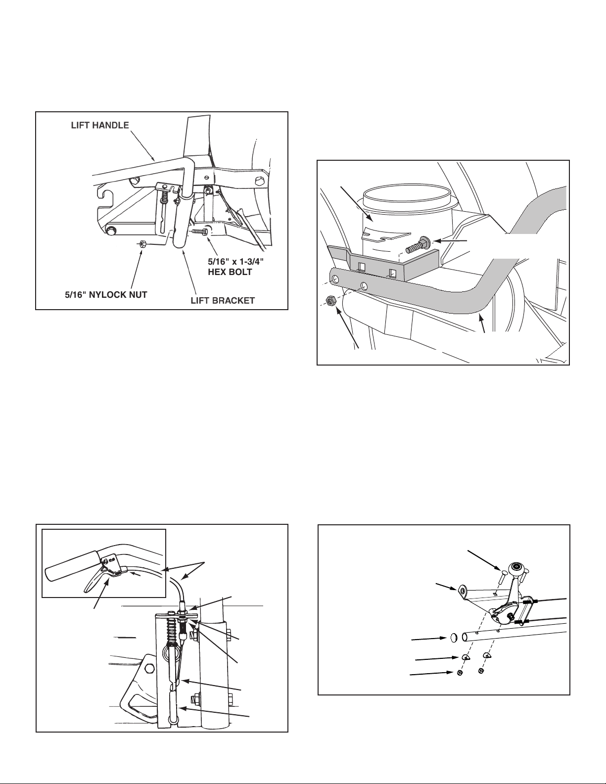
STEP 48: (SEE FIGURE 47)
•Placethelifthandleintotheliftbracketontherightside
ofthesnowthrower.Fastenthehandletothebracket
usingtwo5/16"x1-3/4"hexboltsand5/16"Nylock
nuts.
FIGURE 48 RIGHT SIDE VIEW
NOTE:Besuretheliftreleasecable'splasticcovering
staysinsertedintothetriggerassemblyforthenextstep.
STEP 49: (SEE FIGURE 48)
•Pushthelifthandledownintothelockedposition.
Inserttheendofthecablewireintotheholeinthe
lift rod. Place the threaded tting into the slot in the
liftbracket,withonehexnutaboveandonehexnut
andthelockwasherbelowtheslot.Tightenthenuts,
adjustingthemtoeliminateslackinthecablewire.
ReferalsototheServiceandAdjustmentssectionon
page 27 in this manual.
HINT: Foreasierassemblyoftheliftreleasecable,tiltthe
snow thrower forward onto the spiral auger.
FIGURE 47 RIGHT SIDE VIEW
5/16" NYLOCK NUT
5/16" x 1-3/4"
HEX BOLT
ASSEMBLY OF THE SNOW THROWER
STEP 50: (SEE FIGURE 49)
•Tiltthesnowthrowerbackdowntotheground.
•Removethenylontiewhichfastenstheauger
drivebelttothedischargehousing,leavingthebelt
assembledaroundthepulleys.
•Removethenylontiewhichfastensthechutecrank
rodtothecrankrodsupporttube.
•Assemblethecrankrodsupporttubetothebracketon
the left side of the discharge housing using two 5/16"
x1-1/4"carriagebolts,and5/16"Nylocknuts.
5/16" NYLOCK NUT
5/16" x 1-1/4"
CARRIAGE BOLT
CRANK ROD
SUPPORT TUBE
DISCHARGE
HOUSING
FIGURE 49 LEFT SIDE VIEW
LIFT RELEASE
CABLE
HEX NUT
LOCK
WASHER
HEX NUT
CABLE
WIRE
LIFT
ROD
TRIGGER
ASSEMBLY
FIGURE 50
STEP 51: (SEE FIGURE 50)
•Installtheplugintotheendofthecranksupporttube.
•Attachthechutetiltcontrolassemblytothetopside
ofthecrankrodsupporttubeusingtwo5/16"x1-3/4"
carriagebolts,bowedwashersand5/16"nylocknuts.
CHUTE TILT CONTROL
ASSEMBLY
5/16" x 1-3/4" CARRIAGE BOLT
BOWED WASHER
5/16" NYLOCK NUT
PLUG
Loading ...
Loading ...
Loading ...