Loading ...
Loading ...
Loading ...
16
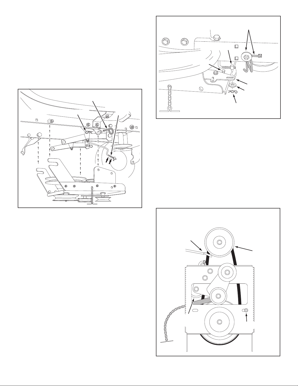
FIGURE 33 RIGHT SIDE VIEW
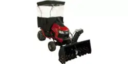
FIGURE 32 RIGHT SIDE VIEW
STEP 33: (SEE FIGURE 33)
•Makesuretheattachmentclutchleveronthedash
panel is in the disengaged (down) position.
•Pivottheupperidlerarmsothatitrestsagainst
thestopboltandispointingtowardthefrontas
shown. Screw the trunnion along the threads of the
engagement rod until it is aligned at the front end of
the idler arm slot. Attach the trunnion to the slot using
the 3/8" thin washer and a 5/64" hairpin cotter.
•Removetheenginepulleykeeperfromthesideof
thetractorframebyremovingthewasherandnut
that secure the keeper. Attach the new pulley keeper
supplied with the snow thrower, reusing the original
bolt,washerandnut.
NOTE:Sometractorsmayalreadybeequippedwitha
pulley keeper that is identical to the new one supplied.
IDLER ARM
5/64" HAIRPIN
COTTER
TRUNNION
STOP BOLT
3/8" THIN
WASHER
NEW ENGINE PULLEY KEEPER WITH
ORIGINAL BOLT, NUT AND WASHER
STEP 34: (SEE FIGURE 34)
•Assembletheshort"V"beltontotheenginepulley
and then onto the large pulley on top of the clutch/idler
assembly.Thebeltmustbeplacedtotheinsideofthe
engine pulley keeper, the idler pulley and the keeper
boltlocatedbesidethelargepulley.
IMPORTANT: Do Notassemblethe"V"beltaroundthe
outsideoftheenginepulleykeeperorthekeeperbolt.
•Go to step 48 on page 21.
FIGURE 34 VIEWED FROM UNDERNEATH
CLUTCH/IDLER ASSEMBLY
STEP 32: (SEE FIGURE 32)
•Besuretoliftupthefrontendoftheengagementrod
as shown when performing the next operation. You
cantemporarilysupporttherodusingarubberband
tied to the engine pulley keeper.
•Attachtheclutch/idlerassemblytothetractorframe
asfollows.Hooktheassembly'snotchedrearpulley
framebracketsontothetwoshoulderboltsyou
assembledtotheinsideofthetractorframe.Liftthe
frontoftheassemblyandattachittotheR.H.andL.H.
hangerbracketsusingtwopivotlockpinsand1/8"
hairpin cotters.
PIVOT LOCK PIN (MM)
(use second hole)
1/8" HAIRPIN COTTER
ENGAGEMENT
ROD
ENGINE
PULLEY
KEEPER BOLT
IDLER
PULLEY
ENGINE
PULLEY
KEEPER
Left Side
of Tractor
Loading ...
Loading ...
Loading ...