
Loading ...
Loading ...
Loading ...
14
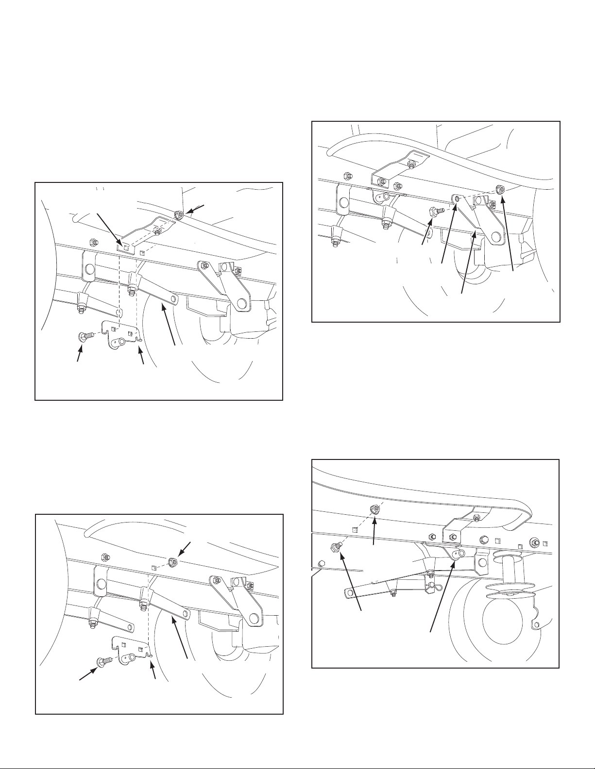
FIGURE 28 RIGHT SIDE VIEW
INSTALLING HANGER BRACKETS
Forbetterclearance,lowerthetractor'ssuspensionarms
using the attachment lift lever.
STEP 26: (SEE FIGURE 25 or 26)
On Tractors With Foot Rest Brackets
• RemovetheboltandnutthatfastentheL.H.andR.H.
footrestbracketstotheframe.
•AttachtheL.H.HangerBracket(marked"L")tothe
inside of the tractor frame using two 3/8" x 1" carriage
boltsand3/8"angednuts.Boltheadsgooninsideof
tractor frame. Repeat for the R.H. side.
FIGURE 26 LEFT SIDE VIEW
FIGURE 25 LEFT SIDE VIEW
On Tractors Without Foot Rest Brackets
•Findtheemptyholebeneaththefootrest.Attachthe
L.H. Hanger Bracket (marked "L") to the inside of
theframeusinga3/8"x1"carriageboltanda3/8"
anged nut. Bolt head goes on inside of tractor frame.
Repeat for the R.H. side.
STEP 28: (SEE FIGURE 28)
•Assembleashoulderboltand3/8"angednuttothe
R.H. side of the tractor frame, using the rst empty
holetotherearoftheR.H.hangerbracket.Boltgoes
on inside of frame.
FIGURE 27 LEFT SIDE VIEW
INSTALLING SHOULDER BOLTS
STEP 27: (SEE FIGURE 27)
•Removethebolt,washerandnutwhichfastenthe
swaybarbrackettotheL.H.sideofthetractorframe.
Replacewithashoulderboltanda3/8"angednut.
Bolt goes on inside of frame.
BOLT REMOVED
FROM THIS HOLE
SWAY BAR
BRACKET
SHOULDER BOLT
3/8"
FLANGED
NUT
3/8" x 1"
CARRIAGE
BOLT
3/8" FLANGED NUT
L.H. HANGER
BRACKET
SUSPENSION ARM
SHOULDER BOLT
3/8"
FLANGED
NUT
R.H. HANGER BRACKET
BOLT REMOVED
FROM THIS HOLE
3/8" x 1"
CARRIAGE
BOLT
3/8" FLANGED
NUT
L.H. HANGER
BRACKET
SUSPENSION ARM
Loading ...
Loading ...
Loading ...