Loading ...
Loading ...
Loading ...
Section 4 - ADJUSTMENTS & REPAIR
4.2.5. MOWER DECK TIMING ROD ADJUSTMENT
The mower deck timing rod is pre-adjusted at
the factory. It is set to maintain the deck in
the same attitude through all heightsof cut. If
suspecting the timing rod requires
adjustment, contact an authorized SNAPPER
dealer for service. See Figure 4.12.
ADJUSTMENT OF THE TIMING
ROD SHOULD ONLY BE DONE
BY AN AUTHORIZ
FIGURE 4.12
4.2.6. CUTTING HEIGHT ADJUSTMENT
The deck cutting height range may be
adjusted to alter the maximum and
minimum cutting deck lift lever.
, k CAUTION
Before attempting any adjustments or repairs, turn
engine "OFF", remove key, remove spark plug wire I
from spark plug and secure wire away from plug.
1. Place the Rear Engine Rider on a smooth,
level surface.
2. Move deck lift lever to the lowest cutting
position.
3. Loosen the two lift quadrant mounting
bolts and eccentric bolt. See Figure 4.13.
SHOWN WiTH COVER REMOVED
4. Rotate eccentric bolt to raise or lower
desired cutting height range.
5. Tighten lift quadrant mounting bolts and
eccentric bolt.
NOTE: Lift quadrant in lowest position gives 1" to 3 1/2"
cutting height range. Lift quadrant in highest position
gives 1-1/2" to 4" cutting height range.
4.3
REAR ENGINE RIDER DRIVE COMPONENTS
The following drive components may be adjusted
by the owner. However, it is recommended that
all adjustments to the Rear Engine Rider be made
by an authorized SNAPPER dealer.
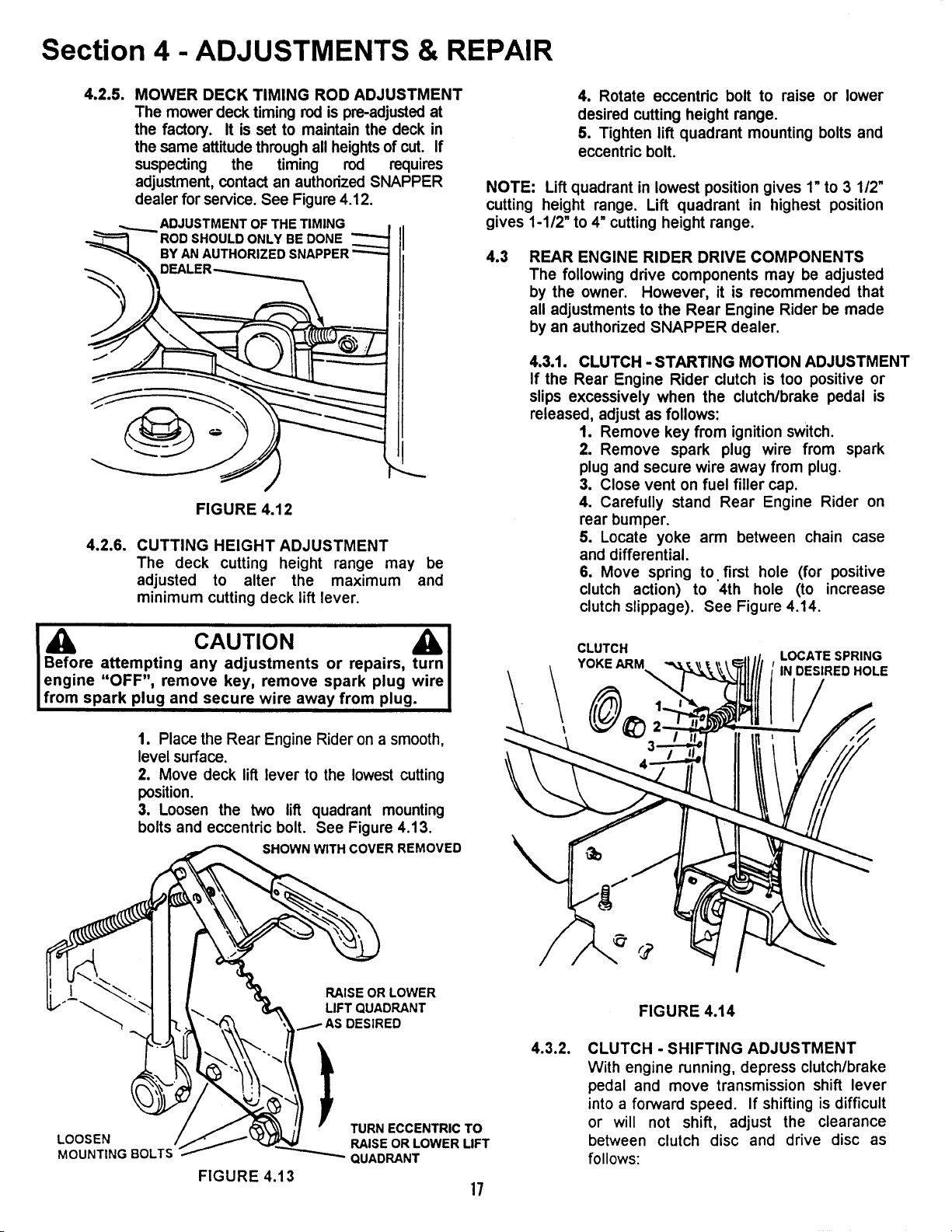
4.3.1. CLUTCH - STARTING MOTION ADJUSTMENT
If the Rear Engine Rider clutch is too positive or
slips excessively when the clutch/brake pedal is
released, adjust as follows:
1. Remove key from ignition switch.
2. Remove spark plug wire from spark
plug and secure wire away from plug.
3. Close vent on fuel filler cap.
4. Carefully stand Rear Engine Rider on
rear bumper.
5. Locate yoke arm between chain case
and differential.
6. Move spring to first hole (for positive
clutch action) to 4th hole (to increase
clutch slippage). See Figure 4.14.
CLUTCH
LOCATE SPRING
YOKE ARM IN DESIRED HOLE
LOOSEN
MOUNTING BOLTS
FIGURE 4.13
RAISE OR LOWER
LIFT QUADRANT
AS DESIRED
TURN ECCENTRIC TO
RAISE OR LOWER LIFT
QUADRANT
17
4.3.2.
FIGURE 4.14
CLUTCH - SHIFTING ADJUSTMENT
With engine running, depress clutch/brake
pedal and move transmission shift lever
into a forward speed. If shifting is difficult
or will not shift, adjust the clearance
between clutch disc and drive disc as
follows:
Loading ...
Loading ...
Loading ...