Loading ...
Loading ...
Loading ...
Section 4 - ADJUSTMENTS & REPAIR
CAUTION
Before attempting any adjustments or repairs, stop
the engine, remove the key, remove the spark plug
wire from the spark plug, and secure spark plug
wire away from spark plug.
1. Follow procedures for standing Rear
Engine Rider on rear bumper. Refer to
Section 3.2.2.
2. Depress clutch/brake pedal all the way
down. Move and hold the park brake lever
in the "ON" position, then release
clutch/brake pedal to lock the park brake.
See Figure 4.17.
3. Move the transmission shift lever to
reverse.
4. Visually inspect to make certain there is
clearance between clutch disc and drive
disc. See Figure 4.15.
CLEARANCE _II=
CLUTCH _....-_"
DISC
DRIVE
DISC
FIGURE 4.15
5. If no clearance is visible, release park
brake by depressing clutch/brake pedal to
release park brake lever.
6. Pull clutch/brake pedal towards
operator's seat and slide one additional
ferrule toward end of cable through the eye
in the clutch/brake pedal arm. See Figure
4.16.
CLUTCH/BRAKE
PEDAL_
CLUTCH/BRAKE
PEDAL ARM
7. Engage park brake as described in Step 2.
8. Check for clearance between dutch disc
and driven disc. If no clearance is visible,
repeat steps 5 and 6 until clearance is visible.
Refer to Figures 4.15 and 4.16.
NOT.___E:If adjustment cannot be completed or made
because all ferrules have been used, contact an
authorized SNAPPER dealer for service.
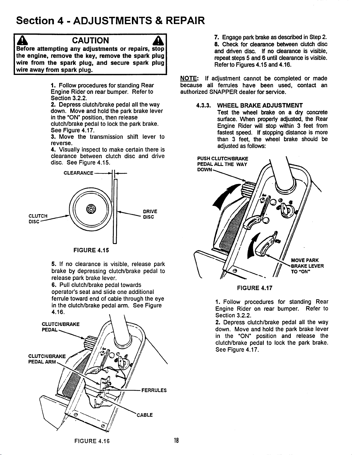
4.3.3. WHEEL BRAKE ADJUSTMENT
Test the wheel brake on a dry concrete
surface. When properly adjusted, the Rear
Engine Rider will stop within 3 feet from
fastest speed. If stopping distance is more
than 3 feet, the wheel brake should be
adjusted as follows:
PUSH CLUTCH/BRAKE
PEDAL ALL THE WAY
MOVE PARK
TO "ON"
FIGURE 4.17
1. Follow procedures for standing Rear
Engine Rider on rear bumper. Refer to
Section 3.2.2.
2. Depress clutch/brake pedal all the way
down. Move and hold the park brake lever
in the "ON" position and release the
clutch/brake pedal to lock the park brake.
See Figure 4.17.
FERRULES
FIGURE 4.16 18
Loading ...
Loading ...
Loading ...