Loading ...
Loading ...
Loading ...
8
ASSEMBLY INSTRUCTIONS
Hardware Used
FF
GG
HH
7
8-1
TT
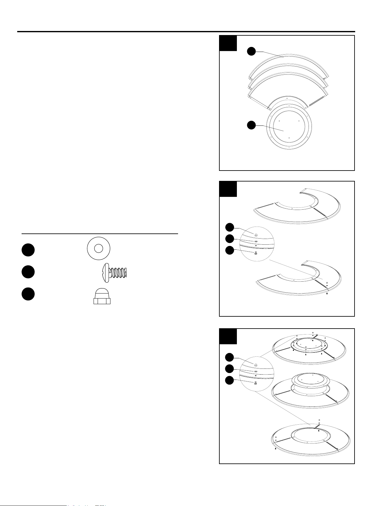
7. WARNING:Remove protective cover before
assembling.
Note: If necessary for proper alignment of reflector
sections, loosen each bolt prior to further assembly
and retighten after sections are aligned.
8. 8-1.Slide two reflector panels together.
Insert one screw M6 X 10 (GG). Slide one washer
Φ 6 (FF) over threaded end of screw M6 X 10 and
screw on cap nut (HH) loosely.
8-2. Slide reflector plate onto reflector panels.
Insert one screw M6 X 10 (GG). Slide one washer
Φ 6 over threaded end of screw M6 X 10 and screw
on cap nut (HH) loosely. Repeat procedure to
complete the assembly of all four sections. Fully
tighten all of the screws in the rolled edge.
x 9
x 9
x 9
Washer Φ 6
Screw M6 X 10
B
HH
FF
GG
A
Cap nuts
8-2
TT
HH
FF
GG
Loading ...
Loading ...
Loading ...