Loading ...
Loading ...
Loading ...
SQUARING THE BLADE TO THE MITER TABLE
See Figures 31 - 33.
• Unplug your saw.
• Pull the saw arm all the way down and engage the lock
pin to hold the saw arm in transport position.
• Loosen the miter lock handle.
• Rotate the miter table until the pointer is positioned
at 0.
• Securely tighten the miter lock handle.
• Loosen bevel lock knob and set saw arm at 0 bevel
(blade set 90°to miter table). Tighten bevel lock knob.
• Place a combination square against the miter table and
the flat part of the blade.
NOTE: Make sure that the square contacts the flat part
of the blade, not the blade teeth.
• Rotate the blade by hand and check the blade-to-table
alignment at several points.
• The edge of the square and the blade should be paral-
lel.
• If the top or bottom of the blade angles away from the
square as shown in figures 32 and 34, adjustments are
needed.
• Using a 13 mm wrench or adjustable wrench, loosen
the lock nut securing positive stop adjustment screw.
Also loosen bevel lock knob.
• Adjust positive stop adjustment screw to bring blade
into alignment with the square.
• Retighten bevel lock knob. Next, retighten lock nut
securing the positive stop adjustment screw. Recheck
blade-to-table alignment.
NOTE: The above procedure can be used to check
blade squareness of the blade to the miter table at
both 0°and 45 angles.
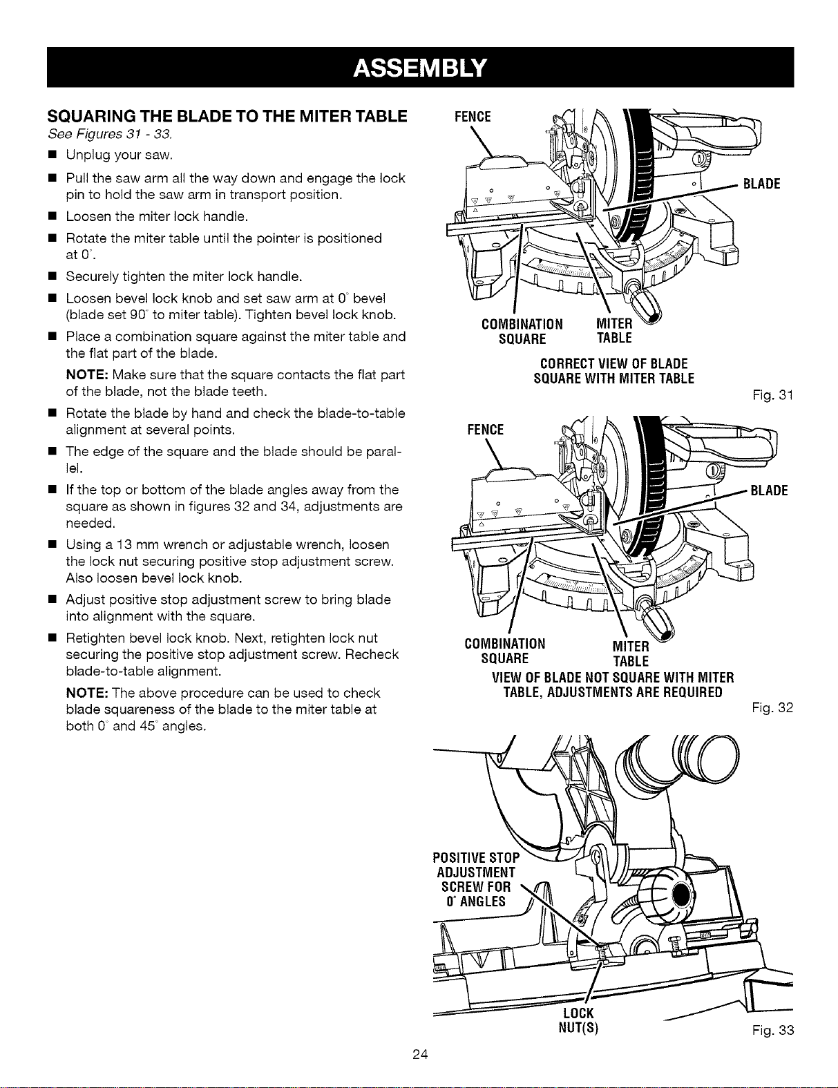
FENCE
COMBINATION MITER
SQUARE TABLE
CORRECTVIEW OFBLADE
SQUAREWITH MITERTABLE
FENCE
COMBINATION MITER
SQUARE TABLE
VIEW OFBLADENOTSQUAREWITH MITER
TABLE,ADJUSTMENTSAREREQUIRED
BLADE
Fig. 31
Fig. 32
POSITIVESTOP
ADJUSTMENT
SCREWFOR
0°ANGLES
24
LOCK
NUT(S)
Fig. 33
Loading ...
Loading ...
Loading ...