Loading ...
Loading ...
Loading ...
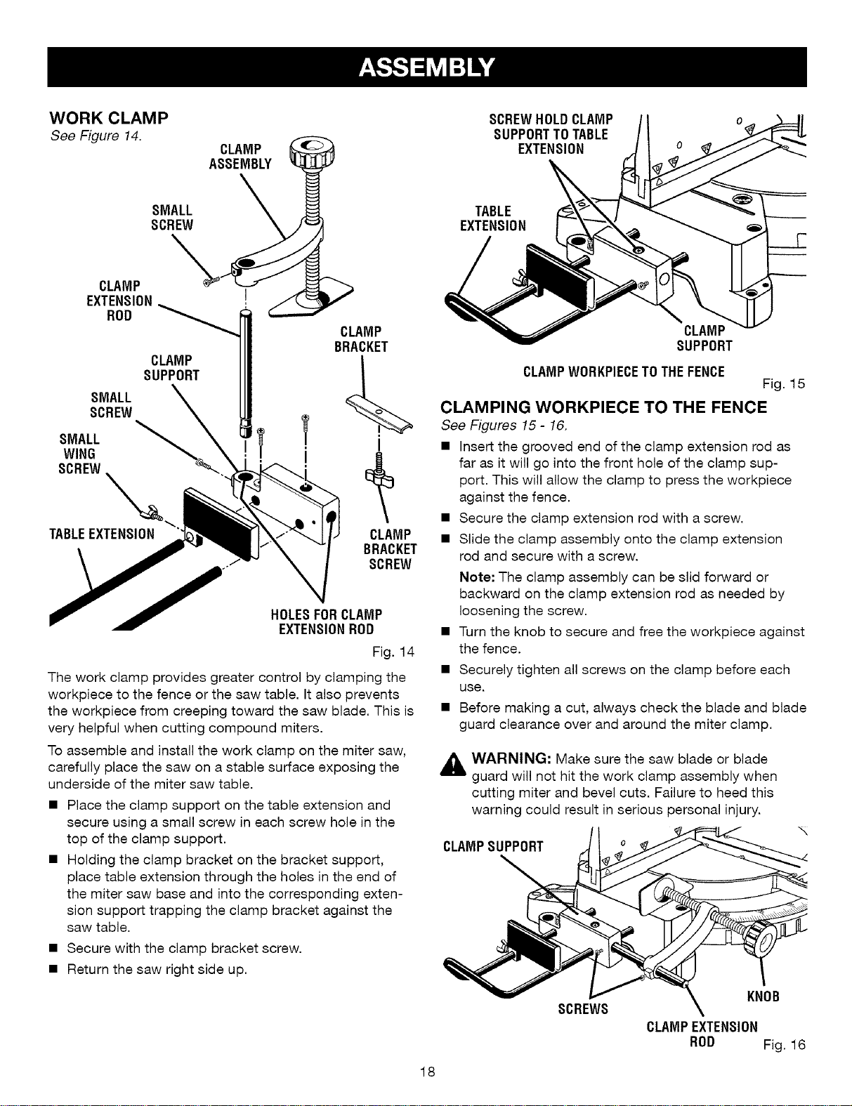
WORK CLAMP
See Figure 14.
SMALL
SCREW
\
CLAMP
EXTENSION
ROD
CLAMP
SUPPORT
SMALL
SCREW
SMALL
WING
SCREW
TABLEEXTENSION
CLAMP
ASSEMBLY
\
CLAMP
BRACKET
CLAMP
BRACKET
SCREW
HOLESFORCLAMP
EXTENSIONROD
Fig. 14
The work clamp provides greater control by clamping the
workpiece to the fence or the saw table. It also prevents
the workpiece from creeping toward the saw blade. This is
very helpful when cutting compound miters.
To assemble and install the work clamp on the miter saw,
carefully place the saw on a stable surface exposing the
underside of the miter saw table.
• Place the clamp support on the table extension and
secure using a small screw in each screw hole in the
top of the clamp support.
• Holding the clamp bracket on the bracket support,
place table extension through the holes in the end of
the miter saw base and into the corresponding exten-
sion support trapping the clamp bracket against the
saw table.
• Secure with the clamp bracket screw.
• Return the saw right side up.
SCREWHOLDCLAMP
SUPPORTTOTABLE
EXTENSION
TABLE
EXTENSION
CLAMP
SUPPORT
CLAMPWORKPIECETOTHEFENCE
Fig. 15
CLAMPING WORKPIECE TO THE FENCE
See Figures 15- 16.
• Insert the grooved end of the clamp extension rod as
far as it will go into the front hole of the clamp sup-
port. This will allow the clamp to press the workpiece
against the fence.
• Secure the clamp extension rod with a screw.
• Slide the clamp assembly onto the clamp extension
rod and secure with a screw.
Note: The clamp assembly can be slid forward or
backward on the clamp extension rod as needed by
loosening the screw.
• Turn the knob to secure and free the workpiece against
the fence.
• Securely tighten all screws on the clamp before each
use.
• Before making a cut, always check the blade and blade
guard clearance over and around the miter clamp.
_i WARNING: Make sure the saw blade or blade
guard will not hit the work clamp assembly when
cutting miter and bevel cuts. Failure to heed this
warning could result in serious personal injury.
CLAMPSUPPORT
18
KNOB
SCREWS
CLAMPEXTENSION
ROD Fig. 16
Loading ...
Loading ...
Loading ...