Operator's Manual
I:RRFI'$1 1RN
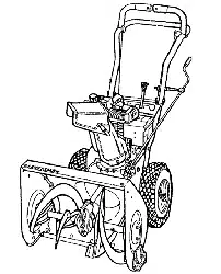
Electric Start
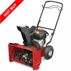
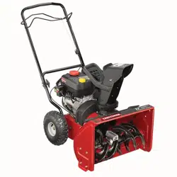
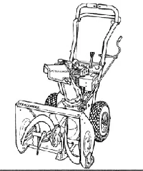
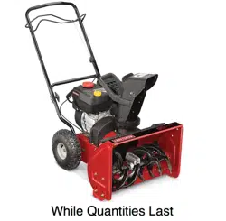
22=INCH SNOW THROWER
Model No. 247.88755
CAUTION: Before using
this product, read this
manual and follow all
safety rules and operating
instructions.
o SAFETY
ASSEMBLY
OPERATION
MAINTENANCE
PARTS LIST
ESPANOL
Sears, Roebuck and Co., Hoffman Estates, IL 60179, U.S.A.
Visit our website: www.sears.com/craftsman FORMNO.769-04055A
2/6/2009
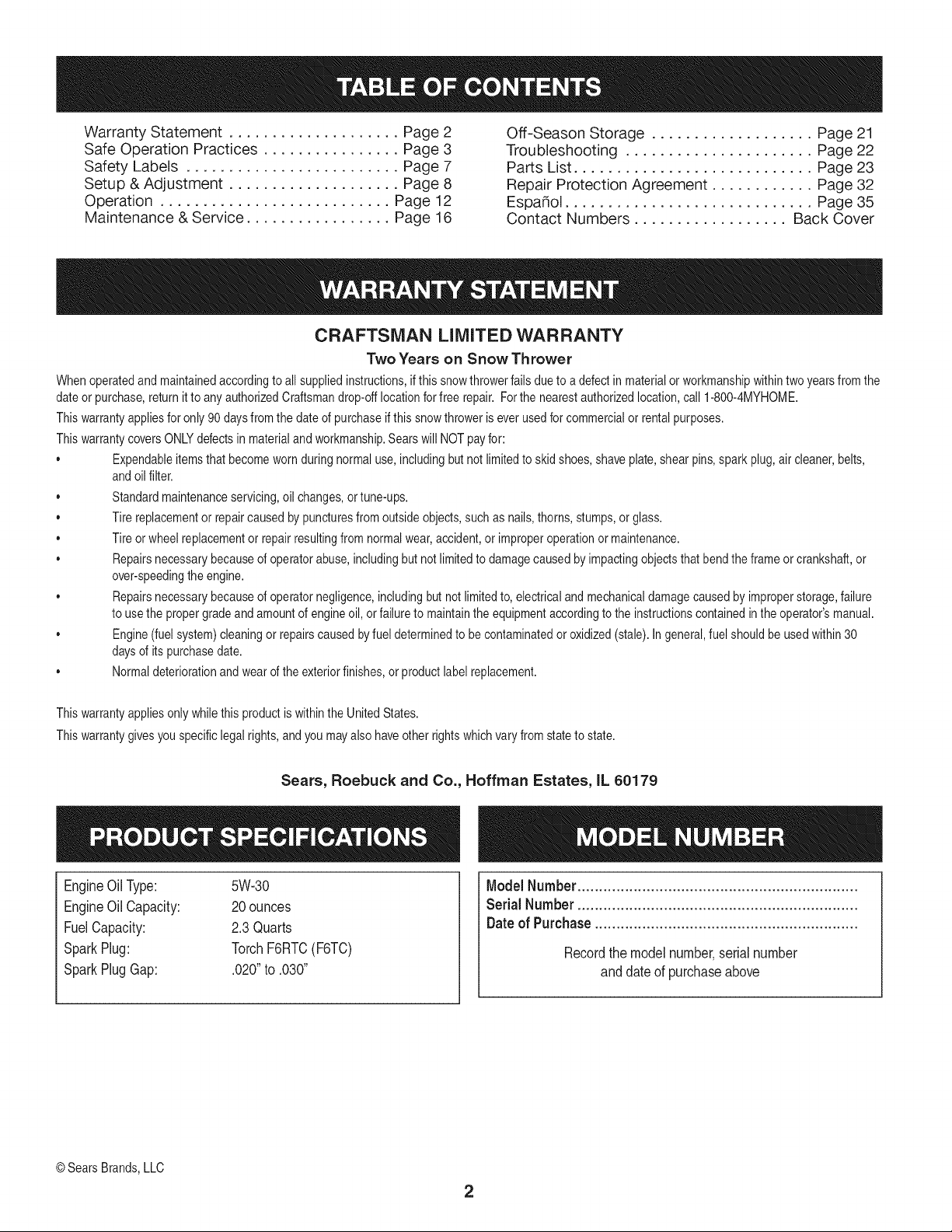
WarrantyStatement.................... Page2
SafeOperationPractices................ Page3
SafetyLabels......................... Page7
Setup&Adjustment.................... Page8
Operation........................... Page12
Maintenance&Service................. Page16
Off-SeasonStorage................... Page21
Troubleshooting...................... Page22
PartsList............................ Page23
RepairProtectionAgreement............ Page32
Espa_ol............................. Page35
ContactNumbers.................. BackCover
CRAFTSMAN LiMiTED WARRANTY
Two Years on Snow Thrower
Whenoperatedand maintainedaccordingto all suppliedinstructions,ifthis snowthrowerfailsdueto a defectin materialorworkmanshipwithintwoyearsfrom the
dateor purchase,return it to anyauthorizedCraftsmandrop-offlocationforfree repair. Forthe nearestauthorizedlocation,call 1-800-4MYHOME.
Thiswarrantyappliesfor only90 daysfromthe dateof purchaseif this snowthroweris ever usedfor commercialor rentalpurposes.
ThiswarrantycoversONLYdefectsin materialandworkmanship.Searswill NOTpayfor:
• Expendableitemsthat becomewornduringnormaluse, includingbut not limitedto skidshoes,shaveplate,shear pins,sparkplug,air cleaner,belts,
andoilfilter.
• Standardmaintenanceservicing,oil changes,or tune-ups.
• Tire replacementor repaircausedbypuncturesfrom outsideobjects,suchas nails,thorns,stumps,orglass.
• Tire or wheel replacementor repairresultingfrom normalwear,accident,or improperoperationor maintenance.
• Repairsnecessarybecauseof operatorabuse,includingbut notlimitedto damagecaused byimpactingobjectsthat bendtheframeor crankshaft,or
over-speedingtheengine.
• Repairsnecessarybecauseof operatornegligence,includingbutnotlimitedto, electricalandmechanicaldamagecausedby improperstorage,failure
to usethe propergradeand amountof engineoil,or failureto maintaintheequipmentaccordingto the instructionscontainedin the operator'smanual.
• Engine(fuelsystem)cleaningor repairscausedbyfuel determinedto be contaminatedor oxidized(stale).In general,fuel shouldbe usedwithin30
daysof its purchasedate.
• Normaldeteriorationandwearof the exteriorfinishes,or productlabelreplacement.
Thiswarrantyappliesonly whilethis productis withinthe UnitedStates.
Thiswarrantygivesyou specificlegalrights,and you mayalso haveotherrightswhichvary from stateto state.
Sears, Roebuck and Co., Hoffman Estates, IL 60179
EngineOilType: 5W-30
EngineOilCapacity: 20ounces
FuelCapacity: 2.3Quarts
SparkPlug: TorchF6RTC(F6TC)
SparkPlugGap: .020"to .030"
ModelNumber.................................................................
Serial Number .................................................................
Dateof Purchase.............................................................
Recordthe modelnumber,serialnumber
anddateof purchaseabove
© Sears Brands,LLC
2
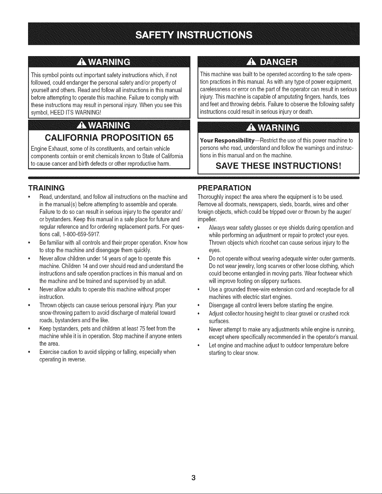
Thissymbolpointsout importantsafetyinstructionswhich,if not
followed,couldendangerthepersonalsafetyand/orpropertyof
yourselfandothers. Readandfollowall instructionsin thismanual
beforeattemptingto operatethismachine.Failureto complywith
theseinstructionsmay resultin personalinjury.Whenyou seethis
symbol,HEEDITSWARNING!
CALIFORNIA PROPOSITION 65
EngineExhaust,someof itsconstituents,and certainvehicle
componentscontainoremitchemicalsknownto Stateof California
to cause cancerand birthdefectsorotherreproductiveharm,
Thismachinewasbuiltto be operatedaccordingto the safeopera-
tion practicesin this manual.As withanytypeof powerequipment,
carelessnessor error on the partof the operatorcan resultin serious
injury.Thismachineis capableof amputatingfingers,hands,toes
andfeetandthrowingdebris.Failureto observethe followingsafety
instructionscouldresultin seriousinjuryor death.
Your Responsibility--Restrict the useof this powermachineto
personswho read,understandandfollowthewarningsand instruc-
tionsin thismanualandon the machine,
SAVE THESE INSTRUCTIONS!
TRAiNiNG
• Read,understand,andfollowall instructionson the machineand
in themanual(s)beforeattemptingto assembleandoperate.
Failureto do socan resultinserious injuryto the operatorand/
orbystanders.Keepthismanualin a safeplaceforfutureand
regularreferenceandfor orderingreplacementparts. Forques-
tionscall,1-800-659-5917.
• Befamiliarwith all controlsandtheir properoperation.Knowhow
to stop the machineand disengagethemquickly.
• Neverallowchildrenunder14yearsof ageto operatethis
machine.Children14andover shouldreadand understandthe
instructionsand safe operationpracticesin thismanualandon
the machineandbe trainedandsupervisedby an adult.
• Neverallowadultsto operatethis machinewithoutproper
instruction.
• Thrownobjectscan causeseriouspersonalinjury.Planyour
snow-throwingpatternto avoiddischargeof materialtoward
roads,bystandersandthe like.
• Keepbystanders,petsandchildrenat least75feetfromthe
machinewhile itisinoperation.Stopmachineifanyoneenters
the area.
• Exercisecautionto avoidslippingor falling,especiallywhen
operatingin reverse.
PREPARATION
Thoroughlyinspecttheareawherethe equipmentis to be used.
Removeall doormats,newspapers,sleds,boards,wires and other
foreignobjects,whichcouldbe trippedoverorthrownby the auger/
impeller.
Alwayswear safetyglassesor eyeshieldsduringoperationand
while performingan adjustmentor repairto protectyoureyes.
Thrownobjectswhich ricochetcancauseseriousinjuryto the
eyes.
Donot operatewithoutwearingadequatewinteroutergarments.
Donot wearjewelry,long scarvesor otherlooseclothing,which
could becomeentangledin movingparts.Wearfootwearwhich
will improvefootingonslipperysurfaces.
Usea groundedthree-wireextensioncordand receptaclefor all
machineswith electricstartengines.
Disengageall controlleversbeforestartingthe engine.
Adjustcollectorhousingheightto cleargravelor crushedrock
surfaces.
Neverattemptto makeanyadjustmentswhileengineis running,
exceptwherespecificallyrecommendedinthe operator'smanual.
Letengineand machineadjustto outdoortemperaturebefore
startingto clearsnow.
3
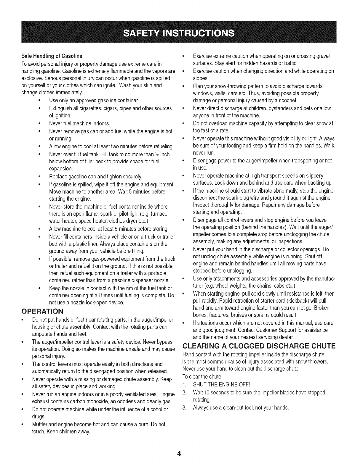
Safe Handling of Gasoline
Toavoidpersonalinjuryor propertydamageuseextremecare in
handlinggasoline.Gasolineis extremelyflammableandthe vaporsare
explosive.Seriouspersonalinjurycan occurwhengasolineis spilled
onyourselfor yourclotheswhichcan ignite.Washyour skinand
changeclothesimmediately.
• Useonly an approvedgasolinecontainer.
• Extinguishall cigarettes,cigars,pipesand other sources
of ignition.
• Neverfuelmachineindoors.
• Neverremovegas capor addfuel whilethe engineis hot
or running.
• Allowengineto coolat leasttwo minutesbeforerefueling.
• Neveroverfill fueltank. Filltankto no morethan1/2inch
belowbottomof filler neckto providespacefor fuel
expansion.
• Replacegasolinecap andtightensecurely.
• If gasolineis spilled,wipeit offthe engineand equipment.
Movemachineto anotherarea.Wait5 minutesbefore
startingthe engine.
• Neverstorethe machineor fuel containerinsidewhere
thereis an open flame,sparkor pilotlight (e.g.furnace,
waterheater,spaceheater,clothesdryer etc.).
• Allowmachineto cool at least5 minutesbeforestoring.
• Neverfill containersinsidea vehicleor ona truckor trailer
bedwitha plasticliner.Alwaysplacecontainersonthe
groundawayfromyourvehicle beforefilling.
• If possible,removegas-poweredequipmentfrom thetruck
ortrailerand refuelit on the ground.If thisis not possible,
then refuelsuchequipmentona trailerwitha portable
container,ratherthan from a gasolinedispensernozzle.
• Keepthe nozzlein contactwith the rimof the fueltankor
containeropeningat all timesuntil fuelingis complete.Do
notuse a nozzlelock-opendevice.
OPERATION
• Do not puthandsorfeetnear rotatingparts,in the auger/impeller
housingor chuteassembly.Contactwiththe rotatingpartscan
amputatehandsandfeet.
• Theauger/impellercontrolleveris a safetydevice.Neverbypass
itsoperation.Doingso makesthe machineunsafeandmay cause
personalinjury.
• Thecontrolleversmustoperateeasilyin bothdirectionsand
automaticallyreturnto the disengagedpositionwhenreleased.
• Neveroperatewitha missingor damagedchuteassembly.Keep
all safetydevicesin placeand working.
• Neverrunan engineindoorsor ina poorlyventilatedarea. Engine
exhaustcontainscarbonmonoxide,anodorlessanddeadlygas.
• Do notoperatemachinewhileunder the influenceof alcoholor
drugs.
• Mufflerandenginebecomehotand can causea burn.Do not
touch.Keepchildrenaway.
• Exerciseextremecautionwhenoperatingon orcrossinggravel
surfaces.Stayalertfor hidden hazardsor traffic.
• Exercisecautionwhenchangingdirectionandwhileoperatingon
slopes.
• Planyoursnow-throwingpatternto avoiddischargetowards
windows,walls,cars etc. Thus,avoidingpossibleproperty
damageor personalinjurycausedby a ricochet.
• Neverdirect dischargeat children,bystandersand petsor allow
anyonein front of the machine.
• Donot overloadmachinecapacityby attemptingto clearsnowat
too fastof a rate.
• Neveroperatethis machinewithoutgoodvisibilityor light. Always
be sureof yourfootingand keepa firm holdon the handles.Walk,
neverrun.
• Disengagepowerto theauger/impellerwhentransportingor not
in use.
• Neveroperatemachineat hightransportspeedson slippery
surfaces.Lookdownand behindand usecare whenbackingup.
• If the machineshouldstart to vibrateabnormally,stopthe engine,
disconnectthe sparkplugwire and groundit againstthe engine.
Inspectthoroughlyfor damage.Repairanydamagebefore
startingand operating.
• Disengageall controlleversandstopenginebeforeyouleave
the operatingposition(behindthe handles).Waituntilthe auger/
impellercomesto a completestopbeforeuncloggingthechute
assembly,makingany adjustments,or inspections.
• Neverput yourhandin the dischargeor collectoropenings.Do
not unclogchuteassemblywhileengineis running.Shutoff
engineand remainbehindhandlesuntilall movingpartshave
stoppedbeforeunclogging.
• Useonly attachmentsand accessoriesapprovedby the manufac-
turer (e.g.wheelweights,tire chains,cabsetc.).
• Whenstartingengine,pullcord slowlyuntilresistanceis felt, then
pull rapidly.Rapidretractionof startercord(kickback)will pull
handandarmtowardenginefasterthan youcan let go. Broken
bones,fractures,bruisesor sprainscould result.
• If situationsoccur whichare notcoveredin this manual,use care
andgoodjudgment.ContactCustomerSupportfor assistance
andthe nameof your nearestservicingdealer.
CLEARING A CLOGGED DISCHARGE CHUTE
Handcontactwiththe rotatingimpellerinsidethe dischargechute
is the mostcommoncauseof injuryassociatedwithsnowthrowers.
Neveruse yourhand to cleanout thedischargechute.
Toclear thechute:
1. SHUTTHEENGINEOFF!
2. Wait 10secondsto be surethe impellerbladeshavestopped
rotating.
3. Alwaysusea clean-outtool,not yourhands.
4
MAINTENANCE & STORAGE
• Nevertamperwithsafetydevices.Checktheirproperoperation
regularly.Referto the maintenanceand adjustmentsectionsof
thismanual.
• Beforecleaning,repairing,or inspectingmachinedisengageall
controlleversandstopthe engine.Waituntilthe auger/impeller
cometo a completestop.Disconnectthe sparkplug wireand
groundagainsttheengineto preventunintendedstarting.
Checkboltsand screwsfor propertightnessat frequentintervals
to keepthe machineinsafeworkingcondition.Also,visually
inspectmachinefor anydamage.
Do notchangetheenginegovernorsettingor over-speedthe
engine.Thegovernorcontrolsthe maximumsafeoperatingspeed
of the engine.
Snowthrowershaveplatesand skidshoesaresubjectto wear
anddamage.Foryoursafetyprotection,frequentlycheckall
componentsand replacewithoriginalequipmentmanufacturer's
(OEM)parts only."Useof parts whichdo not meetthe original
equipmentspecificationsmayleadto improperperformanceand
compromisesafety!"
Checkcontrolleversperiodicallyto verifytheyengageand disen-
gageproperlyand adjust,if necessary.Referto the adjustment
sectioninthis operator'smanualfor instructions.
Maintainor replacesafetyandinstructionlabels,as necessary.
• Observeproperdisposallawsand regulationsfor gas, oil,etc. to
protectthe environment.
Priorto storing,runmachinea few minutestoclear snowfrom
machineand preventfreezeup of auger/impeller.
Neverstorethe machineor fuel containerinsidewherethereisan
openflame,spark or pilot lightsuchas a waterheater,furnace,
clothesdryer etc.
Alwaysreferto the operator'smanualfor properinstructionson
off-seasonstorage.
Checkfuelline,tank, cap,andfittingsfrequentlyfor cracksor
leaks.Replaceif necessary.
Do notcrankenginewithsparkplugremoved.
Accordingto the ConsumerProductsSafetyCommission(CPSC)
andthe U.S.EnvironmentalProtectionAgency(EPA),this product
hasan AverageUsefulLifeof seven(7) years,or 60 hoursof
operation.At the end of theAverageUsefulLifehavethe machine
inspectedannuallybyan authorizedservicedealerto ensurethat
allmechanicalandsafetysystemsareworkingproperlyand not
wornexcessively.Failureto do so can resultin accidents,injuries
ordeath.
DO NOT MODIFY ENGINE
Toavoidseriousinjuryor death,do not modifyengineinany way.
Tamperingwiththe governorsettingcanlead to a runawayengineand
causeit to operateat unsafespeeds.Nevertamperwithfactory setting
of engine governor.
NOTICE REGARDING EMISSIONS
Engineswhich are certifiedtocomplywith Californiaandfederal
EPAemissionregulationsfor SORE(SmallOff RoadEquipment)are
certifiedto operateon regularunleadedgasoline,and mayinclude
the followingemissioncontrolsystems:EngineModification(EM),
OxidizingCatalyst(OC),SecondaryAir Injection(SAI)and ThreeWay
Catalyst(TWO)if so equipped.
SPARK ARRESTOR
Thismachineisequippedwith an internalcombustionengineand
shouldnotbe usedon or nearany unimprovedforest-covered,
brush-coveredor grass-coveredland unlessthe engine'sexhaust
systemisequippedwitha sparkarrestermeetingapplicablelocalor
statelaws (if any)
Ifa sparkattesteris used,it shouldbe maintainedin effectiveworking
orderby theoperator.Inthe State of Californiathe aboveis required
bylaw (Section4442 of the CaliforniaPublicResourcesCode). Other
statesmayhavesimilarlaws. Federallawsapplyonfederallands.
A sparkarresterfor the muffleris availablethroughyournearestSears
PartsandRepairServiceCenter.
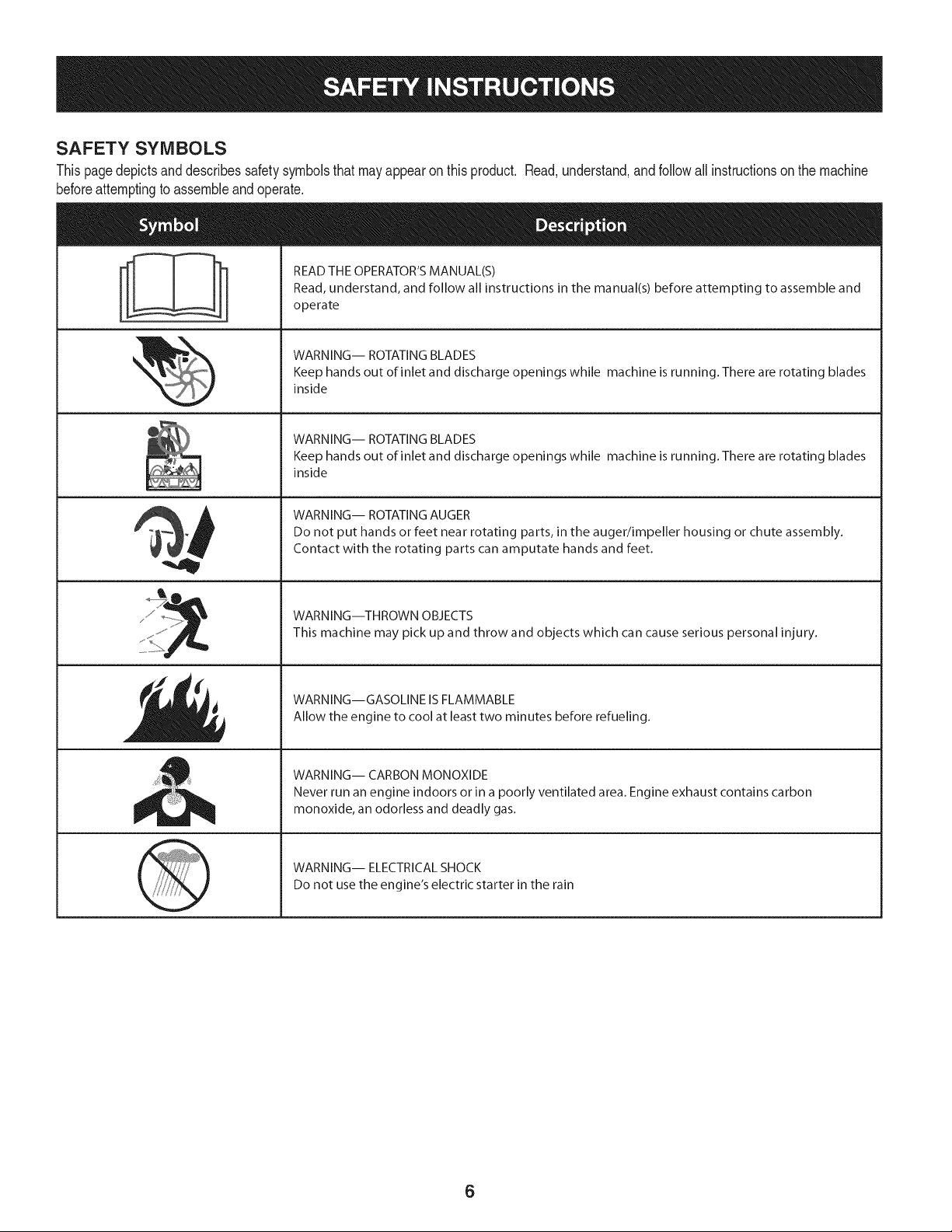
SAFETY SYMBOLS
Thispagedepictsand describessafetysymbolsthatmayappear on this product. Read,understand,andfollowall instructionson the machine
beforeattemptingto assembleandoperate.
i
i
READ THE OPERATOR'S MANUAL(S)
Read, understand, and follow all instructions in the manual(s) before attempting to assemble and
operate
WARNING-- ROTATING BLADES
Keep hands out of inlet and discharge openings while machine is running. There are rotating blades
inside
WARNING-- ROTATING BLADES
Keep hands out of inlet and discharge openings while machine is running. There are rotating blades
inside
WARNING-- ROTATING AUGER
Do not put hands or feet near rotating parts, in the auger/impeller housing or chute assembly.
Contact with the rotating parts can amputate hands and feet.
WARNING--THROWN OBJECTS
This machine may pick up and throw and objects which can cause serious personal injury.
WARNING--GASOLINE IS FLAMMABLE
Allow the engine to cool at least two minutes before refueling.
WARNING-- CARBON MONOXIDE
Never run an engine indoors or in a poorly ventilated area. Engine exhaust contains carbon
monoxide, an odorless and deadly gas.
WARNING-- ELECTRICAL SHOCK
Do not use the engine's electric starter in the rain
6
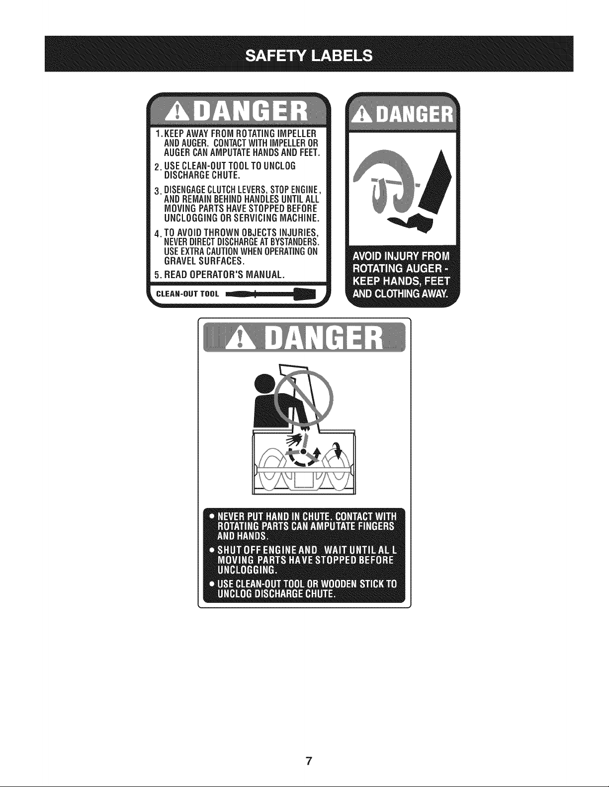
1.KEEPAWAYFROMROTATINGiMPELLER
ANDAUGER,CONTACTWiTHiMPELLEROR
AUGERCANAMPUTATEHANDSANDFEET.
2. USECLEAN-OUTTOOLTOUNCLOG
DISCHARGECHUTE.
3.DISENGAGECLUTCHLEVERS,STOPENGINE,
AND REMAINBEHINDHANDLESUNTILALL
MOVING PARTSHAVE STOPPEDBEFORE
UNCLOGGING OR SERViCiNGMACHINE.
TO AVOIDTHROWN OBJECTSiNJURiES,
NEVERDIRECTDISCHARGEATBYSTANDERS.
USEEXTRACAUTIONWHEN OPERATINGON
GRAVEL SURFACES.
5.BEAD OPERATOR'S MANUAL.
CLEAN-OUT TOOL
7
IMPORTANT:This unitis shippedwith theenginefullof oil. After
assembly,see page 10for fuel andoildetails.
Removing From Carton
1. Cut the cornersof thecartonand lay the sidesflaton the ground.
Removeall packinginserts.
2. Movethe snowthrowerout of thecarton.
3. Makecertainthe carton has beencompletelyemptiedbefore
discardingit.
DO NOTlift the snowthrower bythechute handle.
Before Assembly
NOTE: Referenceto right,left, frontor rearof the unit isfromthe
operatingpositionunlessotherwisestated.
Setting Up The Handle
NOTE: Be awareof the three looselyfitted cabletiesattachedto the
lowerhandlethat will be utilizedlaterto securethe cables.
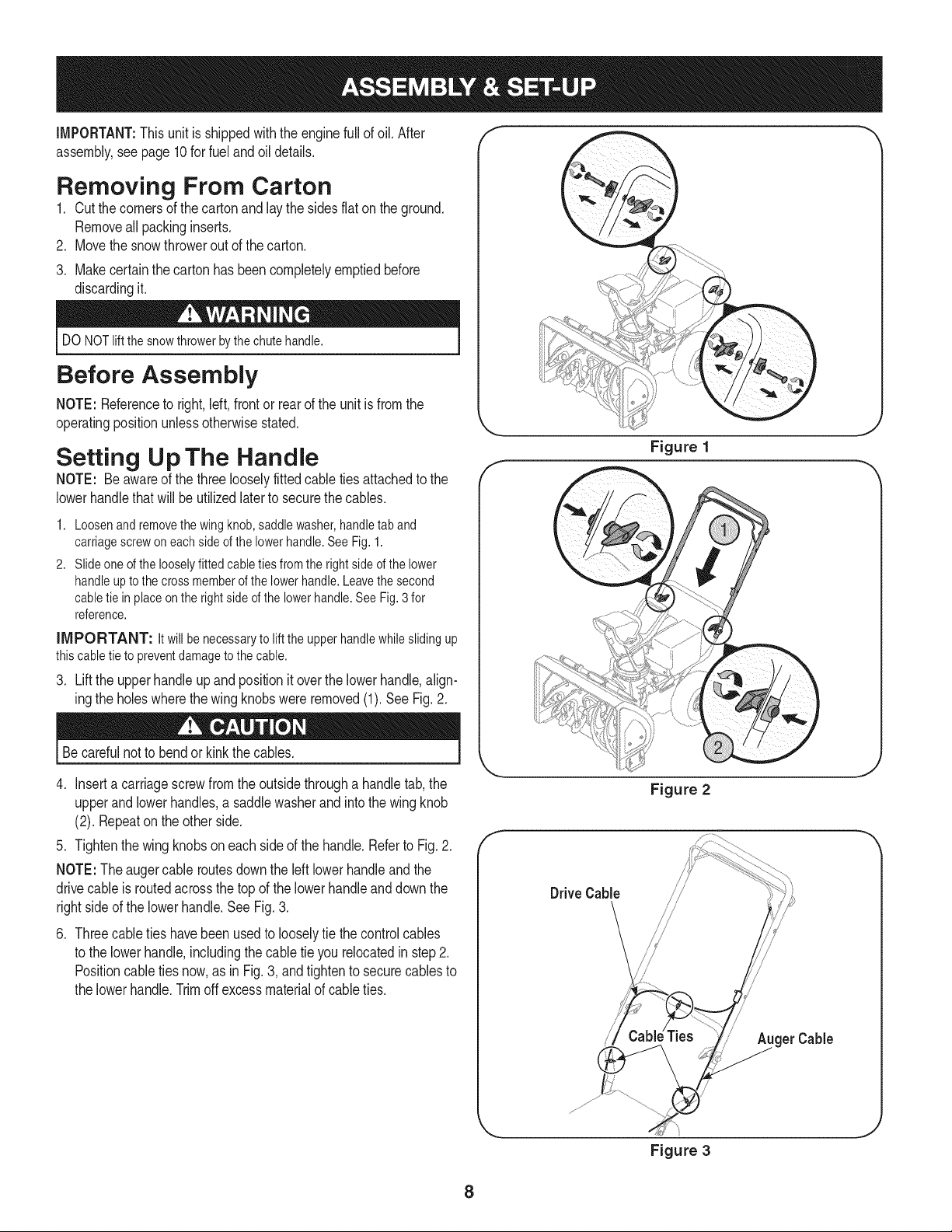
1. Loosenand removethe wing knob,saddlewasher,handletab and
carriagescrew on eachside of the lowerhandle.See Fig.1.
2. Slideone of the looselyfitted cabletiesfromthe right side of the lower
handleup to the cross memberof the lowerhandle.Leavethe second
cabletie in placeon the rightside of the lowerhandle.See Fig.3 for
reference.
iMPORTANT: Itwillbenecessaryto lifttheupperhandlewhileslidingup
thiscabletieto preventdamagetothecable.
3. Lift the upper handleupandpositionit overthelowerhandle,align-
ingthe holeswherethewing knobswereremoved(1).SeeFig.2.
Becarefulnot to bendor kinkthe cables.
4. Inserta carriagescrewfromthe outsidethrougha handletab, the
upperand lowerhandles,a saddlewasherandintothe wing knob
(2). Repeatonthe otherside.
5. Tightenthewing knobson each sideof the handle.Referto Fig. 2.
NOTE:The augercable routesdownthe left lowerhandleand the
drivecableis routedacrossthe top of the lowerhandleanddownthe
rightside of the lowerhandle.See Fig. 3.
.
Threecabletieshavebeenusedto looselytie the controlcables
to the lowerhandle,includingthe cabletie you relocatedinstep 2.
Positioncable tiesnow,as in Fig. 3, and tightento securecablesto
the lowerhandle.Trimoffexcessmaterialof cableties.
f
Figure 1
Figure 2
DriveCable
get Cable
Figure 3
8
Skid Shoe
Thesnowthrowerskidshoesareadjustedupwardatthefactoryforshipping
purposes.Adjustthemdownward,ifdesired,priortooperatingthesnow
thrower.
It is not recommendedthatyouoperatethis snowthrowerongravel
as it can easilypick up andthrowloosegravel,causingpersonal
injuryor damageto the snowthrowerand surroundingproperty.
• Forclosesnowremovalona smoothsurface,raiseskidshoes
higheronthe auger housing.
• Usea middleor lowerpositionwhenthearea to be clearedis
uneven,suchas a graveldriveway
NOTE: If you chooseto operatethe snowthroweron a gravelsurface,
keepthe skid shoesin positionfor maximumclearancebetweenthe
groundandthe shaveplate.
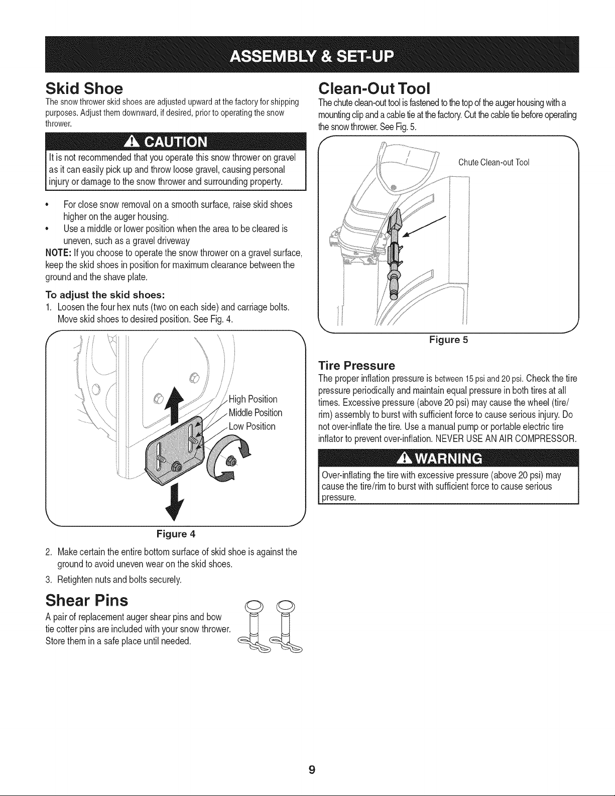
To adjust the skid shoes:
1. Loosenthe fourhex nuts (two on each side)andcarriagebolts.
Moveskidshoesto desiredposition.See Fig.4.
/-
!,/ \
1 i i
/i
h Position
. MiddlePosition
Clean-Out Tool
Thechuteclean-outtoolisfastenedto thetopd theaugerhousingwitha
mountingclipandacabletieat thefactory.Cutthecabletiebeforeoperating
thesnowthrower.SeeFig.5.
ChuteClean-outTool
!
Figure 5
Tire Pressure
The properinflationpressureis between15psiand20psi.Checkthe tire
pressureperiodicallyandmaintainequalpressurein bothtires at all
times.Excessivepressure(above20 psi)may causethe wheel(tire/
rim)assemblyto burst with sufficientforceto causeseriousinjury. Do
notover-inflatethe tire. Use a manualpumpor portableelectrictire
inflatorto preventover-inflation.NEVERUSEANAIRCOMPRESSOR.
Over-inflatingthe tirewithexcessivepressure(above20 psi) may
causethe tire/rimto burstwithsufficientforceto causeserious
pressure.
_J
Figure 4
2. Makecertain theentirebottomsurfaceof skidshoeis againstthe
groundto avoidunevenwearonthe skidshoes.
3. Retightennutsandbolts securely.
Shear Pins
A pairof replacementaugershearpinsand bow
tie cotterpinsare includedwithyoursnowthrower.
Storethem ina safeplaceuntilneeded.
9
Fuel Recommedations
Useautomotivegasoline(unleadedor low leadedto minimizecombus-
tionchamberdeposits)witha minimumof 87 octane.Gasolinewith
upto 10%ethanolor 15%MTBE(MethylTertiaryButyl Ether)canbe
used.Neverusean oil/gasolinemixtureor dirtygasoline.Avoidgetting
dirt,dust,or waterinthefuel tank. DO NOTuse E85gasoline.
• Refuelin awell-ventilatedareawith the engine stopped.Donot
smokeor allowflamesorsparksinthe area wheretheengineis
refueledor wheregasolineisstored.
• Do notoverfillthe fuel tank.Afterrefueling,makesurethe tank
cap is closedproperlyandsecurely.
• Becarefulnot to spillfuel when refueling.Spilledfuelor fuelvapor
mayignite.If any fuel isspilled,makesurethe areaisdry before
startingtheengine.
• Avoidrepeatedor prolongedcontactwithskinor breathingof
vapor.
Adding Fuel
Useextremecarewhenhandlinggasoline.Gasolineis extremely
flammableandthe vaporsareexplosive.Neverfuel the machine
indoorsorwhile the engineishotor running.Extinguishcigarettes,
cigars,pipesandother sourcesof ignition.
Alwayskeephandsandfeetclear of equipmentmovingparts.Do not
usea pressurizedstartingfluid.Vaporsare flammable.
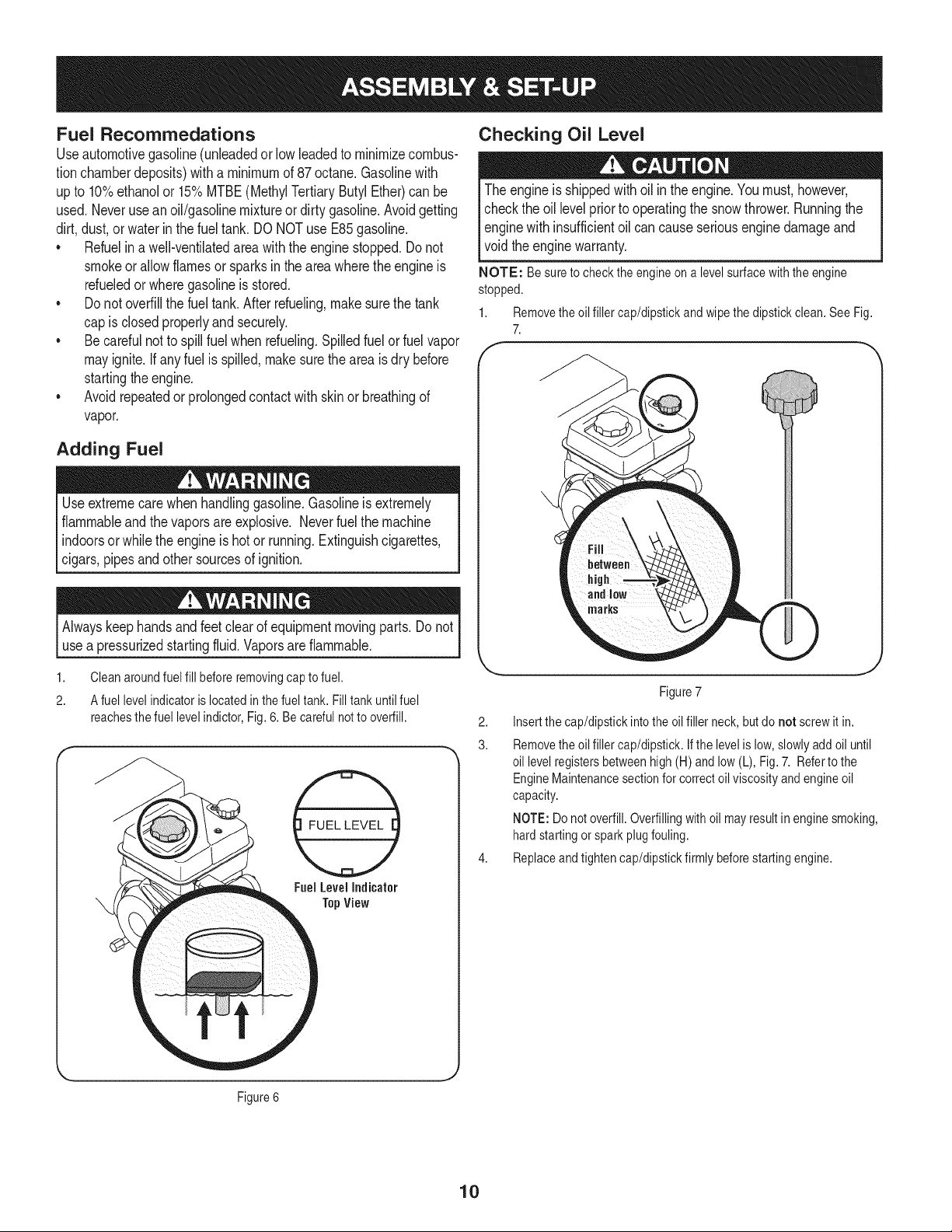
1. Cleanaroundfuel fill beforeremovingcap to fuel.
2. A fuel levelindicator is located inthe fuel tank. Filltank until fuel
reachesthe fuel level indictor,Fig.6. Be careful not to overfill.
FuelLevelIndicator
TopView
Checking Oil Level
The engineis shippedwithoil in theengine.Youmust,however,
checkthe oil levelpriorto operatingthe snowthrower.Runningthe
enginewithinsufficientoil cancauseseriousengine damageand
void theenginewarranty.
NOTE: Besuretochecktheengineonalevelsurfacewiththeengine
stopped.
1. Removetheoilfillercap/dipstickandwipethedipstickclean.SeeFig.
7.
f
Figure7
2. Insertthe cap/dipstickinto the oilfiller neck, butdo not screwit in.
3. Removetheoil filler cap/dipstick. Ifthe levelis low,slowlyadd oil until
oil levelregistersbetweenhigh(H) andlow (L), Fig.7. Referto the
EngineMaintenancesectionfor correctoil viscosityandengine oil
capacity.
NOTE:Do notoverfill.Overfillingwith oil mayresult in enginesmoking,
hardstartingor sparkplug fouling.
4. Replaceandtighten cap/dipstickfirmly beforestartingengine.
Figure6
10
Final Adjustments
IMPORTANT:Checkthe adjustmentsas instructedand makeany
finaladjustmentsnecessarybeforeoperatingthe unit. Checkall nuts
andboltsfortightness.Failureto followtheseinstructionsmaycause
damageto unit.
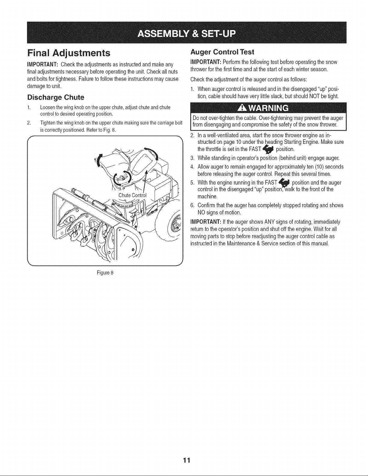
Discharge Chute
1. Loosenthewingknobontheupperchute,adjustchuteandchute
controlto desiredoperatingposition.
2. Tightenthewingknobontheupperchutemakingsurethecarriagebolt
iscorrectlypositioned.Referto Fig.8.
( "
\
Auger Control Test
IMPORTANT:Performthefollowingtest beforeoperatingthesnow
throwerfor the firsttimeandat the startof eachwinterseason.
Checkthe adjustmentof theauger controlas follows:
1. Whenaugercontrolisreleasedand inthe disengaged"up" posi-
tion,cable shouldhavevery little slack, but shouldNOTbetight.
Donot over-tightenthe cable.Over-tighteningmaypreventthe auger
fromdisengagingand compromisethe safetyof the snowthrower.
2. Ina well-ventilatedarea,startthe snow throwerengineas in-
structedon page 10underthe,,.headingStartingEngine.Makesure
the throttleis setin the FAST,_ position.
3. Whilestandingin operator'sposition(behindunit) engageauger.
4. Allowaugerto remainengagedforapproximatelyten (10)seconds
beforereleasingtheauger control.Repeatthisseveraltimes.
5. With the engine runningin the FAST_ positionand theauger
controlinthe disengaged"up"position,w-alk to the front of the
machine.
6. Confirmthatthe augerhascompletelystoppedrotatingand shows
NOsigns of motion.
IMPORTANT:If the augershowsANY signsof rotating,immediately
returnto the operator'spositionand shut off the engine.Waitfor all
movingpartsto stopbeforereadjustingthe augercontrolcableas
instructedinthe Maintenance& Servicesectionof this manual.
Figure8
11
f
j Upper Handle
Drive
Control
StarterRope GasolineCap
\
UpperChute _ Handle
Fuel Cap
ChuteAssembly
Chute Knob
Auger Shave Plate i._.........._...._
Skid Shoe
Clean-outTool
RecoilStarter
Handle
Figure 9
,J
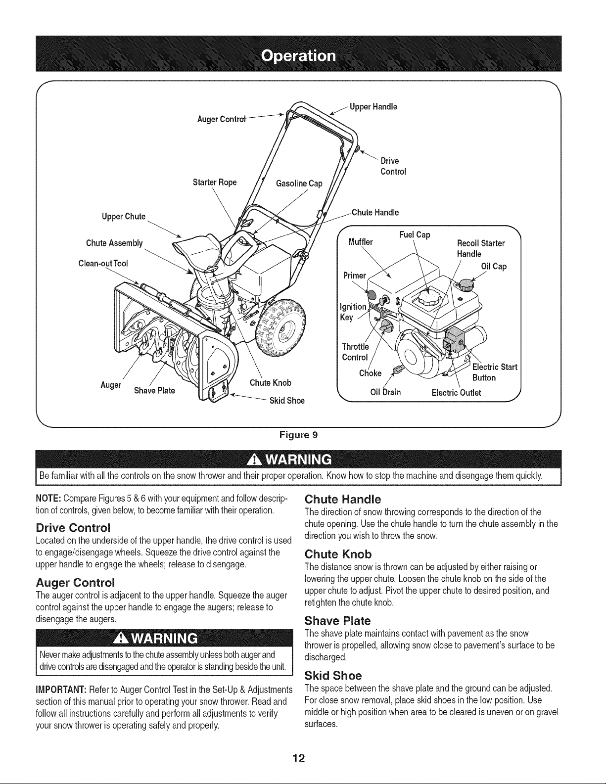
Befamiliarwithall the controlson the snowthrowerand theirproperoperation.Knowhowto stop the machineanddisengagethemquickly.
NOTE:CompareFigures5 &6 withyourequipmentandfollowdescrip-
tionof controls,givenbelow,to becomefamiliarwiththeiroperation.
Drive Control
Locatedon the undersideof the upperhandle,the drivecontrolisused
to engage/disengagewheels.Squeezethe drivecontrolagainstthe
upperhandleto engagethe wheels;releaseto disengage.
Auger Control
Theauger controlis adjacentto the upperhandle.Squeezethe auger
controlagainstthe upperhandleto engagethe augers; releaseto
disengagethe augers.
Nevermakeadjustmentstothechuteassemblyunlessbothaugerand
drivecontrolsaredisengagedandtheoperatorisstandingbesidetheunit.
IMPORTANT:Referto AugerControlTestinthe Set-Up& Adjustments
sectionof this manualpriorto operatingyoursnowthrower.Readand
followall instructionscarefullyand performall adjustmentsto verify
yoursnowthroweris operatingsafelyandproperly.
Chute Handle
The directionof snowthrowingcorrespondsto thedirectionof the
chuteopening.Use thechutehandleto turn thechuteassemblyin the
directionyouwish to throw the snow.
Chute Knob
The distancesnowis throwncan beadjustedby either raisingor
loweringthe upperchute.Loosenthe chute knobonthe side of the
upperchuteto adjust.Pivotthe upper chuteto desiredposition,and
retightenthechute knob.
Shave Plate
The shaveplatemaintainscontact with pavementas the snow
throweris propelled,allowingsnowcloseto pavement'ssurfaceto be
discharged.
Skid Shoe
The spacebetweenthe shaveplateand thegroundcan beadjusted.
Forclose snowremoval,placeskid shoesin the lowposition.Use
middleor highpositionwhenarea to be clearedis unevenor on gravel
surfaces.
12
Augers
Whenengaged,the augersrotateanddrawsnowintothe auger
housing.
Chute Assembly
Snowdrawninto theaugerhousingis dischargedout the chute
assembly.
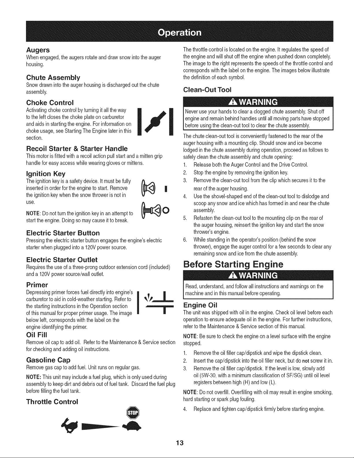
Choke Control
Activatingchokecontrolby turningitall theway
to the left closesthe chokeplateoncarburetor
andaidsin startingthe engine.Forinformationon
chokeusage,see StartingThe Enginelaterin this
section.
Recoil Starter & Starter Handle
Thismotorisfittedwith a recoilactionpullstart and a mittengrip
handlefor easyaccess whilewearingglovesormittens.
Ignition Key
Theignitionkeyisa safetydevice.It mustbe fully _ ,,,,._
insertedinorderfor theengineto start. Remove
Fe
the ignitionkeywhenthe snowthrowerisnot in
use.
NOTE:Do notturn the ignitionkeyin anattemptto
startthe engine.Doingso maycauseit to break.
|
Electric Starter Button
Pressingthe electricstarterbuttonengagesthe engine'selectric
starterwhenpluggedintoa 120Vpowersource.
Electric Starter Outlet
Requiresthe useof a three-prongoutdoorextensioncord(included)
anda 120Vpowersource/walloutlet.
Primer
Depressingprimerforcesfuel directlyintoengine's
carburetorto aidin cold-weatherstarting.Referto qk_P,_.__L__
the startinginstructionsin the Operationsection I
of this manualfor properprimerusage.The image |
belowleft,correspondswiththe labelonthe
engineidentifyingthe primer.
Oil Fill
Removeoilcap to addoil. Referto the Maintenance&Servicesection
for checkingandaddingoil instructions.
Gasoline Cap
Removegascap to add fuel. Unit runson regulargas.
NOTE:This unit may includea fuel plug,whichisonly usedduring
assemblyto keepdirt and debrisout of fueltank. Discardthefuel plug
beforefillingthe fuel tank.
Throttle Control
The throttlecontrolis locatedonthe engine.It regulatesthe speedof
the engineand will shut off the enginewhen pusheddowncompletely.
The imageto the rightrepresentsthe speedsof the throttlecontroland
correspondswith the label on the engine.The imagesbelowillustrate
the ddinition of eachsymbol.
Clean=Out Tool
Neveruseyour handsto clear a cloggedchuteassembly.Shutoff
engineandremainbehindhandlesuntilall movingpartshavestopped
[before usngthe c can-outtoo to c earthechute assemby.
The chuteclean-outtool is convenientlyfastenedto the rearof the
augerhousingwith a mountingclip. Shouldsnowand ice become
lodgedinthe chute assemblyduringoperation,proceedas followsto
safelycleanthe chuteassemblyand chuteopening:
1. Releaseboththe AugerControland the Drive Control.
2. Stoptheengineby removingthe ignitionkey.
3. Removethe clean-outtool from the clipwhichsecuresit to the
rearof the auger housing.
4. Usethe shovel-shapedendof the clean-outtoolto dislodgeand
scoopanysnow and ice whichhas formedinand nearthe chute
assembly.
5. Refastenthe clean-outtoolto the mountingclip on the rearof
the auger housing,reinsertthe ignitionkeyand startthe snow
thrower'sengine.
6. Whilestandingin theoperator'sposition(behindthe snow
thrower),engagethe augercontrolfor a few secondsto clearany
remainingsnowand icefrom the chuteassembly.
Before Starting Engine
Read,understand,and follow all instructionsandwarningsonthe
machineandinthis manualbeforeoperating.
Engine Oil
The unitwas shippedwith oilin the engine.Checkoillevelbeforeeach
operationto ensureadequateoil inthe engine.Forfurtherinstructions,
referto the Maintenance& Servicesectionof this manual.
NOTE:Be sureto checkthe engineon a levelsurfacewiththeengine
stopped.
1. Removethe oil filler cap/dipstickand wipe thedipstickclean.
2. Insertthe cap/dipstickintothe oil filler neck,but do not screwit in.
3. Removethe oil filler cap/dipstick.Ifthe levelis low,slowlyadd
oil (5W-30,with a minimumclassificationof SF/SG)untiloil level
registersbetweenhigh (H) and low (L).
NOTE:Donot overfill.Overfillingwithoil may resultin enginesmoking,
hardstartingor sparkplugfouling.
4. Replaceand tightencap/dipstickfirmly beforestartingengine.
13
Gasoline
Useautomotivegasoline(unleadedor low leadedto minimizecombus-
tionchamberdeposits)witha minimumof 87 octane.Gasolinewith
upto 10%ethanolor 15%MTBE(MethylTertiaryButyl Ether)canbe
used.Neverusean oil/gasolinemixtureor dirtygasoline.Avoidgetting
dirt,dust,or waterinthefuel tank. DO NOTuse E85gasoline.
• Refuelin awell-ventilatedareawith the engine stopped.Donot
smokeor allowflamesorsparksinthe area wheretheengineis
refueledor wheregasolineisstored.
• Do notoverfillthe fuel tank.Afterrefueling,makesurethe tank
cap is closedproperlyandsecurely.
• Becarefulnot to spillfuel when refueling.Spilledfuelor fuelvapor
mayignite.If any fuel isspilled,makesurethe areaisdry before
startingtheengine.
• Avoidrepeatedor prolongedcontactwithskinor breathingof
vapor.
Useextremecarewhenhandlinggasoline.Gasolineis extremely
flammableand the vaporsare explosive.Neverfuelthe machine
indoorsor whilethe engineishot or running.Extinguishcigarettes,
cigars,pipes andother sourcesof ignition.
.
2.
Cleanaroundfuelfill beforeremovingcap to fuel.
Afuel levelindicatorislocatedinthe fuel tank. Filltankuntilfuel
reachesthe fuel levelindictor.See Figure10inset.Becarefulnot
to overfill.
Starting The Engine
Determinethat yourhome'swiringis a three-wiregroundedsystem.
Aska licensedelectricianif you are notcertain.
Ifyou havea groundedthree-prongreceptacle,proceedas follows.
Ifyou do not havethe properhousewiring,DONOTusethe electric
starterunder anyconditions.
1. Plugthe extensioncord intothe outlet locatedon the engine's
surface.Plugthe otherendof extensioncord intoa three-prong
120-volt,grounded,AC outlet in a well-ventilatedarea.
2. Movethrottlecontrolto FAST(rabbit)_ position.
3. Movechoketo the ONpositionI,,i(I (coldenginestart). Ifengine
is warm,placechoke inOFF position.
4. Pushprimerthreeto five (3-5) times,makingsureto covervent
holewhen pushing.If engineis warm,pushprimeronly once.
Alwayscoverventholewhenpushing.Coolweathermayrequire
primingto be repeated.
5. Pushstarterbuttonto startengine.Oncetheenginestarts,im-
mediatelyreleasestarterbutton.Electricstarteris equippedwith
thermaloverloadprotection;systemwill temporarilyshut-downto
allow starterto cool if electricstarterbecomesoverloaded.
6. As the enginewarms,slowlyrotatethechoke controlto OFF
position,ifthe enginefalters, restartengineand runwith choke
at half-chokepositionfor a shortperiod of time,andthenslowly
rotatethe chokeintoOFF position.
7. Afterengineis running,disconnectpowercord fromelectric
starter.Whendisconnecting,alwaysunplugthe end at the wall
outletbeforeunpluggingthe oppositeend fromthe engine.
Recoil Starter
Alwayskeephandsandfeetclear of movingparts.Do notuse a
pressurizedstartingfluid.Vaporsare flammable.
NOTE: Forlocationof allthe enginecontrolsreferredto in this section,
referto Fig. 9 onpage 12.
NOTE:Allowtheengineto warmupfor a few minutesafterstarting.
Theenginewill not developfull poweruntil it reachesoperating
temperatures.
1. Makecertainboththe augercontrolanddrivecontrolare inthe
disengaged(released)position.
2. Insertignitionkeyinto slot. Makesureit snaps intoplace.Donot
attemptto turnthe key.
NOTE:The enginecannotstart withoutthe key fully insertedintothe
ignitionswitch.
Electric Starter
Theoptionalelectricstarterisequippedwitha groundedthree-wire
powercord andplug,and isdesignedto operateon 120voltAC
householdcurrent.It mustbeusedwitha properlygroundedthree-
prongreceptacleat all timesto avoidthe possibilityof electricshock.
Followall instructionscarefullypriorto operatingthe electricstarter.
DO NOTuse electricstarterin the rain.
Donot pull the starterhandlewhiletheengine running.
1. Movethrottlecontrolto FAST(rabbit)_ position.
2. Movechoketo the ONpositionI,,,_1(coldengine start). If engineis
warm,placechokeinOFF position.
3. Pushprimerthreeto five (3-5) times,makingsureto covervent
holewhen pushing.If engineis warm,pushprimeronly once.
Alwayscoverventholewhenpushing.Coolweathermayrequire
primingto be repeated.
4. Pullgentlyonthe starterhandleuntil it beginsto resist,thenpull
quicklyand forcefullyto overcomethe compression.Do not release
the handleand allowit to snapback. ReturnropeSLOWLYto
originalposition.If required,repeatthisstep.
5. As the enginewarms,slowlyrotatethechokecontrolto OFF
position.If the enginefalters,restartengineand runwith chokeat
half-chokepositionfora shortperiodof time,and thenslowlyrotate
the choke intoOFFposition.
Toavoidunsupervisedengineoperation,neverleavethe machine
unattendedwiththe enginerunning.Turnthe engineoff after useand
removeignitionkey.
14
Stopping The Engine
Runenginefor a few minutesbeforestoppingto help dry off any
moistureonthe engine.
1. Movethrottlecontrolto STOP position.
2. Removetheignitionkey.Removingthe keywill reducethe pos-
sibilityof unauthorizedstartingof theenginewhileequipmentis
not in use. Keepthe key in a safeplace.The enginecannotstart
withoutthe ignitionkey.
3. Wipeany moistureawayfromthe controlson theengine.
Before Stopping
1. Runenginefor a few minutesto helpdry off anymoistureon engine.
2. Toavoidpossiblefreeze-upof the recoilstarter,followthisstep:
Recoil Starter
a. Withtheengine running,pullthe starterropewitha rapid,
continuousfull arm strokethreeor fourtimes.
To Stop The Snow Thrower
1. Tostopthe wheels,releasethe drivecontrol.
2. Tostopthrowingsnow,releasethe augercontrol.
3. Tostopengine,pushthrottlecontrolleverto OFF I_ and pullout
the key.Donot turn key.
Thetemperatureof mufflerandthe surroundingareasmay exceed
1500F.Avoidtheseareas.
Clearing The Snow
CAUTION:Checktheareato be clearedfor foreignobjects.Remove
foreignobjects,if any.
1. Start theenginefollowingstartinginstructions.
2. Allowtheengineto warmupfor a few minutesas the enginewill not
developfull poweruntilit reachesoperatingtemperature.
3. Rotatethe chute assemblyto the desireddirection,awayfrom
bystandersand/or buildings.
4. Makingcertainno bystandersor obstaclesare in front d the unit,
squeezethe augercontrolcompletelyagainstthe upper handleto
fullyengagetheaugers.
5. Whiletheaugercontrolisengaged,squeezethe drivecontrol
completelyagainstthe upperhandleto engagethe wheels.Do not
"feather"thedrive control.
6. As the snowthrowerstartsto move,maintaina firmholdon the
handle,and guide the snowthroweralongthe pathto be cleared.
7. Releasethe augerand drivecontrolsto stop the snowthrowing
actionandforwardmotion.
NOTE:Yourunit isequippedwith a clutchin the transmission.If the
wheelsstopturningwhiletryingto dischargelargevolumesof snow,
immediatelydisengagethedrivecontroland allowthe rotatingaugers
to dischargesnowfromthe housing.Reducethe clearingwidthand
continueoperation.
8. On eachsucceedingpass,readjustthe chuteassemblyto the
desiredpositionandslightlyoverlapthe previouslyclearedpath.
15
Positioning Discharge Chute
Loosenthechuteknobandpivotupperchuteto desiredposition.Tighten
the chuteknobmakingsurethe carriageboltiscorrectlypositioned.
Rotatechutehandleto desiredoperatingposition.
Donot lift the snowthrowerat any time bythe chute handle.
Operating Tips
1. Formostdficientsnowremoval,removesnowimmediatelyafteritfalls.
2. Dischargesnowdownwindwheneverpossible.Slightlyoverlap
each previouspath.
3. Setthe skid shoes 1/4"belowthe shaveplatefor normalusage.
The skid shoesmay be adjustedupwardfor hard-packedsnow.
NOTE:It isnot recommendedthatyouoperatethis snowthroweron
gravelas loosegravelcan be easilypickedupand thrownbythe auger
causingpersonalinjuryand/or damageto the snowthrower.
4. Iffor somereason,you haveto operatethe snowthrowerongravel,
keepthe skidshoe inthe highestpositionfor maximumclearance
betweenthe groundandthe shaveplate.
5. Cleanthe snowthrowerthoroughlyaftereachuse.
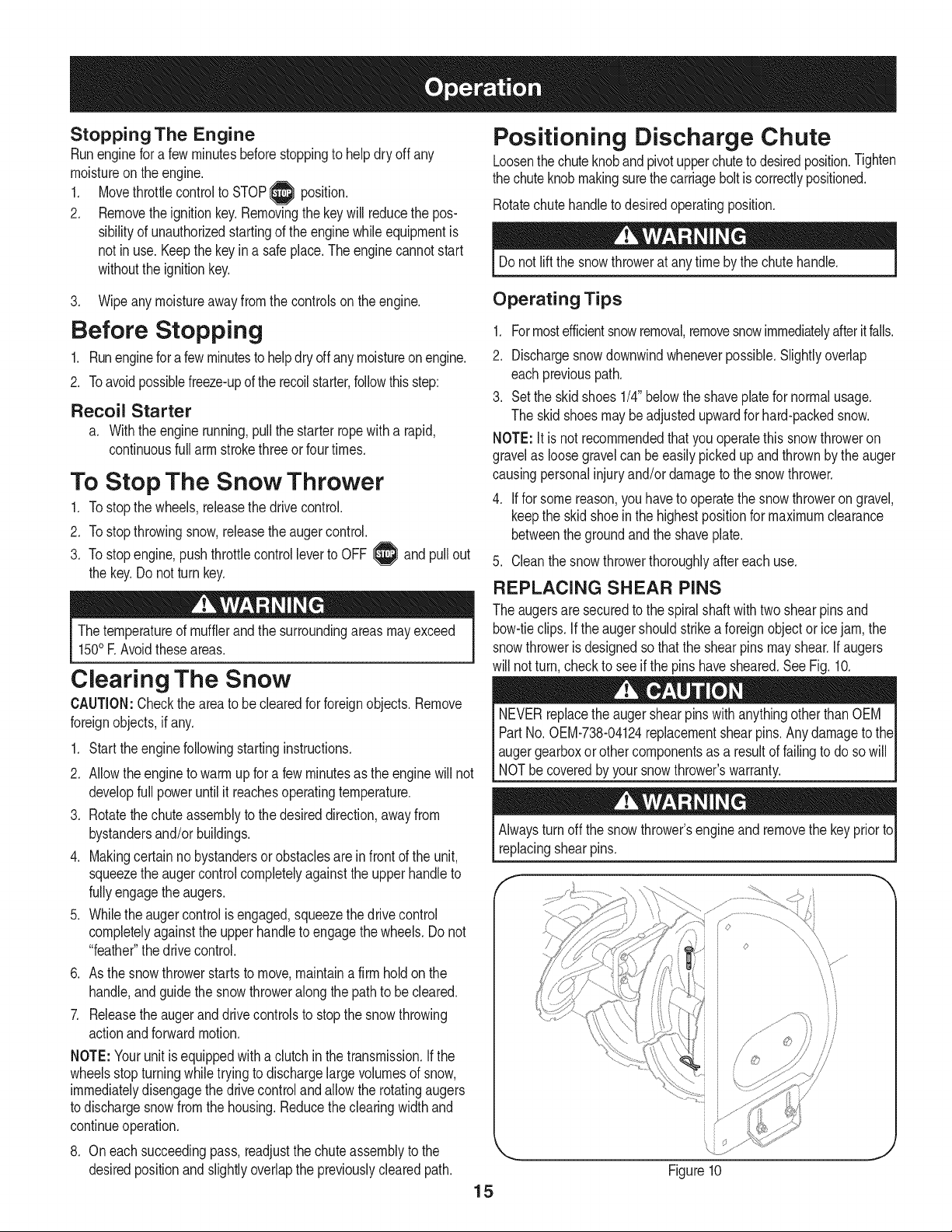
REPLACING SHEAR PINS
The augersare securedto the spiralshaftwithtwo shearpinsand
bow-tieclips. Ifthe augershouldstrikea foreignobjector icejam,the
snowthroweris designedso thatthe shearpins mayshear.If augers
will not turn,checkto seeif the pinshavesheared.SeeFig. 10.
NEVERreplacethe augershearpinswithanythingotherthan OEM I
PartNo. 0EM-738-04124replacementshearpins.Anydamageto theI
augergearboxor othercomponentsas,a resultof failingto do sowill I
NOTbecoveredbyyour snowthrowers warranty.
Alwaysturn offthe snowthrower'sengineand removethe keyprior to
replacingshearpins.
f- _,,
\\
Figure10
J
ENGINE MAINTENANCE
Beforelubricating,repairing,or inspecting,disengageall controls
Iand stop engine.Waituntilall movingpartshavecometo a complete
[stop.
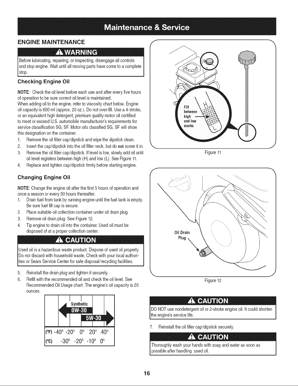
Checking Engine Oil
NOTE: Checktheoil levelbeforeeachuseandafter every five hours
of operationto besurecorrectoil levelismaintained.
Whenaddingoil to the engine,referto viscositychart below.Engine
oilcapacityis 600ml (approx.20 oz.). Donot over-fill.Usea 4-stroke,
oran equivalenthighdetergent,premiumquality motoroil certified
to meet or exceedU.S.automobilemanufacturer'srequirementsfor
serviceclassificationSG, SE MotoroilsclassifiedSG, SFwill show
thisdesignationonthe container.
1. Removethe oil fillercap/dipstickand wipethe dipstickclean.
2. Insertthe cap/dipstickintothe oil filler neck,butdo not screwitin.
3. Removethe oil fillercap/dipstick.Iflevelislow, slowlyadd oiluntil
oil levelregistersbetweenhigh (H) and low (L). See Figure11.
4. Replaceandtightencap/dipstickfirmlybeforestartingengine.
Changing Engine Oil
NOTE:Changethe engineoil after the first5 hoursof operationand
oncea seasonorevery50 hoursthereafter.
1. Drainfuelfromtank by runningengineuntilthe fuel tank isempty.
Besurefuel fill cap is secure.
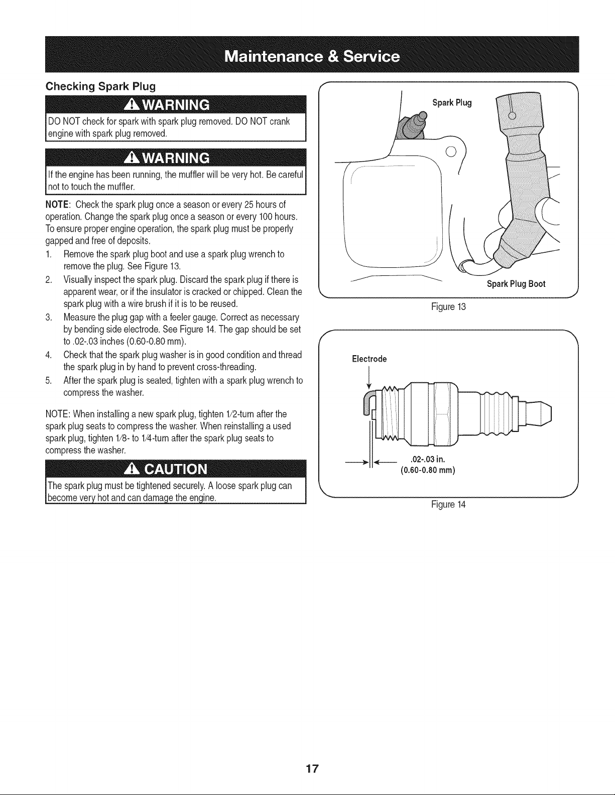
2. Placesuitableoil collectioncontainerunderoildrain plug.
3. Removeoil drainplug.See Figure12.
4. Tipengine to drainoil intothe container.Usedoil mustbe
disposedof at apropercollectioncenter.
tUsedoil isa hazardouswasteproduct.Disposeof used oilproperly.
Do notdiscardwith householdwaste.Checkwith your localauthori-
ies or SearsServiceCenterfor safedisposal/recyclingfacilities.
f
Figure11
J
Oil Drain
Plug
.
6.
Reinstallthe drainplugandtightenit securely.
Refillwiththe recommendedoil andcheckthe oil level. See
RecommendedOilUsage chart. The engine's oil capacity is 20
ounces.
Figure12
J
Synthetic
1
(oF)-40o-20 o 0o 200 400
("c) -30° -20 ° -10° 0°
DONOT usenondetergentoilor 2-strokeengineoil. It couldshorten
the engine'sservicelife.
7. Reinstallthe oil fillercap/dipsticksecurely.
Thoroughlywashyourhandswithsoapandwateras soonas
possibleafterhandling usedoil.
16
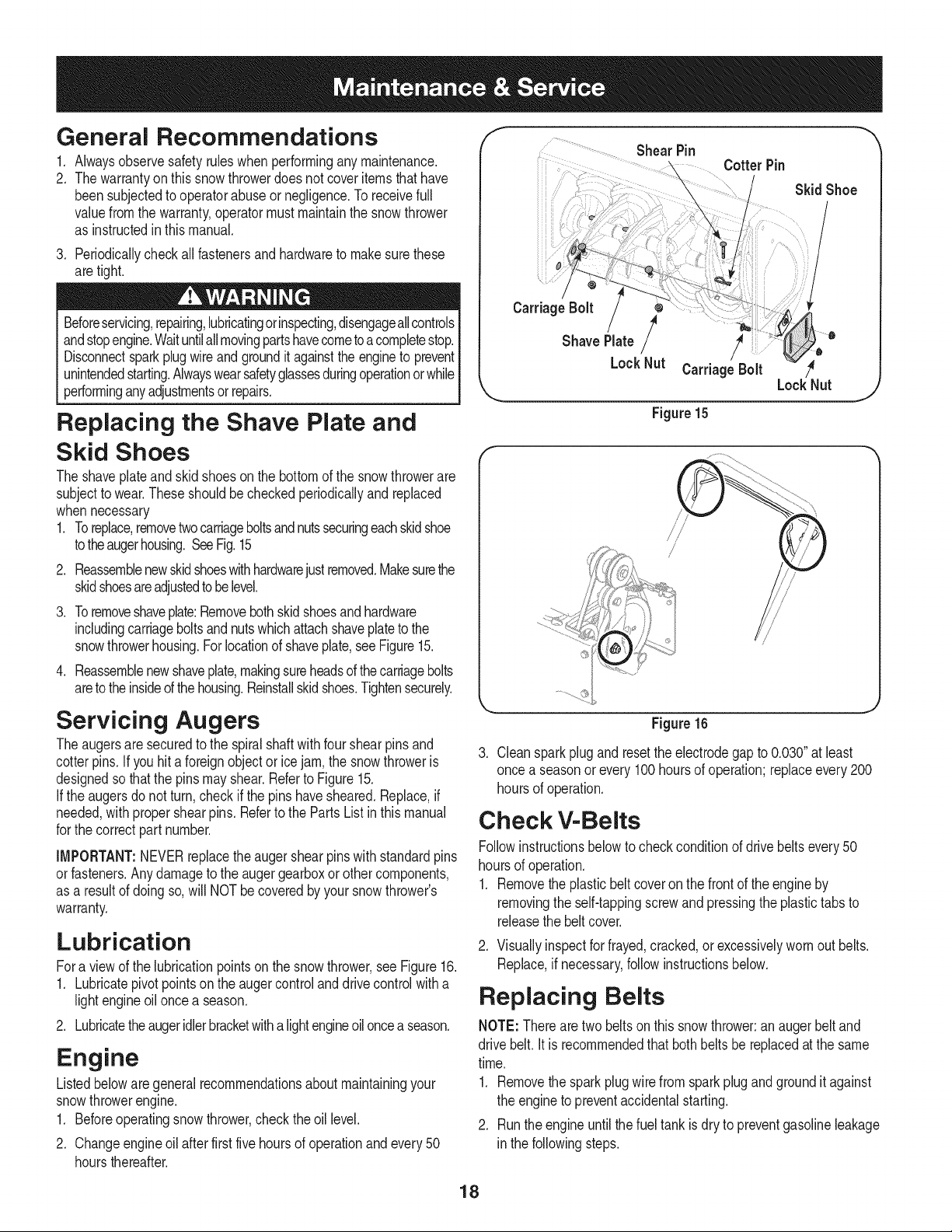
Checking Spark Plug
DO NOTcheckfor sparkwith spark plug removed.DO NOTcrank
enginewithsparkplugremoved.
Ifthe engine hasbeenrunning,the mufflerwill bevery hot. Be careful
notto touch the muffler.
NOTE: Checkthe sparkplug oncea seasonorevery25hoursof
operation.Changethe sparkplugoncea seasonor every100hours.
Toensureproperengine operation,the sparkplug mustbe properly
gappedandfreeof deposits.
1. Removethespark plug bootanduse a sparkplug wrenchto
removethe plug.See Figure13.
2. Visuallyinspectthe sparkplug.Discardthe sparkplugif thereis
apparentwear,or if the insulatoris crackedor chipped.Cleanthe
sparkplugwitha wirebrush if it is to be reused.
3. Measurethe pluggapwitha feelergauge.Correctas necessary
by bendingsideelectrode.See Figure14.The gapshouldbe set
to .02-.03inches(0.60-0.80ram).
4. Checkthatthe sparkplug washeris ingoodconditionandthread
the sparkplug in by handto preventcross-threading.
5. Afterthespark plug is seated,tightenwitha sparkplugwrenchto
compressthe washer.
NOTE:Wheninstallinga newsparkplug,tighten1/2-turnafterthe
sparkplugseatsto compressthe washer.Whenreinstallinga used
sparkplug,tighten 1/8-to 1/4-turnafter the sparkplug seatsto
compressthe washer.
The sparkplug mustbe tightenedsecurely.A loosesparkplug can
becomevet hotand can dama ethe enine.
Spark Rug
SparkPlug Boot
Figure13
Electrode
Figure14
17
General Recommendations
.
2.
Alwaysobservesafetyruleswhenperformingany maintenance.
Thewarrantyon thissnowthrowerdoesnot coveritemsthathave
beensubjectedto operatorabuseor negligence.To receivefull
valuefromthe warranty,operatormustmaintainthe snowthrower
as instructedin thismanual.
3. Periodicallycheckall fastenersand hardwareto makesurethese
aretight.
Beforeservicing,repairing,lubricatingorinspecting,disengageallcontrols
andstopengine.Waituntilallmovingpartshavecometoacompletestop.
Disconnectsparkplugwireandgroundit againsttheengineto prevent
unintendedstarting.Alwayswearsafetyglassesduringoperationor while
performinganyadjustmentsor repairs.
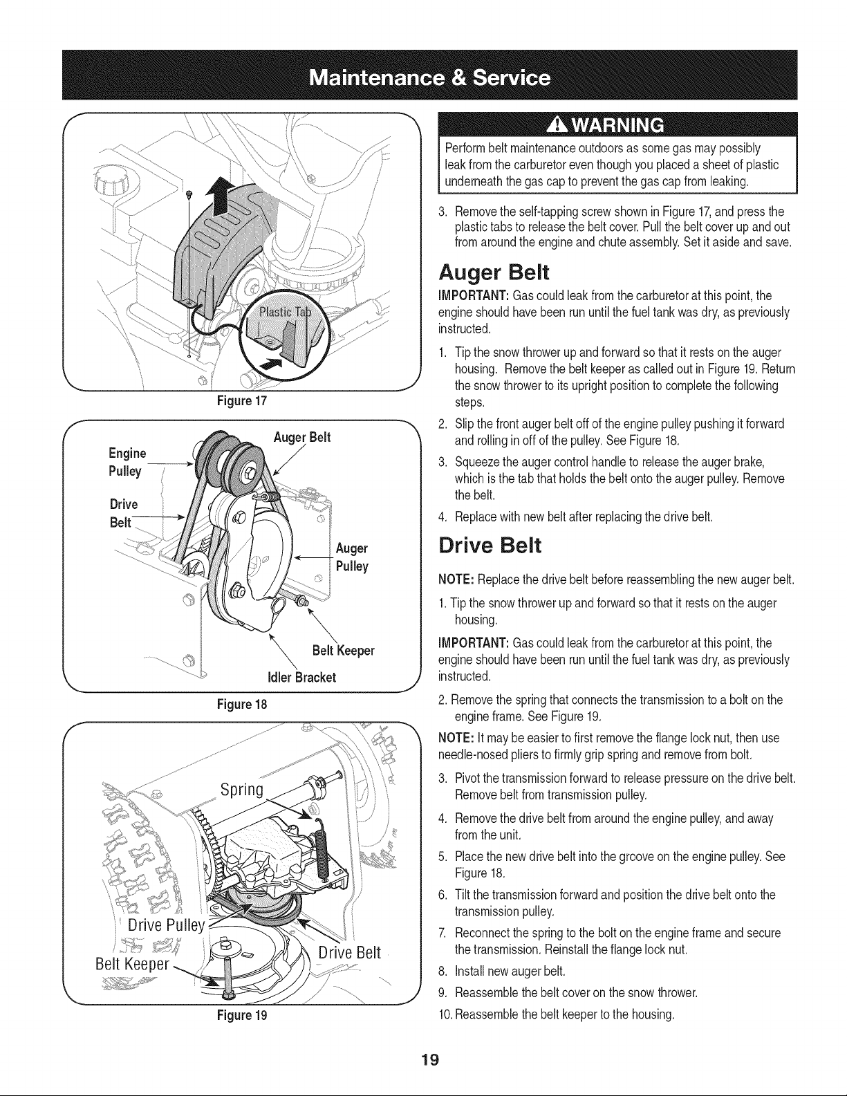
Replacing the Shave Plate and
Skid Shoes
The shaveplateand skid shoeson the bottomof the snowthrowerare
subjectto wear.Theseshouldbe checkedperiodicallyand replaced
whennecessary
1. Toreplace,removetwocarriageboltsandnutssecuringeachskidshoe
totheaugerhousing.SeeFig.15
.
3.
.
Reassemblenewskidshoeswithhardwarejustremoved.Makesurethe
skidshoesareadjustedtobe level.
Toremoveshaveplate:Removebothskid shoesand hardware
includingcarriageboltsandnutswhichattachshaveplateto the
snowthrowerhousing.Forlocationof shaveplate,see Figure15.
Reassemblenewshaveplate,makingsureheadsof thecarriagebolts
areto theinsideof thehousing.Reinstallskidshoes.Tightensecurely.
Servicing Augers
Theaugersaresecuredto the spiralshaftwithfourshearpins and
cotterpins. If you hit a foreignobjectorice jam,the snowthroweris
designedso that the pinsmayshear.Referto Figure15.
Ifthe augersdo notturn,checkif the pins havesheared.Replace,if
needed,with propershearpins.Referto the Parts List in this manual
for thecorrectpart number.
IMPORTANT:NEVERreplacetheauger shearpinswithstandardpins
orfasteners.Anydamageto the auger gearboxor othercomponents,
as a resultof doingso,will NOTbe coveredby yoursnowthrower's
warranty.
Lubrication
Fora viewof the lubricationpointson the snowthrower,see Figure16.
1. Lubricatepivot pointson the auger controland drivecontrolwitha
lightengineoil oncea season.
2. Lubricatetheaugeridlerbracketwithalightengineoil oncea season.
Engine
Listedbeloware generalrecommendationsaboutmaintainingyour
snowthrowerengine.
1. Beforeoperatingsnowthrower,checkthe oil level.
2. Changeengineoil afterfirstfive hoursof operationandevery50
hoursthereafter.
f Shear Pin
CotterPin
_iiiii
Skid Shoe
CarriageBolt
Shave P,ate / /
LockNut CarriageBolt /4
,_ LockNut j
Figure 15
i/
/ /
/
/
Figure16
3. Cleansparkplug and resetthe electrodegap to 0.030"at least
once a seasonor every 100hoursof operation;replaceevery200
hoursof operation.
Check V-Belts
Followinstructionsbelowto checkconditionof drivebeltsevery50
hoursof operation.
1. Removethe plasticbeltcoveron the front of theengineby
removingthe self-tappingscrewandpressingthe plastictabsto
releasethe beltcover.
2. Visuallyinspectforfrayed,cracked,or excessivelywornout belts.
Replace,if necessary,followinstructionsbelow.
Replacing Belts
NOTE: Therearetwobeltsonthis snowthrower:anauger beltand
drive belt. It is recommendedthatbothbelts be replacedatthe same
time.
1. Removethe spark plugwirefrom sparkplugandgrounditagainst
the engineto preventaccidentalstarting.
2. Runtheengineuntilthe fueltank isdry to preventgasolineleakage
inthe followingsteps.
18
f
Figure17
J
f
Engine
Pulley
Drive
/
Figure 18
Figure19
f
'Drive
Belt Keeper
J
Performbelt maintenanceoutdoorsas somegas maypossibly
leakfrom the carburetoreventhoughyou placeda sheetof plastic
underneaththe gas capto preventthegas cap from leaking.
3. Removethe self-tappingscrewshownin Figure17,and pressthe
plastictabsto releasethe beltcover.Pullthe beltcover up and out
fromaroundthe engineand chuteassembly.Setit asideandsave.
Auger Belt
IMPORTANT:Gascould leakfromthecarburetorat this point,the
engineshouldhavebeenrununtilthe fuel tankwasdry,as previously
instructed.
1. Tip the snowthrowerup and forwardso that it restsonthe auger
housing. Removethe beltkeeperas calledout in Figure19.Return
the snow throwerto its uprightpositionto completethe following
steps.
2. Slipthe frontaugerbelt off of theenginepulleypushingit forward
and rollinginoff of the pulley.See Figure18.
3. Squeezethe augercontrolhandleto releasetheaugerbrake,
whichis the tab that holdsthe beltonto theaugerpulley.Remove
the belt.
4. Replacewithnew beltafter replacingthedrive belt.
Drive Belt
NOTE:Replacethe drivebelt beforereassemblingthe newaugerbelt.
1.Tip the snowthrowerupandforwardso thatit restson the auger
housing.
IMPORTANT:Gascould leakfromthecarburetorat this point,the
engineshouldhavebeenrununtilthe fuel tankwasdry,as previously
instructed.
2. Removethe springthatconnectsthe transmissionto a bolton the
engineframe.See Figure19.
NOTE:It maybe easierto first removethe flangelock nut,then use
needle-nosedpliersto firmlygripspringand removefrom bolt.
.
4.
5.
6.
7.
Pivotthetransmissionforwardto releasepressureon the drivebelt.
Removebelt fromtransmissionpulley.
Removethe drivebeltfromaroundthe enginepulley,andaway
fromthe unit.
.
9.
Placethe newdrivebelt intothe grooveon the enginepulley.See
Figure18.
Tilt thetransmissionforwardandpositionthe drivebeltonto the
transmissionpulley.
Reconnectthe springto the bolton the engineframeand secure
the transmission.Reinstallthe flangelocknut.
Installnewaugerbelt.
Reassemblethebelt coveron the snowthrower.
10.Reassemblethebelt keeperto the housing.
19
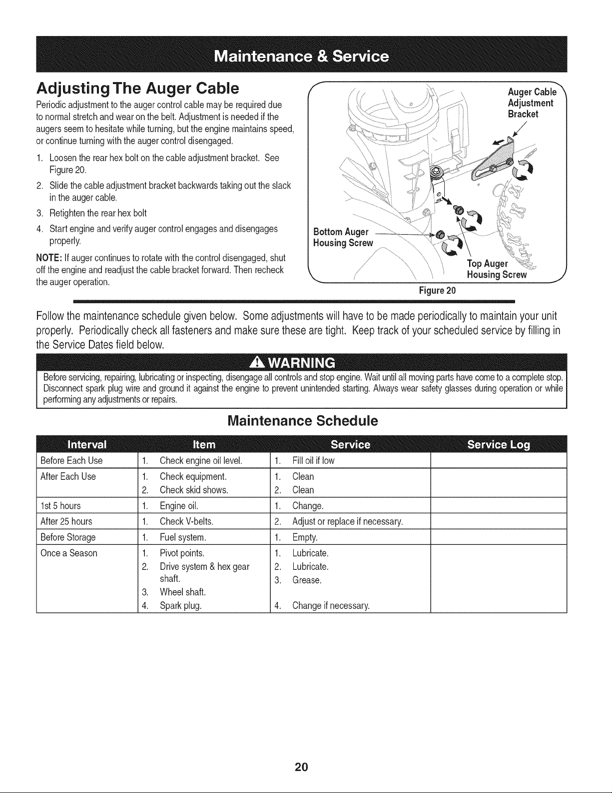
Adjusting The Auger Cable
Periodicadjustmentto theauger controlcablemaybe requireddue
to normalstretchandwearon the belt.Adjustmentis neededifthe
augersseemto hesitatewhileturning,but theengine maintainsspeed,
orcontinueturningwiththe augercontroldisengaged.
1. Loosenthe rearhex bolton the cableadjustmentbracket. See
Figure20.
2. Slidethe cableadjustmentbracketbackwardstakingout the slack
inthe augercable.
3. Retightenthe rear hexbolt
4. Startengineandverifyauger controlengagesanddisengages
properly.
NOTE: If augercontinuesto rotatewiththe controldisengaged,shut
offthe engineand readjustthe cablebracketforward.Then recheck
theauger operation.
f
AugerCable_
Adjustment
Bracket
/ _i TopAuger
,_ / , _ Housing Screw
Figure20
J
Followthe maintenanceschedule given below. Some adjustments will have to be made periodicallyto maintainyour unit
properly. Periodicallycheck all fasteners and make sure these are tight. Keep track of your scheduled service by filling in
the Service Dates field below.
Beforeservicing,repairing,lubricatingor inspecting,disengageallcontrolsandstopengine.Waituntilallmovingpartshavecometo a completestop.
Disconnectspark plugwire and groundit againstthe engineto preventunintendedstarting.Alwayswearsafetyglassesduringoperationor while
performinganyadjustmentsorrepairs.
Maintenance Schedule
BeforeEachUse
AfterEachUse
1st5 hours
After25hours
BeforeStorage
Oncea Season
1. Checkengineoil level.
1. Checkequipment.
2. Checkskid shows.
1. Engineoil.
1. CheckV-belts.
1. Fuelsystem.
1. Pivotpoints.
2. Drivesystem& hex gear
shaft.
3. Wheelshaft.
4. Sparkplug.
1. Filloil if low
1. Clean
2. Clean
1. Change.
2. Adjustor replaceif necessary.
1. Empty.
1. Lubricate.
2. Lubricate.
3. Grease.
4. Changeif necessary.
2O
Ifthe snowthrowerwillnot be usedfor30 daysor longer,or if it is the endof the snowseasonwhenthe last possibilityof snowis gone,the
equipmentneedsto be storedproperly.Followstorageinstructionsbelowto ensuretop performancefromthe snowthrowerfor manymoreyears.
PREPARING ENGINE
Short=Term Storage
It is importantto preventgum depositsfromforminginessentialfuel
systempartsof the enginesuchas the carburetor,fuel filter,fuel hose,
ortankduringshort-termstorage(15-30days).Topreventthis,treat
thefuel systemusinga fuel stabilizer.
Fuelstabilizer(suchas STA-BILTM or ULTRA-FRESHTM) is an accept-
ablealternativein minimizingtheformationof fuel gumdepositsduring
storage.Addstabilizerto gasolineinfuel tank or storagecontainer.
Alwaysfollowmix ratiofound on stabilizercontainer.Runengineat
least10minutesafteraddingstabilizerto allow it to reachthe carbure-
tor.
Neverstoresnowthrowerwithfuel intank indoorsor inpoorlyventi-
latedareas,wherefuel fumesmayreachan openflame,sparkor pilol
lightas on a furnace,waterheater,clothesdryer or gas appliance.
PREPARING SNOW THROWER
• Whenstoringthe snowthrowerin anunventilatedormetal stor-
age shed,careshouldbetakento rustprooftheequipment.Using
a light oilor silicone,coattheequipment,especiallyanychains,
springs,bearingsandcables.
• Removealldirt fromexteriorof engineand equipment.
• Followlubricationrecommendations.
• Storeequipmentin a clean,dry area.
Alcoholblendedfuels(calledgasoholor usingethanolor methanol)
canattract moisturewhichleadsto separationandformationof acids
duringstorage.Acidicgas can damagethefuel systemof an engine
_wh e n storage.
Long=Term Storage
Toavoidengineproblems,the fuel systemshouldbeemptiedbefore
storagefor30 daysor longer.
Fuelleft in engineduringwarmweatherdeterioratesand will cause
seriousstartingproblems.
1. Runthe engineuntilthe fuel tank is emptyandit stopsdueto lack
of fuel. Do notattemptto pour fuelfromthe engine.
Neveruseengineor carburetorcleaningproductsin the fueltankor
permanentdamagemayoccur.
.
Removethe sparkplug and pourone (1) ounceof engineoil
throughthe sparkplug hole into the cylinder.Coversparkplughole
witha ragandcrankthe engineseveraltimesto distributethe oil.
Replacesparkplug.
21
Beforeperforminganytyped maintenance/service,disengageall
controlsandstoptheengine.Waituntilallmovingpartshavecometo
a completestop.Disconnectsparkplugwireandgroundit againstthe
engineto preventunintendedstarting.Alwayswearsafetyglassesduring
operationor whileperforminganyadjustmentsorrepairs.
This sectionaddresses minor service issues.Tolocate the nearestSearsServiceCenteror to scheduleservice,simplycontactSears
at 1-800-4-MY-HOME®.
Enginefailsto start
Enginerunserratically
1. Chokecontrolnot in ONposition.
2. Sparkplug wiredisconnected.
3. Faultysparkplug.
4. Fueltankemptyor stalefuel.
5. Enginenot primed.
6. Safetykey not inserted.
1. EnginerunningonCHOKE.
2. Stalefuel.
3. Wateror dirt infuel system.
4. Carburetoroutof adjustment.
1. Carburetornotadjustedproperly.
1. Loosepartsordamagedauger.
Engineoverheats
Excessivevibration
Lossof power 1. Sparkplugwireloose.
2. Gascap vent hole plugged.
Unitfailsto propelitself 1. Drivecablein needof adjustment.
2. Drivebeltlooseor damaged.
Unitfailsto dischargesnow 1. Chuteassemblyclogged.
2. Foreignobjectlodgedin auger.
3. Augercable in need of adjustment.
4. Augerbeltlooseor damaged.
5. Shearpin(s)sheared.
1. Movechokecontrolto ON position.
2. Connectwireto sparkplug.
3. Clean,adjustgap, or replace.
4. Filltankwith clean,fresh gasoline.
5. Primeengineas instructedin theOperationSection.
6. Insertkeyfullyintothe switch.
1. Movechokecontrolto OFFposition.
2. Filltankwith clean,fresh gasoline.
3. Drainfuel tank.Refillwithfreshfuel.
4. ContactyourSearsParts& RepairCenter.
1. ContactyourSearsParts& RepairCenter.
1. Stopengineimmediatelyand disconnectspark plug
wire.Tightenall boltsandnuts.If vibrationcontinues,
haveunit servicedby a SearsParts& RepairCenter.
1. Connectandtighten sparkplugwire.
2. Removeice and snowfrom gas cap. Be certainvent
holeis clear.
1. Adjustdrivecontrolcable.Referto Serviceand
Maintenancesection.
2. Replacedrivebelt.Referto Service & Maint.section.
1. Stopengineimmediatelyand disconnectspark plug
wire.Cleanchuteassemblyandinsideof auger
housingwithclean-outtoolor a stick.
2. Stopengine immediatelyand disconnectspark plug
wire.Removeobject from augerwith clean-outtool
or a stick.
3. Adjustaugercontrolcable.Referto Assembly
section.
4. Replaceaugerbelt. Referto Serviceand Mainte-
nancesection.
5. Replacewith newshearpin(s).
o Find this and all your other product rnanua[s online.
o Get answers from our team of home experts.
o Get a personatized maintenance plan for your home,
o Find information and tools to help with home projects.
22
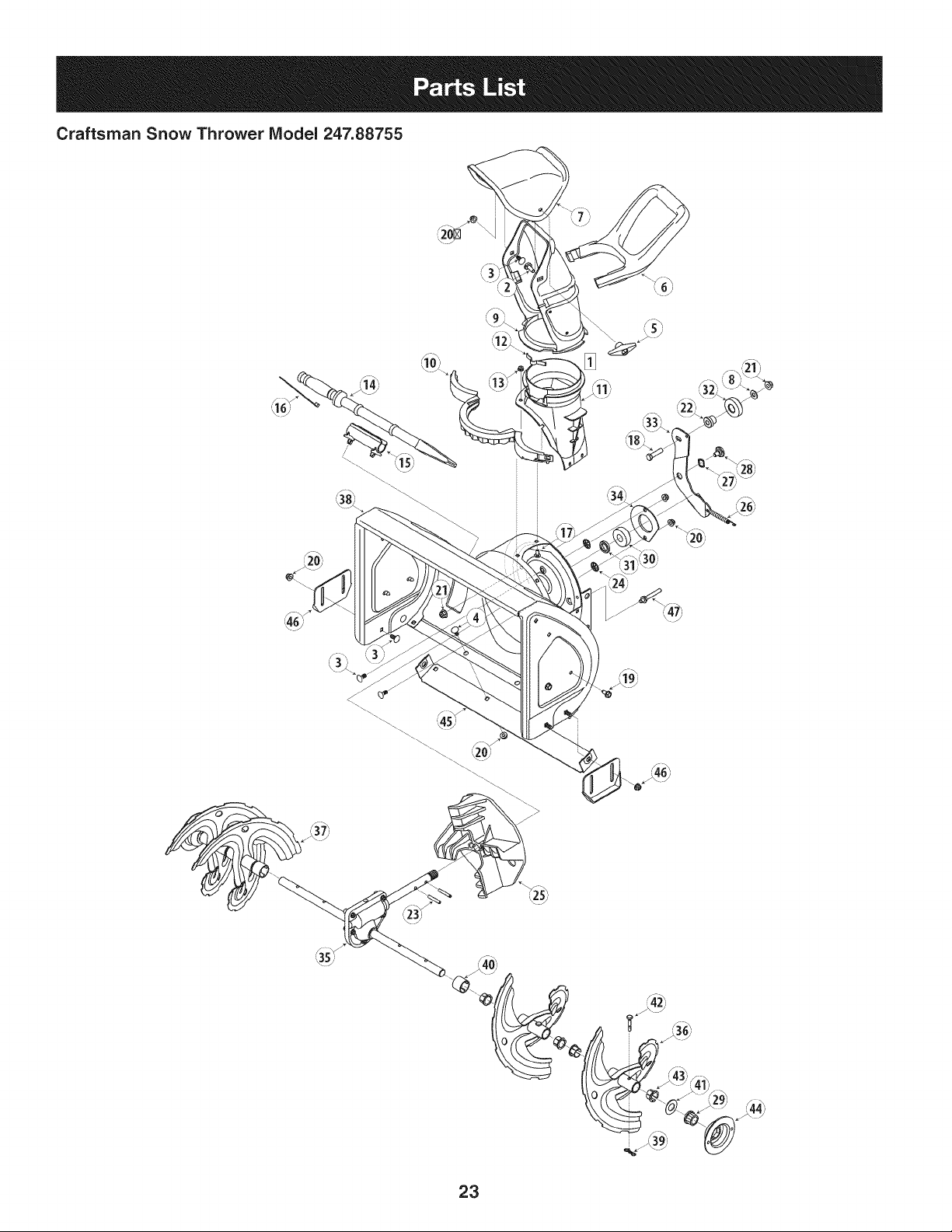
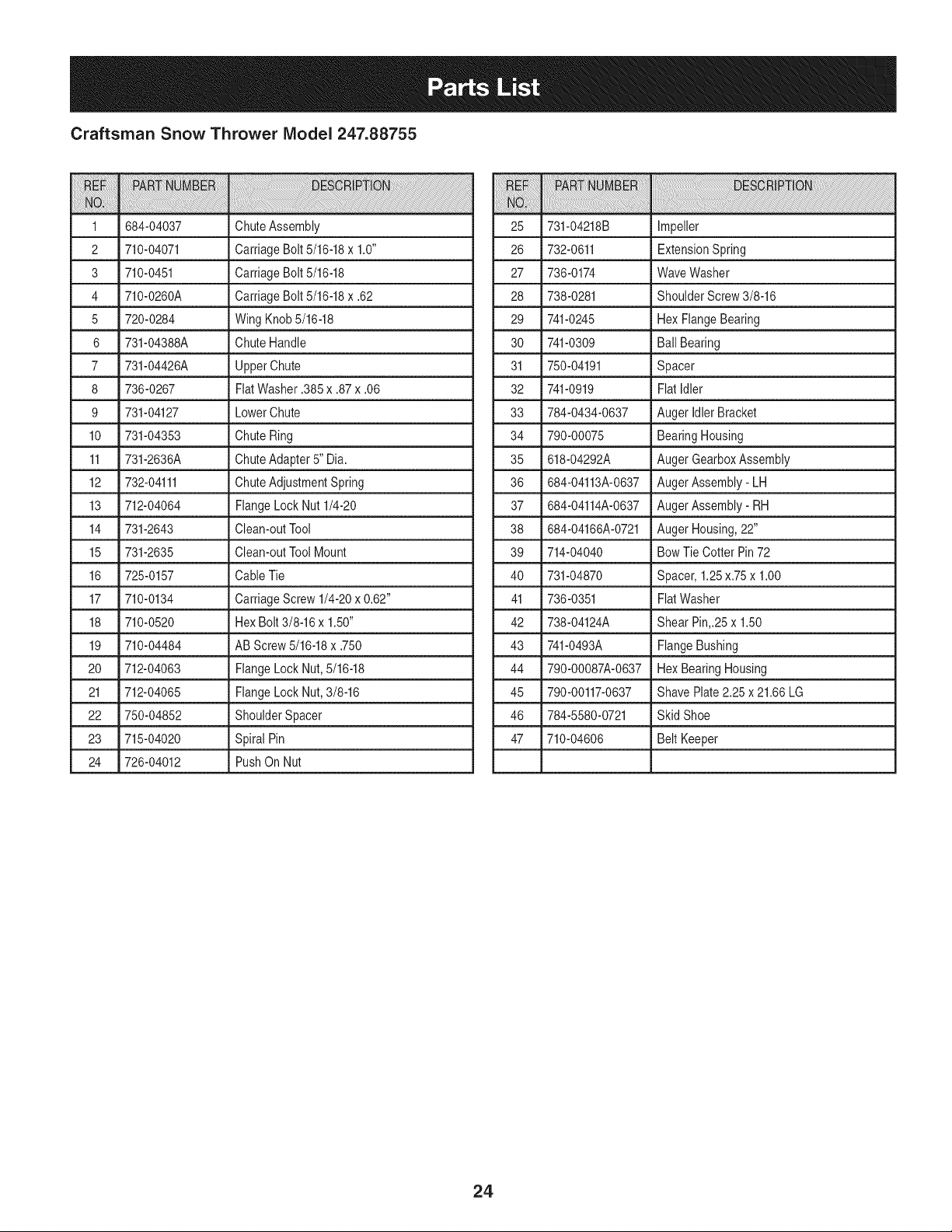
Craftsman Snow Thrower Model 247.88755
/
23
Craftsman Snow Thrower IViodel 247.88755
iiiiii!ii!ii_i_!i_!ililililiiiiii_iiiiiiiiiiiiiiiiili_i_iiiiili_!_i_!i!_ii_i!_i!iii!ilili;iiiiiiiiiiii______________________________________________________________________________________________________________________________________i______iiiiiiiiiiiiiiiiiiiiiiiiiiiiiiiiiiiiiiiiiiiiiiiiiiiiiiiiiiiiiiiiiiiiiiiiiiiiiiiiii!i_ii_
iiiiiiiiiiiiiiiiili!!ili! ! !!!!i!!ii!i!i!iiii!iiiiiiiiiii!_i!!_i!i!!i!!i!!i!_i!_iii!i_i_i_i_i_!_i_!i__i__i_!i!!!__i__!!!i!!_!!i_i__!!_!!_!!!i!i!i!i!!!i!i!i!!!i!_!_!_!_i__i__i__i_!!_!!_!i_ii_i_!_i_i!i!i!_!i_!!__i__i__i_!_i!!iiiiiiii!ii!_ii!i!iii!iiiiii!ii!!ii!!i!iiiiii!ii!i!i!i!i!i!iiiiii!ii!i!i!i!i_iii_i______!!i__!__!i!ii_ii_ii__i__i_!i_!___i___!!_!_i__i__i__i__!__i_i!_!i_i!_!_!_!_!_!_!_!_!!!i!!ii!!ii!iiiiiii!iii!i!iii!iii!iii!iii!iii!!ii!!!!!!!!!!!i!i!iiiiii!iiii!!iii!iiii!i!i!!ii!!______i_i_i!i_!_i!i!!i!!!!iiiiii!i!i!i!!!ii!_!i!!___i___i!_!!ii!!iiii!i!!ii!!i!iiiiii!ii!!ii!!i!iiiiii!ii!!ii!!i!iiiiii!ii!!ii!!i!iiiiii!ii!!ii!!i!iiiiii!ii!!ii!!i!iiiiii!ii!!ii!!i!iiiiii!ii!!ii!!i!iiiiii!ii!!ii!!i!iiiiii!ii!!ii!!i!iiiiii!ii!!ii!!i!iiiiii!ii!!ii!!i!iiiiii!ii!!ii!!i!iiiiii!ii!!ii!!i!iiiiii!ii!!ii!!i!iiiiii!ii!!ii!!ii_______
1 684-04037 ChuteAssembly 25
2 710-04071 CarriageBolt 5/16-18x 1.0" 26
3 710-0451 CarriageBolt 5/16-18 27
4 710-0260A CarriageBolt 5/16-18x .62 28
5 720-0284 WingKnob5/16-18 29
6 731-04388A ChuteHandle 30 741-0309
7 731-04426A UpperChute 31 750-04191
8 736-0267 FiatWasher.385 x .87x .06 32 741-0919
9 731-04127 LowerChute 33 784-0434-0637
10 731-04353 ChuteRing 34 790-00075
11 731-2636A ChuteAdapter5" Dia. 35 618-04292A
12 732-04111 ChuteAdjustmentSpring 36 684-04113A-0637
13 712-04064 FlangeLock Nut 1/4-20 37 684-04114A-0637
14 731-2643 Clean-outTool 38 684-04166A-0721
15 731-2635 Clean-outToolMount 39 714-04040
16 725-0157 CableTie 40 731-04870
17 710-0134 CarriageScrew 1/4-20x 0.62" 41 736-0351
18 710-0520 HexBolt 3/8-16x 1.50" 42 738-04124A
19 710-04484 AB Screw5/16-18x .750 43 741-0493A
20 712-04063 FlangeLockNut,5/16-18 44 790-00087A-0637
21 712-04065 FlangeLock Nut,3/8-16 45 790-00117-0637
22 750-04852 ShoulderSpacer 46 784-5580-0721
23 715-04020 Spiral Pin 47 710-04606
24 726-04012 PushOn Nut
iiiiiiiiiiiiiiili!:!ili! i i!i!iiii!!iiiiiiii!i!!!iiiiiiii!iiiiiiii!i!i!i_!_!!_!i_!__i__i__i_!_!!!_!___i_!_i_i_i_i!i_!_!_!_i_!_!_!_!_!_!_!_!_!_!_!_!_i_i_i_!_i_i_i!__!_i_i__!!___i!!ii_i!i!i!_!_!___!_!_!_i_ii_i!_i!_i______!___!i_i!_!i!i___!_!!!!!_i!ii!!ii___i__!__i!_!_i_i_i_i!ii__!
731-04218B Impeller
732-0611 ExtensionSpring
736-0174 WaveWasher
738-0281 ShoulderScrew3/8-16
741-0245 Hex FlangeBearing
Ball Bearing
Spacer
FlatIdler
Auger IdlerBracket
BearingHousing
AugerGearboxAssembly
AugerAssembly- LH
AugerAssembly- RH
AugerHousing,22"
Bow Tie Cotter Pin72
Spacer,1.25x.75 x 1.00
FlatWasher
Shear Pin,.25x 1.50
FlangeBushing
Hex BearingHousing
Shave Plate2.25 x 21.66 LG
Skid Shoe
Belt Keeper
24
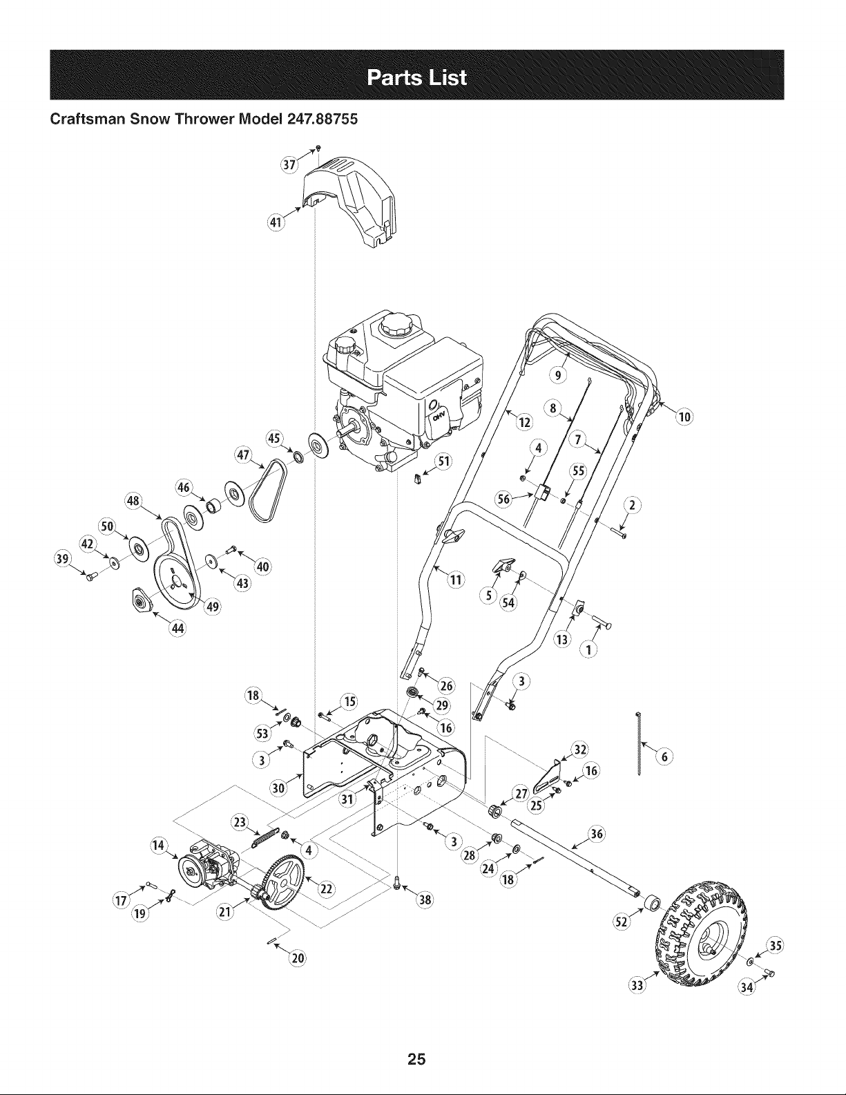
Craftsman Snow Thrower Model 247.88755
25
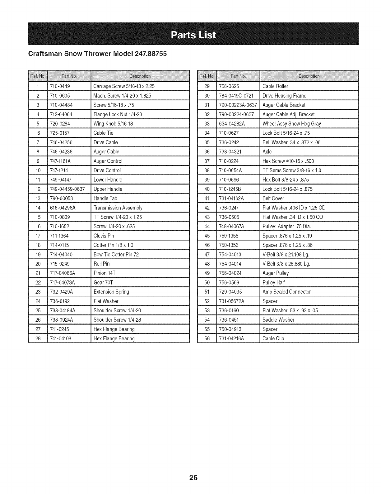
Craftsman Snow Thrower IViodel 247.88755
1 _710-0449 _ CarriageScrew5/16-18x 2.25
2 710-0605 Mach.Screw 1/4-20x 1.825
3 710-04484 Screw5/16-18x .75
4 712-04064 FlangeLock Nut 1/4-20
5 720-0284 WingKnob 5/16-18
6 725-0157 Cable Tie
7 746-04256 DriveCable
8 746-04236 AugerCable
9 747-1161A AugerControl
10 747-1214 DriveControl
11 749-04147 LowerHandle
12
749-04459-0637 Upper Handle
13 790-00053 HandleTab
14 618-04296A TransmissionAssembly
15 710-0809 TT Screw 1/4-20x 1.25
16 710-1652 Screw1/4-20x .625
17 711-1364 Clevis Pin
18 714-0115 Cotter Pin 1/8x 1.0
19 714-04040 Bow Tie Cotter Pin72
20 715-0249 Roll Pin
21 717-04066A Pinion14T
22 717-04073A Gear70T
23 732-0429A ExtensionSpring
24 736-0192 FiatWasher
25 738-04184A ShoulderScrew1/4-20
26 738-0924A ShoulderScrew1/4-28
27 741-0245 Hex FlangeBearing
28 741-04108 Hex FlangeBearing
29 756-0625 Cable Roller
30 784-0419C-0721 DriveHousingFrame
31 790-00223A-0637 AugerCable Bracket
32 790-00224-0637 AugerCable Adj. Bracket
33 634-04282A Wheel AssySnow HogGray
34 710-0627 LockBolt 5/16-24x .75
35 736-0242 BellWasher.34 x .872x .06
36 738-04321 Axle
37 710-0224 HexScrew#10-16x .500
38 710-0654A TT SemsScrew 3/8-16x 1.0
39 710-0696 HexBolt 3/8-24x .875
40 710-1245B LockBolt 5/16-24x .875
41 731-04162A BeltCover
42 736-0247 FiatWasher.406ID x 1.25OD
43 736-0505 FiatWasher.34 ID x 1.50OD
44 748-04067A Pulley:Adapter.75 Dia.
45 750-1355 Spacer .876x 1.25x .19
46 750-1356 Spacer .876x 1.25x .86
47 754-04013 V-Belt 3/8 x 21.108Lg.
48 754-04014 V-Belt 3/8 x 26.680Lg.
49 756-04024 Auger Pulley
50 756-0569 PulleyHalf
51 729-04035 Amp SealedConnector
52 731-05672A Spacer
53 736-0160 FiatWasher.53 x .93x .05
54 736-0451 Saddle Washer
55 750-04913 Spacer
56 731-04216A CableClip
26
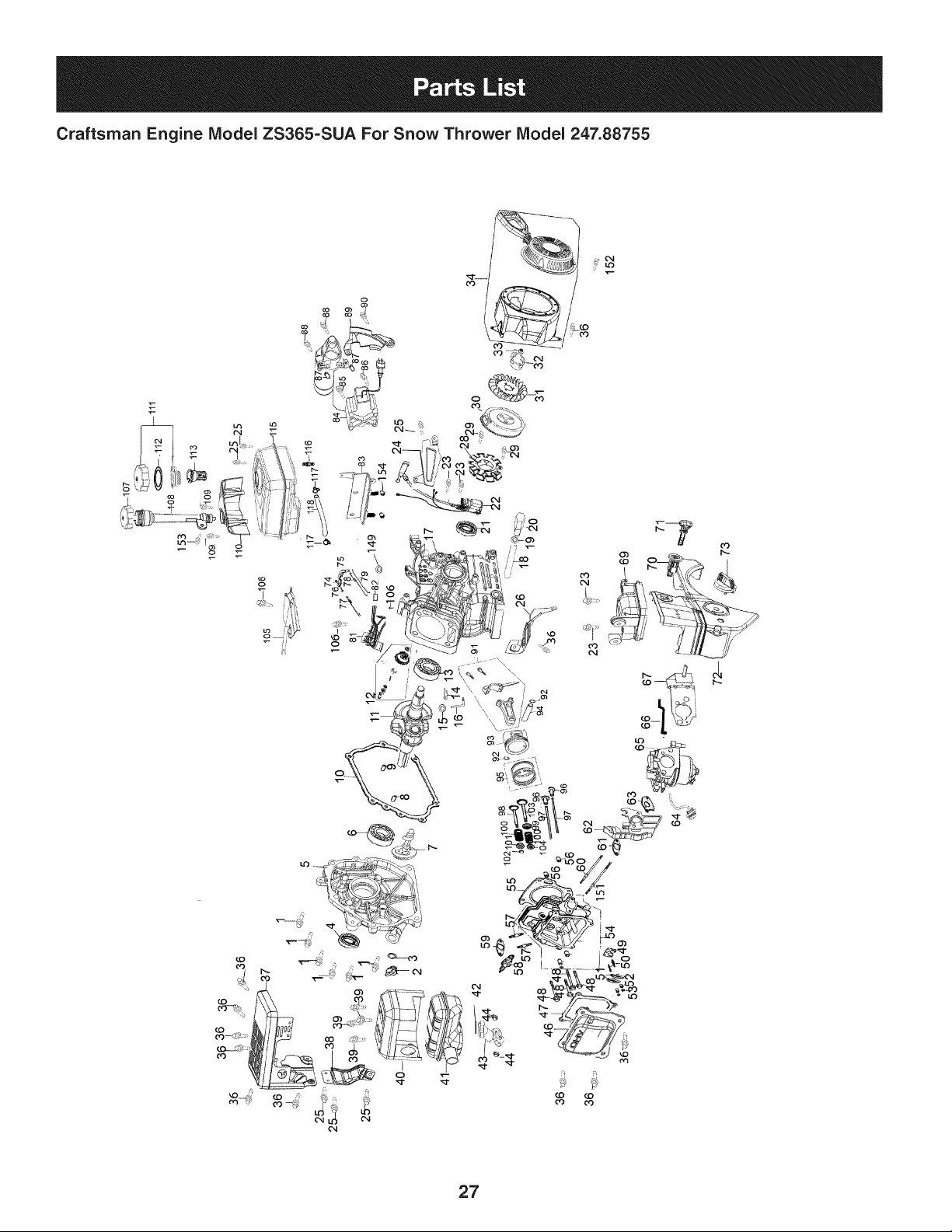
Craftsman Engine Model ZS365-SUA For Snow Thrower Model 247.88755
7
o3
27
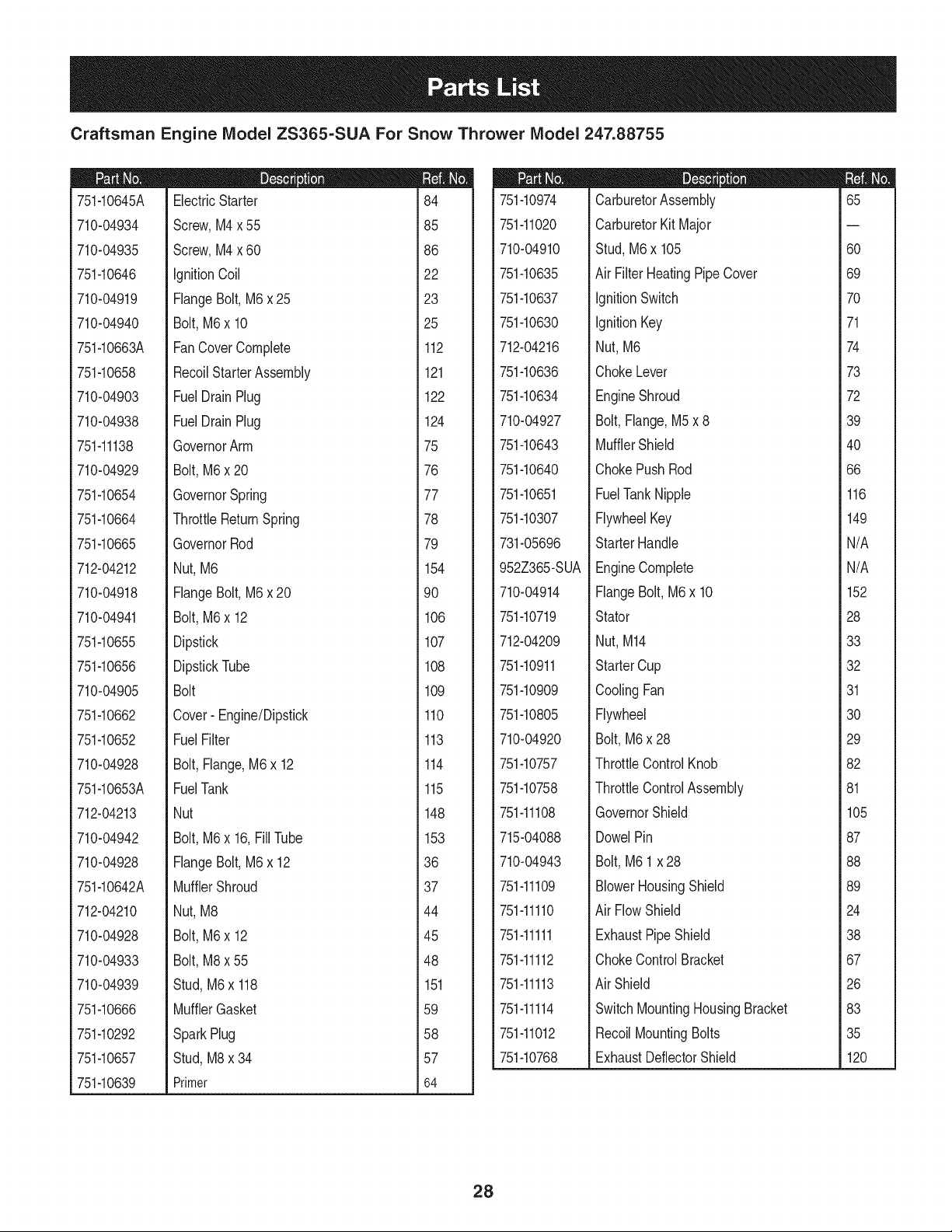
Craftsman Engine IViodel ZS365=SUA For Snow Thrower IViodel 247.88755
751-10645A
710-04934
710-04935
751-10646
710-04919
710-04940
751-10663A
751-10658
710-04903
710-04938
751-11138
710-04929
751-10654
751-10664
751-10665
712-04212
710-04918
710-04941
751-10655
751-10656
710-04905
751-10662
751-10652
710-04928
751-10653A
712-04213
710-04942
710-04928
751-10642A
712-04210
710-04928
710-04933
710-04939
751-10666
751-10292
751-10657
751-10639
D = O O
ElectricStarter
Screw,M4 x 55
Screw,M4 x 60
IgnitionCoil
FlangeBolt, M6x 25
Bolt,M6 x 10
FanCoverComplete
RecoilStarterAssembly
FuelDrainPlug
FuelDrainPlug
GovernorArm
Bolt,M6 x 20
GovernorSpring
ThrottleReturnSpring
GovernorRod
Nut, M6
FlangeBolt, M6x 20
Bolt,M6 x 12
Dipstick
DipstickTube
Bolt
Cover- Engine/Dipstick
FuelFilter
Bolt,Flange,M6x 12
FuelTank
Nut
Bolt,M6 x 16,FillTube
FlangeBolt, M6x 12
MufflerShroud
Nut, M8
Bolt,M6 x 12
Bolt,M8 x 55
Stud,M6x 118
MufflerGasket
SparkPlug
Stud,M8x 34
Primer
m
i
i
184
i
i
185
i
i
i
i86
!
i
i
122
i
i
123
i
i
i
i25
!
i
1112
1
1
1
1121
1
1
1
i122
!
i
1124
1
1
1
_75
1
1
1
i76
!
i
_77
1
1
1
i78
!
!
i
_79
1
1
1154
1
1
1
i90
!
i
1
1106
1
1
1107
1
1
1
i108
!
i
1
1109
1
1
1110
1
1
1
i113
!
i
1114
1
1
1
1115
1
1
1
i148
!
i
1153
1
1
1
_36
1
1
1
i37
!
i
_44
1
1
1
i45
!
!
i
_48
1
1
i 151
1
1
1
i59
!
i
1
_58
1
1
_57
1
1
1
i64
I
751-10974
751-11020
710-04910
751-10635
751-10637
751-10630
712-04216
751-10636
751-10634
710-04927
751-10643
751-10640
751-10651
751-10307
731-05696
952Z365-SUA
710-04914
751-10719
712-04209
751-10911
751-10909
751-10805
710-04920
751-10757
751-10758
751-11108
715-04088
710-04943
751-11109
751-11110
751-11111
751-11112
751-11113
751-11114
751-11012
751-10768
m = O O
CarburetorAssembly
CarburetorKit Major
Stud,M6 x 105
Air Filter HeatingPipe Cover
IgnitionSwitch
IgnitionKey
Nut,M6
ChokeLever
EngineShroud
Bolt,Flange,M5x 8
MufflerShield
ChokePushRod
FuelTankNipple
FlywheelKey
StarterHandle
EngineComplete
FlangeBolt,M6 x 10
Stator
Nut,M14
StarterCup
CoolingFan
Flywheel
Bolt,M6x 28
ThrottleControlKnob
ThrottleControlAssembly
GovernorShield
DowelPin
Bolt,M6 1 x 28
BlowerHousingShield
Air FlowShield
ExhaustPipeShield
ChokeControlBracket
Air Shield
SwitchMountingHousingBracket
RecoilMountingBolts
ExhaustDeflectorShield
m
65
60
69
70
71
74
73
72
39
40
66
116
149
N/A
N/A
152
28
33
32
31
30
29
82
81
105
87
88
89
24
38
67
26
83
35
120
28
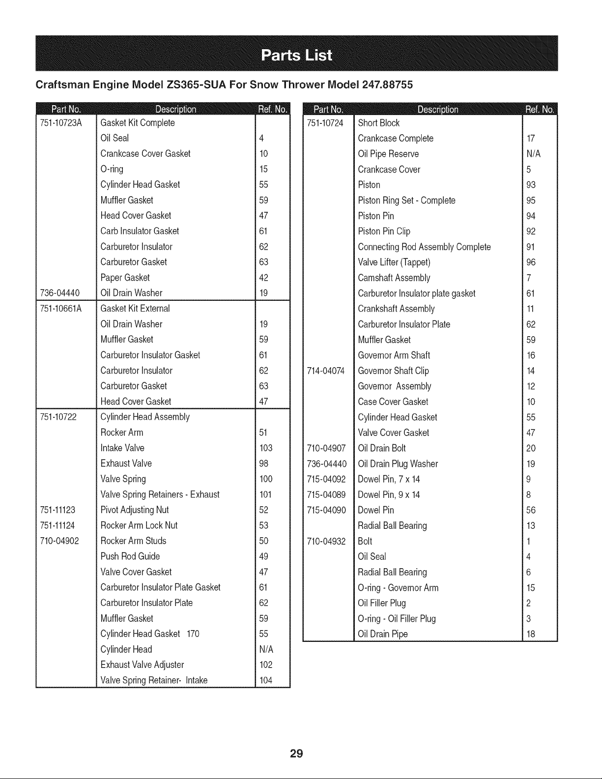
Craftsman Engine IViodel ZS365-SUA For Snow Thrower IViodel 247.88755
751-10723A
736-04440
751-10661A
751-10722
751-11123
751-11124
710-04902
I = O
GasketKitComplete
OilSeal 4
CrankcaseCoverGasket 10
O-ring 15
CylinderHeadGasket 55
MufflerGasket 59
HeadCoverGasket 47
CarbInsulatorGasket 61
CarburetorInsulator 62
CarburetorGasket 63
PaperGasket 42
Oil DrainWasher 19
GasketKit External
Oil DrainWasher 19
MufflerGasket 59
CarburetorInsulatorGasket 61
CarburetorInsulator 62
CarburetorGasket 63
HeadCoverGasket 47
CylinderHeadAssembly
RockerArm 51
IntakeValve 103
ExhaustValve 98
ValveSpring 100
ValveSpringRetainers-Exhaust 101
PivotAdjustingNut 52
RockerArm LockNut 53
RockerArm Studs 50
PushRodGuide 49
ValveCoverGasket 47
CarburetorInsulatorPlateGasket 61
CarburetorInsulatorPlate 62
MufflerGasket 59
CylinderHeadGasket 170 55
CylinderHead N/A
ExhaustValveAdjuster 102
ValveSpringRetainer-Intake 104
751-10724
714-04074
710-04907
736-04440
715-04092
715-04089
715-04090
710-04932
D = O
ShortBlock
CrankcaseComplete
OilPipeReserve
CrankcaseCover
Piston
PistonRingSet- Complete
PistonPin
PistonPinClip
ConnectingRodAssemblyComplete
ValveLifter(Tappet)
CamshaftAssembly
CarburetorInsulatorplategasket
CrankshaftAssembly
CarburetorInsulatorPlate
MufflerGasket
GovernorArm Shaft
GovernorShaft Clip
GovernorAssembly
CaseCoverGasket
CylinderHeadGasket
ValveCoverGasket
OilDrainBolt
OilDrainPlug Washer
DowelPin,7 x 14
DowelPin,9 x 14
DowelPin
RadialBall Bearing
Bolt
OilSeal
RadialBall Bearing
O-ring- GovernorArm
OilFillerPlug
O-ring- Oil FillerPlug
OilDrainPipe
m
17
N/A
5
93
95
94
92
91
96
7
61
11
62
59
16
14
12
10
55
47
20
19
9
8
56
13
1
4
6
15
2
3
18
29
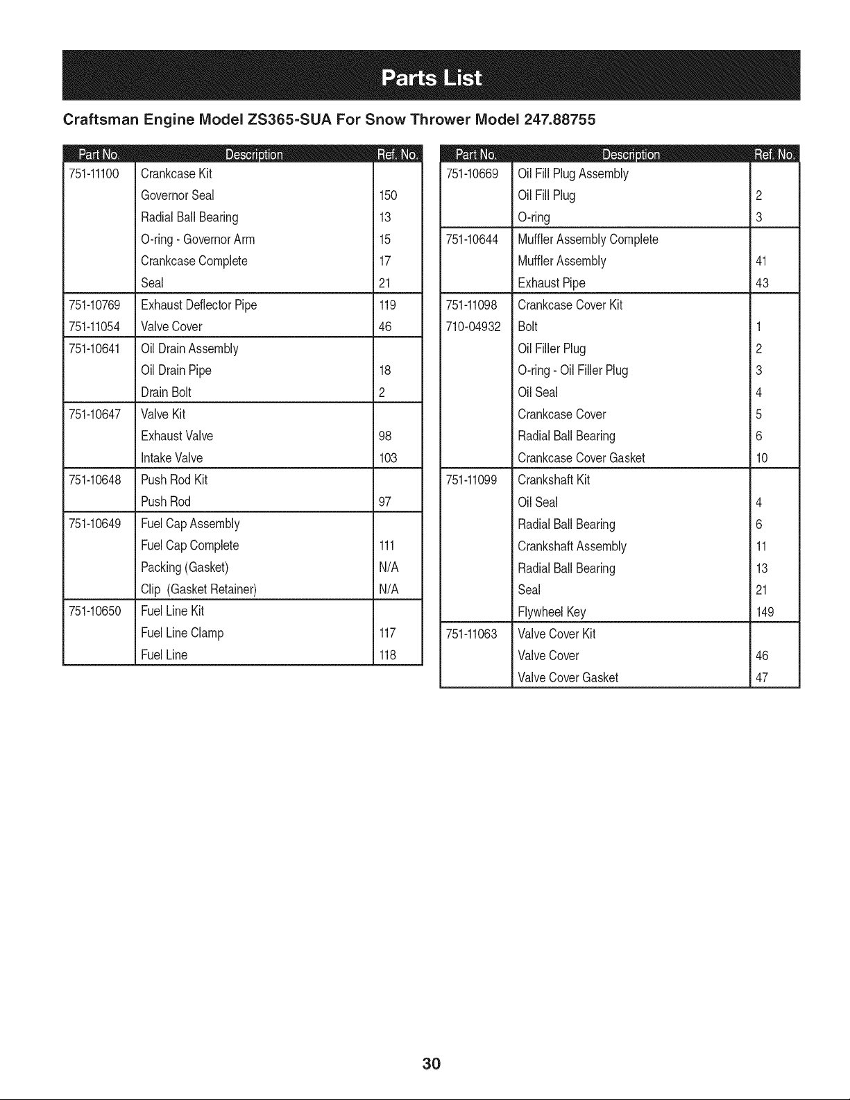
Craftsman Engine IViodel ZS365=SUA For Snow Thrower IViodel 247.88755
751-11100
751-10769
751-11054
751-10641
751-10647
751-10648
97
751-10649
751-10650
D = O 0
CrankcaseKit
GovernorSeal 150
RadialBallBearing 13
O-ring- GovernorArm 15
CrankcaseComplete 17
Seal 21
ExhaustDeflectorPipe 119
ValveCover 46
Oil DrainAssembly
Oil DrainPipe 18
DrainBolt 2
ValveKit
ExhaustValve 98
IntakeValve 103
PushRod Kit
PushRod
FuelCapAssembly
FuelCap Complete 111
Packing(Gasket) N/A
Clip (GasketRetainer) N/A
FuelLine Kit
FuelLineClamp 117
FuelLine 118
751-10669
751-10644
751-11098
710-04932
751-11099
751-11063
D = O
OilFill PlugAssembly
OilFill Plug 2
O-ring 3
MufflerAssemblyComplete
MufflerAssembly 41
ExhaustPipe 43
CrankcaseCoverKit
Bolt 1
OilFiller Plug 2
O-ring- Oil FillerPlug 3
OilSeal 4
CrankcaseCover 5
RadialBall Bearing 6
CrankcaseCoverGasket 10
CrankshaftKit
OilSeal 4
RadialBall Bearing 6
CrankshaftAssembly 11
RadialBall Bearing 13
Seal 21
FlywheelKey 149
ValveCoverKit
ValveCover 46
ValveCoverGasket 47
3O
MTD CONSUMER GROUP INC (MTD), the California Air Resources Board (CARB)
and the United States Environment Protection Agency (U. S. EPA)
Emission Control System Warranty Statement
(Owner's Defect Warranty Rights and Obligations)
EMISSIONCONTROLSYSTEMCOVERAGEIS APPLICABLETOCERTIFIEDENGINESPURCHASEDINCALIFORNIAIN2005ANDTHERE-
AFTER,WHICHARE USEDINCALIFORNIA,ANDTO CERTIFIEDMODELYEAR2005AND LATERENGINESWHICHARE PURCHASEDAND
USEDELSEWHEREIN THE UNITEDSTATES.
Californiaandelsewherein the UnitedStatesEmissionControlDefectsWarrantyCoverage
The CaliforniaAir ResourcesBoard(CARB),U. S. EPAand MTDarepleasedto explaintheemissionscontrolsystemwarrantyonyour modelyear
2006andlatersmalloff-roadengine.In California,new smalloff-roadenginesmustbe designed,builtand equippedto meet theStatesanti-smog
standards.Elsewhereinthe UnitedStates,newnon-road,spark-ignitionenginescertifiedfor model2005and later,mustmeet similarstandardsset
forthby the U. S. EPA.MTDmustwarrantythe emissioncontrolsystemon yourenginefor the periodof time listed below,providedtherehasbeen
noabuse,neglector impropermaintenanceof your smalloff-roadengine.
Youremissioncontrolsystemmayincludepartssuch as the carburetor,fuel-injectionsystem,the ignitionsystem,and catalyticconverter,fuel
tanks,fuel lines,fuel caps,valves,canisters,filters,vaporhoses,clamps,connectors,and otherassociatedemission-relatedcomponents.
Wherea warrantableconditionexists,MTDwill repairyoursmalloff-roadengineat nocost to yourincludingdiagnosis,partsand labor.
MANUFACTURER'S WARRANTY COVERAGE:
Thisemissionscontrolsystemis warrantedfor twoyears.If anyemission-relatedpart on yourengineis defective,the part will be repairedor
replacedby MTD.
OWNER'S WARRANTY RESPONSIBILITIES:
As the smalloff-roadengineowner,youare responsibleforthe performanceof the requiredmaintenancelisted in your Owner'sManual.MTD
recommendsthatyou retainall yourreceiptscoveringmaintenanceson yoursmalloff-roadengine,but MTDcan not denywarrantysolelyfor the
lackof receiptsor foryour failureto ensurethe performanceto all scheduledmaintenance.
As the smalloff-roadengineowner,youshouldhoweverbe awarethat MTDmaydenyyour warrantycoverageif yoursmall off-roadengine or part
hasfaileddue toabuse, neglect,impropermaintenanceor unapprovedmodifications.
Youare responsiblefor presentingyour smalloff-roadengineto an AuthorizedMTDServiceDealeras soonas a problemexists.Thewarranted
repairsshouldbe completedin a reasonableamountof time,notto exceed30 days.
Ifyou haveanyquestionsregardingyourwarrantyrightsand responsibilities,you shouldcontacta MTDServiceRepresentativeat 1-800-800-7310
andaddressis MTDCONSUMERGROUP,RO.Box361131,ClevelandOH,44136-0019.
DEFECTS WARRANTY REQUIREMENTS FOR 1995 AND LATER SMALL OFF-ROAD ENGINES:
Thissectionappliesto 1995andlater smalloff-roadengines.The warrantyperiodbeginson the datethe engineor equipmentis deliveredto an
ultimatepurchaser.
(a) GeneralEmissionsWarrantyCoverage
MTDmustwarrantto the ultimatepurchaserandeachsubsequentpurchaserthat the engineis:
(1)Designed,built,andequippedsoas to conformwithallapplicableregulationsadoptedby the Air ResourcesBoardpursuantto its authorityin
Chapters1and2,Part5, Division26of the HealthandSafetyCode;and
(2) Freefromdefectsin materialsandworkmanshipthat causethe failureof a warrantedpart to beidenticalin all materialrespectsto the partas
describedin theenginemanufacturer'sapplicationfor certificationfora periodof two years.
(b)The warrantyonemissions-relatedpartswill be interpretedas follows:
(1)Anywarrantedpart that is not scheduledfor replacementas requiredmaintenancein the writteninstructionsrequiredby Subsection(c)
mustbe warrantedfor the warrantyperioddefinedinSubsection(a)(2). If any such partfailsduringthe periodof warrantycoverage,it mustbe
repairedor replacedby MTDaccordingto Subsection(4) below.Anysuchpart repairedor replacedunderthewarrantymustbe warrantedfor
the remainingwarrantyperiod.
(2)Any warrantedpartthat is scheduledonlyfor regularinspectioninthe writteninstructionsrequiredby Subsection(c) must bewarrantedfor
thewarrantyperioddefinedin Subsection(a)(2).A statementinsuch writteninstructionsto the effectof "repairor replaceas necessary"will
not reducethe periodof warrantycoverage.Anysuch part repairedor replacedunderwarrantymustbe warrantedforthe remainingwarranty
period.
(3) Anywarrantedpartthat whichis scheduledfor replacementas requiredmaintenancein the writteninstructionsrequiredby Subsection(c)
mustbe warrantedfor the periodd timepriorto the first scheduledreplacementpointforthat part.Ifthe part fails priorto thefirst scheduled
replacement,the part mustbe repairedor replacedby MTDaccordingto Subsection(4) below.Any suchpart repairedor replacedunder
warrantymustbewarrantedfor the remainderof the periodpriorto the first scheduledreplacementpointfor the part.
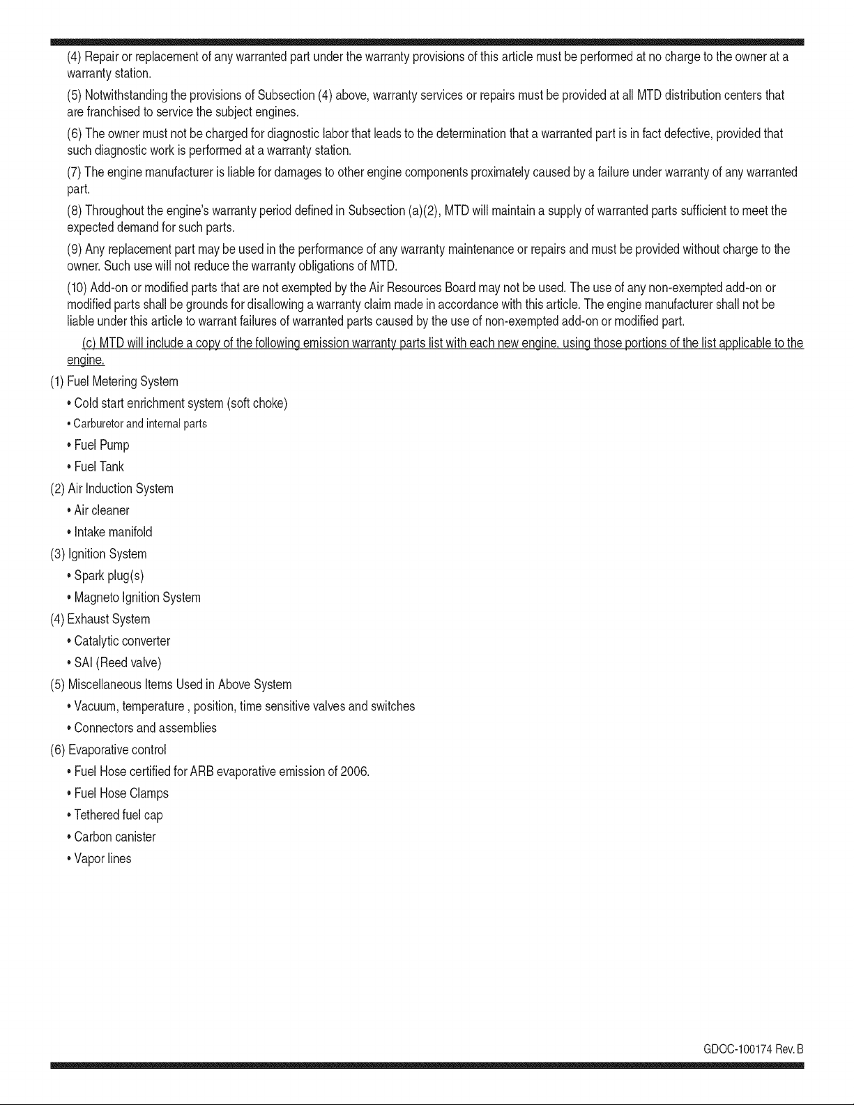
(4)Repairorreplacementofanywarrantedpartunderthewarrantyprovisionsofthisarticlemustbeperformedatnochargetotheownerata
warrantystation.
(5)NotwithstandingtheprovisionsofSubsection(4)above,warrantyservicesorrepairsmustbeprovidedatallMTDdistributioncentersthat
arefranchisedtoservicethesubjectengines.
(6)Theownermustnotbechargedfordiagnosticlaborthatleadstothedeterminationthatawarrantedpartisinfactdefective,providedthat
suchdiagnosticworkisperformedatawarrantystation.
(7)Theenginemanufacturerisliablefordamagestootherenginecomponentsproximatelycausedbyafailureunderwarrantyofanywarranted
part.
(8)Throughouttheengine'swarrantyperioddefinedinSubsection(a)(2),MTDwillmaintainasupplyofwarrantedpartssufficienttomeetthe
expecteddemandforsuchparts.
(9)Anyreplacementpartmaybeusedintheperformanceofanywarrantymaintenanceorrepairsandmustbeprovidedwithoutchargetothe
owner.SuchusewillnotreducethewarrantyobligationsofMTD.
(10)Add-onormodifiedpartsthatarenotexemptedbytheAirResourcesBoardmaynotbeused.Theuseofanynon-exemptedadd-onor
modifiedpartsshallbegroundsfordisallowingawarrantyclaimmadeinaccordancewiththisarticle.Theenginemanufacturershallnotbe
liableunderthisarticletowarrantfailuresofwarrantedpartscausedbytheuseofnon-exemptedadd-onormodifiedpart.
(c) MTDwill includea copyof the followingemissionwarrantyparts list with each newengine,usingthoseportionsof the list applicableto the
e__&gine.
(1)FuelMeteringSystem
• Coldstart enrichmentsystem(soft choke)
,,Carburetorandinternalparts
• Fuel Pump
• FuelTank
(2)Air InductionSystem
• Aircleaner
• Intakemanifold
(3) IgnitionSystem
• Sparkplug(s)
• MagnetoIgnitionSystem
(4)ExhaustSystem
Catalyticconverter
• SAI (Reedvalve)
(5) MiscellaneousItemsUsedin AboveSystem
Vacuum,temperature, position,timesensitivevalvesand switches
Connectorsandassemblies
(6) Evaporativecontrol
• Fuel Hosecertifiedfor ARBevaporativeemissionof 2006.
• Fuel HoseClamps
Tetheredfuel cap
Carboncanister
Vaporlines
GD0C-100174Rev.B
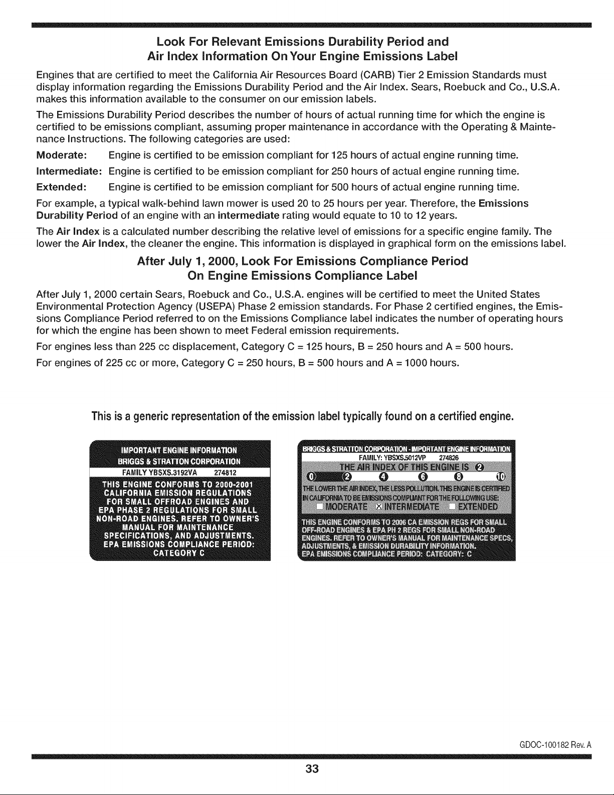
Look For Relevant Emissions Durability Period and
Air index information On Your Engine Emissions Label
Engines that are certified to meet the California Air Resources Board (CARB) Tier 2 Emission Standards must
display information regarding the Emissions Durability Period and the Air Index. Sears, Roebuck and Co., U.S.A.
makes this information available to the consumer on our emission labels.
The Emissions Durability Period describes the number of hours of actual running time for which the engine is
certified to be emissions compliant, assuming proper maintenance in accordance with the Operating & Mainte-
nance Instructions. The following categories are used:
Moderate: Engine is certified to be emission compliant for 125 hours of actual engine running time.
Intermediate: Engine is certified to be emission compliant for 250 hours of actual engine running time.
Extended: Engine is certified to be emission compliant for 500 hours of actual engine running time.
For example, a typical walk-behind lawn mower is used 20 to 25 hours per year. Therefore, the Emissions
Durability Period of an engine with an intermediate rating would equate to 10 to 12 years.
The Air Index is a calculated number describing the relative level of emissions for a specific engine family. The
lower the Air Index, the cleaner the engine. This information is displayed in graphical form on the emissions label.
After July 1,2000, Look For Emissions Compliance Period
On Engine Emissions Compliance Label
After July 1, 2000 certain Sears, Roebuck and Co., U.S.A. engines will be certified to meet the United States
Environmental Protection Agency (USEPA) Phase 2 emission standards. For Phase 2 certified engines, the Emis-
sions Compliance Period referred to on the Emissions Compliance label indicates the number of operating hours
for which the engine has been shown to meet Federal emission requirements.
For engines less than 225 cc displacement, Category C = 125 hours, B = 250 hours and A = 500 hours.
For engines of 225 cc or more, Category C = 250 hours, B = 500 hours and A = 1000 hours.
This is a generic representation of the emission label typically found on a certified engine.
FAMILYYSSXS.3192VA 274812
GDOC-100182Rev.A
33
Congratulationsonmakingasmartpurchase.YournewCraftsman@
productisdesignedandmanufacturedforyearsofdependableopera-
tion.Butlikeallproducts,itmayrequirerepairfromtimetotime.That's
whenhavingaRepairProtectionAgreementcansaveyoumoneyand
aggravation.
Here'swhattheRepairProtectionAgreement*includes:
* Expertservicebyour10,000professionalrepairspecialists
o Unlimitedserviceand no chargefor partsand laboron all
coveredrepairs
o Product replacementup to $1500if yourcoveredproductcan't be
fixed
• Discountof 10%from regularprice d serviceand relatedinstalled
partsnotcoveredby theagreement;also, 10%off regularpriceof
preventivemaintenancecheck
• Fast help by phone- we call it RapidResolution- phonesupport
froma Searsrepresentative.Thinkof usas a "talkingowner's
manual."
Onceyou purchasethe Agreement,a simplephonecall is all that it
takesfor youto scheduleservice.Youcan call anytimedayor night,or
schedulea serviceappointmentonline.
The RepairProtectionAgreementis a risk-freepurchase.If youcancel
for any reasonduringthe productwarrantyperiod,wewill provideafull
refund.Or,a proratedrefundanytimeafterthe productwarrantyperiod
expires.Purchaseyour RepairProtectionAgreementtoday!
Somelimitationsand exclusionsapply. For pricesand additional
informationin the U.S.A.call 1-800-827-6655.
*Coverage in Canadavaries on some items. Forfull details call
Sears Canadaat 1-800-361-6665.
Sears Installation Service
ForSearsprofessionalinstallationof homeappliances,garagedoor
openers,waterheaters,and othermajorhomeitems,in the U.S.A.or
Canadacall 1-800-4-MY-HOME®.
34
Declaraci6n de garantia ............................ Pagina 35
Practicas operaci6n seguras ..................... Pagina 36
Montaje ...................................................... Pagina 40
Operaci6n .................................................. Pagina 44
Servicio y Mantenimiento .......................... Pagina 48
Almacenamiento fuera de temporada ....... Pagina 53
Soluci6n de problemas .............................. Pagina 55
Etiquetas de seguridad .............................. Pagina 56
Lista de piezas ........................................... Pagina 58
Acuerdo de protecci6n para reparaciones .... Pagina 59
NOmero de servicio ................................... Cubierta posterior
CRAFTSMAN GARANTIA LIMITADA
Dos A_os en Lanzador de Nieve
Cuandohechofuncionary mantenidosegOntodas las instruccionessuministradas,si este lanzadorde nievefalladebidoa un defectoen materialo habilidadden-
tro de dos a_osde la fechao compra,vueltaestoa algunoautoriz6Craftsmanposici6ndebajada parareparaci6nlibre.Parala posici6nautorizadamAscercana,
Ilamar1-800-4MYHOME.
Esta garanfiasolicitas61o90 d[asde lafechade lacomprasi este lanzadorde nievees usadoalgunavezpara objetivosde alquilero publicidad.
Esta garanfiacubreSOLOdefectosen materialy habilidad.Chamuscano pagarApara:
• Los arficulosprescindiblesquese hacen Ilevadospuestosduranteel uso normal,incluso,perono limitadosparapatinarzapatos,platode afeitado,
esquilanalfileres,buj[a,filtro deaire,cinturones,y filtrodel aceite.
• Revisi6nde mantenimientoest_ndar,cambiosde aceite,o puestasa punto.
• Reemplazodeneum_ticoo reparaci6ncausadaporpinchazosdesdefuerade objetos,comou_as,espinas,tocones,o cristal.
• Neum_ticoo reemplazoderuedao reparaci6nqueresultade ropanormal,accidente,u operaci6nimpropiao mantenimiento.
• Las reparacionesnecesariasdebidoal abusode operador,inclusopero no limitadoparada_arcausadoafectandoobjetosquedoblanel marcoo el
cigQe6al,o el sobreexcesode velocidaddel motor.
,, Reparacionesnecesariasdebidoa negligenciade operador,inclusoperono limitadocon,da_oelectricoy mecanicocausadoporalmacenajeimpropio,
fracasode usar elgradoapropiadoy cantidadde petr61eode motor,o fracaso de mantenerel equiposegQnlasinstruccionescontenidasenel manual
del operador.
• Motor(sistemade combustible)la limpiezao lasreparacionescausadaspot el combustibledeterminaronde set contaminadasu oxidado(sevuelven
duro).En general,el combustibledeber[aser usado30 d[asdespuesde su fechade compra.
• Elempejoramientonormaly la ropa de losfines exteriores,o productoetiquetanel reemplazo.
Esta garanfiaseaplica s61omientrasesteproductoes dentrode losEstadosUnidos.
Esta garanfialeda derechoslegalesespec[ficos,y ustedtambienpuedetenet otrosderechosquevat[an de estadoal estado.
Sears, Roebuck and Co., Hoffman Estates, IL 60179
Tipode aceite del motor:
Capacidadde aceitedel motor:
Capacidadde combustible:
Buj[as:
Separaci6nde las buj[as:
5W-30
20 onzas
2.3 cuartos
Torch F6RTC (F6TC)
.020" to .030"
N_mero de modelo ..........................................................
N_mero de serie ..............................................................
Fechade compra .............................................................
Registrearribael nOmerodel modelo,el nOmerode seriey la fecha
de compra
© Sears Brands,LLC
35
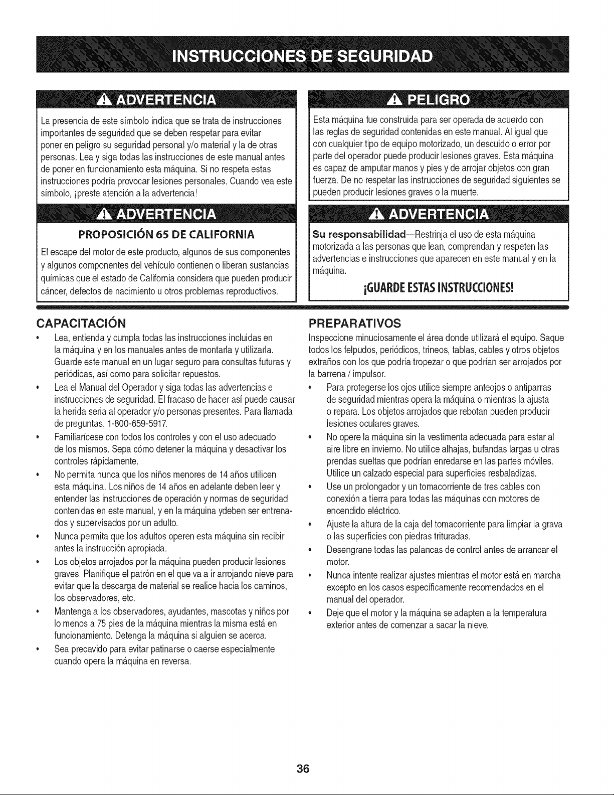
Lapresenciade este sirnboloindicaque setrata de instrucciones
irnportantesde seguridadque se deben respetarpara evitar
ponerenpeligrosu seguridadpersonaly/o materialy lade otras
personas.Lea y sigatodaslasinstruccionesde este manualantes
de poneren funcionarnientoestarn_.quina.Si no respetaestas
instruccionespodria provocarlesionespersonales.Cuandoveaeste
sirnbolo,ipresteatenci6na la advertencia!
PROPOSICI6N 65 DE CALIFORNIA
Elescapedel motorde este producto,algunosde sus cornponentes
y algunoscornponentesdelvehiculocontieneno liberansustancias
quirnicasqueelestadode Californiaconsideraque puedenproducir
c_.ncer,defectosde nacirnientouotrosproblernasreproductivos.
Estarn_.quinarueconstruidaparaseroperadadeacuerdocon
las reglasde seguridadcontenidasen este manual.AI igualque
concualquiertipo de equipo rnotorizado,undescuidoo error por
partedel operadorpuedeproducirlesionesgraves.Estarn_.quina
es capazde arnputarrnanosy piesy dearrojarobjetoscon gran
fuerza.De no respetarlas instruccionesde seguridadsiguientesse
puedenproducirlesionesgraveso la rnuerte.
Su responsabilidad--Restrinja el usode estarn_.quina
rnotorizadaalas personasque lean,cornprendany respetenlas
advertenciase instruccionesqueapareceneneste manualyen la
rn_.quina.
iGUARDEESTASINSTRUCCIONES!
CAPACITACION
• Lea,entienday curnplatodaslas instruccionesincluidasen
la rn_.quinayen los rnanualesantesde rnontarlay utilizarla.
Guardeestemanualen un lugarseguropara consultasfuturasy
peri6dicas,asi cornoparasolicitarrepuestos.
• Leael ManualdelOperadory sigatodas las advertenciase
instruccionesdeseguridad.El fracasode hacerasi puedecausar
la heridaseriaal operadory/o personaspresentes.ParaIlarnada
de preguntas,1-800-659-5917.
• Farniliaricesecontodos los controlesy con el usoadecuado
de losrnisrnos.Sepac6rnodetenerlarn_.quinay desactivarlos
controlesr_.pidarnente.
• No perrnitanuncaque losni_os rnenoresde 14a_osutilicen
estarn_.quina.Los ni_osde 14a_osen adelantedebenleery
entenderlas instruccionesde operaci6ny norrnasdeseguridad
contenidasen estemanual,y en la rn_.quinaydebenserentrena-
dosy supervisadospor unadulto.
• Nuncaperrnitaquelos adultosoperenestarn_.quinasin recibir
antesla instrucci6napropiada.
• Losobjetosarrojadosporla rn_.quinapuedenproducirlesiones
graves.Planifiqueel patr6nen el queva air arrojandonievepara
evitarquela descargade materialse realicehacialos carninos,
los observadores,etc.
• Mantengaa los observadores,ayudantes,rnascotasy ni_ospor
Io rnenosa 75 piesde larn_.quinarnientrasla rnisrnaest,.en
funcionarniento.Detengala rn_.quinasialguiense acerca.
• Seaprecavidopara evitarpatinarseo caerseespecialrnente
cuandoopera la rn_.quinaen reversa.
PREPARATIVOS
Inspeccionerninuciosarnenteel _.readondeutilizar_,el equipo.Saque
todoslos felpudos,peri6dicos,trineos,tablas,cables y otrosobjetos
extra_oscon los quepodriatropezaro que podrianser arrojadospor
la barrena/ irnpulsor.
• Paraprotegerselosojos utilice siernpreanteojoso antiparras
de seguridadrnientrasoperala rn_.quinao rnientrasla ajusta
o repara.Losobjetosarrojadosquerebotanpuedenproducir
lesionesocularesgraves.
• Nooperela rn_.quinasin la vestirnentaadecuadaparaestaral
aire libreen invierno.No utilicealhajas,bufandaslargasu otras
prendassueltasquepodrianenredarseenlas partesrn6viles.
Utiliceun calzadoespecialpara superficiesresbaladizas.
• Useun prolongadory untornacorrientede tres cablescon
conexi6natierra paratodas las rn_.quinascon rnotoresde
encendidoel_ctrico.
• Ajustela alturade lacaja deltornacorrientepara lirnpiarla grava
o las superficiescon piedrastrituradas.
• Desengranetodas las palancasde controlantesde arrancarel
motor.
• Nuncaintenterealizarajustesrnientrasel motorest,.enrnarcha
exceptoen los casosespedficarnenterecornendadosenel
manualdel operador.
• Dejequeel motory la rn_.quinaseadaptena laternperatura
exteriorantesdecornenzara sacarla nieve.
36

Manejo seguro de la gasolina
Paraevitarlesionespersonaleso daSosmaterialestengamucho
cuidadocuandotrabajecon gasolina.La gasolinaes sumamente
infiamabley sus vaporespuedencausarexplosiones,Si se derrama
gasolinaencimao sobrela ropase puedelesionargravementeya que
se puedeincendiar,L&vesela piel y c&mbiesede ropade inmediato,
• Utilices61olos recipientesparagasolinaautorizados.
• Apaguetodoslos cigarrillos,cigarros,pipasy otras fuentesde
combusti6n.
• Nuncacarguecombustibleen la m_.quinaen unespado cerrado,
• Nuncasaquelatapa del combustibleni agreguecombustible
mientrasel motorest&calienteo en marcha.
• Dejequeel motorse enfriepor Iomenosdos minutosantesde
volvera cargarcombustible,
• NuncaIleneenexcesoel dep6sitode combustible.Lleneel
tanquea no m_.sde 1/2pulgadapordebajode la basedelcuello
deIlenadodejandoespaciopara la dilataddn del combustible,
• Vuelvaa colocarla tapade lagasolinay ajQstelabien,
• Limpieelcombustiblequese hayaderramadosobreel motory el
equipo.Trasladela m_.quinaa otra zona, Espere5 minutosantes
deencenderel motor,
• Nuncaalmacenela m_.quinao el redpientede combustibleen
unespaciocerradodonde hayafuego,chispaso luz piloto(por
ejemplo,hornos,calentadoresde agua,calefactores,secadores
de ropa,etc.),
Dejeque la m&quinase enfrieporIo menos5 minutosantesde
guardarla,
• NuncaIlenelos recipientesenel interiorde unvehiculoo camidn
o cajade remolquecon recubrimientospl&sficos.Coloque
siemprelos redpientesen el pisoy lejosdelvehiculoantesde
Ilenarlos.
• Sies posiNe,retireel equipoa gasolinadelcami6no remolque
y II_neloen el suelo,Si esto no es posiNe,Ileneel equipoen un
remolqueconcontenedorport_.til,en vezdedesdeuna boquilla
dispensadoradegasolina.
• Mantengala boquilladispensadoraen contactocon el hordedel
depdsitode combustibleo con la aberturadel recipienteen todo
momento,hastaterminarlacarga.No utiliceun disposifivode
apertura/derrede boquilh,
FUNCIONAMIENTO
• No pongalas manoso los piescercade las piezas rotatorias,
enla cajade la barrena/ impulsoro en el montajedel canalde
descarga,Hacercontactocon piezasgiratoriaspuederesultaren
la amputacidndemanoso pies.
• La palancade controlde la barrena/ impulsores un disposifivo
deseguridad,Nuncaevitesu funcionamiento,De hacerlola
operad6ndela m_.quinaes riesgosay puedeocasionarlesiones,
• Las palancasde control debenfuncionarbienen ambasdirec-
clonesy regresarautom_.ticamentea la posicidnde desengrane
cuandose las suelta,
Nuncaoperela m_.quinasi falta un montajedelcanalo si el
mismoest,.da_ado.Mantengatodos losdispositivosde seguri-
daden su lugaryen funcionamiento.
• Nuncaenciendael motoren espacioscerradosoen una zona
con pocaventilaci6n.Elescapedel motorcontienemon6xidode
carbono,ungas inodoroy letal.
• Noutilicela m_.quinabajola influenciadel alcoholo las drogas.
• El silenciadory el motorse calientany puedencausarquemadu-
ras.Nolos toque. Mantengaa los ni_osalejados.
• Seasumamenteprecavidocuandooperelam_.quinasobreuna
superficiecon gravao cuandola cruce.Mant_ngasealerta por si
sepresentanpeligrosocultoso tr_.nsito.
• Tengacuidadocuandocambiede direcci6no cuandooperela
m_.quinaen pendientes.
• Planifiqueel patr6nen elqueva air arrojandonieveparaevitar
que ladescargadematerialse produzcahacialas ventanas,
lasparedes,losautom6viles,etc.y evitarasi posiblesda_os
materialeso lesionesproducidaspor los rebotes.
• Nuncadirija ladescargahacialos ni_os,los observadoreso las
mascotasni dejequenadiese paredelantede lam_.quina.
• Nosobrecarguelacapacidadde la m_.quinatratandode sacarla
nievemuyr_.pidamente.
• Nuncaopere esta m_.quinasin buenavisibilidado iluminaci6n.
Siempredebe estar segurode queest,.bienafirmadoy su-
jetandofirmementelasmanijas.Camine,nuncacorra.
• Cortela corrientea la barrena/ impulsorcuandotransportela
m_.quinao cuandola mismanoest,. en uso.
• Nuncaopere la m_.quinaa alta velocidadde desplazamiento
sobresuperficiesresbaladizas.Mirehaciaabajoy haciaatr_.sy
tengacuidadocuandovaya marchaatr_.s.
• Si la m_.quinacomenzaraa vibrarde maneraanormal,detengael
motor,desconecteel cablede la bujiay p6ngalade maneraque
hagamasacontrael motor.Inspeccionela m_.quinaminuciosa-
menteparavet si est,.da_ada.Reparetodos los da_osantesde
encendery operarla m_.quina.
• Desengranetodaslas palancasde controly detengael motor
antesdedejarla posici6nde operaci6n(detr_.sde las manijas).
Esperea quela barrena/ impulsorse detengaporcompleto
antesdedestaparel montajedel canalo realizarajustese
inspecciones.
• Nuncapongalas manosen lasaberturasde descargao de
recolecci6n.Utilicesiemprela herramientade limpiezaque se
adjuntaparadestaparla aberturadedescarga.Nodestapeel
montajedelcanal mientrasel motorest,.en funcionamiento.
Antesdedestaparlo,apagueel motory permanezcadetr_.sde las
manijashastaquetodaslas partes m6vilesse hayandetenido.
• Uses61ounionesy accesoriosaprobadospor el fabricante(por
ejemplo,pesasparalas ruedas,cadenaspara los neum_.ticos,
cabinas,etc.).
37
• Paraencenderel motor,jab de lacuerdalentarnentehastaque
sientaresistencb, luegojab r_.pidarnente.Elreplieguer_.pidode
lacuerdade arranque(tensbn de retroceso)lejalar_,la rnanoy
el brazohaciaelmotorrn_.sr_.pidode Io que ustedpuede soltar.
El resultadopuedenserhuesosrobs, fracturas,hernatornaso
esguinces.
• Si se presentansituacionesque no est&nprevistasen este
manual,seacuidadosoy useel sentidocornQn.P6ngaseen
contactocon Asistenciaal Clientepara solicitarayuday el
nornbredeldistribuidorde serviciorn_.scercano.
MANTENIMIENTO Y ALMACENAMIENTO
Nuncaalterelos dispositivosde seguridad.Controleperi6dica-
rnentequefuncionencorrectarnente.Rernitasealas secciones
de rnantenirnientoy ajustede este manual.
• Antesde realizarla lirnpieza,repararo revisarla rn_.quina,
desengranetodaslas palancasdecontroly detengael motor.
Esperea quela barrena/ irnpulsorsedetengapor cornpleto.
Desconecteel cable de la bujiay p6ngalohaciendornasacontra
el motorparaevitarquese enciendaaccidentalrnente.
Controlefrecuenternentequetodoslospernosy tornillosest_n
bienajustadosparacornprobarquela rn_.quinase encuentra
encondicionessegurasde funcionarniento.Adern_.s,hagauna
inspecci6nvisualde larn_.quinaparaverificarsi est,.daSada.
• Nocarnbiela configuraci6ndel reguladordel motorni acelere
dernasiadoel rnisrno.El reguladordelmotorcontrolala veloddad
rn_.xirnasegurade funcionarnientodel motor.
• Las placasde raspadoy las zapatasantideslizantesque se
usancon la rn_.quinaquitanievese desgastany se daSan.
Paraprotegersuseguridad,verifiquefrecuenternentetodos los
cornponentesy reernpl&celoss61ocon partesde losfabricantes
deequiposoriginales(OEM)."iEI usode piezasquenocurnplen
con lasespecificacionesdelequipooriginalpuederesultaren
rendirnientoinadecuadoadern_.sde poneren riesgola seguri-
dad!"
Reviselas palancasde controlperi6dicarnentepara verificar
queengraneny desengranenadecuadarnentey ajOstelossi es
necesario.Consultela secci6nde ajustesde estemanualdel
operadorparaobtenerinstrucciones.
Mantengao reernplacelasetiquetasde seguridade instrucciones
segOnseanecesario.
Respetelas norrnasreferentesa ladisposici6ncorrectay las
reglarnentacionessobregasolina,aceite,etc. para protegerel
medicarnbiente.
Antesde alrnacenarlarn_.quinaenci_ndalaunosrninutospara
sacarlanieveque hayaquedadoen la rnisrnay para evitarasi
quese congelela barrena/ irnpulsor.
• SegOnla Cornisi6nde Seguridadde Productosparael Consu-
rnidorde los EstadosUnidos(CPSC)y la Agenciade Protecci6n
Arnbientalde los EstadosUnidos(EPA),esteproductotieneuna
vida Qtilmediade siete(7)a_os,6 60 horasdefuncionarniento.
AI finalizarla vidaOtilmedia,adquieraunarn_.quinanuevao
hagainspeccionaranualrnente_stapor undistribuidorde servicio
autorizadoparacerciorarsede que todoslos sisternasrnec_.nicos
y deseguridadfuncionancorrectarnentey notienenexcesivo
desgaste.SinoIo hace, puedenproducirseaccidentes,lesiones
o rnuerte
• Nuncaalrnacenela rn_.quinao el recipientede combustibleen un
espaciocerradodonde hayafuego,chispaso luz pilotocornopor
ejernplo,calentadoresde agua,hornos,secadoresde ropa,etc.
• Consultesiernpreel manualdeloperadorparaobtener
instruccionesadecuadaspara el almacenarnientofuerade
ternporadaVerifiquefrecuenternentelalinea de combustible,el
tanque,el tap6n,y losaccesoriosbuscandorajaduraso perdidas.
Reernplacede ser necesario.
• Nod_ arranqueal motorsi no est,.labujiade encendido.
NO MODIFIQUE EL MOTOR
Paraevitarlesionesgraveso larnuerte,nornodifiqueel motorbajo
ningunacircunstancia.Si carnbialaconfiguraci6ndel reguladorel
motorpuededescontrolarsey operara velocidadesinseguras.Nunca
carnbiela configuraci6ndef_.bricadel reguladordelmotor.
AVISO REFERIDO A EIVlISIONES
Losrnotoresque est_.ncertificadosy curnplencon las regulaciones
de ernisionesfederalesEPAy de CaliforniaparaSORE(Equipos
peque_ostodoterreno)est_.ncertificadosparaoperarcongasolina
cornQnsin plornoy puedenincluirlos siguientessisternasde control
de ernisiones:Modificaci6nde motor(EM) y catalizadorde tresvbs
(TWO)siest_.nequipadosde esa rnanera.
GUARDACHISPAS
Estarn_.quinaest,.equipadacon unmotorde cornbusti6ninternay
nodebeser utilizadaen o cercade unterrenoagrestecubiertopor
bosque,rnalezaso hierbaexceptosi el sisternade escapedelmotor
est,.equipadocon un arnortiguadordechispasquecurnplacon las
byes localeso estatalescorrespondientes,encasode haberlas.
Si se utilizaunarnortiguadorde chispasel operadorIo debe rnantener
en condicionesde usoadecuadas.Enel Estadode Californialas
rnedidasanteriorrnenternencionadassonexigidasporIcy (Arficulo
4442del C6digode RecursosPOblicosde California).Esposible
queexistanbyes sirnilaresenotrosestados.Lasbyes federalesse
aplicanen territoriosfederales.
Puedeconseguirelarnortiguadorde chispasparael silenciadora
travesde su distribuidorautorizadode rnotoreso poni_ndoseen
contactoconel departarnentode servicios.
38
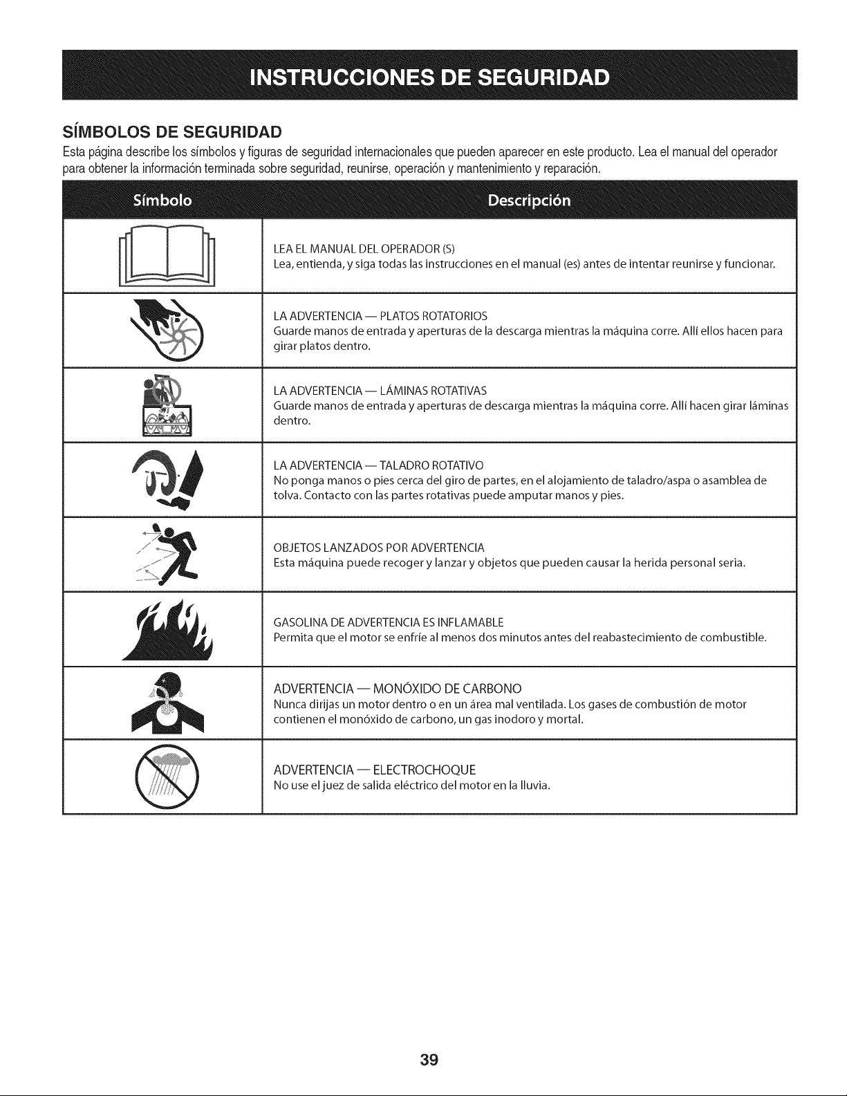
SilVIBOLOS DE SEGURIDAD
Estap_ginadescribelos simbolosy figurasde seguridadinternacionalesquepuedenaparecereneste producto.Leael manualdeloperador
_araobtenerla informaci6nterminadasobreseguridad,reunirse,operaci6ny mantenimientoy reparaci6n.
&
LEA EL MANUAL DEL OPERADOR (S)
Lea, entienda, y siga todas las instrucciones en el manual (es) antes de intentar reunirse y funcionar.
LA ADVERTENCIA -- PLATOS ROTATORIOS
Guarde manos de entrada y aperturas de la descarga mientras la m_iquina corre. Alli ellos hacen para
girar platos dentro.
LA ADVERTENCIA- LAMINAS ROTATIVAS
Guarde manos de entrada y aperturas de descarga mientras la m_iquina corre. Alli hacen girar I_iminas
dentro.
LA ADVERTENCIA -- TALADRO ROTATIVO
No ponga manos o pies cerca del giro de partes, en el alojamiento de taladro/aspa o asamblea de
tolva. Contacto con las partes rotativas puede amputar manos y pies.
OBJETOS LANZADOS POR ADVERTENClA
Esta m_iquina puede recoger y lanzar y objetos que pueden causar la herida personal seria.
GASOLINA DE ADVERTENCIA ESINFLAMABLE
Permita que el motor se enfrie al menos dos minutos antes del reabastecimiento de combustible.
ADVERTENCIA -- MONOXIDO DE CARBONO
Nunca dirijas un motor dentro o en un _irea mal ventilada. Los gases de combusti6n de motor
contienen el mon6xido de carbono, un gas inodoro y mortal.
ADVERTENCIA -- ELECTROCHOQUE
No use el juez de salida el_ctrico del motor en la Iluvia.
39
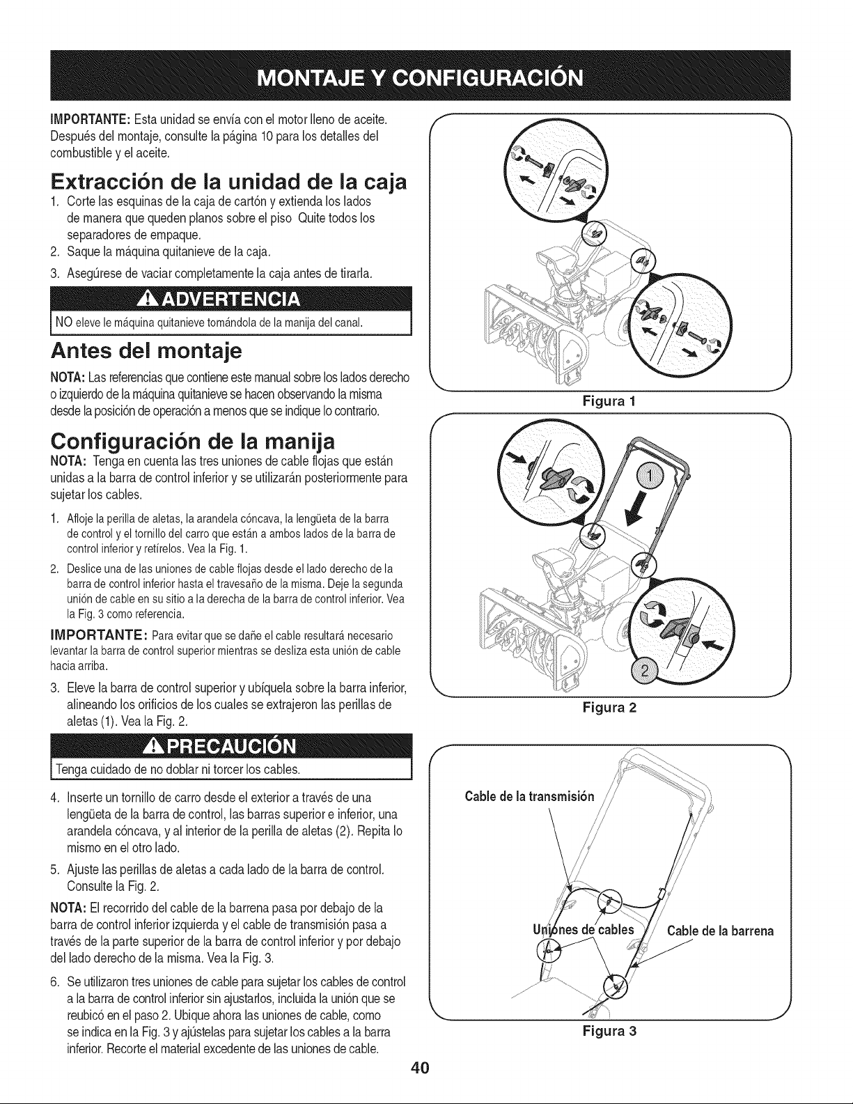
IMPORTANTE:Esta unidadse enviaconel motorIlenode aceite,
Despu_sdelrnontaje,consultela p_.gina10 para losdetallesdel
combustibley elaceite,
Extracci6n de la unidad de la caja
1, Corte lasesquinasdela cajade cart6ny extiendaloslados
de rnaneraque quedenpianossobreel piso Quitetodos los
separadoresde ernpaque,
2, Saquela rn_.quinaquitanievede lacaja,
3, AsegQresede vaciarcompletarnentela cajaantes de tirarla,
NO elevele mAquinaquitanievetomAndolade la manijadel canal.
Antes del montaje
NOTA:Lasreferenciasque contieneestemanualsobrelosladosderecho
oizquierdodelarn_.quinaquitanievesehacenobservandola rnisrna
desdelaposici6ndeoperaci6na rnenosqueseindiqueIocontrario,
Configuraci6n de la manija
NOTA: Tengaen cuentalas tresunionesdecable flojasque est_.n
unidasa labarradecontrolinferiory se utilizarAnposteriorrnentepara
sujetarlos cables,
1. Afiojela perillade aletas,la arandelac6ncava,la leng0etade la barra
de control y eltornillodel carroqueestAna ambos ladosde la barrade
control inferiory refirelos.Veala Fig. 1.
2. Desliceunade lasunionesde cablefiojasdesde el ladoderechode la
barrade controlinferiorhasta eltravesa5ode la misma.Dejela segunda
uni6nde cable ensu sitioa laderecha de la barrade control inferior.Vea
la Fig.3 como referencia.
IIVIPORTANTE: Paraevitarque se da5e el cableresultar_necesario
levantarlabarra de control superiormientrasse deslizaesta uni6nde cable
haciaarriba.
3, Elevelabarra de controlsuperiory ubiquelasobre[abarrainferior,
alineandolos orificiosde los cualesse extrajeronlas perillasde
aletas(1), Veala Fig,2,
Figura 1
Figura 2
J
J
Tengacuidadode no doblarni torcerlos cables.
. Inserteuntornillodecarrodesdeel exterioratravesde una
leng_Jetade labarradecontrol,lasbarrassuperiore inferior,una
arandelac6ncava,y al interiorde laperilladealetas(2). RepitaIo
rnisrnoen el otrolado.
5. Ajustelas perillasde aletasa cadaladode la barrade control.
Consultela Fig.2.
NOTA: El recorridodel cablede labarrenapasapor debajo de la
barrade controlinferiorizquierday el cablede transrnisi6npasaa
travesde la partesuperiorde la barra de controlinferiory por debajo
delladoderechode la rnisrna.Vea la Fig.3.
.
Seutilizarontresunionesde cableparasujetarlos canes de control
a la barradecontrolinferiorsinajustarlos,incluidalauni6nque se
reubic6enelpaso2. Ubiqueahoralas unionesde cable,corno
se indicaenla Fig.3 y ajQstelasparasujetarloscablesa labarra
inferior.Recorteelmaterialexcedentede las unionesdecable.
f
Cable de la transmisi6n /
CaMede [a barrena
Figura 3
4O
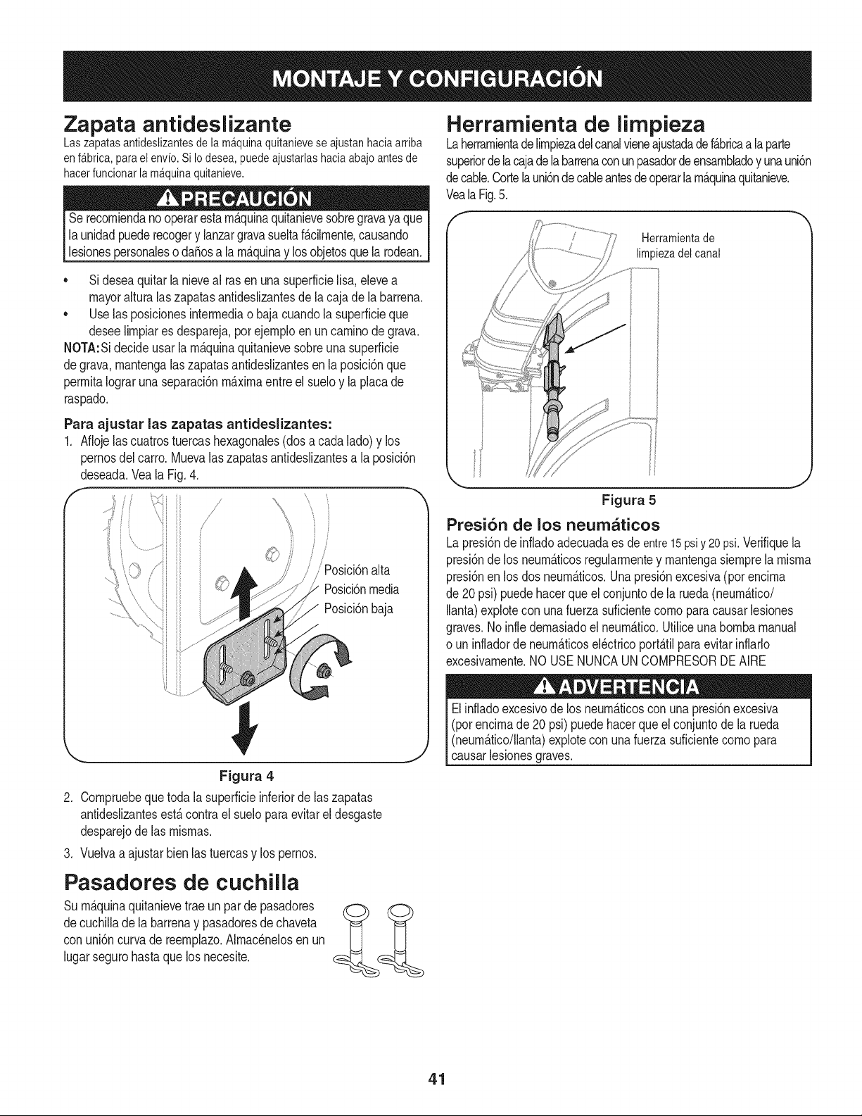
Zapata antideslizante
Laszapatasantideslizantesdelam_quinaquitanieveseajustanhaciaarriba
enf_brica,parael envfo.SiIodesea,puedeajustarlashaciaabajoantesde
hacerfuncionarla m_quinaquitanieve.
Serecorniendano operarestarn_.quinaquitanievesobregravaya que
launidadpuederecogery lanzargravasueltaf_.cilrnente,causando
lesionespersonaleso da_osa larn_.quinay losobjetosquelarodean.
• Sideseaquitarla nieveal rasen unasuperficielisa,elevea
mayoralturalaszapatasantideslizantesde la cajade la barrena.
• Uselas posicionesinterrnediao baja cuandola superficieque
deseeNrnpiares despareja,porejernploenun carninodegrava.
NOTA:Sidecideusarla rn_.quinaquitanievesobreuna superficie
degrava,rnantengalas zapatasantidesNzantesen laposici6nque
perrnitaIograrunaseparaci6nrn_.xirnaentreel sueloy la placade
raspado.
Para ajustar las zapatas antideslizantes:
1. Aflojelascuatrostuercashexagonales(dos a cadalado)y los
pernosdel carro.Muevalas zapatasantideslizantesa la posici6n
deseada.Veala Fig.4.
f
s/l/ _
/ i i
Posici6nalta
Posici6nmedia
Posici6nbaja
Figura 4
2. Cornpruebequetoda la superficieinferiorde laszapatas
antideslizantesest,. contrael sueloparaevitar el desgaste
desparejode las rnisrnas.
3. Vuelvaa ajustarbienlas tuercasy los pernos.
Pasadores de cuchilla
Surn_.quinaquitanievetraeun parde pasadores
decuchillade la barrenay pasadoresde chaveta
con uni6ncurva de reernplazo.Alrnacenelosen un
lugarsegurohastaque losnecesite.
Herrarnienta de limpieza
Laherrarnientadelirnpiezadelcanalvieneajustadadef_.bricaa la parte
superiorde lacajadelabarrenaconunpasadordeensarnbladoy unauni6n
decable.Cortelauni6ndecableantesde operarla rn_.quinaquitanieve.
VealaFig.5.
f
Herramientade
limpiezadel canal
J
Figura 5
Presi6n de los neum_ticos
Lapresi6nde infladoadecuadaes de entre15psiy 20psi.Verifiquela
presi6ndelos neurn_.ticosregularrnentey rnantengasiernprela rnisrna
presi6nenlos dos neurn_.ticos.Unapresi6nexcesiva(por encirna
de 20psi) puedehacerque el conjuntode la rueda(neurn_.tico/
Ilanta)explotecon unafuerzasuficientecornoparacausar lesiones
graves.Noinfle dernasiadoel neurn_.tico.UtiNceunabornbamanual
o un infladorde neurn_.ticosel_ctricoport_.tilparaevitarinflarlo
excesivarnente.NO USENUNCAUNCOMPRESORDEAIRE
Elinfladoexcesivode los neurn_.ticoscon una presi6nexcesiva
(pot encirnade 20 psi)puede hacerqueel conjuntode la rueda
(neurn_.tico/Nanta)explorecon una fuerzasuficientecornopara
causarlesionesgraves.
41
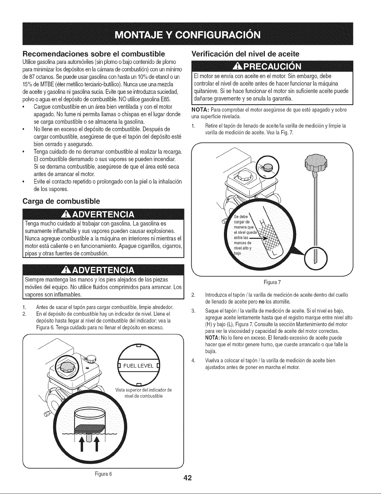
Recomendaciones sobre el combustible
Utilicegasolinaparaautorn6viles(sinplornoo bajocontenidodeplorno
pararninirnizarlosdep6sitosenlac_rnaradecornbusti6n)con unrninirno
de87octanos.Sepuedeusargasolinaconhastaun 10%deetanolo un
15%de MTBE(eterrnetilicoterciario-bufilico).Nuncauseunarnezcla
deaceitey gasolinani gasolinasucia.Eviteque seintroduzcasuciedad,
polvooaguaenel dep6sitode combustible.NOutilicegasolinaE85.
* Carguecombustibleenun _reabien ventiladay conel motor
apagado.Nofumeni perrnitallamasochispasenel lugardonde
se cargacombustibleo se alrnacenalagasolina.
* No Ileneen excesoel dep6sitode combustible.Despu_sde
cargarcombustible,asegQresedeque eltap6ndel dep6sitoest_
biencerradoy asegurado.
* Tengacuidadode no derrarnarcombustibleal realizarla recarga.
Elcombustiblederrarnadoo sus vaporesse puedenincendiar.
Si sederrarnacombustible,asegQresede que el _rea est_ seca
antesde arrancarel motor.
. Eviteel contactorepetidoo prolongadocon la pielo la inhalaci6n
de losvapores.
Carga de combustible
Tengarnuchocuidadoal trabajarcon gasolina.La gasolinaes
surnarnenteinfiarnabley susvaporespuedencausarexplosiones.
Nuncaagreguecombustiblea la rn&quinaen interioresni rnientrasel
motorest&calienteoen funcionarniento.Apaguecigarrillos,cigarros,
pipasy otras fuentesdecornbusti6n.
Verificaci6n del nivel de aceite
Elmotorse enviacon aceiteenel motor.Sinembargo,debe
controlarelnivelde aceiteantesdehacerfuncionarla rn_.quina
quitanieve.Si se hacefuncionarel motorsin suficienteaceitepuede
da_arsegravernentey seanulala garanfia.
NOTA: Paracomprobarel motorasegOresede que esteapagadoy sobre
una superficienivelada.
1. Retireel tap6nde Ilenadode aceite/lavarilla de medici6ny limpiela
varilla de medici6nde aceite.Veala Fig.7.
Siernprernantengalas rnanosy los piesalejadosde las piezas
rn6vilesdelequipo.No utilicefiuidoscornprirnidosparaarrancar.Los
vaporesson inflarnables.
1,
2.
Antesde sacar eltap6n paracargar combustible,limpie alrededor.
En el dep6sitode combustiblehay un indicadorde nivel. Lleneel
dep6sitohastaIlegaral nivelde combustibledel indicador;vea la
Figura6. Tengacuidado para no Ilenarel dep6sitoen exceso.
Vista superior del indicadorde
nivel de combustible
1
Figura7
2. Introduzcael tap6n /la varilla de medici6nde aceitedentrodel cuello
de Ilenadode aceite pero no losatornille.
3. Saqueeltap6n /la varilla de medici6nde aceite.Si el niveles bajo,
agregueaceitelentamentehastaque el registromarqueentre nivelalto
(H)y bajo(L), Figura7.Consultela secci6n Mantenimientodel motor
paraver laviscosidadycapacidadde aceitedel motorcorrectas.
NOTA:No IoIleneen exceso. ElIlenadoexcesivodeaceite puede
hacerque el motorgenere humo,quecuestearrancarloo quefalle la
bujia.
4. Vuelvaa colocarel tap6n/la varilla de medici6nde aceitebien
ajustadosantes de poneren marchael motor.
J
Figura6 42
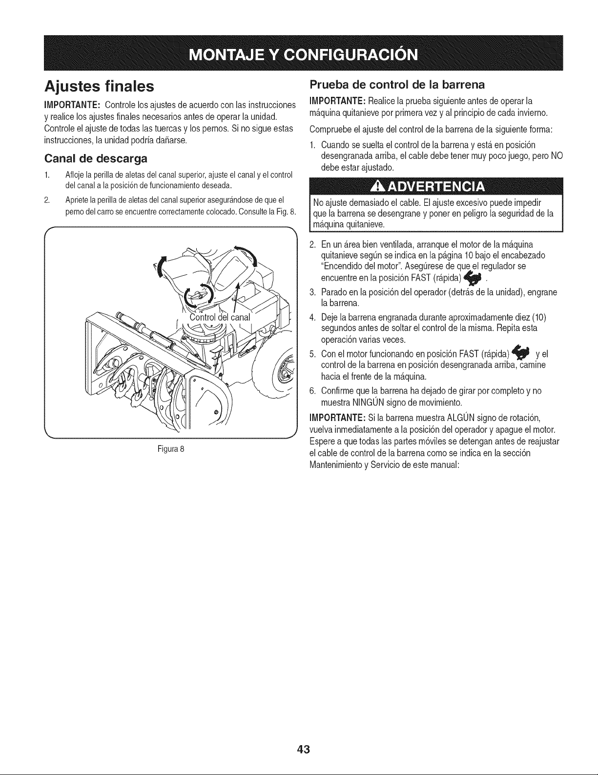
Ajustes finales
IMPORTANTE:Controlelosajustesdeacuerdocon las instrucciones
y realicelos ajustesfinalesnecesariosantesde operarla unidad.
Controleel ajustede todaslas tuercasy los pernos.Sino sigueestas
instrucciones,la unidadpodriadaSarse.
Canal de descarga
1. Aflojela perilladealetasdelcanalsuperior,ajusteelcanaly elcontrol
delcanala la posici6ndefuncionamientodeseada.
2. Aprietela perilladealetasdelcanalsuperiorasegur_ndosedequeel
pernodelcarroseencuentrecorrectamentecolocado.Consultela Fig.8.
Figura8
Prueba de control de la barrena
IMPORTANTE:Realicela pruebasiguienteantesdeoperarla
m_.quinaquitanieveporprimeravezy al principiodecada invierno.
Compruebeel ajustedelcontrolde la barrenade la siguienteforma:
1. Cuandose sueltael control de la barrenay estAenposici6n
desengranadaarriba,el cabledebe tenermuypocojuego,peroNO
debeestarajustado.
Noajustedemasiadoel cable.Elajusteexcesivopuedeimpedir
quela barrenasedesengraney porteren peligrola seguridadde la
m_.quinaquitanieve.
.
4.
Enun_.reabien ventilada,arranqueelmotorde la m_.quina
quitanievesegQnse indicaenla p_.gina10bajo el encabezado
"Encendidodelmotor".AsegQresedequeel reguladorse
encuentreen la posici6nFAST(r_.pida)
M
Paradoen la posici6ndel operador(detr_.sdela unidad),engrane
labarrena.
Dejela barrenaengranadaduranteaproximadamentediez (10)
segundosantesde soltarel controlde la misma.Repitaesta
operaci6nvariasveces.
5. Conel motorfuncionandoen posici6nFAST(r_.pida)_ y el
controlde la barrenaen posici6ndesengranadaarriba,camine
haciael frentede la m_.quina.
6. Confirmeque la barrenahadejadodegirar por completoy no
muestraNINGONsignode movimiento.
IMPORTANTE:Si la barrenamuestraALGONsignode rotaci6n,
vuelvainmediatamentea la posici6ndel operadory apagueel motor.
Esperea quetodaslas partesm6vilessedetenganantesde reajustar
el cablede controldela barrenacomose indicaen la secci6n
Mantenimientoy Serviciodeeste manual:
43
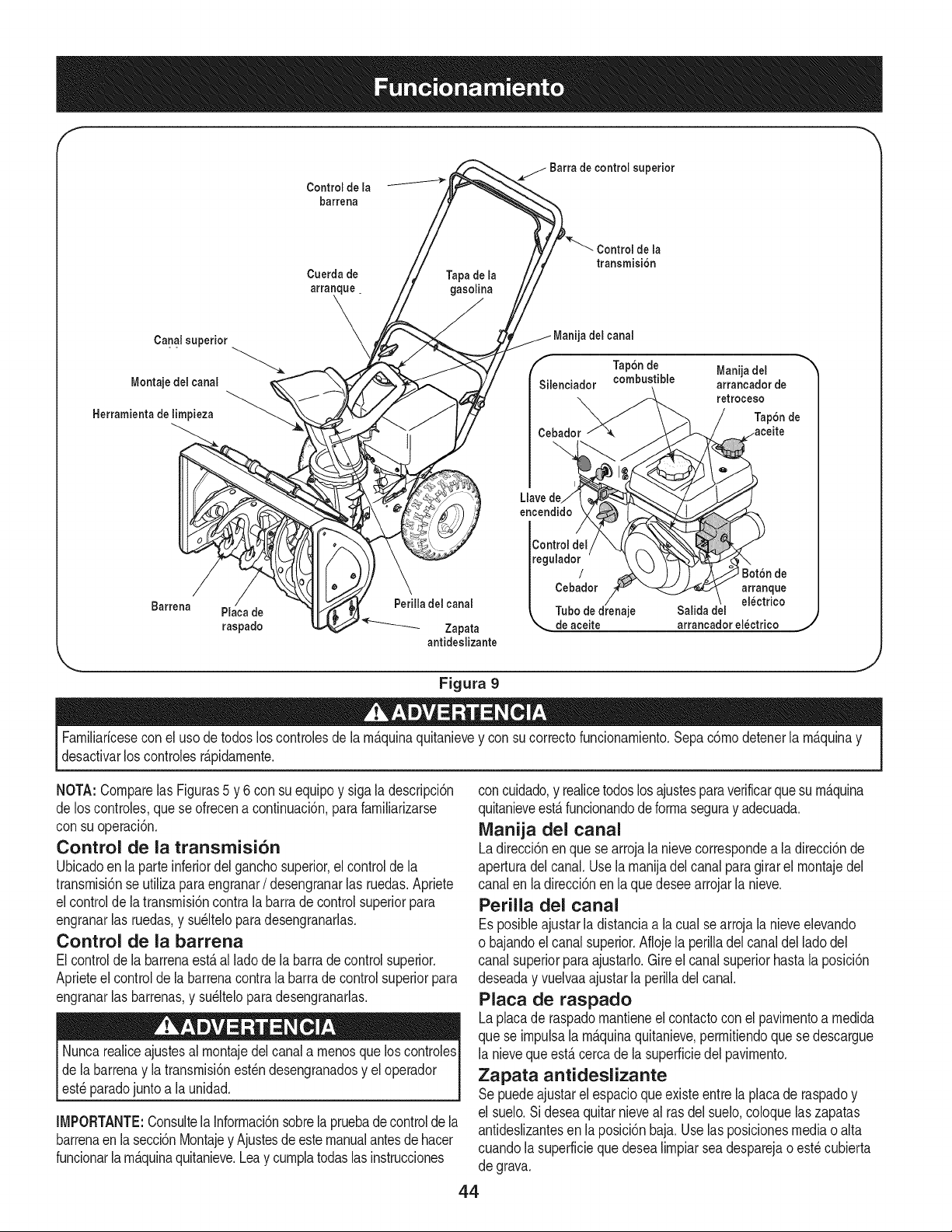
f
Control de la
barrena
de la
transmisi6n
Cuerda de Tapa de la
arranque, gasolina
\
Canal superior _ del canal
" " _ k /'- Tap6nde Manija del
Montaje del canal Silenciador combustible arrancador de
retroceso
Herramienta de limpieza
Cebador
Llave de
encendido
Barrena Placa de Perilla del canal
raspado I._.........._..._ Zapata de aceite arrancador electrico
antideslizante
Figura 9
,J
Familiaricesecon el usode todosloscontrolesde la m_.quinaquitanievey con su correctofuncionamiento.Sepac6modetenerla m_.quinay
desactivarlos controlesr_.pidamente.
NOTA:Comparelas Figuras5 y 6 con su equipoy siga ladescripci6n
de loscontroles,que se ofrecena continuaci6n,parafamiliarizarse
con suoperaci6n.
Control de la transmisi6n
Ubicadoen la parteinferiordel ganchosuperior,el controlde la
transmisi6nse utilizaparaengranar/desengranarlas ruedas.Apriete
elcontroldela transmisi6ncontrala barrade controlsuperiorpara
engranarlas ruedas,y su_ltelopara desengranarlas.
Control de la barrena
Elcontrolde la barrenaest&al ladode la barra de controlsuperior.
Aprieteel controlde labarrenacontrala barrade controlsuperiorpara
engranarlas barrenas,y su_lteloparadesengranarlas.
Nuncarealiceajustesal montajedelcanal a menosque loscontroles
dela barrenay la transmisi6nest_ndesengranadosy el operador
est_paradojuntoa la unidad.
IMPORTANTE:ConsultelaInformaci6nsobrela pruebade controlde la
barrenaenlasecci6nMontajey Ajustesde estemanualantesde hacer
funcionarla m_.quinaquitanieve.Leay cumplatodaslasinstrucciones
con cuidado,y realicetodoslos ajustesparaverificarquesu m_.quina
quitanieveest,.funcionandodeformaseguray adecuada.
Manija del canal
Ladirecci6nen que se arrojala nievecorrespondea la direcci6nde
aperturadel canal. Usela manijadel canalparagirarel montajedel
canalen ladirecci6nen la quedeseearrojarla nieve.
Perilla del canal
Esposibleajustarla distanciaa lacual searrojala nieveelevando
o bajandoelcanal superior.Aflojela perilladelcanaldel ladodel
canal superiorparaajustarlo.Gireel canalsuperiorhastala posici6n
deseaday vuelvaaajustarla perilladelcanal.
Placa de raspado
Laplacade raspadomantieneel contactocon el pavimentoa medida
que se impulsala m_.quinaquitanieve,permitiendoquese descargue
la nievequeest,. cercade la superficiedel pavimento.
Zapata antideslizante
Se puedeajustarel espacioqueexisteentre la placade raspadoy
el suelo.Si deseaquitarnieveal ras delsuelo,coloquelaszapatas
antideslizantesen laposici6nbaja. Uselasposicionesmediao alta
cuandola superficiequedesealimpiarsea desparejao est_cubierta
de grava.
44
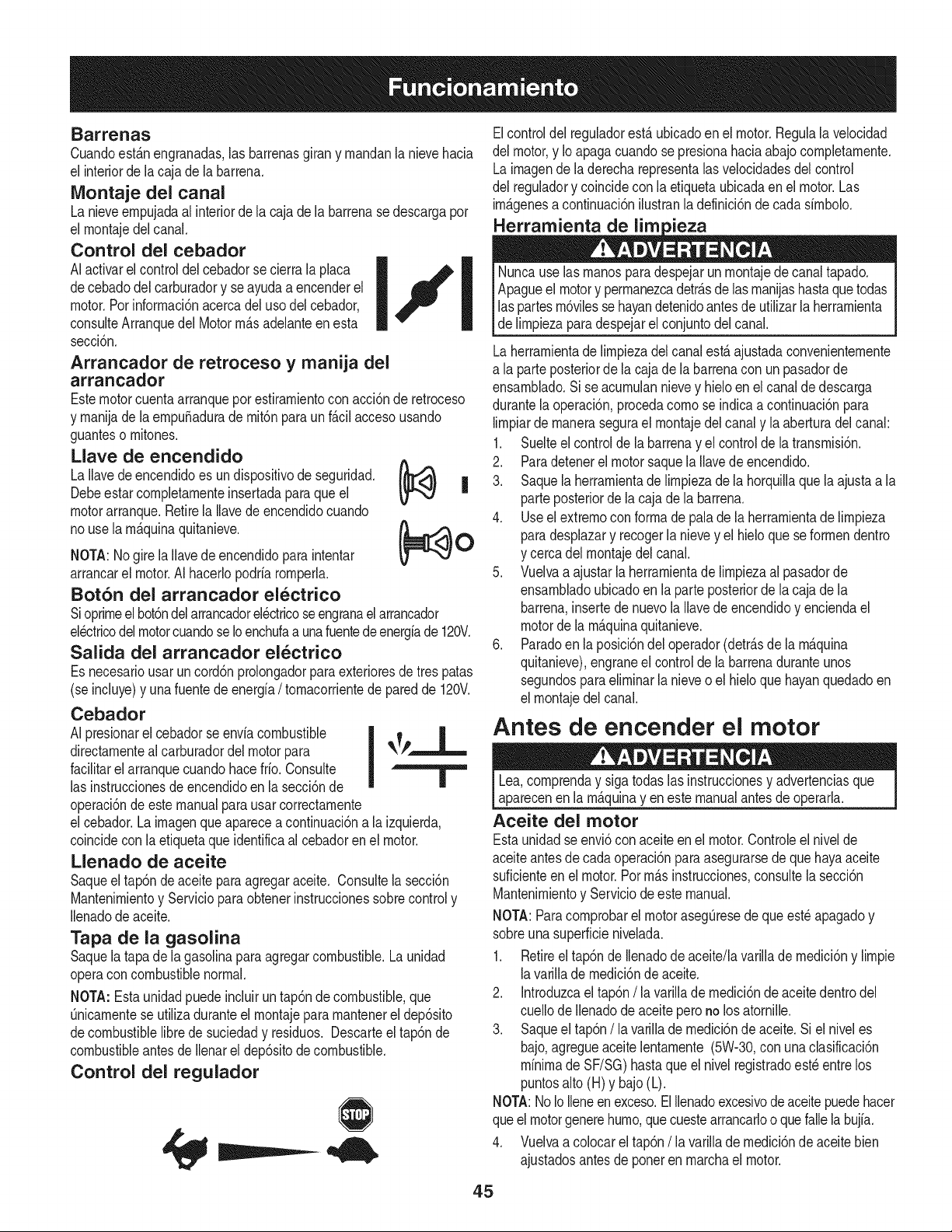
Barrenas
Cuandoest_.nengranadas,las barrenasgirany rnandanla nievehacia
el interiorde lacaja dela barrena.
Montaje del canal
La nieveernpujadaal interiordela caja dela barrenasedescargapor
el rnontajedelcanal.
Control del cebador
AIactivarel controldelcebadorse cierra laplaca _ _
decebadodel carburadory se ayudaa encenderel
I
F
I
motor.Pot inforrnaci6nacercadeluso delcebador,
consulteArranquedel Motorrn_.sadelanteenesta
secci6n.
Arrancador de retroceso y manija del
arrancador
Estemotorcuentaarranqueporestirarnientocon acci6nde retroceso
y rnanijade laernpu_aduradernit6nparaun f_.cilaccesousando
guanteso rnitones.
Llave de encendido
A
La Ilavede encendidoes undispositivode seguridad. I_
Debeestarcornpletarnenteinsertadaparaque el V ,_,, |
motorarranque.Retirela Ilavede encendidocuando
nouse la rn_.quinaquitanieve. _ O
V -','
NOTA:Nogire laIlavedeencendidoparaintentar
arrancarel motor.AIhacerlopodriarornperla.
Bot6n del arrancador electrico
Sioprirneelbot6ndelarrancadorelectricoseengranaelarrancador
el_ctricodel motorcuandose Ioenchufaa unafuentede energfade 120V.
Salida del arrancador el_ctrico
Es necesariousar un cord6nprolongadorparaexterioresde trespatas
(se incluye)y una fuentede energfa/ tornacorrientede paredde 120V.
Cebador
AI presionarel cebadorse enviacombustible
directarnenteal carburadordelmotor para -, r -----,,-----
facilitarel arranquecuandohacefrio. Consulte I
las instruccionesde encendidoenla secci6nde |
operaci6nde este manualparausarcorrectarnente
el cebador.La irnagenque apareceacontinuaci6na la izquierda,
coincidecon la etiquetaque identificaal cebadorenel motor.
Llenado de aceite
Saqueeltap6n de aceite paraagregaraceite. Consultelasecci6n
Mantenirnientoy Servicioparaobtenerinstruccionessobrecontroly
Ilenadode aceite.
Tapa de la gasolina
Saquela tapade lagasolinaparaagregarcombustible.Launidad
operacon combustiblenormal.
NOTA:Esta unidadpuedeincluirun tap6nde combustible,que
Onicarnentese utilizaduranteel rnontajepararnantenereldep6sito
decombustiblelibredesuciedady residuos. Descarteel tap6nde
combustibleantesde Ilenareldep6sitode combustible.
Control del regulador
===..--
Elcontroldel reguladorest,. ubicadoenel motor.Regulalavelocidad
del motor,y Io apagacuandose presionahaciaabajocornpletarnente.
Lairnagende laderecharepresentalasvelocidadesdel control
del reguladory coincidecon la etiquetaubicadaen el motor.Las
imP.genesa continuaci6nilustranla definici6nde cadasirnbolo.
Nuncause lasrnanosparadespejarunrnontajede canaltapado.
Apagueel motory perrnanezcadetr_.sde lasrnanijashastaquetodas
laspartesrn6vilessehayandetenidoantesde utilizarla herrarnienta
_de rnpeza para despejare conjuntode cana.
Laherrarnientade lirnpiezadel canalest,. ajustadaconvenienternente
a la parteposteriorde la cajade labarrenacon un pasadorde
ensarnblado.Si seacurnulannievey hieloen elcanal dedescarga
durantelaoperaci6n,procedacornose indicaa continuaci6npara
lirnpiarde rnanerasegurael rnontajedel canaly laaberturadel canal:
1. Suelteel controlde labarrenay el controlde la transrnisi6n.
2. Paradetenerel motorsaquela Ilavede encendido.
3. Saquela herrarnientade lirnpiezadela horquillaquela ajustaa la
parteposteriorde lacaja dela barrena.
4. Useel extrernocon forrnade palade la herrarnientade lirnpieza
paradesplazary recogerla nievey el hieloque seforrnendentro
y cercadel rnontajedel canal.
5. Vuelvaa ajustarlaherrarnientade lirnpiezaal pasadorde
ensarnbladoubicadoen laparte posteriorde lacaja dela
barrena,insertedenuevolaIlavede encendidoy enciendael
motordela rn_.quinaquitanieve.
6. Paradoen laposici6ndeloperador(detr_.sde la rn_.quina
quitanieve),engraneel controlde labarrenaduranteunos
segundosparaelirninarlanieveo el hieloque hayanquedadoen
el rnontajedelcanal.
Antes de encender el motor
Lea,cornprenday sigatodas las instruccionesy advertenciasque
aparecenen la rn_.quinayen estemanualantesde operarla.
Aceite del motor
Estaunidadse envi6con aceiteen el motor.Controleel nivelde
aceiteantesdecada operaci6nparaasegurarsedequehayaaceite
suficienteenel motor.Porrn_.sinstrucciones,consultela secci6n
Mantenirnientoy Serviciode este manual.
NOTA:Paracornprobarel motorasegQresede que est_apagadoy
sobreunasuperficienivelada.
1. Retireeltap6nde Ilenadodeaceite/lavarilladernedici6ny lirnpie
lavarillade rnedici6ndeaceite.
2. Introduzcael tap6n/la varillade rnedici6ndeaceitedentrodel
cuellode Ilenadodeaceiteperono losatornille.
3. Saqueel tap6n/la varillade rnedici6nde aceite.Si el niveles
bajo,agregueaceitelentarnente(5W-30,con unaclasificaci6n
minimade SF/SG)hasta que el nivelregistradoest_entre los
puntosalto (H) y bajo(L).
NOTA:NoIo Ileneenexceso.ElIlenadoexcesivode aceitepuedehacer
queel motorgenerehurno,quecuestearrancarlooquefallela bujia.
4. Vuelvaa colocarel tap6n/ la varillade rnedici6nde aceitebien
ajustadosantesde poneren rnarchael motor.
45
Gasolina
Utiiice gasolina para autom6viles (sin plomo o bajo contenido de plomo
para minimizar los dep6sitos en la cfimara de combusti6n) con un minimo
de 87octanos. Se puede usar gasolina con hasta un 10% de etanol o un
15% de MTBE(eter metilico terciario-bufilico). Nunca use una mezcla
de aceite y gasolina ni gasolina sucia. Evite que se introduzca suciedad,
polvo o agua en ei dep6sito de combustible. NO utilice gasolina E85.
• Cargue combustible en un a.reabien ventiladay con el motor
apagado. No fume ni permita llamas o chispas en el lugar donde se
carga combustible o se aimacena ia gasolina.
• No iiene en exceso el dep6sito de combustible. Despues de cargar
combustible, asegurese de que el tap6n del dep6sito este bien
cerrado y asegurado.
• Tenga cuidado de no derramar combustible ai reaiizar ia recarga. El
combustible derramado o sus vapores se pueden incendiar. Si se
derrama combustible, asegQresede que el firea este seca antes de
arrancar el motor.
• Evite el contacto repetido o prolongado con la piel o la inhaiaci6n de
los vapores.
Tengamuchocuidadoaltrabajarcongasolina.Lagasolinaessumamente
inflamabley susvaporespuedencausarexplosiones.Nuncaagregue
combustiblea lam@uinaeninterioreso mientrasel motorestacalienteo en
funcionamiento.Apaguecigarrillos,cigarros,pipasyotrasfuentesdecombusti6n.
1,
2.
Antes de sacar el tap6n paracargar combustible, limpie airededor.
En ei dep6sito de combustible hay un indicador de nivel. Llene el
dep6sito hasta Ilegar al nivel de combustible del indicador.Vea el
recuadro de la Figura 10.Tenga cuidado de no Ilenaren exceso.
Encendido del motor
NO use ei arrancador electrico en ninguna circunstancia.
1. Conecte el prolongador a la salida situada en ia superficie del motor.
Conecte ei otto extremo del prolongador a un tomacorriente de CA,
120voltios con conexi6n a tierra, para tres patas, en un firea bien
ventiiada.
2. Mueva la palanca de control del regula_o..rhastala posici6n FAST
(rfipido, representado pot una liebre) _ .
3. Mueva la palanca del cebador hasta la posici6n ON (encendido)
I.,.e'l . Si el motor estfi caliente, ubique el cebador en la
posici6n
OFF (apagado).
4. Presioneel bot6ndel cebador tres a cinco (3-5) veces, asegurfindose
de cubrirei orificio de ventilaci6ncuando io haga. Si el motor estfi
caliente, presioneel bot6n del cebador una sola vez. Cubra siempreel
orificiode ventiiaci6ncuando optima el bot6n del cebador. Si hacefrio
puede resultar necesariorepetir el cebado.
5. Presioneel bot6n del arrancador para arrancar el motor. Una vez
encendido el motor, suelte inmediatamente el bot6n dei arrancador.
Elarrancador electrico tiene una protecci6n contra sobrecarga
t@mica; el sistema se apagarfi transitoriamente para permitir que se
enfrie el arrancador en caso que se sobrecargue.
6. A medida que se calienta el motor, rote ientamente ei control dei
cebador hasta la posici6n OFF (apagado). Si el motor se detiene,
vuelva a encenderlo, hfigalo funcionar con el cebador en su posici6n
media durante un iapso breve y luego gire lentamente el cebador
hasta la posici6n OFF (apagado).
7. Una vez que el motor este en funcionamiento,desconecte del
arrancador ei@trico ei cable de aiimentaci6n. Para desconectarlo,
desenchufe siempre el extremo que estfi enchufado ai tomacorriente
de pared antes de desenchufarel extremo opuesto que estfi
conectado ai motor.
Arrancador de retroceso
Siempremantengalas manosy los piesalejadosde las partesm6viles.No
utilicefluidos comprimidosparaarrancar.Losvaporesson inflamables.
NOTA: Para ubicar todos los controles dei motor que se mencionan en
esta secci6n, consulte ia Figura 9 de ia pfigina 12.
NOTA: Dejeque ei motor se caiiente durante unos minutos tras el
arranque. Ei motor no desarrollarfi toda su potencia hasta que aicance
temperaturasoperativas.
1. Asegurese de que ei control de la barrena y el control de ia
transmisi6n esten en posici6n desengranada (sin presionar).
2. Inserte ia iiave de encendido en la ranura. AsegQresede que entrea
presi6n en su iugar. No intente girar la Ilave.
NOTA: El motor no puede arrancar si la iiave no estfi completamente
insertada en ei interruptor de encendido.
Arrancador el_ctrico
Elarrancadorelectricoopcionalest_ equipadocon un cable de alimentaci6n
de tres hilosconectadoa tierra y unenchufey est_dise_adopara
operarcon corrientedomesticaCA, 120voltios.Debeser utilizadocon
un recept_culoparatres patascorrectamenteconectadoa tierraen todo
momentoparaevitarla posibilidadde descargaselectricas.Sigatodas las
instruccionescuidadosamenteantesde operarel arrancadorelectrico.NO
utiliceel arrancadorel@tricoen la Iluvia.
Determine si el cableado de su hogar es un sistema de tres cables
conectado a tierra. Consulte con un electricista matriculadosi no estfi
seguro.
Si tiene un receptficulo de tres terminaies con conexi6n a tierra, proceda
de la siguiente manera: Si el cableado de su hogar no es el adecuado,
Notire de la manijadel arrancadormientrasel motorest_ en marcha.
1. Mueva la palanca de control del regula_orhasta la posici6n FAST
(rfipido, representado pot una liebre) ,_ .
2. Mueva la palanca del cebador hasta la posici6n ON (encendido)
J,,_'J (encendido con el motor en frio). Si el motor estfi caliente,
ubique el cebador en la posici6n OFF (apagado).
3. Presioneel bot6n del cebador tres a cinco (3-5) veces, asegurfindose
de cubrir ei orificio de ventilaci6n cuando io haga. Si el motor est,.
caliente, presione el bot6n del cebador una sola vez. Cubra siempre ei
orificio de ventiiaci6n cuando optima el bot6n del cebador. Si hace frio
puede resultar necesario repetir el cebado.
4. Jale suavemente la manija del arrancador hasta que comience a
ofrecer resistencia, luego jfilela rfipidamente y con fuerza para superar
la compresi6n. No suelte la manija ni permita que se desenganche.
Vuelva la soga LENTAMENTEa su posici6n original. De ser necesario,
repita este paso.
5. A medida que se calienta el motor, rote ientamente ei control dei
cebador hasta la posici6n OFF (apagado). Si el motor se detiene,
vuelva a encenderlo, hfigalo funcionar con el cebador en su posici6n
media durante un iapso breve y luego gire lentamente el cebador
hasta la posici6n OFF (apagado).
46
Paraevitarque el motorfuncionesin control,nuncadejela m_quinasin
vigilanciamientrasest_en marcha.Apagueel motorluegode usarloy
saque la Ilavedeencendido.
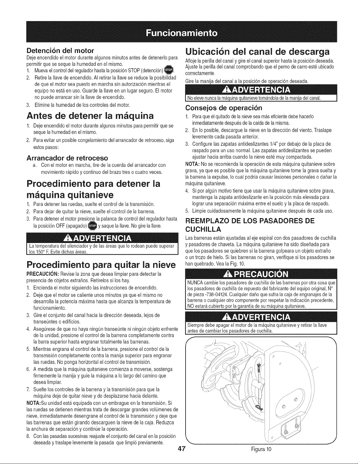
Detenci6n del motor
Deje encendido el motor durante aigunos minutos antes de detenerlo para
permitir que se seque la humedad en el mismo.
1. Muevael controldel reguladorhastala posici6nSTOP(detenci6n)1,_.
2. Retire ia ilave de encendido. AI retirar la ilave se reduce la posibilidad
de que el motorsea puesto en marcha sin autorizaci6n mientras el
equipo no esta.en uso. Guarde la iiave en un lugar seguro. El motor
no puede arrancar sin la Ilave de encendido.
3. Elimine ia humedad de los controles del motor.
Antes de detener la m quina
1. Deje encendidoel motorduranteaigunos minutos para permitirque se
sequela humedaden el mismo.
2. Paraevitar un posible congelamientodel arrancadorde retroceso,siga
estospasos:
Arrancador de retroceso
a. Con el motor en marcha,tire de la cuerda del arrancador con
movimiento ra.pidoy continuo del brazo tres o cuatro veces.
Procedimiento para detener la
m quina quitanieve
1. Para detener las ruedas, suelte ei control de la transmisi6n.
2. Paradejar de quitar la nieve, suelte el control de la barrena.
3. Paradetener ei motor presionela palancade control del reguladorhasta
la posici6nOFF (apagado)_ y saque laIlave.No gire la Ilave.
La temperaturadel silenciadory de las_reas que Io rodeanpuedesuperar
los 150o F.Evite dichas_reas.
Procedimiento para quitar la nieve
PRECAUCION: Revise la zona que desea limpiar para detectar la
presencia de objetos extraSos. Retirelos si los hay.
1. Encienda el motor siguiendo las instrucciones de encendido.
2. Deje que el motor se caliente unos minutos ya que el mismo no
desarrolla la potencia ma.ximahasta que alcanza la temperatura de
funcionamiento.
3. Gire el conjunto del canal hacia la direcci6n deseada, lejos de
transeuntes o edificios.
4. Aseg_resede que no haya ning_n transeunte ni ning_n objeto enfrente
de la unidad, presione el control de la barrena completamente contra
la barra superior hasta engranar totalmente las barrenas.
5. Mientras engrana el control de la barrena, presione el control de la
transmisi6n completamente contra la manija superior para engranar
las ruedas. No ponga horizontal el control de transmisi6n.
6. A medida que la ma.quinaquitanieve comienza a moverse, sostenga
firmemente la manija y guie la ma.quinaa Io largo del camino que
desea limpiar.
7. Suelte los controles de la barrena y la transmisi6n para que la
ma.quinadeje de quitar nieve y de desplazarse hacia delante.
NOTA:Su unidad esta.equipada con un embragueen la transmisi6n. Si
las ruedas se detienen mientras trata de descargar grandes vol_menes de
nieve, inmediatamente desengrane el control de la transmisi6n y deje que
las barrenas que esta.ngirando descarguen la nieve de la caja. Reduzca
la anchura de separaci6ny continue la operaci6n.
8. Con las pasadassucesivas reajusteel conjuntodel canalen la posici6n
deseaday traslape levementela pasada que limpi6 previamente.
47
Ubicaci6n del canal de descarga
Afloje la perilladel canal y gireel canal superior hasta la posici6ndeseada.
Ajuste la perilladel canal comprobandoque el perno de carroeste ubicado
correctamente.
Girela manija del canal a la posici6n de operaci6n deseada.
Noelevenuncalam_uin%_A_uitanievetom_ndolade la maniladel canal.
Consejos de operaci6n
1. Paraqueel quitadode la nievesea ma.seficientedebe hacerlo
inmediatamentedespuesde lacaida de la misma.
2. En io posible, descargue la nieve en la direcci6n del viento. Traslape
levementecada pasada anterior.
3. Configure ias zapatas antideslizantes 1/4" pot debajo de la placa de
raspado para un uso normal. Las zapatas antideslizantes se pueden
ajustar hacia arriba cuando ia nieve este muycompactada.
NOTA: No se recomienda ia operaci6n deesta ma.quinaquitanieve sobre
grava, ya que es posible que la ma.quinaquitanieve tome la grava suelta y
la barrena ia expulse, Io cuai podria causar lesiones personales o da_ar la
ma.quinaquitanieve.
4. Si pot aigOnmotivo tiene que usar ia ma.quinaquitanieve sobre grava,
mantenga la zapata antideslizante en ia posici6n ma.selevada para
Iograr una separaci6n ma.ximaentreel suelo y ia placa de raspado.
5. Limpie cuidadosamente la ma.quinaquitanieve despues de cada uso.
REEMPLAZO DE LOS PASADORES DE
CUCHILLA
Las barrenas esta.najustadas ai eje espirai con dos pasadores de cuchilla
y pasadoresde chaveta. La maquina quitanieve ha sido dise_ada para
que los pasadores se quiebren si la barrena goipeara un objeto extra_o
o un trozo de hielo. Si las barrenas no giran, verifique si los pasadores se
hanquebrado. Vea la Fig. 10.
NUNCAcambie los pasadoresde cuchillade lasbarrenaspot otra cosaque I
los pasadoresdecuchillade repuestodel fabricantedel equipo original,No I
de pieza-738-04124.Cualquierda_oque sufra la cajade engranajesde la I
barrenao cualquierotro componentepot respetarlaindicaci6nprecedente, I
NO estarAcubierto orla aranfiade su mA ulna uitanieve.
Siempredebe apagarel motorde la m_quinaquitanievey retirar la Ilave
antesde cambiarlospasadoresde cuchilla.
, ', ............
\\
/
/
/ ©
Figura 10
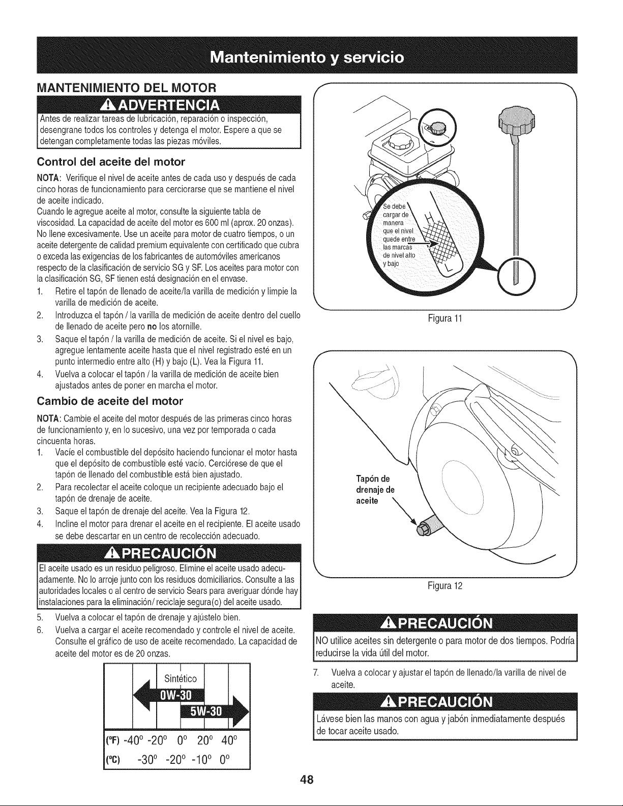
MANTENIMIENTO DEL MOTOR
Antes de realizar tareas de lubricaci6n, reparaci6n o inspecci6n,
desengrane todos los controles y detenga ei motor. Esperea que se
detengan completamente todas las piezas m6viles.
Control del aceite del motor
NOTA: Verifique ei nivel de aceite antes de cada uso y despues de cada
cinco horas de funcionamiento para cerciorarse que se mantiene el nivel
de aceite indicado.
Cuandole agregueaceite ai motor,consulte ia siguientetabla de
viscosidad. La capacidadde aceitedel motores 600 ml (aprox.20 onzas).
No iiene excesivamente.Use un aceite paramotor de cuatro tiempos,o un
aceitedetergentede caiidadpremium equivalentecon certificadoque cubra
o exceda ias exigenciasde los fabricantesde autom6vilesamericanos
respectode la clasificaci6n de servicio SG y SF.Los aceites para motor con
la clasificaci6nSG, SFtienen esta.designaci6n en el envase.
1. Retire el tap6n de ilenado de aceite/la varilla de medici6n y limpie la
variiia de medici6n de aceite.
2. Introduzca el tap6n /ia variiia de medici6n de aceite dentro del cuello
de ilenado de aceite pero no los atorniile.
3. Saque el tap6n /la varilla de medici6n de aceite. Si el nivel es bajo,
agregue ientamente aceite hasta que ei nivei registrado este en un
punto intermedioentre alto (H) y bajo (L). Vea la Figura 11.
4. Vueiva a colocar el tap6n /ia varilia de medici6n de aceite bien
ajustados antes de poner en marcha el motor.
Cambio de aceite del motor
NOTA: Cambie ei aceite dei motor despues de ias primeras cinco horas
de funcionamientoy, en Io sucesivo, una vez por temporada o cada
cincuenta horas.
1. Vacie el combustible dei dep6sito haciendo funcionar ei motor hasta
que ei dep6sito de combustible este vacio. Cerci6rese de que el
tap6n de Ilenadodel combustible esta.bien ajustado.
2. Para recolectar el aceite coloque un recipiente adecuado bajo el
tap6n de drenaje de aceite.
3. Saque el tap6n de drenaje del aceite. Vea la Figura 12.
4. Incline el motor para drenar el aceite en el recipiente. Elaceite usado
se debe descartar en un centro de recolecci6n adecuado.
El aceite usadoes un residuo peligroso.Elimineei aceite usadoadecu- I
adamente. NoIo arroje juntocon los residuosdomiciliarios. Consultealas
autoridadeslocales o ai centrode servicioSears para averiguard6nde hay
nstaac ones para a e m nac 6n/rec c a e segura(o)de ace te usado. ]
5. Vuelva a colocar el tap6n de drenaje y ajQstelobien.
6. Vueiva a cargar el aceite recomendado y controle ei nivel de aceite.
Consulte el gra.ficode uso de aceite recomendado. La capacidad de
aceite del motor es de 20 onzas.
[
Sint_tico
(°F)-40 o-20 o 0o 20o 40o
(°C) -30° -20° -10 ° 0°
f
q!
q,
las mamas
de nivel alto
Figura11
J
Tap6n de
drenaje de
aceite
Figura12
NOutilice aceitessin detergenteo paramotordedos tiempos.Podria
reducirsela vida0til del motor.
7. Vuelva a colocar y ajustar el tap6n de Ilenado/la varilla de nivel de
aceite.
L_.vesebien las manoscon aguay jab6ninmediatamentedespu_s
detocaraceiteusado.
48
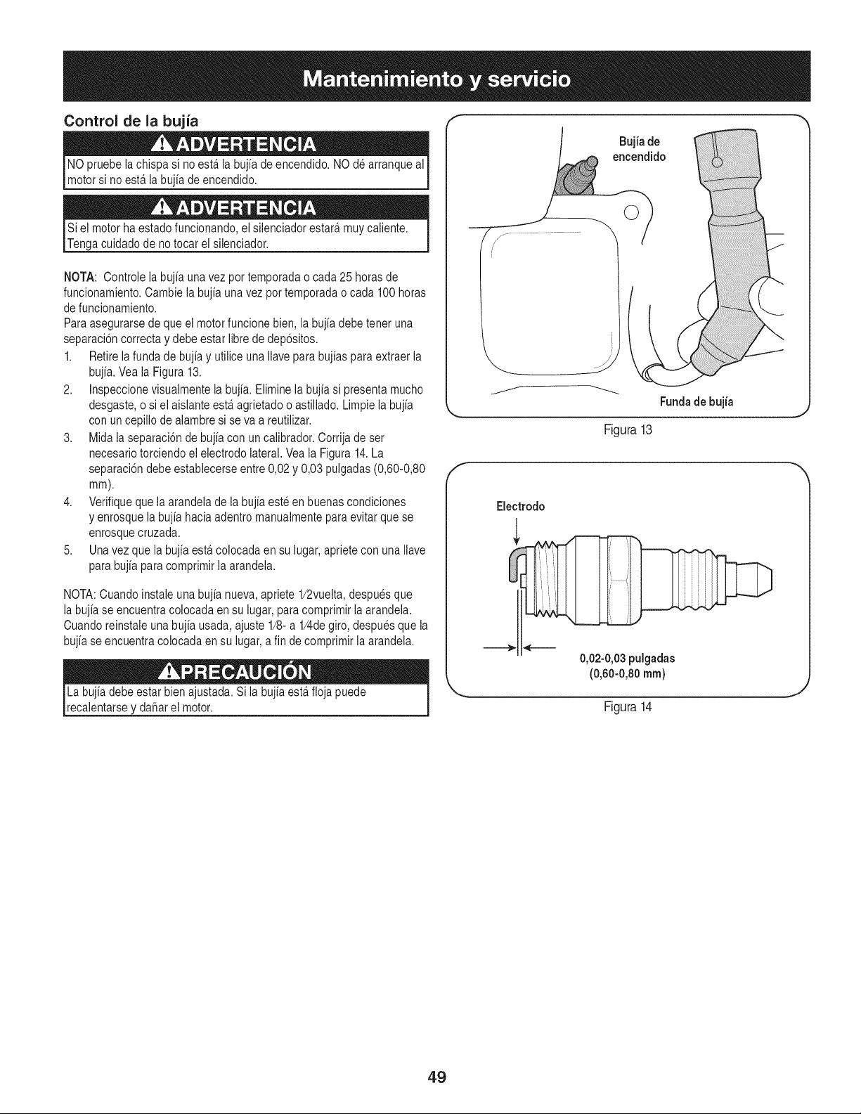
Control de la bujia
NO pruebe lachispa si no esta.la bujia de encendido. NO de arranque al
motor si no esta.la bujia de encendido.
Si el motor ha estado funcionando, el silenciador estara,muy caiiente.
Tenga cuidado de no tocar el silenciador.
NOTA: Controle la bujia una vez por temporada o cada 25 horas de
funcionamiento. Cambie la bujia una vez por temporada o cada 100 horas
de funcionamiento.
Para asegurarse de que el motor funcione bien, la bujia debe tener una
separaci6n correcta y debe estar libre de dep6sitos.
1. Retire la funda de bujia y utilice una Ilave para bujias para extraer la
bujia. Vea la Figura 13.
2. Inspeccione visualmente la bujia. Elimine la bujia si presenta mucho
desgaste, o si el aislante esta.agrietado o astiilado. Limpie la bujia
con un cepillo de aiambre si se va a reutiiizar.
3. Mida la separaci6n de bujia con un calibrador. Corrija de set
necesario torciendo el electrodo lateral. Vea la Figura 14. La
separaci6n debe establecerse entre 0,02 y 0,03 pulgadas (0,60-0,80
mm).
4. Verifique que la arandela de la bujia este en buenas condiciones
y enrosque la bujia hacia adentro manualmente para evitar que se
enrosque cruzada.
5. Una vez que la bujia esta.colocada en su lugar, apriete con una Ilave
para bujia para comprimir la arandela.
NOTA: Cuando instale una bujia nueva, apriete 1/2vuelta, despues que
la bujia se encuentra colocada en su lugar, paracomprimir laarandela.
Cuando reinstale una bujia usada, ajuste 1/8-a 1/4degiro, despuesque la
bujia se encuentra colocada en su lugar, a fin de comprimir la arandela.
La bujia debe estar bienajustada. Si la bujia esta.floja puede I
reca entarse y da_ar e motor. I
Bujia de
encendido
Fundade bujia
Figura13
Electrodo
0,02-0,03 pulgadas
(0,60-0,80 ram)
Figura14
49
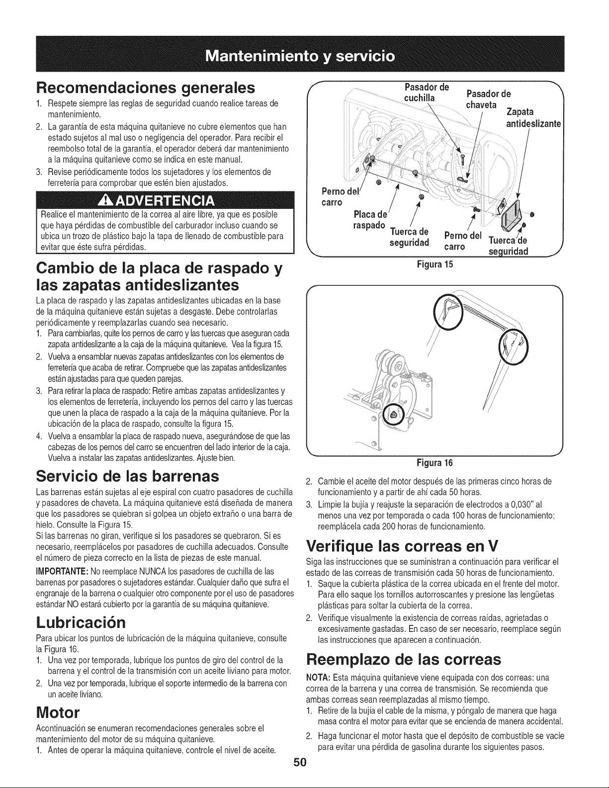
Recomendaciones generales
1. Respete siempre las regias de seguridad cuando reaiice tareas de
mantenimiento.
2. La garantia de esta ma.quinaquitanieve no cubre elementos que han
estado sujetos al real uso o negligencia del operador. Pararecibir el
reembolso total de la garantfa, ei operador debera,dar mantenimiento
a la ma.quinaquitanieve como se indica en este manual.
3. Revise peri6dicamente todos los sujetadores y los elementos de
ferreterfa para comprobar que esten bien ajustados.
Realice el mantenimientode ia correa ai aire iibre, ya que es posible
que haya perdidas de combustible dei carburador incluso cuando se
ubica un trozo de pla.sticobajo la tapa de Ilenadode combustible para
evitar que este sulfa perdidas.
Carnbio de la plata de raspado y
las zapatas antideslizantes
La placa de raspadoy ias zapatasantideslizantes ubicadas en ia base
de ia ma.quinaquitanieve esta.nsujetas a desgaste. Debe controlarlas
peri6dicamente y reemplazarlas cuando sea necesario.
1. Paracambiarlas,quitelospernosde carroy lastuercasqueasegurancada
zapataantideslizantea iacajade ia ma.quinaquitanieve.Veaiafigura 15.
2. Vueivaa ensamblarnuevaszapatasantideslizantescon loselementosde
ferreterfaqueacabade retirar.Compruebequelaszapatasantideslizantes
esta.najustadasparaquequedenparejas.
3. Pararetirarla placaderaspado:Retireambas zapatas antideslizantesy
los elementosde ferreterfa,incluyendolos pernosdel carro y las tuercas
que unen la placade raspado a la caja de la ma.quinaquitanieve.Por la
ubicaci6n de ia placade raspado,consulte ia figura 15.
4. Vueivaa ensamblariaplaca de raspadonueva,asegura.ndosede que ias
cabezasde los pernosdel carro seencuentrendel ladointeriorde la caja.
Vuelvaa instaiarlaszapatasantideslizantes.Ajustebien.
Servicio de las barrenas
Las barrenas esta.nsujetas al eje espiral con cuatro pasadores de cuchilla
y pasadores de chaveta. La ma.quinaquitanieve esta.dise_ada de manera
que los pasadoresse quiebransi golpea un objeto extra_o o una barra de
hielo. Consulte ia Figura 15.
Si las barrenas no giran, verifique si los pasadores se quebraron. Si es
necesario, reempla.celospot pasadores de cuchiiia adecuados. Consulte
el nOmerode pieza correcto en la lista de piezas de este manual.
IMPORTANTE:NoreemplaceNUNCAlospasadoresde cuchillade las
barrenaspot pasadoreso sujetadoresestAndar.CualquierdaSoquesufra el
engranajede la barrenao cualquierotto componentepor el uso de pasadores
esta.ndarNO estara,cubierto pot lagarantfade su ma.quinaquitanieve.
Lubricaci6n
Para ubicar los puntos de lubricaci6n de la ma.quinaquitanieve, consulte
la Figura 16.
1. Una vez pot temporada, lubrique los puntos de giro del control de ia
barrena y ei control de la transmisi6n con un aceite liviano para motor.
2. Una vezpor temporada,lubriqueel soporteintermediode labarrenacon
un aceiteliviano.
Motor
Acontinuaci6n se enumeran recomendacionesgenerales sobre el
mantenimiento dei motor de su ma.quinaquitanieve.
1. Antes de operar la ma.quinaquitanieve, controle el nivel de aceite.
f Pasadorde "_
cuchilla Pasadorde
chaveta
....... Zapata
antideslizante
°°"° / !ii
raspado Tuerca de Perno del Tuel le
seguridad carro
_ seguridad
Figura 15
J
i/
/ /
/
/
Figura 16
2. Cambie el aceite del motor despues de ias primeras cinco horas de
funcionamiento y a partir de ahf cada 50 horas.
3. Limpie la bujfa y reajuste la separaci6n de electrodos a 0,030" al
menos una vez por temporada o cada 100 horas defuncionamiento;
reempla.celacada 200 horas de funcionamiento.
Verifique las correas en
V
Siga las instrucciones que se suministran a continuaci6n para verificar el
estado de ias correas de transmisi6n cada 50 horas de funcionamiento.
1. Saque la cubierta pia.sticade la correa ubicada en el frente dei motor.
Para elio saque los tornilios autorroscantes y presione las lengOetas
pla.sticasparasoltar ia cubierta de la correa.
2. Verifique visuaimente la existencia de correas rafdas, agrietadas o
excesivamente gastadas. En caso de set necesario, reemplace segOn
las instrucciones que aparecen a continuaci6n.
Reemplazo de las correas
NOTA: Esta ma.quinaquitanieve viene equipada con dos correas: una
correa de ia barrena y una correa de transmisi6n. Se recomienda que
ambas correas sean reemplazadas ai mismo tiempo.
1. Retirede labujia el cablede la misma, y p6ngalode maneraque haga
masa contra el motorpara evitarque se encienda de maneraaccidental.
2. Hagafuncionar el motor hasta que el dep6sito de combustible se vacfe
para evitar una perdida de gasolina durante los siguientes pasos.
5O
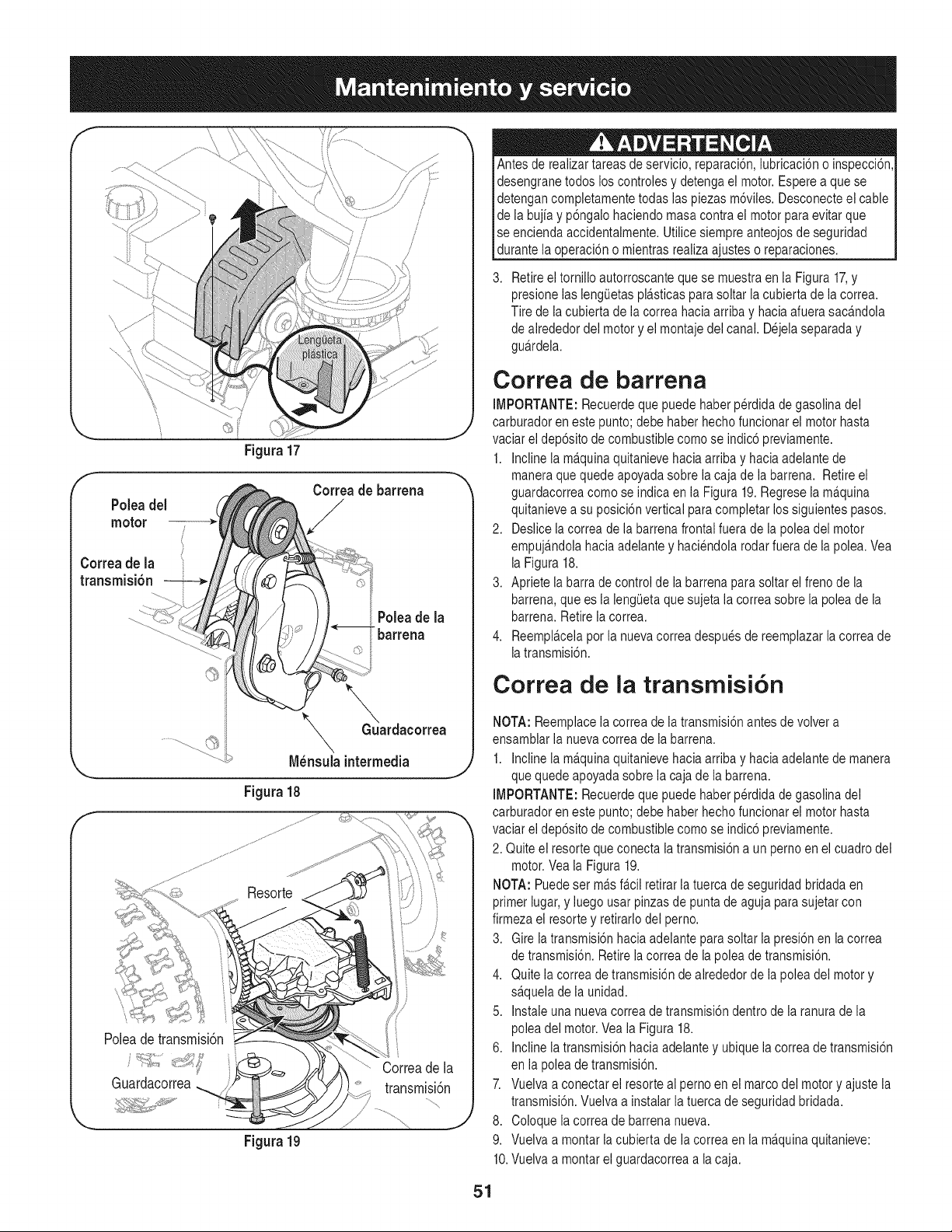
f
Figura 17
f
Correade barrena
Poleadel
motor
Correa de la
transmisi6n
t
Poleade la
t_barrena
f
_GuGuardacorrea
\
N_nsuia intermedia
Figura 18
Poleadetransmisi6n
Guardacorrea
Figura19
Antes de realizartareas de servicio, reparaci6n, iubricaci6n o inspecci6n,
desengrane todos los controles y detenga el motor. Espere a que se
detengan completamente todas ias piezas m6viles. Desconecte el cable
de la bujia y p6ngalo haciendo masa contra el motor para evitar que
se encienda accidentalmente. Utilice siempre anteojosde seguridad
_durante a operac 6n o m entras rea za a usteso reparac ones.
Retireel torniilo autorroscante que se muestra en ia Figura 17,y
presione las iengietas pla.sticasparasoltar ia cubierta de la correa.
Tire de ia cubierta de ia correa haciaarriba y hacia afuera saca.ndola
de alrededor del motor y el montaje del canal. Dejela separada y
gua.rdela.
Correa de barrena
IMPORTANTE: Recuerde que puede haber perdida de gasolina del
carburador en este punto; debe haber hecho funcionar el motor hasta
vaciar el dep6sito de combustible como se indic6 previamente.
1. Incline ia ma.quinaquitanieve hacia arriba y hacia adeiante de
maneraque quede apoyada sobre la caja de la barren& Retire el
guardacorrea como se indica en la Figura 19.Regrese ia ma.quina
quitanieve a su posici6n vertical para completar los siguientes pasos.
2. Deslice la correa de la barrena frontal fuera de la polea del motor
empuja.ndolahacia adelante y haciendola rodar fuera de la polea. Vea
la Figura 18.
3. Apriete la barra de control de ia barrena para soltar el freno de la
barrena, que es la lengieta que sujeta la correa sobre la polea de la
barrena. Retire la correa.
4. Reempla.celapor la nueva correa despues de reemplazar la correa de
latransmisi6n.
Correa de la transmisi6n
NOTA: Reemplacela correa de la transmisi6n antes de volver a
ensamblar la nueva correa de la barrena.
1. Incline ia m£quina quitanieve hacia arriba y hacia adelante de manera
que quede apoyada sobre la caja de la barren&
IMPORTANTE: Recuerde que puede haber perdida de gasolina del
carburador en este punto; debe haber hecho funcionar el motor hasta
vaciar ei dep6sito de combustible como se indic6 previamente.
2. Quite el resorte que conecta la transmisi6n a un perno en el cuadro del
motor.Vea ia Figura 19.
NOTA: Puedeset m£s fa.ciiretirar la tuerca de seguridad bridada en
primer iugar, y iuego usar pinzasde punta de aguja para sujetar con
firmeza el resorte y retirarlo del perno.
3. Gire ia transmisi6n hacia adelante para soltar ia presi6n en la correa
de transmisi6n. Retire ia correa de la polea de transmisi6n.
4. Quite ia correa de transmisi6n dealrededor de la polea del motor y
sa.quelade la unidad.
5. Instale una nueva correa de transmisi6n dentro de la ranura de la
polea del motor.Vea la Figura 18.
6. incline ia transmisi6n hacia adelante y ubique la correa de transmisi6n
en la polea de transmisi6n.
7. Vueiva a conectar el resorte al pemo en el marco del motor y ajuste la
transmisi6n. Vueiva a instaiar la tuerca de seguridad bridada.
8. Coloque la correa de barrena nueva.
9. Vuelva a montar la cubierta de ia correa en la ma.quinaquitanieve:
10.Vuelva a montar el guardacorrea a la caja.
51
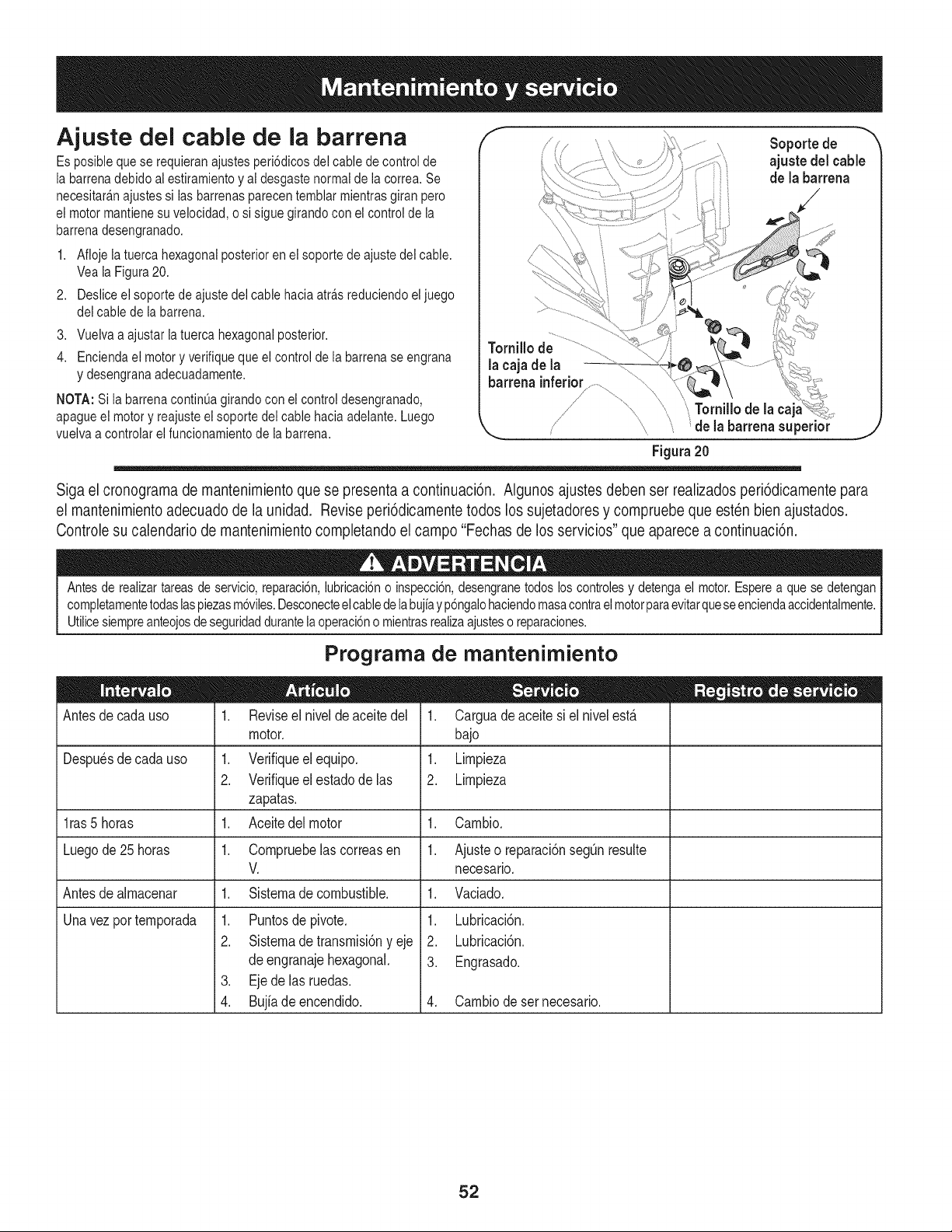
Ajuste del cable de la barrena
Es posible que se requieran ajustes peri6dicos del cable de controlde
la barrena debido al estiramiento y ai desgaste normal de ia correa. Se
necesitara.najustes si las barrenas parecen temblar mientras giran pero
ei motor mantiene su velocidad, o si sigue girando con el control de la
barrena desengranado.
1. Afloje la tuerca hexagonal posterior en el soporte de ajuste del cable.
Vea ia Figura 20.
2. Desliceel soporte de ajuste del cable hacia atra.sreduciendo el juego
del cable de la barrena.
3. Vuelva a ajustar la tuerca hexagonal posterior.
4. Enciendael motor y verifique que el control de la barrena se engrana
y desengrana adecuadamente.
NOTA: Si la barrena continua girando con ei control desengranado,
apague el motor y reajuste ei soporte dei cable hacia adelante. Luego
vuelva a controlar el funcionamiento de la barrena.
Soporte de
ajuste del cable
de la barrena
'_ Tornillo de lacaj
de la barrenasuperior
Figura20
J
Siga el cronograma de mantenimiento que se presenta a continuaci6n. Algunos ajustes deben ser realizados peri6dicamente para
el mantenimiento adecuado de la unidad. Revise peri6dicamente todos los sujetadores y compruebe que esten bien ajustados.
Controle su calendario de mantenimiento completando el campo "Fechas de los servicios" que aparece a continuaci6n.
Antes de realizartareas de servicio,reparaci6n, iubricaci6no inspecci6n,desengranetodos los controlesy detenga el motor.Esperea que se detengan
completamentetodaslaspiezasm6viles.Desconecteel cablede labujiay p6ngalohaciendomasacontraelmotorparaevitarqueseenciendaaccidentaimente.
Utilicesiempreanteojosdeseguridaddurantela operaci6no mientrasrealizaajusteso reparaciones.
Antes de cada uso
Prograrna de rnantenirniento
1. Revise el nivel de aceite del
motor.
1. Verifiqueelequipo.
2. Verifique el estado de las
zapatas.
1. Aceitedel motor
Despu_sde cada uso
l ras5 horas 1.
Luegode 25 horas 1. Compruebelas correasen 1.
V.
Antesde almacenar 1. Sistemadecombustible.
Unavezportemporada 1. Puntosdepivote.
2. Sistemadetransmisi6ny eje
deengranajehexagonal.
3. Ejedelasruedas.
4. Bujfadeencendido.
1. Carguadeaceite si el nivelest,.
bajo
1. Limpieza
2. Limpieza
Cambio.
Ajusteo reparaci6nsegQnresulte
necesario.
1. Vaciado.
1. Lubricaci6n.
2. Lubricaci6n.
3. Engrasado.
4. Cambiodesernecesario.
52
Si no se va a utilizar el equipo durante 30 dias o ma.s,o si es el final de la temporada de nieve y ya no existe posibilidad de que nieve,es necesario
aimacenar el equipo de manera adecuada. Siga ias instrucciones de aimacenamiento que se indican a continuaci6n para garantizar el rendimiento
ma.ximode la ma.quinaquitanieve durante muchos ahos ma.s.
PREPARACION DEL MOTOR
Almacenamiento a corto plazo
Es importante evitar que durante el almacenamiento se formen dep6sitos
de goma en las piezas esenciales dei sistema de combustible del motor
como, pot ejemplo, en el carburador, el filtro de combustible, la manguera
de combustible o el dep6sito durante ei almacenamiento a corto plazo
(15-30dias). Para evitar que esto suceda, trateel sistema de combustible
con unestabilizador de combustible.
El uso de estabilizadoresde combustible (tales como STA-BILTM
o ULTRA-FRESHTM) es una altemativa aceptable para minimizar
la formaci6n de dep6sitos de goma de combustible durante el
aimacenamiento. Agregue ei estabilizador a ia gasolina que se encuentra
en ei dep6sito de combustible o en ei recipiente de aimacenamiento.
Respete siempre ia proporci6n de mezclado que figura en el recipiente
del estabilizador. Pongaei motor en marcha pot io menos 10 minutos
despues de agregar el estabilizador para permitirle Ilegarai carburador.
Nuncaalmacene ia ma.quinaquitanieve con combustible en el dep6sito
en un espacio cerrado o en a.reascon poca ventilaci6n, donde los gases
del combustible puedan alcanzar ei fuego, chispas o una iuz piloto como
la que tienen aigunos hornos, calentadores de agua, secadores de ropa
o algQnotto dispositivo a gas.
PREPARACION DE LA M._.QUINA
QUITANIEVE
Cuando almacene ia ma.quinaquitanieve en un gaip6n dedep6sito
metalico o con poca ventilaci6n, tenga especial cuidado de realizarle
un tratamiento antioxidanteal equipo. Useaceite iigero o siiic6n
para recubrir ei equipo, especiaimente las cadenas, los resortes, los
cojinetes y los cables.
Eliminetodo el polvo dei exterior del motor y del equipo.
• Siga las recomendaciones de lubricaci6n.
• Almacene el equipo en un lugar limpio y seco.
Los combustibles con mezcla de alcohol (que se Ilaman gasohol, o que
utilizan etanol o metanol) pueden atraer la humedad, Io que conduce a
la separaci6n y formaci6n de a.cidosduranteei aimacenamiento. El gas
acidico puede da_ar el sistema de combustible de un motor durante el
aimacenamiento del mismo.
Almacenamiento a largo plazo
Para evitar problemas con el motor, se debe vaciar el sistema de
combustible antes de aimacenar la ma.quinadurante 30 dias o ma.s.
El combustible que se deje en el motor se deteriora cuando el clima es
ca.lidoy causa graves problemasde encendido.
1. Pongael motor en marcha hasta vaciar el dep6sito de combustible y
hasta que ei motor se detenga debido a la faita de combustible. No
intenteverter combustible del motor.
Nunca use productosde iimpieza para ei motor o el carburador en ei
dep6sito de combustible ya que esto provocara,un da_o permanente.
2,
Extraiga la bujia y vierta una (1) onza de aceite para motor pot el
orificio de la bujia y dentro del cilindro. Cubra el orificio de la bujia con
un trapo y ponga ei motoren marcha varias veces para distribuir el
aceite. Reemplace la bujia.
53
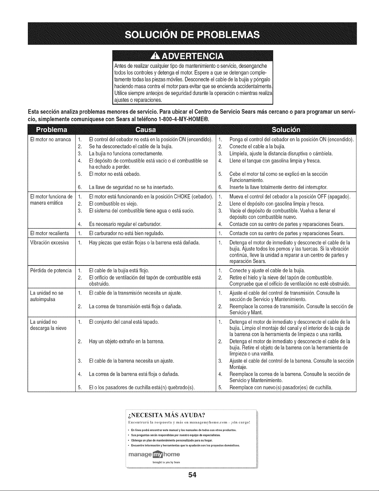
Antesde realizarcualquiertipo de mantenimientoo servicio,desenganche
todos loscontrolesy detengael motor.Esperea que se detengancomple-
tamentetodas laspiezasm6viles.Desconecteel cablede la bujiay p6ngalo
haciendomasacontrael motorpara evitarquese enciendaaccidentalmente.
Utilicesiempreanteojosde seguridaddurantela operaci6no mientrasrealiza
ajusteso reparaciones.
Esta seceibn analiza problemas menores de servieio. Para ubiear el Centro de
eio, simplemente eomuniquese con Sears al tel6fono 1-800-4-1VlY-HOME®.
Elmotor no arranca 1. El control del cebador no esta en la posicidn ON (encendido).
2. Se ha desconectado el cable de la buj[a.
3. ka bujia nofunciona correctamente.
4. Eldepdsitode combustibleestfi vado o el combustiblese
ha echadoa perder.
5. Elmotor no estacebado.
6. La Ilavede seguridadno se ha insertado.
Elmotorfuncionade 1. El motorestafuncionandoen la posici6nCHOKE(cebador).
maneraerratica 2. Elcombustiblees viejo.
3. Elsistemadel combustibletiene aguao estasucio.
4. Es necesarioregularel carburador.
Elmotorrecalienta 1. Elcarburadorno est,.bien regulado.
Vibraci6nexcesiva 1. Haypiezasque estanfiojas o la barrenaestadaSada.
P_rdidade potencia 1. El cablede la bujia est,. flojo.
2. Elorificio de ventilaci6ndel tap6n de combustibleesta
obstruido.
La unidad no se 1. Elcable de latransmisi6nnecesitaun ajuste.
autoimpulsa
2. La correade transmisi6nest_.flojao daSada.
1. Elconjuntodel canalesta tapado.
ServieioSearsm_s eereanoo paraprogramarun servi-
1. Pongael controldel cebador en la posici6nON (encendido).
2. Conecteel cablea la bujia.
3. Limpiela,ajustela distanciadisruptivao cambiela.
4. Lleneeltanque con gasolinalimpiay fresca.
5. Cebeel motortal como se explic6en lasecci6n
Funcionamiento.
6. Insertela Ilavetotalmentedentro del interruptor.
1. Muevaelcontrol del cebadora la posici6nOFF(apagado).
2. Lleneel dep6sitocongasolina limpiayfresca.
3. Vacie el dep6sitode combustible.Vuelvaa Ilenarel
dep6sitocon combustiblenuevo.
Contactecon sucentrode partesy reparacionesSears.
4,
1. Contactecon sucentrode partesy reparacionesSears.
1. Detengael motordeinmediatoy desconecteel cablede la
bujia.Ajustetodos los pernosy las tuercas.Si lavibraci6n
continOa,Ilevela unidad a reparara un centrode partesy
reparaci6nSears.
1. Conectey ajusteel cablede labujia.
2. Retireel hielo y la nievedel tap6nde combustible.
Cornpruebequeel orificiode ventilaci6nno est_ obstruido.
1. Ajusteel cabledel control de transmisi6n.Consultela
secci6nde Servicioy Mantenimiento.
2. Reemplacelacorrea de transmisi6n.Consultela secci6nde
Servicioy Mant.
La unidad no 1.
descarga la nieve
2. Hayun objeto extraSoen la barrena.
3. Elcable de la barrenanecesitaun ajuste.
4. La correade la barrenaestafioja o daSada.
5. Elo lospasadoresde cuchilla esta(n) quebrado(s).
Detengael motorde inmediatoy desconecteel cablede la
bujia.Limpieel montajedel canaly el interiorde lacaja de
labarrenacon la herramientade limpiezao unavarilla.
2. Detengael motordeinmediatoy desconecteel cablede la
bujia.Retireelobjeto de la barrenacon la herramientade
limpiezao unavarilla.
3. Ajusteel cabledel control de la barrena.Consultela secci6n
Montaje.
4. Reemplacelacorrea de la barrena.Consultelasecci6nde
Servicioy Mantenimiento.
5. Reemplacecon nuevo(s)pasador(es)de cuchilla.
i,NECESITA MAS AYUDA?
* En linea podr_ encontrar este maaual y los manuales de todos sus otros productos.
* Sus pregui_tas ser_n respondidas per nuestro equipo de especialistas.
Obtenga un plan de mantenimie_to personalizado para su hogar.
Encuelttre informaci6n y herramientas que Io ayudar_n con los proyectos dom6sticos.
54

55
MTD CONSUMER GROUP, iNC. (MTD), el Bordo de Recursos de Aire de California (CARB)
y la Agencia de Protecci6n Medioambiental de Estados Unidos (U. S. EPA)
Declaraci6n de Garantia del Sistema de Control de Emisiones
(Derechos y obligaciones del propietario seg_n la garantia contra defectos)
LACOBERTURADESISTEMADECONTROLDEEMISIONES APLICABLEA MOTORESCERTIFICADOSCOMPRADOSENCALIFORNIA
EN2005 Y A PARTIRDE ENTONCES,QUESON USADOSEN CALIFORNIA,Y HASTAANO2005DE MODELOCERTIFICADOY MOTORES
POSTERIORESQUESON COMPRADOSY USADOSENOTRAPARTEEN LOSESTADOSUNIDOS.
Californiayen otraparteen la Coberturade Garantiade DefectosdeControlde Emisi6nde los EstadosUnidos
El Bordode Recursosde Airede California(CARB),la U. S. EPAy MTDsecomplacenenexplicarla garantiadel sistemade controldeemisiones
de su motorparaequipotodo terreno,modelo,aSo2005y versionesposteriores.En California,los nuevosmotorespequeSospara equipotodo
terrenose debendise5ar,fabricary equiparparacumplirconest_.ndaresde antinieblat6xicade estados.Enotraparteen los EstadosUnidos,
el nuevonocamino,motoresde ignici6ndechispacertificadosparaelmodelo2005 y m_.starde,debeencontrareljuegode est_.ndaressimilar
adelantepor los EstadosUnidos.EPA.MTDdebe garantizarel sistemadecontrolde emisionesdesu motorpor elperiodode tiempoindicadom&s
abajo,siemprey cuandono hayaexistidousoincorrecto,negligencianimantenimientoinadecuadode su motorpequeBoparaequipo todoterreno.
El sistemade controlde emisionespuedeincluirpiezascomo,porejemplo,el carburador,sistemadeinyecci6ndecombustible,el sistemade
encendido,el catalizador,losdep6sitosde combustible,abastecede combustiblelineas, gorrasde combustible,v&lvulas,latas,filtros,mangueras
devapor,abrazaderas,conectoresy otroscomponentesrelacionadosconlas emisiones.
Dondeexistaunacondici6ncubiertapor la garantia,MTDreparar&su motor pequeBopara equipotodoterrenosincostoalgunoincluyendoel
diagn6stico,laspiezasy la manode obra.
COBERTURA DE LA GARANTJA DEL FABRICANTE:
Estesistemade controlde emisionesse garantizapor el t@rminode dos a5os.Si algunapiezade su motorrelacionadacon lasemisioneses
defectuosa,MTD reparar&o sustituir&dichapieza.
RESPONSABJLIDADES DEL PROPIETARIO SEGUN LA GARANTJA:
Comopropietariode un motorpequeSode equipotodoterreno,ustedes responsablede realizarel mantenimientonecesarioquefigura en el
manualdel propietario.MTDle recomiendaqueconservetodoslos recibosque cubrenlos serviciosde mantenimientodel motorpeque5opara
equipotodoterreno,noobstanteIo cual MTDnopodr&denegarel cumplimientodela garantiaQnicamentepor la falta de reciboso porsu imposibi-
lidadde asegurarquese realizar_.ntodos los serviciosde mantenimientoprogramado.
Comopropietariodel motorpeque5oparaequipotodo terreno,sinembargo,ustedtambi@ndebesaberque MTDpuededenegarla coberturadela
garantiasi su motorpeque5oparaequipotodoterrenoo unapiezadel mismofallandebidoa usoincorrecto,negligencia,mantenimientoindebido
oa modificacionesnoaprobadas.
Ustedes responsablede presentarlacortadoradecespedal centrode distribuci6no de mantenimientode MTDCONSUMERGROUP,INC.tan
prontocomoaparecierael problem& Lasreparacionescubiertaspor la garantfasedebenIlevara cabo en un lapsorazonableque noexcedade
30dias.Si desearealizaralgunaconsultacon respectoa la coberturade lagarantia,debeponerseencontactocon su distribuidorlocalde MTD.
Paracomunicarseconla LineadeAsistenciaal Clientede Distribuidoresde MTD,Ilameal nQmero(877)282-8684.
REQUERJMJENTOS DE GARANTJA SOBRE DEFECTOS PARA MOTORES PEQUENOS DE EQUJPO TODO TERRENO
DE 1995YVERSJONES POSTERJORES:
Estasecci6nse aplicaa motorespeque5osde equipotodo terrenode 1995y versionesposteriores.Elperiododegarantiacomienzaa partirde la
fechaen queel motoro elequiposeentreganal compradorfinal.
(a)Coberturade la garantiacontraemisionesgenerales
MTDgarantizaal compradorfinaly a cada compradorsubsiguientequeel motor:
(1)hasido diseSado,construidoy equipadode maneraquecumplacontodaslas regulacionesvigentesadoptadasporel Departamentode los
RecursosdeAire en virtud a suautoridadconferidaen los capitulos1y 2, Parte5, Divisi6n26del C6digode Saludy Seguridad;y
(2)est,. librede defectosen los materialesyen la manode obraquecausenlafalla deunapiezabajo garantiaque seaid@nticaentodoslos
aspectosmaterialesa lapiezacomo aparecedescriptaen laaplicaci6ndel fabricantedel motorparacertificaci6npor unperiododedos a5os.
Lb/Lagarantiasobre piezasrelacJonadasconemisJonesse interpretar_,de la sJguientemanera:
(1)Cualquierpiezacubiertapor garantiaquenoest@programadaparasu reemplazosegQnel mantenimientorequeridoenlas instrucciones
escritasdela Subsecci6n(c) debe estar garantizadapor un periodode garantiadefinidoen la Subsecci6n(a)(2). Si la piezafalladurante
el periododecoberturadela garantia,la mismaser_.reparadao reemplazadapor MTD de acuerdocon laSubsecci6n(4)a continuaci6n.
Cualquierpiezareparadao reemplazadasegQnlagarantiasegarantizarB,por el restodelperiodode garantia.
(2) Cualquierpiezacubiertaporgarantiaque est@programadasoloparainspecci6nregularen las instruccionesescritasde la Subsecci6n
(c) debeestargarantizadaporun periododegarantiadefinidoenla Subsecci6n(a) (2). Unadeclaraci6nen dichasinstruccionespor escrito
alefectode "reparaci6no reemplazosegQnseanecesario"no reducir_,elperiodode coberturade la garantia.Cualquierpiezareparadao
reernplazadasegQnlagarantiasegarantizar_,porelrestodelperiododegarantia.
(3) Cualquierpiezagarantizadaqueest_prograrnadaparareernplazosegQnelrnantenirnientorequeridodeconforrnidadconlasinstruc-
clonesescritasdelaSubsecci6n(c)segarantizaporelperiododetiernpoanterioralaprirnerafechadereernplazoprograrnadaparaesa
pieza.Silapiezafallaantesdelprimerreernplazoprogramatic,larnisrnaser_.reparadaoreernplazadaporMTDdeacuerdoconlaSubsecci6n
(4)acontinuaci6n.Cualquierpiezareparadaoreernplazadabajogaranfiasegarantizar_,porelrestodelperiodoanterioralprimerreernplazo
programaticpuntualparaesapieza.
(4)Lareparaci6noelreernplazodecualquierpiezagarantizadadeconforrnidadconlasdisposicionesdelagaranfiaqueaquiseestipulase
deberealizarenuncentrodegaranfiasincostoalgunoparaelpropietario.
(5)SinperjuiciodelasdisposicionesdelaSubsecci6n(4)anterior,losserviciosoreparacionescubiertosporlagaranfiadebensersurnin-
istradosportodosloscentrosdedistribuci6ndeMTDquetenganlafranquiciapararealizarreparacionesyrnantenirnientoalosrnotoresen
cuesti6n.
(6)ElpropietarionodebeafrontarningQncargoparatrabajosdediagn6sticoqueIlevenalaconclusi6ndequeunapiezabajogaranfiapresenta
efectivarnentedefectos,siernpreycuandodichodiagn6sticoseaIlevadoacaboenuncentrocubiertoporlagarantia.
(7)Elfabricantedelmotoresresponsableporda_oscausadosaotroscornponentesdernotoresderivadosdelafallabajogaranfiadecualquier
piezagarantizada.
(8)DurantetodoelperiododegaranfiadelmotordefinidoenlaSubsecci6n(a)(2),MTDrnantendr_,unsurninistrodepiezascubiertaspor
garantiasuficienteparasatisfacerladernandaesperadaparatalespiezas.
(9)Cualquierpiezadereernplazosepodr_,usarparaelcurnplirnientodelrnantenirnientooreparacionesbajogaranfia,ysesurninistrar_,sin
cargoalpropietario.Dichousonoreducir_,lasobligacionesdegarantiadeMTD.
(10)Nosepodr_.nusarpiezasadicionalesnirnodificadasquenoest_nexentasdeacuerdoconelDepartarnentodelosRecursosdelAire(Air
ResourcesBoard).Elusodepiezasadicionalesornodificadasnoexentasser_.causasuficienteparaanularunreclarnobajogaranfiarealizado
deacuerdoconestearticulo.Elfabricantedelmotornotendr_,responsabilidad,enconforrnidadconestearticulo,degarantizarfallasdepiezas
garantizadasquefuerencausadasporelusodeunapiezanoexentaadicionalornodificada.
.(c)MTDincluir_,una copiade lasiguientelistade piezasbajo garantiacontraernisionescon cadanuevomotor,utilizandolas partesde la lista
a_plicablesal motor.
(1)Sisternadernedici6ndecombustible
• Sisternade rnejorapara inicioenfrio (cebadosuave)
• Carburadory cornponentesinternos
• Bornbade combustible
• Dep6sitode combustible
(2) Sisternade inducci6nde aire
• Filtrode aire
• Colectorde entrada
(3) Sisternade encendido
• Bujia(s)
• Sisternadeencendidopor magneto
(4)Sisternadeescape
• Catalizador
• SAI (v_Jvulade Ca_a)
(5) Cornponentesvariosutilizadosen el sisternaanterior
• V_Jvulase interruptoresde vado, ternperatura,posici6nsensiblesal tiernpo
• Conectoresy rnontajes
(6)Controlde Evaporative
• Manguerade CombustiblecertificadaparaARB evaporativeernisi6nde 2006.
• Abrazaderasde Manguerade Combustible
• Gorrade combustibleatada
• Latade carb6n
• Lineasdevapor
GD0C-100174Rev.B
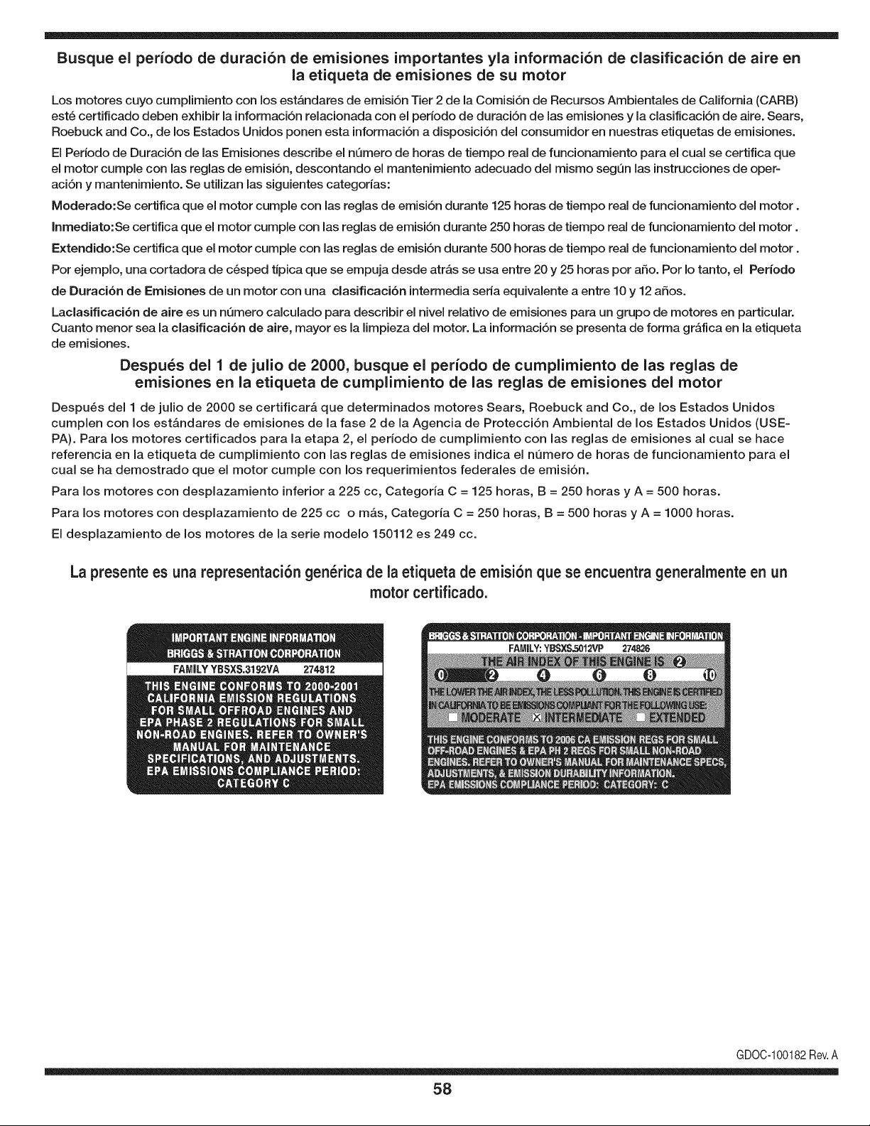
Busque el periodo de duraci6n de emisiones importantes yla informaci6n de clasificaci6n de aire en
la etiqueta de emisiones de su motor
Los motores cuyo cumpiimiento con los estAndares de emisi6n Tier 2 de la Comisi6n de Recursos Ambientales de California (CARB)
est6 certificado deben exhibir la informaci6n relacionada con el perJodo de duraci6n de las emisiones y la clasificaci6n de aire. Sears,
Roebuck and Co., de los Estados Unidos ponen esta informaci6n a disposici6n deJ consumidor en nuestras etiquetas de emisiones.
El Periodo de Duraci6n de las Emisiones describe el nQmero de horas de tiempo real de funcionamiento para el cual se certifica que
el motor cumple con las reglas de emisi6n, descontando el mantenimiento adecuado deJ mismo segQn las instrucciones de oper-
aci6n y mantenimiento. Se utilizan las siguientes categorias:
Moderado:Se certifica que el motor cumpie con las reglas de emisi6n durante 125 horas de tiempo real de funcionamiento deJ motor.
Inmediato:Se certifica que el motor cumple con las reglas de emisi6n durante 250 horas de tiempo real de funcionamiento deJ motor.
Extendido:Se certifica que el motor cumple con las reglas de emisi6n durante 500 horas de tiempo real de funcionamiento deJ motor.
Por ejemplo, una cortadora de c6sped tJpica que se empuja desde atrAs se usa entre 20 y 25 horas por afio. Por Io tanto, el Periodo
de Duraci6n de Emisiones de un motor con una clasificaci6n intermedia seria equivalente a entre 10 y 12 afios.
Laclasificaci6n de aJre es un nQmero calculado para describir eJnivel reiativo de emisiones para un grupo de motores en particular.
Cuanto menor sea Jaclasificaci6n de aire, mayor es JaJimpieza deJ motor. La informaci6n se presenta de forma gr&fica en Jaetiqueta
de emisiones.
Despu_s del 1 de julio de 2000, busque el periodo de cumplimiento de las reglas de
emisiones en la etiqueta de cumplimiento de las reglas de emisiones del motor
Despu_s deJ 1 de julio de 2000 se certificar_, que determinados motores Sears, Roebuck and Co., de los Estados Unidos
cumpien con los estAndares de emisiones de la fase 2 de la Agencia de Protecci6n Ambiental de los Estados Unidos (USE-
PA). Para los motores certificados para la etapa 2, el periodo de cumpiimiento con las reglas de emisiones al cual se hace
referencia en la etiqueta de cumpiimiento con las reglas de emisiones indica el nQmero de horas de funcionamiento para el
cuaJ se ha demostrado que el motor cumpie con los requerimientos federales de emisi6n.
Para los motores con desplazamiento inferior a 225 cc, Categoria C = 125 horas, B = 250 horas y A = 500 horas.
Para los motores con desplazamiento de 225 cc o mAs, Categoria C = 250 horas, B = 500 horas y A = 1000 horas.
El despiazamiento de los motores de la serie modelo 150112 es 249 cc.
La presente es una representaci6n gen_rica de la etiqueta de emisi6n que se encuentra generaimente en un
motor certificado.
GDOC-100182Rev.A
58
Felicitacionespor haberrealizadounaadquisici6ninteligente.El
productoCraftsman@queha adquiridoest_ dise_adoy fabricado
parabrindarrnuchosa_osde funcionarnientoconfiable.Perocorno
todoslos productosa vecespuederequerirde reparaciones.Esen
esernornentocuandoel disponerde unAcuerdode protecci6npara
reparacionesle puedeahorrardineroy problernas.
A continuaci6nsedetallanlos puntosincluidosen el Acuerdo:
• Servicio experto prestadopor nuestros10,000especialistasen
reparacionesprofesionales
• Servicio ilirnitadosin cargopara laspiezasy la rnanode obra en
todaslas reparacionescubiertas
• Reernplazodel productohasta1500d61aressi no es posible
repararel productocubierto
• Descuentode 10%del precionormaldel servicioy delas piezas
relacionadascon el rnisrnoqueno est_ncubiertasporel acuerdo;
adern&s,10%del precionormalde la verificaci6nde rnanten-
irnientopreventivo
• Ayudar_pidapottel_fono- IoIlarnarnosResoluci6nR_pida- el
apoyotelef6nicode un Charnuscaal representante.Pienseen
nosotroscornoel manual"de undue_ohablador."
Unavezadquiridoel Acuerdo,puedeprograrnarel serviciocon
tan s61orealizarunaIlarnadatelef6nica.PuedeIlarnarencualquier
mornentodeldia o de la nocheo prograrnarun servicioen linea.
ElAcuerdode Protecci6nde Reparaci6nes una cornprasin riesgo.
Siustedanulaporalgunaraz6nduranteel periodode garantiade
producto,proporcionarernosun reernbolsoIleno.O,un reernbolso
prorrateadoen cualquiermornentodespu_sdelperiodode garantia
de productoexpira, iAdquieraboysu acuerdode protecci6npara
reparaciones!
Seaplican deterrninadaslirnitaciones y exclusiones.Paraobtener
inforrnaci6nadicional y preciosen los Estados UnidosIlarne al
1-800-827-6655.
El*Coverage en Canad_variaen algunosarticulos. Paradetalles
Ilenosla IlarnadaCharnuscaCanad_en 1-800-361-6665.
Servicio de instalaci6nde Sears
Sideseasolicitarla instalaci6nprofesionalde Searsde aparatos
dorn_sticos,dispositivosparaabrir portones,calentadoresde agua
y otrosarficulosdorn_sticosirnportantes,en los EstadosUnidoso
Canad_Ilarneal 1-800-4-MY-HOME®.
59

Your Home
For expert troubleshooting and home solutions advice:
www.managemyhome.com
For repair - in your home - of all major brand appliances,
lawn and garden equipment, or heating and cooling systems,
no matter who made it, no matter who sold it!
For the replacement parts, accessories and
owner's manuals that you need to do-it-yourself.
For Sears professional installation of home appliances
and items like garage door openers and water heaters.
1-800-4-MY-HOME ® (1-800-469-4663)
Call anytime, day or night (U.S.A. and Canada)
www.sears.com www.sears.ca
Our Home
For repair of carry-in items like vacuums, lawn equipment,
and electronics, call anytime for the location of your nearest
Sears Parts & Repair Service Center
1-800-488-1222 (U.S.A.) 1-800-469-4663 (Canada)
www.sears.com www.sears.ca
To purchase a protection agreement on a product serviced by Sears:
1-800-827-6655 (U.S.A.) 1-800-361-6665 (Canada)
Para pedir servicio de reparaci6n
a domicilio, y para ordenar piezas:
1-888-SU-HOGAR ®
(1-888-784-6427)
Au Canada pour service en fran£ais:
1-800-LE-FOYER M°
(1-800-533-6937)
www.sears.ca
® Registered Trademark / TMTrademark / SM Service Mark of Sears Brands, LLC
SM
® Marca Registrada / TMMarca de F&brica / Marca de Servicio de Sears Brands, LLC
MCMarque de commerce / MD Marque depos6e de Sears Brands, LLC © Sears Brands, LLC