Loading ...
Loading ...
Loading ...
6
WARRANTY
For more eective and safer operation and to
prolong the life of the heater, read the Owner’s
Guide and follow the instructions. Failure to properly
maintain the heater will void any warranty and may
cause the heater to function improperly.
LIMITED FIVE YEAR WARRANTY: Glen Dimplex
Americas will repair or replace any Intelligent Fan-
forced Heater found to be defective within five years
after the date of purchase.
These warranties do not apply:
1. Damage occurs to the product through improper
installation or incorrect supply voltage;
2. Damage occurs to the product through improper
maintenance, misuse, abuse, accident, or alteration;
3. The use of unauthorized accessories or unau-
thorized components constitutes an alteration and
voids all warranties. Refer to gdaheat.com or call
customer service at 888-346-7539 for list of autho-
rized accessories and components.
4. Glen Dimplex Americas’ warranty is limited to
repair or replacement.
5. In the event Glen Dimplex Americas elects to
replace any part of your product, the replacement
parts are subject to the same warranties as the
product. The installation of replacement parts does
not modify or extend the underlying warranties. Re-
placement or repair of any Glen Dimplex Americas
product or part does not create any new warranties.
If you believe your product is defective, please
contact Glen Dimplex Americas during the warranty
period, for instructions on how to have the repair or
replacement processed.
Parts and Service
Visit gdaheat.com/parts for information on where to
obtain parts and service.
To register your product, visit gdaheat.com/register
BLUE
RED
YELLOWBLACK
MOTOR
HEATING ELEMENT
HIGH-TEMPERATURE
SAFETY SHUTOFF
DIGITAL
THERMOSTAT
BLACK
BLACK/
WHITE
L1
L2
WHITE
RED
BLACK
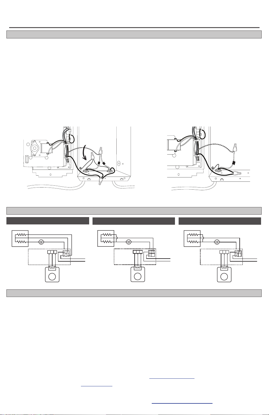
INTERNAL HEATER WIRING DIAGRAM
Figure 5
this set of wires from
the circuit breaker
additional
copper wire
connected here
to grounding
screw
MULTIPLE HEATERS ON ONE CIRCUIT BREAKER (240 or 208 volts only)
1. Route the electrical supply wire from the circuit breaker to heater #1. Remove two knockouts and
attach two sets of electrical supply wire with two cable clamp connectors (not included) leaving a mini-
mum of 6 inches wire lead—one set from the circuit breaker, the other set to heater #2 (See Figure 5).
2. The two supply ground wires in the wall can of heater #1 need to make a 3-wire connection with the
grounding screw. Attach a short copper ground wire to the grounding screw in the wall can. Connect
this wire and the two supply ground wires with a wire connector (not included). (See Figure 5).
3. For heater #1, connect each heater wire with one of the supply wires going to the circuit breaker, and
one of the supply wires going to heater #2. Each of the wires from heater #1 must have a 3-wire con-
nection. For heater #2, make the connections in the wall can as shown below.
More than one heater can be wired in parallel on the same circuit breaker (be sure to check national and
local codes for safety requirements). Additional electrical supply wire and cable clamp connectors are
required. The heaters must be in the same room.
Maximum amperage you can put on one circuit breaker is limited to 80% of the circuit breaker capacity.
this set of wires
from heater #1
heater #1
(back)
heater #2
(back)
this set of wires
to heater #2
After making all connections, go to Page 5 and proceed with STEP 4 Finish installation, number 4.
RED
YELLOWBLACK
MOTOR
HEATING ELEMENT
HIGH-TEMPERATURE
SAFETY SHUTOFF
DIGITAL
THERMOSTAT
BLACK
BLACK/
WHITE
L1
L2
WHITE
RED
BLACK
RED
YELLOWBLACK
MOTOR
HEATING ELEMENT
HIGH-TEMPERATURE
SAFETY SHUTOFF
DIGITAL
THERMOSTAT
BLACK
BLACK/
WHITE
L1
L2
ORANGE
RED
BLACK
CE168T 208 Volt
CE162T 240 Volt
CE163T Multi-Volt
INSTALLATION INSTRUCTIONS
Loading ...
Loading ...