Customer Service:
Phone: 888-346-7539 (from US or Canada)
Email: cs@glendimplexamericas.com
Assembled in USA
gdaheat.com
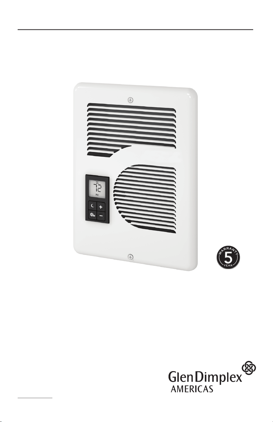
OWNER’S GUIDE
Thank you for your purchase! Question or problem? Let us solve it with a single
phone call, email or online chat! We’ll save you a trip back to the store!
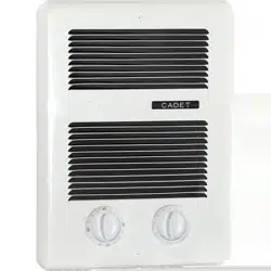
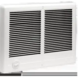
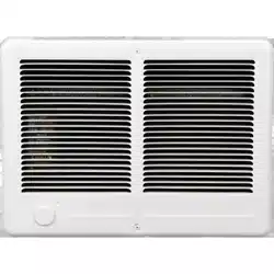
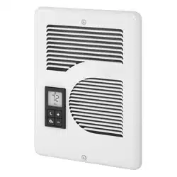
Intelligent fan-forced heater
2
SAVE THESE INSTRUCTIONS
1. Read all instructions before install-
ing or using this heater.
2. This heater is hot when in use. To
avoid burns, do not let bare skin
touch hot surfaces. Keep combus-
tible materials, such as furniture,
pillows, bedding, papers, clothes,
etc. and curtains at least 3 feet (0.9
meters) from the front of the heater
and keep them away from the sides.
3. Extreme caution is necessary
when any heater is used by or near
children or invalids and whenever
the heater is left operating and
unattended.
4. Do not operate any heater after it
malfunctions. Disconnect power
at service panel and have heater
inspected by a reputable electrician
before reusing.
5. Do not use outdoors.
6. To disconnect heater, turn control(s)
to o, and turn o power to heater
circuit at main disconnect panel.
7. Do not insert or allow foreign
objects to enter any ventilation or
exhaust opening as this may cause
an electric shock or fire, or damage
the heater.
8. To prevent a possible fire, do not
block air intakes or exhaust in any
manner.
9. A heater has hot and arcing or
sparking parts inside. Do not use
it in areas where gasoline, paint,
or flammable vapors or liquids are
used or stored.
10. Use this heater only as described
in this manual. Any other use not
recommended by the manufacturer
may cause fire, electric shock, or
injury to persons.
11. This heater must be installed in a
fixed, permanent location.
When using electrical appliances, basic precautions should always be followed
to reduce the risk of fire, electric shock, and injury to persons, including the
following:
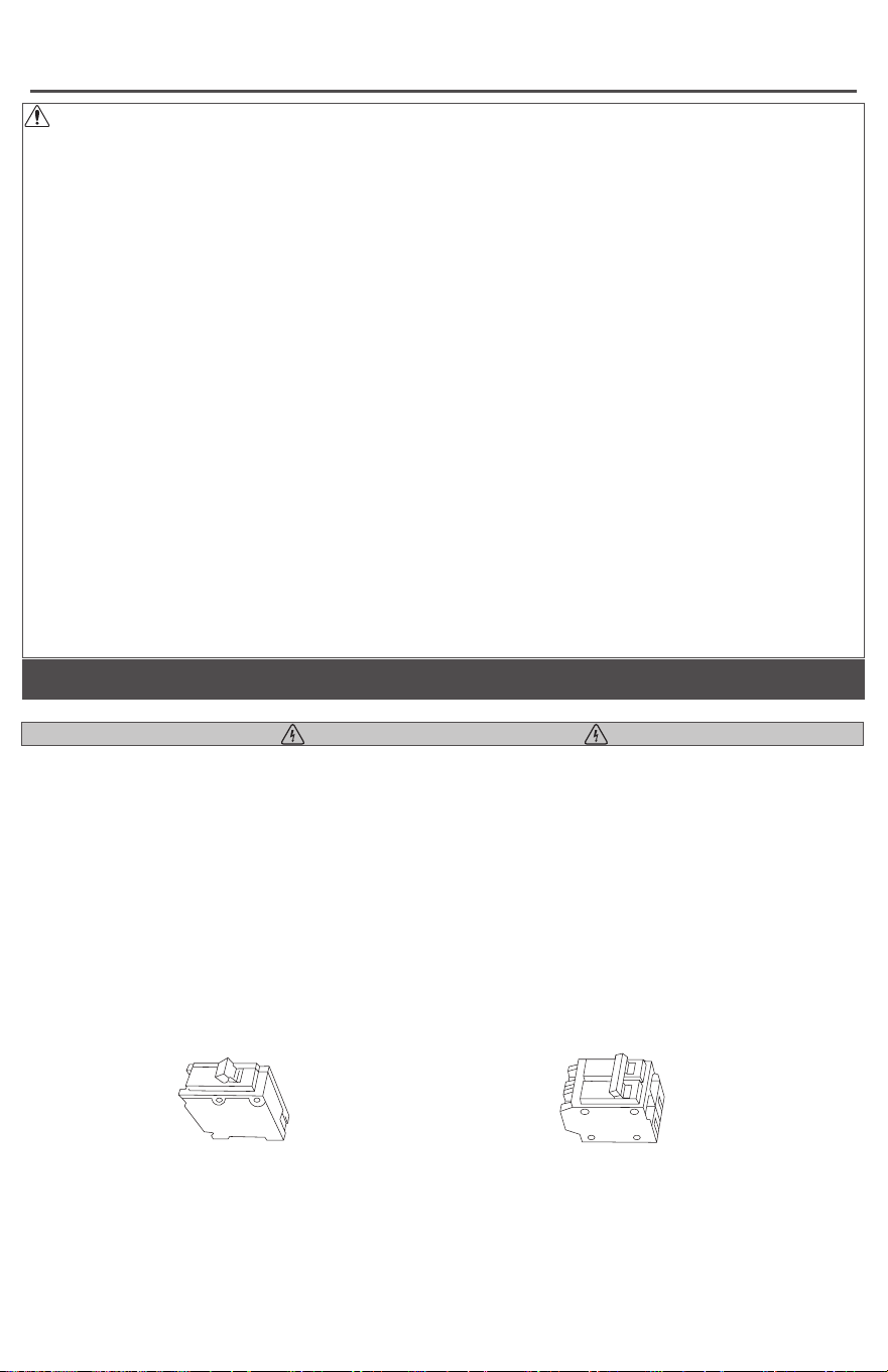
KNOW YOUR VOLTAGE!
120 volt
single-pole breaker
240 volt
double-pole breaker
If you are uncomfortable working with electricity, running electrical supply wire or
installing a circuit breaker, please consult a licensed electrician. Make sure power to
the heater is turned o at the main disconnect panel whenever doing any work on a
heater. Serious injury or electrocution can result from electric shock.
• CHECK YOUR BREAKER! If you’re replacing an existing heater, check the labels of
the old heater and use the same voltage.
Unanswered questions? Call our technical support team toll free at 888-346-7539
(from US or Canada)
WARNING: Connecting a heater to a voltage higher than what’s listed on its rating
label will destroy the heater and could start a fire. A heater will not heat properly
when connected to a voltage lower than what’s listed on its rating label.
IMPORTANT INSTRUCTIONS
• The multi-volt CE163T and CE083T heaters are equipped with a smart sensor that
will auto adjust to your voltage supply.
The CE162T can only be connected to 240 volts, and the CE168T can only be
connected to 208 volts.
3
TOOLS REQUIRED
Tape Measure
Straight and Phillips
Screwdrivers1½" Wood ScrewsWire Strippers Wire Connectors
½" Cable Clamp
Connector
Volt Meter
Drill and Drill Bits
Stud Finder
A multi-purpose tool or something to cut your existing drywall or gypsum board.
Z
I
R
C
O
N
®
®
Z
I
R
C
O
N
®
®
Z
I
R
C
O
N
®®
Z
I
R
C
O
N
®
®
Z
I
R
C
O
N
®®
Z
I
R
C
O
N
®
®
Hammer
Z
I
R
C
O
N
®
®
Z
I
R
C
O
N
®®
Z
I
R
C
O
N
®
®
Z
I
R
C
O
N
®®
1. All electrical work and materials must
comply with the National Electric
Code (NEC), the Occupational Safe-
ty and Health Act (OSHA), and all
state and local codes.
2. Use copper conductors only.
3. DO NOT install the heater directly
above bathtub or sink. DO NOT
install in shower stall area. It is
recommended to install your heater
at least 2 feet (61 cm) away to
prevent contact with water.
4. Heater must be installed in a wall
can:
Model CE - wall can model CC or
CCSM
5. DO NOT install the heater in a floor,
in the ceiling, below a towel bar,
behind a door, or anywhere the air
discharge may be blocked in any
manner.
6. To reduce the risk of fire, do not
store or use gasoline or other flam-
mable vapors and liquids in the vi-
cinity of the heater.
7. Connect grounding lead to
grounding screw provided. Keep
all foreign objects out of heater.
8. Electric heaters must be installed
on a circuit dedicated to electric
heaters, they cannot share a circuit
with outlets, lights, or other appli-
ances.
10. CAUTION-High temperature, risk
of fire, keep electrical cords, drap-
ery, furnishings, and other combus-
tibles at least 3 feet (0.9 m) from
the front of the heater and away
from the side and rear.
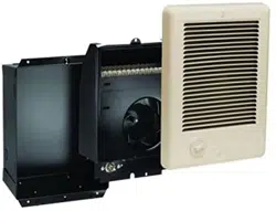
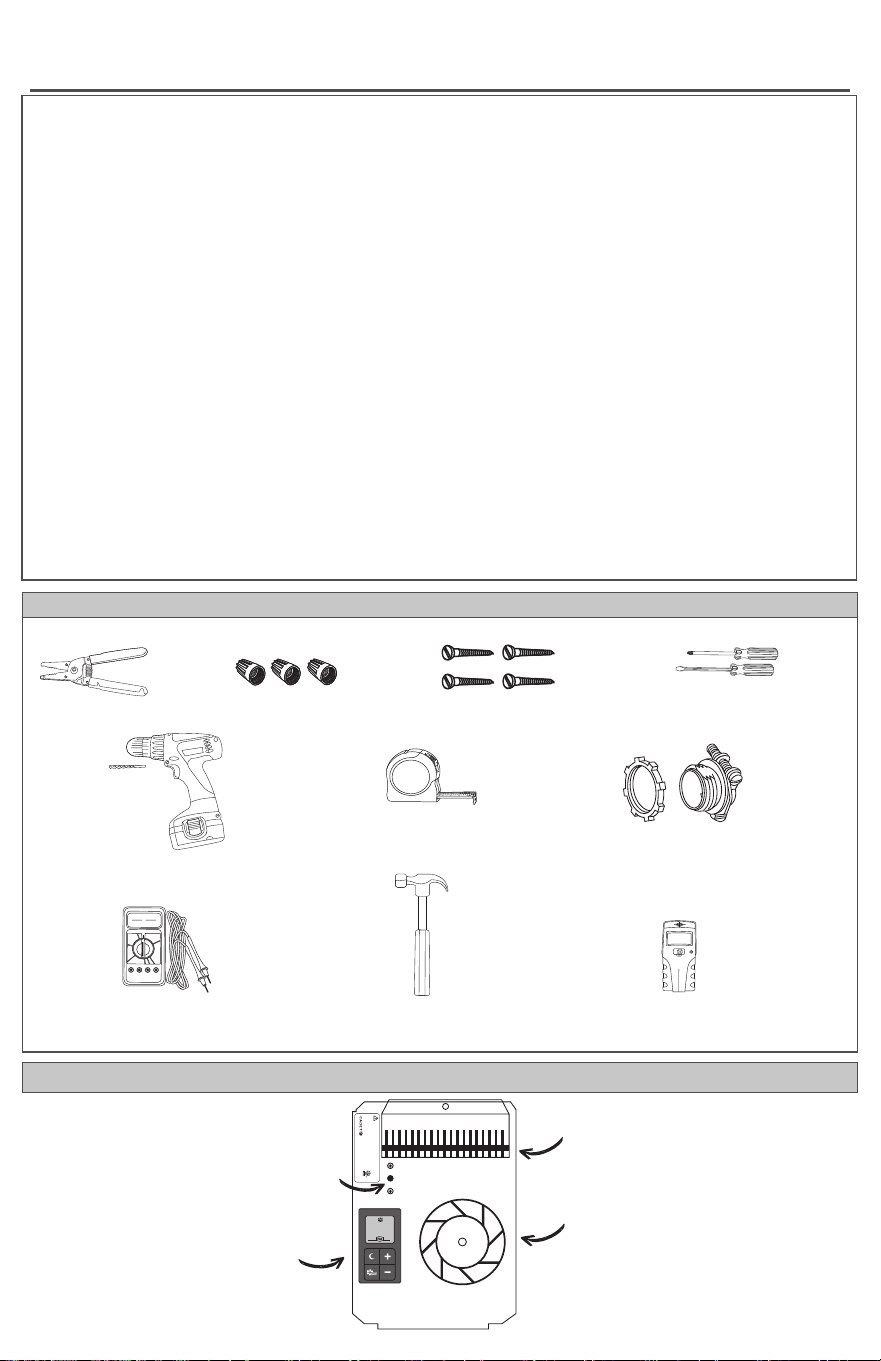
PARTS OF YOUR HEATER
Model:
Volts:
Watts:
WARNING! TO AVOID ELECTRICAL SHOCK
Disconnect power at circuit breaker before servicing.
Do not operate without grill.
cadetheat.com
Vancouver, WA
Mfg Date:
Before pushing
RESET button see
Owner’s Guide
for display fault
codes and other
troubleshooting
information.
3108579
conforms
to UL STD
2021
072xxx
73
built-in digital
thermostat
heater element
fan and
motor
high-temperature
safety shuto
INSTALLATION INSTRUCTIONS
4
• Verify power has been turned o before starting any work!
• The Intelligent Fan-forced Heater can only be mounted with the element up. It cannot be mounted in
the ceiling or in the floor. For multiple heater wiring, see page 6.
• For cleaner performance and longer heater life, install your heater 12 inches from the floor.
• All models can be installed to be Americans with Disabilities Act (ADA) compliant. Check your state
and local requirements.
• A wall thermostat cannot be used with this heater.
• The wall can label arrows show the correct mounting orientation (arrows must point up).
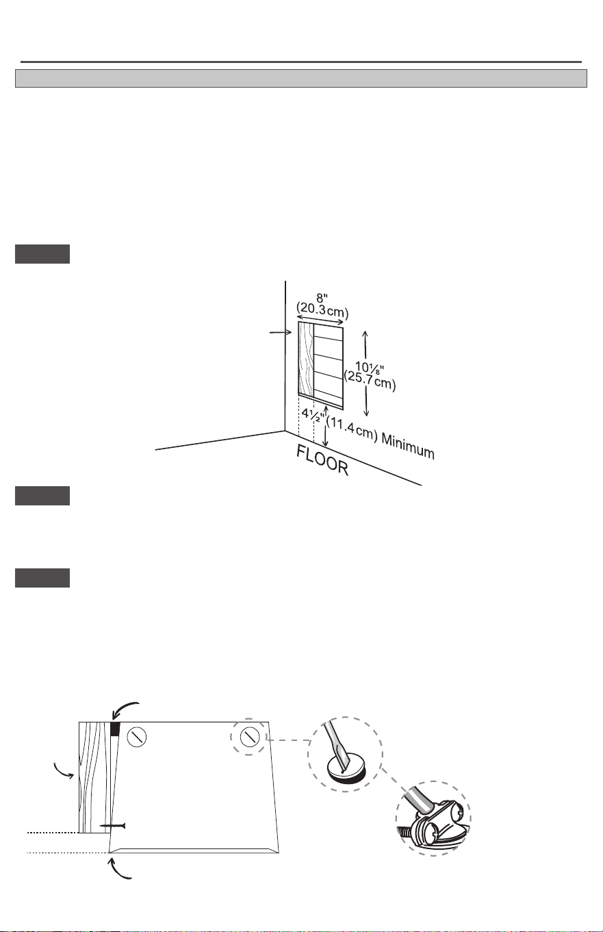
If you haven’t installed drywall yet, make sure the front of the wall can extends beyond the front edge of
the wall stud to match the drywall depth (See Figure 2).
If you already have drywall installed, place the can into the cutout so the front is flush with the drywall.
Fasten the wall can to the stud with two screws through holes provided in the wall can (See Figure 2). As
an option, the foam pad provided may be attached to the side of the wall can to square the wall can to the
stud.
STEP 3
Mount the wall can
STEP 1
Cut a hole in the wall next to a wall stud
PARED
ADYACENTE
¾"
(1.9 cm)
Min.
ADJACENT
WALL
¾"
(1.9 cm)
Minimum
attach foam pad here
STEP 2
Locate or route electrical supply wires
Route the electrical supply wire from the circuit breaker to the heater location.
Remove a knockout from the wall can and attach the supply wire with a cable clamp connector (not
included) leaving a minimum of 6 inches wire lead (See Figure 2).
Figure 2
View from top of wall can
If you haven’t installed drywall yet, skip this step.
TIPS BEFORE YOU BEGIN
Figure 1
front of wall can extends beyond front
edge of wall stud to match drywall depth
drywall
wall
stud
twist with screwdriver
to remove one of the
knockouts
attach supply wire
with a cable clamp
connector
fasten with 2
wood screws
INSTALLATION INSTRUCTIONS
5
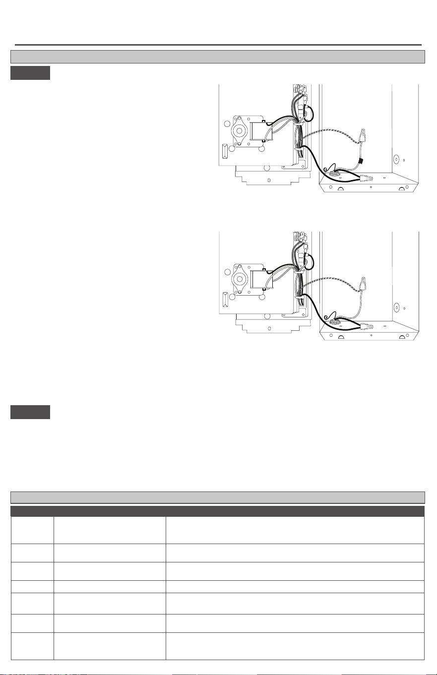
INSERT THE HEATER ASSEMBLY IN THE WALL CAN
Wire connections
STEP 4
Install grill
STEP 5
Attach grill with screws provided. Turn electrical power back on at the main disconnect panel.
Wait 10 to 15 seconds for heater to power up before pushing any buttons. After a few seconds, if the
heater has been properly installed, the display will flash and show room temperature. The default
temperature setting in HEAT mode is 70
˚
F (21.1
˚
C).
Proceed to OPERATING INSTRUCTIONS.
1. Your heater has two connection wires on the
side. Your supply wire has two connection wires
and a supply ground wire.
A. Connect supply ground wire to grounding
screw in wall can (See Figures 3 and 4).
B. Connect one supply wire to one heater
wire with a wire connector (not included).
For 240 or 208 volts, it doesn’t matter
which heater wire. Both supply wires
(black and white) are hot. Wrap supply
(white) wire with black tape to identify it as
hot (Figure 3).
For 120 volts, connect the neutral (white)
supply wire to the black and white striped
heater wire (Figure 4).
C. Connect the remaining supply wire to the
remaining heater wire with a wire connector
(not included) (See Figures 3 and 4).
2. Insert the bottom edge of the heater assem-
bly into the D-shaped tabs at the bottom of the
wall can.
3. Push all wires back into the bottom of the
wall can. Make sure connections are tight and
none of the wires are caught between the motor
and the wall can, or pinched between the side
of the heater and the wall can.
Figure 3
240 Volt
4. Attach the heater assembly at top of the wall can with screw provided. Align digital display with grill
cutout before tightening.
wall can
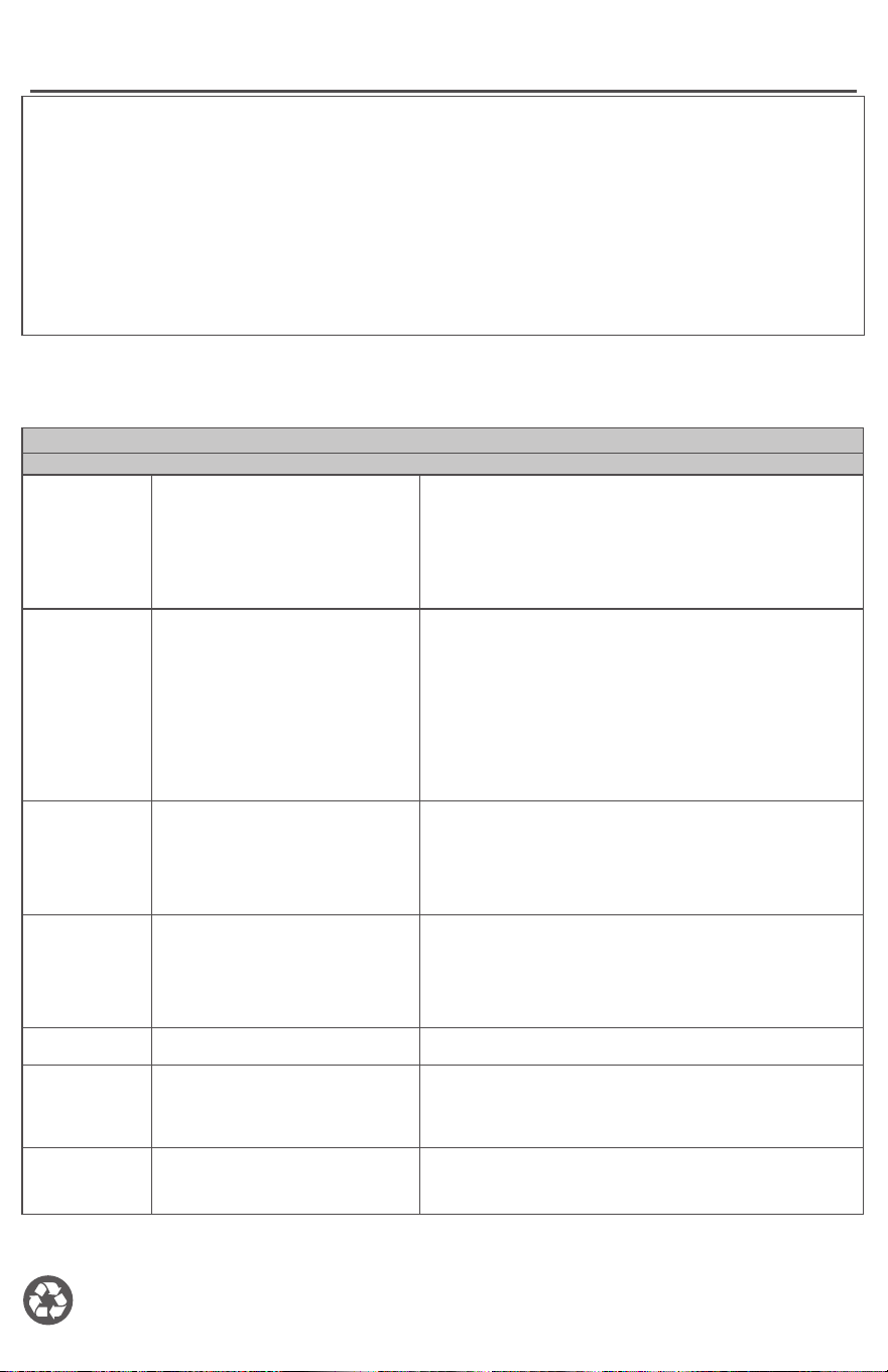
DISPLAY PROBLEM SOLUTION
No
Display
No power, internal control
faulty
Check that power is being supplied to heater. If operating on
generator power, confirm generator setting; if display still doesn’t
turn on, control is faulty. Replace heater assembly.
F1
Grill is interfering with
display buttons
Turn power o at main disconnect panel, realign grill. Turn power
back on at main disconnect panel.
F4
1. Line voltage is too low
2. Loose wire connections
1. Clears automatically when line voltage returns to normal.
2. Check wire connections.
F6
Line voltage is too high Clears automatically when line voltage returns to normal.
F8
Internal control fault
Disconnect power, reconnect power. If F8 code returns, control is
faulty. Replace heater assembly.
FF
Temperature
is
below
0˚F
(-17.8˚C), too low to display
Clears automatically when temperature is 0˚F (-17.8˚C) or above.
FA
Line voltage is too low
Double check voltage supply matches heater voltage rating. A
CE168T can only be connected to 208 volts, and a CE162T can
only be connected to 240 volts.
FAULT CODES
Figure 4
120 Volt
A
B
C
A
B
C
wall can
INSTALLATION INSTRUCTIONS
6
WARRANTY
For more eective and safer operation and to
prolong the life of the heater, read the Owner’s
Guide and follow the instructions. Failure to properly
maintain the heater will void any warranty and may
cause the heater to function improperly.
LIMITED FIVE YEAR WARRANTY: Glen Dimplex
Americas will repair or replace any Intelligent Fan-
forced Heater found to be defective within five years
after the date of purchase.
These warranties do not apply:
1. Damage occurs to the product through improper
installation or incorrect supply voltage;
2. Damage occurs to the product through improper
maintenance, misuse, abuse, accident, or alteration;
3. The use of unauthorized accessories or unau-
thorized components constitutes an alteration and
voids all warranties. Refer to gdaheat.com or call
customer service at 888-346-7539 for list of autho-
rized accessories and components.
4. Glen Dimplex Americas’ warranty is limited to
repair or replacement.
5. In the event Glen Dimplex Americas elects to
replace any part of your product, the replacement
parts are subject to the same warranties as the
product. The installation of replacement parts does
not modify or extend the underlying warranties. Re-
placement or repair of any Glen Dimplex Americas
product or part does not create any new warranties.
If you believe your product is defective, please
contact Glen Dimplex Americas during the warranty
period, for instructions on how to have the repair or
replacement processed.
Parts and Service
Visit gdaheat.com/parts for information on where to
obtain parts and service.
To register your product, visit gdaheat.com/register
BLUE
RED
YELLOWBLACK
MOTOR
HEATING ELEMENT
HIGH-TEMPERATURE
SAFETY SHUTOFF
DIGITAL
THERMOSTAT
BLACK
BLACK/
WHITE
L1
L2
WHITE
RED
BLACK
INTERNAL HEATER WIRING DIAGRAM
Figure 5
this set of wires from
the circuit breaker
additional
copper wire
connected here
to grounding
screw
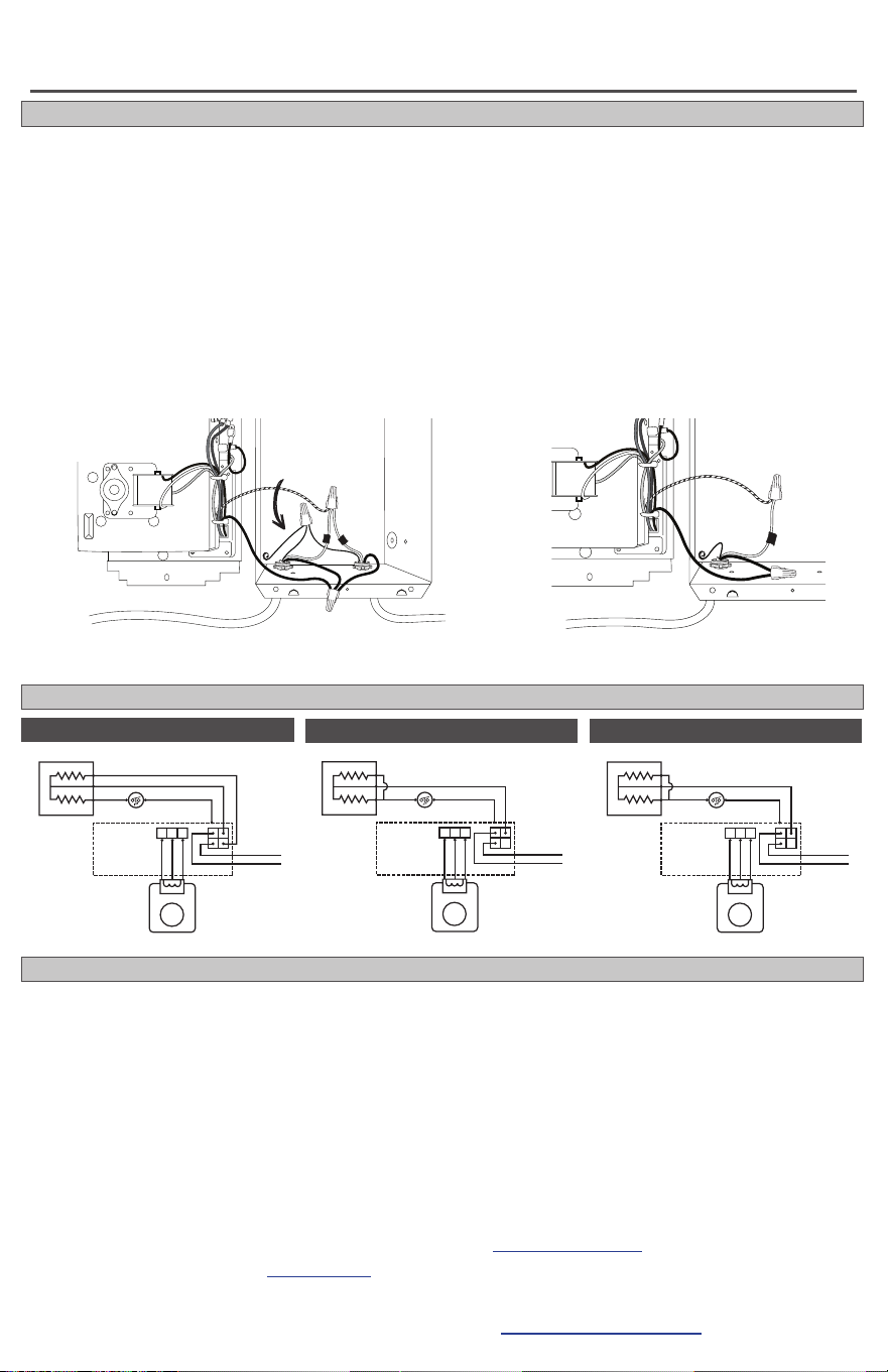
MULTIPLE HEATERS ON ONE CIRCUIT BREAKER (240 or 208 volts only)
1. Route the electrical supply wire from the circuit breaker to heater #1. Remove two knockouts and
attach two sets of electrical supply wire with two cable clamp connectors (not included) leaving a mini-
mum of 6 inches wire lead—one set from the circuit breaker, the other set to heater #2 (See Figure 5).
2. The two supply ground wires in the wall can of heater #1 need to make a 3-wire connection with the
grounding screw. Attach a short copper ground wire to the grounding screw in the wall can. Connect
this wire and the two supply ground wires with a wire connector (not included). (See Figure 5).
3. For heater #1, connect each heater wire with one of the supply wires going to the circuit breaker, and
one of the supply wires going to heater #2. Each of the wires from heater #1 must have a 3-wire con-
nection. For heater #2, make the connections in the wall can as shown below.
More than one heater can be wired in parallel on the same circuit breaker (be sure to check national and
local codes for safety requirements). Additional electrical supply wire and cable clamp connectors are
required. The heaters must be in the same room.
Maximum amperage you can put on one circuit breaker is limited to 80% of the circuit breaker capacity.
this set of wires
from heater #1
heater #1
(back)
heater #2
(back)
this set of wires
to heater #2
After making all connections, go to Page 5 and proceed with STEP 4 Finish installation, number 4.
RED
YELLOWBLACK
MOTOR
HEATING ELEMENT
HIGH-TEMPERATURE
SAFETY SHUTOFF
DIGITAL
THERMOSTAT
BLACK
BLACK/
WHITE
L1
L2
WHITE
RED
BLACK
RED
YELLOWBLACK
MOTOR
HEATING ELEMENT
HIGH-TEMPERATURE
SAFETY SHUTOFF
DIGITAL
THERMOSTAT
BLACK
BLACK/
WHITE
L1
L2
ORANGE
RED
BLACK
CE168T 208 Volt
CE162T 240 Volt
CE163T Multi-Volt
INSTALLATION INSTRUCTIONS
7
1. Make sure all wires are properly
connected and installation is com-
plete before you turn on the heater.
2. Do not operate without grill.
3. Do not tamper with the high-tem-
perature safety shuto.
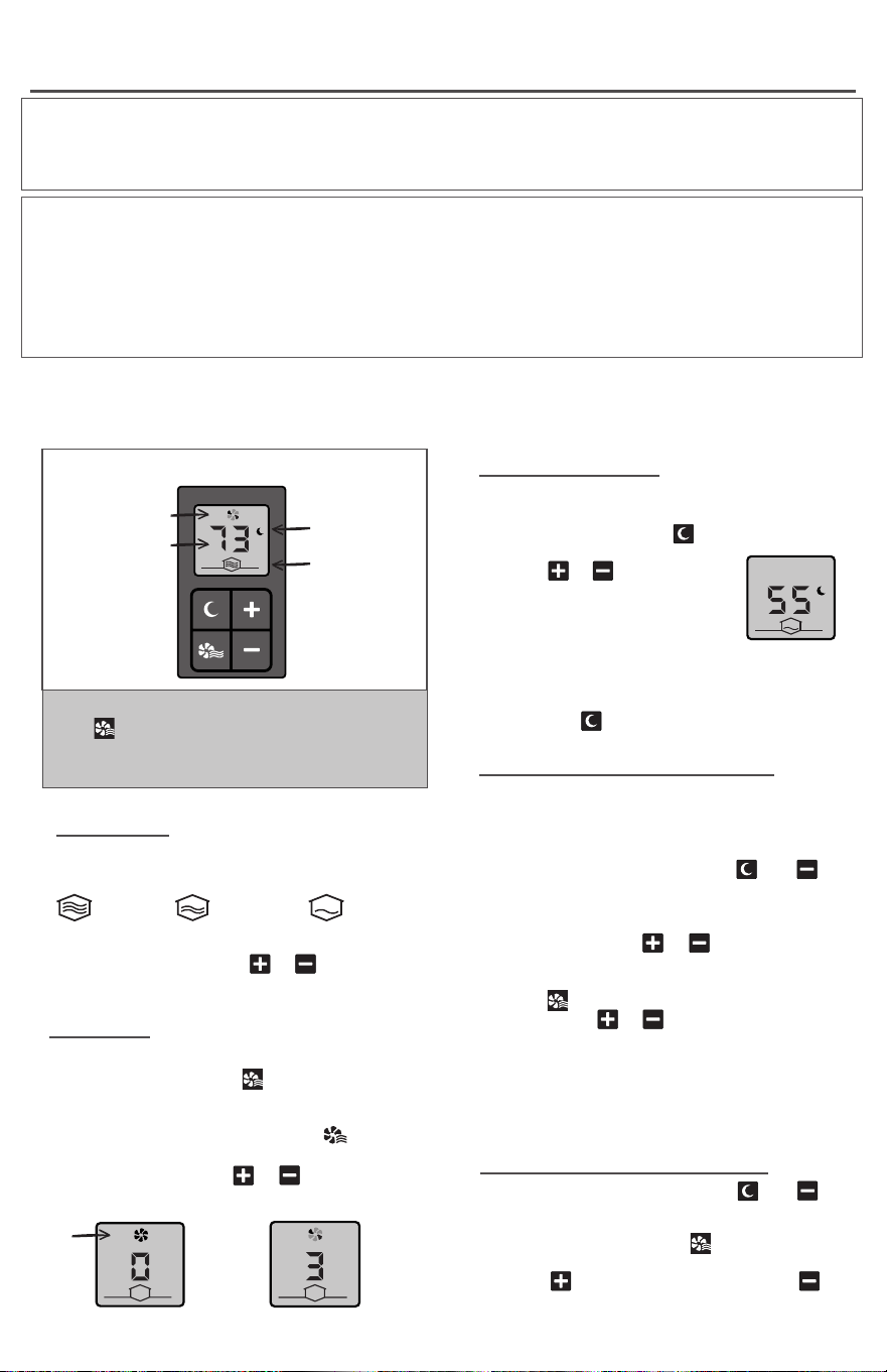
Digital Display and Control Buttons
NIGHT/AWAY MODE
Program a lower temperature for energy
savings at night, or if you’re not in the room.
• In HEAT mode, press . Display shows
MAX/MIN TEMPERATURE LOCK
Program maximum and/or minimum tempera-
ture settings as a child safety or tamper-proof
option.
MAXIMUM 86
˚
F (30
˚
C):
• In FAN mode, press and hold and at
the same time, until display shows
temperature.
• Release buttons. While temperature alter-
nates with HL, use or to set maximum
temperature.
MINIMUM 40
˚
F (4.4
˚
C):
• Press . While temperature alternates
with LL, use or to set minimum
temperature.
Wait 10 to 15 seconds and display returns to
0. Your settings are saved.
To change the lock temperatures, follow the
same instructions.
START HEATING/SET TEMPERATURE
• In HEAT mode, press or to adjust
temperature.
FAN MODE
Stops heating, or circulates air without heat.
• In HEAT mode, press . Fan runs at a
low level until heater cools down. This
lasts for 5 to 10 minutes.
When fan stops completely, NO shows
in display.
• In FAN mode, press or to adjust fan
speed.
CHANGE DISPLAY TO CELSIUS
• In FAN mode, press and hold and at
the same time, until display shows
temperature.
• Release buttons. Press twice. Display
alternates between
o
F and U
.
• Press to convert to Celsius. Press to
convert back to Fahrenheit.
• Wait 10 to15 seconds and display returns to
0. Your settings are saved.
HEAT MODE
Digital display shows room temperature, and
the level of heat being output.
Full
Power
Medium
Power
Low
Power
Fan Only /
High Speed
Night / Away
Mode
Night/Away
Mode
Heat
Output
Temperature
Fan
Operation
Up
Down
Night/Away
Heat/Fan
Mode
Stop Heating /
No Fan
u
SWITCHING MODES
Use button to change between modes.
In HEAT mode, display shows temperature.
In FAN mode, display shows 0, 1, 2 or 3.
Your Intelligent fan-forced heater has a variable speed blower that auto adjusts heat output based
on the temperature setting. The heater varies wattage output for maximum eciency. Temperature
Range: 40
˚
F to 86
˚
F (4.4
˚
C to 30
˚
C). The room temperature is controlled by the built-in digital thermo-
stat. A wall thermostat cannot be used with this heater.
NO
NO
moon icon.
• Press or to adjust
temperature. The default
low temperature is 55
˚
F
(12.8
˚
C).
• Fan runs at a low level until
heater cools down. This
lasts for 5 to 10 minutes.
To exit NIGHT/AWAY mode when you wake or
return, press .
Complete installation
After installation, turn your heater to the highest setting and let it run for 30 minutes. Some smoking may
occur as the element initially burns o residue from manufacturing.
If your heater shows signs of overheating, such as glowing red or repeatedly getting unusually hot and
shutting o, immediately turn o the circuit breaker and review the “KNOW YOUR VOLTAGE” section or
call us.
If the high-temperature safety shuto trips more than once a day, replace the heater.
OPERATING INSTRUCTIONS
8
Clean heater at least every 6 months or as required. Do not lubricate motor.
1. Turn o power at the main disconnect panel.
2. Wait for the heater to cool.
3. Remove grill.
4. Wash grill with hot soapy water and dry.
5. Blow air through the heating element with a hair
dryer or shop vacuum on blow cycle.
6. Clean the fan with a vacuum cleaner.
7. Replace grill.
8. Turn power back on at the main disconnect
panel.
Any service other than cleaning should be performed by an authorized service
representative.
High-temperature safety shuto
All Intelligent Fan-forced heaters come with a built-in high-temperature safety shuto that stops electricity
flowing to the heater if it gets too hot inside. See TROUBLESHOOTING below if you’re experiencing
problems with your heater.
Symptom Problem Solution
TROUBLESHOOTING
Heater
smells after
installation or
not being used.
1. Odor from element
manufacturing process.
2. Dust or lint inside the heater.
3. Supply connections are loose.
1. In a new installation, some smoking may occur as
the element initially burns o residue from manufactur-
ing. It typically goes away within several hours.
2. Clean heater (see “MAINTAINING YOUR HEATER”
above for instructions).
3. Turn o power at main disconnect panel. Inspect
and/or tighten all the wire connectors inside the heater
and at any connection points.
Heater doesn’t
work at all.
1. Supply connections are loose.
2. Heater has tripped its built-in
high-temperature safety shuto
and electricity has stopped
flowing to the heater.
3. Circuit breaker is faulty.
4. Heater is in FAN mode at 0
setting.
5. Defective digital thermostat.
1. Turn o power at main disconnect panel. Inspect
and/or tighten all the wire connectors inside the heater
and at any connection points.
2. TO RESET: Turn power o at main disconnect
panel. Allow 10 minutes to cool. Make sure heater is
not blocked and is clean. Push reset button. Restore
power. If the high-temperature safety shuto trips more
than once a day, replace the heater.
3. Call a licensed electrician.
4. Press mode button to switch to HEAT mode (display
shows room temperature).
5. Replace the heater.
Breaker trips
immediately
after installing
heater.
1. A short circuit exists in the
electrical supply wires or heater
wiring.
2. Circuit is overloaded.
3. Circuit breaker is faulty.
1. An incorrect connection in the heater or electrical
supply wires may cause sparking or arcing. Inspect
all heater and electrical supply wiring insulation for
damage or call an electrician.
2. Use a lower wattage heater, or reduce the number
of heaters on the circuit.
3. Call a licensed electrician.
Heater blows
cold air or
doesn’t get hot.
1. Element has failed.
2. Heater is in FAN mode at 0
setting.
3. Make sure temperature lock
has not been set. Thermostat
setpoint range is 40
˚
F to 86
˚
F
(4.4
˚
C to 30
˚
C).
1. Replace heater.
2. Press mode button to switch to HEAT mode (display
shows room temperature).
3. See MAX/MIN TEMPERATURE LOCK on page 7.
Fan/motor
doesn’t spin.
1. Defective motor or motor out
of alignment.
1. Replace motor.
Heater doesn’t
turn o.
1. Heater continues to run but
only at a low speed.
2. Incorrect heater wattage for
room size.
1. If desired room temperature is being maintained, a
slower fan, and lower heat output are normal for this
heater in its energy saving mode.
2. Install additional heaters if circuit allows.
Built-in high-
temperature
safety shuto
keeps tripping.
1. Airflow is blocked. 1. Remove obstruction(s). Maintain minimum distances
(See Page 2).
Reduce-Reuse-Recycle
This product is made primarily of recyclable materials. You can reduce your carbon footprint by recycling this
product at the end of its useful life. Contact your local recycling support center for further recycling instructions.
Rev 03/05/21 #720065
If you are uncomfortable working with electricity, running electrical supply
wire or installing a circuit breaker, please consult a licensed electrician.
©2021 Glen Dimplex Americas Printed in USA
MAINTAINING YOUR HEATER