Loading ...
Loading ...
Loading ...
BLADE WIDTH
• Width of blade describes distance from tip of a tooth
to back of blade.
• Width of blade affects rigidity of blade. A wider blade
wanders less and produces a straighter cut.
• Width of blade also limits the smallest radius which can
be cut. A IA" wide blade can cut about a ½" radius.
BLADE THICKNESS
• Blade thickness describes the distance between
sides of blade. A thicker blade has more rigidity and
stronger teeth.
• A narrow thick blade is used to cut curves while a
wide thin blade is used to make long, straight cuts.
BLADE PITCH
• Pitch describes number of teeth per inch or tooth
size. A blade with more teeth per inch produces a
smoother cut.
• The type of material being cut determines number of
teeth which should be in contact with work.
• For soft materials, the proper blade has between 6
to 8 teeth per inch.
• When cutting hard materials, where shocking is
more detrimental, use a blade with 8 to 12 teeth per
inch.
• There should always be at least three teeth in
contact with cut to avoid shocking blade.
• Blade shocking occurs when pitch is too large and
blade tooth encounters too much material. This can
strip teeth from blade.
• Blade manufacturers are prepared to supply
information about blades for specific applications.
TYPE OF CUT
• Contour cutting is done by guiding workpiece
free-handed to produce curved shapes.
• Beveled cutting is done by tilting saw head and using
proper work guide method.
• Regardless of which work guiding method is used, a
workpiece which overhangs table by more than 5"
needs proper support.
CONTOUR SAWING
• When contour sawing, use both hands to keep work-
piece flat against table and guided along desired
path.
• Avoid positioning hands in line with blade. If hands
slip, they could contact blade.
• Try to stand to front of the saw and use hands over
the portion of table which is to right of blade and
before cut.
• Cut small corners by sawing around them. Saw to
remove scrap until desired shape is obtained.
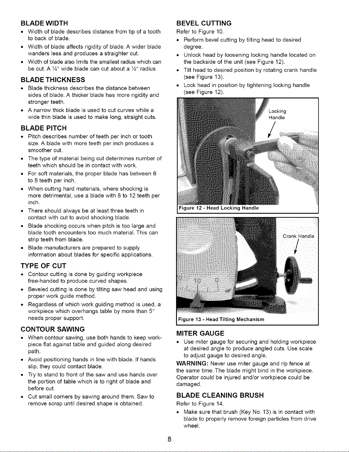
BEVEL CUTTING
Refer to Figure 10.
• Perform bevel cutting by tilting head to desired
degree.
• Unlock head by loosening locking handle located on
the backside of the unit (see Figure 12).
• Tilt head to desired position by rotating crank handle
(see Figure 13).
• Lock head in position by tightening locking handle
(see Figure 12).
Figure 12 - Head Locking Handle
Figure 13 -Head Tilting Mechanism
MITER GAUGE
• Use miter gauge for securing and holding workpiece
at desired angle to produce angled cuts. Use scale
to adjust gauge to desired angle.
WARNING: Never use miter gauge and rip fence at
the same time. The blade might bind in the workpiece.
Operator could be injured and/or workpiece could be
damaged.
BLADE CLEANING BRUSH
Refer to Figure 14.
• Make sure that brush (Key No. 13) is in contact with
blade to properly remove foreign particles from drive
wheel.
8
Loading ...
Loading ...
Loading ...