Loading ...
Loading ...
Loading ...
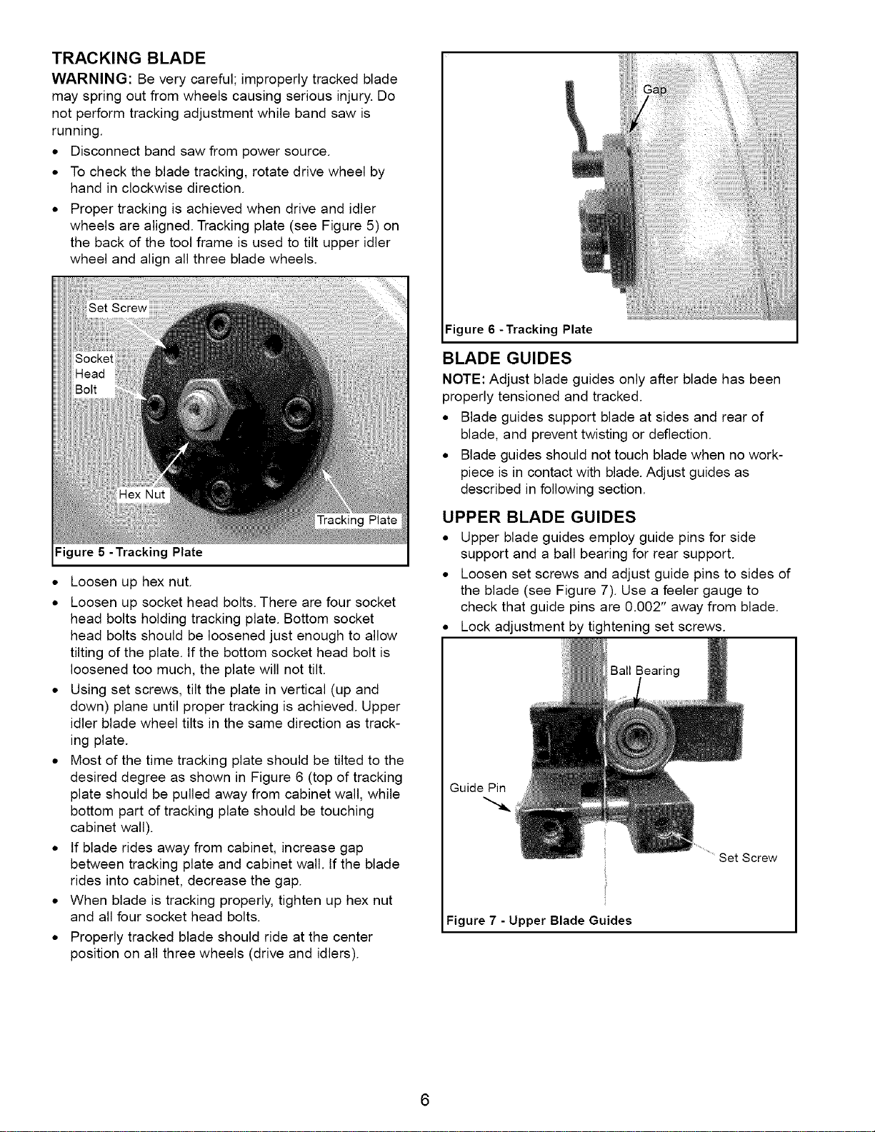
TRACKING BLADE
WARNING: Be very careful; improperly tracked blade
may spring out from wheels causing serious injury. Do
not perform tracking adjustment while band saw is
running.
• Disconnect band saw from power source.
• To check the blade tracking, rotate drive wheel by
hand in clockwise direction.
• Proper tracking is achieved when drive and idler
wheels are aligned. Tracking plate (see Figure 5) on
the back of the tool frame is used to tilt upper idler
wheel and align all three blade wheels.
Hex Nut
Figure 5 -Tracking Plate
• Loosen up hex nut.
• Loosen up socket head bolts. There are four socket
head bolts holding tracking plate. Bottom socket
head bolts should be loosened just enough to allow
tilting of the plate. If the bottom socket head bolt is
loosened too much, the plate will not tilt.
• Using set screws, tilt the plate in vertical (up and
down) plane until proper tracking is achieved. Upper
idler blade wheel tilts in the same direction as track-
ing plate.
• Most of the time tracking plate should be tilted to the
desired degree as shown in Figure 6 (top of tracking
plate should be pulled away from cabinet wall, while
bottom part of tracking plate should be touching
cabinet wall).
• If blade rides away from cabinet, increase gap
between tracking plate and cabinet wall. If the blade
rides into cabinet, decrease the gap.
• When blade is tracking properly, tighten up hex nut
and all four socket head bolts.
• Properly tracked blade should ride at the center
position on all three wheels (drive and idlers).
:igure 6 -Tracking Plate
BLADE GUIDES
NOTE: Adjust blade guides only after blade has been
properly tensioned and tracked.
• Blade guides support blade at sides and rear of
blade, and prevent twisting or deflection.
• Blade guides should not touch blade when no work-
piece is in contact with blade. Adjust guides as
described in following section.
UPPER BLADE GUIDES
• Upper blade guides employ guide pins for side
support and a ball bearing for rear support.
• Loosen set screws and adjust guide pins to sides of
the blade (see Figure 7). Use a feeler gauge to
check that guide pins are 0.002" away from blade.
• Lock adjustment by tightening set screws.
Ball Bearing
Guide Pin
Set Screw
Figure 7 - Upper Blade Guides
6
Loading ...
Loading ...
Loading ...