Loading ...
Loading ...
Loading ...
FINAL INSTALLATION
14
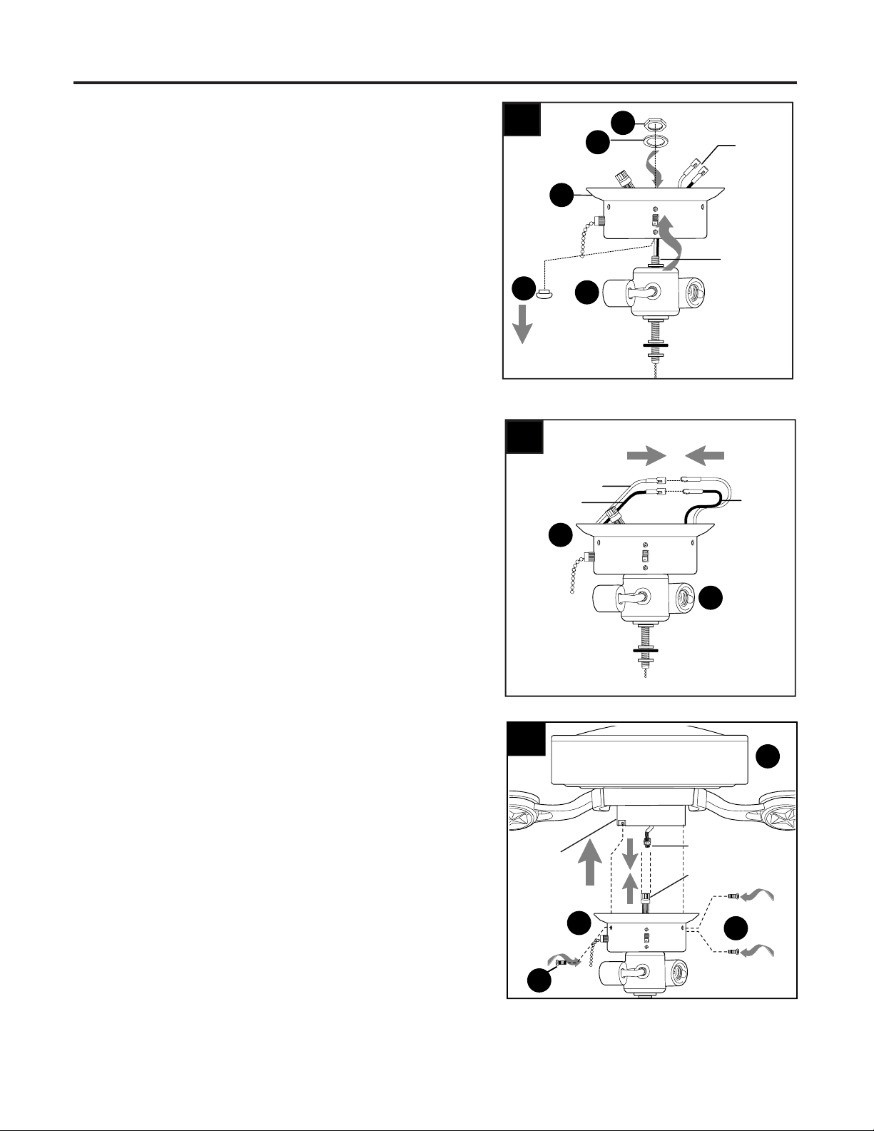
4.
6.
Remove three switch housing screws (R) from motor
plate on underside of the motor housing (E). Connect
male plug from motor housing (E) to female plug from
switch housing (N), matching up the colors on the
plugs for correct fit. Make sure plugs connect tightly.
Carefully arrange wires inside switch housing (N).
Align holes in switch housing (N) with holes in motor
plate, and secure switch housing (N) with three switch
housing screws (R) previously removed. Tighten all
screws securely.
Note: Make sure to align gap on motor plate with the
reverse switch on switch housing (N) for a correct fit.
To install the fan with the light kit, remove
preassembled hex nut (U) and lock washer (V) from
threaded rod at top of light kit fitter (H). Punch center
cap (S) out of switch housing (N) with a screwdriver
(not included). Gently feed molex wires (one at a
time) from light kit fitter (H) through hole in middle of
switch housing (N), and then screw switch housing
(N) onto threaded rod on light kit fitter (H). Tighten
hex nut (U) over lock washer (V) for a secure fit.
Connect WHITE molex wire from light kit fitter
(H) to WHITE molex wire from switch housing
(N). Connect BLACK molex wire from light kit
fitter (H) to BLUE molex wire from switch
housing (N). Make sure molex wire connections
snap together securely.
5.
4
5
Molex
Wires
Blue
White
Molex
Wires
S
U
V
Threaded
Rod
Molex
Wires
H
H
N
N
6
E
N
R
R
Motor
Plate
Male Plug
Female
Plug
Black
Loading ...
Loading ...
Loading ...