Loading ...
Loading ...
Loading ...
www.usaprocom.com
200068-01A16
INSTALLATION
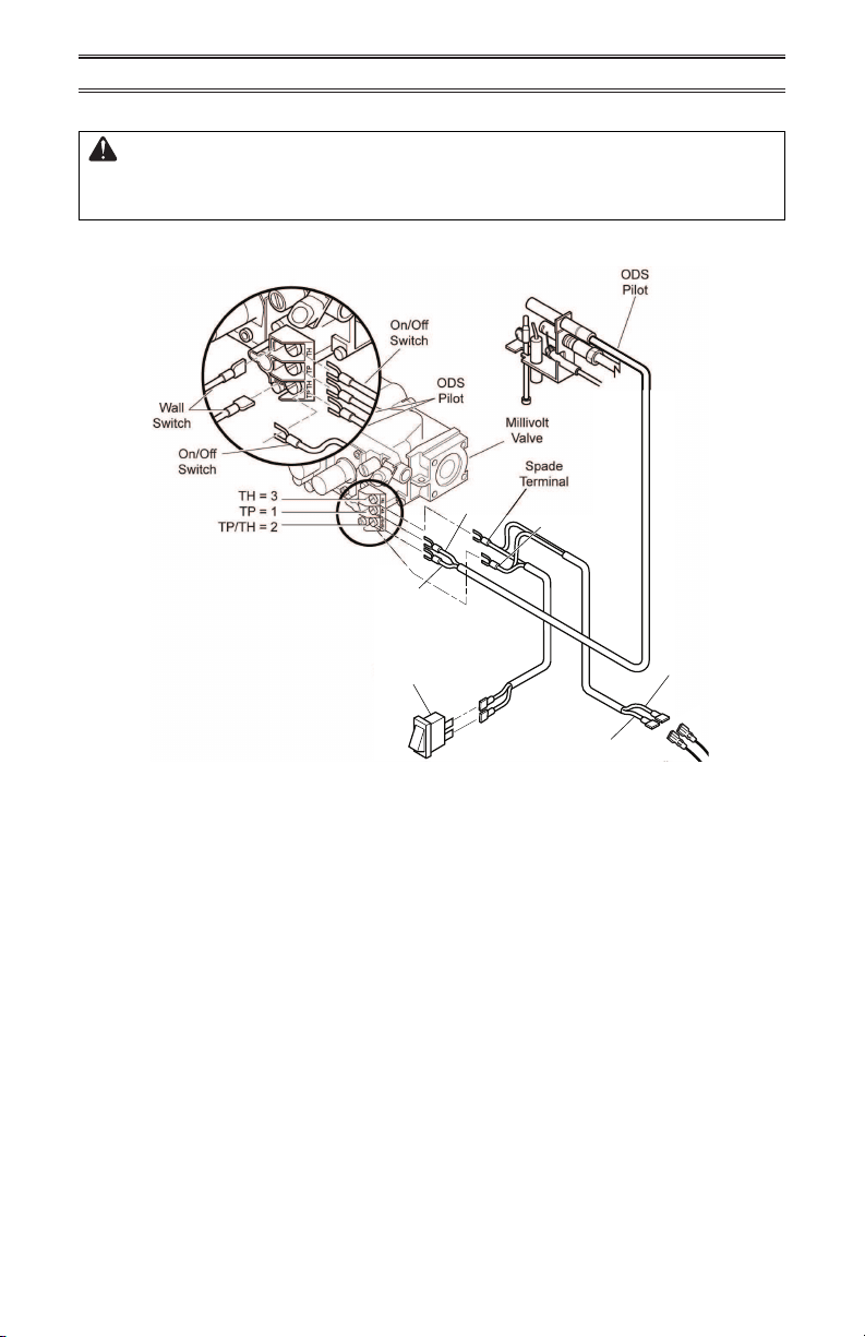
Figure 18 - Wiring Diagram
ELECTRICAL WIRING (MILLIVOLT)
CAUTION: Label all wires prior to disconnection when servicing
controls. Wiring errors can cause improper and dangerous opera-
tion. Verify proper operation after servicing.
Note: The millivolt valve is a self-powered combination gas control that does not require
110 VAC to operate.
CONNECTING REMOTE RECEIVER
MODELS WZ(N,L)(18,24,30)MVA ONLY
Models WZ(N,L)(18,24,30)MVA can be connected to an aftermarket hand held remote receiver
(not supplied by ProCom Heating, Inc.)
Refer to the remote receiver manufacturer's installation Instructions and the Wiring Diagram
shown in Figure 18 for proper connection and use.
OPTIONAL POSITIONING OF THERMOSTAT SENSING BULB
For masonry and factory-built metal replace
Optional Wall Switch
or Remote Receiver
If your log set cycles to pilot, but the room
temperature drops to a lower than ideal
comfort level before the log set comes back
on, you may want to reposition the thermostat
sensing bulb.
The thermostat sensing bulb is located near
the gas valve assembly on the mounting
bracket. This location allows the thermostat
to keep the room temperature at an ideal
comfort level for most replace applications.
For positioning the thermostat sensing bulb
elsewhere, a mounting clip is available.
Tools needed: 1/4" hex driver or socket.
1. Remove logs. Locate the gas valve as-
sembly and thermostat sensing bulb.
Red
Red
White
Switch
Black
Green
Loading ...
Loading ...
Loading ...