Loading ...
Loading ...
Loading ...
1111
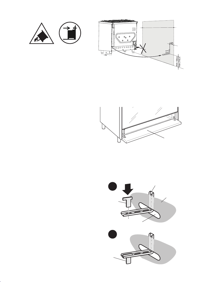
ANTI-TILT BRACKET
Important!
To restrain the appliance and prevent it
tipping accidentally, t a bracket to its
rear to x it securely to the wall. Make
sure you also t the supplied lock pin to
the anti-tilt bracket.
If installing the cooker above a plinth
(without tting the adjustable feet),
revise the installation dimensions
accordingly considering that the feet
have the following measures: min 85
mm - max 135 mm.
To t the anti-tilt bracket:
1. After you have located where the
cooker is to be positioned, mark on the
wall the place where the two screws
of the anti-tilt bracket have to be tted.
Please follow the indications given in
g. 7.
2. Drill two 8 mm diameter holes in
the wall and insert the plastic plugs
supplied.
Important!
Before drilling the holes, check that
you will not damage any pipes or
electrical wires.
3. Loosely attach the anti-tilt bracket with
the two screws supplied.
4. Move the cooker to the wall and adjust
the height of the anti-tilt bracket so
that it can engage in the slot on the
cooker’s back, as shown in g. 7.
5. Tighten the screws attaching the anti-
tilt bracket.
6. Push the cooker against the wall so
that the anti-tilt bracket is fully inserted
in the slot on the cooker’s back.
7. Access the bracket and t the lock pin:
■ Open the pivoting panel (g. 8).
■ Fit the lock pin through the
bracket, as shown (g. 9).
■ Close the pivoting panel.
Pivoting
panel
Lock pin
correctly
fitted
Lock pin
Slot on the
cooker’s back
Cooker’s
back
Anti-tilt bracket
attached on the
rear wall
1
2
Figure 7
Figure 8
Figure 9
900 mm
Loading ...
Loading ...
Loading ...