
Operator's Manual
CRAFTSMAN°
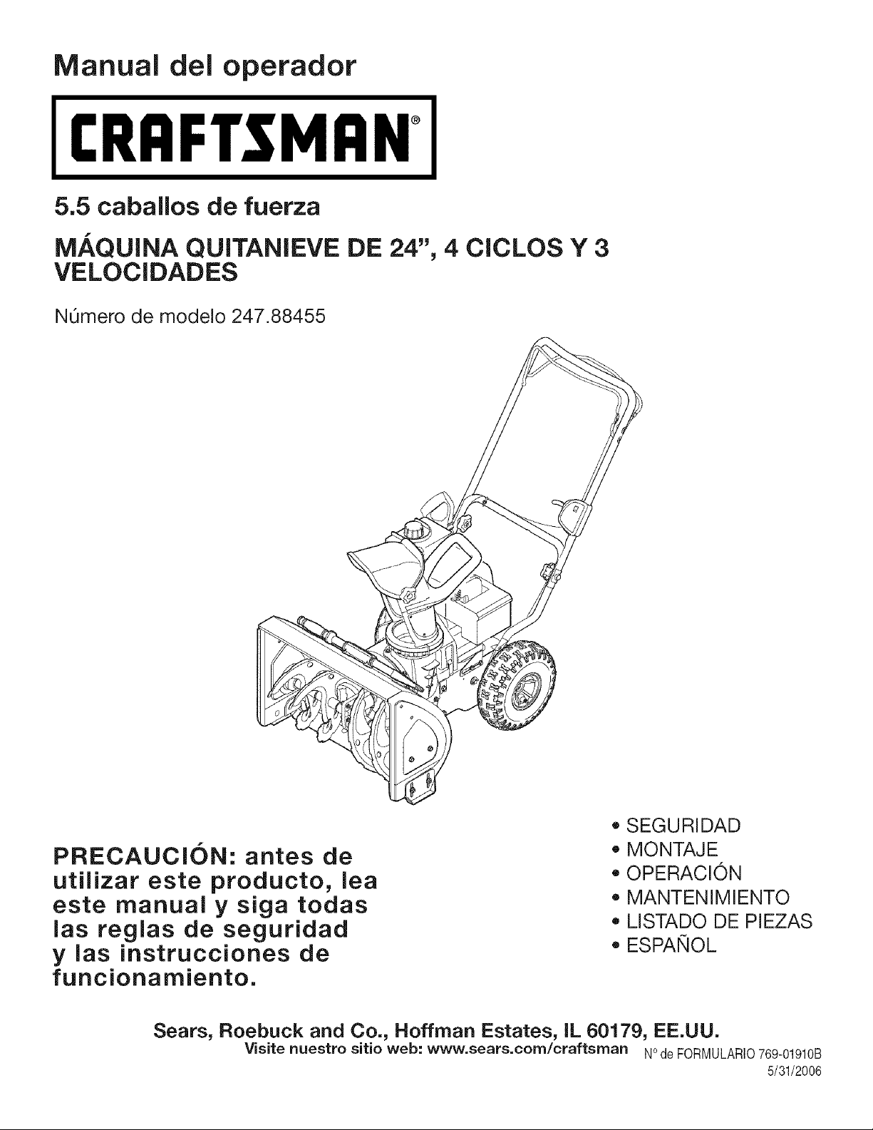
5.5 Horse Power
24-iNCH 4-CYCLE 3-SPEED SNOW THROWER
Model No. 247.88455
CAUTION: Before using
this product, read this
manual and follow all
safety rules and operating
instructions.
• SAFETY
• ASSEMBLY
OPERATION
MAINTENANCE
PARTS LIST
ESPANOL R 27
Sears, Roebuck and Co., Hoffman Estates, IL 60179, U.S.A.
Visit our website: www, sears,corn/craftsrnan FORMNO.769-01910B
5/30/2006
Warranty Statement ................................................. Page 2 Maintenance and Service ................................. Pages 12-15
Safety Labels ........................................................... Page 3 Off Season Storage & Troubleshooting ............. Page 16-17
Rules of Safe Operation ..................................... Pages 4-5 Parts List .......................................................... Pages 18-25
Set Up & Adjustment .......................................... Pages 6-7 Espa_ol ................................................................... Page 27
Know Your Snow Thrower .................................. Pages 8-9 Service Numbers ............................................... Back Cover
Operation ........................................................ Pages 10-11
Two-YearWarranty on Craftsman Snow Thrower
Fortwoyearsfromthedate of purchase,whenthis CraftsmanSnowThroweris maintained,lubricatedandtunedupaccordingto the instructions
inthe owner'smanual,Searswill repair,free of charge,anydefectin materialandworkmanship.IfthisCraftsmansnowthroweris used for
commercialor rentalpurposes,this warrantyappliesfor only 30 days from thedateof purchase.
Thiswarrantydoesnot cover:
• Expendableitemswhichbecomewornduringnormaluse,suchas skidshoes,shaveplateandsparkplugs.
Repairsnecessarybecauseof operatorabuseor negligence,includingbentcrankshaftsand the failureto maintainthe equipmentaccording
to the instructionscontainedinthe owner'smanual.
WARRANTYSERVICEIS AVAILABLEBYRETURNINGTHECRAFTSMANSNOWTHROWERTOTHE NEAREST
SEARSPARTS& REPAIRCENTERINTHEUNITEDSTATES.
This warrantyappliesonly whilethis productis in use inthe UnitedStates.
TO LOCATETHENEARESTSEARSPARTS& REPAIRCENTERORTO SCHEDULESERVICE,
SIMPLYCONTACTSEARSAT1-800-4-MY-HOME®.
Thiswarrantygivesyou specificlegalrightsandyou mayalso haveotherrightswhichmayvaryfromstate to state.
SEARS,ROEBUCKANDCO., D/817WA,HOFFMANESTATES,IL 60179
Repair Protection Agreements
Congratulationson makinga smart purchase.YournewCraftsman®
productis designedand manufacturedfor yearsof dependableopera-
tion.But likeallproducts,it mayrequirerepairfromtimeto time.That's
whenhavinga RepairProtectionAgreementcansaveyoumoneyand
aggravation.
Here'swhat'sincludedin the Agreement:
Expertserviceby our 12,000professionalrepairspecialists
Unlimitedserviceand no chargefor partsand laboronall covered
repairs
Productreplacementif yourcoveredproductcan'tbe fixed
Discountof 10%from regularpriceof serviceand service-related
partsnotcoveredby theagreement;also,10%off regularprice of
preventivemaintenancecheck
Fasthelpby phone- phonesupportfroma Searstechnicianon
productsrequiringin-homerepair,plus convenientrepair
scheduling
Purchasea RepairProtectionAgreementnowandprotectyourself
fromunexpectedhassleandexpense.
Once youpurchasethe Agreement,a simplephonecall is all that it
takesfor youto scheduleservice.Youcan call anytimeday or night, or
schedulea serviceappointmentonline.
Searshasover12,000professionalrepairspecialists,who have
accessto over4.5millionqualitypartsandaccessories.That'sthe
kindof
professionalismyou cancountonto helpprolongthe life of yournew
purchaseforyears to come.PurchaseyourRepairProtectionAgree-
menttoday!
Some limitationsand exclusionsapply. For pricesand additional
informationcall 1-800-827-6655.
Sears Installation Service
ForSearsprofessionalinstallationof homeappliances,garagedoor
openers,waterheaters,andother majorhomeitems,in the U.S.A.call
1-800-4-MY-HOME®
Horse Power:
Engine Oil:
Fuel:
Spark Plug:
Engine:
5.5
SAE 5W-30
Unleaded Gasoline
Champion@ RJ19LM
Tecumseh LH195SP
Model Number .............................................................
Serial Number ..............................................................
Date of Purchase ..........................................................
Record the model number, serial number
and date of purchase above
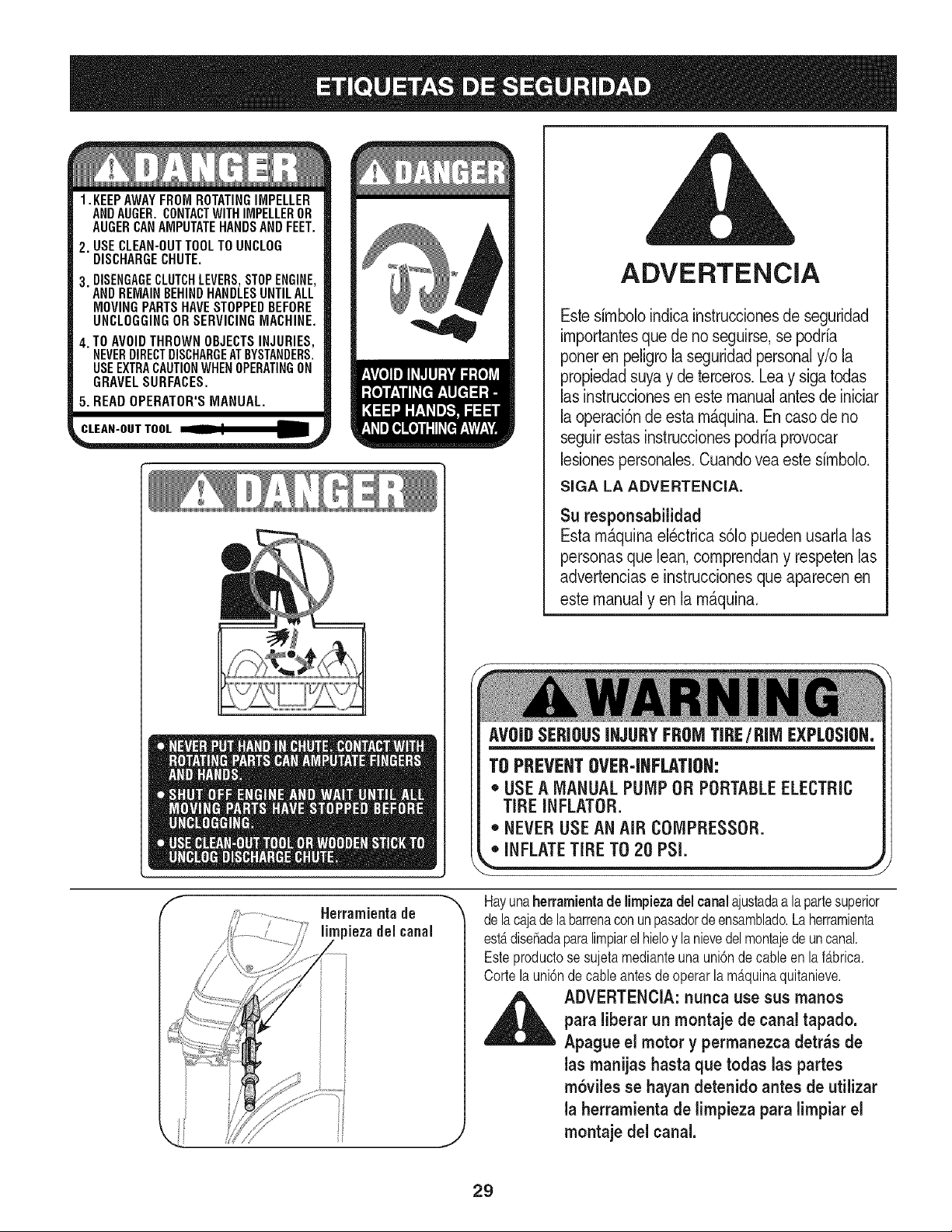
1.KEEPAWAYFROMROTATINGIMPELLER
ANDAUGER.CONTACTWITHIMPELLEROR
AUGERCANAMPUTATEHANDSANDFEET.
2. USECLEAN-OUTTOOLTOUNCLOG
DISCHARGECHUTE.
3. DISENGAGECLUTCHLEVERS,STOPENGINE,
ANDREMAINBEHINDHANDLESUNTILALL
MOVINGPARTSHAVESTOPPEDBEFORE
UNCLOGGINGORSERVICINGMACHINE.
4. TO AVOIDTHROWNOBJECTSINJURIES,
NEVERDIRECTDISCHARGEATBYSTANDERS.
USEEXTRACAUTIONWHENOPERATINGON
GRAVELSURFACES.
5. READOPERATOR'SMANUAL.
CLEAN-OUTTOOL
WARNING
This symbol pointsout importantsafety instruc-
tions which, if notfollowed,could endangerthe
personalsafety and/or propertyd yourselfand
others. Readand followall instructionsinthis
manual beforeattemptingto operatethis machine.
Failureto complywith these instructionsmay
resultin personalinjury.When you see this symbol
HEED iTS WARNING!
Your Responsibility
Restrictthe use of this power machine to persons
who read, understandand follow the warnings
and instructions in this manualand on the ma-
chine.
AVOIDSERIOUSINJURYFROMTIRE/RIM EXPLOSION.
TO PREVENTOVER-INFLATION:
* USE A MANUAL PUMP OR PORTABLEELECTRIC
TIRE INFLATOR.
* NEVER USEAN AiR COMPRESSOR.
,,"iNFLATETiRE702OPSi, j
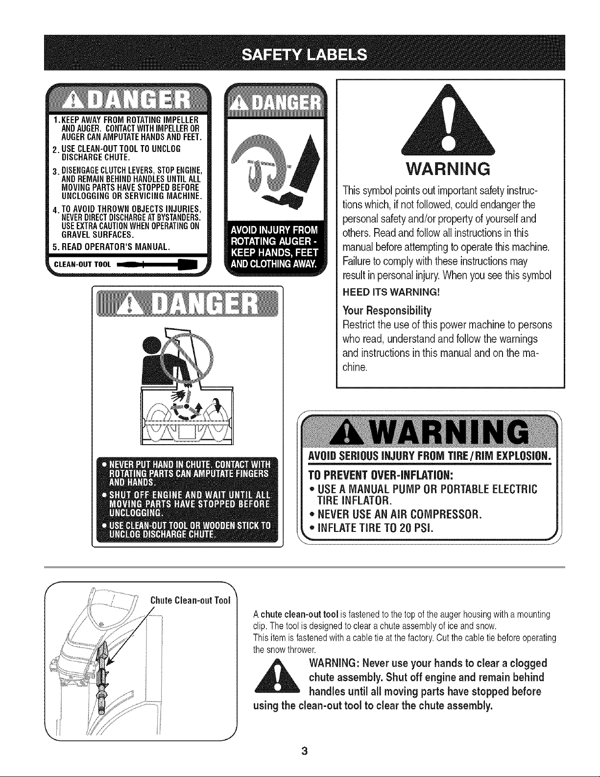
ChuteClean-outTool
A chute clean-out tool is fastenedto the top of the augerhousingwith a mounting
clip.Thetool is designedto clear achuteassemblyof iceand snow.
Thisitemis fastenedwitha cabletie at the factory.Cut the cabletie beforeoperating
the snowthrower.
WARNING: Never use your hands to clear a clogged
chute assembly. Shut off engine and remain behind
handles until all moving parts have stopped before
using the clean-out tool to clear the chute assembly.
WARNING: Engine Exhaust, some of its constituents,and certain vehicle components contain or emit
chemicals known to State of California to cause cancer and birth defects or other reproductiveharm.
DANGER: This machine was built to be operated according to the rules for safe operation in this manual. As with any type
of power equipment, carelessness or error on the part of the operator can result in serious injury. This machine is capable
of amputating hands and feet and throwing objects. Failureto observe the following safety instructionscould result in
serious injury or death.
WARNING: This symbol pointsout important safetyinstructionswhich, if not followed,couldendangerthe
personalsafety and/or property of yourselfand others. Readand follow all instructionsin this manual before
attemptingto operatethis machine. Failureto complywith these instructionsmay resultin personalinjury.
When you see this symbol.HEED ITS WARNING!
Your Responsibility: Restrict the use of this power machine to persons who read, understandand follow the warnings
and instructions in this manual and on the machine.
Preparation
1. Thoroughlyinspectthe areawherethe equipmentisto be used. Remove
all doormats,newspapers,sleds, boards,wiresand otherforeignobjects,
whichcould be trippedoveror thrownbythe auger/impeller.
2. Alwayswearsafetyglassesor eye shields during operationandwhile
performingan adjustmentor repairto protectyoureyes.Thrownobjects
which ricochetcan causeserious injuryto the eyes.
3. Donotoperate withoutwearingadequatewinteroutergarments.Donot
wearjewelry, longscarvesor otherloose clothing,whichcouldbecome
entangledinmoving parts.Wearfootwearwhichwill improvefooting on
slippery surfaces.
4. Usea groundedthree-wireextensioncord and receptaclefor all unitswith
electricstart engines.
5. Adjustcollector housingheightto clear gravelor crushedrocksurfaces.
6. Disengageall control leversbeforestartingthe engine.
7. Neverattemptto make anyadjustmentswhileengine is running,except
where specificallyrecommendedinthe operator'smanual.
8. Letengineand machineadjustto outdoortemperaturebefore startingto
clear snow.
9. To avoidpersonalinjury or propertydamageuseextremecare in handling
gasoline. Gasolineis extremelyflammableandthe vaporsareexplosive.
Seriouspersonalinjury can occurwhen gasolineis spilled on yourself
or yourclothes,which can ignite.Washyourskin andchangeclothes
immediately.
a. Useonlyan approvedgasolinecontainer.
b. Extinguishall cigarettes,cigars,pipesand othersourcesof ignition.
c. Neverfuel machineindoors.
d. Neverremovegas cap or addfuel whilethe engineis hot or running.
e. Allowengineto cool at least two minutesbefore refueling.
f. Neveroverfill fuel tank. Fill tankto no morethan _/zinch belowbottom
of filler neckto providespacefor fuel expansion.
g. Replacegasolinecap andtighten securely.
h. If gasolineis spilled, wipeit off the engine andequipment.Move
machineto anotherarea. Wait5 minutesbeforestartingthe engine.
i. Neverstore the machineor fuel container insidewherethere is an open
flame, sparkor pilot light (e.g.furnace,water heater,space heater,
clothesdryeretc.).
j. Allow machineto cool at least 5 minutesbeforestoring.
Training
1. Read,understand,andfollowallinstructionsontile machineand inthe
manual(s)beforeattemptingto assembleandoperate.Keepthis manualin
a safeplaceforfuture andregularreferenceandfor orderingreplacement
parts.
2. Be familiarwith allcontrolsandtheir properoperation.Knowhowto stop
themachineand disengagethem quickly.
3. Neverallowchildrenunder14 yearsoldto operatethis machine.Children
14 yearsold andovershouldreadandunderstandthe operationinstruc-
tionsand safetyrulesin this manualandshouldbe trainedandsupervised
bya parent.
4. Neverallowadultsto operatethis machinewithoutproperinstruction.
5. Thrownobjectscan causeserious personalinjury.Planyoursnow-throwing
patternto avoiddischargeof materialtowardroads,bystandersandthelike.
6. Keepbystanders,helpers,pets andchildrenat least 75 feetfromthe
machinewhileit is in operation.Stopmachineif anyoneentersthe area.
7. Exercisecautionto avoidslippingor falling,especiallywhen operatingin
reverse.
4
Operation
1. Do notputhands orfeet near rotatingparts,intile auger/impellerhousing
orchute assembly.Contactwith the rotating partscan amputatehands
andfeet.
2. The auger/impellercontrol leveris a safetydevice.Neverbypassits
operation.Doingso makesthemachineunsafeand maycause personal
injury.
3. The controlleversmust operateeasily inboth directionsand automatically
returnto the disengagedpositionwhenreleased.
4. Neveroperatewitha missingor damagedchute assembly.Keepall safety
devicesin placeand working.
5. Neverrunan engine indoorsor in a poorlyventilatedarea. Engineexhaust
containscarbonmonoxide,anodorlessanddeadlygas.
6. Do notoperatemachinewhileunderthe influenceof alcoholor drugs.
7. Mufflerand enginebecomehotand can causea burn. Do nottouch.
8. Exerciseextremecautionwhenoperatingon orcrossinggravel surfaces.
Stay alert forhidden hazardsor traffic.
9. Exercisecautionwhen changingdirectionandwhile operatingon slopes.
10.Planyoursnow-throwingpatternto avoiddischargetowards windows,
walls, carsetc.Thus, avoidingpossiblepropertydamageor personal
injurycausedby a ricochet.
11.Neverdirectdischargeat children,bystandersand pets or allowanyonein
front of the machine.
12.Do not overloadmachinecapacityby attemptingto clearsnow at toofast
of a rate.
13.Neveroperatethis machinewithoutgood visibilityor light. Alwaysbe sure
of yourfootingand keepa firm holdon the handles.Walk, never run.
14.Disengagepowerto the auger/impellerwhentransportingor notin use.
15.Neveroperatemachineat hightransport speedson slipperysurfaces.
Lookdown and behindand use carewhenbackingup.
16.If the machineshouldstart to vibrateabnormally,stop the engine,
disconnectthespark plug wire andground it againsttheengine.Inspect
thoroughlyfor damage.Repairanydamagebeforestartingand operating.
17.Disengageall control leversandstop enginebeforeyou leavethe operat-
ing position(behindthe handles).Waituntil the auger/impellercomes
to a completestopbeforeuncloggingthechute assembly,makingany
adjustments,or inspections.
18.Neverputyour hand inthe dischargeor collectoropenings.Alwaysuse
theclean-outtool providedto unclogthe dischargeopening.Do notunclog
chuteassemblywhileengineis running.Shutoff engineand remain
behind handlesuntil allmoving partshavestoppedbeforeunclogging.
19.Useonly attachmentsand accessoriesapprovedbythe manufacturer(e.g.
wheelweights,tirechains,cabsetc.).
20.If situationsoccurwhich are not coveredin this manual,use careand
goodjudgment. ContactyourSears ServiceCenterfor assistance.
Maintenance & Storage
1. Nevertamperwith safetydevices.Checktheir properoperationregularly.
Referto the maintenanceand adjustmentsectionsof this manual.
2. Beforecleaning,repairing,or inspectingmachinedisengageallcontrol
leversand stoptheengine. Wait until theauger/impellercometo a
completestop.Disconnectthe spark plugwire and groundagainstthe
engine to preventunintendedstarting.
3. Check bolts andscrewsfor propertightnessat frequentintervalsto keep
the machinein safeworkingcondition.Also, visuallyinspectmachinefor
any damage.
4. Donotchangetheenginegovernorsettingor over-speedtheengine.The
governorcontrolsthe maximumsafe operatingspeedof the engine.
5. Snow throwershaveplatesandskid shoesaresubjectto wear and
damage.Foryour safetyprotection,frequentlycheck all componentsand
replacewithoriginal equipmentmanufacturer's(OEM)parts only."Useof
parts which do notmeet the originalequipmentspecificationsmay leadto
improperperformanceand compromisesafety!"
6. Checkcontrols periodicallyto verifythey engageanddisengageproperly
and adjust,if necessary.Referto the adjustmentsectionin this operator's
manualfor instructions.
7. Maintainor replacesafetyand instructionlabels,as necessary.
8. Observeproperdisposallawsand regulationsfor gas, oil,etc.to protect
the environment.
9. Priorto storing,run machinea few minutesto clear snowfrommachine
and preventfreezeup of auger/impeller.
10.Neverstorethe machineorfuelcontainerinside wherethere is an open
flame, sparkor pilot light suchas a water heater,furnace,clothes dryer
etc.
11.Alwaysreferto the operator'smanualfor properinstructionson off-season
storage.
Do not modify engine
Toavoidseriousinjuryor death,do notmodifyenginein anyway.Tampering
withthe governorsettingcan leadto a runawayengine andcauseitto operate
at unsafespeeds.Nevertamperwith factorysettingof engine governor.
Notice regarding Emissions
Engineswhichare certifiedto complywith CaliforniaandfederalEPAemission
regulationsfor SORE(SmallOff RoadEquipment)are certifiedto operateon
regularunleadedgasoline,and mayincludethefollowingemissioncontrolsys-
tems:EngineModification(EM)andThreeWay Catalyst(TWO)if so equipped.
Engine identification Decal
Thisdecalindicatestheengine'smodelnumber,specificationandthe dateof
manufacture.Pleaselook atthe decal on the engine ofyour equipmentand
recordthese informationforfuturereference.
The engineidentificationdecalalso includesenginelifespecificationsfor the
emissions-relatedusefullife periodof the engine.This periodrelatesto the
emissioncompliancelifeas certifiedby EPAand/orCARB.Tofindthe lifeperiod
specificationof the engine,pleasereadthe enginedecaland locatethe letter
(enclosedbyquotationmarks)betweenthe wordsModerateand LifePeriod.
Matchone of the followingletterswith theletter printedon yourdecal.For
example,HMSK80 modelsare designatedas:
"C"-- 250hours
"B"-- 500 hours
"A"-- 1000hours
IMPORTANT:This unitis shippedwiththe enginefull of oil. After
assembly,see page10for fuel andoildetails.
Removing From Carton
1. Cut thecornersof the cartonand lay the sidesflat on the ground.
Removeall packinginserts.
2. The upperhandleis packagedunattachedto the snowthrower,
thoughconnectedby cables.Movethe snowthrowerandupper
handleout of the carton.
3. Makecertainthe carton has beencompletelyemptiedbefore
discardingit.
Before Assembly
,_ WARNING:Disconnectthe spark plugwire and Ground
itagainstthe engineto prevent unintendedstarting.
NOTE: Referenceto right,left,frontor rearof the unitis from the
operatingpositionunlessotherwisestated.
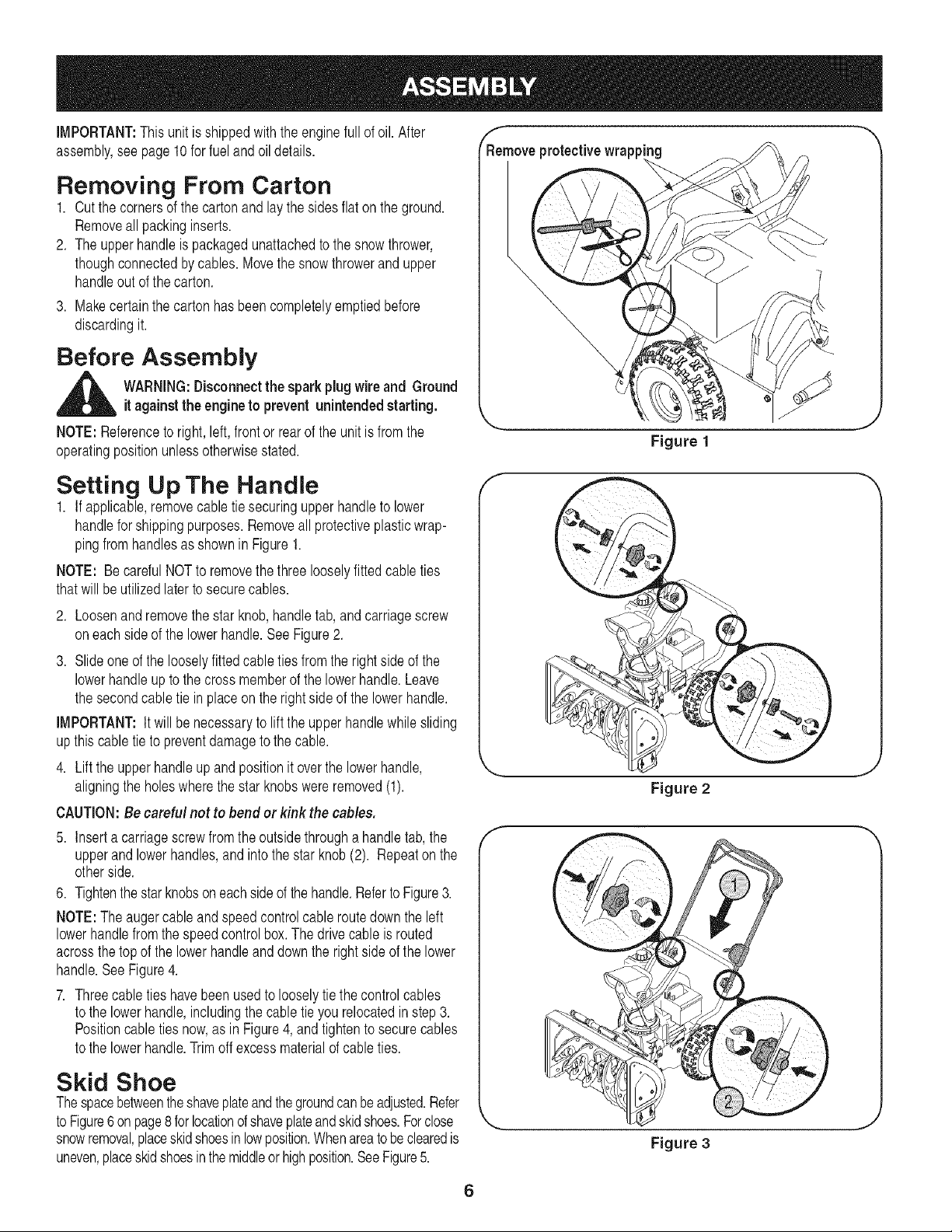
R_emoveprotectivewrapp"_g
\
\
Figure 1
Setting Up The Handle
1. If applicable,removecabletie securingupperhandleto lower
handlefor shippingpurposes.Removeall protectiveplasticwrap-
pingfromhandlesas shownin Figure1.
NOTE: Be carefulNOTto removethe threelooselyfittedcable ties
thatwill beutilizedlaterto securecables.
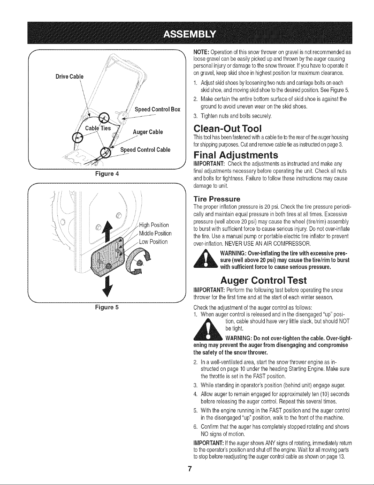
2. Loosenand removethe star knob,handletab, andcarriagescrew
oneach sideof the lowerhandle.SeeFigure2.
3. Slide one of the looselyfittedcableties from the rightside of the
lowerhandleupto the cross memberof the lowerhandle.Leave
the secondcabletie in placeon the rightside of the lowerhandle.
IMPORTANT:It will be necessaryto liftthe upperhandlewhilesliding
upthis cabletie to preventdamagetothe cable.
4. Lift the upperhandleup and positionit overthe lowerhandle,
aligningthe holeswherethe starknobswereremoved(1).
CAUTION:Be careful not to bend or kink the cables,
5. Inserta carriagescrewfromthe outsidethrougha handletab,the
upperand lowerhandles,andintothe star knob(2). Repeatonthe
otherside.
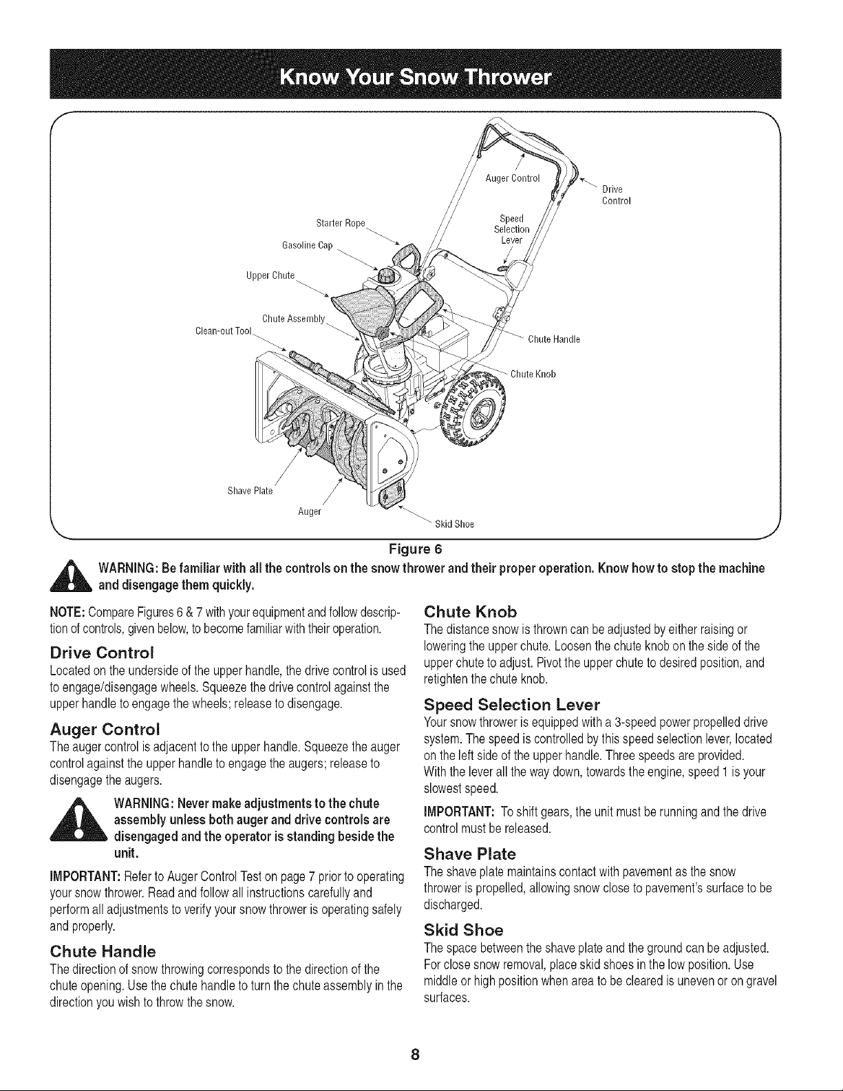
6. Tightenthestarknobsoneachsideof the handle.Referto Figure3.
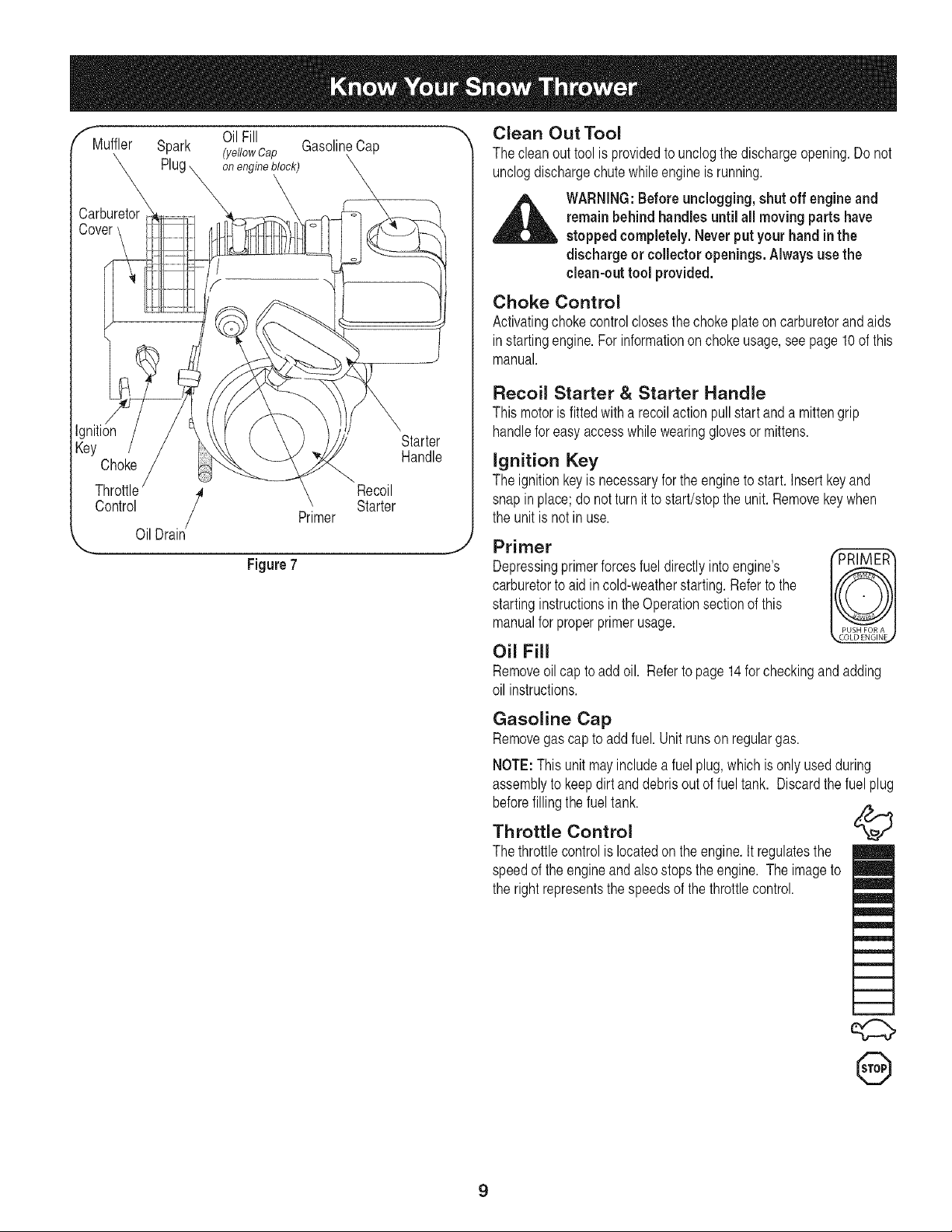
NOTE:The augercableandspeedcontrolcable routedown the left
lowerhandlefromthe speedcontrolbox.The drivecableis routed
acrossthetop of the lowerhandleanddownthe rightside of the lower
handle.SeeFigure4.
7. Threecableties havebeen usedto looselytie the controlcables
to the lowerhandle,includingthe cabletie you relocatedin step 3.
Positioncabletiesnow,as in Figure4,and tightento securecables
to the lowerhandle.Trimoff excessmaterialof cableties.
Skid Shoe
Thespacebetweentheshaveplateandthegroundcanbeadjusted.Refer
to Figure6onpage8 forlocationofshaveplateandskidshoes.Forclose
snowremoval,placeskidshoesin lowposition.Whenareatobe clearedis
uneven,placeskidshoesin themiddleor highposition.SeeFigure5.
Figure 2
Figure 3
6
Drive Cable
/
Speed Control Box
AugerCable
SpeedControl Cable
Figure 4
f
/
/
J
J
Position
MiddlePosition
Figure 5
NOTE:Operationof thissnowthroweron gravelisnot recommendedas
loosegravelcanbeeasilypickedup and thrownbytheaugercausing
personalinjuryordamageto thesnowthrower.Ifyou havetooperateit
on gravel,keepskidshoe inhighestpositionfor maximumclearance.
1. Adjustskidshoesbylooseningtwonutsandcarriageboltson each
skidshoe,andmovingskidshoetothedesiredposition.SeeFigure5.
2. Makecertainthe entirebottomsurfaceof skidshoe is againstthe
groundto avoidunevenwearon theskid shoes.
3. Tightennuts and bolts securely.
Clean-Out Tool
Thistoolhasbeenfastenedwitha cabletietotherearoftheaugerhousing
forshippingpurposes.Cutandremovecabletieasinstructedonpage3.
Final Adjustments
IMPORTANT:Checkthe adjustmentsas instructedand makeany
final adjustmentsnecessarybeforeoperatingthe unit. Checkall nuts
and boltsfor tightness.Failureto followthese instructionsmaycause
damageto unit.
Tire Pressure
The properinflationpressureis 20 psi.Checkthe tire pressureperiodi-
callyandmaintainequalpressureinboth tiresat alltimes.Excessive
pressure(wellabove20 psi) maycause the wheel(tire/rim)assembly
to burstwithsufficientforceto causeseriousinjury.Donot over-inflate
the tire.Usea manualpumpor portableelectrictire inflatorto prevent
over-inflation.NEVERUSEAN AIR COMPRESSOR.
,_ WARNING:Over-inflating the tire with excessivepres-
sure (well above20 psi) may causethe tire/rim to burst
with sufficient forceto cause serious pressure.
Auger Control Test
IMPORTANT:Performthe followingtestbeforeoperatingthe snow
throwerfor the firsttimeandat the start of eachwinterseason.
Checkthe adjustmentof theauger controlas follows:
1. Whenaugercontrol is releasedand in thedisengaged"up"posi-
,_ tion,cableshouldhavevery little slack,but shouldNOT
betight.
WARNING:Do not over-tighten the cable.Over-tight-
eningmay preventthe auger from disengaging and compromise
the safety of the snow thrower.
2. Ina well-ventilatedarea,startthe snow throwerengineas in-
structedon page 10 underthe headingStartingEngine.Makesure
the throttleis set in the FASTposition.
3. Whilestandingin operator'sposition(behindunit)engageauger.
4. Allowauger to remainengagedfor approximatelyten (10)seconds
beforereleasingthe augercontrol.Repeatthisseveraltimes.
5. With the enginerunningin the FASTpositionand the augercontrol
inthe disengaged"up"position,walkto the front of the machine.
6. Confirmthat theauger hascompletelystoppedrotatingandshows
NOsignsof motion.
IMPORTANT:If theaugershowsANYsignsof rotating,immediatelyreturn
to theoperator'spositionandshutofftheengine.Waitforallmovingparts
to stopbeforereadjustingtheaugercontrolcableasshownonpage13.
7
Starter Rope
Gasoline Cap -_
Upper Chute
Drive
Control
Chute Assembly_
Clean-out Tool
Chute Handle
Chute Knob
/
Shave Plate
Anger "_ Skid Shoe
'-.... ,J
Figure 6
_ ARNING:Be familiar with all the controls on the snow thrower and their properoperation. Know how to stop the machine
and disengage them quickly.
NOTE:CompareFigures6 &7 withyourequipmentandfollowdescrip-
tionof controls,givenbelow,to becomefamiliarwiththeiroperation.
Drive Control
Locatedon the undersideof the upperhandle,the drivecontrolis used
to engage/disengagewheels.Squeezethe drivecontrolagainstthe
upperhandleto engagethe wheels;releaseto disengage.
Auger Control
Theaugercontrolis adjacentto the upperhandle.Squeezethe auger
controlagainstthe upperhandleto engagethe augers;releaseto
disengagethe augers.
_ ARNING: Nevermakeadjustments to the chute
assembly unless both auger and drive controls are
disengaged and the operator is standing beside the
unit.
iMPORTANT:Referto AugerControlTeston page7 priorto operating
yoursnowthrower.Readandfollowall instructionscarefullyand
performalladjustmentsto verifyyoursnowthroweris operatingsafely
andproperly.
Chute Handle
Thedirectionof snowthrowingcorrespondsto the directionof the
chuteopening.Usethe chutehandleto turnthe chuteassemblyin the
directionyou wish to throwthe snow.
Chute Knob
The distancesnowis throwncan beadjustedbyeitherraisingor
loweringthe upperchute.Loosenthe chuteknobonthe side of the
upperchuteto adjust.Pivotthe upperchuteto desiredposition,and
retightenthechute knob.
Speed Selection Lever
Yoursnowthroweris equippedwith a 3-speedpowerpropelleddrive
system.Thespeedis controlledbythis speedselectionlever,located
on the left side of the upperhandle.Threespeedsare provided.
Withthe leverallthe waydown,towardsthe engine,speed 1is your
slowestspeed.
iMPORTANT:Toshift gears,the unit mustbe runningand thedrive
controlmustbereleased.
Shave Plate
The shaveplatemaintainscontactwithpavementas the snow
throweris propelled,allowingsnowcloseto pavement'ssurfaceto be
discharged.
Skid Shoe
The spacebetweentheshaveplate and the groundcan be adjusted.
Forclosesnowremoval,placeskidshoesin the lowposition.Use
middleor high positionwhenareato be clearedis unevenor on gravel
surfaces.
8
"_ Clean Out Tool
OilFill
f"fMuffler Spark (ydlowCap GasolineCap
x
on engine block) \
X
Carburetor
Cow
Ignition
Key Starter
Handle
Choke
Throttle / Recoil
Control Primer Starter
OilDrain
,._ j
Figure7
The cleanout tool is providedto unclogthe dischargeopening.Do not
unclogdischargechute whileengine is running.
_ ARNING:Before unclogging, shut off engineand
remain behind handles until all moving parts have
stopped completely. Never put your hand in the
discharge or collector openings. Always use the
clean-out tool provided.
Choke Control
Activatingchoke controlclosesthe choke plateon carburetorandaids
instartingengine.For informationonchokeusage,see page 10 of this
manual.
Recoil Starter & Starter Handle
Thismotoris fittedwitha recoilaction pull startand a mittengrip
handlefor easy accesswhilewearingglovesor mittens.
Ignition Key
The ignitionkeyis necessaryfor the engineto start. Insertkey and
snap inplace;do notturn it to start/stopthe unit. Removekeywhen
the unit is not in use.
Primer
Depressingprimerforcesfuel directlyinto engine's Iv_KI
carburetorto aid incold-weatherstarting.Referto the
startinginstructionsinthe Operationsectionof this
manualfor properprimerusage.
Oil Fill
Removeoil capto add oil. Referto page14for checkingand adding
oil instructions.
Gasoline Cap
Removegas capto add fuel. Unit runson regulargas.
NOTE:Thisunit mayincludeafuel plug,whichis only usedduring
assemblyto keepdirt and debrisoutof fueltank. Discardthe fuel plug
beforefillingthe fueltank.
Throttle Control
The throttlecontrolis locatedonthe engine.It regulatesthe
speedof the engineandalso stopsthe engine. The imageto
the right representsthe speedsof the throttlecontrol.
,:d:::>
@
9
Before Starting Engine
Engine Oil
Theengineisshippedwithoil init.Checktheoil levelbeforefirst use.
Forsubsequentfill-ups,usethe gradeof engineoil specifiedon page
14.To addoil:
1. Removethe dipstickfrom the oil fill. Pourfreshoilslowlythrough
the plug.Replacedipstick.
2. Checkand makesurethat the levelof oil is upto the FULLmarkon
the dipstick.
Gasoline
,_ WARNING:Gasolineisflammable and cautionmust
be used when handlingor storingit. Donot fill fuel
tank while the snow thrower is running, when it is
hot or when it is inan enclosed area.
,_ WARNING:Keepyour snow thrower away from any
open flame or an electricalspark and do not smoke
during fueling.
1. Neverfill the fueltank completely.Fill the tank to no morethan 1/2
inch belowbottomof filler neckto providespacefor expansionof
fuel.
NOTE:Thisunit mayincludea fuel plug,which isonly usedduring
assemblyto keepdirt and debrisout of fuel tank. Discardthefuel plug
beforefillingthe fuel tank.
2. Alwaysuseclean, fresh,unleadedgradeautomotivegasoline.Fill
the fueltankoutdoorsandusea funnelor spoutto preventspilling.
Makesurethatthe containerfrom which you pourthe gasolineis
cleanandfreefromrustor otherforeignparticles.Makesureto
wipeoff anyspilledfuel beforestartingthe engine.
3. At the end of thejob, emptythe fueltank if the snowthroweris not
goingto beusedfor 30 daysor longer.Storegasolinein aclean
containerand keepthe cap in placeon the container.
CAUTION:Never use engineor carburetor cleaner products in
the fuel tank.
To Start Engine
,_ WARNING:Besure no oneother than the operator
is standing nearthe snow thrower while starting or
operating. Do not operate this snow thrower unless
the chute assembly has been properly installedand
is secured.
NOTE: Forlocationof allthe enginecontrolsreferredto inthis section,
referto Figure7.
For A Cold Start
1. Makesurethat auger and drivecontrolsare released.Attachspark
plugwireto sparkplug.
2. Turnfuel valveon, if so equipped.
3. Movethrottlecontrolto FASTposition.
4. Pushkeyintotheignitionslotsothatitsnapsintoplace.Donotturnkey.
5. Rotatechoke controlto FULLchoke position.
6. Pushprimerbuttonwhilecoveringthe vent hole.Removeyour
fingerfromthe primerbetweenprimes.Donot primeif temperature
is above500F;primetwo timesbetween500F and 150F;and
primefour timesbelow150R
7. Graspstarterhandleand pull ropeout slowlyuntilenginereaches
start of compressioncycle (ropewill pullslightlyharderat this
point).Let the roperewindslowly.
8. Pull ropewitha rapid,continuous,full armstroke.Keepinga firm
gripon the starterhandle,let the rope returnto thestarterslowly.
Repeatuntilenginestarts.
9. As the enginewarmsup,rotate thechoke knobslowlyto OFF
position.If theenginefalters, returnto FULLchoke,thenslowly
moveto OFFchokeposition.
10.Allowthe engineto warm up for a fewminutesbecausethe engine
will not developfull poweruntilit reachesoperatingtemperature.
11.Operatethe engineat fullthrottle(FAST)whenthrowingsnow.
For A Warm Start:
1. If restartingan engineafteratemporaryshut-down,rotatechoke
to OFFinsteadof FULLanddo notprime. Pull starterhandleas
instructedbefore.
Before Stopping
1. Runenginefora fewminutesto helpdryoff anymoistureonengine.
2. Toavoidpossiblefreeze-upof the starter,followthesesteps:
Recoil Starter
a. Withthe enginerunning,pullthestarterropewitha rapid,
continuousfullarm strokethreeorfour times.
To Stop The Snow Thrower
1. Tostop the wheels,releasethe drivecontrol.
2. Tostop throwingsnow,releasetheauger control.
3. Tostop engine,pushthrottlecontrolleverto OFF and pull out the
key.Do notturn key.
,_ WARNING:The of muffler and the
temperature
sur-
rounding areas may exceed150° F.Avoid these areas
Clearing The Snow
CAUTION:Checkthe areato beclearedforforeignobjects.Remove
foreignobjects,if any.
1. Start the enginefollowingstartinginstructions.
2. Allowthe engineto warm up for a fewminutesas the enginewill
not developfull poweruntilit reachesoperatingtemperature.
3. Rotatethe chuteassemblyto the desireddirection,awayfrom
bystandersand/or buildings.
4. Makingcertain no bystandersorobstaclesareinfrontof the unit,
squeezetheaugercontrolcompletelyagainstthe upperhandleto
fullyengagethe augers.
5. Whilethe augercontrol is engaged,squeezethe drivecontrol
completelyagainstthe upperhandle toengagethe wheels.Do not
"feather"the drivecontrol.
10
6. As thesnow throwerstartsto move,maintaina firm holdon the
handle,andguidethe snowthroweralongthe pathto becleared.
7. Releasethe augeranddrivecontrolsto stopthe snowthrowing
actionandforwardmotion.
NOTE:Yourunit is equippedwithaclutch inthe transmission.If the
wheelsstopturningwhiletryingto dischargelargevolumesof snow,
immediatelydisengagethe drivecontrolandallowthe rotatingaugers
to dischargesnow fromthe housing.Reducetheclearingwidthand
continueoperation.
8. On eachsucceedingpass,readjustthe chuteassemblyto the
desiredpositionandslightlyoverlapthe previouslyclearedpath.
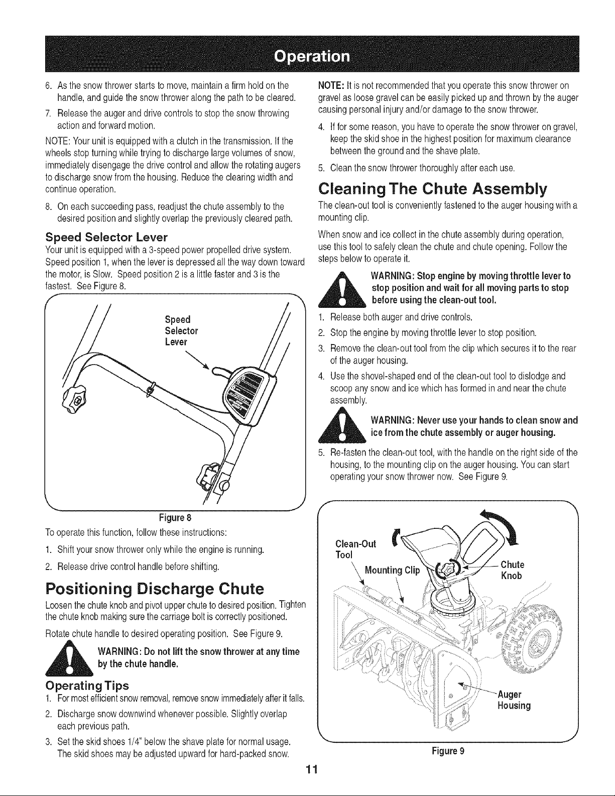
Speed Selector Lever
Yourunit is equippedwith a 3-speedpowerpropelleddrive system.
Speedposition1,whenthe leveris depressedall the way downtoward
the motor,is Slow. Speedposition2 is a littlefasterand3 is the
fastest. See Figure8.
Speed
Selector
Lever
Figure 8
To operatethisfunction,followtheseinstructions:
1. Shift yoursnow throweronly whilethe engineis running.
2. Releasedrive controlhandlebeforeshifting.
Positioning Discharge Chute
Loosenthechuteknobandpivotupperchuteto desiredposition.Tighten
thechuteknobmakingsurethecarriageboltis correctlypositioned.
Rotatechutehandleto desiredoperatingposition. SeeFigure9.
,_ WARNING:Do not lift the snowthrower at any timeby the chutehandle.
Operating Tips
1. Formostefficientsnowremoval,removesnowimmediatelyafterit falls.
2. Dischargesnowdownwindwheneverpossible.Slightlyoverlap
eachpreviouspath.
3. Set theskid shoes 1/4" belowthe shaveplatefor normalusage.
Theskidshoesmaybeadjustedupwardfor hard-packedsnow.
11
NOTE:It is not recommendedthat youoperatethissnowthroweron
gravelas loosegravelcan beeasilypickedup and thrownbythe auger
causingpersonalinjuryand/or damageto the snowthrower.
4. Iffor somereason,you haveto operatethe snowthroweron gravel,
keepthe skidshoe inthe highestpositionfor maximumclearance
betweenthe groundand the shaveplate.
5. Cleanthe snowthrowerthoroughlyaftereachuse.
Cleaning The Chute Assembly
The clean-outtoolis convenientlyfastenedto the auger housingwith a
mountingclip.
Whensnowandice collectinthe chuteassemblyduringoperation,
usethistool to safelyclean thechuteandchuteopening.Followthe
stepsbelowto operateit.
_ WARNING:Stopengineby moving throttle leverto
stoppositionand wait for all moving partsto stop
before using the clean-outtool.
1. Releasebothaugeranddrivecontrols.
2. Stoptheengineby movingthrottleleverto stop position.
3. Removethe clean-outtool from the clipwhich securesit to the rear
of the augerhousing.
4. Usethe shovel-shapedend of the clean-outtoolto dislodgeand
scoopanysnowandice whichhas formedin and nearthe chute
assembly.
_ ARNING:Neveruse your handsto clean snowand
icefrom the chuteassembly or auger housing.
5. Re-fastenthe clean-outtool,withthe handleonthe rightside of the
housing,to the mountingclip onthe augerhousing.Youcan start
operatingyoursnowthrowernow. SeeFigure9.
f --,,,
Knob
_er
Housing
Figure9
J
General Recommendations
1. Alwaysobservesafetyruleswhen performingany maintenance.
2. Thewarrantyon thissnowthrowerdoesnot coveritemsthat have
beensubjectedto operatorabuseor negligence.To receivefull
valuefromthe warranty,operatormust maintainthe snowthrower
as instructedin thismanual.
3. Periodicallycheckall fastenersand hardwareto makesure these
aretight.
_ WARNING: Before servicing,repairing,lubricatingor
inspecting,disengageall controlsand stop engine.
Wait until all moving partshavecometo a complete
stop.Disconnectsparkplugwire and ground itagainst
the engineto preventunintendedstarting.Alwayswear
safetyglassesduringoperation or while performing
anyadjustmentsor repairs.
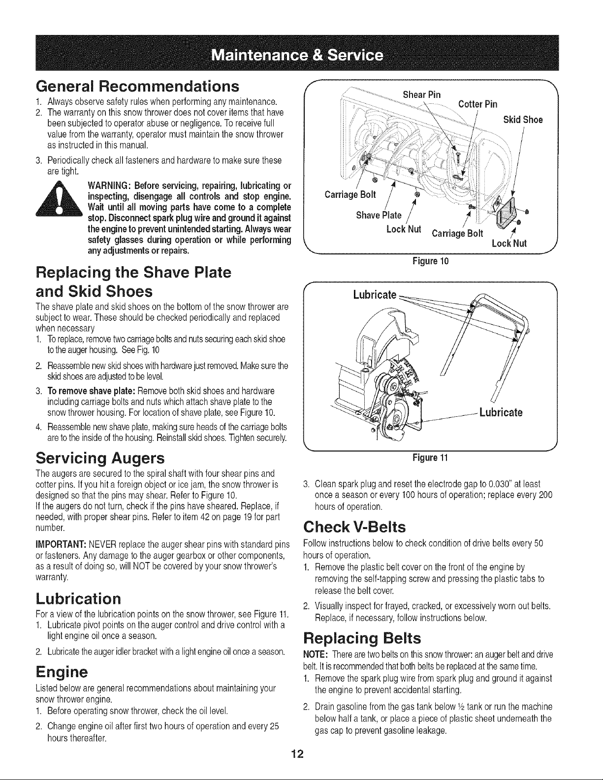
Replacing the Shave Plate
and Skid Shoes
Theshaveplateandskidshoesonthe bottomof the snowthrowerare
subjectto wear.These shouldbe checkedperiodicallyandreplaced
whennecessary
1. Toreplace,removetwo carriageboltsandnutssecuringeachskidshoe
totheaugerhousing.SeeFig.10
2. Reassemblenewskidshoeswithhardwarejustremoved.Makesurethe
skidshoesareadjustedtobelevel.
3. Toremoveshaveplate:Removebothskidshoesand hardware
includingcarriageboltsandnutswhichattachshaveplatetothe
snowthrowerhousing.Forlocationof shaveplate,see Figure10.
4. Reassemblenewshaveplate,makingsureheadsof thecarriagebolts
aretothe insideof thehousing.Reinstallskidshoes.Tightensecurely.
Servicing Augers
Theaugersaresecuredto the spiralshaftwithfourshearpins and
cotterpins.Ifyou hit a foreignobject or icejam, the snowthroweris
designedso thatthe pinsmayshear.Referto Figure10.
If the augersdo notturn,checkif the pins havesheared.Replace,if
needed,withpropershearpins.Referto item42on page19for part
number.
IMPORTANT:NEVERreplacetheauger shearpins with standardpins
orfasteners.Anydamagetothe augergearboxorothercomponents,
as a resultof doing so, will NOTbe coveredby yoursnowthrower's
warranty.
Lubrication
Fora view of the lubricationpointson the snowthrower,see Figure11.
1. Lubricatepivotpointsonthe augercontrolanddrivecontrolwitha
lightengineoiloncea season.
2. Lubricatetheaugeridlerbracketwithalightengineoil oncea season.
Engine
Listedbelowaregeneralrecommendationsabout maintainingyour
snowthrowerengine.
1. Beforeoperatingsnow thrower,checkthe oil level.
2. Changeengineoil afterfirst two hoursof operationandevery25
hoursthereafter.
f
ill .
iii/
iiiii
iiiii
ShearPin
CotterPin
Skid Shoe
Carriage Bolt
Shave Plate /
LockNut CarriageBolt
LockNut
J
Figure10
Lubricate
Figure11
3. Cleanspark plugand resetthe electrodegap to 0.030"at least
once a seasonor every 100hoursof operation;replaceevery200
hoursof operation.
Check V-Belts
Followinstructionsbelowto checkconditionof drive beltsevery 50
hoursof operation.
1. Removethe plasticbeltcoveron the frontof the engineby
removingthe self-tappingscrewand pressingthe plastictabs to
releasethe beltcover.
2. Visuallyinspectfor frayed,cracked,or excessivelywornout belts.
Replace,if necessary,followinstructionsbelow.
Replacing Belts
NOTE:Therearetwobeltsonthissnowthrower:an augerbeltanddrive
belt.It isrecommendedthatbothbeltsbereplacedat thesametime.
1. Removethe spark plugwirefrom spark plug and groundit against
the engineto preventaccidentalstarting.
2. Draingasolinefrom the gas tank belowV2tankor run the machine
belowhalf a tank,or placeapieceof plasticsheetunderneaththe
gas cap to preventgasolineleakage.
12
f
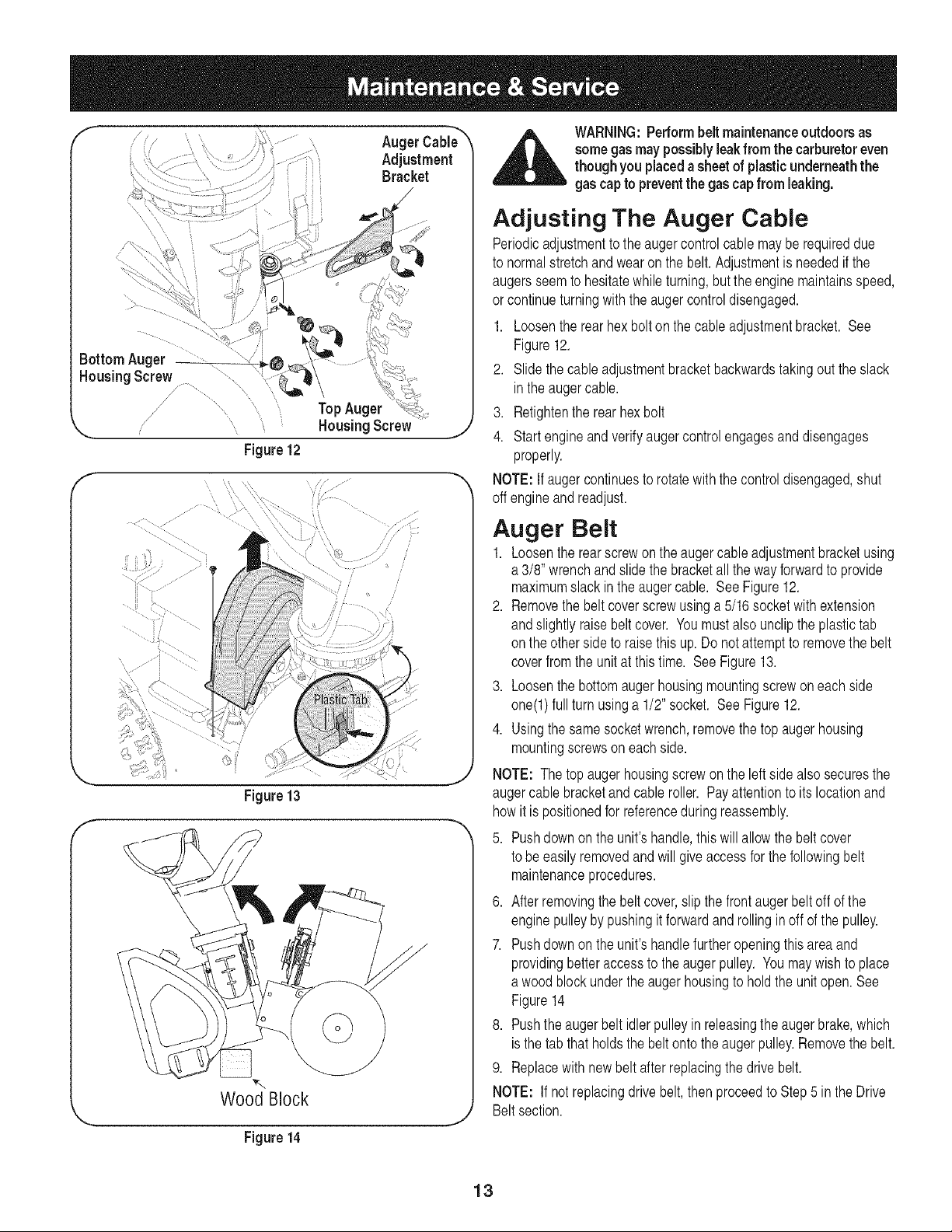
AugerCabi_ "_
Adjustment
Bracket
"-... HousingScrew ,j
Figure12
F ....
Figure 13
Wood Block
Figure14
WARNING:Performbelt maintenanceoutdoors as
somegas maypossiblyleakfrom the carburetoreven
though you placedasheetof plasticunderneaththe
gas cap to preventthe gascap from leaking.
Adjusting The Auger Cable
Periodicadjustmentto the augercontrolcablemayberequireddue
to normalstretchandwearonthe belt.Adjustmentis neededif the
augersseemto hesitatewhile turning,butthe enginemaintainsspeed,
or continueturningwith the augercontroldisengaged.
1. Loosenthe rearhex boltonthe cableadjustmentbracket. See
Figure12.
2. Slidethecable adjustmentbracketbackwardstakingout theslack
inthe augercable.
3. Retightenthe rearhexbolt
4. Startengineandverifyaugercontrolengagesand disengages
properly.
NOTE:If augercontinuesto rotatewith the controldisengaged,shut
off engineand readjust.
Auger Belt
1. Loosenthe rearscrewon the auger cableadjustmentbracketusing
a 3/8' wrenchand slidethe bracketall thewayforwardto provide
maximumslack inthe augercable. See Figure12.
2. Removethe belt coverscrewusinga5/16 socketwithextension
andslightlyraise beltcover. Youmustalso unclipthe plastictab
on theotherside to raisethis up. Donot attemptto removethe belt
coverfromthe unit at thistime. See Figure13.
3. Loosenthe bottomaugerhousingmountingscrewon each side
one(l) fullturn usinga 1/2" socket. SeeFigure12.
4. Usingthe samesocketwrench,removethe topaugerhousing
mountingscrewson eachside.
NOTE: The topaugerhousingscrewonthe leftside alsosecuresthe
augercablebracketandcableroller. Payattentionto itslocationand
howit is positionedfor referenceduring reassembly.
5. Pushdownon the unit'shandle,this willallowthe beltcover
to be easilyremovedand willgive accessfor the followingbelt
maintenanceprocedures.
6. After removingthe belt cover,slip thefrontaugerbelt off of the
enginepulleyby pushingit forwardandrollingin off of the pulley.
7. Pushdownon the unit'shandlefurtheropeningthisareaand
providingbetteraccessto the augerpulley. Youmay wish to place
a woodblock underthe auger housingto holdthe unitopen.See
Figure14
8. Pushthe augerbelt idlerpulleyin releasingthe augerbrake,which
isthe tab that holdsthe beltontothe augerpulley.Removethe belt.
9. Replacewith newbelt after replacingthe drivebelt.
NOTE: If not replacingdrivebelt, thenproceedto Step5 in the Drive
Beltsection.
13
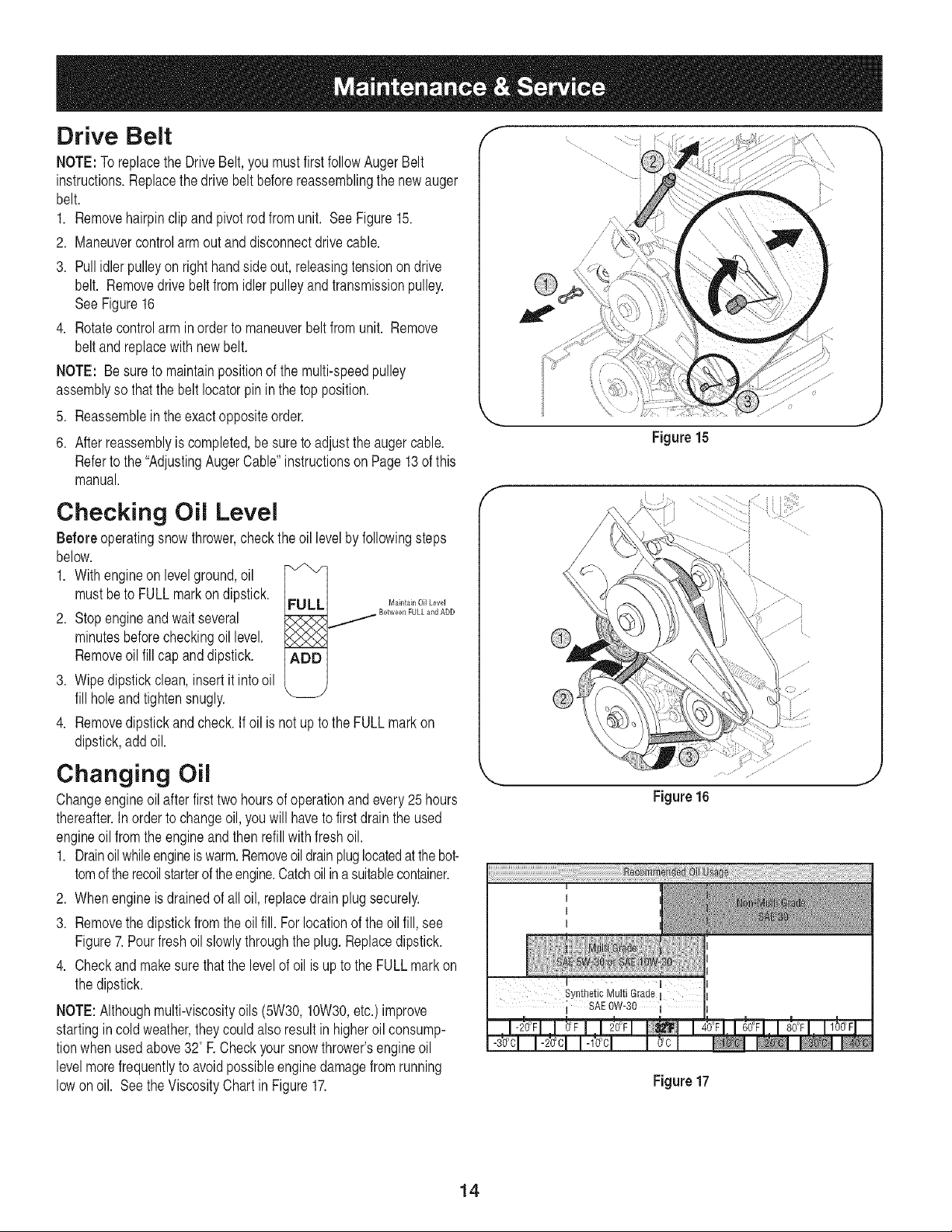
Drive Belt
NOTE:ToreplacetheDriveBelt,you mustfirstfollowAugerBelt
instructions.Replacethedrivebelt beforereassemblingthenewauger
belt.
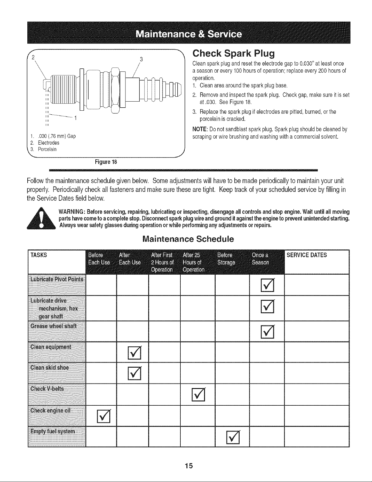
1. Removehairpinclipand pivotrodfromunit. See Figure15.
2. Maneuvercontrolarmout anddisconnectdrivecable.
3. Pull idler pulleyon right handsideout, releasingtensionon drive
belt. Removedrivebelt fromidlerpulleyandtransmissionpulley.
SeeFigure16
4. Rotatecontrolarm in orderto maneuverbelt fromunit. Remove
beltand replacewith newbelt.
NOTE: Be sureto maintainpositionof the multi-speedpulley
assemblyso that the belt Iocatorpin in thetop position.
5. Reassemblein theexactoppositeorder.
6. After reassemblyis completed,be sureto adjustthe auger cable.
Referto the "AdjustingAugerCable"instructionson Page13of this
manual.
Checking Oil Level
Before operatingsnowthrower,checkthe oil levelbyfollowingsteps
below.
1. With engineon levelground,oil
mustbeto FULLmarkon dipstick.
2. Stopengineand wait several
minutesbeforecheckingoillevel.
Removeoil fill cap and dipstick.
3. Wipedipstickclean, insertit intooil
fill holeandtightensnugly.
FULLJ M_int_inOilLevel
_ Between FULL and ADD
ADD
4. Removedipstick and check.If oil is not up to the FULLmark on
dipstick,addoil.
Changing Oil
Changeengineoil after firsttwo hoursof operationand every 25 hours
thereafter.Inorder to changeoil,you will haveto firstdrain the used
engineoil fromthe engineand then refillwith fresh oil.
1. Drainoilwhileengineis warm.Removeoildrainpluglocatedatthe bot-
tomof therecoilstarterof theengine.Catchoilina suitablecontainer.
2. Whenengineis drainedof all oil, replacedrain plugsecurely.
3. Removethe dipstickfrom the oil fill. For locationof theoil fill,see
Figure7.Pourfreshoilslowlythroughtheplug. Replacedipstick.
4. Checkand makesurethat the levelof oil is upto the FULLmarkon
the dipstick.
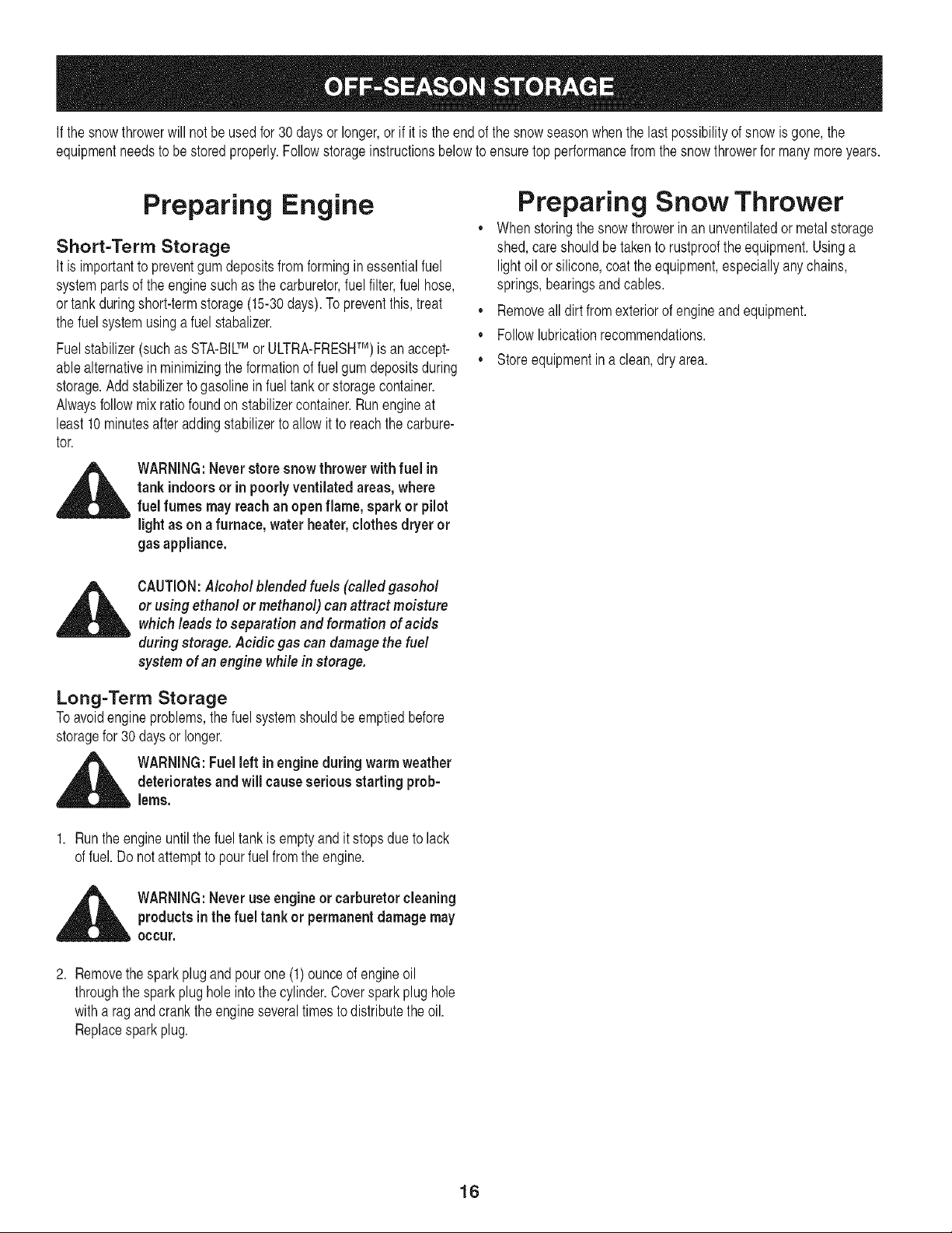
NOTE:Althoughmulti-viscosityoils (5W30,10W30,etc.)improve
startingincold weather,theycouldalso resultin higheroil consump-
tionwhen usedabove32° R Checkyoursnowthrower'sengineoil
levelmorefrequentlyto avoidpossibleenginedamagefrom running
lowon oil. Seethe ViscosityChartin Figure17.
Figure15
Figure16
Synthetic Multi Grade
; SAE 0W-30
1
I
Figure17
14
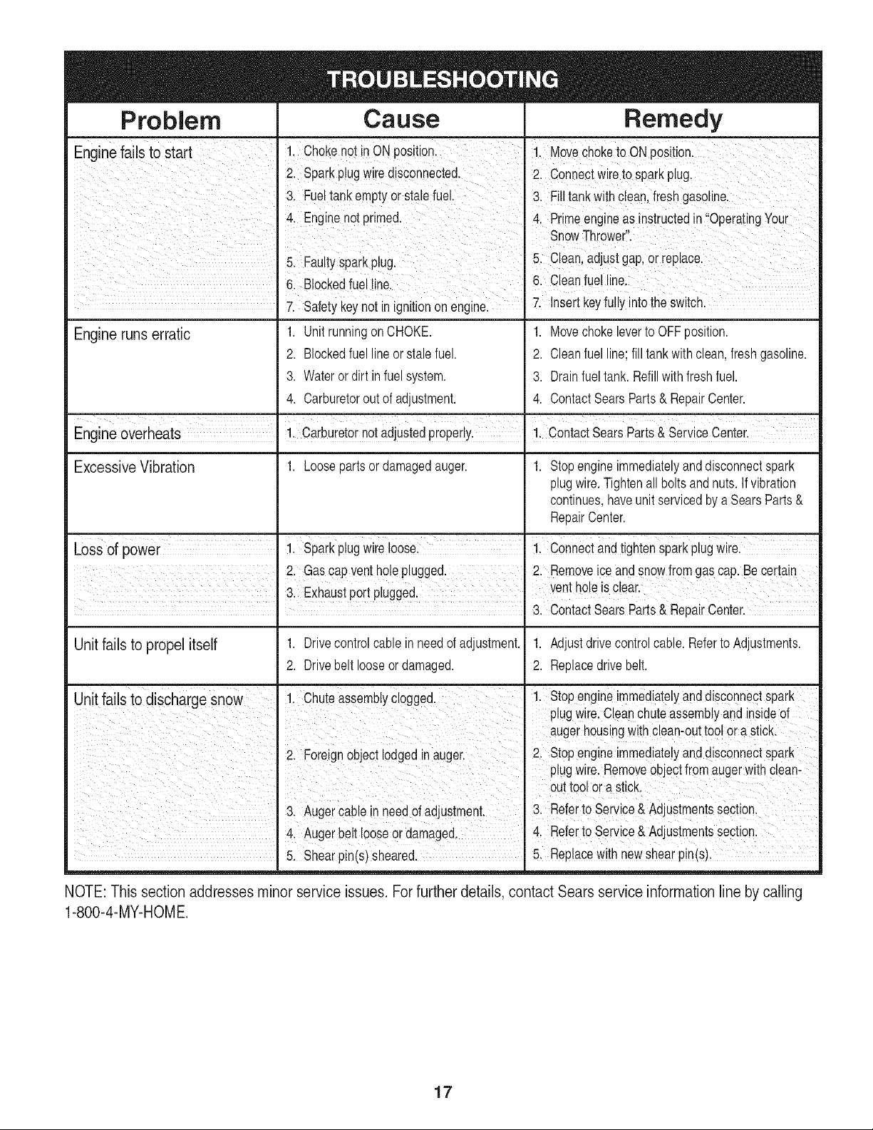
1..030 (.76ram)Gap
2. Electrodes
3. Porcelain
Check Spark Plug
Cleansparkplugandresetthe electrodegap to 0.030"at least once
a seasonor every100hoursof operation;replaceevery200 hoursof
operation.
1. Cleanarea aroundthespark plug base.
2. Removeandinspectthesparkplug. Checkgap, makesureit is set
at .030. SeeFigure18.
3. Replacethe spark plugif electrodesare pitted,burned,orthe
porcelainis cracked.
NOTE:Donot sandblastsparkplug. Sparkplugshouldbecleanedby
scrapingor wirebrushingand washingwitha commercialsolvent.
J
Figure18
Followthe maintenance schedulegiven below. Some adjustmentswill have to be made periodicallyto maintain your unit
properly. Periodicallycheck all fasteners and make sure these are tight. Keeptrack of your scheduled service by filling in
the Service Dates field below.
_ ARNING:Beforeservicing, repairing,lubricating or inspecting,disengageall controlsand stop engine.Wait until all moving
partshavecometo a completestop.Disconnectsparkplugwire and ground it againstthe engineto preventunintendedstarting.
Alwayswearsafetyglassesduringoperation orwhileperformingany adjustmentsor repairs.
Maintenance Schedule
TASKS SERVICEDATES
r--v1
15
If the snowthrowerwill notbe usedfor 30 days or longer,or if it is the end of the snowseasonwhenthe lastpossibilityof snowisgone,the
equipmentneedsto be stored properly.Followstorageinstructionsbelowto ensuretop performancefromthe snow throwerfor manymoreyears.
Preparing Engine
Short-Term Storage
It is importantto preventgumdepositsfrom formingin essentialfuel
systempartsof the enginesuchas the carburetor,fuel filter,fuel hose,
ortankduringshort-termstorage(15-30days).To preventthis,treat
the fuelsystemusingafuel stabalizer.
Fuelstabilizer(suchas STA-BILTM or ULTRA-FRESHTM) is an accept-
ablealternativein minimizingthe formationof fuelgum depositsduring
storage.Addstabilizerto gasolinein fueltankorstoragecontainer.
Alwaysfollowmixratiofoundonstabilizercontainer.Runengineat
least10minutesafteraddingstabilizerto allowit to reachthe carbure-
tor.
WARNING:Neverstoresnowthrower with fuel in
tank indoorsor in poorlyventilatedareas, where
fuel fumes may reachan openflame, sparkor pilot
lightas on afurnace, waterheater,clothesdryeror
gas appliance.
Preparing Snow Thrower
,, Whenstoringthe snowthrowerinanunventilatedor metalstorage
shed,careshouldbetakento rustprooftheequipment.Usinga
light oilor silicone,coat the equipment,especiallyanychains,
springs,bearingsandcables.
,, Removeall dirtfrom exteriorof engineand equipment.
,, Followlubricationrecommendations.
,, Storeequipmentina clean,dry area.
CAUTION:Alcohol blended fuels (called gasohol
or using ethanol or methanol) can attract moisture
which leads to separation and formation of acids
during storage. Acidic gas can damagethe fuel
system of an engine while in storage.
Long-Term Storage
Toavoidengineproblems,thefuel systemshouldbeemptiedbefore
storagefor 30 daysor longer.
,_ WARNING:Fuel left inengineduring warmweather
deteriorates and will causeserious starting prob-
lems.
1. Runthe engineuntilthe fuel tank is emptyand it stops due to lack
of fuel.Do notattemptto pourfuel fromthe engine.
,_ WARNING:Never use engineor carburetorcleaning
productsinthe fuel tank or permanentdamage may
occur,
2. Removethe spark plug and pourone (1)ounceof engineoil
throughthe sparkplugholeintothe cylinder.Coversparkplughole
witha rag and crankthe engineseveraltimesto distributethe oil.
Replacespark plug.
16
Problem Cause Remedy
Enginefails to start i. Chokenot inON position. !. MoveCheketo ONpositionl
2. Spaikp!ugwiredisconneoted. 2. Connectwire to sparkp!ug,
3, Fueltank ernptyorstalefue!. 3. Fill tank with clean,fresh gasoline.
4, Enginenotprimed. 4 Prme engneas instruCtedin QpeiatingYoUr
SnowThrower.
5 Faiit sark lU 5 ceanadjustgaPorrepaee
• y p p g. : .
61 aloCkedfuellinel 6. €leanfue!!ine,
7. Safety keynot in ignitionon engine• 7. Insertkeyfullyintothe switch,
Engine runs erratic
1. Unit runningon CHOKE.
2. Blockedfuel lineor stalefuel.
3. Water or dirt in fuelsystem.
4. Carburetorout of adjustment.
1. Movechokeleverto OFF position.
2. Cleanfuel line;fill tankwith clean, fresh gasoline.
3. Drainfuel tank. Refillwithfreshfuel.
4. Contact SearsParts & RepairCenter.
Engineoverheats 1. Carburetornotadjustedproperly• 1. ContactSearsParts & Service Center•
ExcessiveVibration 1. Loosepartsor damagedauger. 1. Stopengineimmediatelyanddisconnectspark
plugwire.Tightenallboltsandnuts. Ifvibration
continues,haveunit servicedbya SearsParts&
RepairCenter.
Loss of power i. spark p!ugWire!_ose:
i. connect andtighten sparkp!ugWirel
2. Gascapventholeplugged• 2. Removeice and snowfrom gas cap. Be certain
Unit fails to propel itself 1. Drivecontrolcable in need of adjustment.
2. Drivebelt looseor damaged.
3, Contact SearsParts & RepairCenter.
1. Adjustdrive controlcable.Referto Adjustments.
2. Replacedrivebelt.
Unit fails to discharge Snow 1, Chuteassemblyclogged. !. Stopengine immediatelyand disconnectspark
plugwire,O!ganchuteassemb!yand insideof
augerhousingWith€lean-outtool or a sticL
21 Foreigi object iodged n augerl 2, stop engine immediate!yanddisconnectspaik
plugwire.Removeobjectfromaugerwithclean-
out tool ora stick.
& Augeicable in needof adjustment• 3' Referto seivice & Adjustmentssecti°nl
& Auger belt iooseor damaged. 4, Refeitoserviee&Adjustmentssectionl
5, Shearpin(s)sheared. 5. Replacewith newshearpin(s),
NOTE: This section addressesminor service issues. For further details, contact Sears service information line by calling
1-800-4-MY-HOME.
17
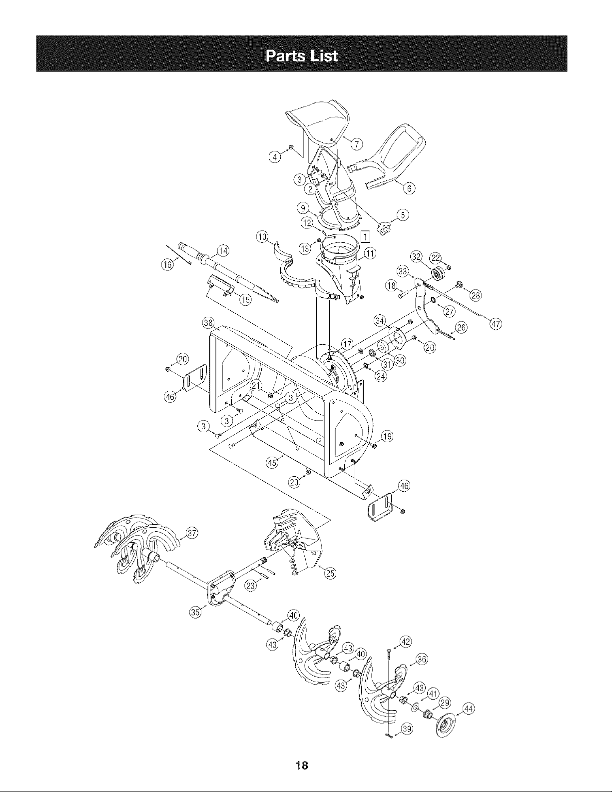
QI
18
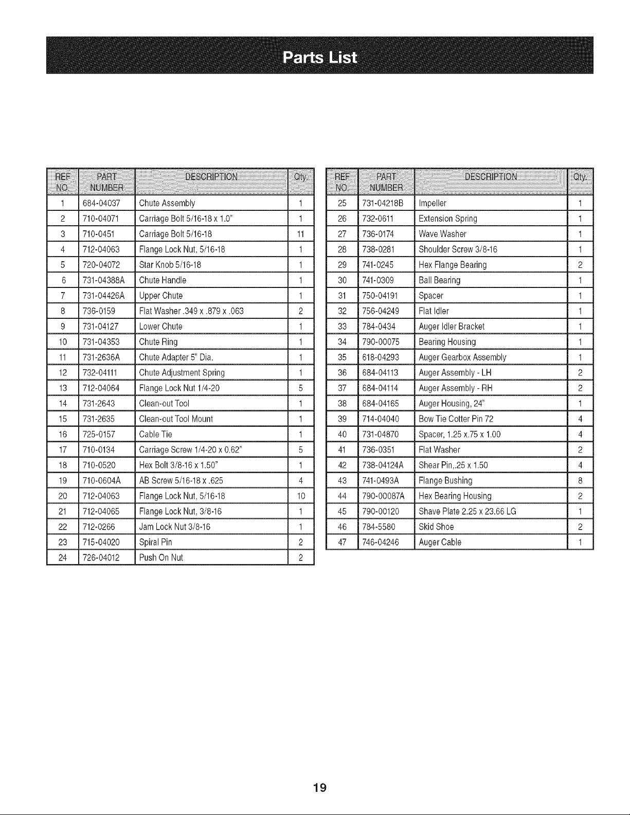
1 684-04037 ChuteAssembly 1 25 731-04218B Impeller 1
2 710-04071 CarriageBolt 5/16-18x 1.0" 1 26 732-0611 ExtensionSpring 1
3 710-0451 CarriageBolt 5/16-18 11 27 736-0174 WaveWasher 1
4 712-04063 FlangeLockNut, 5/16-18 1 28 738-0281 Shoulder Screw3/8-16 1
5 720-04072 Star Knob5/16-18 1 29 741-0245 HexFlangeBearing 2
6 731-04388A ChuteHandle 1 30 741-0309 BallBearing 1
7 731-04426A UpperChute 1 31 750-04191 Spacer 1
8 736-0159 FlatWasher.349 x .879x .063 2 32 756-04249 FlatIdler 1
9 731-04127 LowerChute 1 33 784-0434 Auger IdlerBracket 1
10 731-04353 ChuteRing 1 34 790-00075 BearingHousing 1
11 731-2636A ChuteAdapter8" Dia. 1 35 618-04293 Auger GearboxAssembly 1
12 732-04111 ChuteAdjustmentSpring 1 36 684-04113 AugerAssembly- LH 2
13 712-04064 FlangeLock Nut 1/4-20 5 37 684-04114 AugerAssembly- RH 2
14 731-2643 Clean-outTool 1 38 684-04165 Auger Housing,24" 1
18 731-2635 Clean-outTool Mount 1 39 714-04040 BowTie CotterPin 72 4
16 725-0157 CableTie 1 40 731-04870 Spacer,1.25x.75x 1.00 4
17 710-0134 CarriageScrew1/4-20x 0.62" 5 41 736-0351 FlatWasher 2
18 710-0520 HexBolt 3/8-16x 1.50" 1 42 738-04124A Shear Pin,.25x 1.50 4
19 710-0604A AB Screw5/16-18x .625 4 43 741-0493A FlangeBushing 8
20 712-04063 FlangeLock Nut, 5/16-18 10 44 790-00087A HexBearingHousing 2
21 712-04065 FlangeLock Nut, 3/8-16 1 45 790-00120 Shave Plate2.28 x 23.66LG 1
22 712-0266 Jam Lock Nut 3/8-16 1 46 784-5580 Skid Shoe 2
23 715-04020 SpiralPin 2 47 746-04246 AugerCable 1
24 726-04012 PushOn Nut 2
19
®
[]
[] °'_
/
20
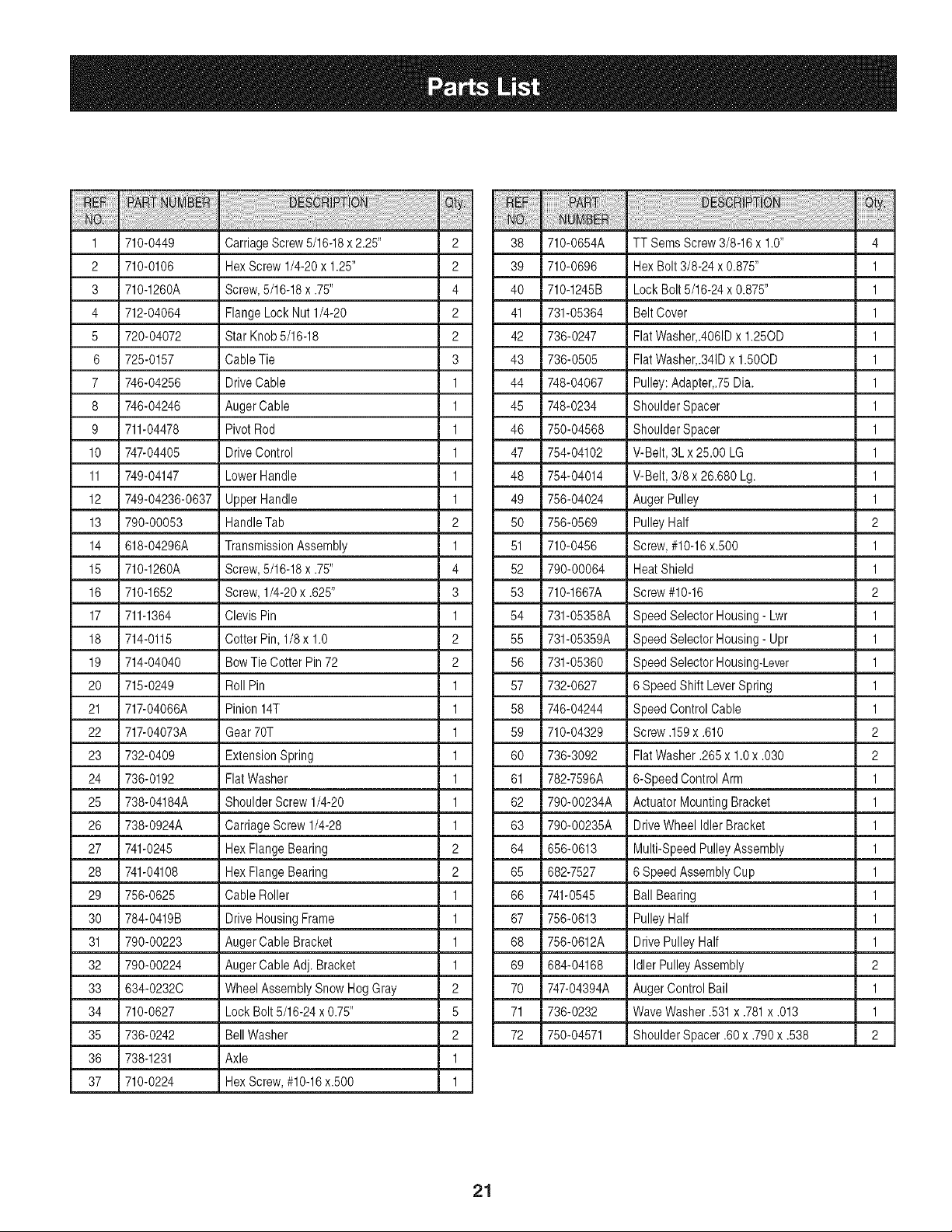
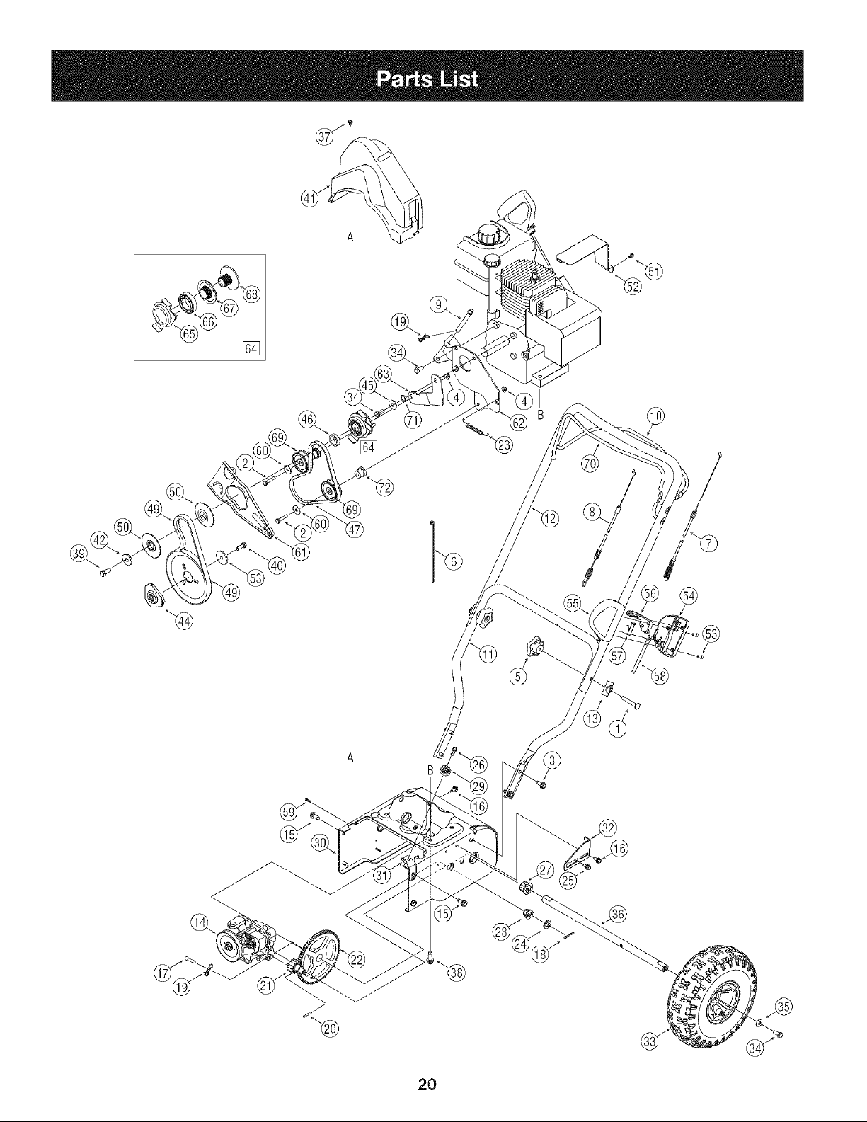
1 710-0449 CarriageScrew5/16-18x 2.25" 2 38 710-0664A TT SemsScrew3/8-16x 1.0" 4
2 710-0106 HexScrew1/4-20x 1.25" 2 39 710-0696 i HexBolt 3/8-24 x 0.875" 1
3 710-1260A Screw,5/16-18x .75" 4 40 710-1245B Lock Bolt 5/16-24x 0.875" 1
4 712-04064 FlangeLock Nut1/4-20 2 41 731-08364 Belt Cover 1
5 720-04072 Star Knob 8/16-18 2 42 736-0247 FlatWasher,.4061Dx 1.250D 1
6 728-0157 Cable Tie 3 43 736-0508 FlatWasher,.341Dx 1.500D 1
7 746-04256 DriveCable 1 44 748-04067 i Pulley:Adapter,.75Dia. 1
8 746-04246 AugerCable 1 45 748-0234 ShoulderSpacer 1
I
9 711-04478 PivotRod 1 46 750-04568 i ShoulderSpacer 1
10 747-04405 DriveControl 1 47 784-04102 i V-Belt,3Lx 28.00 LG 1
I
11 749-04147 LowerHandle 1 48 784-04014 i V-Belt, 3/8 x 26.680 Lg. 1
12 749-04236-0637 UpperHandle 1 49 786-04024 i Auger Pulley 1
13 790-00053 HandleTab 2 50 786-0869 i PulleyHalf 2
14 618-04296A TransmissionAssembly 1 51 710-0466 Screw,#10-16x.500 1
15 710-1260A Screw,5/16-18x .75" 4 52 790-00064 Heat Shield 1
16 710-1652 Screw,1/4-20x .625" 3 53 710-1667A Screw#10-16 2
17 711-1364 Clevis Pin 1 54 731-08388A SpeedSelectorHousing- Lwr 1
18 714-0116 Cotter Pin, 1/8x 1.0 2 58 731-08389A SpeedSelectorHousing- Upr 1
19 714-04040 BowTie Cotter Pin 72 2 56 731-08360 i SpeedSelectorHousing-Lever 1
20 715-0249 Roll Pin 1 67 732-0627 I 6 SpeedShiftLeverSpring 1
21 717-04066A Pinion14T 1 68 746-04244 SpeedControl Cable 1
22 717-04073A Gear70T 1 59 710-04329 Screw.169x .610 2
23 732-0409 ExtensionSpring 1 60 736-3092 FlatWasher.266x 1.0x .030 2
24 736-0192 FlatWasher 1 61 782-7596A i 6-SpeedControlArm 1
28 738-04184A Shoulder Screw1/4-20 1 62 790-00234A i Actuator MountingBracket 1
26 738-0924A CarriageScrew 1/4-28 1 63 790-00238A DriveWheel IdlerBracket 1
27 741-0246 Hex FlangeBearing 2 64 686-0613 Multi-SpeedPulleyAssembly 1
28 741-04108 Hex FlangeBearing 2 68 682-7827 i 6 SpeedAssemblyCup 1
29 756-0625 Cable Roller 1 66 741-0846 Ball Bearing 1
30 784-0419B DriveHousingFrame 1 67 756-0613 i PulleyHalf 1
31 790-00223 AugerCable Bracket 1 68 756-0612A DrivePulley Half 1
32 790-00224 AugerCable Adj. Bracket 1 69 684-04168 i Idler PulleyAssembly 2
33 634-02320 WheelAssemblySnow Hog Gray 2 70 747-04394A Auger ControlBail 1
34 710-0627 Lock Bolt8/16-24x0.75" 5 71 736-0232 l WaveWasher.631x .781x .013 1
35 736-0242 BellWasher 2 72 750-04871 ShoulderSpacer.60 x .790x .838 2
36 738-1231 Axle 1
37 710-0224 Hex Screw,#10-16x.800 1
21
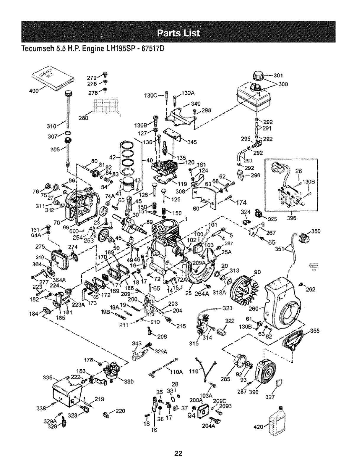
Tecumseh 5.5 H.P.Engine LH195SP- 67517D
i61
i24
i
3_
li81
20
3 _ _
J
287 390
90
/
327
E
_4
262
_/355
22
Tecumseh 5.5 H.P.Engine LH195SP- 67517D
Ref. No. PartNo.
1 36469A
2 26727
5 30969
14 28277
15 31334
16 37729
17 31335
18 651018
19 31426
20 32600
25 36552
25A 35883
30 37842
40 36073
40 36074
40 36075
41 36070
41 36071
41 36072
42 36076
42 36077
42 36078
43 20381
45 32875A
46 32610A
48 37670
49 32654
50 37671
60 29745
64A 8345
65 30200
69 27677A
70 34674C
72 27642
75 27897
80 30574A
81 30590A
82 30591
83 30588A
86 650488
89 610961
90 611195
Description Qty Ref.No. Part Nol Description Qty
Cylinder(Incl.2,20,72& 125) 1 92 650815 BellevilleWasher 1
DowelPin 2 93 650816 FlywheelNut 1
ExtensionCap (1/4-18NPT) 1 100 34443C SolidStateignition 1
Flatwasher 1 101 610118 SparkPlugCover 1
GovernorRod 1 102 651024 SolidStateMountingStud 2
GovernorLever 1 103 651007 Screw,T-15,10-24x 15/16" 2
GovernorLeverClamp 1 110 35182 GroundWire 1
Screw,T-15,8-32 x 19/64" 1 110A 36874 GroundWire- Green,5.5" 1
ThrottleSpring 1 119 36443 * CylinderHeadGasket 1
Oil Seal 1 120 37675 CylinderHead(inc. 130A) 1
BlowerHousingBaffle(Incl.262) 1 125 36471 ExhaustValve(Std.) (Incl. 151) 1
BaffleExtension 1 125 36472 ExhaustValve(1/320% (Incl.151) 1
Crankshaft 1 126 32644A intakeValve(Std.)(Incl. 151) 1
Piston,Pin&Ring Set(Std.) 1 127 650691 Washer 1
Piston,Pin&Ring Set(.0100% 1 130 6021A Screw,5/16-18x 1-1/2" 2
Piston,Pin&Ring Set(.020OS) 1 130A 650694A Screw,5/16-18x 2" 5
Piston& Pin Ass'y.(Std.)(Incl.43) 1 130B 650737 Screw,1/4-20x 1/2" 2
Piston& Pin Ass'y.(.010OS) (Incl.43) 1 130B 650818 Screw,5/16-18x 1-1/2" 1
Piston& Pin Ass'y.(.020OS)(Incl.43) 1 135 35395 ResistorSparkPlug(RJ19LM) 1
RingSet (Std.) 1 150 31672 ValveSpring 2
RingSet (.010OS) 1 151 31673 ValveSpringCap 2
RingSet (.020OS) 1 161 30063 Screw,T-30, 1/4-20x 1/2" 1
PistonPin RetainingRing 2 161 30063 Screw,T-30, 1/4-20x 1/2" 1
ConnectingRod Assy(Incl.46 & 49) 1 169 27234A * ValveCoverGasket 2
ConnectingRod Bolt 2 170 27666 BreatherBody 1
ValveLifter 2 171 31410 BreatherElement 1
Oil Dipper 1 172 34146 ValveCover 1
Camshaft(MCR) 1 173 35350 BreatherTube 1
BlowerHousingExtension 1 174 650128 Screw,10-24x 1/2" 1
Washer 1 178 29752 Nut& LockWasher1/4-28 2
Screw,10-24x 9/16" 1 181 650870 Screw,1/4-28x 1-11/16" 1
• CylinderCoverGasket 1 182 6201 Screw,1/4-28x 7/8" 1
CylinderCover(Incl.75 thru83) 1 183 34583A Choke bracket 1
Oil DrainPlug(Sq. hd., 1/4-18) 2 184 26756 * CarburetorTo intake PipeGasket 1
Oil Seal 1 185 33691 intakePipe 1
GovernorShaft 1 186 32698 GovernorLink 1
Washer 1 200 36677 ControlBracket(Incl.203 thru 209A) 1
GovernorGearAssembly(Incl. 81) 1 203 31342 CompressionSpring 1
GovernorSpool 1 204 651029 Screw,T-IO,5-40x 7/16" 1
Screw,1/4-20x 1-1/4" 7 206 610973 Terminal 1
FlywheelKey 1 206 610973 Terminal 1
Flywheel 1 215 35440 Control Knob 1
23
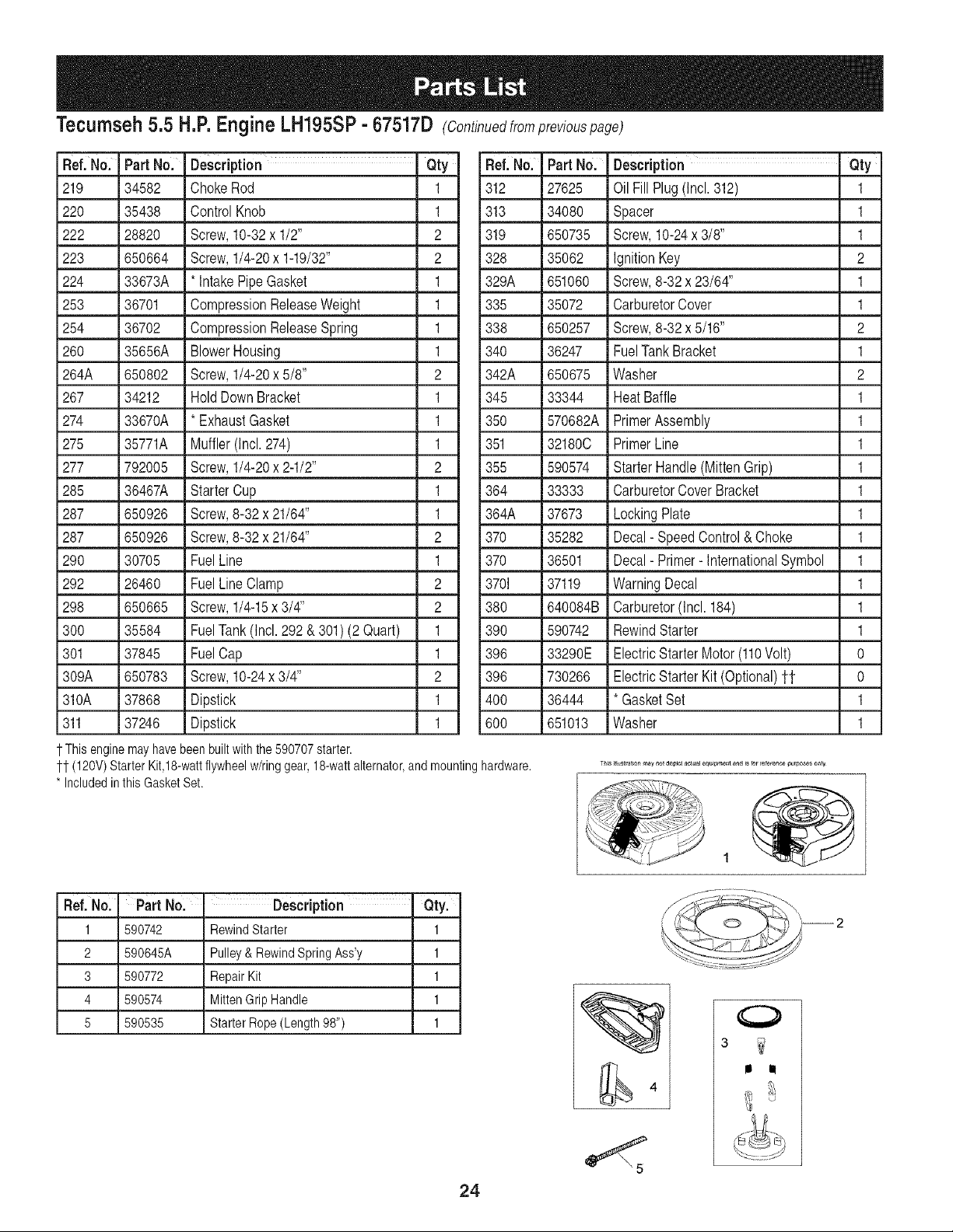
Tecumseh 5.5 H.P.Engine LH195SP- 67517D (Continuedfrompreviouspage)
Ref. No. Part No.
219 34582
220 35438
222 28820
223 650664
224 33673A
253 36701
254 36702
260 35656A
264A 650802
267 34212
274 33670A
275 35771A
277 792005
285 36467A
287 650926
287 650926
290 30705
292 26460
298 650665
300 35584
301 37845
309A 650783
310A 37868
311 37246
Description Qty
ChokeRod 1
ControlKnob 1
Screw,10-32x 1/2" 2
Screw,1/4-20x 1-19/32" 2
* IntakePipeGasket 1
CompressionReleaseWeight 1
CompressionReleaseSpring 1
BlowerHousing 1
Screw,1/4-20x 5/8" 2
HoldDownBracket 1
* ExhaustGasket 1
Muffler(Incl.274) 1
Screw,1/4-20x 2-1/2" 2
StarterCup 1
Screw,8-32x 21/64" 1
Screw,8-32x 21/64" 2
FuelLine 1
FuelLineClamp 2
Screw,1/4-15x 3/4" 2
FuelTank(Incl.292 & 301) (2 Quart) 1
FuelCap 1
Screw,10-24x 3/4" 2
Dipstick 1
Dipstick 1
1-This enginemayhavebeen builtwiththe590707starter.
11 (120V)Starter Kit,18-wattflywheelw/ringgear,18-wattalternator,and
* Includedinthis GasketSet.
mounting
Ref. No. Part No. Description Qty
312 27625 Oil Fill Plug(Incl.312) 1
313 34080 Spacer 1
319 650735 Screw,10-24x 3/8" 1
328 35062 IgnitionKey 2
329A 651060 Screw,8-32x 23/64" 1
335 35072 CarburetorCover 1
338 650257 Screw,8-32 x 5/16" 2
340 36247 FuelTank Bracket 1
342A 650675 Washer 2
345 33344 HeatBaffle 1
350 570682A PrimerAssembly 1
351 321800 PrimerLine 1
355 590574 StarterHandle(MittenGrip) 1
364 33333 CarburetorCoverBracket 1
364A 37673 LockingPlate 1
370 35282 Decal- SpeedControl & Choke 1
370 36501 Decal- Primer-InternationalSymbol 1
3701 37119 WarningDecal 1
380 640084B Carburetor(Incl.184) 1
390 590742 RewindStarter 1
396 33290E ElectricStarter Motor(110Volt) 0
396 730266 ElectricStarter Kit (Optional)tt 0
400 36444 * GasketSet 1
600 651013 Washer 1
hardware.
Ref. No. Part No. - Description " Qty.
1 590742 RewindStarter 1
2 590645A Pulley& RewindSpringAss'y 1
3 590772 RepairKit 1
4 590574 MittenGrip Handle 1
5 590535 Starter Rope(Length98") 1
24
0
3
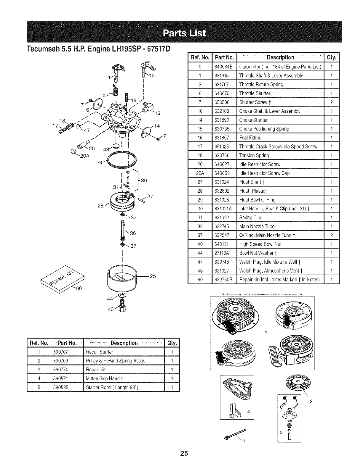
Tecumseh 5.5 H.P.Engine LH195SP- 67517D
Ref. No. Part Nol
0 640084B
1 631615
2 631767
6 640070
7 650506
Description Qty.
Carburetor(Incl. 184of Engine PartsList) 1
ThrottleShaft & LeverAssembly 1
ThrottleReturnSpring 1
ThrottleShutter 1
ShutterScrew 1 2
17,
Ref.No. ' Part No. I Description Qty.
1 590707 RecoilStarter 1
2 590709 Pulley& RewindSpringAss'y. 1
3 590774 RepairKit 1
4 590574 MittenGrip Handle 1
5 590535 Starter Rope( Length98") 1
10 632108 Choke Shaft& LeverAssembly 1
14 631890 Choke Shutter 1
15 630735 Choke PositioningSpring 1
16 631807 FuelFitting 1
17 651025 Throttle Crack Screw/IdleSpeedScrew 1
18 630766 TensionSpring 1
20 640027 IdleRestrictorScrew 1
20A 640053 IdleRestrictorScrewCap 1
27 631024 FloatShaft 1 1
28 632802 Float(Plastic) 1
29 631028 FloatBowlO-Ring1 1
30 631021A InletNeedle,Seat & Clip (Incl.31) 1 1
31 631022 SpringClip 1
36 632745 MainNozzleTube 1
37 632547 O-Ring, MainNozzleTube1- 2
40 640131 HighSpeedBowlNut 1
44 27110A BowlNutWasher1 1
47 630748 WelchPlug,Idle MixtureWell1 1
48 631027 WelchPlug,AtmosphericVent1 1
60 632760B Repairkit (Incl. ItemsMarked1 in Notes) 1
T_isi_l_st_t_on may no1dep_c_ac_aEeq_,e_t _nd,s_orFefere_,__fpo_s only
1
4
Q
2
O
25

26
Manual dei operador
CRAFTSMAN°
5.5 caballos de fuerza
MAQUINA QUITANIEVE DE 24", 4 CICLOS Y 3
VELOCIDADES
NOmero de modelo 247.88455
PRECAUCION: antes de
utilizar este producto, lea
este manual y siga todas
las reglas de seguridad
y las instrucciones de
funcionamiento.
• SEGURIDAD
MONTAJE
OPERACION
MANTENIMIENTO
LISTADO DE PIEZAS
ESPANOL
Sears, Roebuck and Co., Hoffman Estates, IL 60179, EE.UU.
Visite nuestro sitio web: www.sears.corn/craftsrnan NOdeFORMULARIO769-01910B
5/31/2006
Declaraci6ndegarantia..........................PAgina28
Etiquetasdeseguridad...........................PAgina29
Reglasdeoperaci6nsegura..................PAginas30-31
Configuraci6ny ajuste............................PAginas32-33
ConozcasumAquinaquitanieve...........PAgina34-35
Operaci6n...............................................PAgina36-37
Mantenimientoy servicio......................P&gina38-41
Almacenamientofueradetemporadaysoluci6nde
problemas................................................P&gina42-43
NQmerodeservicio...........................Cubiertaposterior
Garanfiade dos aSos parala m_quina quitanieveCraftsman
Durantedos ahosa partirde la fechade compra,siempreque a esta maquinaquitanievese le realiceel serviciode mantenimiento,lubricaci6n
y puestaa puntode acuerdoa las instruccionesdel manualdelpropietario,Searsrepararasin cargocualquierdefectode materialeso manode
obra.Siesta m_.quinaquitanieveCraftsmanse utilizaparaprop6sitoscomercialeso dealquiler,estagaranfiase aplicas61odurante30 diasa
partirde la fecha de compra. Esta garanfiano cubre:
• Elementosdesechablesquese desgastanporel usonormal,incluyendoentreotros,zapatasantideslizantes,placade raspadoy bujias.
• Reparacionesnecesariasdebidoa abusoo negligenciadel operador,incluyendoabolladuradelcig(]ehaly falla pornorealizarmantenimiento
delequipode acuerdocon las instruccionescontenidasenel manualdel propietario.
EL SERVlCIODEGARANTiAEST#,DISPONIBLEPARALOSUSUARIOSQUELLEVENLA M#,QUINAQUITANIEVECRAFTSMANAL
CENTRODE PARTESy REPARACIONSEARSM#,SCERCANODENTRODELOS ESTADOSUNIDOS.
Estagaranfiaes validaOnicamentemientraselproductose utilicedentrode los EstadosUnidos.
PARAUBICAREL CENTRODE PARTESY REPARACIONSEARSM#,SCERCANO0 PARAPROGRAMAREL SERVlCIOTECNICO,SIMPLE-
MENTECOMUNiQUESECONSEARSALTELEFONO1-800-4-MY-HOME@.
Estagaranfialeotorgaderechoslegalesespedficos;ustedtambienpuedetenerotrosderechos,los cualesvarbn de unestadoa otro.
SEARS,ROEBUCKANDCO., D/817WA,HOFFMANESTATES,IL 60179
Acuerdos de protecci6n sobre reparaciones
Felicitacionespor haberrealizadounaadquisici6ninteligente.El
productoCraftsman@queha adquiridoestadisehadoy fabricadopara
brindarmuchosahosde funcionamientoconfiable.
Perocomotodoslosproductosa vecespuederequerirderepara-
clones.Esen esemomentocuandoel disponerde unacuerdode
protecci6nparareparacionesle puedeahorrardineroy problemas.
A continuaci6nsedetallanlos puntosincluidosen el acuerdo:
• Servicioexpertoprestadopor nuestros12.000especialistasen
reparacionesprofesionales
Servicioilimitadosincargoparalas piezasy la manode obra en
todaslas reparacionescubiertas
Reemplazodelproductosi noesposiblerepararelproductocubierto
Descuentode 10%delprecionormaldelservicioy de laspiezas
relacionadascon el mismoque no esten cubiertasporel acuerdo;
adem_ts,10%de descuentodel precionormalde laverificaci6nde
mantenimientopreventivo
Ayudarapidapor tel_fono- asistenciatelef6nicaa cargode un
tecnicodeSearsparalosproductosquerequierenreparaci6na
domicilio,adem_tsde unaprogramaci6nconvenienteparalarepara-
Caballos de fuerza : 5.5
Aceite del motor: SAE 5W=30
Combustible: Gasolina sin plomo
Bujias: Champion@ RJ19LM
Moto: Tecumseh LH195SP
ci6n.Adquieraahoraun acuerdodeprotecci6nparareparacionesy
protejasede problemasy gastosinesperados
Unavezadquiridoel acuerdo,puedeprogramarel serviciocon
tan s61orealizarunaIlamadatelef6nica.PuedeIlamaren cualquier
momentodeldia o dela noche,o programarun servicioen linea.
Searsdisponedemasde 12.000especialistasenreparaciones
profesionalesque tienenaccesoa m_.sde4,5 millonesdepiezas
y accesoriosde gran calidad.Este esel tipo de profesionalismoen
el que puedeconfiar paraquele ayudea prolongarla vida _til del
productorecientementeadquiridoen los ahos por venir,iAdquierahoy
su acuerdodeprotecci6nparareparaciones!
Se aplican determinadas limitaciones y exclusiones.Paraobtener
precios e informaci6nadicional Ilameal 1-800-827-8655.
Servici0 de instalaci6nde Sears
Sideseasolicitarla instalaci6nprofesionalde Searsde aparatos
domesticos,dispositivosparaabrir portones,calentadoresde aguay
otrosarticulosdom_sticosimportantes,en losEstadosUnidosIlame
al 1-800-4-MY-HOME@
N_mero de modelo ......................................................
N_mero de serie ...........................................................
Fecha de compra .........................................................
Registre arriba el n_mero del modelo, el n_mero
de serie y la fecha de compra
28
1 .KEEPAWAYFROMROTATINGIMPELLER
ANDAUGER.CONTACTWITHIMPELLEROR
AUGERCANAMPUTATEHANDSANDFEET,
2. USECLEAN-OUTTOOLTO UNCLOG
DISCHARGECHUTE,
3. DISENGAGECLUTCHLEVERS,STOPENGINE,
ANDREMAINBEHINDHANDLESUNTILALL
MOVINGPARTSHAVESTOPPEDBEFORE
UNCLOGGINGORSERVICINGMACHINE,
4. TO AVOIDTHROWNOBJECTSINJURIES,
NEVERDIRECTDISCHARGEATBYSTANDERS.
USEEXTRACAUTIONWHENOPERATINGON
GRAVELSURFACES.
5. READOPERATOR'SMANUAL.
CLEAN-OUT TOOL m_
ADVERTENCIA
Este sirnboloindicainstruccionesde seguridad
irnportantesque de no seguirse,se podrfa
poner en peligrola seguridadpersonaly/o la
propiedadsuyay de terceros. Lea y sigatodas
las instruccionesen este manual antesde iniciar
la operaci6nde esta rn_.quina.Encaso de no
seguirestas instruccionespodria provocar
lesiones personales.Cuandovea este sirnbolo.
SIGA LA ADVERTENCIA.
Su responsabilidad
Esta rn_.quinaelectrica s61opueden usarla las
personas que Jean,cornprendany respeten las
advertencias e instrucciones que aparecen en
este manual yen la rn_.quina.
AVOIDSERIOUSINJURYFROMTIRE/RIM EXPLOSION.
TO PREVENT0VER-INFLATION:
+ USE A MANUAL PUMP OR PORTABLEELECTRIC
TIRE INFLATOR.
+ NEVER USEAN AIR COMPRESSOR.
* INFLATETIRE TO 20 PSI.
Herramientade
npieza del canal
J
Hayunaherramientade limpiezadeJcanalajustadaa lapartesuperior
delacajadelabarrenacon unpasadordeensamblado.Laherramienta
est,.disehadaparalimpiarel hieloy la nievedel montajedeuncanal.
Esteproductose sujeta medianteunaunbn de cableen laf_.brica.
Cortela uni6nde cableantes deoperarlam_tquinaquitanieve.
,_ ADVERTENCiA: nunca use sus manos
para Jiberar un montaje de canal tapado.
-- Apague el motor y permanezca detr_s de
las manijas hasta que todas Jaspartes
m6viJes se hayan detenido antes de utiJizar
la herramienta de limpieza para limpiar el
montaje del canal.
29
ADVERTENCIA:elescapedelmotordeesteproducto,algunosdesuscornponentesy algunoscorn-
ponentesdelvehiculocontienenoernitenproductosquirnicosqueelestadodeCaliforniaconsideraque
puedenproducircancer,defectosdenacirnientouotrosproblemasreproductivos.
PELIGRO:Estarn_.quinaest,.diseSadaparaserutilizadarespetandolasreglasdeseguridadcontenidasenestemanual.
AIigualqueconcualquiertipodeequipoelectrico,undescuidoo errordepartedeloperadorpuedeproducirlesiones
graves.Estarn_.quinaescapazdearnputarrnanosy piesy dearrojarobjetoscongranfuerza.Denorespetarlasinstruc-
clonesdeseguridadsiguientessepuedenproducirlesionesgravesolarnuerte.
ADVERTENClA:estesirnboloindicainstruccionesdeseguridadirnportantesquedenoseguirse,se
podriaponerenpeligrola seguridadpersonaly/olapropiedadsuyay deterceros.Leay sigatodaslas
instruccionesenestemanualantesdeiniciarlaoperaci6ndeestarn_.quina.Encasodenoseguirestas
instruccionespodriaprovocarlesionespersonales.CuandoveaestesirnboloSlGALAADVERTENCIA.
Suresponsabilidad:estarn_.quinael_ctricas61opuedenusarlalaspersonasquelean,cornprendany respetenlasad-
vertenciase instruccionesqueaparecenenestemanualy enlarn_.quina.
Preparativos
1. Inspeccioneminuciosamenteel a.readondeutilizarAelequipo.Saquetodos
losfelpudos,periodicos,trineos,tablas,cablesy otrosobjetosextraSoscon
los quepedriatropezaro que podrianserarrojadosporla barrena/ motor.
2. Paraprotegerselos ojosutilice siempreanteojoso antiparrasde
seguridadmientrasopera la mAquinao mientrasla ajustao repara.Los
objetos arrojadosque rebotanpuedenlesionargravementelavista.
3. Nooperela mAquinasinla vestimentaadecuadaparaestaral aire libre en
invierno.No utilicealhajas,bufandaslargasu otras prendassueltasque
podrfanenredarseen las partesm6viles.Utilice un calzadoespecialpara
superficiesresbaladizas.
4. Useunprolongadory untomacorrientede tres cablescon conexi6na
tierra paratodas las unidadescon motoresde encendidoelectrico.
5. Ajuste laalturadela caja del tomacorrientepara limpiarla grava o las
superficiescon piedrastrituradas.
6. Desengranetodas las palancasde controlantes de arrancarel motor.
7. Nuncaintenterealizarajustesmientrasel motorestAen marchaexcepto
en loscases especificamenterecomendadosen el manualdel operador.
8. Dejequeel motory la maquinaseadaptena la temperaturaexteriorantes
de comenzara sacarla nieve.
9. ParaevitarlesionespersonalesodaSosmaterialesseasumamentecuidadosoal
manipularlagasolina.Lagasdinaesaltamenteinflamableysusvaporespuedencausar
explosiones.Sepuedelesionargravementesiderramagasolinasobreustedosobrela
ropayaquesepuedeprenderfuego.IAveselapiely cambiesederopadeinmediato.
a. Utilicesale recipientesparagasolinaautorizados.
b. Apaguetodosloscigarrillos,cigarros,pipasy otrasfuentesde combustion.
c. Nuncacarguecombustibleen la mAquinaen un espaciocerrado.
d. Nuncasaque la tapa del gas niagreguecombustiblemientrasel motor
estAcaliente o en marcha.
e. Dejeque el motorse enfriepor Io menos dos minutosantesde volvera
cargar combustible.
f. Nuncarecargueeltanque de combustible.Lleneeltanque noma.s
de 1/2 pulgadapor debajode la basedel cuello del filtro para dejar
espacioparala dilataciondel combustible.
g. Vuelvaa colocar latapa de lagasolinay ajustelabien.
h. Limpiela gasolinaderramadasobreel motory el equipo.Trasladela
maquinaa otra zona. Espere5 minutosantesde encenderel motor.
i. Nuncaalmacenela ma.quinao el recipientede combustibleen un
espaciocerradodondehayafuego, chispaso luz piloto (porejemplo,
homes,calentadoresde agua, calefactores,secadoresde ropa,etc.).
j. Dejequela maquinase enfrie per Iomenos5 minutosantes de
guardarla.
Capacitaci6n
1. Lea,entienday cumplatodaslas instruccionesincluidasenla ma.quinay
en los manualesantes demontarlay utilizarla.Guardeeste manualen un
lugarseguroparaconsultasfuturasy regulares,asi comoparasolicitar
repuestos.
2. Familiaricesecon todos loscontrolesy sufuncionamientoapropiado.Sepa
comodetenerla maquinay camedesengranarloscontrolesrapidamente.
3. Nopermitanuncaque losnidosmenoresde 14aSosutilicenestamaquina.
Los ni5os de 14 a5osy masmayoresdebenleery comprenderlasinstruc-
clonesde funcionamientoy las reglasde seguridadcontenidasen este
manual,y tambiendeben sercapacitadosy estar supervisadosporunode
lospadres.
4. Nunca permitaque losadultosutilicenesta maquinasin recibirantesla
instrucci6napropiada.
5. Los objetosarrojadosporla ma.quinapuedenproducirlesionesgraves.
Planifiqueel patronenel queva air arrojandonievepara evitarque la
descargade materialse realicehacialos caminos,los observadores,etc.
6. Mantengaa losobservadores,ayudantes,mascotasy niSospor Iomenosa
75 pies de la maquinamientrasla mismaestaen funcionamiento.Detenga
la maquinasi alguienentraenla zona.
7. Seaprecavidopara evitarpatinarsee caerseespecialmentecuandoopera
la maquinaen reversa.
30
Operaci6n
1. No pongalasmanos o los piescerca de las piezasrotatorias,en la caja
de la barrena/ motoro en el montajedel canalde descarga.Elcontacto
con las piezasrotatoriaspuedeproducirla amputacionde manosy pies.
2. La palancadecontroldela barrena/ motores un dispositivodeseguri-
dad. Nuncapase poralto sufuncionamiento.Dehacerlola operaci6nde
la maquinaes riesgosay puedeocasionarlesiones.
3. Laspalancasde controldebenfuncionarbienenambasdireccionesy
regresarautomaticamentea laposicionde desengranecuandose las suelta.
4. Nuncaoperelamaquinasifaltaunmontajedelcanalo sielmismoestAda_ado.
Mantengatodoslosdispositivosdeseguridadensulugaryen funcionamiento.
5. Nunca enciendaun motoren espacioscerradoso en unazonacon poca
ventilacion.Elescapedel motorcontienemonoxidodecarbono,ungas
inodoroy letal.
6. No utilicela mAquinabajola influenciadel alcoholo las drogas.
7. El silenciadory el motorse calientany puedenproducirquemaduras.No
lostoque.
8. Seasumamenteprecavidocuandooperela maquinasobre una superficie
con grava o cuandola cruce. Mantengasealerta por si se presentan
peligrosocultoso transito.
9. Tengacuidadocuandocambiede direcci6n o cuandooperela maquina
en pendientes.
10.Planifiqueel patronen el que va air arrojandonieveparaevitar que
la descargade materialse produzcahacialas ventanas,las paredes,
los automoviles,etc.y evitar asi posiblesdahos materialeso lesiones
producidaspor los rebotes.
11.Nuncadirijala descargahacialos ni_os,los observadoresy lasmascotas
ni dejeque nadiese pare delantede la maquina.
12.No sobrecarguela capacidaddela maquinatratandode sacarla nieve
muyrApidamente.
13.Nuncaopereestamaquinasin buenavisibilidado iluminacion.Siempre
debe estarsegurode queestabien afirmadoy sostengabienlas manijas.
Camine,nuncacorra.
14.Corte lacorrientea la barrena/ motorcuandotransportelamaquinao
cuandola mismano esta en uso.
15.Nuncaoperela maquinaa altavelocidad dedesplazamientosobre
superficiesresbaladizas.Mirehacia abajoy haciaatras y tenga cuidado
cuandovayamarchaatrAs.
16.Si la mAquinacomenzaraavibrar de maneraanormal,detengael motor,
desconecteel cablede la bujia y pongalade maneraque hagamasa
contrael motor.Inspeccionela maquinaminuciosamentepara versiesta
da_ada.Reparetodos los da_osantes de encendery operarla maquina.
17.Desengranetodas laspalancasde control y detengael motorantesde
dejar la posici6nde operacion(detrasde las manijas).Esperea que la
barrena/ motorse detengapor completoantes de destaparel montajedel
canalo realizarajustese inspecciones.
18.Nuncapongalas manosen las aberturasde descargao de recoleccion.
Utilice siemprela herramientade limpiezaque se adjuntaparadestapar
la aberturade descarga. Nodestapeel montajedelcanal mientrasel
motorestaen funcionamiento.Antes de destaparlo,apagueel motory
permanezcadetrasde las manijashastaquetodas las partes m6vilesse
hayandetenido.
19.Usesolo unionesy accesoriosaprobadospor elfabricante(porejemplo,
pesaspara las ruedas,cadenaspara los neumaticos,cabinas,etc.).
20.Si se presentansituacionesque no estanprevistasen estemanual,sea
cuidadosoy useel sentidocomun.Contactecon su centrode servicio
Sears paraobtener ayuda.
IVlantenimiento y almacenamiento
1. Nuncamanipulelosdispositivosde seguridaddemaneraimprudente.
Controleperi6dicamenteque funcionende formaadecuada.Remitasea
las seccionesdemantenimientoy ajustede estemanual.
2. Antesde realizarlalimpieza,repararo revisarla maquina,desengrane
todas las palancasde controly detengael motor.Esperea que la barrena
/ motorse detengaporcompleto.Desconecteelcable dela bujfay
pongalode maneraque hagamasacontra el motorparaevitar quese
enciendade maneraaccidental.
3. Controlefrecuentementequetodos los pernosy tornillosesten bien
ajustadosparacomprobarquela maquinaseencuentraen condiciones
segurasde funcionamiento.Asimismo,realiceuna inspecci6nvisual de la
maquinaparacontrolarsi la mismaestadahada.
4. Nocambiela configuraciondel reguladordel motorni aceleredemasiado
el mismo. El reguladorcontrola lavelocidadmaximasegura de operacion
del motor.
5. Lasplacasde raspadoy laszapatasantideslizantesqueseusanconlamaquina
quitanievesedesgastany seda_an.Paraprotegersuseguridad,verifique
frecuentementetodosloscomponentesy reemplaceloss61oconpartesdelos
fabricantesdeequiposoriginales(OEM)."Lautilizaci6ndepiezasquenocumplan
conlasespecificacionesdeequiposoriginalespodrfatenercomoresultadoun
rendimientoincorrecto,y ademaslaseguridadpodrfaestarcomprometida"
6. Reviselos controlesperiodicamenteparaverificarque engraneny desen-
granen adecuadamentey ajqstelossi esnecesario.Consultela seccion
de ajustesen estemanualdel operadorparaobtenerinstrucciones.
7. Mantengao reemplacelas etiquetasde seguridad e instruccionessegun
sea necesario.
8. Respetelas normasreferentesa ladisposicioncorrectay las reglamenta-
cionessobregas,combustible,etc.paraprotegerel medicambiente.
9. Antesde almacenarla maquinaenciendalaunos minutosparasacar la
nieveque hayaquedadoen la mismay paraevitarasi que secongele la
barrena/ motor.
10.Nuncaalmacenela maquinao el recipientede combustibleen un espacio
cerradodondehayafuego,chispaso luzpiloto como porejemplo,
calentadoresde agua,hornos,secadoresde ropa,etc.
11.Consultesiempreel manualde funcionamientoparaconocer lasinstruc-
cionesadecuadaspara el almacenamientofuerade temporada.
No modifique el motor
Paraevitarlesionesgraveso la muerte,no modifiqueelmotorbajoninguna
circunstancia.Si cambialaconfiguraci6ndel reguladorel motorpuededescon-
trolarsey operara velocidadesinseguras.Nuncacambielaconfiguracionde
fabricadel reguladordel motor.
Aviso refetido a emisiones
Losmotoresqueestancertificadosy cumplenconlas regulacionesdeemisio-
nesfederalesEPAy deCaliforniapara SORE(EquiposSmall Off RoadEquip-
ment)estancertificadospara operarcon gasolinacomqn sinplomoy pueden
incluirlossiguientessistemasde controldeemisiones:Modificaci6nde motor
(EM)y catalizadorde tresvias (TWC)siesta equipadode esa manera.
Calcomania de identificaci6n del motor
Estacalcomaniaindicael nqmerodel modelodel motor,las especificacionesy
lafechade fabricacion.Porfavor,mirela calcomanfaen el motorde su equipo
y registreesa informacionpara referenciafutura.
Lacalcomaniade identificaci6ndel motortambienincluyeespecificaciones
sobre el periodode vida qtildel motorrelacionadocon las emisiones.Este
periodoestarelacionadocon lavida t_tilen conformidadcon lasemisiones
segqn IocertificadoporEPAy/o CARB.Parahallarla especificaci6ndel
periododevida t]tildel motor,por favorlea lacalcomaniadel motory ub.ique
laletra(entre comillas)entrelaspalabrasModeradoy Periodode Vida Util.
Conecteunade lassiguientesletrascon la letra impresaen su calcomania.
Porejemplo,a los modelosHMSK80 se losdesignacomo:
"C"-- 250horas
"B"-- 500 horas
"A"-- 1000horas
31
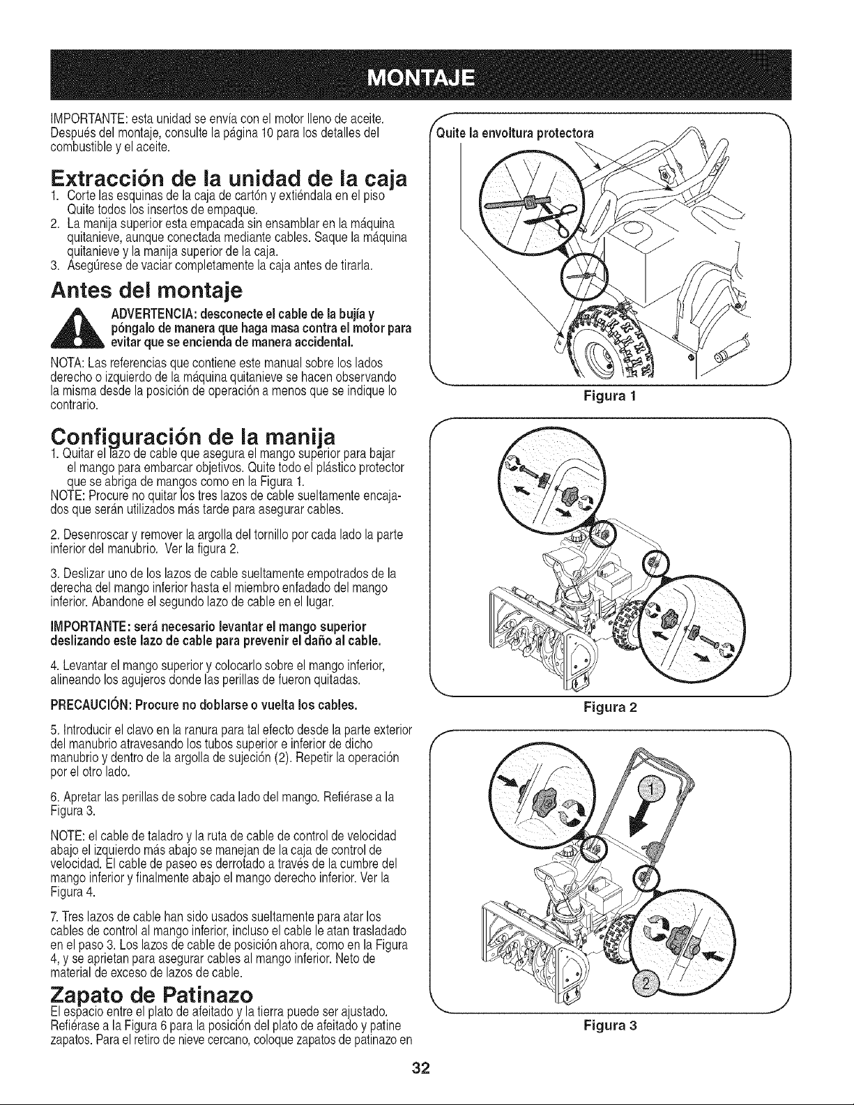
IMPORTANTE:estaunidadse enviacon el motorIlenode aceite.
Despuesdelmontaje,consultela p_tgina10paralos detallesdel
combustibley elaceite.
Extracci6n de ia unidad de la caja
1. Corte lasesquinasde lacajade cart6ny extiendalaen el piso
Quitetodoslosinsertosdeempaque.
2. La manijasuperiorestaempacadasin ensamblaren la m_.quina
quitanieve,aunqueconectadamediantecables.Saquela m_tquina
quitanievey la manijasuperiorde la caja.
3. AsegOresede vaciarcompletamentela cajaantesde tirarla.
Antes del montaje
_ DVERTENCIA:desconecteel cablede la bujia y
p6ngalode maneraque hagamasacontrael motor para
evitarquese enciendade maneraaccidental.
NOTA:Las referenciasquecontieneestemanualsobre loslados
derechoo izquierdode la m_.quinaquitanievese hacenobservando
la mismadesdela posici6nde operaci6na menosquese indiqueIo
contrario.
Configuraci6n de ia manija
1.Quitarell_zo de cableque asegurael mangosuperiorparabajar
el mangopara embarcarobjetivos.Quitetodo el pl_tsticoprotector
quese abrigade mangoscomoen la Figura1.
NOTE:Procurenoquitarlostres lazosde cablesueltamenteencaja-
dosqueser_.nutilizadosm_tstarde paraasegurarcables.
2. Desenroscary removerla argolla del tornillopor cadalado la parte
inferiordel manubrio. Ver la figura2.
3. Deslizarunode los lazosde cable sueltamenteempotradosde la
derechadel mangoinferiorhastael miembroenfadadodelmango
inferior.Abandoneel segundolazode cableenel lugar.
IMPORTANTE:ser_ necesariolevantarel mango superior
deslizando este lazode cableparaprevenirel dafio al cable.
4. Levantarel mangosuperiory colocarlosobreel mangoinferior,
alineandolos agujerosdondelas perillasde fueronquitadas.
PRECAUClON:Procureno doblarse o vueltalos cables.
5. Introducirel clavoen laranuraparatal efectodesdelaparte exterior
delmanubrioatravesandolostubossuperiore inferiorde dicho
manubrioy dentrodela argollade sujeci6n(2). Repetirlaoperaci6n
porel otro lado.
6. Apretarlasperillasdesobrecada ladodel mango.Refierasea la
Figura3.
NOTE:el cablede taladroy la ruta de cable de controlde velocidad
abajoel izquierdom_tsabajose manejande la caja de controlde
velocidad.Elcablede paseoes derrotadoa travesde lacumbredel
mangoinferiory finalmenteabajoel mangoderechoinferior.Verla
Figura4.
7.Treslazosdecable hansido usadossueltamenteparaatarlos
cablesde controlal mangoinferior,inclusoel cable le atantrasladado
enel paso3. Loslazosde cablede posici6nahora,como en la Figura
4, y se aprietanparaasegurarcablesal mangoinferior.Nerode
materialde excesode lazosde cable.
Zapato de Patinazo
Elespacioentreel platode afeitadoy latierrapuedeserajustado.
Refierasea la Figura6para laposici6ndelplatode afeitadoy patine
zapatos.Parael retirode nievecercano,coloquezapatosde patinazoen
Q_uitela envolturaprotectora
\
J
Figura 1
Figura 2
Figura 3
32
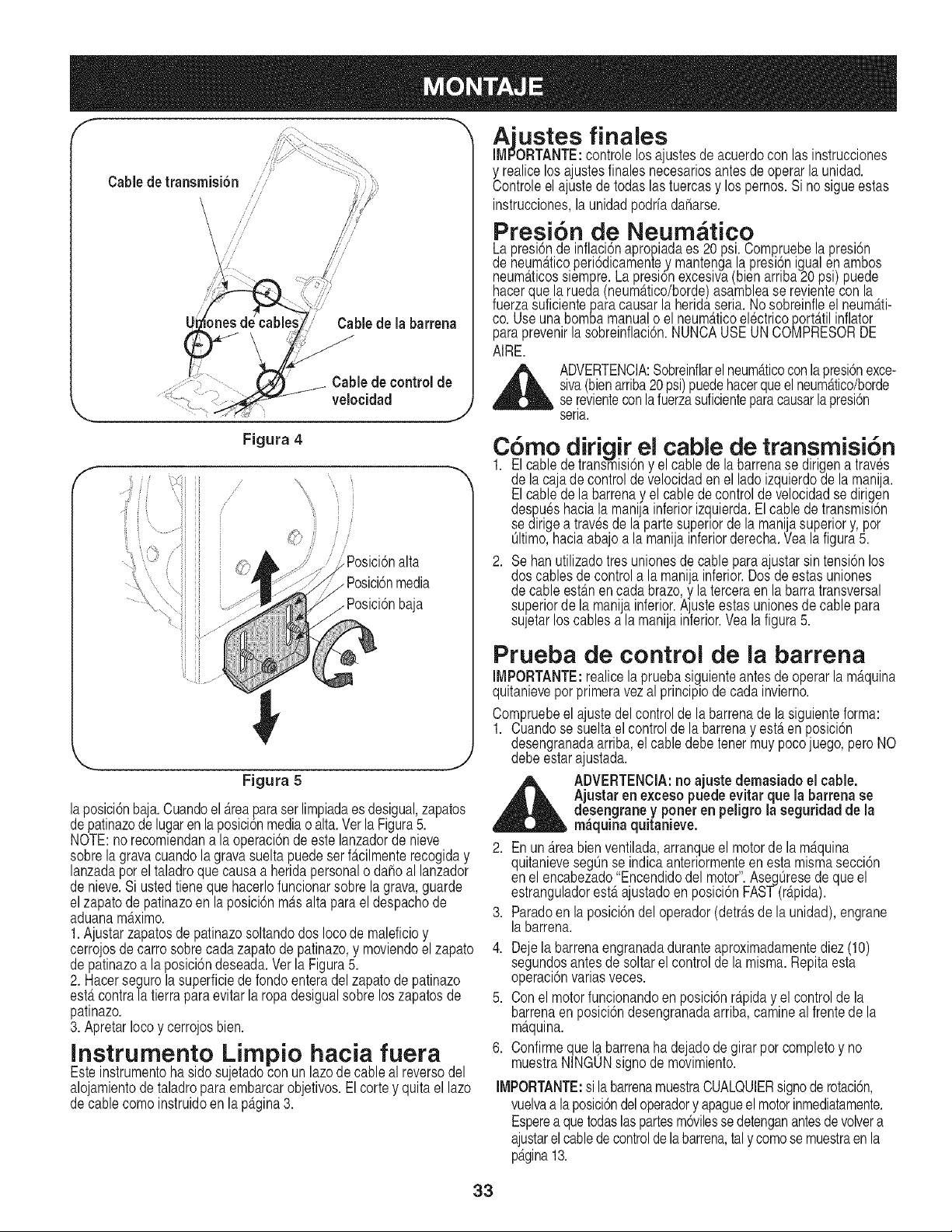
finales
==j v=vv
IMPORTANTE:controlelos ajustesde acuerdocon las instrucciones
Cable de transmisi6n
//
//
//
Cablede la barrena
Cable de controlde
velocidad
J
y realicelosajustesfinalesnecesariosantesdeoperarlaunidad.
Controleel ajustede todas las tuercasy los pernos.Si no sigueestas
instrucciones,la unidadpodriadaharse.
Presi6n de Neum tico
Lapresi6nde inflaci6napropiadaes 20 psi. Compruebelapresi6n
de neum_.ticoperi6dicamentey mantengalapresi6nigualenambos
neum_.ticossiempre.La presionexcesiva(bienarriba20 psi) puede
hacerquela rueda (neum_.tico/borde)asamblease revientecon la
fuerzasuficientepara causarla heridaseria.Nosobreinfleel neum_.ti-
co. Use unabombamanualo el neum_.ticoel@tricoport_.tilinflator
paraprevenirla sobreinflaci6n.NUNCAUSEUN COMPRESORDE
AIRE.
,_ ADVERTENCIA:Sobreinflarel neum_.ticoconla presi6nexce-
siva(bienarriba20psi)puedehacerqueelneum_ttico/borde
se[evienteconlafuerzasuficienteparacausarla presi6n
serla.
f--
Figura 4
,/
/
,/
ii f
Posici6nalta
. Posici6nmedia
baja
Figura 5
laposici6nbaja.Cuandoel Areaparaser limpiadaesdesigual,zapatos
depatinazode lugaren la posici6nmediaoalta.Verla Figura5.
NOTE:norecomiendana la operaci6nde estelanzadorde nieve
sobrelagravacuandolagravasueltapuedeserf_.cilmenterecogiday
lanzadaporel taladroque causaa heridapersonalo dahoal lanzador
de nieve.Si ustedtiene que hacerlofuncionarsobre lagrava,guarde
elzapatode patinazoen la posici6nm_tsalta para el despachode
aduanamaximo.
1.Ajustarzapatosdepatinazosoltandodos Iocode maleficioy
cerrojosde carrosobrecadazapatode patinazo,y moviendoel zapato
de patinazoa la posici6ndeseada.Verla Figura5.
2. Hacersegurolasuperficiede rondoenteradelzapatodepatinazo
est,.contrala tierrapara evitarla ropa desigualsobrelos zapatosde
patinazo.
3. ApretarIocoy cerrojosbien.
Instrumento Limpio hacia fuera
Esteinstrumentohasido sujetadocon un lazodecableal reversodel
alojamientode taladropara embarcarobjetivos.Elcortey quita el lazo
decablecomoinstruidoenla p_tgina3.
C6mo dirigir el cable de transmisi6n
1. El cablede transmisi6ny elcablede la barrenase dirigena traves
de la cajadecontroldevelocidaden el ladoizquierdode la manija.
Elcablede la barrenay el cabledecontroldevelocidadse dirigen
despueshaciala manijainferiorizquierda.Elcablede transmisl6n
se dirigea travesde laparte superiorde lamanijasuperiory,por
Oltimo,haciaabajo a la manijainferiorderecha.Yea la figura5.
2. Sehanutilizadotres unionesdecableparaajustarsin tensi6nlos
dos cablesde controla la manijainferior.Dosde estasuniones
de cableest_.nen cadabrazo,y la terceraen la barra transversal
superiorde la mania inferior.A usteestasunionesde cablepara
sujetar os cabes a a man a nferor.Yea a f gura 5.
Prueba de control de ia barrena
IMPORTANTE:realicela pruebasiguienteantesde operarla m_tquina
quitanievepor primeravezal principiode cadainvierno.
Compruebeel austedelcontrolde labarrenade la siguienteforma:
1. Cuandosesue ta e contro de a barrenay est,. en posc 6n
desengranadaarriba,el cabledebetenermuypocojuego,peroNO
debeestarajustada.
_ DVERTENClA:no ajuste demasiado el cable.
Ajustarenexcesopuedeevitarque la barrena se
desengraney poneren peligrola seguridad de la
m_quina quitanieve.
2. Enun_.reabienventilada,arranqueel motorde la m_.quina
quitanievesegOnse indicaanteriormenteen estamismasecci6n
en el encabezado"Encendidodel motor'.AsegOresede que el
estranguladorest,.ajustadoenposici6nFAST(r@ida).
3. Paradoen laposici6ndeloperador(detr_tsde launidad),engrane
labarrena.
4. Dee la barrenaengranadaduranteaproximadamentediez (10)
seguncbsantesdeso tar e contro de la misma.Repitaesta
operaclonvarlasveces.
5. Con el motorfuncionandoen posici6nr@iday el controlde la
barrenaen posici6ndesengranadaarriba,camineal frentede la
maquna.
6. Confirmeque labarrenahadejadode girarpor completoy no
muestraNINGUNsignode movimiento.
IMPORTANTE:si labarrenamuestraCUALQUIERsignoderotaci6n,
vuelvaa laposici6ndeloperadory apagueelmotorinmediatamente.
Esperea quetodaslaspartesm6vilessedetenganantesdevolvera
ajustarel cablede controlde la barrena,taly comose muestraenla
p_tgina13.
33
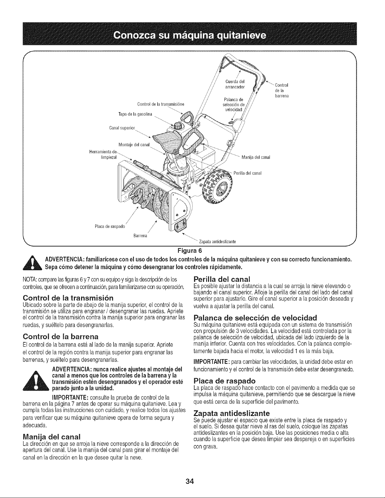
Control de la transmisi6ne
Tapa de la gasolina '---.
Canal superior
Montaje del canal
Herramienta de
limpiezal_
Manija del canal
de la
barrena
Perilla del canal
/
Placa de raspado
Barrena '_"--..
,_,., "_ Zapata antideslizante ,j
Figura 6
_ DVERTENClA:familiaricese con el uso de todos los controles de la m_quina quitanievey con su correcto funcionamiento.
Sepac6mo detenerla m_quinay c6modesengranarlos controlesr_pidamente.
NOTA:comparelasfiguras6y7consuequipoy sigaladescripci6ndelos
controles,queseofreoena continuaci6n,parafamiliarizarseconsuoperaci6n.
Control de la transmisi6n
Ubicadosobrelapartede abajode la manijasuperior,el controlde la
transmisi6nse utilizaparaengranar/ desengranarlas ruedas.Apriete
elcontroldela transmisi6ncontrala manijasuperiorparaengranarlas
ruedas,y suelteloparadesengranarlas.
Control de la barrena
Elcontrolde la barrenaest,. al lado de lamanijasuperior.Apriete
elcontroldela regi6ncontra la manijasuperiorpara engranarlas
barrenas,y sueltelopara desengranarlas.
ADVERTENCIA:nunca realice ajustes al montaje del
_ anal a menos que los controlesde la barrenay la
transmisi6n estendesengranadosy el operador este
paradojunto a la unidad.
IMPORTANTE:consultelapruebade controlde la
barrenaenlap_tgina7antesdeoperarsu m_.quinaquitanieve.Leay
cumplatodaslas instruccionescon cuidado,y realicetodoslos ajustes
paraverificarquesu m_tquinaquitanieveoperade formaseguray
adecuada.
Manija del canal
Ladirecci6nenquese arrojala nievecorrespondea la direcci6nde
aperturadelcanal.Usela manijadel canalparagirarel montajedel
canalenla direcci6nen la que deseequitarla neve.
PerilJa del canal
Esposibleajustarladistanciaa la cual se arrojala nieveelevandoo
bajandoel canalsuperior.Aflojela perilladelcanaldel ladodelcanal
superiorparaajustarlo.Gireel canalsuperiora la posici6ndeseaday
vuelvaa ajustar la perilladel canal.
Palanca de selecci6n de velocidad
Sum_.quinaquitanieveest,.equipadaconun sistemadetransmisi6n
con propulsi6nde3 velocidades.La velocidadest,.controladapor la
palancadeselecci6nde velocidad,ubicadadelladoizquierdodela
manijainferior.Cuentacon tres velocidades.Con la palancacomple-
tamentebajadahaciael motor,lavelocidad1es lam_tsbaja.
IMPORTANTE:paracambiarlasvelocidades,la unidaddebeestaren
funcionamientoy el controlde la transmisi6ndebeestardesengranado.
Placa de raspado
Laplacade raspadohacecontactocon el pavimentoa medidaque se
impulsala m_.quinaquitanieve,permitiendoquese descarguela nieve
queestercercade la superficiedel pavimento.
Zapata antideslizante
Sepuedeajustarel espacioqueexisteentre laplacade raspadoy
el suelo.Si deseaquitar nieveal ras delsuelo,coloquelas zapatas
antideslizantesen laposici6nbaja. Uselasposicionesmediaoalta
cuandolasuperficieque desealimpiarsea desparejao en superficies
con grava.
34
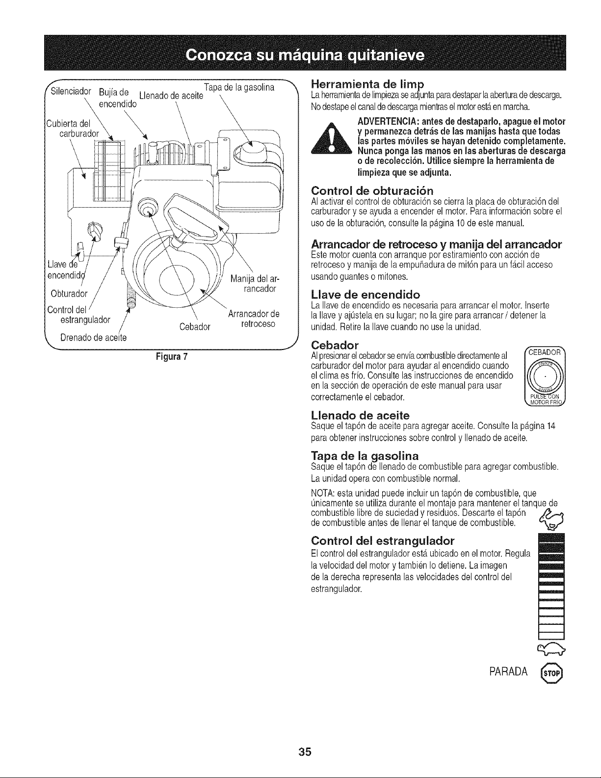
_Silenciador Bujiade LlenadodeaceiteTapa
de la
gasolina
encendido
Cubiertadel
carburador
Llave
Manijadel ar-
Obturador rancador
m
Controldel Arrancadorde
estrangulador Cebador retroceso
Drenadode aceite
,._ j
Figura7
Herramienta de limp
Laherramientadelimpiezaseadjuntaparadestaparla aberturade descarga.
Nodestapeelcanaldedescargamientraselmotorest,.enmarcha.
ADVERTENClA:antes de destaparlo, apague el motor
permanezcadetr_sde lasmanijas hastaque todas
Yaspartesm6viles se hayan detenidocompletamente.
Nunca pongalas manos en las aberturas de descarga
o de recolecci6n.Utilicesiempre la herramientade
limpiezaque se adjunta.
Control de obturaci6n
AI activarelcontrolde obturaci6nse cierrala placade obturaci6ndel
carburadory se ayudaa encenderel motor.Parainformaci6nsobreel
usode la obturaci6n,consultela p_tgina10de este manual.
Arrancador de retroceso y manija del arrancador
Estemotorcuentacon arranquepor estiramientocon acci6nde
retrocesoy manijade la empuhadurade mit6nparaunf_tcilacceso
usandoguanteso mitones.
Llave de encendido
LaIlavedeencendidoes necesariapara arrancarel motor.Inserte
laIlavey ajOstelaen su lugar;no la gireparaarrancar/ detenerla
unidad.Retirela Ilavecuandono usela unidad.
Cebador
AIpresionarel oebadorseenvfacombustibledirectamenteal / u_-_A._uuH}
carburadordelmotorparaayudaral encendidocuando
el clima esfrio. Consultelas instruccionesde encendido
en la secci6nde operaci6nde estemanualparausar
correctamenteelcebador.
Llenado de aceite
Saqueeltap6nde aceiteparaagregaraceite.Consultela p_tgina14
paraobtenerinstrucoionessobrecontroly Ilenadode aceite.
Tapa de la gasolina
Saqueeltap6nde Ilenadodecombustibleparaagregarcombustible.
Launidadoperaconcombustiblenormal.
NOTA:esta unidadpuedeincluiruntap6nde combustible,que
Onicamentese utiliza duranteel montajepara mantenerel tanquede
combustiblelibre de suciedady residuos.Descarteel tap6n ,_f_f.e
de combustibleantes de Ilenarel tanquede combustible.
Control del estrangulador
Elcontroldelestranguladorest,. ubicadoenel motor.Regula
lavelocidaddel motory tambienIo detiene.Laimagen
de la derecharepresentalasvelocidadesdelcontroldel
estrangulador.
q;::>
PARADA 0
35
Antes de encender el motor
Aceite del motor
Elmotorseenviaconaceiteenelmotor.Compruebeel nivelde aceite
antesdelprimeruso.ParalosIlenadossubsiguientes,useel gradode
aceiteparamotorespecificadoen la p_tgina14.Paraagregaraceitel:
1. Saquela varilladel niveldeaceitedelorificiode Ilenadode aceite.
Viertaaceitenuevolentamentea travesdel tap6n.Reemplacela
varilladelnivelde aceite.
2. Controley compruebequeel nivelde aceiteeste hasta arribaen la
marcaFULLde la varilladel niveldelaceite.
Gasolina
ADVERTENCIA:la gasolinaesinflamable;tenga
_ precauci6ncuandola manipule o la almacene. No
Ilene eltanque de combustiblemientras la m_quina
quitanieve est_ien marcha,cuandoest_ calienteo
cuandoest_en un _rea cerrada.
_ DVERTENCIA:eviteque sum_quina quitanieve
entreencontactoconllamasabiertas o chispas
el_ctricasy no fume mientras seagrega combustible.
1. NuncaIleneel tanquedecombustiblecompletamente.Lleneel
tanquenom_.sde 1/2pulgadapor debajode la basedelcuellodel
Ilenadorparadejarespacioparaladilataci6ndelcombustible.
NOTA:estaunidadpuedeincluirun tap6ndecombustible,que
Onicamentese utilizaduranteelmontajeparamantenerel tanque
decombustiblelibre de suciedady residuos.Descarteel tap6nde
combustibleantesde Ilenarel tanquede combustible.
2. Siempreuse gasolinaparaautomotoressin plomo, limpiay nueva.
Lleneel tanquede combustiblealaire librey use un embudoo pico
paraevitarderrames.AsegOresede que el recipientedesdeel cual
viertelagasolinaeste limpioy no este oxidadoni contaminadocon
otrasparticulasextrahas.AsegOresede limpiarel combustibleque
se hayaderramadoantesde arrancarel motor.
3. AIfinalizarel trabajo,vacieel tanquedecombustiblesi la m_.quina
quitanieveno ser_tutilizadadurantelos siguientes30 dias o m_.s.
Almacenela gasolinaen un recipientelimpioy mantengala tapa
bienubicadaen el recipiente.
PRECAUClON:nunca use productos de limpieza para el motor o
el carburadoren el tanque decombustible.
Para encender el motor
ADVERTENClA:aseg_resede que ninguna persona
,_ adem_s del operador este parada cerca de la m&qui-
na quitanieve mientras arranca u opera. No opere
esta m_quina quitanieve a menos que el montaje
del canal hayasido correctamente instaladoy est_
asegurado.
NOTA:paraubicartodoslos controlesdelmotorquese mencionanen
estasecci6n,consultela figura7.
Encendido en frio
1. Aseg0resedequelos controlesdela barrenay la transmisi6n
est_mdesengranados.Conecteel cablede labujiaa la misma.
2. Enciendala v_tlvula,si es partedel equipo.
3. Muevael controldel estranguladora laposici6nFAST(r_tpido).
4. Presionela tecla en laranurade encendidohastaqueencajea
presi6nensu lugar.No girela Ilave.
5. Roteel controlde obturaci6na posici6nFULLdelobturador.
6. Presioneel bot6ndelcebadormientrascubreel agujerode
ventilaci6n.Quitesu dedo del cebadorentre un cebadoy otro.No
cebe si la temperaturasuperalos 50°F;cebedos vecesentre50°F
y 15°F;y cebe cuatrovecespordebajode 15°R
7. Tomela manijadel arrancadory saquecuerdalentamentehasta
queel motoralcanceel comienzodel ciclode compresi6n(la
cuerdatirar_,unpoco masfuerteen este punto).Dejequela
cuerdase enrosquelentamente.
8. Tire de la cuerdademanerar_.piday continua.Mantengafirme la
manijadelarrancador,dejeque lacuerdaregreselentamenteal
arrancador.Repitahastaque el motorse encienda.
9. Mientrasse calientael motor,rote lentamentelaperilladel
obturadora posici6nOFF (apagado).Si el motorfalla,gire hacia
posici6nFULL,luegomuevalentamentehaciaposici6nOFF.
10.Dejequeel motorse enfrieporalgunosminutosyaqueel motorno
alcanzar_,lapotenciatotalhastaIograrlatemperaturaoperativa.
11.Opereel motorcon el estranguladoral m_tximo(R.4PIDO)cuando
estearrojandonieve.
Encendido en caliente:
1. si vuelvea arrancarun motordespuesde una paradatemporal,
rote el obturadora posici6nOFFen lugarde FULLy no Iocebe.
Tire dela manijadel arrancadorcomo se explic6anteriormente.
Antes de detener la m quina
1. Dejeencendidoel motordurantealgunosminutosparapermitirque
se sequela humedaden elmismo.
2. Paraevitarunposiblecongelamiento,sigaestospasos:
Arrancador de retroceso
a. Con el motoren funcionamiento,tirecon fuerzade la sogadel
arrancadortreso cuatrovecesde maneracontinuay seguida.
Procedimiento para detener ia
m iquina quitanieve
1. Para detenerlas ruedas,suelteel controlde latransmisidn.
2. Para dejar de quitarla nieve,suelteelcontrolde labarren&
3. Paradetenerel motorpresionelapalancadecontroldelestrangulador
hastalaposici6nOFF(apagado)y saquelaIlave.NogirelaIlave.
ADVERTENClA:la temperatura del silenciador y de las
_reas que Io rodean puedesuperar los 150° F.Evite
dichas _reas.
Procedimiento para quitar la nieve
PRECAUClON:reviselazonaquedesealimpiarparadetectarla
presenciade objetosextrahos.Refirelossi los hay.
1. Enciendael motorsiguiendolas instruccionesdeencendido.
2. Dejequeel motorsecalienteunosminutosyaqueelmismono desarrolla
lapotenciam_tximahastaquealcanzalatemperaturadefuncionamiento.
3. Gire el montajedelcanalhaciala direcci6ndeseada,lejosde
transeOnteso edificios.
4. AsegOresede que nohayaningOntranseOnteni ningOnobjeto
enfrentede la unidad,presioneel controlde labarrenacompleta-
mentehastaengranartotalmentelas barrenas.
5. Mientrasengranael controlde labarrena,presioneel control
de la transmisi6ncompletamentecontra la manijasuperiorpara
engranarlas ruedas.No"expanda"el controlde transmisi6n.
36
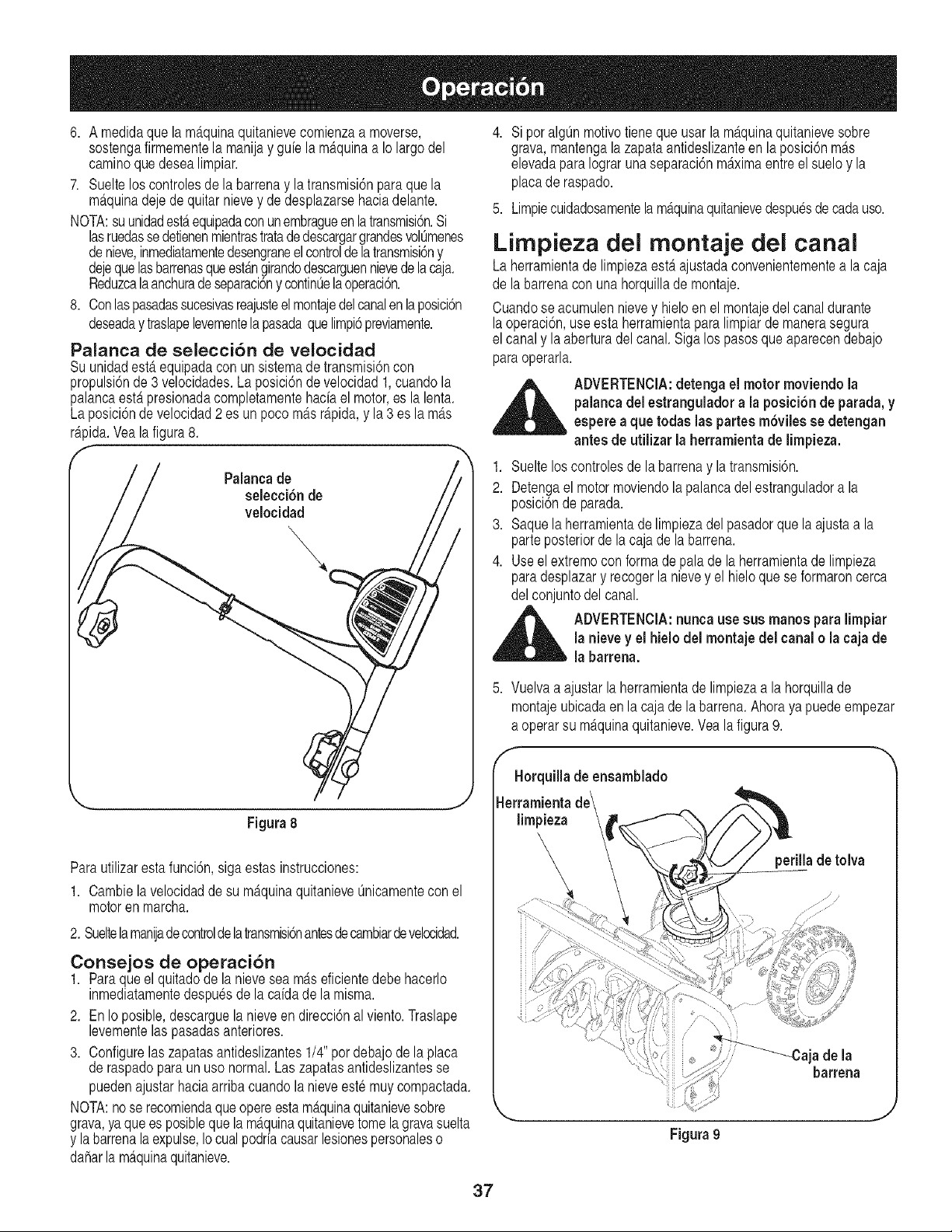
6. A medidaquela mAquinaquitanievecomienzaa moverse,
sostengafirmementela manijay guiela mAquinaa Iolargo del
caminoquedesealimpiar.
7. Suelteloscontrolesde la barrenay la transmisi6npara que la
mAquinadejedequitar nievey de desplazarsehaciadelante.
NOTA:suunidadestAequipadaconunembragueenlatransmisi6n.Si
lasruedassedetienenmientrastratadedescargargrandesvolOmenes
denieve,inmediatamentedesengraneel controlde latransmisi6ny
dejequelasbarrenasqueestAngirandodescarguennievede la caja.
Reduzcalaanchuradeseparaci6ny continuelaoperaci6n.
8. Conlaspasadassucesivasreajusteelmontajedelcanalenlaposici6n
deseaday traslapelevementela pasadaque limpi6previamente.
Palanca de selecci6n de velocidad
SuunidadestAequipadaconun sistemade transmisi6ncon
propulsi6nde 3 velocidades.La posici6nde velocidad1,cuandola
palancaestapresionadacompletamentehaciael motor,es lalenta.
Laposici6nde velocidad2 es un poco mAsrApida,y la 3 es lamAs
rApida.Veala figura8.
f
Palancade
selecci6n de
velocidad
4. SiporalgOnmotivotieneque usarla maquinaquitanievesobre
grava,mantengala zapataantideslizanteen la posici6nmAs
elevadaparaIograrunaseparaci6nmaximaentreelsuelo y la
placade raspado.
5. Limpiecuidadosamentelamaquinaquitanievedespuesde cadauso.
Lirnpieza del rnontaje del canal
Laherramientade limpiezaestaajustadaconvenientementea la caja
de la barrenacon una horquillade montaje.
Cuandose acumulennievey hieloen el montajedel canaldurante
laoperaci6n,useesta herramientaparalimpiarde manerasegura
el canaly la aberturadel canal. Sigalos pasosque aparecendebajo
paraoperarla.
_ DVERTENCIA:detenga el motor moviendo la
palancadelestranguladora la posici6nde parada,y
esperea que todas las partes m6viles se detengan
antesde utilizar la herramientade limpieza.
1. Sueltelos controlesde labarrenay latransmisi6n.
2. Detengael motormoviendola palancadel estranguladora la
posici6nde parada.
3. Saquelaherramientade limpiezadel pasadorque la ajustaa la
parteposteriorde lacaja de la barrena.
4. Useel extremocon formade paladela herramientade limpieza
paradesplazary recogerla nievey el hieloquese formaroncerca
del conjuntodel canal.
ADVERTENClA:nunca use sus manos para limpiar
la nieve y el hielodel montaje del canalo la cajade
la barrena.
5. Vuelvaa ajustarlaherramientade limpiezaa la horquillade
montajeubicadaen la cajade la barrena.Ahora yapuede empezar
a operarsu mAquinaquitanieve.Vea la figura9.
Figura8
Parautilizarestafunci6n,sigaestas instrucciones:
1. Cambiela velocidadde su maquinaquitanieveOnicamenteconel
motoren marcha.
2. Sueltelamaniadecontrolde latransmisi6nantesdecambiardevelcoidad.
Consejos de operaci6n
1. Paraque el quitadodela nieveseamaseficientedebehacerlo
inmediatamentedespuesdela caidade la misma.
2. En Io posible,descarguelanieveen direcci6nal viento.Traslape
levementelas pasadasanteriores.
3. Configurelas zapatasantideslizantes1/4" pordebajode la placa
de raspadopara un uso normal.Las zapatasantideslizantesse
puedenajustarhaciaarribacuandola nieveestemuycompactada.
NOTA:nose recomiendaqueopereestamaquinaquitanievesobre
grava,ya quees posibleque la maquinaquitanievetomela gravasuelta
y labarrenalaexpulse,Iocualpodriacausarlesionespersonaleso
daharlamaquinaquitanieve.
Figura9
37
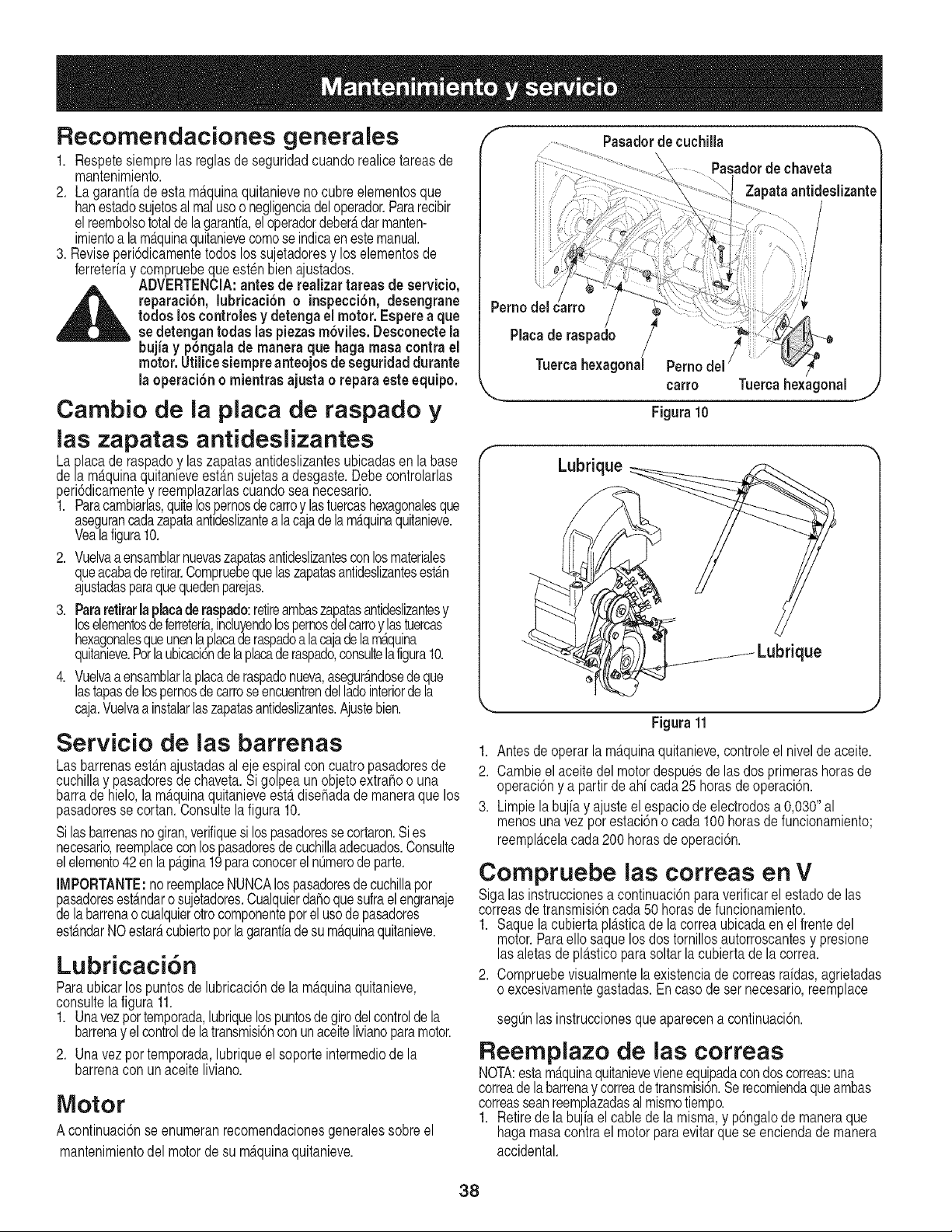
Recomendaciones generales
1. Respetesiemprelasreglasde seguridadcuandorealicetareasde
mantenimiento.
2. La garanfiade esta m_.quinaquitanievenocubreelementosque
hanestadosujetosal realusoo negligenciadeloperador.Pararecibir
elreembolsototaldelagarantfa,eloperadordeber_tdarmanten-
imientoa la m_.quinaquitanievecomose indicaenestemanual.
3. Reviseperi6dicamentetodos los sujetadoresy los elementosde
ferreteriay compruebeque esten bien ajustados.
_ ADVERTENClA:antes de realizar tareas de servicio,
reparaci6n, lubricaci6n o inspecci6n, desengrane
todos loscontrolesy detengael motor. Esperea que
sedetengantodas laspiezasm6viles. Desconectela
bujiay pbngalade manera que haga masa contrael
motor. Utilicesiempreanteojos de seguridad durante
la operaci6n o mientras ajusta o reparaesteequipo.
Cambio de ia placa de raspado y
ias zapatas antideslizantes
Laplacade raspadoy laszapatasantideslizantesubicadasen labase
dela m_.quinaquitanieveest_.nsu etas a desgaste.Debecontrolarlas
peri6dicamentey reemplazarlascuandosea necesario.
1. Paracambiarlas,quitelospernosdecarroy lastuercashexagonalesque
asegurancadazapataantldeslizantealacajadelam_tquinaquitanieve.
Veala figura10.
2. Vuelvaa ensamblarnuevaszapatasantideslizantesconlosmateriales
queacabaderetirar.Compruebequelaszapatasantideslizantesest_tn
ajustadasparaquequedenparejas.
3. Pararetirarlaplacade raspado:retireambaszapatasantideslizantesy
loselementosde ferreteria,incluyendolospernosdelcarroylastuercas
hexagonalesqueunenlaplacade raspadoa lacaa dela m_.quina
quitanieve.Porlaubicaci6nde laplacaderaspado,consultelafigura10.
4. Vuelvaa ensamblarlaplacaderaspadonueva,asegur_tndosedeque
lastapasde lospernosde carroseencuentrendel ladointeriordela
caja.Vuelvaa instalarlaszapatasantideslizantes.Ajustebien.
Servicio de ias barrenas
Lasbarrenasest_.najustadasaleje espiralcon cuatropasadoresde
cuchillay pasadoresde chaveta.Si golpea un objetoextrafioo una
barrade hielo,la m_.quinaquitanieveesterdisefladade maneraque los
pasadoresse cortan.Consultela figura 10.
Silasbarrenasno giran,verifiquesi lospasadoresse cortaron.Si es
necesario,reemplaoeconlospasadoresdecuchillaadecuados.Consulte
elelemento42enlap_.gina19paraconocerel nOmerodeparte.
IMPORTANTE:noreemplaceNUNCAlospasadoresdecuchillapor
pasadoresest_.ndaro sujetadores.Cualquierdafloquesufrael engranaje
delabarrenaocualquierotrocomponenteporel usode pasadores
est_mdarNOestar_tcubiertoporla garantiade sum_tquinaquitanieve.
Lubricaci6n
Paraubicarlos puntosde lubricaci6nde la m_tquinaquitanieve,
consultela figura11.
1. Unavezpor temporada,lubriquelospuntosde giro delcontroldela
barrenay elcontrolde latransmisi6nconunaceitelivianoparamotor.
2. Unavez por temporada,lubriqueel soporteintermediode la
barrenacon unaceite liviano.
Motor
A continuaci6nseenumeranrecomendacionesgeneralessobreel
mantenimientodel motorde su m_tquinaquitanieve.
f
Pasadorde cuchilla
Pasadorde chaveta
Zapataantideslizante
Pernodelcarro
Piacaderaspado / /
Tuercahexagonal Pernodel
carro Tuercahexagonal _.Y
Figura10
Lubrique
;_ue
°i
J
Figura11
1. Antes de operar la maquinaquitanieve,controleel nivelde aceite.
2. Cambieel aceitedel motordespuesde las dosprimerashorasde
operaci6ny a partir de ahi cada25 horasde operaci6n.
3. Limpiela buiay a usteel espaciodeelectrodosa 0,030"al
menosunavezporestaci6nocada 100horasdefuncionamiento;
reemplacelacada200 horasde operaci6n.
Compruebe ias correas en
V
Sigalas instruccionesa continuaci6nparaverificarel estadode las
correasde transmisi6ncada 50 horasde funcionamiento.
1. Saque la cubiertapl_.sticade lacorreaubicadaen elfrentedel
motor.Paraellosaquelos dostornillosautorroscantesy presione
las aletasdepl_.sticoparasoltarlacubiertadela correa.
2. Compruebevisualmentela existenciadecorreasraidas,agrietadas
o excesivamentegastadas.En casode ser necesario,reemplace
seg_3nlas instruccionesque aparecena continuaci6n.
Reemplazo de ias correas
NOTA:estamaquinaquitanievevieneequipadacondoscorreas:una
correadelabarrenay correadetransmisi6n.Se recomiendaqueambas
correasseanreemplazadasal mismotiempo.
1. Retirede la bujia el cable de la misma,y p6ngalode maneraque
hagamasacontrael motorparaevitar quese enciendade manera
accidental.
38
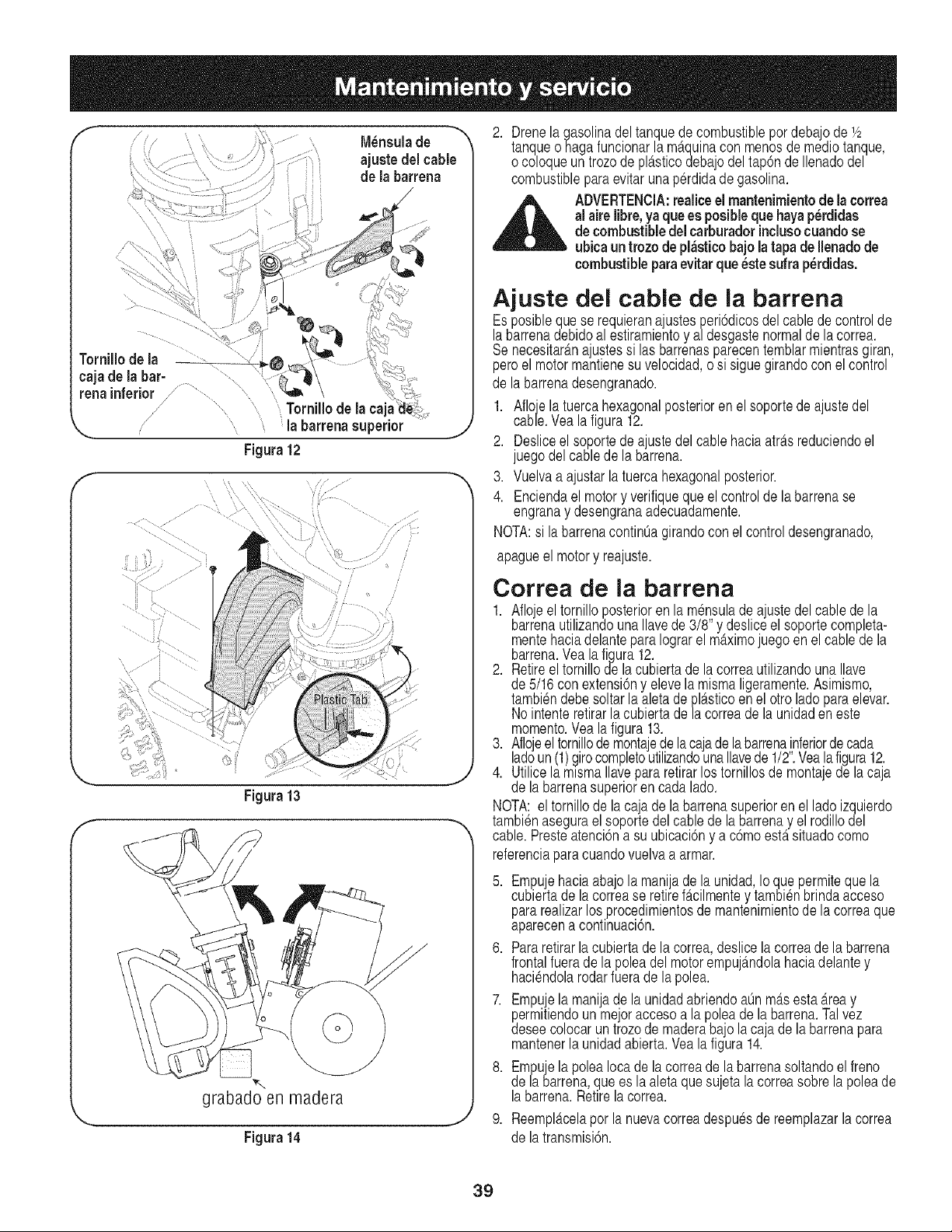
f
M_nsulade "'_
ajuste delcable
de la barrena
...........
renainferior / ............................ _"_" \
// ...... Tornillode la ca
"-.. la barrenasuperior
Figura12
f
,J
f
//' /
/
/
f
Figura 13
J
%,_,,
grabadoen madera
Figura14
2. Drenela gasolinadel tanquedecombustiblepordebajode V2
tanqueohaga funcionarla m_.quinacon menosde medic tanque,
o coloqueun trozode pl_tsticodebajodel tap6nde Ilenadodel
combustiblepara evitar unaperdidade gasolina.
_ DVERTENClA:realiceel mantenimientode lacorrea
al aire libre,yaque es posibleque hayap_rdidas
de combustibledel carburadorinclusocuandose
ubicaun trozo de pl&sticobajo latapa deIlenadode
combustibleparaevitarque_stesufra perdidas.
Ajuste del cable de ia barrena
Esposiblequese requierana ustesperi6dicosdel cablede controlde
labarrenadebidoal estiramientoy a/desgastenormalde la correa.
Senecesitar_.na ustessi lasbarrenasparecentemblarmientrasgiran,
peroe motormantenesu ve oc dad,o s s guegirandocon elcontrol
de la barrenadesengranado.
1. Afloe la tuercahexagonalposterioren el soportedeajustedel
cabe. Vea a fgura 12.
2. Desliceel soportede austedelcable haciaatr_tsreduciendoel
juegodel cablede la barrena.
3. Vuelvaa ajustarla tuercahexagonalposterior.
4. Enciendael motory verifiqueque el controlde la barrenase
engranay desengranaadecuadamente.
NOTA:si la barrenacontinOagirandoconel controldesengranado,
apagueel motory reajuste.
Correa de la barrena
1. Afloe el tornilloposterioren la m_nsuladea ustedel cablede la
barrenautilizandounaIlavede 3/8" y desliceel soportecompleta-
mentehaciadelanteparaIograrel dtximo juego en el cablede la
barrena.Yealafigura 12.
2. Retireeltornillode la cubiertade la correautilizandouna Ilave
de 5/16con extensi6ny elevela mismaligeramente.Asimismo,
tambi_ndebesoltarlaaletade pl_.sticoen el otroladoparaelevar.
Nointenteretirarlacubiertadela correade la unidadeneste
momento.Vealafigura 13.
3. Aflojeel tornillode montajede la cajade la barrena,inferiorde cada
ladoun (1)girocompletoutilizandounaIlavede 1/2. Yealafigura12.
4. Utilicela mlsmaIlavepara retirarlos tornillosde montajede la caja
de la barrenasuperioren cadalado.
NOTA:el tornillode lacaja dela barrenasuperioren el ladoizquierdo
tambienasegurael soportedel cable de la barrenay el rodillodel
cable.Presteatenci6na su ubicaci6ny a c6moestersituadocomo
referenciaparacuandovuelvaa armar.
5. Empujehaciaabajola manijade la unidad,Io quepermitequela
cubiertade la correase retirefMImente y tambienbrindaacceso
pararealizarlos procedimientosdemantenimientode la correaque
aparecena continuaci6n.
6. Pararetirarlacubiertade la correa,deslicelacorreade la barrena
frontalfuerade la poleadel motorempuj_mdolahaciadelantey
haciendolarodarfuerade la polea.
7. Empue la mania de launidadabriendoaOnm_.sesta_.reay
permitiendoun mejoraccesoa la poleade la barrena.Talvez
deseecolocaruntrozode maderabajolacaja de la barrenapara
mantenerla unidadabierta.Yea la figura14.
8. EmpujelapoleaIocade la correade la barrenasoltandoel freno
de la barrena,que es laaleta quesu eta la correasobrela poleade
labarrena.Retirelacorrea.
j 9. Reempl_tcelaporla nuevacorreadespuesdereemplazarla correa
de la transmisi6n.
39
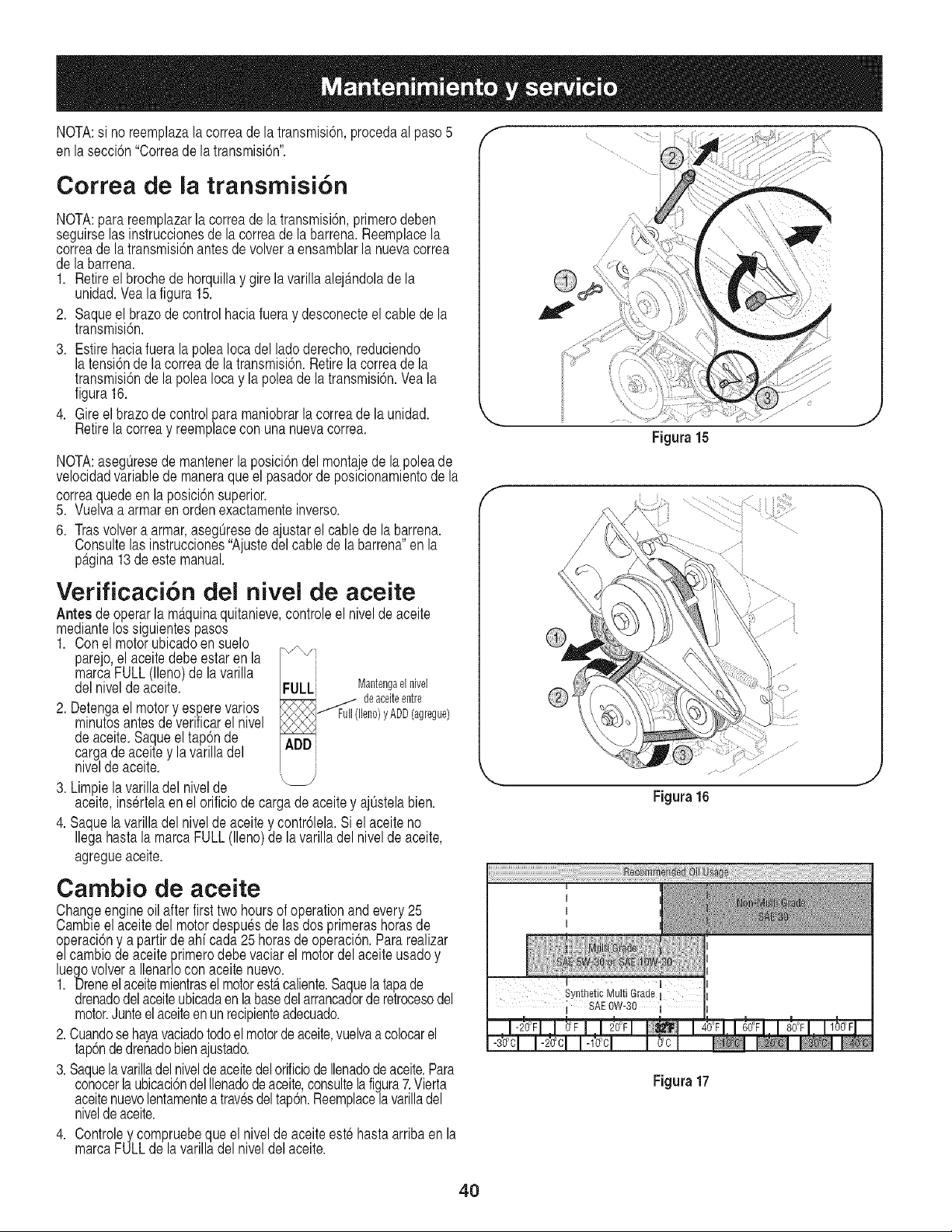
NOTA:si no reemplazalacorreadela transmisi6n,procedaal paso5
en la secci6n"Correade latransmisi6n'.
Correa de ia transmisi6n
NOTA:parareemplazarla correade la transmisi6n,primerodeben
seguirselasinstruccionesde la correade la barrena.Reemplacela
correade la transmisi6nantesdevolvera ensamblarla nuevacorrea
de la barrena.
1. Retireel brochede horquillay girelavarillaalej_mdolade la
unidad.Vealafigura 15.
2. Saqueel brazode controlhaciafueray desconecteel cablede la
transmisi6n.
3. Estire haciafuera la polea Iocadel ladoderecho,reduciendo
la tensi6nde la correade la transmisi6n.Retirelacorreade la
transmisi6nde la poleaIocay la poleade la transmisi6n.Veala
figura16.
4. Gire el brazode controlparamaniobrarla correade la unidad.
Retirela correay reemplacecon unanuevacorrea.
NOTA:asegOresede mantenerla posici6ndel montae dela poleade
velocidadvariablede maneraqueel pasadorde posicionamientode la
correaquedeen la posici6nsuperior.
5. Vuelvaa armaren ordenexactamenteinverso.
6. Trasvolvera armar,asegOresede a ustarel cablede labarrena.
Consultelas instrucciones"Ajustedelcablede la barrena'en la
p_tgina13deeste manual.
Verificaci6n del nivel de aceite
Antesde operarla m_.quinaquitanieve,controleel nivelde aceite
mediantelos siguientespasos
1. Conel motorubicadoensuelo
parejo,el aceitedebe estar enla
marcaFULL(lleno)de la varilla
delnivelde aceite. FULLi Mantengaelnivel
R2qR;R_ deaceiteentre
2. Detengael motory esperevarios _,/_J Full(lleno)yADD(agregue)
minutosantesde verificarel nivel
deaceite.Saqueeltap6n de ADD
cargadeaceitey la varilladel
niveldeaceite.
3. Limpielavarilladel nivelde
aceite,insertelaen el orificiode cargade aceitey ajOstelabien.
4. Saquela varilladel nivelde aceitey contr61ela.Siel aceite no
IlegahastalamarcaFULL(lleno)de la varilladel nivelde aceite,
agregueaceite.
f
f
e
Figura15
Cambio de aceite
Changeengineoil after firsttwo hoursof operationand every 25
Cambieelaceitedel motordespuesde lasdos primerashorasde
operaci6ny a partirde ahi cada25 horasdeoperaci6n.Para realizar
e/cambio deaceiteprimerodebevaciarel motordel aceiteusadoy
luegovolvera Ilenarlocon aceitenuevo.
1. Dreneel aceitemientrasel motorestercaliente.Saquela tapade
drenadodelaceiteubicadaen la basedel arrancadorde retrocesodel
motor.Junteel aceiteenunrecipienteadecuado.
2.Cuandose hayavaciadotodoel motordeaceite,vuelvaa colocarel
tap6ndedrenadobienajustado.
3. SaquelavarilladelniveldeaceitedelorificiodeIlenadodeaceite.Para
conocerlaubicaci6ndelIlenadodeaoeite,consultelafigura7.Vierta
aceitenuevolentamentea travesdeltap6n.Reemplacelavarilladel
niveldeaceite.
4. Controley compruebeque elnivelde aceiteestehastaarribaen la
marcaFULLde la varilladel niveldelaceite.
Synthetic Multi Grade
; SAEOW-30
1
I
Figura17
4O
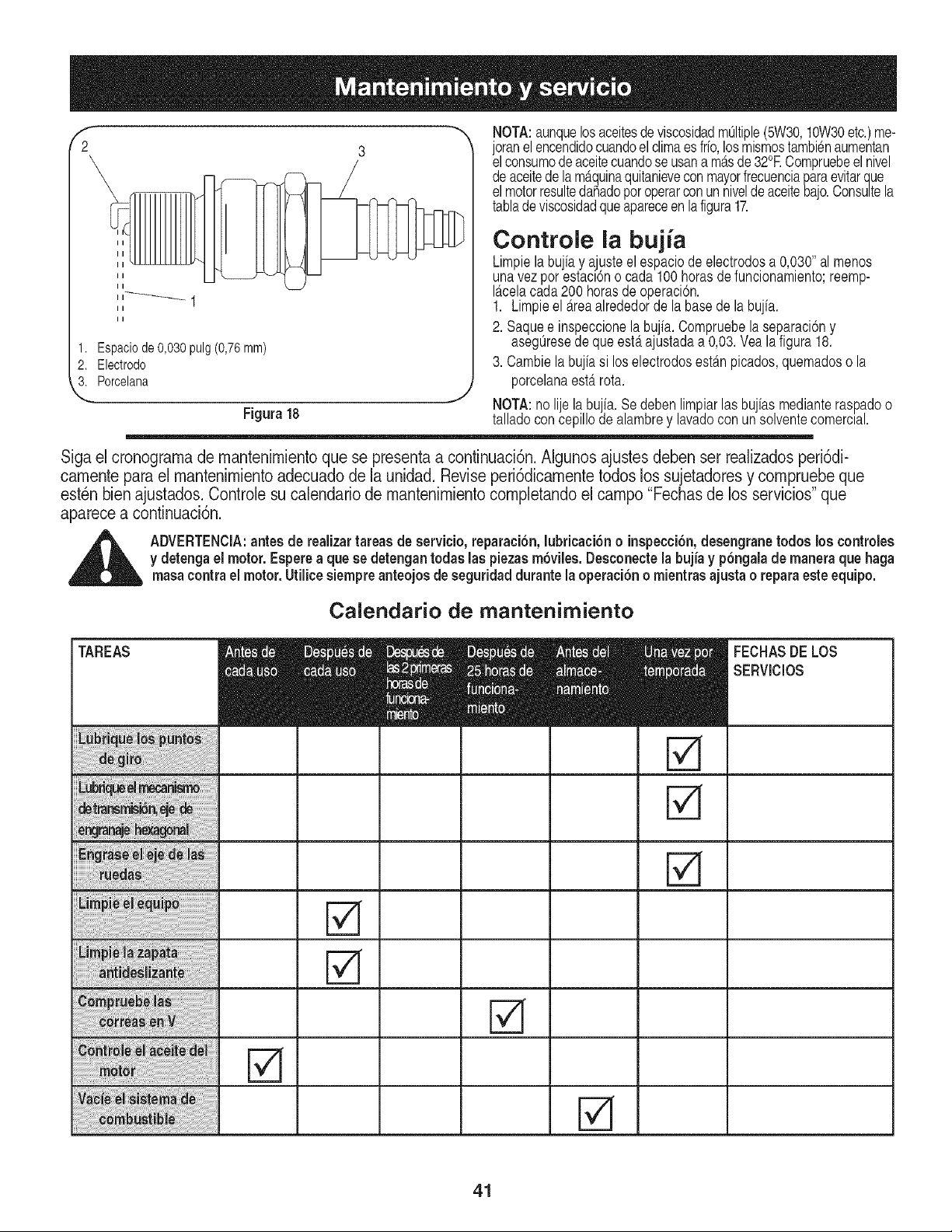
II
II
II
f
2
1. Espaciode0,030pulg(0,76ram)
2. Electrodo
3. Porcelana
Figura18
NOTA:aunquelosaceitesde viscosidadmOltiple(5W30,10W30etc.)me-
oranelencendidocuandoel climaes frio,losmismostambienaumentan
e consumodeacetecuandoseusana m_.sde32°RCompruebee nve
deaceitede la m_tquinaquitanieveconmayorfrecuenciaparaevitarque
el motorresultedahadoporoperarconun nivelde aceitebajo.Consultela
tabladeviscosidadqueapareceenlafigura17.
Controle la bujia
Limpiela bujia y ajusteel espaciodeelectrodosa 0,030"al menos
unavezpor estacl6no cada100 horasde funcionamientcreemp-
I_.celacada200 horasde operaci6n.
1. Limpieel _.reaalrededorde la basede la bujia.
2. Saquee inspeccionela bujia. Compruebelaseparaciony
asegOresede que est,. ajustadaa 0,03. Yeala figura18.
3. Cambielabujiasi los electrodosest_mpicados,quemadoso la
porcelanaesterrota.
J NOTA:no lie labu ia. Se debenlimpiarlas buias medianteraspadoo
talladocon cep o deaambrey avadocon un so ventecomercla.
Siga el cronograrna de mantenimiento que se presenta a continuaci6n. AIgunos ajustes deben set realizados peri6di-
carnente para el mantenimiento adecuado de la unidad. Revise peri6dicamente todos los sujetadores y compruebe que
esten bien ajustados. Controle su calendario de mantenimiento completando el carnpo "Fechas de los servicios" que
aparece a continuaci6n.
,_ ADVERTENClA:antes de realizartareas de servicio,reparaci6n, lubricaci6n o inspecci6n,desengranetodos los centroles
y detengael motor. Espere a quese detengantodas las piezasm6viles.Desconectela bujia y p6ngalade maneraque haga
masacontrael motor. Utilicesiempre anteojosde seguridad durantela operaci6n o mientras ajustao reparaesteequipo.
Calendario de mantenimiento
TAREAS FECHASDELOS
SERVIClOS
41
Sinosevaa utilizaelequipodurante30 diaso m_.s,o si eselfinaldela
temporadadenievey ya noexisteposibilidaddequenieve,es necesario
almacenarelequipode maneraadecuada.Sigalas instrucciones
dealmacenamientoquese indicana continuaci6nparagarantizarel
rendimientom_tximodelam_tquinaquitanievedurantemuchosahos.
Preparaci6n del motor
ADVERTENCIA: nunca almacene la
m_quina quitanieve con combustible en el
tanque en un espacio cerrado o en _reas
con poca ventilaci6n, donde los gases
del combustible puedan alcanzar el fuego, chispas
o una luz piloto como la que tienen algunos hornos,
calentadores de agua, secadores de ropa o alg_n otto
dispositivo a gas.
NOTA:Es importanteevitarqueduranteelalmacenamientose
formendep6sitosde gomaen laspiezasesencialesdel sistemade
combustibledel motorcomo,por ejemplo,en el carburador,elfiltrode
combustible,la manguerade combustibleo el dep6sito.
PRECAUClON:Aloscombustiblescon mezclade alcohol(quese
Ilamangasohol,o queutilizanetanolo metanol)puedenatraerla
humedad,Io queconducea la separaci6ny formaci6nde_.cidos
duranteel almacenamiento.El gas addico puededaharel sistemadel
combustiblede un motorduranteel almacenamientodel mismo.
Paraevitarproblemascon el motor,elsistemadel combustibledebe
ser vaciadoantesdealmacenarlam_tquinadurante30 dias o m_ts.
Sigaestas instruccionesparaprepararsu m_tquinaquitanievepara
almacenarla:
ADVERTENCIA: drene el combustible
dentro de un recipiente aprobado en
un lugar exterior, lejos de todo tipo de
fuego. Compruebe que el motor est_ fdo.
No fume. El combustible que se deje en el motor se
deteriora cuando el clima es c;_lido y causa graves
problemas de encendido.
1. Pongaelmotorenmarchahastavaciarel dep6sitodecombustible
y hastaqueelmotorse detengadebidoa lafaltadecombustible.
NOTA:El usode estabilizadoresdecombustible(como STA-BIL)es
unaalternativaaceptablepara minimizarla formaci6nde dep6sitosde
gomade combustibleduranteel almacenamiento.Agregueel estabili-
zadora la gasolinaquese encuentraen el dep6sitode combustibleo
en el recipientede almacenamiento.Respetesiemprela proporci6nde
mezcladoquefiguraenel recipientedelestabilizador.Pongael motor
en marchapor Io menos10 minutosdespuesde agregarel estabiliza-
dorparapermitirleIlegaral carburador.Nodreneel carburadorsi ester
utilizandoun estabilizadorde combustible.
2. Retire la bujia y vierta (1)onza de aceite paramotora travesdel
orificiodela bujia y haciael interiordel cilindro.Cubrael orificiode
la bujia con un trapoy pongael motoren marchavariasveces para
distribuirel aceite.Reemplacela bujia.
Preparaci6n de ia m quina quitanieve
1. Cuandoalmacenela m_.quinaquitanieveen ungalp6nde dep6sito
met_.licoocon pocaventilaci6n,tengaespecialcuidadode
realizarleuntratamientoanti- oxidanteal equipo.Use aceite ligero
o silic6npara recubrirelequipo,especialmentelascadenas,los
resortes,los cojinetesy los cables.
2. Eliminetodoel polvodelexteriordel motory delequipo.
3. Siga las recomendacionesde lubricaci6nen la secci6nde
mantenimientodeestemanual.
4. Almaceneel equipoen unAreadespejaday seca.
42
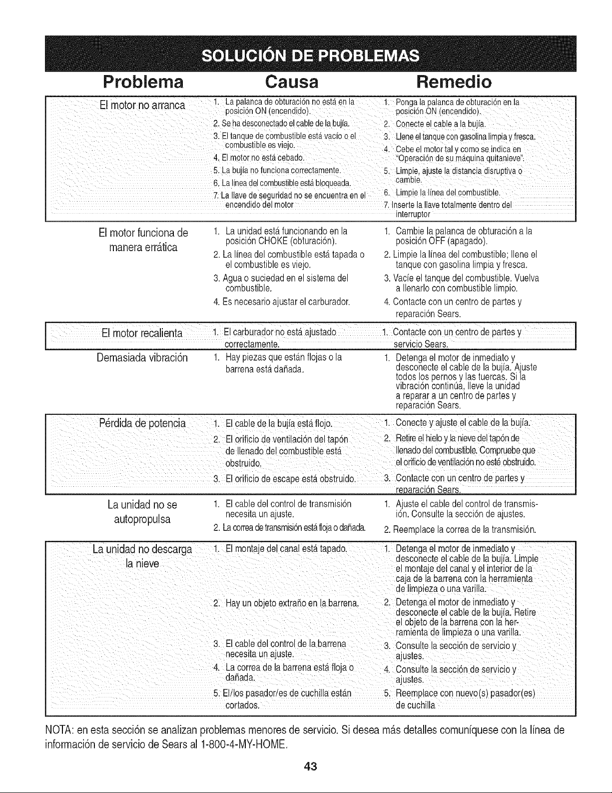
Problema Causa Remedio
El motnrno_rranc_ 1. Lapalancadeobturaci6nnoest_.enla 1 Ponga apaancadeobturac6nen a
" " "" posici6nON(encendido). posici6nON (encendido)i
2. Sehadesconectadoelcabledelabujfa. 2 Conectee cabea abufa
3. El tanquede combustibleest,.vacio o el 3. Ueneeltanquecongasolinalimpiay fresca:
c°rnbus!ib!ees ViejO_ Cebe el motortal y ComoSe indicaen
4, El motorno est,. cebado. ,Operaci6nde su m_.quinaquitanieve:
5. La bujia nofuncionaCorrectamentel 5. Limpie,ajustela distanciadisruptiva0
& Lalineadel combustib!eest,.blOquead& cambie,
7. haIlavede Seguridadno Seencuentraen el 6, Limpiela linea del combustib!e.
encendidodel motor 7: Insertela Ilavetotalmentedentrodel
interruptor
El motor funciona de
rnanera err_tica
1. La unidadestdtfuncionandoen la
posici6nCHOKE(obturaci6n).
2. LaIfneadelcombustibleestertapadao
el combustiblees viejo.
3. Aguao suciedaden el sistemadel
combustible.
4. Es necesarioajustarel carburador.
1. Cambie la palancade obturaci6na la
posici6nOFF (apagado).
2. LimpielaIfneadelcombustible;Ileneel
tanquecon gasolinalimpiay fresca.
3. Vade el tanquedel combustible.Vuelva
a Ilenarlocon combustiblelimpio.
4. Contactecon un centrode partesy
reparaci6nSears.
i El motor recalienta !. E!carburado[no estaajustado !. Contacteconuncentr0departesY
correctamente, servicioSears. J
Dernasiadavibraci6n 1. Haypiezasque est_mflojaso la 1. Detengael motorde inmediatoy
barrenaesterdahada, desconecteel cablede la bujia. Ajuste
todos lospernosy las tuercas.Si la
vibraci6ncontintJa,Ileve la unidad
a reparara un centrode partesy
reparaci6nSears.
P_rdida de potencia El Cabledela bujiaesta flojo. Conecte y ajusteel Cablede la buji&
2. ElorifiOiOdeVentilaci6ndeltap6n 2. Retireel hieloy ianievedeltap6nde
de !lenadode!€ombustibleest,. I!enadodelcombustible.Compruebeque
obstruidol elorifiCiodeventi!aci6nnoest6obstruido.
3. Elorificiode escapeestaobstruidol 3. Contacte€on UnCentrode partesy
re_araci6nSears.
La unidad no se 1. El cabledel controlde transmisi6n 1. Ajusteelcable delcontrolde transmis-
autopropulsa necesitaun ajuste, i6n.Consultela secci6nde ajustes.
2. Lacorreadetransmisi6nest_.flojaodahada. 2. Reemplacela correade la transmisi6n.
La unidad no descarga
a nieve
1. El montajedel canalestatapado.
2. Hayun objetoextrahoen la barren&
1. Detengael motorde inmediatoy
desconectee_cablede labujia. Limpie
el montajedel canal y el interiorde la
caja de la barrenacon la herramienta
de limpiezao unavarilla.
2. Detengael motorde inmediatoy
desconecteel cablede labujia. Retire
el objetode la barrenacon la her-
ramientade limpiezao unavarilla.
3. Elcabledelcontrolde la barrena 3. Consultelasecciondeservicioy
necesitaunajuste, aiustes.
4. Lacorreade la barrenaest,. flqa o 4. Consultelasecci6ndeservicloy
dahada, ajustes.
5. El los oasador/esde cuchillaest#.n 5. Reem#acecon nuevo(s)pasador(es)
cortados, de cuchilla
NOTA: en esta secci6n se analizan problernasrnenores de servicio. Si desea rn_.sdetalles cornuniquesecon la linea de
inforrnaci6nde servicio de Sears al 1-800-4-MY-HOME.
43

Your Home
For repair-in your home-of all major brand appliances,
lawn and garden equipment, or heating and cooling systems,
no matter who made it, no matter who sold it!
For the replacement parts, accessories and
owner's manuals that you need to do-it-yourself.
For Sears professional installation of home appliances
and items like garage door openers and water heaters.
1-800-4-MY-HOME ® (1-800-469-4663)
Call anytime, day or night (U.S.A. and Canada)
www.sears.com www.sears.ca
Our Home
For repair of carry-in items like vacuums, lawn equipment,
and electronics, call or go on-line for the location of your nearest
Sears Parts & Repair Center.
1-800-488-1222
Call anytime, day or night (U.S.A. only)
www.sears.com
To purchase a protection agreement (U.S.A.)
or maintenance agreement (Canada) on a product serviced by Sears:
1-800-827-6655 (U.S.A.) 1-800-361-6665 (Canada'
Para pedir servicio de reparaci6n Au Canada pour service en fran_;aB:
a domicilio, y para ordenar piezas: 1-800-LE-FOYER Mc
1-888-SU-HOGAR sM (1-800-533-6937)
(1-888-784-6427) www.sears.ca
S lrS
SM
® Registered Trademark / TM Trademark / Service Mark of Sears, Roebuck and Co.
TM SM
® Marca Registrada / Marca de F_brica / Marca de Servicio de Sears, Roebuck and Co.
MC MD
Marque de commerce / Marque d_pos_e de Sears, Roebuck and Co. ® Sears, Roebuck and Co.


