
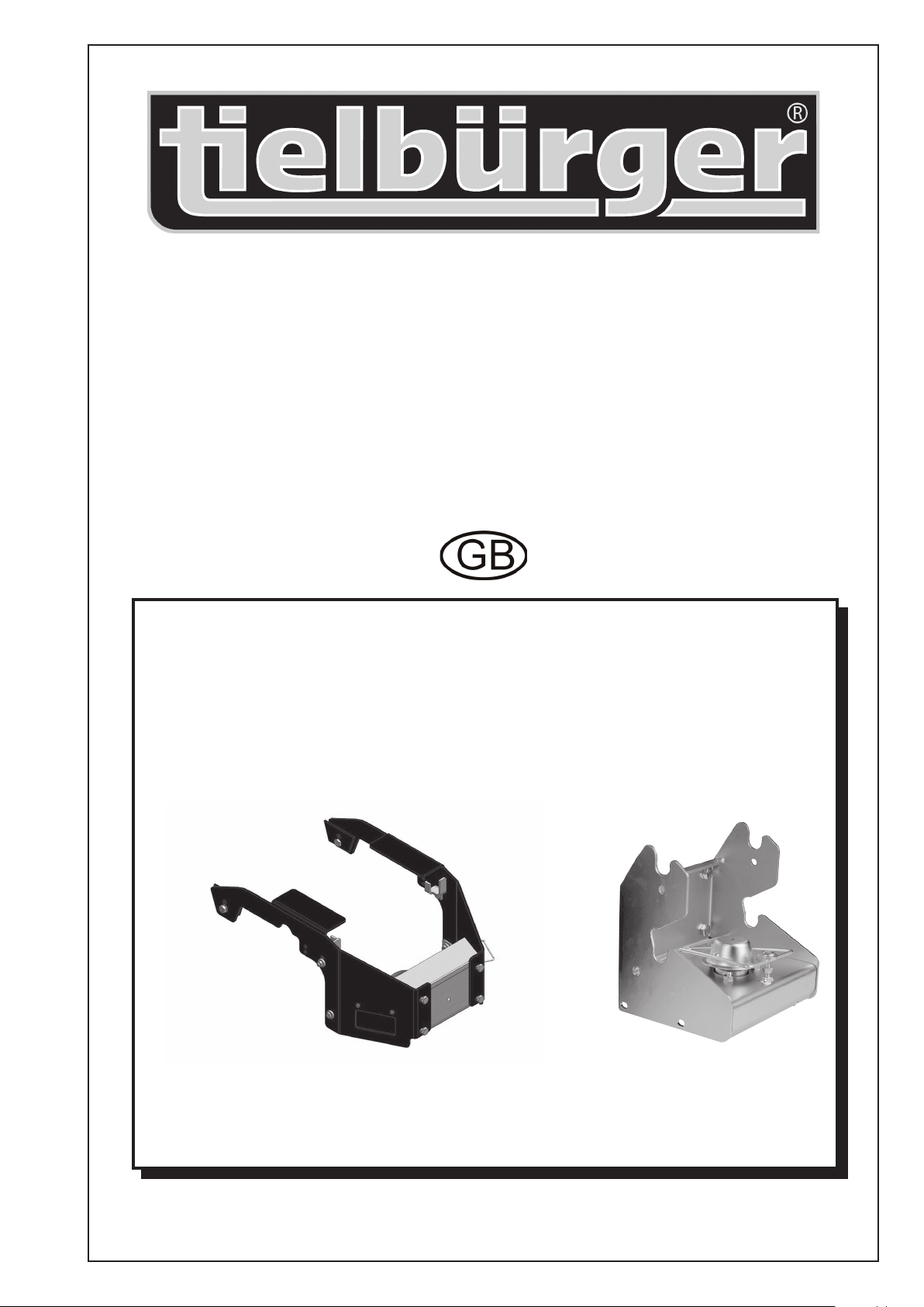
Mounting frame
AN-156-001GI
Copyright © 2016 by Julius Tielbürger GmbH & Co. KG, Stemwede Any reproduction, whether in whole or in part, is not permitted. KR-362-215GI REV. 00
Julius Tielbürger GmbH & Co. KG Maschinenfabrik
Postdamm 12 D-32351 Stemwede-Oppenwehe Germany Tel.: +49 (0) 57 73/80 20 Fax: +49 (0) 57 73/81 75
Website: www.tielbuerger.de
Operating and installation instructions
EN – Translation
171506097/0EN

This document is a publication by Julius Tielbürger GmbH & Co. KG, Postdamm 12, D-32351 Stemwede-Oppenwehe,
Germany (www.tielbuerger.de).
The document is up to date with the latest technology at the time of printing. Subject to technical and equipment changes. The
drawings and illustrations shown may differ from the original.
All rights reserved, including those of translation. Any type of reproduction, such as photocopy, microlm or storing in elec-
tronic data processing systems, requires written authorisation from the publisher. Any reproduction, whether in whole or in
part, is prohibited.
All trademarks, registered trademarks, trade names and brand names are the property of their rightful owners and are acknowl-
edged by us.
© Copyright 2016 by Julius Tielbürger GmbH & Co. KG

3
3
Content
1 Operating and installation instructions ....................................................................................................................... 4
1.1 General ..................................................................................................................................................................... 4
1.2 Warnings and symbols .............................................................................................................................................. 5
2 Basic safety instructions ................................................................................................................................................ 6
2.1 Intended use .............................................................................................................................................................. 6
2.2 Organisational measures ........................................................................................................................................... 6
2.3 Personnel selection and qualications; basic obligations ......................................................................................... 7
2.4 Position of safety stickers and labels ........................................................................................................................ 7
3 Scope and condition of delivery .................................................................................................................................... 8
4 Components of the Tielbürger quick-change system .................................................................................................. 9
4.1 Attachment sets for lawn tractors ............................................................................................................................. 9
4.2 Components of the Tielbürger quick-change system ............................................................................................... 9
4.3 Accessories ............................................................................................................................................................... 9
5 Installation .................................................................................................................................................................... 10
5.1 Preparatory measures prior to installation .............................................................................................................. 10
5.2 Installation .............................................................................................................................................................. 11
5.3 Installing the mounting frame ................................................................................................................................ 12
6 Start-up ......................................................................................................................................................................... 23
6.1 Basic safety instructions for normal operation ....................................................................................................... 23
7 Maintenance and care .................................................................................................................................................. 24
7.1 Basic safety instructions ......................................................................................................................................... 24
8 Transport ...................................................................................................................................................................... 25
9 Potential faults and how to rectify them .................................................................................................................... 25
10 Exploded drawings .................................................................................................................................................... 26
11 EC Declaration of Conformity .................................................................................................................................. 28

1.1 General
Operating and installation instructions
1 Operating and installation instructions
4
The operating and installation instructions are intended
to help users familiarise themselves with the machine
and use it in line with its intended applications.
The operating and installation instructions contain
important information on how to operate the machine
safely, properly and economically. Observing these
operating and installation instructions helps to avert
risks, to reduce repair costs and downtime and to
increase the reliability and service life of the machine.
The operating and installation instructions must always
be available at the location where the machine is used.
The operating and installation instructions must be read
and applied by any person in charge of carrying out
work with or on the machine, for example:
-Operation, including setting up, fault rectication in
the course of work, removal of production waste,
maintenance and disposal of operating and auxiliary
materials
-Maintenance (servicing, inspection, repair) and/or
-Transport.
The generally recognised rules of technology for safe
and proper working must be observed in addition to the
operating and installation instructions and mandatory
regulations for accident prevention which apply to the
country and place of use.
1.2 Warnings and symbols
CAUTION:
Indicates a potentially hazardous situation. If this instruction is ignored, there may be a risk
of minor injury.
IMPORTANT:
Indicates operating tips and other useful information.
5
Operating and installation instructions
WARNING:
Indicates a potentially hazardous situation. If this instruction is ignored, there may be a risk
of death or extremely serious injury.
DANGER!
Indicates an immediate threat of danger. If this instruction is ignored, there is a risk of death
or extremely serious injury.
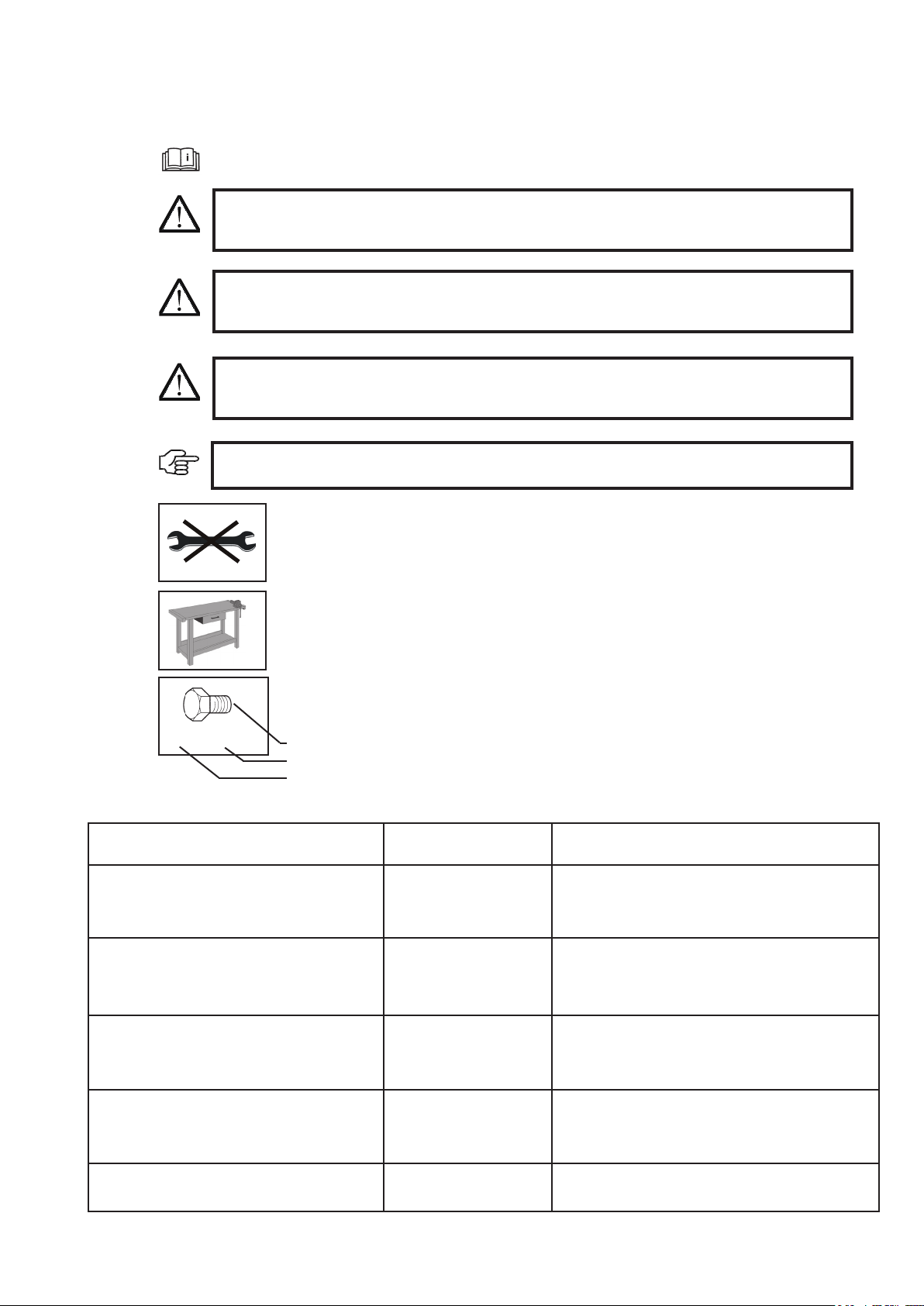
Do not use a tool
Work on a workbench
2x M8 x 20
Symbol
Type
Quantity
Read the operating and installation instructions
Symbol Example
types:
Explanation
Bolt M8 x 16 M = Metric
S = Diameter in mm
16 = Length in mm
Washer 8.1 - 58 - 5 8.1 = Inner diameter
58 = Outer diameter
5 = Material thickness in mm
Nut M8 (L) M = Metric
8 = Inner diameter in mm
(L) = Lock nut
Combination spanner
Hexagon head screwdriver
Screwdriver
8 8 = Size in mm
Crosshead screwdriver PZ 2
PH 2
PZ 2 = Pozidriv size 2
PH 2 = Phillips size 2

2.2 Organisational measures
2.1 Intended use
Basic safety instructions
2 Basic safety instructions
6
The product has been constructed using state-of-the-art
technology and in line with the recognised technical
safety regulations. However, use of this product may
still result in the risk of injury or death to the user or
third parties, or of damage to the product and other
material assets.
Only use the product in technically perfect working
order, for its intended use and with safety and hazards
in mind, in compliance with the operating and instal-
lation instructions. In particular, you must immediately
rectify faults that could impair safety or have such
faults rectied immediately by a third party.
The product is exclusively intended to be installed
on the machines approved by the manufacturer and is
intended for the accessories approved by the manufac-
turer. Any other or additional form of use, for example
use in conjunction with self-constructed accessories,
shall be regarded as non-compliant with the intended
use. The manufacturer/supplier shall not be held liable
for any damage or loss suffered as a result. The risk is
borne solely by the user.
When operating implements, the mower must be
switched off.
Do not mow on slopes with a gradient of more than
10° (17%).
Please note that no slopes are entirely safe. Driving on
slopes requires you to pay particular attention in order
to prevent the machine from overturning.
Intended use also includes complying with the oper-
ating and installation instructions and adhering to the
inspection and maintenance conditions.
The operating and installation instructions must always
be kept ready at the location where the machine is used.
In addition to the operating and installation instruc-
tions, observe and follow the generally valid legal reg-
ulations and any other binding regulations for accident
prevention and environmental protection.
Such obligations may also include handling hazard-
ous substances or making available/wearing personal
protective equipment and complying with road trafc
regulations, for example.
Supplement the operating and installation instructions
by instructions as well as site management and report-
ing obligations concerning special operational require-
ments, for example with regard to work organisation,
workows, personnel used, etc.
Any personnel instructed to perform work on the ma-
chine must have read the operating instructions before
starting work, specically the section entitled "Safety
instructions". Reading the instructions after work has
begun is too late. This applies in particular to person-
nel who only work on the machine occasionally, for
example for set-up and maintenance.
At least occasionally, check that the personnel are
working with safety and hazards in mind while fol-
lowing the operating instructions.
Personnel must not have long hair which is not tied
back or wear loose clothing or jewellery including
rings. There is a risk of injury from being caught or
drawn into the machine, for example.
Wear personal protective equipment if necessary or
required by regulations.
Observe all safety and hazard notices on the machine.
Ensure that all safety and hazard notices at/on the
machine can be read in full at all times.
In the event of any modication to the machine or any
change in the machine's performance that may affect
safety, shut down the machine immediately and report
the fault to the responsible specialist dealer.
Do not modify, convert or attach equipment to the
machine without approval from the manufacturer if
this could impair safety. This also applies to tting and
adjusting safety equipment and valves, as well as for
welding on supporting parts.
Use only genuine spare parts from the manufacturer.
These comply with the technical requirements and
safeguard your warranty and guarantee rights. Adhere
to the prescribed time periods or those indicated in the
operating and installation instructions for recurring
tests/inspections.
Workshop equipment which is appropriate for the work
is mandatory for carrying out maintenance measures.
Make personnel aware of the location of re extin-
guishers and how to use them.
Comply with the re alarm and reghting procedures.
7
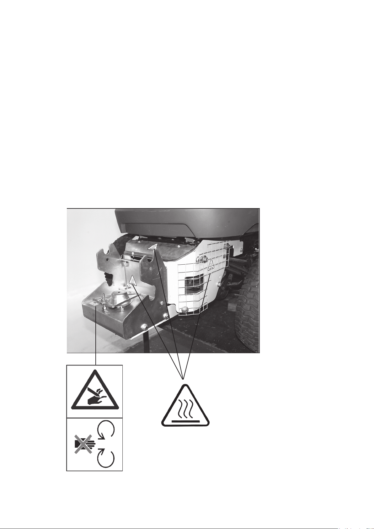
2.4 Position of safety stickers and labels
2.3 Personnel selection and qualications; basic obligations
Basic safety instructions
Caution:
Hot surface
Do not open the pro-
tective equipment
Work on/with the product may only be carried out by
reliable personnel. Observe the legal minimum age.
Only use trained or instructed personnel and clearly
dene the responsibilities of the personnel for opera-
tion, set-up, maintenance and repair.
Ensure that only authorised personnel work on the
product.
Only allow personnel who are yet to complete training,
instruction and induction or who are still completing a
general apprenticeship to carry out work on the prod-
uct under the constant supervision of an experienced
person.
Work on the product's electrical equipment may only
be carried out by a qualied electrician or by trained
personnel under the guidance and supervision of a
qualified electrician in accordance with electrical
engineering regulations.
Work on chassis, braking and steering systems must
only be carried out by qualied personnel trained for
such work.
Only personnel who possess specic knowledge of
and experience in hydraulics are allowed to carry out
work on hydraulic equipment.
Clean the implement regularly, particularly in the ex-
haust and engine area. Otherwise, there is an increased
risk of re.

Scope and condition of delivery
8
Scope of delivery
Check the attachment sets supplied to ensure that they match the specied scope of delivery.
The transport packaging should be recycled.
3 Scope and condition of delivery
Product packaging Inspection of the original packaging
Mounting frame AN-156-001GI

The Tielbürger quick-change system
9
4.1 Attachment sets for lawn tractors
4 Components of the Tielbürger quick-change system
For implements:
with a drive: Mounting frame AN-156-001GI
Quick-change mechanism with drive AN-001-003TS
4.2 Components of the Tielbürger quick-change system
4.3 Accessories
Ask your authorised Tielbürger specialist dealer for the latest implements.
You can nd further information on our website: www.tielbuerger.de
Mounting frame Quick-change mechanism
with drive
1 2
Clearing blade ts125 Greenkeeper 110
Minimum requirement
1 + 2
Minimum requirement
1 + 2
Installation
Installation should be performed on a height-adjustable work platform in accordance with the following instruc-
tions.
10
5.1 Preparatory measures prior to installation
5 Installation
IMPORTANT:
Comply with the safety regulations for the work platform.
DANGER!
There is an increased risk of injury near running drives. Follow the safety instructions.
IMPORTANT:
The construction sets supplied must be checked to ensure that they are complete using the spare
parts list in these instructions.
The quick-change system should only be installed by a specialist dealer of engine units.
Before you begin, acquire an overview of the installation sequence and the required parts and tools.
The machine must be clean and in technically correct working order.
Follow the lawn tractor manufacturer's safety instructions and operating instructions.
WARNING:
Switch off the engine and allow it to cool down. The machine must be secured to prevent it from being
started inadvertently. Remove the ignition key and activate the parking brake.
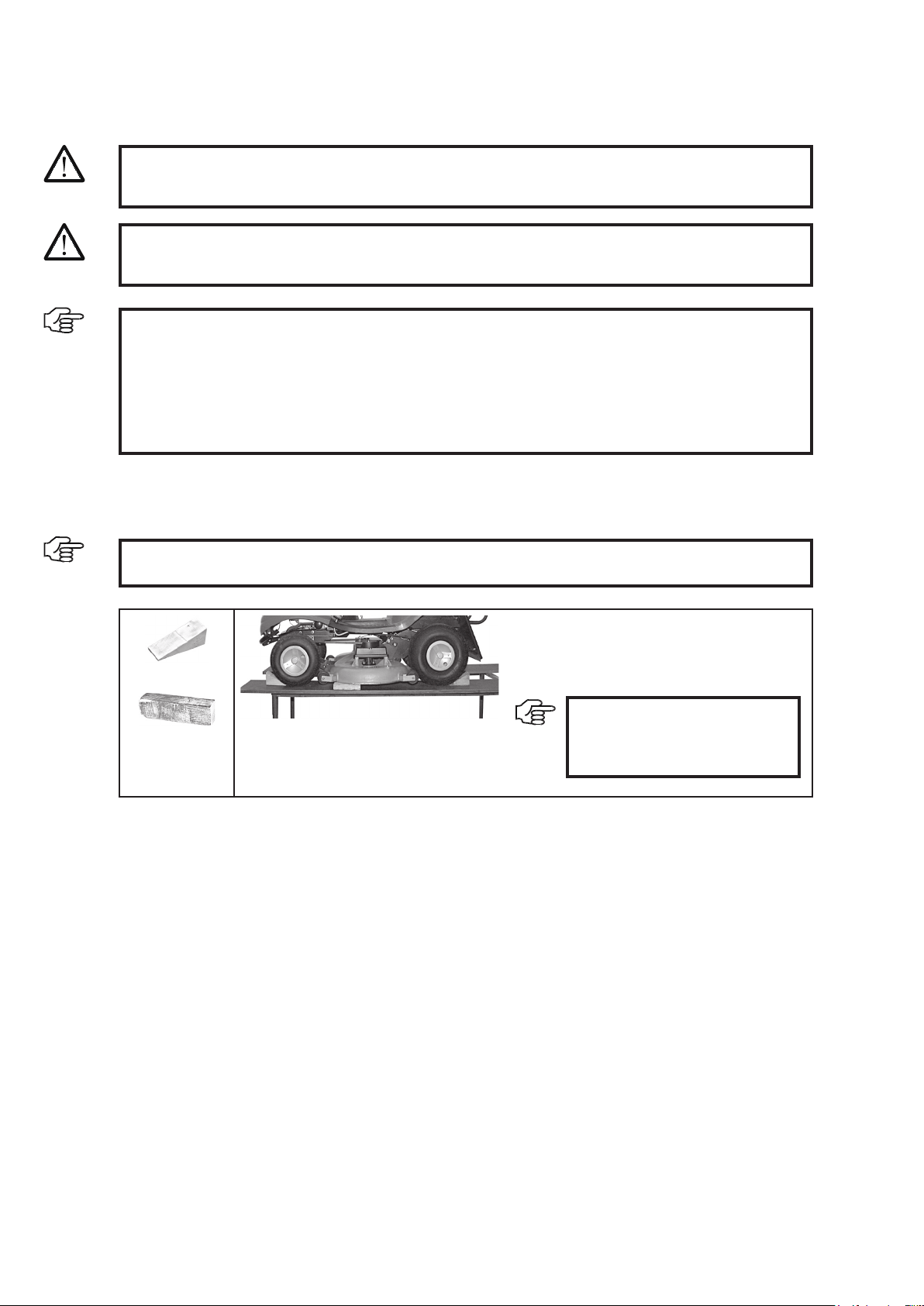
2x
Lower the mower on to timber.
Secure the lawn tractor against rolling away by
using wheel chocks.
1x
IMPORTANT:
Follow the operating instructions
provided by the manufacturer
for this.
11
Dear valued customer,
Models are continuously being updated by the lawn tractor and implement manufacturers in line with technolog-
ical progress. As a result, descriptions or illustrations in these instructions may differ from the actual conditions
on the lawn tractor.
Select one of the columns below on the basis of your mounting frame.
Column A = Attachment parts without quick-change mechanism,
for securely attached accessories
Column B = Attachment parts with quick-change mechanism,
for non-driven implements (e.g. clearing blade)
Column C = Attachment parts with quick-change mechanism with drive,
for driven implements (e.g. sweepers) and
for non-driven implements
1) During installation, only those steps which are marked with a point • in the selected columns have to be carried
out. Highlight the column that applies using a highlighter.
2) The sequence given in the installation instructions must be complied with.
Installation
5.2 Installation
DANGER!
It is necessary to remove protective equipment in order to install attachment parts. You must there-
fore ensure that this equipment is reattached after installation is complete. This is why none of the
following work steps can be ignored.
DANGER!
The installation procedure described below must only be performed by the specialist dealer.

Installation
12
A B C
Read the user manual provided by the lawn tractor
manufacturer.
Complete mounting frame.
Open the bonnet.
Release the plug connec-
tion to the lights.
Remove the bonnet.
Remove the guard plate.
Removed parts which
can or cannot be reused.
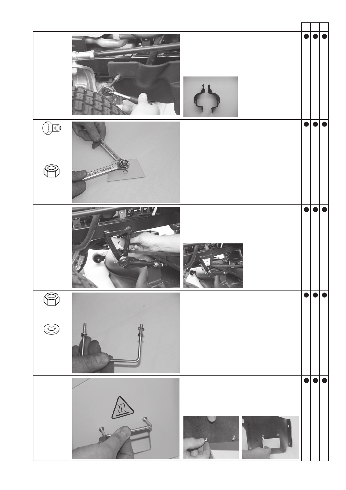
5.3 Installing the mounting frame
A B C
Remove the guard plate.
Removed parts which
can be reused.
1x M10 x 30
Pre-assemble the adapter with a bolt and nut.
1x M10
Position the adapter.
1x M10 x 30
Pre-assemble the bracket with a washer and nut.
4x 5.3-10-1
Fit the bracket to the support.
Turn the nut with washer on the bolt.
13
Installation
Installation
14
A B C
1x 10.5-20-2
Position the support.
1x M10
Turn the washer with nut
on the bolt.
Follow the same pro-
cedure for the opposite
side.
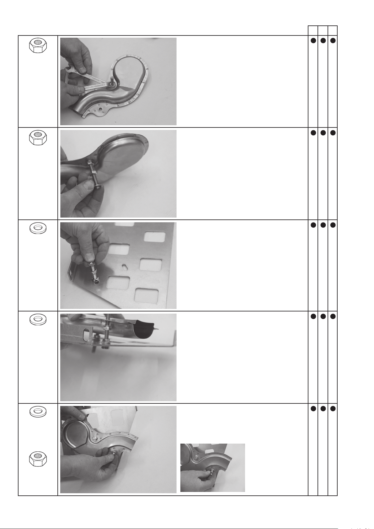
1x M8 x 25
Push the bolt with washer through the hole.
1x 8.4-21-4
Complete right counter-holder/left counter-holder
1x M8
Position the counter-holder.
Turn the nut on the bolt.
1x M8 x 60
Push the bolt with washer through the elongated
hole in the guard plate.
1x 8.4-16-1.6
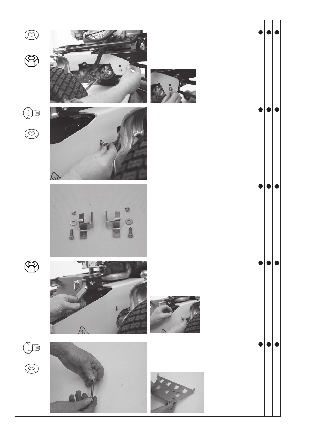
Installation
15
A B C
1x 8.4-16-1.6
Place the washer on the bolt.
1x M8
Turn the nut on to the bolt.
1x M8
Turn the second nut on to the bolt.
1x 8.4-16-1.6
Place the washer on the bolt.
1x 8.4-16-1.6
Push the bolt with washer through the hole.
1x M8 x 60
Installation
16
A B C
1x M8
Turn the nut on to the bolt and tighten.
1x M8
Turn the second nut on to the bolt.
1x 8.4-16-1.6
Place the washer on the bolt.
1x 8.4-16-1.6
Push the washer on to the exhaust system bolt and
push the bolt through the elongated hole on the
guard plate at the same time.
1x 8.4-16-1.6
Place the washer on the bolt.
1x M8
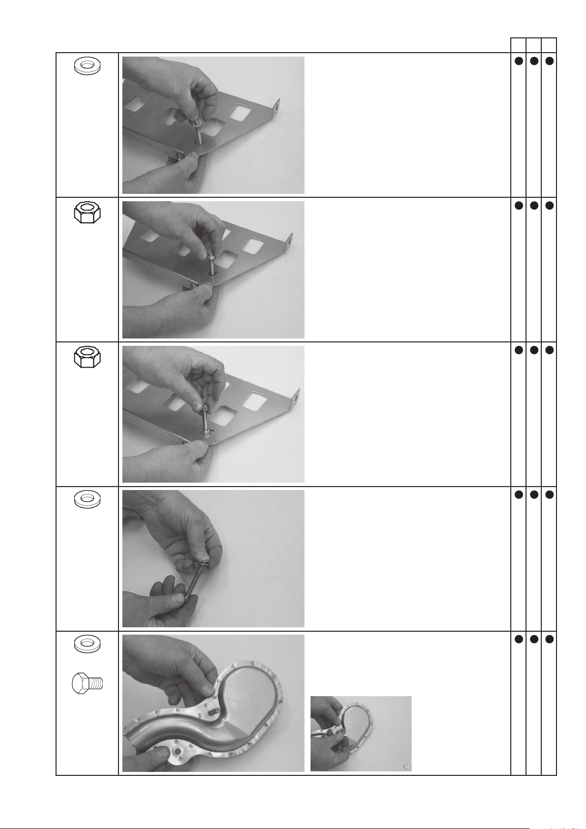
Installation
17
A B C
1x 8.4-16-1.6
Place the washer on the bolt.
1x M8
Turn the nut on the bolt.
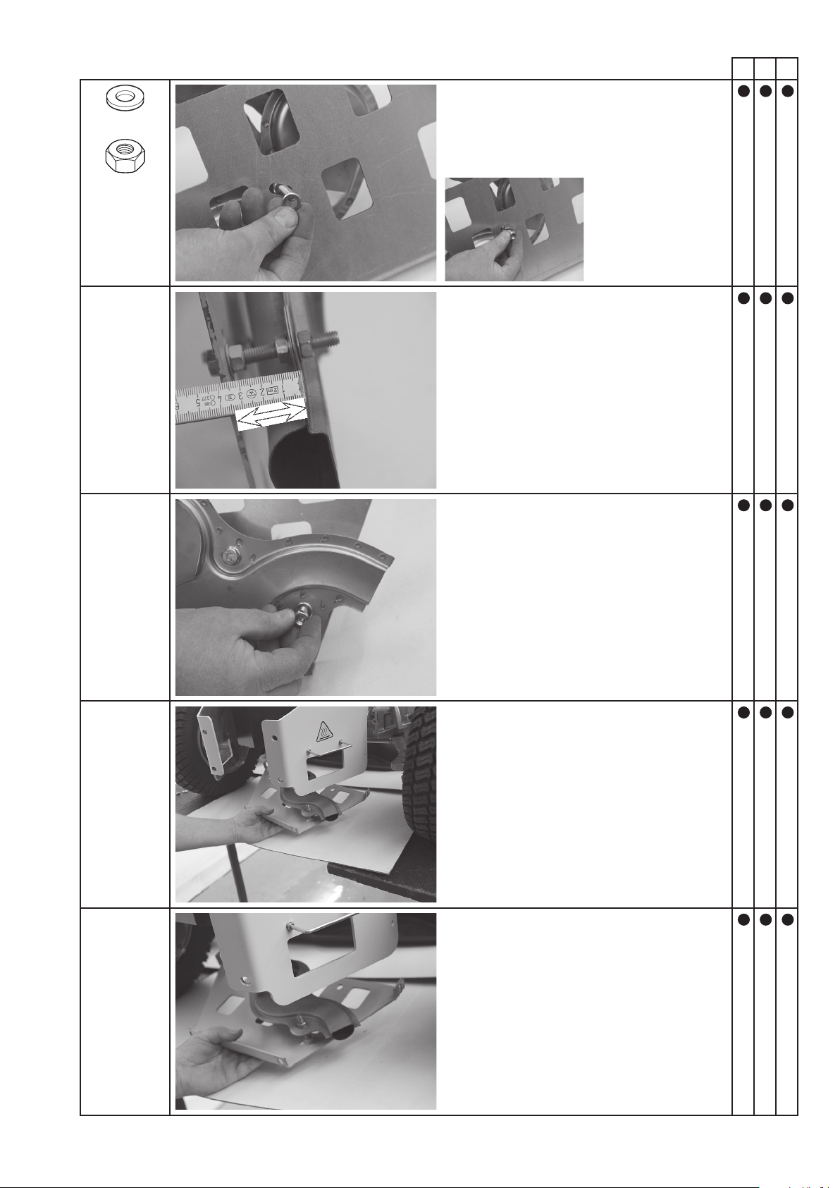
= 35 mm
Set the height of the exhaust system to 35 mm.
Tighten the nuts.
Install the exhaust system with the guard plate on
the support.
Position the exhaust system with the guard plate.
Installation
18
A B C
2x M8 x 25
Push the bolt with washer through the elongated
hole in the support and guard plate.
2x 8.4-21-4
2x M8
Loosely t the guard plate with nut and washer to
the support. In this case, on the left in relation to
the direction of travel.
Install the opposite side in the same way.
2x 8.4-21-4
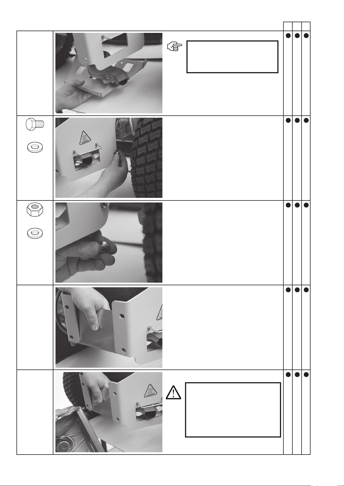
Position the guard plate.
IMPORTANT:
Slide the opening in the exhaust
system on to the lawn tractor's
deector.
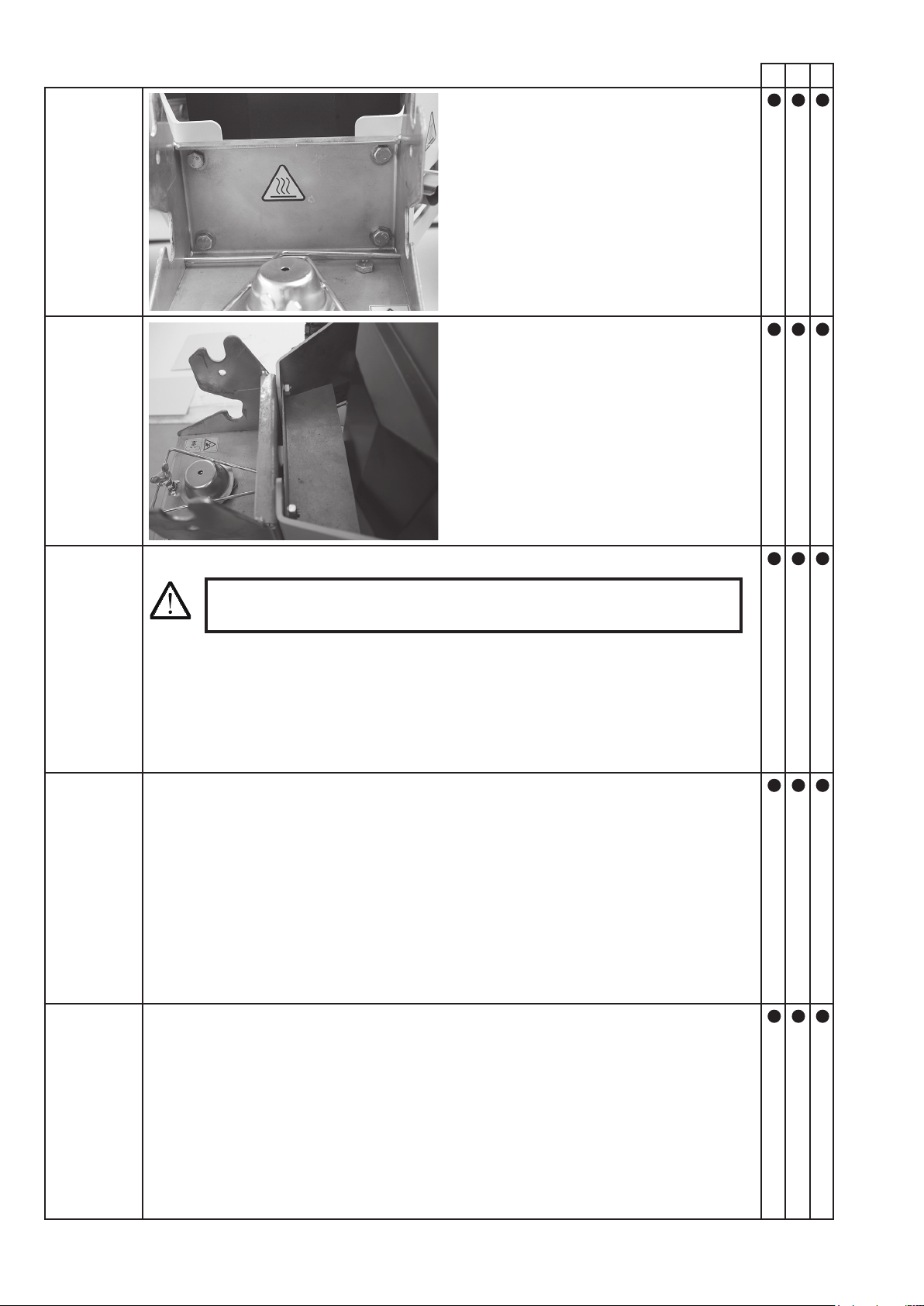
WARNING:
When installing the quick-change
mechanism, ensure that the surfaces
of the exhaust system and exhaust
pipe are positioned exactly on top
of one another. There is otherwise
a risk of heat accumulation.

Installation
19
A B C
Position the quick-change mechanism.
2x M10 x 25
Install the quick-change mechanism with a washer,
bolt and nut.
2x M10
2x 10.5-20-2
Position the nger guard.
2x M10 x 25
Install the nger guard with a washer, bolt and nut.
2x M10
2x 10.5-20-2
Tighten all bolts.
Installation
20
A B C
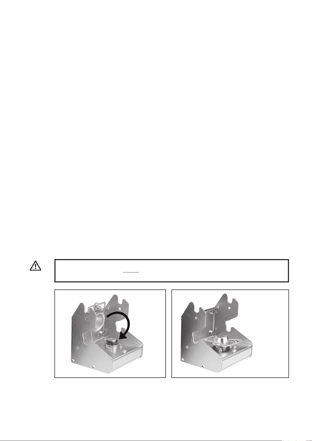
Correctly installed quick-change mechanism.
DANGER!
Ensure that all protective equipment is securely tted.
Installation
21
A B C
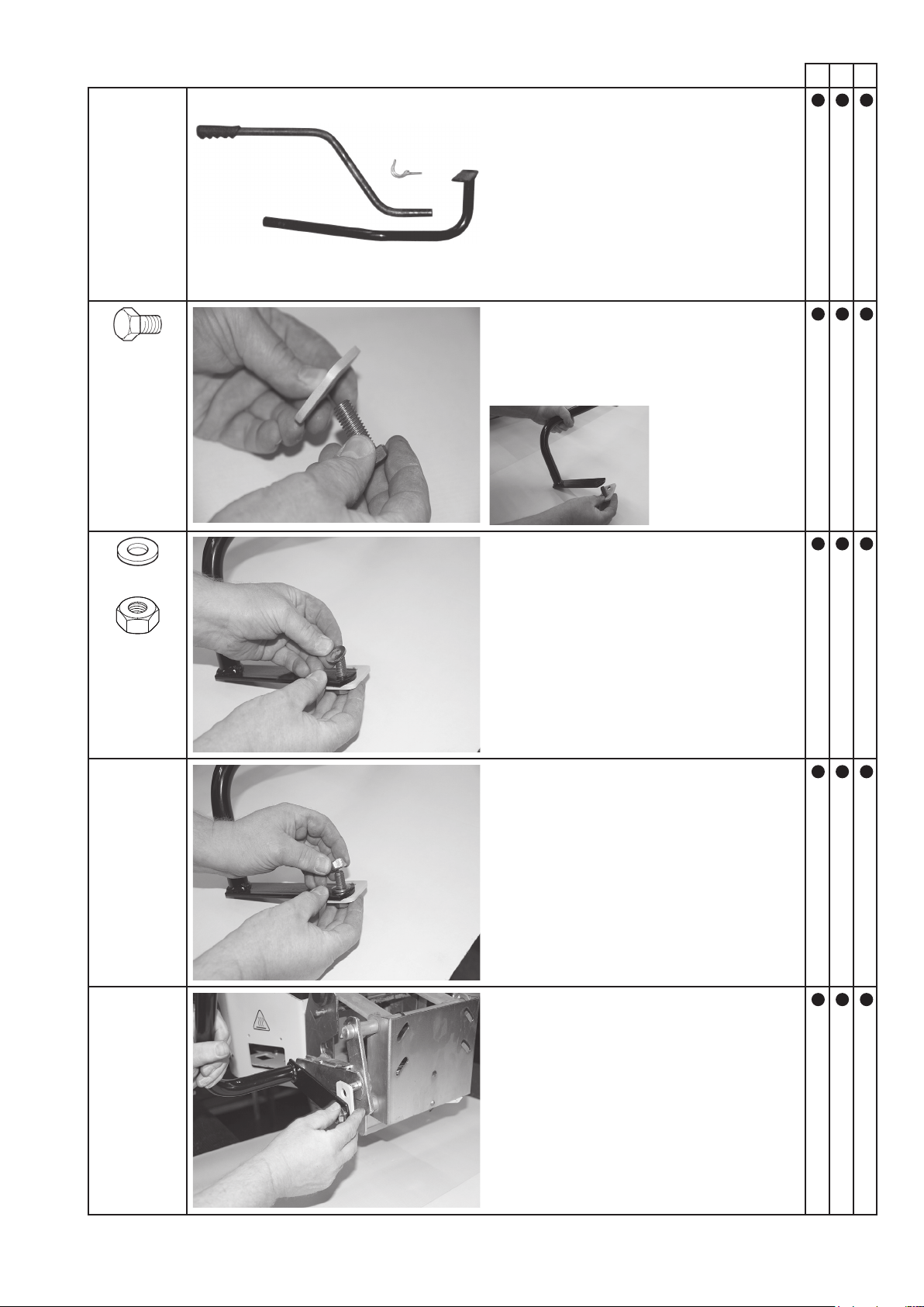
Assemble the operating lever.
1x M12 x 30
Push the bolt through the hole in the tab.
1x 13-24-2
Turn the washer and nut on the bolt.
1x M12
Put the lifting linkage in place.

Installation
22
A B C
Secure the linkage with an R-pin.
Tighten all bolts.
6.1 Basic safety instructions for normal operation
6 Start-up
Start-up
23
WARNING:
Before using the lawn tractor without an implement, cover the dog clutch on the quick-release coupling
with the guard and secure using the bolt.
Never operate the machine in a manner that could
compromise safety.
Before beginning work, familiarise yourself with the
work environment at the location where the machine
is used. The work environment includes, for example,
obstacles in the work and trafc area, the load-bearing
capacity of the oor and the required means of cordon-
ing the location where the machine is used off from
the public trafc area.
Take appropriate measures to ensure that the machine is
only operated in a safe and fully functional condition.
Only operate the machine when all protective equip-
ment and safety-critical equipment, for example
detachable protective equipment, sound-insulating
equipment and extraction equipment, is present and
in proper working order.
Always check for externally visible damage and defects
before using the machine. Report any changes that may
have occurred (including changes in performance) to
the specialist dealer immediately. Shut down the ma-
chine immediately and secure it if necessary.
In the event of a malfunction, shut down and secure
the machine immediately. Have faults rectied im-
mediately.
Only start the machine from the driver's seat.
Switch the machine on and off in accordance with the
installation instructions, observing the control displays.
Before switching on/starting up the machine, ensure
that no one can be endangered by the machine starting
up.
Before travelling with the machine or beginning work,
check that the brakes, steering, signal and lighting
systems are fully functional.
Before driving the machine, always check that ac-
cessories
have been tted such that they are accident-proof.
When driving on public roads and paths and in public
places, comply with the applicable road trafc regu-
lations and bring the machine into a condition which
is permitted by road trafc regulations in advance.
In poor visibility or in the dark, always ensure suf-
cient lighting.
Always maintain an adequate distance from pit edges
and slopes.
Prohibit any manner of working that may impair the
stability of the machine.
The machine must not be used on slopes with a gradient
of more than 10° (17%).
Do not drive across slopes; always transport work
equipment and loaded goods close to the ground,
particularly when descending hills.
Always adapt your driving speed to the conditions
on sloping terrain. Never change to a lower gear on a
slope; you should do this before you reach the slope.
Upon leaving the machine, always secure it against
accidentally rolling away and unauthorised use.
1) Close the protective ap. 2) Secure the protective ap using the bolt.

Maintenance and care
7.1 Basic safety instructions
7 Maintenance and care
24
IMPORTANT:
Check to ensure that
• No fuel or oil is leaking, and rectify if necessary
• Bolts and nuts are securely fastened, and tighten if necessary
• All moving parts run smoothly, and lubricate if necessary
DANGER!
Clean the implement regularly, particularly in the exhaust and engine area. Otherwise, there is an
increased risk of re.
Comply with the adjustment, maintenance and inspec-
tion tasks and intervals specied in the user manual,
including the information on replacing parts/equip-
ment. These tasks may only be carried out by qualied
personnel. See the maintenance schedule.
Inform operating personnel in advance before carrying
out special work and maintenance work. Name
the supervisors.
Switch the machine on and off in accordance with
the user manual and comply with the instructions on
maintenance work for all work that may affect opera-
tion, production adjustment, conversion or adjustment
of the machine and its safety-critical equipment, as
well as work involving inspection, maintenance and
repair. Cordon off a large area for maintenance work
if required.
The machine must be secured against being switched
back on inadvertently if it is completely switched off
for maintenance and repair work:
-Remove the key
-Afx a warning sign to the starter.
Only carry out maintenance and repair work when the
machine is parked on a level surface with sufcient
load-bearing capacity and when the machine is secured
against rolling away and overturning.
During replacement, individual parts and larger assem-
blies must be carefully attached and secured to lifting
gear such that they do not pose any risks. Only use
suitable lifting gear in technically perfect condition and
load-handling equipment with sufcient load-bearing
capacity. Do not stand or work under suspended loads.
Do not use machine parts as climbing aids.
Keep all handles and steps free from dirt, snow and ice.
Clean oil, fuel or care products from the machine, and
the connections and screw connections in this case in
particular, before starting maintenance/repair work.
Do not use aggressive cleaning agents. Use lint free
cleaning cloths.
Before the machine is cleaned with water, a high-pres-
sure cleaner or other cleaning agents, all openings
which must not allow water/vapour/cleaning agents to
penetrate for reasons of safety or operational function-
ing must be covered over or sealed. Electric motors and
other live components are particularly at risk.
After cleaning, the covers and seals must be completely
removed.
After cleaning, inspect all fuel and oil lines for leaks,
loose connections, areas of abrasion and damage. Im-
mediately rectify any defects that have been identied.
Always retighten screw connections that have come
loose during maintenance or repair work.
If safety devices need to be removed during set-up or
maintenance and repair work, they must be reinstalled
and tested immediately after the maintenance and
repair work has been completed.
Ensure that operating and auxiliary materials and
replacement parts are disposed of safely and in an
environmentally friendly manner.
Electrical equipment on a machine must be inspected/
tested on a regular basis. Defects, such as loose connec-
tions and burnt cables, must be rectied immediately.
When working on high-voltage assemblies, connect
the supply cable to earth after the power has been
disconnected and short-circuit the components, e.g.
capacitors, using an earthing rod.
Never allow combustion engines to run in closed or
conned spaces. The exhaust gases contain poisonous
carbon monoxide gas.
Comply with the regulations which apply to the site
of use in question.
Only carry out welding, open-ame and grinding work
on the machine if this has been expressly approved.
For example, there may be a risk of re or explosion.
Before welding, open-ame and grinding work is
carried out, remove dust and combustible materials
from the machine and its surrounding area and ensure
that there is sufcient ventilation (risk of explosion).
Check all lines, hoses and screw connections regularly
for leaks and signs of external damage. Rectify any
damage immediately. Oil escaping under pressure may
result in injuries and res.
Noise insulation equipment on the machine must be in
the protective position during operation.
Wear the prescribed personal hearing protection.
Observe the safety instructions which apply to the
product when handling oils, greases and other chemical
substances.
Take care when handling hot operating and auxiliary
materials (risk of burning or scalding).

Transport
8 Transport
25
DANGER!
If the machine is to be transported on a lorry or trailer, loading ramps with a suitable load-bearing capacity,
width and length must be used. The machine must only be loaded with the engine switched off, without a
driver, by being pushed on to the means of transport by an appropriate number of people. During trans-
port, close the petrol cock (if present), lower the cutting disc, apply the parking brake and appropriately
secure the machine on the means of transport with ropes or chains.
9 Potential faults and how to rectify them
IMPORTANT:
If a fault which is not listed in this table occurs, contact the specialist dealer. Once you have tried all of
the corrective measures described here with no success, contact the specialist dealer.
IMPORTANT:
Only use genuine spare parts from the manufacturer, which you can obtain from your specialist dealer.
This ensures that the implement will work reliably.
Fault Cause Corrective measure
V-belt running not OK V-belt pulley installed
incorrectly
Check the centring of the V-belt pul-
ley; the contact surfaces must be clean
and free of burr
Grinding sounds V-belt does not run over the V-belt
tensioner
Position the V-belt and V-belt ten-
sioner according to the installation
instructions
Premature V-belt wear The V-belt edges
and the V-belt idler pulley are
touching
Reposition the V-belt tensioner ac-
cording to the instructions

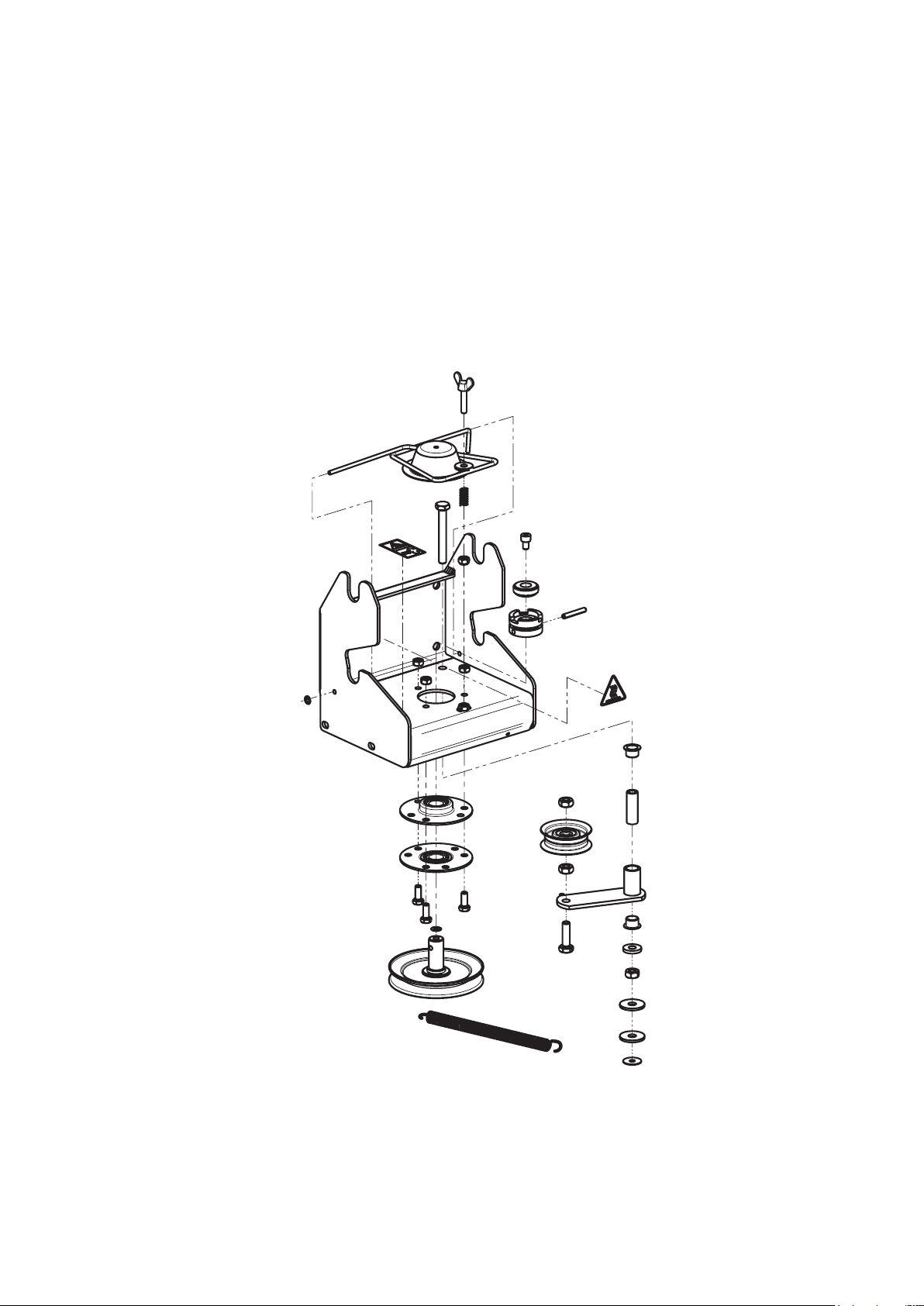
10 Exploded drawings
IMPORTANT:
The "Remarks" column helps you to identify parts.
Only use genuine spare parts from the manufacturer. This ensures that the implement will work reliably.
Item numbers in brackets are wear parts.
Exploded drawings
26
27
Exploded drawings

EC Declaration of Conformity
(in accordance with EC Directive 2006/42/EC)
Manufacturer: Julius Tielbürger GmbH & Co. KG
Maschinenfabrik
Postdamm 12
D-32351 Stemwede-Oppenwehe, Germany
Authorised representative for technical documentation:
Mr Jörg Tielbürger
Julius Tielbürger GmbH & Co. KG
Maschinenfabrik
Postdamm 12
D-32351 Stemwede-Oppenwehe, Germany
We hereby declare that the Tielbürger system:
Attachment parts Serial no.: AN-156-001GI
in combination with:
Sweeper Serial no.: AD-200-001GI
Clearing blade Serial no.: AE-015-001GI
Snow chains Serial no.: KC-002-008
Greenkeeper Serial no.: AI-200-001GI
complies with all relevant provisions of EC Machinery Directive 2006/42/EC as replaceable
equipment for installation on the following ride-on mowers:
TWIN CUT HIGH-END mod. TH(4)x 102 SERIES
TWIN CUT HIGH-END mod. TH(4)x 122 SERIES
TWIN CUT HIGH-END mod. TH(4)x 118 SERIES
for cleaning surfaces.
Stemwede, 12.10.16
Julius Tielbürger
GmbH & Co.KG
….................................
L. Tielbürger
(Managing Director)
KR-362-215GI
28
11 EC Declaration of Conformity
28