Loading ...
Loading ...
Loading ...
- The water must be connected to the appliance via a cold
water pipe that can withstand the operating pressure and
complies with hygiene standards.
Use the stainless steel hose supplied (length 1.5 m). Do not
reuse old hoses. A 3 m hose is available as an optional
extra. This must be professionally installed.
A filter with a seal is located in the hose connector.
- A stopcock must be provided between the hose line and the
domestic water connection to cut off the water supply if
necessary.
- The stopcock must be located outside the back of the appli-
ance and be within easy reach so that the appliance can be
inserted as deeply as possible and the stopcock can be
turned off quickly. Stick to the clearances.
- All devices and equipment used to supply water must
comply with the regulations in force in the respective
country.
- Do not damage or kink the water supply line during installa-
tion.
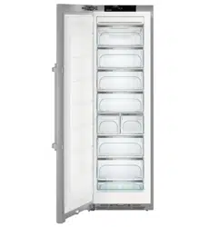
Fig. 28
The solenoid is located at the bottom on the back of the appli-
ance. It has a metric R3/4 connecting thread.
For specialist staff:
Connecting the stainless steel hose: The back of the appliance
must be accessible.
WARNING
Broken auxiliary tool
Fig. 28 (6)
.
Cuts.
u
Only use an auxiliary tool
Fig. 28 (6)
at room temperature.
Connecting the hose to the appliance:
u
Remove the cover
Fig. 28 (2)
.
u
Easy to fit: Place the straight end of the hose
Fig. 28 (8)
to
the left on the floor.
u
Slide the nut
Fig. 28 (5)
over the angled end of the hose
Fig. 28 (4)
up to the end and secure.
u
Moisten
Fig. 28 (3)
the seal and push onto the nut
Fig. 28 (5)
.
w
The seal
Fig. 28 (3)
lies flat and is easily retained.
Fig. 29
NOTICE
Damaged solenoid thread pitch.
The solenoid leaks: Water may leak out.
u
Position the nut
Fig. 29 (1)
carefully and screw it directly
onto the thread with two fingers until it is seated securely.
u
Tighten the nut
Fig. 29 (1)
clockwise with the auxiliary tool
Fig. 28 (6)
until maximum torque is reached and the auxiliary
tool
Fig. 28 (6)
overtightens.
Connecting the hose to the stopcock:
u
Screw the nut
Fig. 28 (8)
onto the stopcock
Fig. 28 (9)
.
u
Tighten the nut
Fig. 28 (8)
clockwise with the auxiliary tool
Fig. 28 (6)
until maximum torque is reached and the auxiliary
tool
Fig. 28 (6)
overtightens.
u
Turn the water supply stopcock
Fig. 28 (9)
on and check the
whole water system for leaks.
u
Flushing the IceMaker: Turning the IceMaker on chapter
(see 5.15.2) .
u
Hook the clip
Fig. 28 (7)
into the auxiliary tool
Fig. 28 (6)
and
fix it to the stainless steel pipe to store it.
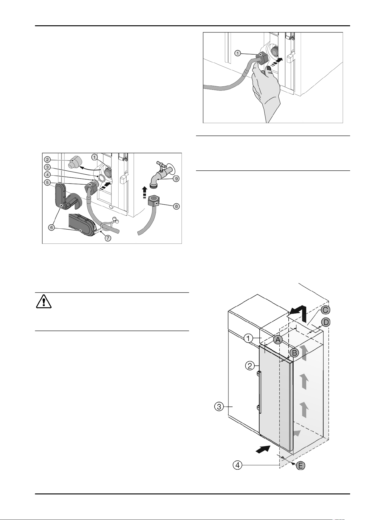
4.5 Insertion into a row of kitchen units
Fig. 30
For 600 mm wide appliances:*
Putting into operation
14 * Depending on model and options
Loading ...
Loading ...
Loading ...