Loading ...
Loading ...
Loading ...
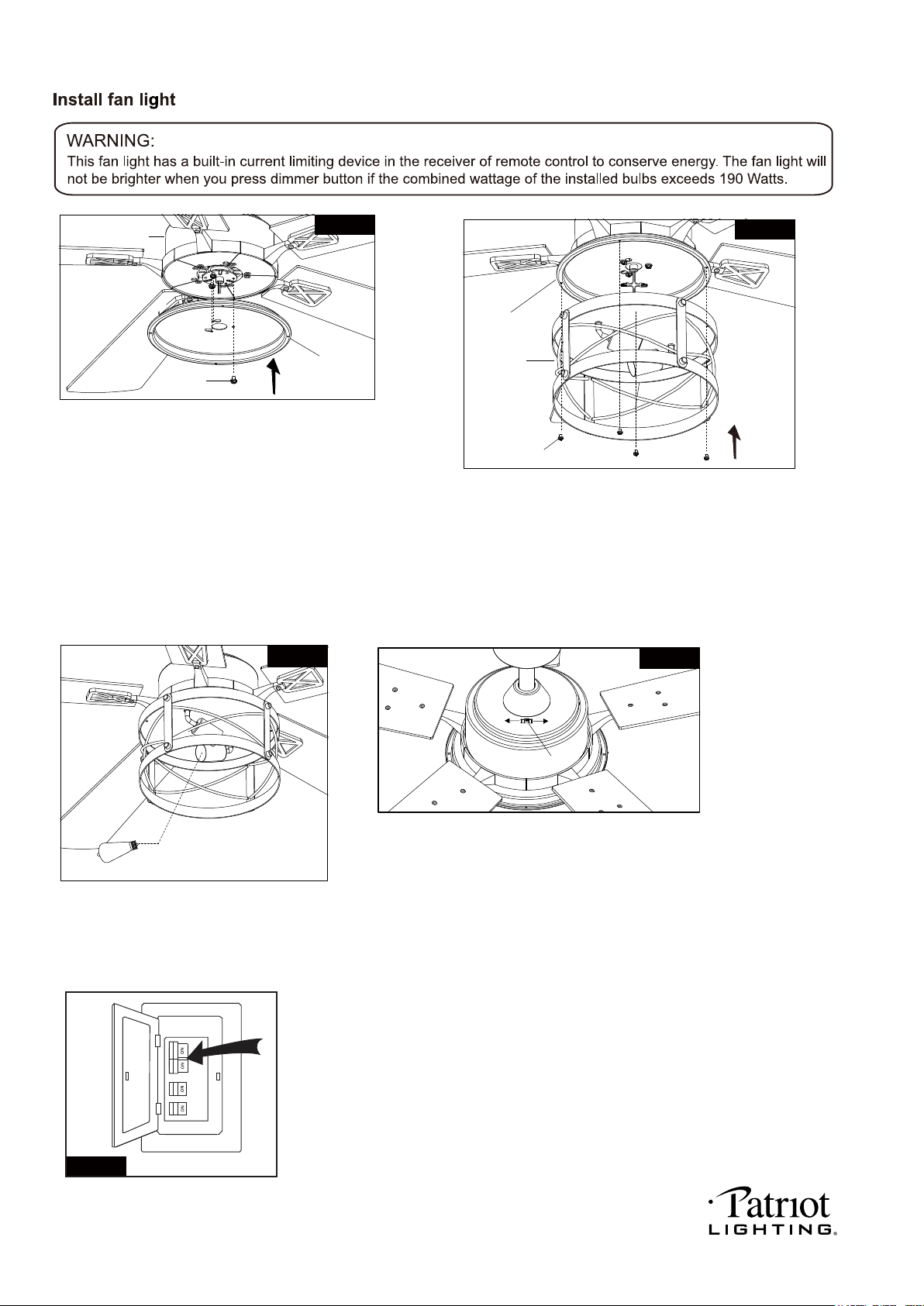
Fan Motor
Assembly Screw
Fan Motor Assembly
Connect Plate of
Light Kit
Fig.16
Fig.17
Light Kit
Slide Switch
Forward
Severse
Fig.19
Remove one screw and loosen another two screws
from fan motor assembly first, thread the fan motor
assembly wires through connect plate of light kit
then push the connect plate of light kit upwards
until the fan motor assembly screws insert into
the key hole slots of connect plate of light kit then
rotate the connect plate of light kit until it’s fixed
on the fan motor assembly bottom. Finally, secure
the connect plate of light kit to the fan motor assembly
bottom with previous screw which was removed.
Tighten the other two fan motor assembly screws.
Remove four connect plate screws from connect
plate of light kit first. Then connect the white (neutral)
wire from the light kit to white (neutral) wire from connect
plate of light kit with a wire connector; connect the black
(hot) wire from light kit to blue (hot) wire from connect
plate of light kit with a wire connector. Carefully put the
wires into the connect plate of light kit , then attach the
light kit onto the connect plate of light kit with the connect
plate screws.
Install LED bulbs (included).
See relamping label at socket area or
packaging for maximum allowed wattage.
Connect Plate
of Light Kit
Connect Plate Screws
The slide switch on fan motor assembly sets
direction of fan rotation. Select the desired
direction of fan rotation. Push the slide switch
left for "Forward" and right for "Reverse".
Note: Wait for fan to stop before reversing the
direction of blade rotation.
Fig.18
2-6W E26 ST19 LED Blubs Included
E26 ST19 Blubs Max.60W
Fig.20
Turn ON the electric power at the
main fuse or circuit breaker box.
PAGE: 8 / 12
201202
Loading ...
Loading ...
Loading ...