Loading ...
Loading ...
Loading ...
S ...........CE ADJUST ..........TS
......... ..... Jl iiiii u i iiiiiii ,111,,,i / ,, ................ii : : : ................................... .
TO ADJUST THE BELT GUIDES ...................... .........................
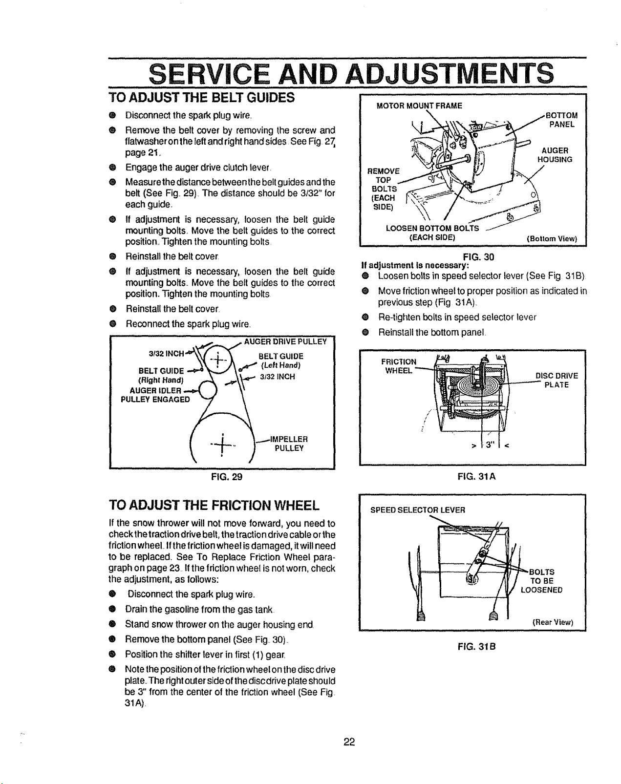
MOTOR MOUNT FRAME
® Disconnect the spark plugwire.
® Remove the belt cover by removing the screw and
flatwasheron the leftand right hand sides See Fig 27,
page 21_
Q Engage the auger drive clutch lever.
® Measurethe distance betweenthe belt guides and the
belt (See Fig..29). The distance should be 3/32" for
each guide.,
@ tf adjustment is necessary, loosen the belt guide
mounting bolts. Move the beit guides to the correct
position,.Tighten the mounting bolts.
® Reinstall the belt cover.
® If adjustment is necessary, loosen the belt guide
mounting bolts. Move the belt guides to the correct
position. Tighten the mounting bolts
®
®
REMOVE
TOP
BOLTS
(EACH
(EACH SLOE)
FIG. 30
If adjustmentis necessary:
PANEL
AUGER
HOUSING
(Bottom View}
® Loosen bolts in speed selector lever (See Fig 31B)
• Move friction wheel to proper positionas indicatedin
previous step (Fig 3tA)..
Re-tighten bolts in speed selector lever
Reinstall the bottom panel.
Reinstall the belt cover.
Reconnect the spark plug wire.
........" : ......... ,--_ -,,-,,_,...__ AUaER_RiVEPULLEY
1NCH'W_ ._,.,. _ BELT GUIDE
3132
,4, .-.-\W
3132INCH
I .d _...-IMPELLER
_ T-'" ) PULLEY
®
O
FIG. 29
FRICTION
/
p
!
DISC DRIVE
PLATE
FIG. 31A
TO ADJUST THE FRICTION WHEEL
If the snowthrower will not move forward, you need to
checkthetraction drive belt,the tractiondrivecableorthe
f dction wheel Ifthe friction wheel is damaged,itwill need
to be replaced_See To Replace Friction Wheel para-
graphon page 23. Ifthe frictionwheel is not worn, check
the adjustment, as follows:
® Disconnectthe spark plugwire°
® Drain the gasolinefrom the gas tank
® Stand snow throweron the auger housing end.
® Remove the bottom panel (See Fig 30)..
® Positionthe shifter lever in first(1) gear.
• Notethe positionofthe friction wheelonthe disc drive
plate.The rightouterside of thedisc drive plateshould
be 3" from the center of the friction wheel (See Fig.
31A).
SPEED SELECTOR LEVER
_...- - ........ .. __ .......
FIG. 31B
=_BOLTS
TO BE
LOOSENED
(Rear View)
22
Loading ...
Loading ...
Loading ...