OWN
R'S
UAL
MODEL NO.
536.886121
Caution:
Read and Follow
All Safety Rules
and Instructions
Before Operating
This Equipment
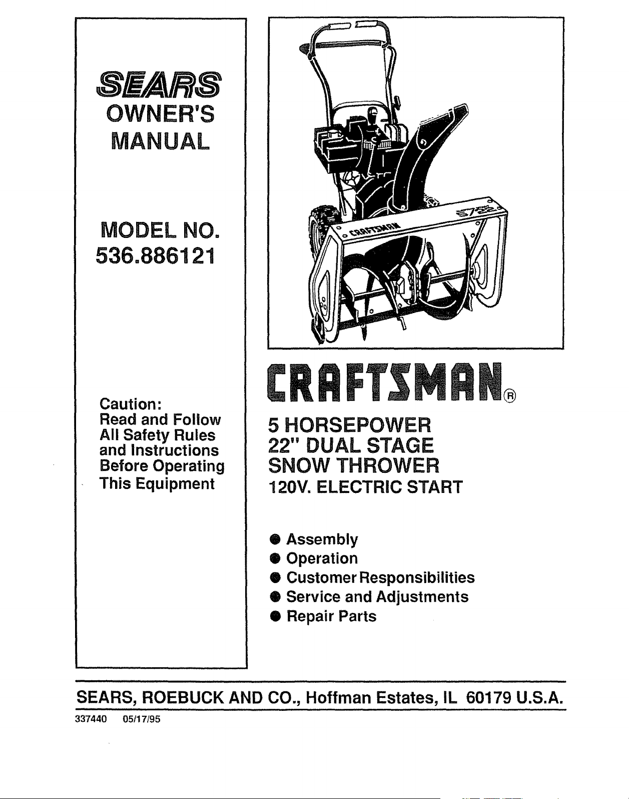
5 HORSEPOWER
22" DUAL STAGE
SNOW THROWER
120V. ELECTRIC START
• Assembly
• Operation
• Customer Responsibilities
• Service and Adjustments
Q Repair Parts
SEARS, ROEBUCK AND CO., Hoffman Estates, IL
337440 05/17/95
®
60179 U.S.A.
SAFETY RULES
CAUTION: ALWAYS DISCONNECT SPARK PLUG WIRE AND
PLACE WIRE WHERE IT CANNOT CONTACT SPARK PLUG
TO PREVENT ACCIDENTAL STARTING WHEN SETTING-UP,
TRANSPORTING, ADJUSTING OR MAKING REPAIRS.
IMPORTANT
SAFETY STANDARDS REQUIRE OPERATOR PRESENCE CONTROLS TO MINIMIZE THE
RISK OF INJURY. YOUR SNOW THROWER IS EQUIPPED WITH SUCH CONTROLS, DO NOT
ATTEMPT TO DEFEAT THE FUNCTION OF THE OPERATOR PRESENCE CONTROL UNDER
ANY CIRCUMSTANCES.
TRAINING 6,
1. Read the operator's manual carefully_ Be
thoroughly familiar with the controls and the 7,
proper use of the snow thrower. Know how to
stop the snow thrower and disengage the
controls quickly.
8-
2_ Never allow chUdren to operate the snow thrower
and keep them away while it is operating. Never
allow adults to operate the snow thrower without
proper instruction, Do not carry passengers., 9
3. Keep the area of operation clear of all persons,
particularly small children, and pets..
4. Exercise caution to avoid slipping or falling,
especially when operating in reverse
PREPARATION
1. Thoroughly inspect the area where the snow
thrower is to be used and remove all doormats,
sleds, boards, wires, and other foreign objects.
2. Disengage all clutches and shift into neutral
before starting the engine (motor).
3. Do not operate the snow thrower without wearing
adequate winter outer garments Wear footwear
that will improve footing on slippery surfaces.
4 Handle fuel with care; _tis highly flammable.
(a) Use an approved fuel container,
(b) Never remove fuel tank cap or add fuel to a
runningengineor hot engine°
(c) Fill fuel tank outdoors with extreme care
Never fill fuel tank indoors_
5_
(d) Replace fuel tank cap securely and wipe up
spilled fuel
(e) Never store fuel or snow thrower with fuel in
the tank inside of a building where fumes may
reach an open flame or spark.
(f) Check fuel supply before each use, allowing
space for expansion as the heat of the engine
(motor) and/or sun can cause fuel to expand.
Use extension cords and receptacles as specified
by the manufacturer for all snow throwers with
electric drive motors or electric starting motors.
Adjust the snow thrower height to clear gravel or
crushed rock surfaces.
Never attempt to make any adjustments while the
engine (motor) is running (except when
specifically recommended by the manufacturer)
Let engine (motor) and snow thrower adjust to
outdoor temperatures before starting to clear
snow,,
Always wear safety glasses or eye shieEds during
operation or while performing an adjustment or
repair to protect eyes from foreign objects that
may be thrown from the snow thrower-
OPERATION
1.. Do not put hands or feet near or under rotating
parts Keep clear of the discharge opening at all
times.
2. Exercise extreme caution when operating on or
crossing gravel drives, walks, or roads Stay alert
for hidden hazards or traffic.
3. After striking a foreign object, stop the engine
(motor), remove the wire from the spark plug,
disconnect the cord on electric motors,
thoroughly inspect the snow thrower for any
damage, and repair the damage before restarting
and operating the snow thrower.
zl_ If the snow thrower should start to vibrate
abnormally, stop the (motor) and check
immediately for the cause Vibration is generally
a warning of trouble..
5. Stop the engine (motor') whenever you leave the
operating position, before unclogging the auger/
impeller housing or discharge guide, and when
making any repairs, adjustments, or inspections
6 When cleaning, repairing, or inspecting, make
certain the augedimpeHer and all moving parts
have stopped. Disconnect the spark plug wire
and keep the wire away from the plug to prevent
accidental starting.
7. Take all possible precautions when leaving the
snow thrower unattended Disengage the auger/
impeller, shift to neutral, stop engine, and
remove key.
,l_lJIl_ II'l ......
SAFETY RULES
8. Do not tun the engine indoors, except when starting
the engine and for transporting the snow thrower in
or out of the building. Open the outside doors;
exhaust fumesare dangerous (containing CARBON
MONOXIDE, an ODORLESS and DEADLYGAS)
9° Do not clear snow across the face of slopes
Exercise caution when changing direction on
slopes_Do not attempt to clear steep slopes
10. Never operate the snow thrower without proper
guards, platesor other safety protectivedevices
in place.
11o Never operate the snow thrower near glass
enclosures, automobiles, window wells,
drop-otis, and the like without proper adjustment
of the snow discharge angle. Keep children and
pets away.
12. Do not overload the machine capacity by
attempting to clear snow at too fast a rater
13. Never operate the snow thrower at high transport
speeds on slippery surfaces. Look behind and
use care when backing
14 Never direct discharge at bystanders or allow
anyone in front of the snow thrower.
15. Disengage power to the auger/impeller when
snow thrower is transported or not in use..
16 Llse only attachments and accessories approved
by the manufacturer of the snow thrower (such
as tire chains, electric start kits, etc.),,
17_ Never operate the snow thrower without good
visibilityor light. Always be sure of your footing,
and keep a firm hold on the handles, Walk; never
run.
MAINTENANCE AND STORAGE
1. Check shear bolts and other bolts frequently for
proper tightness to be sure the snow thrower
is in safe working condition
2. Never store the snow thrower with fuel in the fuel
tank inside a building where ignition sources are
present such as hot water and space heaters,
clothes dryers, and the like,. Allow the engine to
cool before storing in any enclosure,
3o Always refer to operator's manual instructions
for important details if the snow thrower is to be
stored for an extended period
4 Maintain or replace safety and instruclion labels,
as necessary..
5. Run the snow thrower a few minutes after
throwing snow to prevent freeze-up of the auger/
impeller.
WARNING
This snow thrower Is for use on sidewalks,
driveways, and other ground level surfaces°
CAUTION should be exercised while using on
steep sloping surfaces. DO NOT USE SNOW
THROWER ON SURFACES ABOVE GROUND
LEVEL such as roofs of residences, garages,
porches or other such structures or buildings.
LOOK FOR THIS SYMBOL TO POINT OUT
IMPORTANT SAFETY PRECAUTIONS. IT
MEANS--ATTENTION!!! BECOME
ALERTI!! YOUR SAFETY IS INVOLVED.
......c=.0r,ia o s.io,,65WA""i.G!
_i The engine exhaust from this product
contains chemicals known to the State
of California to cause cancer, birth de-
fects or other reproductive harm.
3
CONGRATULATIONS on your purchase of a Sears
Craftsman Snow Thrower it has been designed, engi-
neered and manufactured to give youthe best possible
dependability and performance
Should you experience any problem you cannot easily
remedy, please contact your nearest Sears Service
CenterlDepartmenL Sears has competent, well-trained
technicians and the proper toolsto service or repairthis
unity
Please read and retain thismanual The instructions will
enable youto assemble andmaintainyoursnowthrower
properly. Always observe the "SAFETY RULES:
: RODUCT SPECIFICATIONS
llll i
HORSE POWER: 5 hp
DISPLACEMENT: 12.04
cu. in.
GASOLINE CAPACITY: 2 quarts
Unleaded
OIL (21 oz. Capacity): SAE 5W-30
SPARK PLUG : Champion
(GAP .030 in.) RJ19LM
VALVE CLEARANCE: Intake: .010 In.
Exhaust: .010 In.
MAINTENANCE AG REEMENT
A Sears Maintenance Agreement is available on this
product Contact your nearest Sears Store for details
CUSTOMER RESPONSIBILITIES
® Read and observe the safety rules
e Followa regular schedule in maintaining,caring for and using your snow thrower
e Followthe instructions under "Customer Responsibilities" and "Storage" sections of thisowner's manual
TWO YEAR LIMITED WARRANTY ON CRAFTSMAN
SNOW THROWER
For two years fromthe date of purchase, when this Craftsman Snow Thrower is maintained, lubricated
and tuned-up according to the instructions in the owner's manual, Sears will repair, free of charge, any
defect in material and workmanship_
If this Craftsman Snow Thrower is used for commercial or' rental purposes, this warranty applies for only
90 days from the date of purchase.
This warranty does not cover the following:
e Expendable items which become worn during normal use, such as spark plugs, drive belts and shear
pins.
o Repairs necessary because of operator abuse or negligence, including bent crankshafts and the failure
to maintain the equipment according to the instructions contained in the owner's manual
WARRANTY SERVICE IS AVAILABLE BY RETURNING THE CRAFTSMAN SNOW THROWER TO THE
NEAREST SEARS SERVICE CENTERIDEPARTMENT tN THE UNITED STATES THIS WARRANTY
APPLIES ONLY WHILE THIS PRODUCT IS IN USE IN THE UNITED STATES.
This warranty gives you specific legal rights, and you may also have other rights which may vary from
state to state_
SEARS, ROEBUCK AND CO Department DI817WA, Hoffman Estates, IL 60179
4
SA FEm_ RULES ........................................ 2_3
PRODUCT SPECIFICATIONS .......................... 4
CUSTOMER RESPONSIBILITIES .... 4,16-t8
WARRANTY ........................................................ 4
TABLE OF CONTENTS ............................................5
INDEX ......................................................................5
ASSEMBLY ..................................................... 6-9
OPERATION .......................................................10-t 5
SERVICE AND ADJUSTMENTS .............. I9-25
STO RAG E ..................................................... 26
TROUBLE SHOOTING ..............................................27
REPAIR PARTS (SNOW THROWER),,,. 28-39
REPAIR PARTS (ENGINE) ......................... 40-43
PARTS ORDERING/SERVICE ....................... 44
A
Adjustment:
Belt
Traction and Auger .......................20
Belt Guide ..................................................22
Cable .........................................................20
Carburetor ....................................................24
Frictbn Wheel ................................................22
Spark Plug .............................................25
Assembly:
Crank Assembly ..................................8
Shifter Lever Knob .............................9
Skid Height Adjustment ...............8, 19
Snow Chute ...........................................9
Unpacking .........................................................7
B
Bells:
Adjust Belts .............................................20
Belt Guide Adjustment ..........................22
Replace Belts ...........................................21
C
Cables, Clutch ..............................7, 9, 20
Carburetor: ...................................................24
Choke ................................10, 11, t4,15
Clutch, Levers .............................7, 9,10, 12
Controls:
Engine ......................... 10, 11, 14, 15
Snow Thrower ........................10, 11,12
Crank:
Assembly ...............................................8
Operation ................................................11
Customer Responsibilities ..........4,16-18
Agreement .............................................4
Auger Gear Box ........................................18
Auger Shaft ............................................17
Engine....................................................i8
General Recommendations ................16
Hex Shaft and Gears .........................18
D
Drive, Auger ..................................................12
Drive, Traction ..........................................12
Deflector, Snow Chute ...........................11
E
Engine:
Control ..................................10, tl, 14, 15
Oil Cap .........................................13, 18
OilChange ...................................................18
OilLevel ......................................13, 18
OU Type ..................................4, 13, 18
Speed Governor .....................................24
Starting, Electrically...............................14
Starting, Manually ......................14, 15
Storage ...................................................26
INDEX
F
Fuel, Type ....................................4, 13, 18
Fuel, Storage .......................................t3, 28
Friction Wheel:
Adjustmen!..................................................22
Replacement ................................... 23
G
Gears:
Auger Gear Box .......................................18
He× Shaft ................................................18
H
Handle, Upper and Lower .................7, 8
Height Adjust Skids ...............................8, 19
Hex Shaft ...................................................18
I
Ignition, Key .......................I0, 11, !4, 15
Index.....................................................5
L
Levers:
Auger Drive Clutch .................................
.... ....................................7, 9, 10, 11, t2, 20
Choke .........................10, 11, 13, !4, 15
Shitter .............................................9, 10, 12
Throttle Control ..............I 0, 11, 14, 15
Traction Drive Clutch ...............................
..........................................7, 9, 10, 11,12, 20
Lubrication:
Auger Gear Box .........................................18
Auger Shaft .............................................17
Axles ......................................................17
Chart .............................................................16
Dfsc Drive Plate ........................................17
Engine ....................................13,18,26
Hex Shaft and Gears ...........................18
O
Oil:
Engine ........................................4, !3, 18
Extreme Cold Weather ...............13,18
Storage .....................................................26
Type ......................................................4, 13, 18
Operation:
Engine Controls ............. 10, 11, 14,15
Operating Snow Thrower., 11, 12, 15
Lockout Pin, Wheel ............................12
Operating Tips ........................................15
Startingthe Engine, Electric .............14
Starting the Engine, Recoil ................15
Snow Thrower Controls ...............10-12
P
Parts ..............................................................28-43
Primer Button .....................10, 11, 14,15
R
RepairtReplacement Parts .......... 28-43
Recoil Starter ......................................14
Replacements:
Auger Shear Bolt .............................24
Belts ......................................... 20,21
Friction Wheel .................... 22,23
S
Safety Rules ......................................2, 3
Service and Adjustments:
Auger Housing Height .............. 7, !8
Auger Shear Boft ........................ 23
Belts ........................................... 20-21
Bell Guide ..................................... 22
Belt Replacements .................... 20
Cable ................................. 7, 9, 20
Carburetor .......................... 13,24, 26
Friction Wheel ..................... 22, 23
Scraper Bar .............................. t9
Spark Plug .............................. 25
Spark Plug .............................. t8, 25
Specifications ................................. 4
Speed Governor ........................... 24
Starting the Engine:
Recoil Start ........................ 14, t5
Electric Start ................................... t 4
Stopping the Engine ................. 14
Stopping the Snow Thrower ............ 11
Shipping Carton ...................................6, 7
Skid Height ......................................8, 19
Shifter Lever ................................ 9,12
Shear Bolts ....................................... 24
Storage ........................................... 26
T
Table of Contents ............................. 5
Trouble Shooting Chart ................... 27
Tools for Assembly .......................... 6
Traction Drive Belt .............. 20, 2t
Tire Pressure ................... 13,19
W
Warranty ............................................. 4
Wheel, Lockout Pin ...................... 12
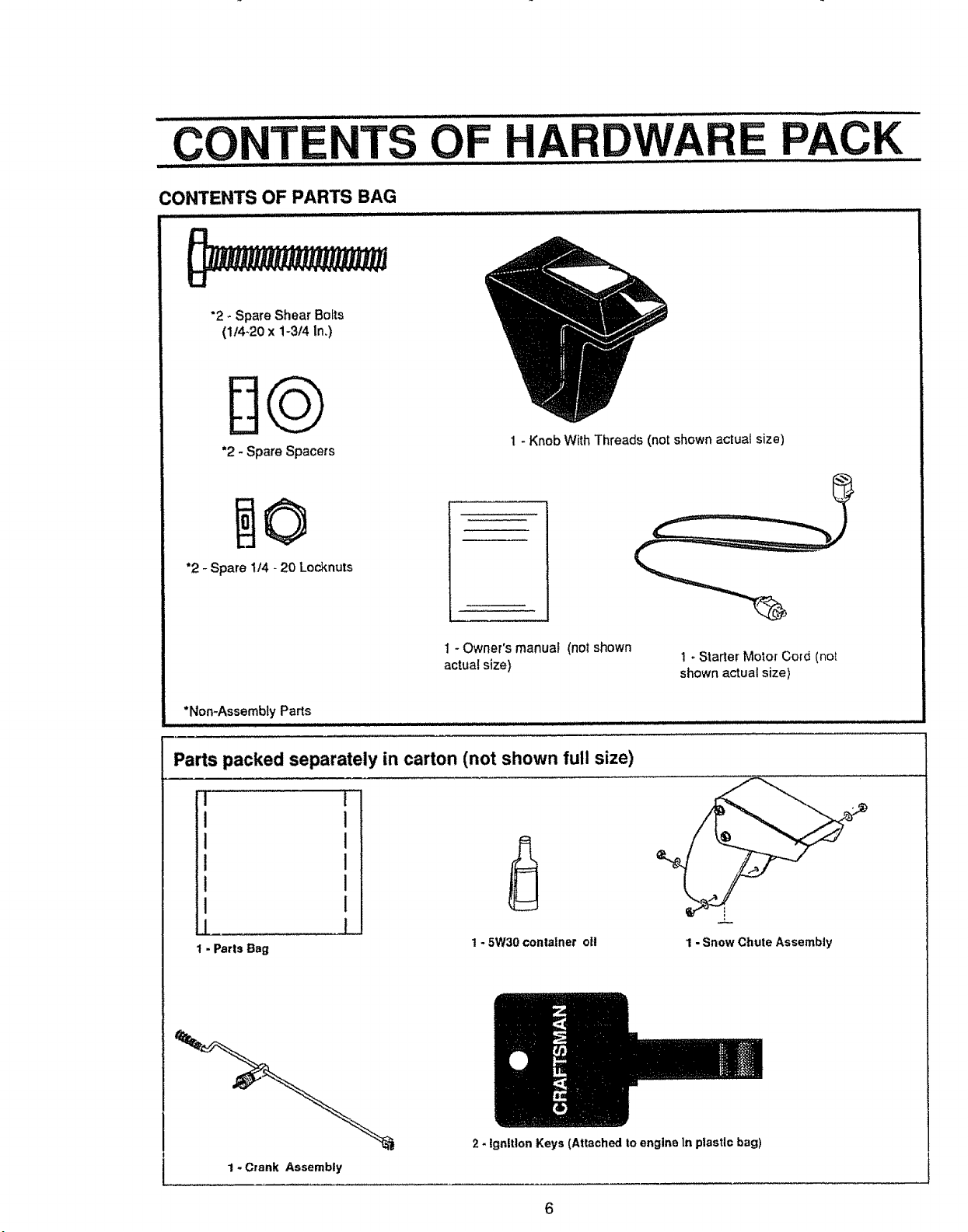
CONTENTS OF
HARDWARE PACK
CONTENTS OF PARTS BAG
................................. ,,,,, ,,,,,,,,,,,,,,,,,,
"2 - Spare Shear Bolts
(1/4.20 x 1-3/4 In.)
DQ
*2 - Spare Spacers
1 - Knob With Threads (not shown actual size)
"2 - Spare 1t4 - 20 Locknuts
1 - Owner's manual (not shown
actual size)
*Non-Assembly Parts
Parts packed separately in carton (not shown full size)
1 - Starter Molor Cord (not
shown actual size)
I
I
I
i
I
1 - Parts Bag
1 - 5W30 container oft
='_L
1 - Snow Chute Assembly
1 - Crank Assembly
2 - Ignition Keys (Attached to engine In ptastlc bag)
6
H ,,,,,i ,,i IIIIH,.I. II.I I I ,I Illll II I ,/'/ I,,,,,,, .....
AS LY
TOOLS REQUIRED FOR ASSEMBLY ......................................................
1 - Knife (to cut carton and plastic ties)
2 - !12 inch wrenches (or adjustable wrenches)
2 - 9116 inch wrenches (or adjustable wrenches)
2 - 3/4 inch wrenches (or adjustable wrenches)
t - Pliers (to spread cotter pin)
I- Screwdriver
1 - Measuring Tape or Ruler
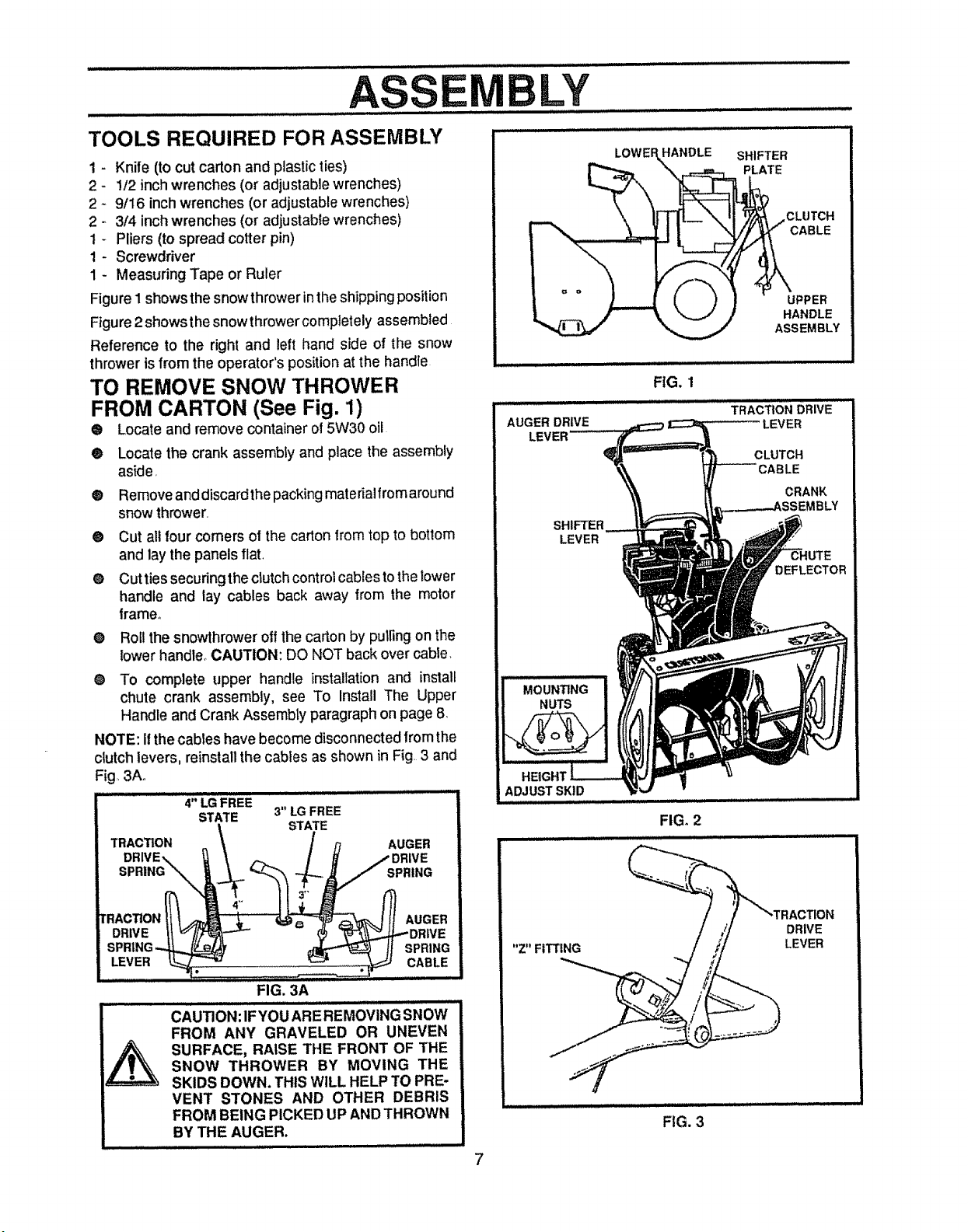
Figure 1 shows the snowthrower in the shipping position
Figure 2showsthe snowthrowercomptetely assembled
Reference to the right and left hand side of the snow
thrower is from the operator's position at the handle
TO REMOVE SNOW THROWER
FROM CARTON (See Fig. 1)
® Locate and remove container of 5W30 oil
• Locate the crank assembly and place the assembly
as{de,
O
O
® Remove and discardthe packing materialfrom around
snow thrower,
® Cut all four comers of the carton from top to bottom
and lay the panels flat.
e Cut ties securing the clutch control cables to the lower
handle and lay cables back away from the motor
frame°
Roll the snowthrower off the carton by puli_ngon the
lower handle_CAUTION: DO NOT back over cable.
To complete upper handle installationand install
chute crank assembly, see To Install The Upper
Handle and Crank Assembly paragraph on page 8
NOTE: Itthe cables have become disconnected from the
clutch levers, reinstall the cables as shown in Fig, 3 and
Fig, 3Ao
i i ill iqt ii mE HqLI II
........... 4" LG FREE
STATE 3" LG FREE
STATE
TRACTION __ AUGER
DRIVE.,.. / DRIVE
SPRING_\.. J SPRING
tRACTION_"__ _--"_ f_ AUGER
DRIVE _1_"//,, _,_DRIVE
SPR|NG-.._ _ H SPRING
LEVER 1___2 ......i,;,,'i,,,i,,ii'i,i,_ CABLE,
FIG. 3A
CAU]ION :IF YOUARE REMOVING SNOW
FROM ANY GRAVELED OR UNEVEN
SURFACE, RAISE THE FRONT OF THE
SNOW THROWER BY MOVING THE
SKIDS DOWN. THIS WiLL HELP TO PRE-
VENT STONES AND OTHER DEBRIS
FROM BEING PICKED UP AND THROWN
BY THE AUGER.
LOWE HANDLE
SHIFTER
PLATE
UPPER
HANDLE
ASSEMBLY
FIG. 1
ADJUST SKID
FIG. 2
DRIVE
LEVER
FIG. 3
7
LY
HOW TO SET UP YOUR SNOW
THROWER
® Your snow thrower is equipped with height adjust
skids (See Fig_ 2) on the outside of the auger
housing. To adjust the skid height for different
conditions, see To Adjust Skid Height paragraph or]
page 19.
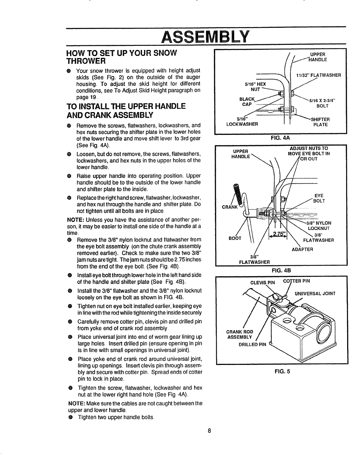
TO INSTALL THE UPPER HANDLE
AND CRANK ASSEMBLY
® Remove the screws, flatwashers, lockwashers, and
hex nuts securing the shifter plate in the lower holes
of the lower handle and move shift lever to 3rd gear
(See Fig. 4A)_
@ Loosen, but do not remove, the screws, flatwashers,
tockwashers,and hex nuts in the upper' holes of the
lower handle.
® Raise upper handle into operating position. Upper
handle should be to tile outside of the lower handle
and shifter plate to the inside.,
® Replace the right hand screw,flatwasher, Iockwasher,
and hex nut through the handle and shifter plate,.Do
not tighten until all bolts are in place
NOTE: Unless you have the assistance of another per-
son, it may be easier to installone side of the handle at a
time.
® Remove the 3/8" nylon Iocknut and flatwasher from
the eye bolt assembly (on the chute crank assembly
removed eadier). Check to make sure the two 3t8"
jam nuts are tight., The jam nuts should be 2.75 inches
from the end of the eye bolt. (See Fig. 4B).
® Install eye bolt through lower hole inthe left hand side
of the handle and shifter plate (See Fig. 4B).
e Install the 3!8" flatwasher and the 3t8" nylon Iocknut
looselyon the eye bolt as shown in FIG 4B.
® Tighten nut on eye bolt installedearlier, keeping eye
in line with the rod while tightening the inside securely
® Carefully remove cotterpin, clevis pin and drilled pin
from yoke end of crank rod assembly.
® Place universal joint into end of worm gear lining up
large holes. Insert drilled pin (ensure opening in pin
is in line with small openings in universal joint).
® Place yoke end of crank rod around universal joint,
lining up openings, Insert clevis pin throughassem-
bly and secure with cotter pin.. Spread ends of cotter
pin to lock in place..
• Tighten the screw, flatwasher, !ockwasher and hex
nut at the lower right hand hole (See Fig 4A).
NOTE: Make sure the cables are not caught between the
upper and lower handle,
® Tighten two upper handle boils.
UPPER
)LE
11t32" FLATWASHER
NUT
BLACK 2.3_ ,_
CAP BOLT
5/16" HIFTER
LOCKWASHER PLATE
FIG, 4A
ADJUSTNUTSTO
UPPER
HANDLE_,_ MOVE EYE BOLTIN
OUT
EYE
3/8"
FLAW='ASHER
LOCKNUT
FLATWASHER
ADAPTER
FIG. 4B
CLEVIS PiN 'ER PIN
UNIIVERSALJO]NT
CRANK ROD
ASSEMBLY
DRILLED PIN
FIG. 5
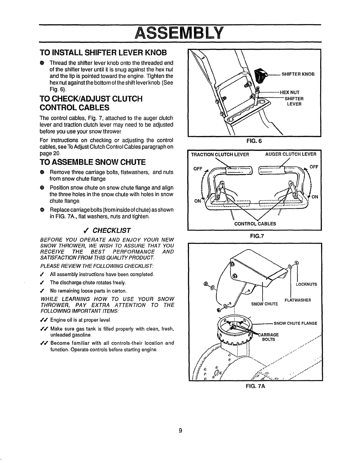
TO iNSTALL SHIFTER LEVER KNOB
@ Thread the shifter lever knob onto the threaded end
of the shifter lever until it is snug against the hex nut
and the lip is pointed toward the engine. Tighten the
hex nut against the bottom o! the shift lever knob (See
Fig. 6).,
TO CHECK/ADJUST CLUTCH
CONTROL CABLES
The control cables, Fig_7, attached to the auger clutch
lever and traction clutch lever may need to be adjusted
before you use your snow thrower.
For instructionson checking or adjusting the control
cables, see ToAdjust Clutch Control Cables paragraph on
page 20.
TO ASSEMBLE SNOW CHUTE
• Remove three carriage bolts, flatwashers, and nuts
from snow chuteflange.
e Position snow chute on snow chute flange and align
the three holes inthe snow chute with holes insnow
chute flange.
e Replace carriage bolts (from inside of chute) asshown
in FIGo7A. flat washers, nuts and tighten..
_/ CHECKLIST
BEFORE YOU OPERATE AND ENJOY YOUR NEW
SNOW THROWER, WE WISH TO ASSURE THAT YOU
RECEIVE THE BEST PERFORMANCE AND
SATISFACTION FROM THIS QUALITY PRODUCT.
PLEASE REVIEW THE FOLLOWING CHECKLIST:
#' All assembly instructionshave been completed.
4' The discharge chute rotates freely.
/ No remaining !oose parts in carton_.
WHILE LEARNING HOW TO USE YOUR SNOW
THROWER, PAY EXTRA ATTENTION TO THE
FOLLOWING IMPORTANT ITEMS:
/./' Engine oil is at proper level.
i'v" Make sure gas tank is filied properly with clean, fresh,
unleaded gasoline.
/,/' Become familiar with all controls-their location and
function. Operate controts before starting engine.
LEVER
FIG. 6
T.A'c:noNcLuTC.L E. Au E"CLuTc,LEVER
CONTROL CABLES
FIG.7
LOCKNUTS
FLA'TWASHER
SNOW CHUTE
_,GE
BOLTS
FLANGE
FIG. 7A
9
......... i ii iillllIll I I,,11I, ul Ill I ll,,I.
O T
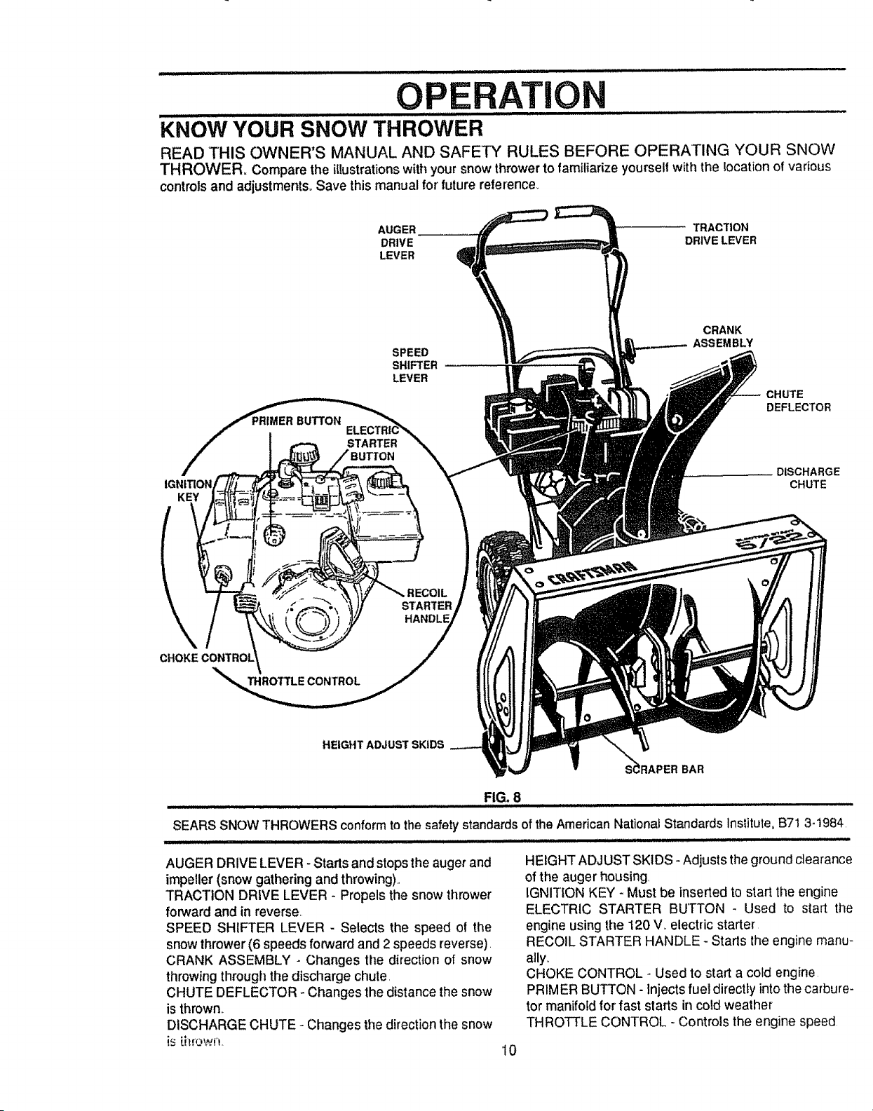
KNOW YOUR SNOW THROWER
READ THIS OWNER'S MANUAL AND SAFETY RULES BEFORE OPERATING YOUR SNOW
THROWER= Compare the illustrationswithyour snow thrower to familiarize yourselfwith the location of various
controlsand adjustment& Save this manual for future reference.
AUGER TRACTION
DRIVE DRIVE LEVER
LEVER
KEY
BUTTON
STARTER
SPEED
SHIFTER
LEVER
CRANK
ASSEMBLY
CHUTE
DEFLECTOR
DISCHARGE
CHUTE
\
STARTER
HANDLE
THROTTLE CONTROL
HEIGHT ADJUST SKIDS
S_RAPER BAR
FIG. 8
SEARS SNOW THROWERS conformto the safety standards of the American National Standards Institute, B71 3-1984
........................ . ..... ,,,, , ,,,,,,,,, , ,,,,
AUGER DRIVE LEVER - Starts and stops the auger and
impeller (snow gathering and throwing).,
TRACTION DRIVE LEVER - Propels the snow thrower
forward and in reverse,
SPEED SHIFTER LEVER - Selects the speed of the
snow thrower (6 speeds forward and 2 speeds reverse).
CRANK ASSEMBLY - Changes the direction of snow
throwing through the discharge chute.
CHUTE DEFLECTOR - Changes the distance the snow
is thrown,,
DISCHARGE CHUTE - Changes the direction the snow
is _itrown.
10
HEIGHT ADJUST SKIDS - Adjusts the ground clearance
of the auger housing,
IGNITION KEY - Must be inserted to start the engine
ELECTRIC STARTER BUTTON - Used to start the
engine using the 120 V,. electric starter
RECOIL STARTER HANDLE - Stads the engine manu-
ally,.
CHOKE CONTROL - Used to start a cold engine
PRIMER BUTTON - Injects fuel directty into the carbure-
tor manifofd for fast starts in cold weather
THROTTLE CONTROL - Controls the engine speed
OPE
TION
The operation of any snow thrower can result in foreign objects being thrown into the
eyes, which can result in severe eye damage. Always wear safety glasses or eye
shields while operating the snow thrower.
We recommend standard safety glasses available at SEARS Retail Stores or
Service Centers
u
These symbols may appear on your unit° Learn and understand their meaning.
ENGINE
START
ENGINE OFF CHOKE FAST SLOW
RUN OFF
STOP FUEL
OIL PRIMER
BUTTON
TRACTION
DRIVE
CLUTCH
AUGER
DRIVE
CLUTCH
IGNI_ON KEY
INSERTTO
RUN PULL OUT
TO STOP
CAUTION: READ OWNER'S MANUAL BE-
FORE OPERATING MACHINE, NEVER
DIRECT DISCHARGE TOWARD BY-
STANDERS. STOP THE ENGINE BEFORE
UNCLOGGING DISCHARGE CHUTE OR
AUGER HOUSING AND BEFORE LEAV-
ING _'HE MACHINE.
HOW TO USE YOU R SNOW
THROWER
TO STOP YOUR SNOW THROWER
• To stopthrowing snow, release the augerdrive lever
(See Fig. 11, page 12)..
® To stop the traction drive, release the traction drive
lever. (See Figure ! 1, page ! 2),.
® To stop the engine, push the throttle control lever to
STOP and pull out the ignition key (See Fig. 10).
NOTE: DO NOT turn key..
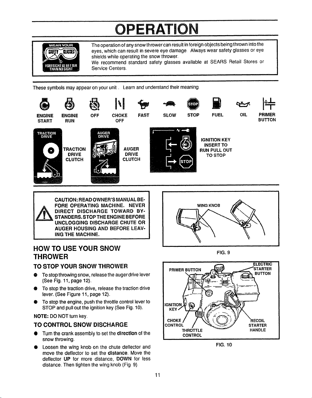
TO CONTROL SNOW DISCHARGE
O
O
Turn the crank assembly to set the direction of the
snow throwing,
Loosen the wing knob on the chute deflector and
move the deflector to set the distance,, Move the
deflector UP for more distance, DOWN for less
distance. Then tighten the wing knob (Fig 9)
11
WING KNOB
FIG. 9
THROTTLE
CONTROL
FIG. 10
STARTER
HANDLE
/1111 i IIH,
O
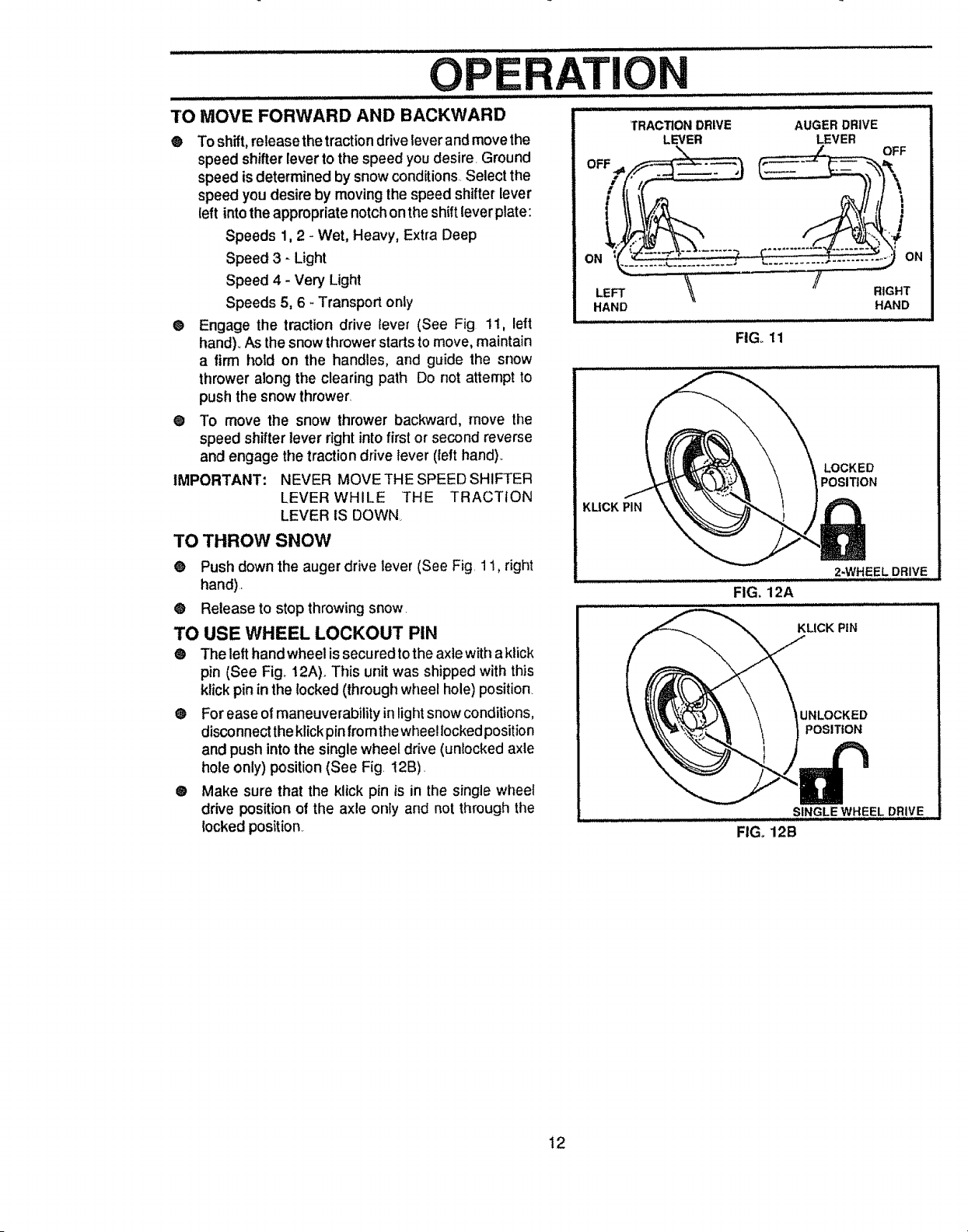
TO MOVE FORWARD AND BACKWARD
@ To shift, re]easethe tractiondrive lever andmovethe
speed shifter lever to the speed youdesire, Ground
speed is determined by snow conditions,,Select the
speed you desire by movingthe speed shifter lever
(eft intothe appropriatenotchonthe shiftlever plate:
Speeds 1, 2 - Wet, Heavy, Extra Deep
Speed 3 - Light
Speed 4 - Very Light
Speeds 5, 6 _Transportonly
• Engage the traction drive lever (See Fig 11, left
hand)_As the snow thrower starts to move, maintain
a firm hold on the handles, and guide the snow
thrower along the clearing path Do not attempt to
push the snow thrower.
@ To move the snow thrower backward, move the
speed shifter lever right into first or second reverse
and engage the traction drive lever (left hand).,
IMPORTANT: NEVER MOVE THE SPEED SHIFTER
LEVER WHILE THE TRACTION
LEVER IS DOWN
TO THROW SNOW
@ Push down the auger drive lever (See Fig. 11, right
hand)
@ Release to stop throwing snow.
TO USE WHEEL LOCKOUT PIN
® The left hand wheel is secured to the axle with aklick
pin (See Fig_ !2A). This unit was shipped with this
klick pin in the locked (through wheel hole) position_
Q For ease of maneuverability in light snow conditions,
disconnect the klick pin from the wheel locked position
and push into the single wheel drive (unlocked axle
hole only) position (See Fig. t2B).
® Make sure that the klick pin is in the single wheel
drive position of the axle only and not through the
locked position
ATION
TRACTION DRIVE
LEVER
AUGER DRIVE
LEVER
\
HAND
FIGo 11
KUCK PIN
/ RIGHT
HAND
LOCKED
POSITION
2-WHEEL DRIVE
FIG, 12A
KLICK PiN
UNLOCKED
POSITION
SINGLE WHEEL DRIVE
FIG. 12B
12
i ,,, ,,,,,,,,,,,,,,,,,, ..................................................................
OP T
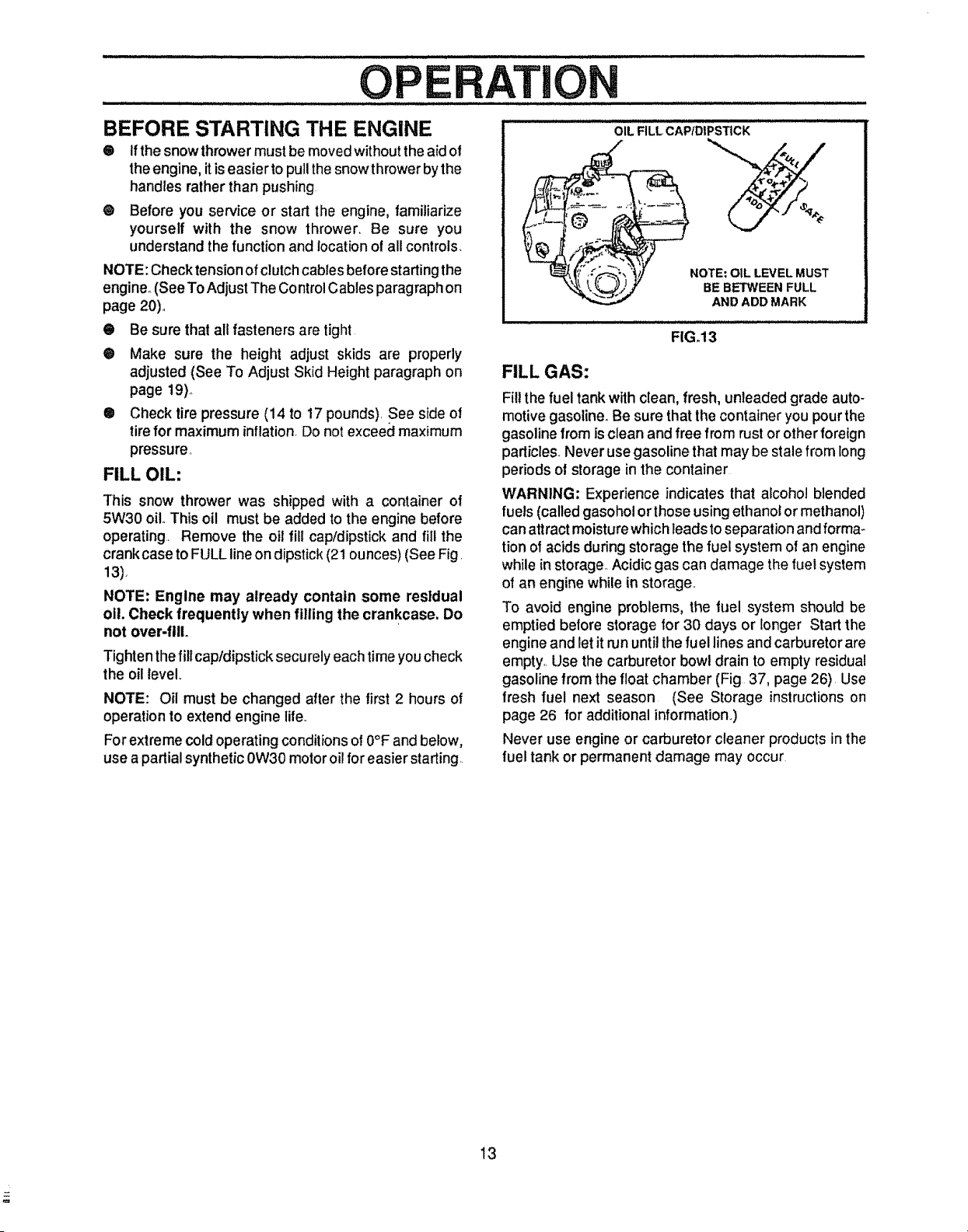
OIL FILL CAP/DIPSTICKBEFORE STARTING THE ENGINE
® If the snowthrowermustbe moved withoutthe aid of
the engine, itis easier to pullthe snow throwerbythe
handles rather than pushing
O Before you service or start the engine, familiarize
yourself with the snow thrower Be sure you
understand the function and locatfonof all controls.
NOTE: Check tension of clutch cables before starting the
engine_(See To Adjust The Control Cables paragraph on
page 20).
• Be sure that all fasteners are tight
® Make sure the height adjust skids are properly
adjusted (See To Adjust Skid Height paragraph on
page 19)o
® Check tire pressure (14 to 17 pounds) See side of
tire for maximum inflation Do not exceed maximum
pressure
FILL OIL:
This snow thrower was shipped with a container of
5W30 oil. This oil must be added to the engine before
operating Remove the oil fill cap/dipstick and fill the
crankcase to FULL line on dipstick (2t ounces) (See Fig
13).
NOTE: Engine may already contain some residual
oil. Check frequently when filling the crankcase, Do
not over-filL
Tighten the fill cap/dipstick securely each time you check
the oil level
NOTE: Oil must be changed after the first 2 hours of
operation to extend engine life.
For extreme cold operating conditions o! 0°F and below,
use apartial synthetic 0W30 motor oil for easier starting
NOTE: OIL LEVEL MUST
BE BETWEEN FULL
AND ADD MARK
FILL GAS:
FIG_13
Fill the fuel tank with clean, fresh, unleaded grade auto-
motive gasoline° Be sure that the container you pour the
gasoline from is clean and free from rust or other foreign
particles. Never use gasoline that may be stale from long
periods of storage in the container
WARNING; Experience indicates that alcohol blended
fuels (called gasohol orthose using ethanol or methanol)
can attract moisture which leads to separation and forma-
tion of acids during storage the fuel system of an engine
while in storage_ Acidic gas can damage the fuel system
of an engine while in storage°
To avoid engine problems, the fuel system should be
emptied before storage for 30 days or longer Start the
engine and let it run until the fuel lines and carburetor are
empty. Use the carburetor bowl drain to empty residual
gasoline from the float chamber (Fig 37, page 26) Use
fresh fuel next season (See Storage instructionson
page 26 for additional information,,)
Never use engine or carburetor cleaner products in the
fuel tank or permanent damage may occur
13
TO STOP ENGINE
® To stop engine, move the throttle control lever to
STOP positionand remove key Keep the key in a
safe place_The enginewiltnotstartwithoutthe key_
TO START ENGINE (Electric Starter)
Be sure that the engine has sufficientoil. The snow
throwerengine is equippedwith a 120 voltA C_ electric
starter and recoil starter, Before starting the engine, be
certain that you have read the following information:
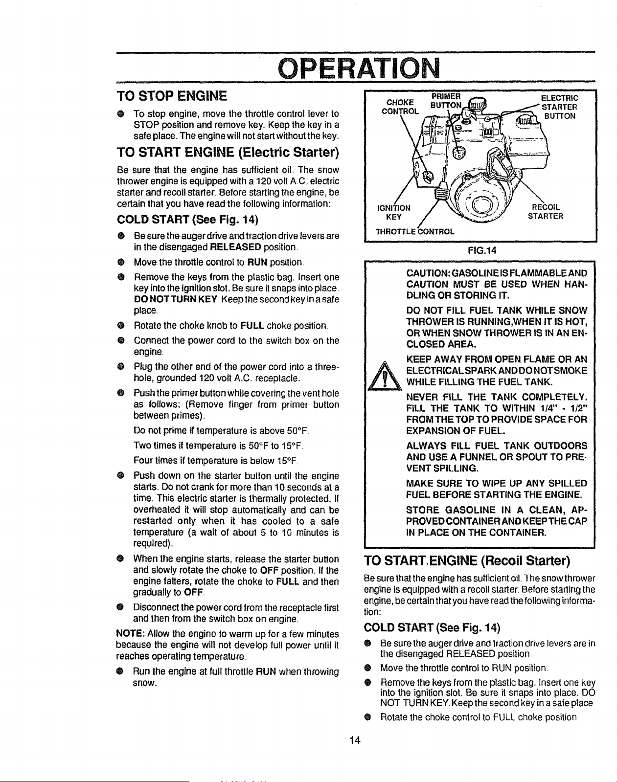
COLD START (See Fig. 14)
® Be sure the auger drive and traction drive leversare
in the disengaged RELEASED position.
e Move the throttle controlto RUN position
® Remove the keys from the plastic bag, Insert one
key into the ignition slot. Be sure it snaps into place
DO NOTTURN KEY..Keep the second key in a safe
place,
@ Rotate the choke knob to FULL choke position.
® Connect the power cord to the switch box on the
engine.
® Plug the other end of the power cord into a three-
hole, grounded 120 volt A_C..receptacle.
® Push the primer button while covering the vent hole
as follows: (Remove finger from primer button
between primes).
Do not prime if temperature is above 50°F.
Two times if temperature is 50°F to 15°F.
Four times if temperature is below 15°F.
® Push down on the starter button until the engine
starts.. Do not crank for more than 10 seconds at a
time, This electric starter is thermally protected_If
overheated it will stop automatically and can be
restarted only when it has cooled to a safe
temperature (a wait of about 5 to 10 minutes is
required).
® When the engine starts, release the starter button
and slowly rotate the choke to OFF position. If the
engine falters, rotate the choke to FULL and then
gradually to OFF.
® Disconnect the powercord from the receptacle first
and then from the switch box on engine.
NOTE: Allow the engine to warm up for a few minutes
because the engine will not develop full power until it
reaches operating temperature.
® Run the engine at full throttle RUN when throwing
snow.
PRIMER ELECTRIC
CHOKE BU'FI'ON rER
CONTROL
,_ BUTTON
/
IGNITION RECOIL
KEY STARTER
FIG,14
CAUTION: GASOLINE IS FLAMMABLE AND
CAUTION MUST BE USED WHEN HAN-
DLING OR STORING IT.
DO NOT FILL FUEL TANK WHILE SNOW
THROWER IS RUNNING,WHEN IT IS HOT,
OR WHEN SNOW THROWER IS IN AN EN-
CLOSED AREA.
KEEP AWAY FROM OPEN FLAME OR AN
ELECTRICAL SPARK AND DO NOT SMOKE
WHILE FILLING THE FUEL TANK.
NEVER FILL THE TANK COMPLETELY.
FILL THE TANK TO WITHIN 114" - 1t2"
FROM THE TOP TO PROVIDE SPACE FOR
EXPANSION OF FUEL.
ALWAYS FILL FUEL TANK OUTDOORS
AND USE A FUNNEL OR SPOUT TO PRE-
VENT SPILLING.
MAKE SURE TO WIPE UP ANY SPILLED
FUEL BEFORE STARTING THE ENGINE,
STORE GASOLINE IN A CLEAN, AP-
PROVED CONTAINER AND KEEP THE CAP
IN PLACE ON THE CONTAINER_
TO STARTENGINE (Recoil Starter)
Be sure thatthe engine has sufficient oil.The snow thrower
engine is equipped with a recoit starter, Before starting the
engine, be certain that you have read the foUowinginfor ma-
rion:
COLD START (See Fig. 14)
® Be sure the augerdfive and tractiondrive levers are in
the disengaged RELEASED position.
® Move the throttle controlto RUN position.
® Remove the keys from the plasticbag., Insert one key
into the ignitionslot. Be sure it snaps into place. DO
NOT TURN KEY Keep the second key in asafe place
® Rotate the choke control to FULL choke position
t4
' OPE ...................................AT
CAUTION: NEVER RUN ENGINE
INDOORS OR IN ENCLOSED, POORLY
VENTILATED AREAS°ENGINE EXHAUST
CONTAINS CARBON MONOXIDE, AN
ODORLESS AND DEADLY GAS. KEEP
HANDS, FEET, HAIR AND LOOSE
CLOTHING AWAY FROM ANY MOVING
PARTS ON ENGINE AND SNOW
THROWER.
WARNING: TEMPERATURE OF
MUFFLER AND NEARBY AREAS MAY
EXCEED 150° F. AVOID THESE AREAS.
DO NOT ALLOW CHILDREN OR YOUNG
TEENAGERS TO OPERATE OR BE NEAR
SNOW THROWER WHILE IT IS
OPERATING.
CAUTION: DO NOT ATTEMPT TO RE-
MOVE ANY ITEM THAT MAY BECOME
LODGED IN AUGER WITHOUT TAKING
THE FOLLOWING PRECAUTIONS:
RELEASE AUGER DRIVE AND TRACTION
DRIVE LEVERS,,
- MOVETHROTTLELEVERTOSTOP PO-
SITION.
o REMOVE (DO NOT TURN) IGNITION
KEY.
o DISCONNECT SPARK PLUG WIRE,
• DO NOT PLACE YOUR HANDS IN THE
AUGER OR DISCHARGE CHUTE. USE
A PRY BAR.
O
Push the primer button while covering the vent hole
as follows: (Remove finger from primer button be-
tween primes)_
Do not prime if temperature is above 50°E
Two times if temperature is 50°F to 15°F
Four times if temperature is below 15°F.
® Pull the recoil starter handle rapidly. Do not allow the
handleto snap back, but allow itto rewind slowlywhile
keeping a firm hold on the starter handle.
• As the engine warms up and begins to operate
evenly, rotate the choke control slowly to the OFF
position,. If the engine falters, return to FULL choke,
then slowly move to the OFF position.
NOTE: Allow the engine to warm up for a few minutes
because the engine will not develop full power until it
reaches operatingtemperature,
• Run the engine at full throttle (RUN) when throwing
snow°
WARM START
If restarting a warm engine after a short shutdown, leave
choke at OFF and do not push the primer button. If the
engine fails to start, follow the Cold Start instructions
above.
FROZEN STARTER
tf the starter is frozen and will not turn engine:
O Pull as much rope out of the starter as possible
• Release the starter handle and let it snap back
against the starter
Ifthe engine still fails to start, push the primer button two
or three times again and repeat the two previous steps
until the engine starts. Then continue with the directions
for cold slart.
To heip prevent possible freeze-up of recoil starter and
engine controls, proceed as follows after each snow
removal job
e With the engine running, pull the starter rope hard
with a continuous full arm stroke three or four times.
Pullingof starter rope will produce a loud clattering
sound This is not harmlul to the engine or starter.
e With the engine not running, wipe all snow and
moisture fromthe carburetor cover in area of control
levers. Also move throttle control, choke control, and
starter handte several times
SNOW THROWING TIPS
e For maximum snow thrower efficiency in removing
snow, adjust ground speed, NEVER the throttle.. Go
slower in deep, freezing, or wet snow. tf the track
slips, reduce forward speed, The engine is designed
to deliver maximum pedormance at full throttle and
should be run at this power setting at all times
e Most efficient snow throwing is accomplished when
the snow is removed immediately after it falls.
® For complete snow removal, slightly overlap each
path previously taken.
e The snow should be discharged down wind whenever
possible_
@ For normal usage, set the skids so that the scraper
bar is 1/8" above the skids. For extremely hardpacked
snow surfaces, adjust the skids upward so that the
scraper bar touches the ground.
O On gravel orcrushed rock sudaces, set the skids at
1-1/4" below the scraper bar (see To Adjust Skid
Height paragraph on page 19). Stones and gravel
must not be picked up and thrown by the machine
• After the snow throwing job has been completed,
allow the engine to idle for a few minutes, whichwill
melt snow and accumulated ice off the engine
• Clean the snow thrower thoroughlyafter each use
I, Remove ice and snow accumufation and all debris
from the entire snow thrower, and flush with warer (if
possible) to remove all salt or other chemicals Wipe
snow thrower dry.
15
CUSTOM ILITI
J .,,,,,,,,
SERVICE RECORDS
,,,uL.... ,,J, ..................
SCHEDULE
Fill in dates as you complete
regular service After Before As
First 2 Each Needed
hours Use
Every I Every Every Each Before
5 10 25 Season Storage
Hours Hours Hours
SERVICE
DATES
Check Engine Oil Level _ pJ
Change Engine Oil _
- = =
Tighten Al! Screws and Nuts PJ .............. PJ I ......
Lub,=teA,Pi,otPoint, V" _'
, , ,......... , ,,,,,.......
Lubricate Auger Shaft (See Shear
Bolt Replacement) _ PJ
Lubricate Disc Drive Plate Zerk (See
Customer Responsibilities) PJ PJ
J
,,,,, ,,,
i Check Auger Clutch Cable
Adjustment (See Cable Adjustment) PJ
Check Traction ciUtch Cable ' i
Adjustment (See Cable Adjustment) _
AdjustD,iveSe,_ _" 11 I,"
Check Fuel
Drain Fuel
Replace Spark Ptug
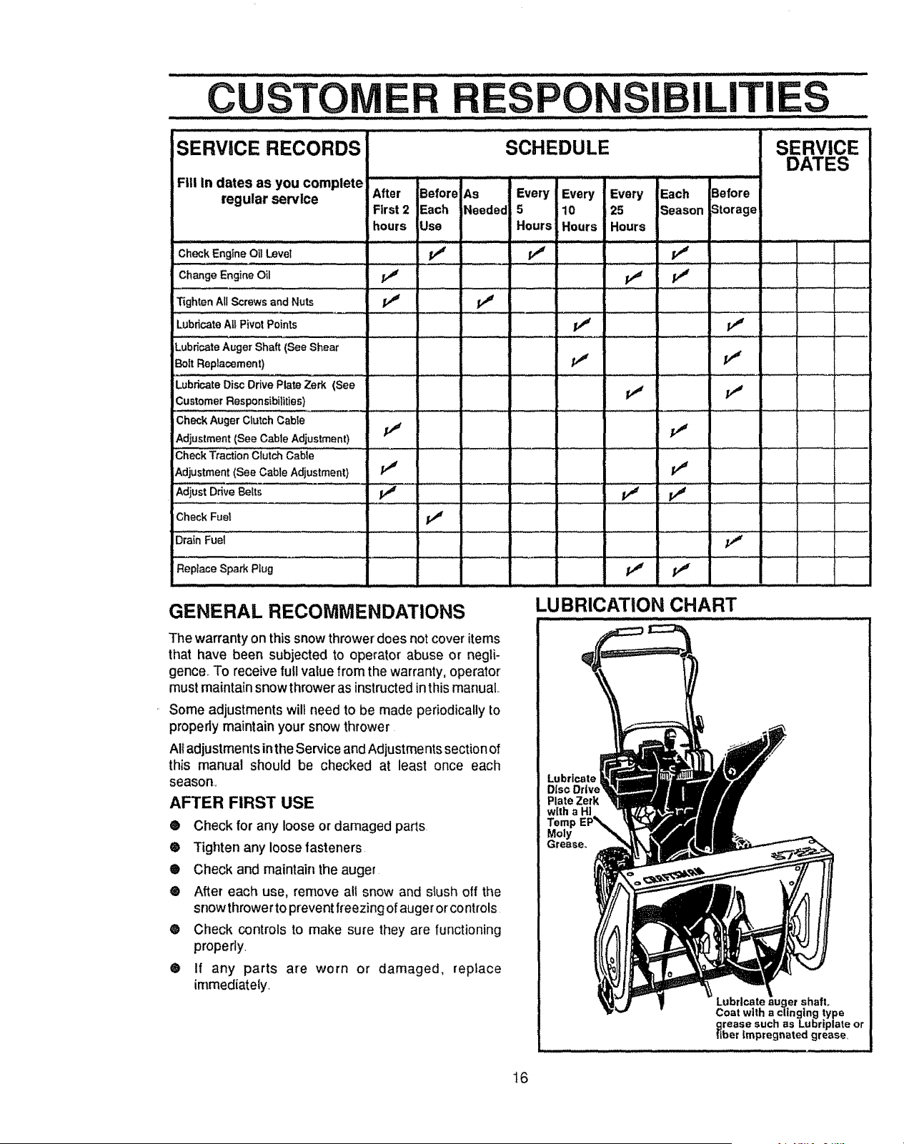
GENERAL RECOMMENDATIONS
The warranty on thissnowthrower does not cover items
that have been subjected to operator' abuse or negli-
gence, To receive full value from the warranty, operator
must maintain snow thrower as instructed in thismanuat..
Some adjustments will need to be made periodically to
properly maintain your snow thrower
All adjustments inthe Service and Adjustments section of
this manual should be checked at least once each
season,,
AFTER FIRST USE
® Check for any loose or damaged parts.
® Tighten any loose fasteners.
® Check and maintain the auger
® After each use, remove all snow and slush off the
snow throwerto prevent freezing of auger orcontrols
® Check controls to make sure they are functioning
properly,
® If any parts are worn or damaged, replace
irnmediately.
LUBRICATION CHART
Lubricate
Diso Drive
Plate Zerk
Moly
rease,,
Pate auger shafL
Coat with a clinging type
grease such as Lubriplate or
fiber Impregnated grease_
16
' CUSTO.........
............ i i i ill ii ,,ll ,lllll,i,illllllllllllll
i ILmTES
SNOW THROWER
LUBRICATION - EVERY TEN HOURS
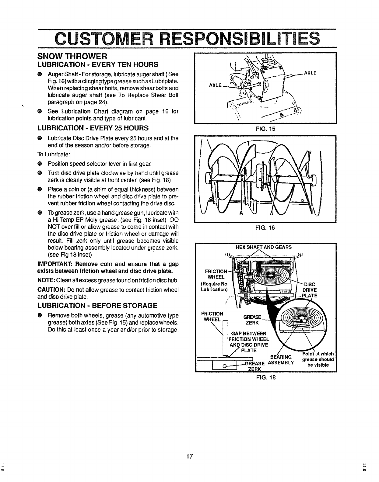
@ Auger Shaft- For storage, lubricate auger shaft ( See
Fig, 16) with aclinging type grease such as Lubriplate.
When replacing shear bolts, remove shear bolts and
lubricate auger shaft (see To Replace Shear Bolt
paragraph on page 24).,
@ See Lubrication Chart diagram on page 16 for
lubrication points and type of lubricant,
LUBRICATION - EVERY 25 HOURS
@ Lubricate Disc Drive Plate every 25 hours and at the
end of the season and/or before storage,
To Lubricate:
@ Position speed selector lever in first gear
@ Tum disc drive plate clockwise by hand until grease
zerk is clearly visible at front center (see Fig. 18)
@ Place a coin or (a shim of equal thickness) between
the rubber fdction wheel and disc drive plate to pre-
vent rubber friction wheel contacting the drive disc,
@ To grease zerk, use a hand grease gun, lubricate with
a Hi Temp EP Moly grease, (see Fig, 18 inset) DO
NOT over fill or allow grease to come in contact with
the disc drive plate or friction wheel or damage will
resulL Fill zerk only until grease becomes visible
below bearing assembly located under grease zerk,
(see Fig 18 inset)
IMPORTANT; Remove coin and ensure that a gap
exists between friction wheel and disc drive plate.
NOTE: Clean all excess grease found on friction disc hub.
CAUTION; Do not allow grease to contact friction wheel
and disc drive plate,
LUBRICATION - BEFORE STORAGE
@ Remove both wheels, grease (any automolive type
grease) both axles (See Fig 15) and replace wheels
Do this at least once a year and/or prior to storage,
AXLE
'_,
........AXLE
FIG. 15
FIG. 16
i i / iiii
HEX SHAFT AND GEARS
FRICTION
WHEEL
(Require No
Lubrication)
/
/
FRICTION
WHEEL
GREASE
ZERK
GAP BETWEEN
:RiCTION WHEEL
DISC DRIVE
DRIVE
..,PLATE
FIG. 18
17
.......................................................................................................... , ,, ,,,, ...............................
CUSTOM ILITIES
LUBRICATION .........
® Hex Shaft and Gears - Hex shaft and gears require
no lubrication All bearings and bushings are lifetime
lubricated and require no maintenance (See Fig. 18,
page 17).
NOTE: Any greasing or oiling of the above components
can cause contamination of the friction wheel Ifthe disc
ddve plate or friction wheel come in contact with grease
or oil, damage to the friction wheel will result.,
Should grease or oil come in contact with the disc drive
plate or friction wheel, be sure to clean the plate and
wheel thoroughly_
NOTE: For storage, the hex shaft and gears should be
wipedwith 5W30 motor oitto prevent rusting(See Fig. t8,
page 17).
@ Auger Gear Box - The auger gear box has been
factory lubricated for life. if for some reason lubricant
should leak out, have auger gear case checked by a
competent repairman.
ENGINE
LUBRICATION
FIG. 19
i, i i i i ....,i lira. I II.lJIL i HI] ,,i m.,
FIG. 20
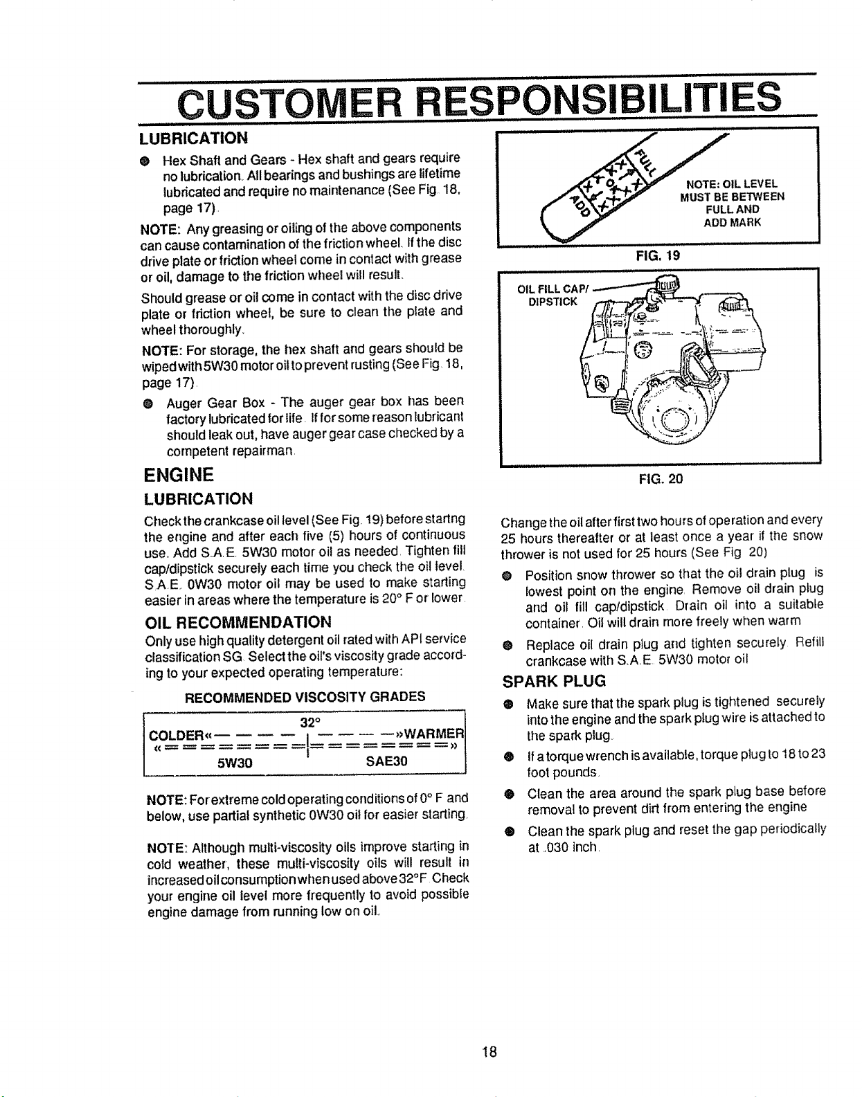
Check the crankcase oil level (See Fig. 19)before startng
the engine and after each five (5) hours of continuous
use.,Add S.,A.E. 5W30 motor oil as needed. Tighten fill
cap/dipstick securely each time you check the oil Ievel,
SrAE 0W30 motor oil may be used to make starting
easier in areas where the temperature is 20° F or lower.
OIL RECOMMENDATION
Only use high quality detergent oil rated with API service
classification SG Select the oi!'s viscosity grade accord-
ing to your expected operating temperature:
RECOMMENDED VISCOSITY GRADES
LDER_€ .{ _WARMER
5W30 SAE30
NOTE: Forextreme cold operating conditions of0° F and
below, use partial synthetic0W30 oil for easier starting
NOTE: Although multi-viscosity oils improve starting in
cold weather, these multi-viscosity oils will result in
increasedoilconsumptionwhen used above32°F Check
your engine oil level more frequently to avoid possible
engine damage from running low on oil,,
Change the oil after first two hour s ofoperation and every
25 hours thereafter or at least once a year if the snow
thrower is not used for 25 hours (See Fig 20)
e Position snow thrower so that the oil drain plug is
_owest point on the engine Remove oil drain plug
and oil fill capfdipstick Drain oil into a suitable
container. Oil will drain more freely when warm
0 Replace oil drain plug and tighten securely Refill
crankcase with S.AE 5W30 motor oil
SPARK PLUG
• Make sure that the spark plug is tightened securely
into the engine and the spark plug wire is attached to
the spark plug
® ifa torque wrench is available, torque plug to 18 to23
foot pounds,
® Clean the area around the spark plug base before
removal to prevent dirt from entering the engine
® Clean the spark plug and reset the gap periodically
at .030 inch.
18
_ CAUTION: ALWAYS DISCONNECT THE
SPARK PLUG WIRE AND TiE BACK
AWAY FROM THE PLUG BEFORE MAK-
ING ANY ADJUSTMENTS OR REPAIRS.
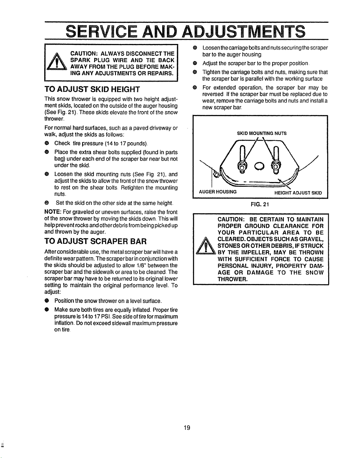
TO ADJUST SKID HEIGHT
This snow thrower is equipped with two height adjust-
ment skids, located on the outside of the auger housing
(See Fig°21). These skids elevate the front of the snow
thrower°
For normal hard surfaces, such as a paved driveway or
walk, adjust the skids as follows:
@
@
O
Check tire pressure (14 to 17 pounds).
Place the extra shear bolts supplied (found in parts
bag) under each end of the scraper bar near but not
under the skid_
Loosen the skid mounting nuts (See Fig 21), and
adjust the skids to allow the front of the snow thrower
to rest on the shear bolts. Retighten the mounting
nuts_
® Set the skid on the other side at the same height..
NOTE: For graveled or uneven surfaces, raise the front
of the snow thrower by moving the skids down. This will
help prevent rocks and other debris from being picked up
and thrown by the auger°
TO ADJUST SCRAPER BAR
After considerable use, the metal scraper barwifl have a
definite wear pattern,.The scraper bar in conjunction with
the skids should be adjusted to allow 1t8" between the
scraper bar and the sidewalk or area to be cleaned. The
scraper bar may have to be returned to itsoriginal lower
setting to maintain the original performance level_ To
adjust:
• Position the snow thrower on a level surface.
• Loosen thecarriage boltsand nuts securingthe scraper
bar to the auger housing.
® Adjust the scraper bar to the proper position.
@ Tighten the carriage bolts and nuts, making sure that
the scraper bar is parallel with the working surface
@ For extended operation, the scraper bar may be
reversed if the scraper bar must be replaced due to
wear, remove the carriage bolts and nuts and install a
new scraper bar_
SKID MOUNTING NUTS
AUGER HOUSING
HEIGHT ADJUST SKID
FiG, 21
CAUTION: BE CERTAIN TO MAINTAIN
PROPER GROUND CLEARANCE FOR
YOUR PARTICULAR AREA TO BE
_ CLEARED. OBJECTS SUCH AS GRAVEL,
STONES OR OTHER DEBRIS, IF STRUCK
BY THE IMPELLER, MAY BE THROWN
WITH SUFFICIENT FORCE TO CAUSE
PERSONAL INJURY, PROPERTY DAM-
AGE OR DAMAGE TO THE SNOW
THROWER.
O
Make sure both tires are equally inflated,Proper tire
pressure is 14to 17 PSt, See side of tire for maximum
inflation, Do not exceed sidewall maximum pressure
on tire.
!9
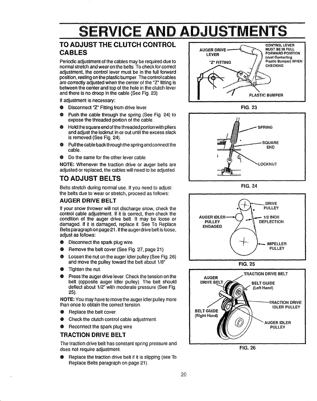
Periodic adjustment of the cables may be required due to
normal stretch and wear on the belts. To check for correct
adjustment, the control lever must be in the full forward
position, restingon the plasticbumper._The control cables
are correctly adjusted when the center of the "Z" fitting is
between the center and top of the hole in the ctutch lever
and there is no droop in the cable (See Fig._23)
If adjustment is necessary:
® Disconnect "Z" Fitting from drive lever,
@ Push the cable through the spring (See Fig 24) to
expose the threaded portion of the cable
® Holdthe square er_ofthe threaded portionwith pliers
and adjust the Iocknut in or out until the excess slack
is removed (See Fig. 24),
@ Pullthe cable backthroughthe spring and connect the
cable°
@ Do the same for'the other lever cable,
NOTE: Whenever the traction drive or auger belts are
adjusted or replaced, the cabtes will need to be adjusted
TO ADJUST BELTS
Belts stretch during norrnal use._If you need to adjust
AUGER MUST REIN FULL
LEVER FORWARD POSmON
(Just Contacting
"Z" FITTING Plastic Bumper) WHEN
CHECKING
PLASI']C BUMPER
FIG, 23
,__/SPRING
,LOCKNUT
FIG. 24
the belts due to wear or stretch, proceed as follows:
AUGER DRIVE BELT
If your snow thrower will not discharge snow, check the
control cable adjustmenL if it is correct, then check the
condition of the auger drive belt. It may be loose or
damaged., If it is damaged, replace it See To Replace
Belts paragraph on page 2t., Ifthe auger drive belt is loose,
adjust as follows:
® Disconnect the spark plug wire.
® Remove the belt cover (See Fig 27, page 21)
® Loosen the nut on the auger idler pulley (See Fig 26)
and movethe pulley toward the belt about t/8"
® Tighten the nut..
® Press the auger drive lever, Check the tension on the
belt (opposite auger idler pulley). The belt should
deflect about 112"with moderate pressure (See Fig.
25),
NOTE: You may have to move the auger idlerpulley more
than once to obtain the correct tension
® Replace the belt cover..
® Check the clutch control cable adjustment,.
® Reconnect the spark plug wire
TRACTION DRIVE BELT
PULLEY
ENGAGED
DR|VE
PULLEY
112INCH
DEFLECTION
IMPELLER
PULLEY
FIG, 25
I I /I IIIIIIII II II IIII II IIIIII
_TRACTION DRIVE BELT
AUGER
DRIVE BELT BELT GUI DE
(Left Hand)
BELT GUIDE
(Right Hand)
!IVE
IDLER PULLEY
AUGER IDLER
PULLEY
The traction drive belt has constant spring pressure and
does not require adjustment.
® Replace the traction drive belt if it is slipping (see To
Replace Belts paragraph on page 21).
FIG. 26
..... SE ....................CE ADJ.................................................................TS
TO REPLACE BELTS
The drive belts on this snow thrower are of special
construction and should be replaced with original
equipment belts available from your nearest Sears Store
or Service Center.
You will need the assistance of a second personwhile
replacingthe belts.
Drainthe gasolinefrom the fu el tankby removingthe fuel
liner Drain the gas and reinstallthe fuel line
DOORS, AWAY FROM FIRE OR FLAME.
AUGER DRIVE BELT
If your snow thrower will not discharge snow, and the
auger drive belt is damaged, replace it as follows:
® Disconnect the spark plug wire
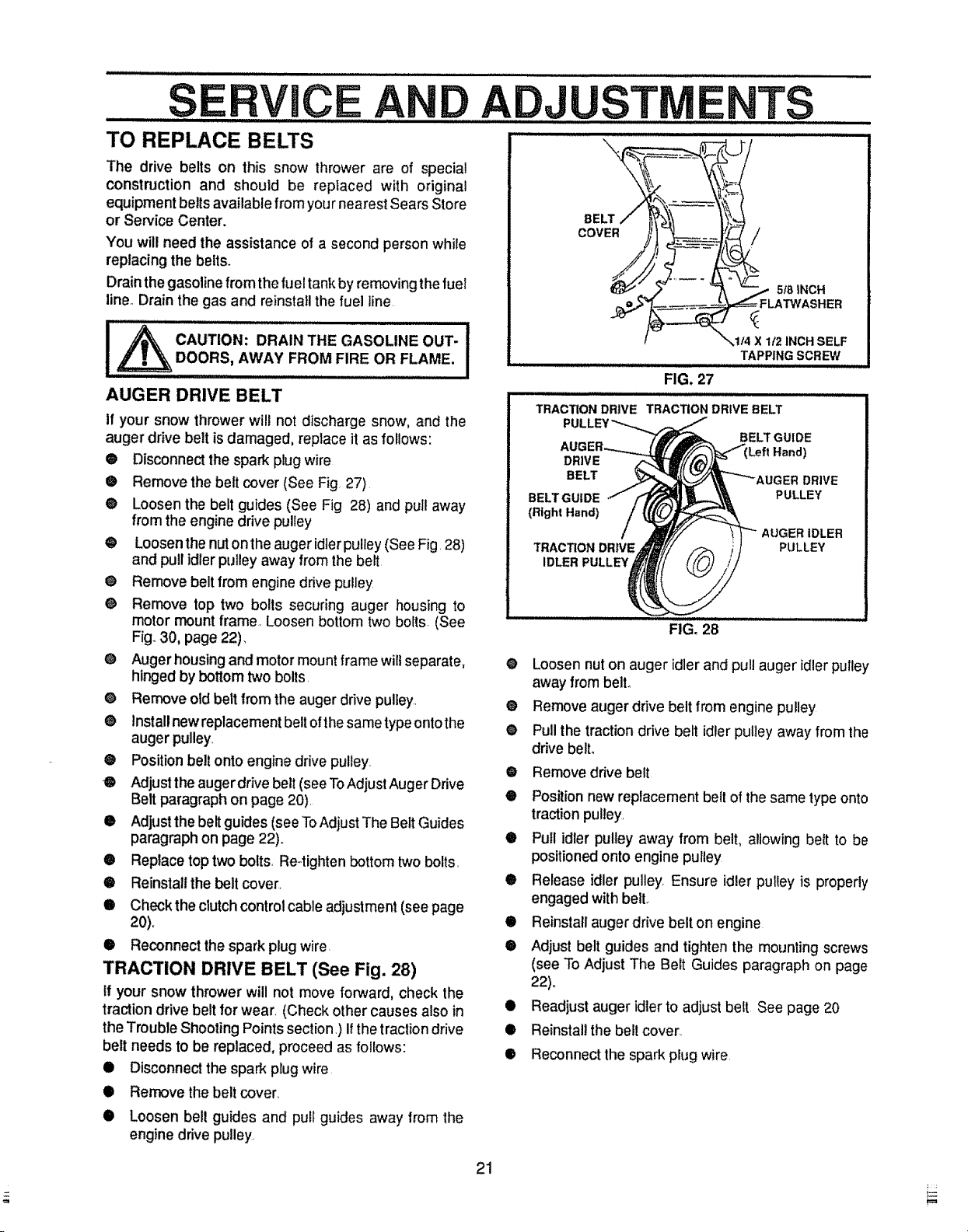
• Remove the belt cover (See Fig 27)
@ Loosen the belt guides (See Fig 28) and pull away
from the engine drive pulley
@ Loosen the nut onthe auger idler pulley (See Fig. 28)
and pull idler pulley away from the belt
@ Remove belt from engine drive pulley
@ Remove top two bolls securing auger housing to
motor mount frame, Loosen bottom two bolts. (See
Fig. 30, page 22),
@ Auger housing and motor mount frame wilt separate,
hinged by bottom two bolls.
@ Remove old belt from the auger drive pulley..
@ Install new replacement belt of thesame type ontothe
auger pulley.
@ Position belt onto engine drive pulley.
O Adjust the auger drive belt (see ToAdjust Auger Drive
Belt paragraph on page 20).
• Adjust the belt guides (see To Adjust The Belt Guides
paragraph on page 22).
• Replace top two bolts, Re-tighten bottom two bolts.
• Reinstall the belt cover_
@ Check the clutch control cable adjustment (see page
20).
@ Reconnect the spark plug wire.
TRACTION DRIVE BELT (See Fig. 28)
tf your snow thrower will not move forward, check the
traction drive belt for wear. (Check other causes also in
the Trouble Shooting Points section.) if the traction drive
belt needs to be replaced, proceed as follows:
• Disconnect the spark plug wire
@ Remove the belt cover,
@
@
®
0
@
@
@
@
®
0
0
®
iiii ilJllllllllllllllllllllllij i1¸/111i i
TRACTION DRIVE TRACTION DRIVE BELT
X 1/2 INCH SELF
TAPPING SCREW
iiiiHu
FIG. 27
DRIVE
BELT
BELT GUIDE
(Bight Hand)
TRACTION DRIVE
IDLER PULLEY
BELT GUIDE
DRIVE
PULLEY
AUGER IDLER
PULLEY
FIG, 28
Loosen nut on auger idler and pull auger idler pulley
away from belt@
Remove auger drive belt from engine pulley
Pull the traction drive belt idler pulley away from the
drive belt.
Remove drive belt
Positionnew replacement belt of the same type onto
traction pulley.
Pull idler pulley away from belt, allowing belt to be
positioned onto engine pulley
Release idler pulley Ensure idler pulley is properly
engaged with bell
Reinstall auger drive belt on engine
Adjust belt guides and tighten the mounting screws
(see To Adjust The Belt Guides paragraph on page
22).
Readjust auger idler to adjust belt See page 20
Reinstall the bell cover.
Reconnect the spark plug wire
@ Loosen bell guides and pull guides away from the
engine drive pulley.
21
S ...........CE ADJUST ..........TS
......... ..... Jl iiiii u i iiiiiii ,111,,,i / ,, ................ii : : : ................................... .
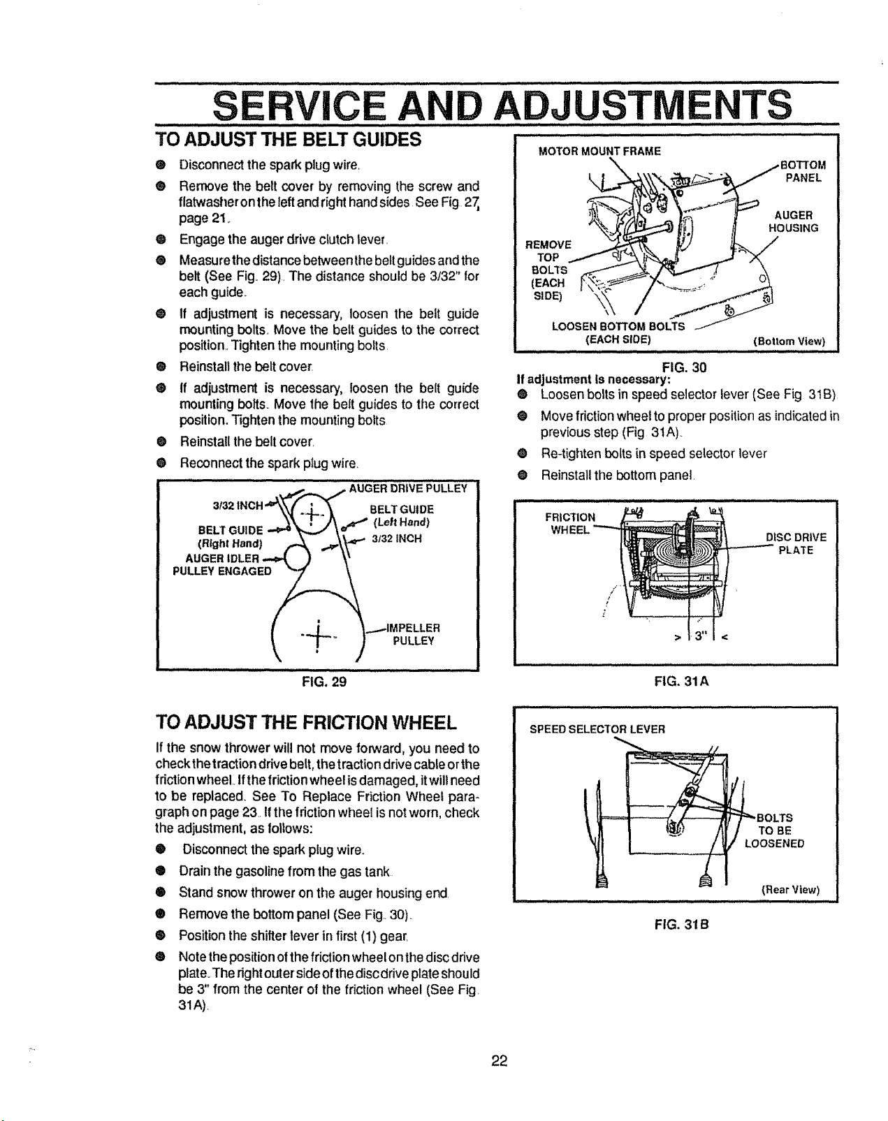
TO ADJUST THE BELT GUIDES ...................... .........................
MOTOR MOUNT FRAME
® Disconnect the spark plugwire.
® Remove the belt cover by removing the screw and
flatwasheron the leftand right hand sides See Fig 27,
page 21_
Q Engage the auger drive clutch lever.
® Measurethe distance betweenthe belt guides and the
belt (See Fig..29). The distance should be 3/32" for
each guide.,
@ tf adjustment is necessary, loosen the belt guide
mounting bolts. Move the beit guides to the correct
position,.Tighten the mounting bolts.
® Reinstall the belt cover.
® If adjustment is necessary, loosen the belt guide
mounting bolts. Move the belt guides to the correct
position. Tighten the mounting bolts
®
®
REMOVE
TOP
BOLTS
(EACH
(EACH SLOE)
FIG. 30
If adjustmentis necessary:
PANEL
AUGER
HOUSING
(Bottom View}
® Loosen bolts in speed selector lever (See Fig 31B)
• Move friction wheel to proper positionas indicatedin
previous step (Fig 3tA)..
Re-tighten bolts in speed selector lever
Reinstall the bottom panel.
Reinstall the belt cover.
Reconnect the spark plug wire.
........" : ......... ,--_ -,,-,,_,...__ AUaER_RiVEPULLEY
1NCH'W_ ._,.,. _ BELT GUIDE
3132
,4, .-.-\W
3132INCH
I .d _...-IMPELLER
_ T-'" ) PULLEY
®
O
FIG. 29
FRICTION
/
p
!
DISC DRIVE
PLATE
FIG. 31A
TO ADJUST THE FRICTION WHEEL
If the snowthrower will not move forward, you need to
checkthetraction drive belt,the tractiondrivecableorthe
f dction wheel Ifthe friction wheel is damaged,itwill need
to be replaced_See To Replace Friction Wheel para-
graphon page 23. Ifthe frictionwheel is not worn, check
the adjustment, as follows:
® Disconnectthe spark plugwire°
® Drain the gasolinefrom the gas tank
® Stand snow throweron the auger housing end.
® Remove the bottom panel (See Fig 30)..
® Positionthe shifter lever in first(1) gear.
• Notethe positionofthe friction wheelonthe disc drive
plate.The rightouterside of thedisc drive plateshould
be 3" from the center of the friction wheel (See Fig.
31A).
SPEED SELECTOR LEVER
_...- - ........ .. __ .......
FIG. 31B
=_BOLTS
TO BE
LOOSENED
(Rear View)
22
S CE ADJUSTNIE TS
TO REPLACE FRICTION WHEEL BOLT
Ifthe snow thrower willnot move forward, and the friclion
wheel is worn or damaged, you need to replace it as
follows: (First allow the engine to cool.)
_ CAUTION: DRAIN GASOLINEOUTDOORS
AWAY FROM FIRE OR FLAME.
® Drain the gasoline from the fuel tank by removing the
fuel line. Drain the fuel and reinstall the fuet line
Q Disconnect the spark plugwire
@ Stand the snow thrower up on the auger housing end
(See Fig. 33)_
® Remove the bottom panel (See Fig 30, page 22)_
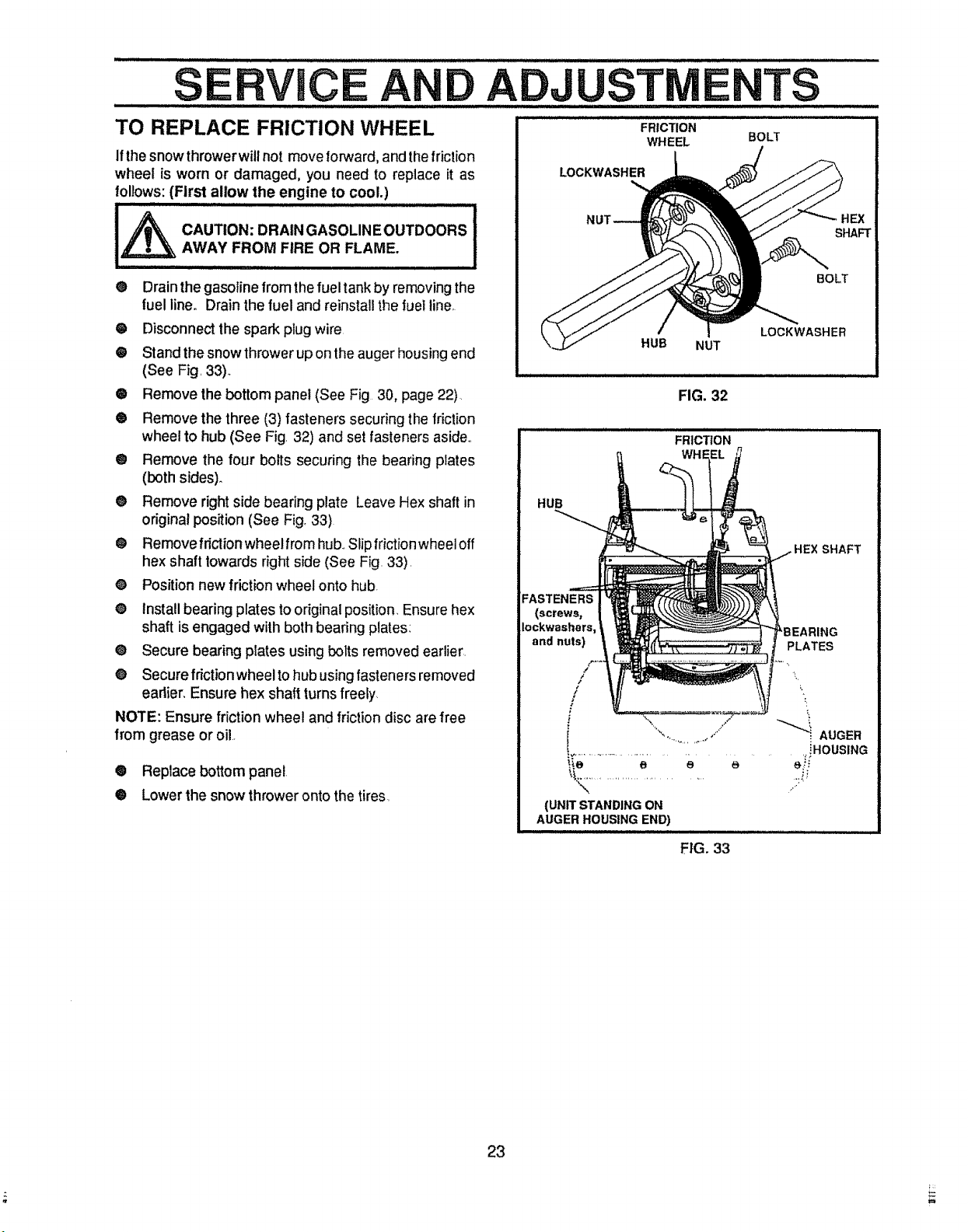
® Remove the three (3) fasteners securing the friction
wheel to hub (See Fig. 32) and set fasteners aside,.
@ Remove the four bolts securing the bearing plates
(both sides).
@ Remove right side bearing plate Leave Hex shaft in
original position (See Fig. 33)
® Removefriclionwheelfromhub..Slipfrictionwheeloff
hex shaft towards right side (See Fig. 33).
O Position new friction wheel onto hub.
• Install bearing plates to original position. Ensure hex
shaft is engaged with both bearing plates:
@ Secure bearing plates using bolts removed earlier.
@ Secure friction wheel to hub using fasteners removed
eadier. Ensure hex shaft turns freely
NOTE: Ensure friction wheel and friction disc are free
from grease or oil
• Replace bottom panel
@ Lower the snow thrower onto the tires,
FRICTION
WHEEL
LOCKWASHER
SHAFT
BOLT
HUB
NUT
FIG. 32
LOCKWASHER
FRICTION
HUB
SHAFT
FASTENERS
(screws,
Iockwashers,
and nuts)
PLATES
L
".... '/ _ AUGER
%,. . J _"
,,iHOUSING
"_K_............................. ..::i._
(UNIT STANDING ON
AUGER HOUSING END)
FIG. 33
23
SE CE ADJUST E TS
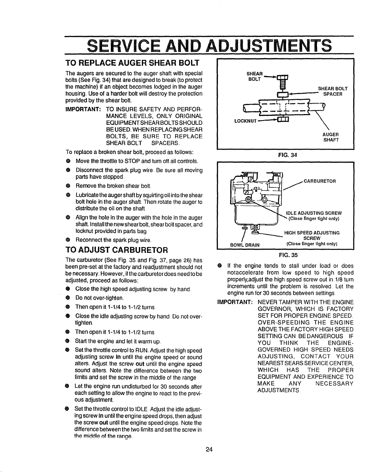
TO REPLACE AUGER SHEAR BOLT
The augers are secured to the auger shaft with special
bolts (See Fig° 34) that are designed to break (to protect
the machine) ff an object becomes lodged in the auger
housing. Use of a harder bolt will destroy the protection
provided by the shear bolt..
IMPORTANT: TO INSURE SAFETY AND PERFOR-
MANCE LEVELS, ONLY ORIGINAL
EQUIPMENT SHEAR BOLTS SHOULD
BE USED_WHEN REPLACING SHEAR
BOLTS, BE SURE TO REPLACE
SHEAR BOLT SPACERS.
To replace a broken shear bolt, proceed as !ollows:
@ Move the throttle to STOP and turn off all controls.
® Disconnect the spark plug wire. Be sure all moving
parts have stopped.
• Remove the broken shear bolt.
e
Lubricatethe auger shaft by squirting oilinto the shear
bolt hole in the auger shaft. Then rotate the auger to
distribute the oil on the shaft
O Align the hole in the auger with the hole in the auger
shaft Installt henew shear bolt, shear bolt spacer, and
Iocknut provided in parts bag
Q Reconnect the spark plug wire..
TO ADJUST CARBURETOR
The carburetor (See Fig. 35 and Fig. 37, page 26) has
been pre-set at the factory and readjustment should not
be necessary. However, ifthe carburetor does need to be
adjusted, proceed as follows:
Q Close the h_ghspeed adjusting screw by hand.
Do not over-tighten,
®
®
®
Then open it 1-114to t412 turns
Close the idle adjusting screw by hand. Do not over-
tighten.
• Then open it 1-114 to 14/2 turns
® Start the engine and let it warm up
O Set the throttle control to RUN..Adjust the high speed
adjusting screw in until the engine speed or sound
alters. Adjust the screw out until the engine speed
sound alters. Note the difference between the two
limits and set the screw in the middle of the range
® Let the engine run undisturbed for 30 seconds after
each setting to allow the engine to react to the previ-
ous adjustment..
® Set the throttle control to IDLE Adjust the idle adjust-
ing screw in until the engine speed drops, then adjust
the screw out until the engine speed drops. Note the
difference between the two limits and set the screw in
the middleof the range..
AUGER
SHAFT
. ,lllllll i,,,, ...................... - i ill
FIG, 34
ii/i N i i u illl llllllll i ii illlll
CARBURETOR
IDLE ADJUSTING SCREW
(Close finger tight only)
BOWL DRAIN
HIGH SPEED ADJUSTING
SCREW
(Close linger tight only)
FIG. 35
® tf the engine tends to stall under load or does
notaccelerate from low speed to high speed
properly,adjust the high speed screw out in 1/8 turn
increments until the problem is resolved. Let the
engine run for 30 seconds between settings
IMPORTANT: NEVER TAMPER WITH THE ENGINE
GOVERNOR, WHICH IS FACTORY
SET FOR PROPER ENGINE SPEED.
OVER-SPEEDING THE ENGINE
ABOVE THE FACTORY HIGH SPEED
SETTING CAN BE DANGEROUS IF
YOU THINK THE ENGINE-
GOVERNED HIGH SPEED NEEDS
ADJUSTING, CONTACT YOUR
NEAREST SEARS SERVICE CENTER,
WHICH HAS THE PROPER
EQUIPMENT AND EXPERIENCE TO
MAKE ANY NECESSARY
ADJUSTMENTS
24
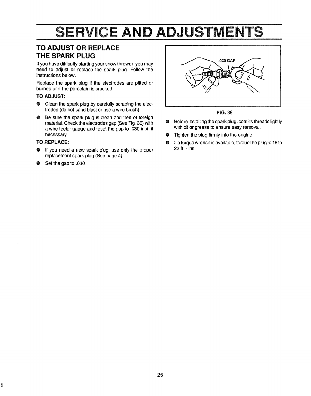
TO ADJUST OR REPLACE
THE SPARK PLUG
If youhave difficultystartingyoursnowthrower,you may
need to adjust or replace the spark plug Follow the
instructions below,,
Replace the spark plug if the electrodes are pitted or
burned or if the porcelain is cracked
TO ADJUST:
@ Clean the spark plug by carefully scraping the elec-
trodes (do not sand blast or use a wire brush).
® Be sure the spark plug is clean and free of foreign
material. Check the electrodes gap (See Fig 36) with
a wire feeler gauge and reset the gap to 030 inch if
necessary
TO REPLACE:
• If you need a new spark plug, use only the proper
replacement spark plug (See page 4)
• Set the gap to .030
,030 GAP
FIG. 36
O Beforeinstallingthe spark plug,coat itsthreadslightly
withoilor grease to ensure easy removal
• Tightenthe plug firmly intothe engine
O If a torque wrench is available, torque the plug to 18 to
23 ft ,- Ibs
25
..... ii1,11111111ii iiiiiii ................ _11_............ _1 _ ...................................................
CAUTION: NEVER STOREYOUR SNOW
THROWER INDOORS OR IN AN EN-
CLOSED, POORLY VENTILATED AREA
IF GASOLINE REMAINS IN THE TANK.
FUMES MAY REACH AN OPEN FLAME,
SPARK OR PILOT LIGHT FROM A FUR-
NACE, WATER HEATER, CLOTHES
DRYER, CIGARETTE, ETCo
To prevent engine damage (if snow thrower is not used
for more than 30 days) follow the steps below
SNOW THROWER STORAGE
@ Thoroughly clean the snow thrower_
@ Lubricate all lubrication points (see the Customer
Responsibilities section on pages 16-18)..
® Be sure that all nuts, bolts and screws are securely
fastened, inspect all visible moving parts for dam-
age, breakage and wear. Replace if necessary
O Touch up all rusted or chipped paint surfaces; sand
lightly before painting.
@ Cover the bare metal parts of the blower housing
auger' and the impeller with lust preventative, such
as a spray lubricanL
NOTE: A yearly checkupor tune-up by a SEARS Service
Centeris agoodwayto insurethatyoursnow throwerwill
provide maximumperformance for the next season.
ENGINE STORAGE
Gasoline must be removed or treated to prevent gum
deposits from forming tn the tank, filter, hose, and
carburetor during storage. Also during storage, al-
cohol blended gasoline that uses ethanol or metha-
nol (sometimes called gasohol) attracts water. It acts
on the gasoline to form acids which damage the
englne.
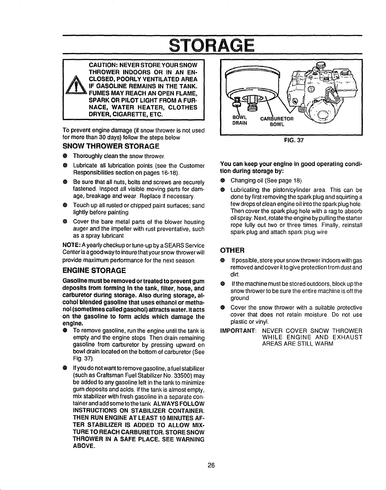
® To remove gasoline, run the engine untilthe tank is
empty and the engine stops. Then drain remaining
gasoline from carburetor by pressing upward on
bowl drain located on the bottom of carburetor (See
Fig, 37)_
O
tfyoudo not wantto remove gasoline, a fuel stabilizer
(such as Craftsman Fuel Stabilizer No_33500) may
be added to any gasoline left in the tank to minimize
gum deposits and acids., if the tank is almost empty,
mix stabilizer with fresh gasoline in a separate con-
tainer and add someto the tank ALWAYS FOLLOW
INSTRUCTIONS ON STABILIZER CONTAINER.
THEN RUN ENGINE AT LEAST 10 MINUTES AF-
TER STABILIZER IS ADDED TO ALLOW MIX-
TURE TO REACH CARBURETOR. STORE SNOW
THROWER IN A SAFE PLACE. SEE WARNING
ABOVE.
DRAIN
BOWL
IlL i
FIG. 37
You can keep your engine in good operating condi-
tion during storage by:
@ Changing oil (See page 18)
@ Lubricating the piston/cylinder area_ This can be
done by first removingthe spark plug and squirting a
few drops ofclean engineoil intothe spark plug hole,
Then cover the spark plug hole witha rag to absorb
oilspray, Next, rotate the engineby pullingthe starter
rope fully out two or three times Finally, reinstall
spark plug and attach spark plug wire
OTHER
@ If possible,store your snow thrower indoors with gas
removed and cover it togive protectionfrom dust and
dirt.
®
®
IMPORTANT:
Ifthe machine must be stored outdoors, block up the
snow thrower to be sure the entire machine is off the
ground
Cover the snow thrower with a suitable protective
cover that does not retain moisture Do not use
plastic or vinyls.
NEVER COVER SNOW THROWER
WHILE ENGINE AND EXHAUST
AREAS ARE STILL WARM
26
..... TFIOU LE SHOOTINGPOI TS
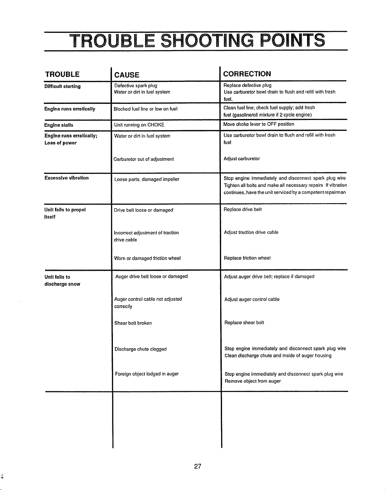
TROUBLE
Difficult starting
Englne runs erratically
Engine stalls
Engine runs erratically;
Loss of power
i i Ul
Excessive vibration
ii i i i i
Unit falls to propel
itself
Untt falls to
discharge snow
CAUSE
Defective spark pfug
Water or dirt in fuel system
Blocked fuel line or low on fuel
illll i/1/,,i,,,
Unit running on CHOKE
Water or dirtinfuel system
Carburetor out of adjustment
l llll ill
Loose parts; damaged impeIfer
i i i i ill /Jl /lllllllllllJlllllllllllll
Drive belt loose or damaged
Incorrect adjustment of traction
drive cable
Worn or damaged frictionwheel
Auger drive bett [oose or damaged
Auger control cable not adjusted
correctly
Shear bolt broken
Discharge chute clogged
Foreign object lodged in auger
CORRECTION
Replace defective pfug
Use carburetor bowl drain to flush and refiti with tresh
fuel,
Clean fue! line; check fuel supply; add fresh
fuel (gasofinetoi[ mixture il 2 cycle engine)
Move choke lever to OFF position
Use carburetor howl drain to flush and refill with tresh
fuel
Adiust carburetor
,, ,,,',,,,,,,,,,111111ii
Stop engine immediately and disconnect spark plug wire
Tighten all bolts and make all necessary repairs tf vibration
continues, have the unit serviced by a competent repairman
Replace drive belt
Adjust traction drive cable
Replace frictionwheel
Adjust auger drive belt; replace if damaged
Adjust auger control cable
Replace shear boit
Stop engine immediately and disconnect spark plug wire
Clean discharge chute and inside of auger housing
Stop engine immediately and disconnect spark plug wire
Remove object from auger
27
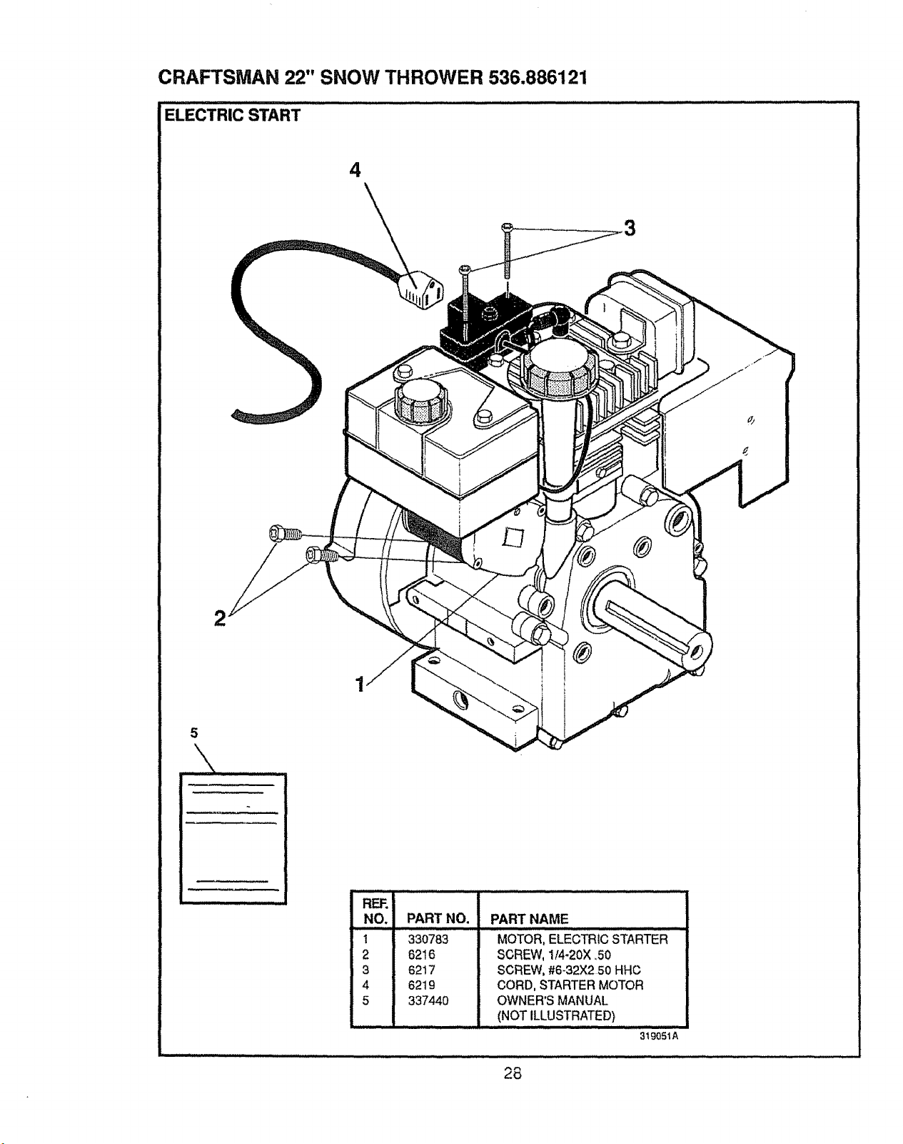
CRAFTSMAN 22" SNOW THROWER 536.886121
'E'LECTRICSTART........................................................ ......" ........................ :
4
\
2
~
REF.
NO. PART NO.
1 33o783
2 6216
3 6217
4 6219
5 337440
PART NAME
ill ,, ,,,,,,,,, ,,.
MOTOR, ELECTRic STARTER
SCREW,I/4.2oX_5o
SCREW, #6-32X2 50 HHC
CORD, STARTER MOTOR
OWNER'S MANUAL
(NOT ILLUSTRATED)
319051A
28
CRAFTSMAN 22" SNOW THROWER 536.886121
............... u / /J// ,,,=,,/,/ ,1,,,,i=,,/ ,===,/= ,,,,/,=,// =,/, / ii,,,,i,n,,,iJ,u,,n,u,n,, ,,,,
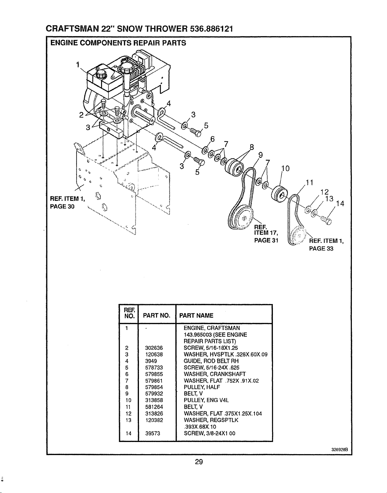
ENGINE COMPONENTS REPAIR PARTS
2 3
5
RER ITEM 1,
PAGE 30
3
5
9
REF.
ITEM 17,
PAGE 31
0
12
/ 13
14
PART NO, PART NAME
RER
NO.
1
2
3
6
7
8
9
lO
1t
12
13
14
302636
120638
3949
578733
579855
579861
579854
579932
313858
581264
313826
120382
39573
ENGINE, CRAFTSMAN
i43.965003 (SEE ENGINE
REPAIR PARTS LIST)
SCREW, 5t16-18X1.25
WASHER, HVSPTLK ..328X.60X,09
GUIDE, ROD BELT RH
SCREW, 5/t6-24X _625
WASHER, CRANKSHAFT
WASHER, FLAT .752X o91X.02
PULLEY, HALF
BELT, V
PULLEY, ENG V4L
BELT, V
WASHER, FLAT ,375X125X104
WASHER, REGSPTLK
,393X.68X 10
SCREW, 318-24Xl 00
29
326928B
ii
CRAFTSMAN 22" SNOW THROWER 536.886121
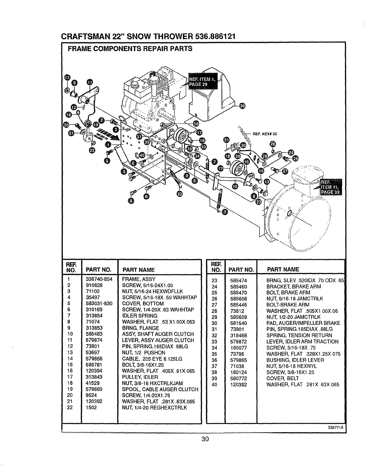
FRAME COMPONENTS REPAIR PARTS
REF.
NO.
1
2
3
4
5
6
7
8
9
10
11
12
!3
14
15
16
i7
18
19
20
21
22
ii
PART NAME
ii
PART NO.
336740-854
910828
71100
35497
583031-830
310169
313854
71074
313853
585483
579874
73801
53697
579856
585781
120394
313843
41529
579860
9524
120392
1502
PART NAME
FRAME, ASSY
SCREW, 5/16-24Xl .00
NUT) 5f16_24 HEXWDFLLK
SCREW, 5/16-18X .50 WAHHTAP
COVER, BOTTOM
SCREW, I/4-20X .63 WAHHTAP
IDLER SPRING
WASHER, FLAT 53 XI,00X.063
BRNG, FLANGE
ASSY, SHAFT AUGER CLUTCH
LEVER, ASSY AUGER CLUTCH
PIN, SPRING.165DIAX 88LG
NUT, 1t2 PUSHON
CABLE, .205 EYE 6125LG
BOLT, 3/8-16X! .25
WASHER, FLAT A06X .81X.065
PULLEY, IDLER
NUT, 318-16 HXCTRLKJAM
SPOOL, CABLE AUGER CLUTCH
SCREW, !/4-20X1.75
WASHER, FLAT ,281X .63X.065
NUT, 1/4-20 REGHEXCTRLK
REF.
NO. PART NO,
H,,, .. 1,111 i1
23 585474
24 585460
25 585470
26 585608
27 585446
28 73812
29 585609
3O 58154O
31 73801
32 318468
33 579872
34 180077
35 73795
36 579865
37 71O38
38 180124
39 580772
40 120392
BRNG, SLEV ,5201DX .70 ODX .65
BRACKET, BRAKE ARM
BOLT, BRAKE ARM
NUT, 9t16_18 JAMCTRLK
BOLT-BRAKE ARM
WASHER, FLAT .505X1.00X06
NUT, 1/2-20 JAMCTRLK
PAD, AUGER/IMPELLER BRAKE
PIN, SPRING. 165DIAX .88LG
SPRING, TENSION RETURN
LEVER, IDLER ARM TRACTION
SCREW, 5/16-t8X .75
WASHER, FLAT 328X1o25X 075
BUSHING, IDLER LEVER
NUT, 5/16-18 HEXNYL
SCREW, 3t8-16X !. 25
COVER, BELT
WASHER, FLAT 28tX 63X.065
3O
336771A
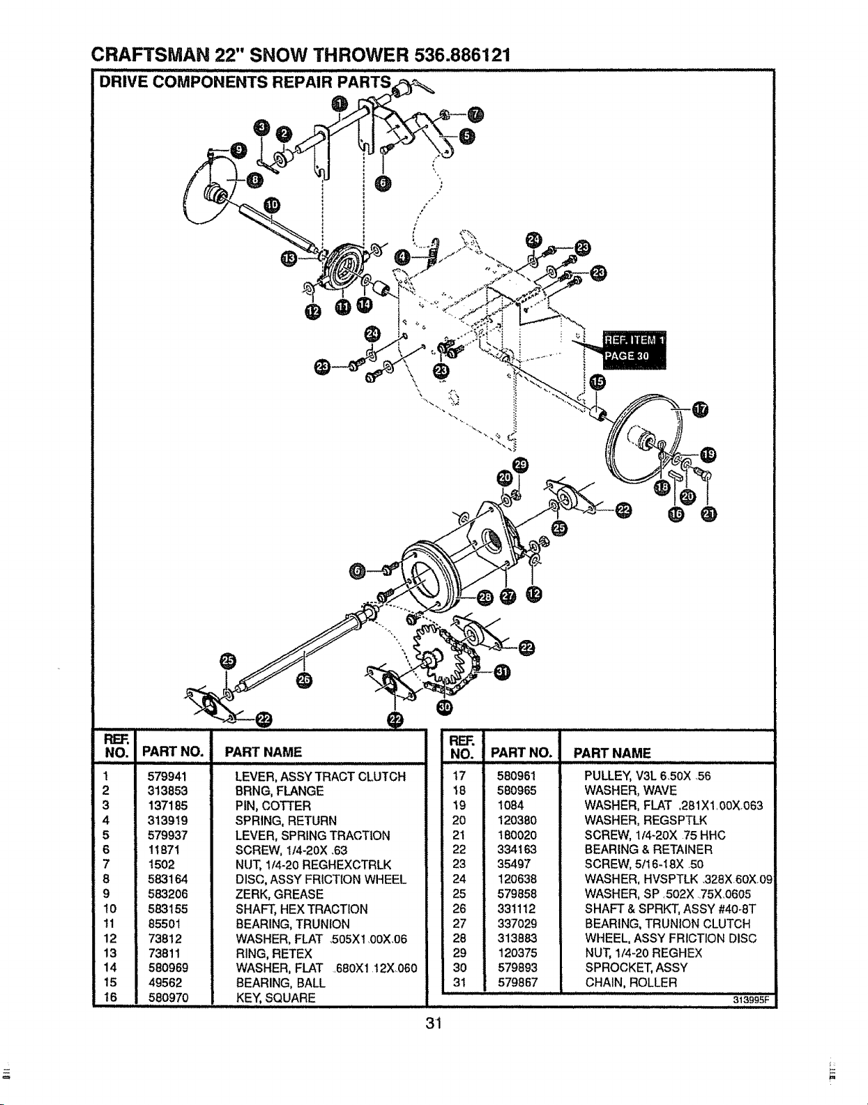
CRAFTSMAN 22" SNOW THROWER 536.886121
DRIVE cOMPONENTS REPAIR
0
0
RER
NO.
1
2
3
4
5
6
7
8
9
10
!1
12
!3
14
15
16
PART NO.
579941
313853
137185
313919
579937
1t871
1502
583164
583206
583155
85501
73812
73811
580969
49562
580970
PARTNAME
LEVER, ASSY TRACT CLUTCH
BRNG, FLANGE
PIN, COTTER
SPRING, RETURN
LEVER, SPRING TRACTION
SCREW, 114-20X .63
NUT, 1/4-20 REGHEXCTRLK
DISC, ASSY FRICTION WHEEL
ZERK, GREASE
SHAFT, HEX TRACTION
BEARING, TRUNION
WASHER, FLAT .505X1 00X,06
RING, RETEX
WASHER, FLAT ,680X1 12X,060
BEARING, BALL
KEY, SQUARE
O
R_FF.;
NO.
t7 '
!8
19
20
21
22
23
24
25
26
27
28
29
30
31
PART NO.
580961
580965
1084
120380
180020
334163
35497
12O638
579858
331112
337029
313883
12O375
579893
579867
PART NAME
PULLEY, V3L 650X 56
WASHER, WAVE
WASHER, FLAT ,281X1,00Xo063
WASHER, REGSPTLK
SCREW, 1/4-20X 75 HHC
BEARING & RETAINER
SCREW, 5t16-I8X +50
WASHER, HVSPTLK .328X60X+0
WASHER, SP ,502X ,.75X.0605
SHAFT & SPRKT, ASSY #40-8T
BEARING, TRUN1ON CLUTCH
WHEEL, ASSY FRICTION DISC
NUT, 1/4-20 REGHEX
SPROCKET, ASSY
CHAIN, ROLLER
313995F
3+1
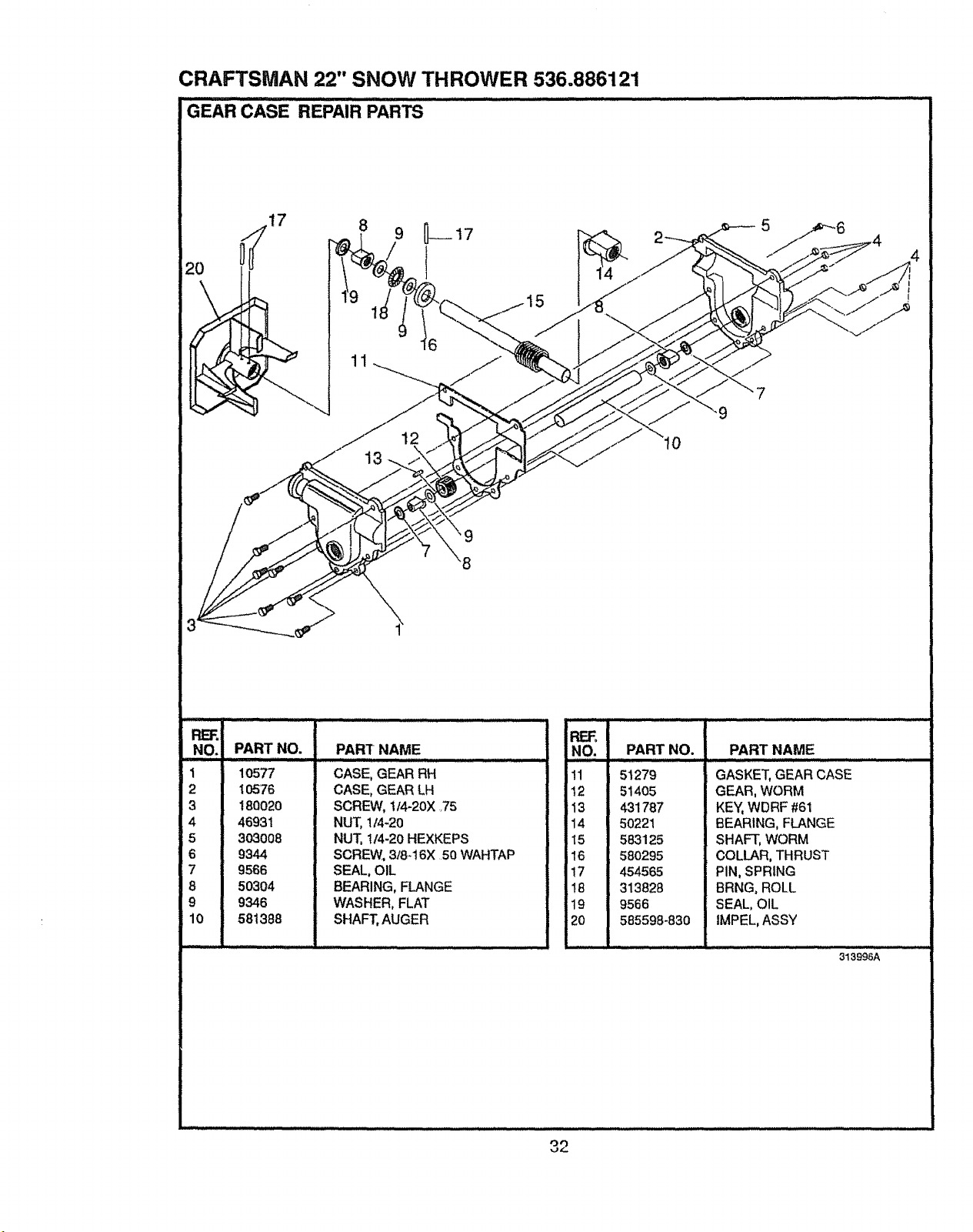
CRAFTSMAN 22" SNOW THROWER 536.886121
REF_
NO. PART NO.
I JJ IIIIIIII g,lllllllll
1 10577
2 10576
3 t8Q020
4 46931
5 3O3008
6 9344
7 9566
8 50304
9 9346
10 581388
PART NAME
ill ill i =U/U=U/LLU= ,w
CASE, GEAR RH
CASE, GEAR LH
SCREW, t/4-20X _75
NUT, 1/4_20
NUT, t/4-20 HEXKEPS
SCREW, 3/8.16X 50 WAHTAP
SEAL, OIL
BEARING, FLANGE
WASHER, FLAT
SHAFT, AUGER
PART NO. PART NAME
REF_
iNO,
!1
12
13
14
15
16
17
18
19
20
51279
51405
431787
50221
583125
580295
454565
313828
9566
585598-830
GASKET, GEAR CASE
GEAR, WORM
KEY, WDRF #61
BEARING, FLANGE
SHAFT, WORM
COLLAR, THRUST
PIN, SPRING
BRNG, ROLL
SEAL, OIL
iMPEL, ASSY
313996A
32
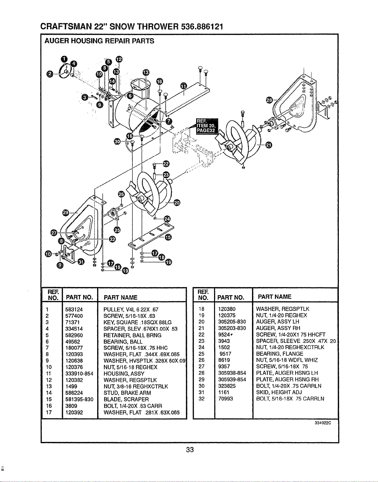
CRAFTSMAN 22" SNOW THROWER 536.886121
AUGER HOUSING REPAIR PAR'Ts ...........
REF.
NO. PART NO.
1
2
3
4
5
8
9
!0
11
12
13
14
15
16
17
58.3124
577400
71371
334514
582960
49562
180077
120393
120638
120376
333910-854
120382
1499
586224
581395-830
3809
120392
PART NAME
PULLEY, V4L 622X ,67
SCREW, 5/16-18X .63
KEY, SQUARE ..18SQX 88LG
SPACER, SLEV .676Xl..OOX .53
RETAINER, BALL BRNG
BEARING, BALL
SCREW, 5/16-18X .75 HHC
WASHER, FLAT ,.344X _69X_065
WASHER, HVSPTLK .328X 60X.09
NUT, 5f16-!8 REGHEX
HOUSING, ASSY
WASHER, REGSPTLK
NUT, 3/8-16 REGHXCTRLK
STUD, BRAKE ARM
BLADE, SCRAPER
BOLT, 114-20X,63 CARR
WASHER, FLAT 281X 63X.065
REF.
NO. PART NO.
18 120380
19 120375
20 305205-830
21 305203-830
22 9524_
23 3943
24 1502
25 9517
26 8619
27 9357
28 305938-854
29 305939-854
30 323825
31 1161
32 7O993
PART NAME
WASHER, REGSPTLK
NUT, 1/4-20 REGHEX
AUGER, ASSY LH
AUGER, ASSY RH
SCREW, 1/4-20X1.75 HHCFT
SPACER, SLEEVE 250X A7X 20
NUT, 1/4-20 REGHEXCTRLK
BEARING, FLANGE
NUT, 5/16-18 WDFL WHIZ
SCREW, 5/16-18X 75
PLATE, AUGER HSNG LH
PLATE, AUGER HSNG RH
BOLT, 1/4-20X ,.75CARRLN
SKID, HEIGHTADJ
BOLT, 5/16-18X .75 CARRLN
334922C
33
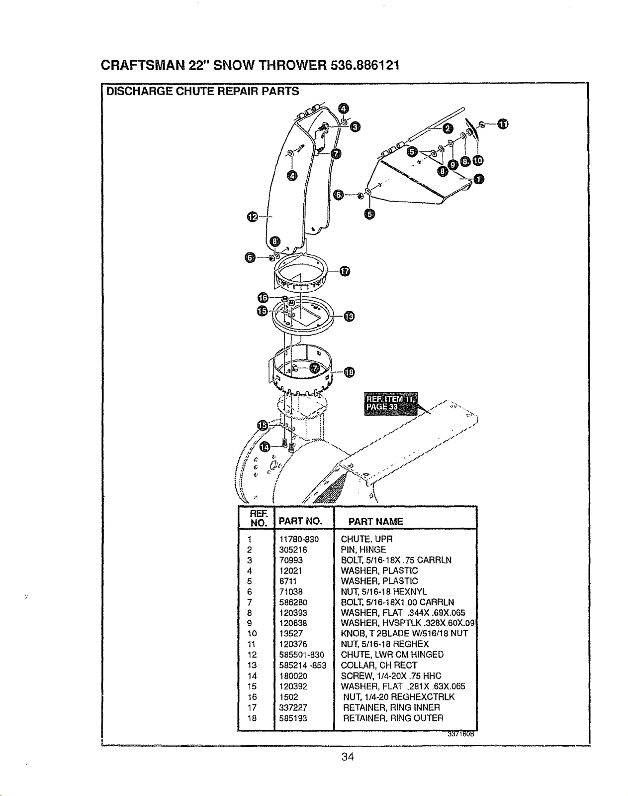
CRAFTSMAN 22" SNOW THROWER 536.886121
DISCHARGE CHUTE REPAIR PARTS......................................................................
O
l ,, I .1"
lil i l>.,,_J!l! "_,K
REE
NO. PART NO, PART NAME
IllL,± .... ImlC'UU ......
1 1!780_830 CHUTE, UPR
305216 PIN, HINGE
70993 BOLT, 5f16q 8X ,75 CARRLN
4 12021 WASHER, PLASTIC
5 6711 WASHER, PLASTIC
6 71038 NUT, 5tt6-18 HEXNYL
7 586280 BOLT, 5/16-18Xl .00 CARRLN
8 120393 WASHER, FLAT .344X .69X.065
9 120638 WASHER, HVSPTLK ,328X.60X.09
10 13527 KNOB, T 2BLADE Wt516f18 NUT
11 120376 NUT, 5/16-18 REGHEX
12 585501-830 CHUTE, LWR CM HINGED
13 585214 -853 COLLAR, CH RECT
t4 180020 SCREW, 1/4-20X .75 HHC
15 t20392 WASHER, FLAT .281X °63X.065
16 1502 NUT, 1/4-20 REGHEXCTRLK
17 337227 RETAINER, RING INNER
18 585193 RETAINER, RING OUTER
3_:,ieo_
34
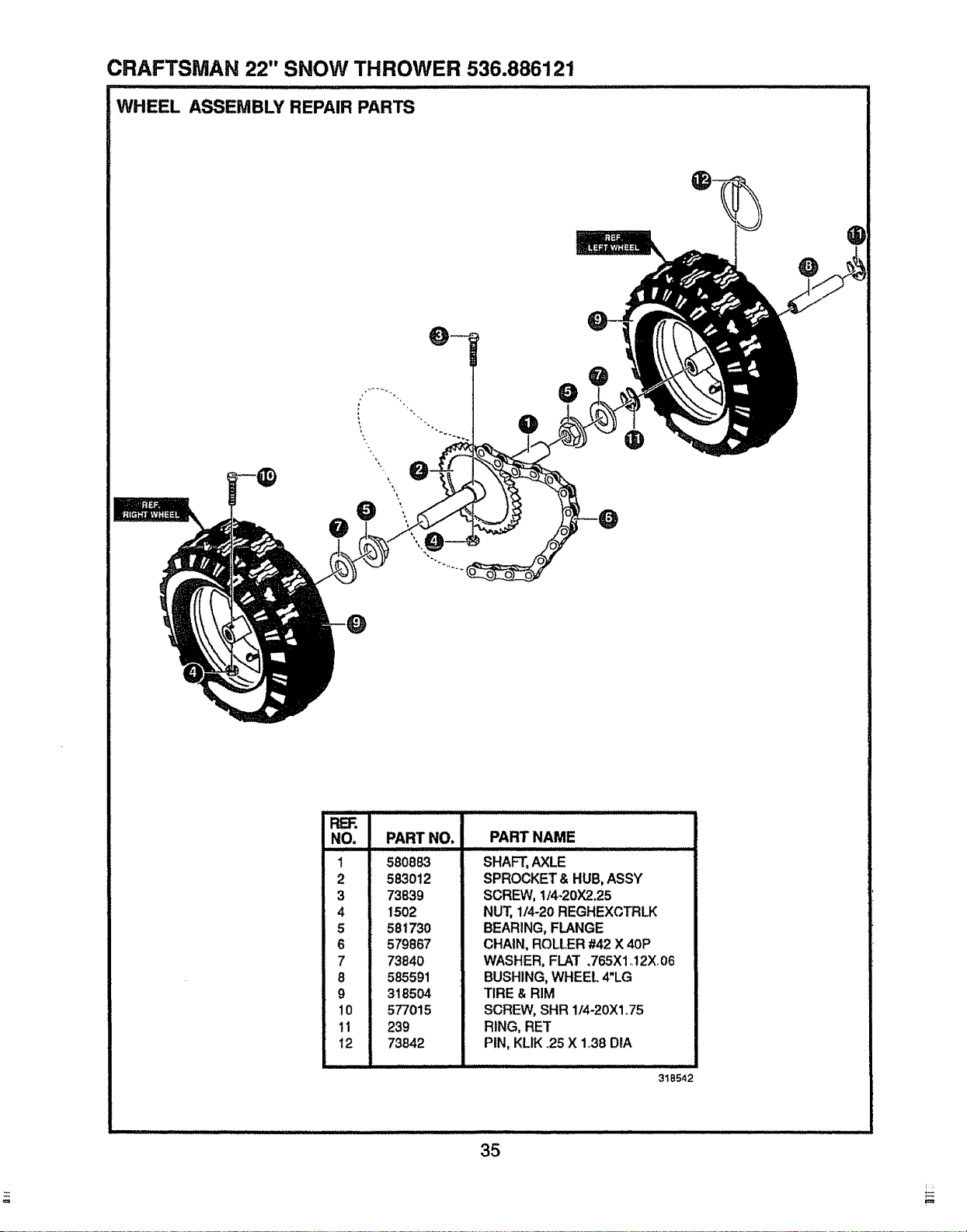
CRAFTSMAN 22" SNOW THROWER 536.886121
lllllr,,H Hi l lll
WHEEL ASSEMBLY REPAIR PARTS
@
RER
NO,
1
2
3
4
5
6
7
8
9
10
ti
t2
PART NAME
PART NO.
580883
583012
73839
1502
581730
579867
73840
585591
318504
577015
239
73842
SHAFT, AXLE
SPROCKET & HUB, ASSY
SCREW, I/4-20)(2.25
NUT, t14-20 REGHEXCTRLK
BEARING, FLANGE
CHAIN, ROLLER #42 X 40P
WASHER, FLAT .765X1 _12X06
BUSHING, WHEEL 4"LG
TIRE & RIM
SCREW, SHR 1/4-20X1.75
RING, RET
PIN, KLIK .25 X 138 DtA
318542
35
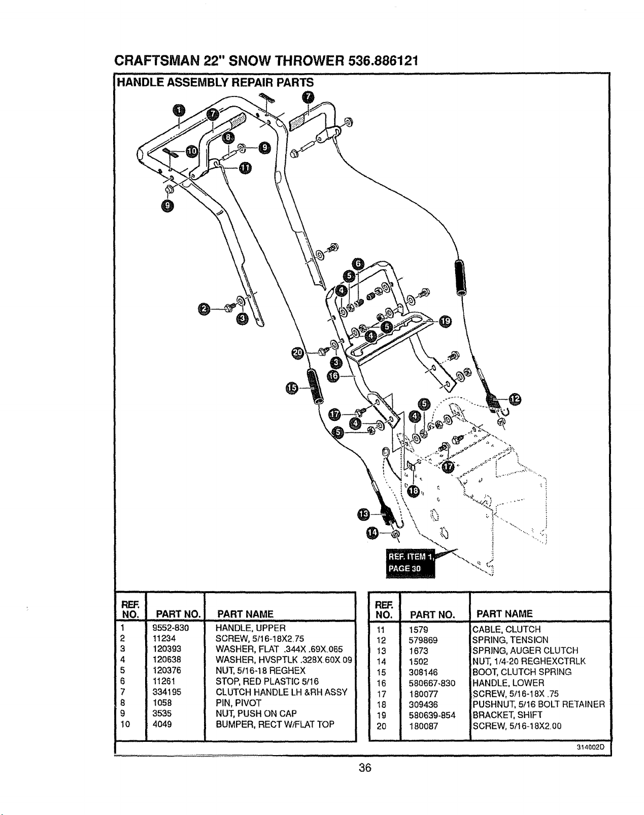
CRAFTSMAN 22" SNOW THROWER 536.886121
HANDLE ASSEMBLY REPAIR PARTS ........................... .....
,,
NO. PART NO,
1 9552-830
2 11234
3 120393
4 120638
5 120376
6 11261
7 334195
8 1058
9 3535
10 4049
PART NAME
HANDLE, UPPER
SCREW, 5116-t 8X275
WASHER, FLAT .344X .69X_065
WASHER, HVSPTLK .328X 60X.09
NUT, 5116-18 REGHEX
STOP, RED PLASTIC 5/16
CLUTCH HANDLE LH &RH ASSY
PIN, PIVOT
NUT, PUSH ON CAP
BUMPER, RECT W/FLAT TOP
RF_,,
NO.
17
12
13
14
15
16
17
18
19
20
PART NO,
1579
579869
1673
1502
308146
580667-830
180077
309436
580639_854
180087
' i .................... Jl,,
PART NAME
CABLE, CLUTCH
SPRING, TENSION
SPRING, AUGER CLUTCH
NUT, 114-20 REGHEXCTRLK
BOOT, CLUTCH SPRING
HANDLE, LOWER
.SCREW, 5/16-18X .75
PUSHNUT, 5/t6 BOLT RETAINER
BRACKET, SHIFT
SCREW, 5116-18X200
314002D
36
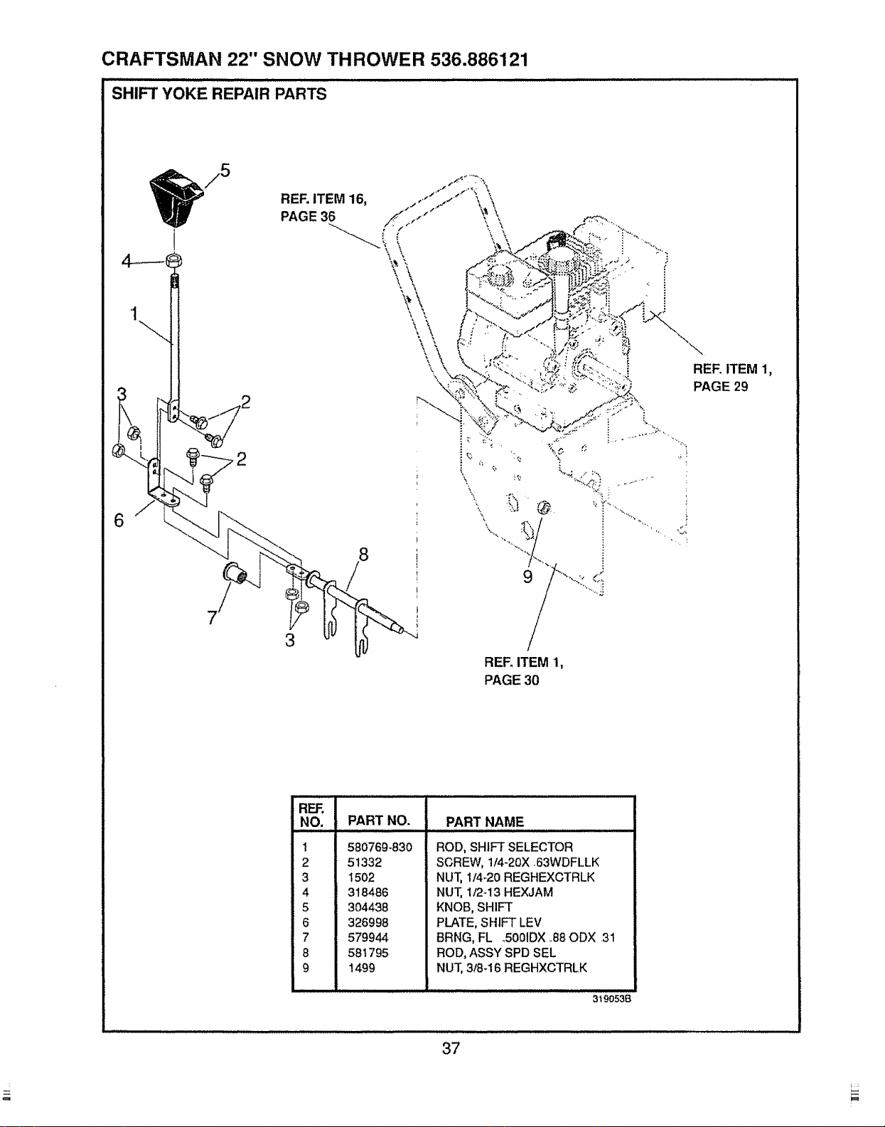
CRAFTSMAN 22" SNOW THROWER 536.886121
SHIFT YOKE REPAIR PARTS
i
REF. ITEM 16,
PAGE 36
Y\
\.
\
3
\
REF. ITEM 1,
PAGE 30
REF. ITEM 1,
PAGE 29
REF.
NO. PART NO.
1 580769-830
2 51332
3 t502
4 318486
5 304438
6 326998
7 579944
8 581795
9 1499
PART NAME
ROD, SHIFT SELECTOR
SCREW, 1/4-20X 63WDFLLK
NUT, 1/4-20 REGHEXCTRLK
NUT, 112-!3 HEXJAM
KNOB, SHIFT
PLATE, SHIFT LEV
BRNG, FL oS001DX,,88ODX 31
ROD, ASSY SPD SEL
NUT, 3!8_16 REGHXCTRLK
319053B
37
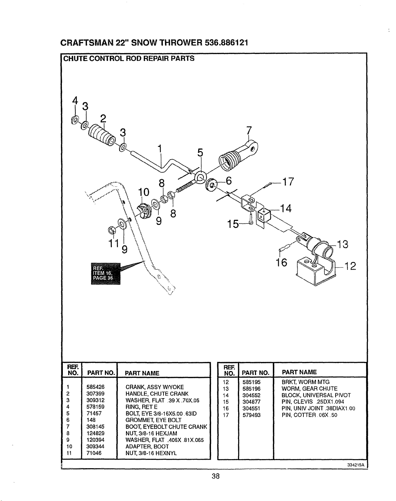
CRAFTSMAN 22" SNOW THROWER 536.886121
CHUTE CONTROL ROD REPAIR PARTS
NO. PART NO. PART NAME
. ........ m .....
1 585426
2 307399
3 309312
4 578159
5 71457
6 148
7 308145
8 124829
9 120394
10 309344
1! 71046
CRANK, ASSY W/YOKE
HANDLE, CHUTE CRANK
WASHER, FLAT ,39 X +70X+05
RING, RET E
BOLT, EYE 3/8-16X5+00,631D
GROMMET, EYE BOLT
BOOT, EYEBOLT CHUTE CRANK
NUT, 3/8+t 6 HEXJAM
WASHER, FLAT +406X ,81X+065
ADAPTER, BOOT
NUT, 318-16 HEXNYL
Pt_Fi
NO. PARr NO.
12 585195
13 585196
14 304552
15 3o4877
t6 304551
17 579493
PART NAME
BRKT, WORM MTG
WORM, GEAR CHUTE
BLOCK, UNIVERSAL PIVOT
PIN, CLEVIS 25DX1.094
PIN, UNIV JOINT 38DIAX1 00
PIN, COTTER. 06X.50
::: m_l_ .... m, . i- _- • i ............ ,,,,,,•,.,:,:•:: .......... ._. __:_
38
334215A
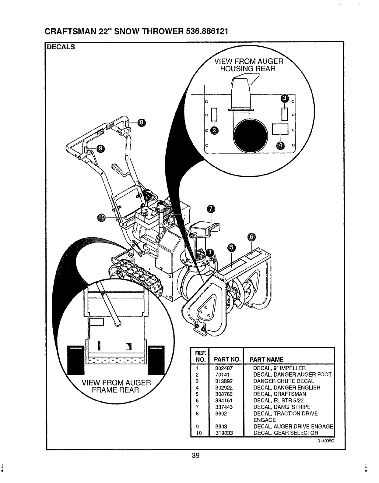
CRAFTSMAN 22" SNOW THROWER 536.886121
!DECALS
ViEW FROM AUGER
HOUSING REAR
@
VIEW FROM AUGER
FRAME REAR
9
10
PART NO. PART NAME
,,=,,i
302487 DECAL, 9" IMPELLER
70141
313892
302922
3O8766
334151
337443
3902
3903
319033
DECAL, DANGER AUGER FOOT
DANGER CHUTE DECAL
DECAL, DANGER ENGLISH
DECAL, CRAFTSMAN
DECAL, EL STR 5/22
DECAL, DANG STRIPE
DECAL, TRACTION DRIVE
ENGAGE
DECAL, AUGER DRIVE ENGAGE
DECAL, GEAR SELECTOR
314005C
39
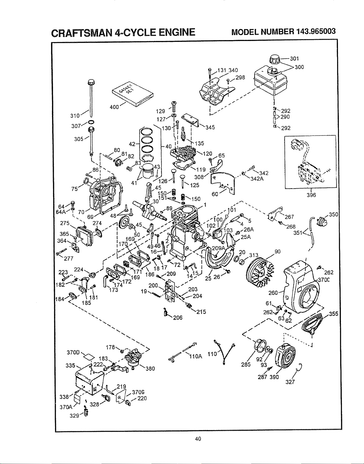
CRAFTSMAN 4-CYCLE ENGINE MODELNUMBER143.965003
310_ l 400
307"_
305/! 80
L
"r.,
69
274
i
I
117
,%
>
90 /
203
L206 215
285
93 /
287 390
327
32
329
40
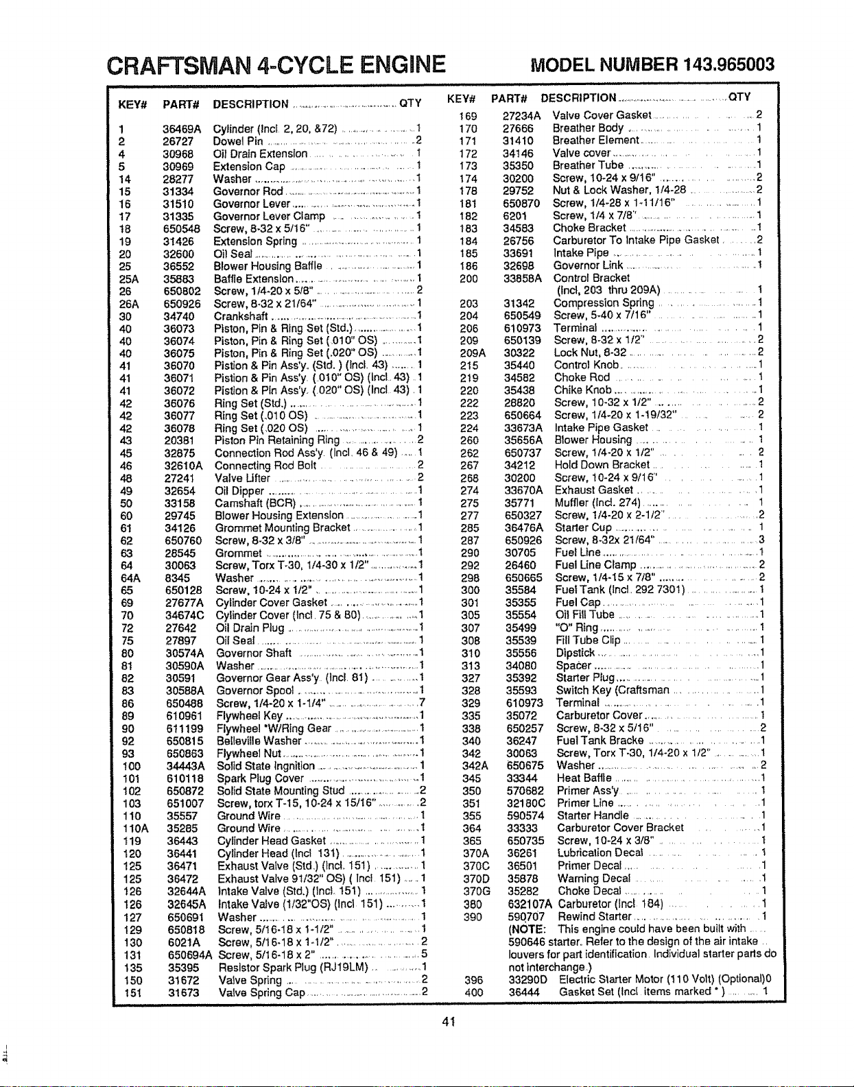
CRAFTSMAN 4-CYCLE ENGINE MODELNUMBER143.965003
KEY# PART#
1 36469A
2 26727
4 30968
5 30969
14 28277
15 31334
16 31510
17 31335
t8 650548
19 31426
20 32600
25 36552
25A 3588-3
26 650802
26A 650926
30 34740
40 36073
40 36074
40 36075
41 36070
41 36071
41 36072
42 36076
42 36077
42 36078
43 20381
45 32875
46 32610A
48 27241
49 32654
50 33158
60 29745
6! 34126
62 650760
63 285=[5
64 30063
64A 8345
65 650128
69 27677A
70 34674C
72 27642
75 27897
80 30574A
81 30590A
82 30591
8.3 30588A
86 650488
89 610961
90 611199
92 650815
93 650863
! 00 34443 A
101 610118
102 650872
103 651007
110 35557
110A 35285
119 36443
120 36441
125 36471
125 36472
126 32644A
126 32645A
127 650691
129 650818
130 6021A
131 650694A
135 35395
150 31672
151 31673
DESCRIPTION ........................................... QTY
Cylinder (incl 2, 20, &72) ..............................1
Dowel Pin .................................................... 2
Oil Drain Extension .......................... 1
Extension Cap ........................................ t
Washer ......................................................... 1
Governor Rod ..........................................................1
Governor Lever ...............................................1
Governor Lever Clamp ............................ 1
Screw, 8.32 x 5116" •.....................................1
Extension Spring ........................................ 1
Oil Seal ...................................................... 1
Blower Housing Baffle .................................1
Baffle Extension ...................................... 1
Screw, 1!4-20 x 518" .......................................2
Screw, 8.32 x 21164" ......................................1
Crankshaft ............................................................1
Piston, Pfn & Ring Set (Std.) ..........................1
Piston, Pin & Ring Set (0t0" OS) ........... 1
Piston, Pin & Ring Set (.020" OS) .................1
Pistion & Pin Ass'y. (Std.) (incL 43) ....... 1
Pistion & Pin Ass'y. (010" OS) (tncl. 43) 1
Pistton & Pin Ass'y. (020" OS) (Incl 43). 1
Ring Set (Std.) .............................................. 1
Ring Set (_010 OS) ........................................1
Ring Set (.020 OS) ................................... 1
Piston Pin Retaining Ring ......................... 2
Connection Rod Ass'y. (Incl. 46 & 49) ..... t
Connecting Rod Bolt ...................... 2
Valve Ufter .......................................... 2
Oil Dipper ................................................. 1
Camshaft (BCR) ...............................................1
Blower Housing Extension ...............................1
Grommet Mounting Bracket ..................... 1
Screw, 8-32 x 318". ....................................... 1
Grommet ..........................................................1
Screw, Torx T-30, 114-30 x t/2" ..................1
Wash er ........................................................... 1
Screw, 10-24 x 1/2", ........................................1
Cylinder Cover Gasket ................................ t
Cylinder Cover (incl. 75 & 80) ........................1
Oil Drain Plug ..................................................!
OI! Seal ............................................................ 1
Governor Shaft ........................................... 1
Washer ........................................................... t
Governor Gear Ass'y (incl. 61) ............... t
Governor Spool ............................................. 1
Screw, 114-20 x 1-1f4". .................................7
Flywheel Key ...................................................1
Flywheel "WiRing Gear ......................................1
BelleviUe Washer ............................................1
Flywheel Nut ...................................................I
Solid State tngnition ................................................1
Spark Plug Cover ....................................... !
Solid State Mounting Stud ....................... 2
Screw, torx T-15, 10-24 x 15/16". ............. 2
Ground Wire ................................................t
Ground Wire ....................................... 1
Cylinder Head Gasket ...................................1
Cylinder Head (lncl 13t) ................................t
Exhaust Valve (Std.) (lnc!. 151 ) .............. t
Exhaust Valve 91/32" OS) ( lncl 151) ......1
Intake Valve (Std.) (lnct 151) .................... 1
intake Valve (1/32"OS) (Inct 151) ........... 1
Washer .....................................................1
Screw, 5ft 6-18 x t -112" .......................... t
Screw, 5fl 6-18 x 1-t/2". ....................... 2
Screw, 5116-18 x 2". .............................. 5
Resistor Spark Plug (RJ19LM) ................. 1
Valve Spring ...........................................2
Valve Spring Cap .............................................2
KEY#
169
17O
171
172
I73
t74
t78
181
I82
t83
184
t85
186
2O0
203
204
206
209
209A
215
2t9
220
222
223
224
260
262
267
268
274
275
277
285
287
290
292
298
300
301
3O5
307
308
310
313
327
328
329
335
338
340
342
342A
345
350
35t
355
364
365
370A
370C
370D
370G
380
390
398
400
PART#
27234A
27666
31410
34146
35350
30200
29752
650870
6201
34583
26756
33691
32698
33858A
31342
650549
610973
650139
30322
35440
34582
35438
28820
650664
33673A
35656A
650737
34212
30200
33670A
35771
650327
36476A
650926
30705
26460
650665
35584
35355
35554
35499
35539
35556
34080
35392
35593
610973
35072
650257
36247
30063
650675
33344
570682
32180C
590574
33333
650735
36261
36501
35878
35282
DESCRIPTION ..................................................QTY
Valve Cover Gasket ....................... 2
Breather Body ................................... 1
Breather Element ............................ 1
Valve cover .............................. 1
Breather Tube .................................... 1
Screw, 10-24 x 9/16" ......................... 2
Nut & Lock Washer, 114-28 ................... 2
Screw, i/4-28 x 1-11tl 6" . .................. 1
Screw, t14 x 7/8" ............................... 1
Choke Bracket ............................................ !
Carburetor To Intake Pipe Gasket ........ 2
Intake Pipe ..................................... t
Governor Link .................................... !
Control Bracket
(Inct, 203 thru 209A) ......................... t
Compression Spring ....................... t
Screw, 5-40 x 7/16" ......................... 1
Terminal ....................................... 1
Screw, 8-32 x 1t2" ............................. 2
Lock Nut, 8-32 ................................ 2
Centre! Knob ............................. 1
Choke Rod ........................ t
Chike Knob ................................. 1
Screw, 10-32 x !t2" ...................... 2
Screw, 1!4-20 x 1-19/32" ................ 2
Intake Pipe Gasket ............... t
Blower Housing ......................... 1
Screw, 1/4-20 x 1t2" ........... 2
Hold Down Bracket .................. 1
Screw, t0-24 x 9/16" ............. 1
Exhaust Gasket ....................... 1
Muffler (Incl. 274) ..................... 1
Screw, 114-20 x 2-112". .................. 2
Starter Cup .................................... 1
Screw, 8.32x 21164". ..................... 3
Fuel Llne................................................. 1
Fuet Line Clamp .............................................2
Screw, 114-I5 x 7t8". ...................... 2
Fuel Tank (Incl. 292 730!) ....................... 1
Fuel Cap ........................................ 1
OilFIllTube .......................................1
"O" Rtng ......................................... !
Fill Tube Clip ................................ 1
Dipstick ......................................... 1
Spacer ............................................. 1
Starter Plug ........................................ 1
Switch Key (Craftsman ................... 1
Terminal ................................... 1
Carburetor Cover ............................... t
Screw, 8-32 x 5116" ..................... 2
Fuel Tank Bracke ................................ 1
Screw, Torx T.30, 1/4-20 x 1;2" ............... 1
Washer ................................................ 2
Heat Baffle .................................... !
Primer Ass'y............................... 1
Primer Line ........................... 1
Starter Handle ....................... 1
Carburetor Cover Bracket ........... 1
Screw, 10-24 x 3/8" ............. t
LubricationDecal ................... t
Primer Decal ................. 1
Warning Decal ........................ 1
Choke Decal ................ 1
632107A Carburetor (Inct t84) .............. 1
59Q707 Rewind Starter ................................. 1
(NOTE: This engine could have been built with ......
590646 starter.. Refer to the design of the air intake ..
louvers for part identification Individual starter paris do
not interchange..)
33290D Electric Starter Motor (110 Volt) (Optional)0
36444 Gasket Set (Incl items marked " ) ........... 1
4I
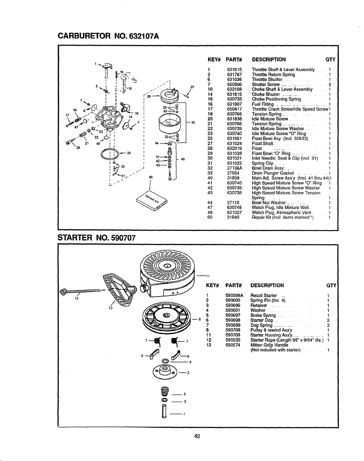
CARBURETOR NO. 632107A
L.. _,
STARTER NO. 590707
KEY# PART# DESCRIPTION
1 631615
2 631767
6 631036
7 650506
10 632108
14 631815
t5 630735
t6 631807
17 650417
18 630766
20 631838
21 630766
22 630739
23 630740
25 631951
27 631024
28 632019
29 631028
30 631021
31 631022
32 27136A
33 27554
40 31639
41 630740
42 630739
43 630738
44 27110
47 630748
48 631027
60 31840
QTY
Thrett_eShaft & Lever Assembly . 1
Throttle Return Spring ....... 1
Throttle Shutter ............... 1
Shutter Screw .......................... 2
Choke Shaft & Lever Assembly. 1
Choke Shutter ........................ 1
Choke Positioning Spring ...... t
Fuel Fitting ................................... I
Throttte Crack Screwtldle Speed Screw 1
Tension Spring ...................... I
ldte Mixture Screw ............. 1
Tension Spring ..................... 1
Idle Mixture Screw Washer . 1
idle M_xture Screw "O" Ring . t
Float Bowl Asy (lncl 32&33) 1
Float Shaft .......... 1
Float ............. 1
Float Bowl "O" Ring ........... i t
_nlet Needle, Seat & Clip (Incl 31 } i
Spring Clip .... t
Bowl Drain Assy .... 1
Drain Plunger Gasket ........ !
Main Adj. Screw Ass'y (Incl. 41 thru 44)1
High Speed Mixture Screw "O" Ring 1
High Speed Mixture Screw Washer !
High Speed Mixture Screw Tension
Spring ........... 1
Bowl Nut Washer ............... 1
Welch Plug, Idle Mixture Well. 1
Welch Pfug, Atmospheric Vent. 1
Repair Kit (Incl items marked ") 1
KEY#
1
2
3
4
5
--8 6
7
8
11
t2
13
PART#
59O599A
590600
590696
590601
590697
590698
590699
59o709
590708
590535
590574
DESCRIPTION QTY
Recoil Starter .... 1
Spring Pin (Inc 4) ....... t
Retainer ........... 1
Washer .......... I
Brake Spring .............. 1
Starter Dog .......... 2
Dog Spdng ................... 2
Pulley & rewind Ass'y 1
Starter Housing Ass'y................. 1
Starter Rope (Length 98" x 9t64" dia ) 1
Mitten Gri[p Handle
(Not included with starter) ....... 1
_3
42
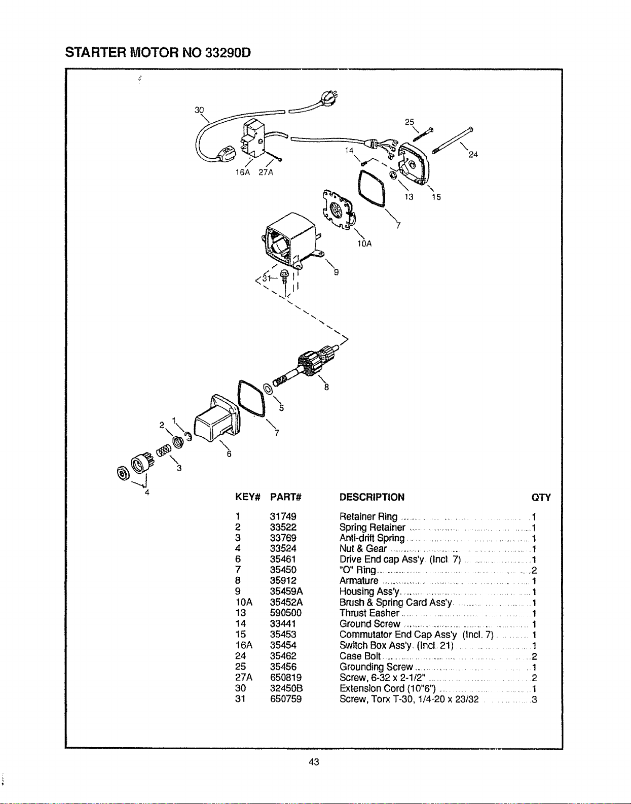
STARTER MOTOR NO 33290D
3\
4
<3_gL'_,_ tr 9
"- !l=
\
5
7
\
8
KEY# PART# DESCRIPTION
1 31749
2 33522
3 33769
4 33524
6 35461
7 35450
8 35912
9 35459A
10A 35452A
13 590500
14 33441
15 35453
16A 35454
24 35462
25 35456
27A 650819
30 32450B
31 650759
QTY
Retainer Ring ................................... 1
Spring Retainer ............................................ 1
Anti-drift Spring........................................ 1
Nut & Gear ........................................................1
Drive End cap Ass'y, (lncl 7) ..............................1
"O" Ring ..............................................................2
Armature ............................................................ 1
Housing Ass'y ................................................ 1
Brush & Spring Card Ass'y ............................. 1
Thrust Easher ................................................ 1
Ground Screw ..........................................................1
Commutator End Cap Ass'y (IncL 7) ........... 1
Switch Box Ass'y, (tncl, 21) ................... 1
Case Bolt ...........................................................2
Grounding Screw .................................... t
Screw, 6-32 x 2-1/2 ..................................... 2
Extension Cord (10"6") ............................... 1
Screw, Torx T-30, 1/4-20 x 23t32 .............. 3
43
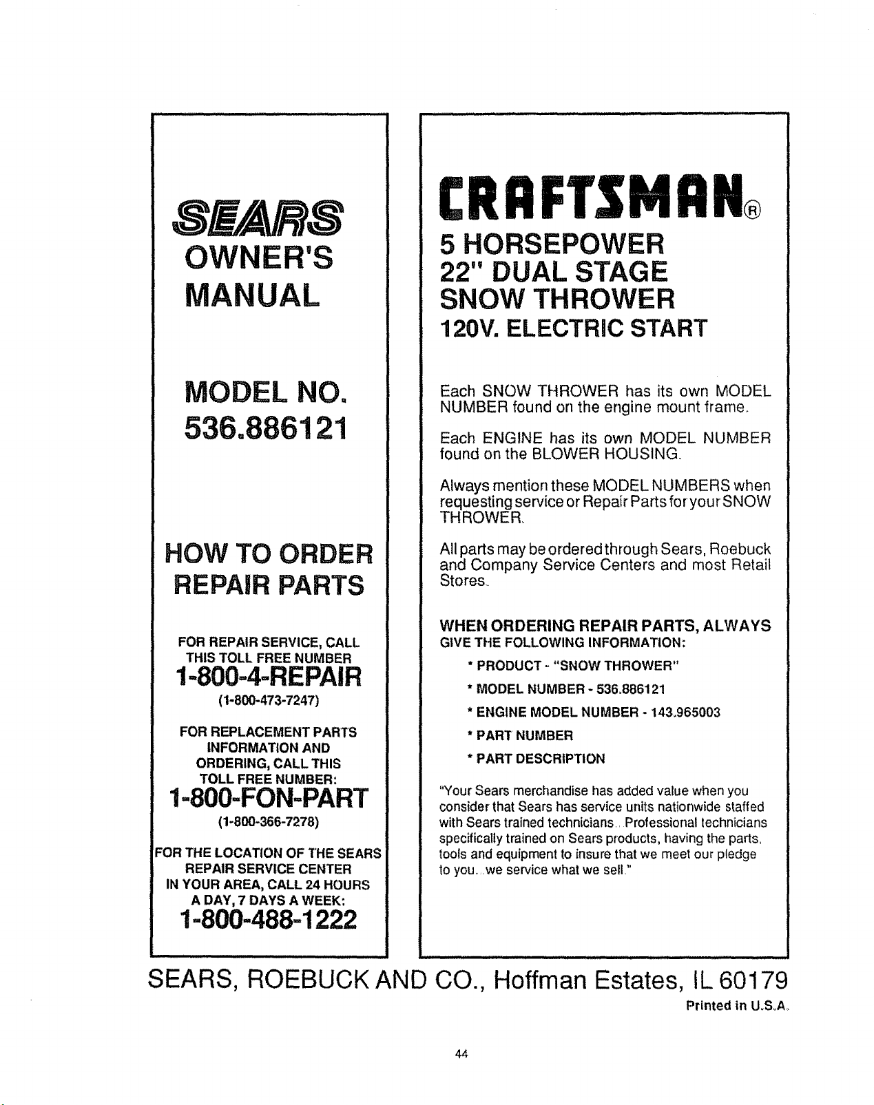
OWNER'S
MANUAL
MODEL NO.
536,886121
HOW TO ORDER
REPAIR PARTS
FOR REPAIR SERVICE, CALL
THIS TOLL FREE NUMBER
1-800-4-REPAIR
(1-800-473-7247)
FOR REPLACEMENT PARTS
INFORMATION AND
ORDERING, CALL THIS
TOLL FREE NUMBER:
I=800-FON-PART
(1-800-366-7278)
FOR THE LOCATION OF THE SEARS
REPAIR SERVICE CENTER
IN YOUR AREA, CALL 24 HOURS
A DAY, 7 DAYS A WEEK:
1=800-488-1222
SEARS, ROEBUCK AND CO.,
CRRFTSMRN®
5 HORSEPOWER
22" DUAL STAGE
SNOW THROWER
120V. ELECTRIC START
Each SNOW THROWER has its own MODEL
NUMBER found on the engine mount frame..
Each ENGINE has its own MODEL NUMBER
found on the BLOWER HOUSING.
Always mention these MODEL NUMBERS when
requesting service or Repair Parts foryourSNOW
THROWER.
All parts may be ordered through Sears, Roebuck
and Company Service Centers and most Retail
Stores.
WHEN ORDERING REPAIR PARTS, ALWAYS
GIVE THE FOLLOWING INFORMATION:
* PRODUCT o "SNOW THROWER"
* MODEL NUMBER - 536.886121
* ENGINE MODEL NUMBER - 143.965003
* PART NUMBER
* PART DESCRIPTION
"Your Sears merchandise has added value when you
consider that Sears has service units nationwide staffed
with Sears trained technicians., Professional technicians
specifically trained on Sears products, having the parts,
tools and equipment to insure that we meet our pledge
to you.,,we service what we sell,"
Hoffman Estates, IL 60179
Printed in U_SoA.
44
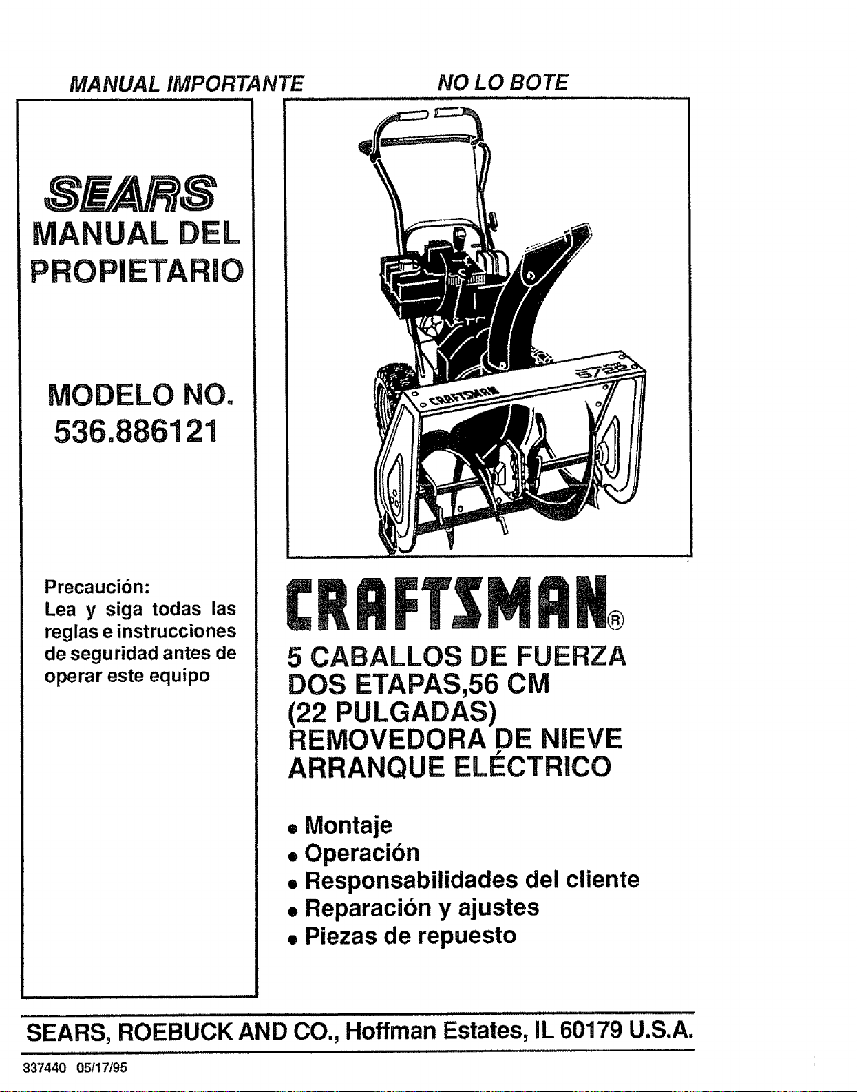
MANUAL IMPORTANTE NO LO BOTE
MA AL DEL
PROPIETA
MODELO NO.
536 ;121
Precaucion:
Lea y siga todas las
reglas e instrucciones
de seguridad antes de
operar este equipo
5 CABALLOS DE FUERZA
DOS ETAPAS,56 CM
(22 PULGADAS)
REMOVEDORA DE NIEVE
r
ARRANQUE ELECTRICO
• Montaje
• Operacion
• Responsabilidades del cliente
• Reparacion y ajustes
• Piezas de repuesto
SEARS, ROEBUCK AND CO., Hoffman Estates, IL 60179 U.S.A.
337440 05/17/95
iiiii
REGLAS DE SEGURIDAD
ii/1/1_1/i ............. ii
PRECAUCION: SIEMPRE DESCONECTE EL ALAMBRE DE LA BUJIA
Y COLOQUELO DONDE NO HAGA CONTACTO CON L BUJIA PARA
EVITAR UN ARRANQUE ACCIDENTAL AL MONTAR,
TRANSPORTAR, AJUSTAR O EFECTUAR REPARACIONES+
IMPORTANTE
LOS ESTANDARES DE SUGURIDAD REQUIEREN LA PRESENCIA DEL OPERADOR EN LOS
CONTROLES PARA MINIMIZAR EL RIESGO DE HERIDAS. SU REMOVERDORA DE NIEVE
ESTA EQUIPADA CON DICHOS CONTROLES. NO INTENTE PASAR POR ALTO LA FUNCION
DEL CONTROL DE PRESENCIA DEL OPERADOR BAJO NINGUNA CIRCUNSTANCIA
CAPACITACION
1. Lea el manual del operador cuidadosamente,
Famlllarlcasecompletamentecon los controles
y el uso apropisdo de la removedorade nleve. Sepa
calmsdetenerla removedoradenleveydesenganchar
los controlea r_pldsmente.
2. Nunca permlta a nltiossparer la removedorade
nleve y mant6ngalos fuera del alcance de la mtsma
mlentraa se encuentraan operacl6n, Nunca permlta
qua aduitos operen ia removedora de nteve sin
Instrucol6n aproplada. No Ileve pasaJeros.
3. Mantenga el drea Itbre de personas, especlalmente
n!tiospaquenosy mascotas,
4o Tenga precauci6na fin de evitardesltzamlentos
o caldas, especlalmenteal operar la removedora
de nleve en retroceso.
PREPARAClON
1. Inspecclone completamente el drea donde se usard la
removedora de nleve y retire lodes las esteras, trineos,
tableros, alambres, y otros obJetos extrafios.
2. Desenganche todos los embragues y camblea neutro
antes de arrancar el motor.
3+
Nooperala removedoradenlevesinvesttrlasprendas
de Invlerno adecuedas para amblentes exterlores,
Vistacatzadoqua meJoresuestabtlldadensuperficies
llsas.
4, ManeJeel combustible con cutdado; es altamente
Inflamable,
(a) Use un contenedor para combustible
aprobado.
(b) Nunca retire la tapadera del tanque de com-
bustibleo afiadacombustibleaun motor en
marchao a un motor caltente+
(c) Uene el tanque para combustible al airs Itbre,
con culdado extremo. Nunca liens el tanque
en amblentes Interiores.
(d) Coloque nuevamente la tapadera det tanque
para combustible de manera segura y Ilmpie
el combustible derramado=
(e) Nunca almacane combustible o la
tanqua dentro de un edtficto donde los
vapores pudlesen entrar en contacts con
una llama desproteglda o una chlspa+
(f) Verlfique las existenclas de combustible an-
tes de cads uso, permltfendo espaclo para
expansl6n puesto que el calor del motor y/o
el sol pueden causar la expanstbn del com-
bustible.
5. Use cables de extensl6n y recept_culos de la
manera especiflcada por el fabrlcante para todas
las removedoras de nieve con restores
acclonados pot energla el_ctrlca o restores de
arranque el_ctrico.
6. AJuste la attura de la removedora de nteve pare pasar
sobre superficies de gravao pledra triturada_
7. Jamds Intente efectuar ntngt3n ajuste mlentras el mo-
tor se encuentra en marcha (excepts cuando el
fabrlcante Io recomlende as(especificamente).
8+
9+
Permita qua el motor y la removedora de nleve se
ajusten alas temperaturas exterlores antes de
comenzar a rettrar la nleve+
Slempre use gafas de segurtdad o protectores para
los oJos durante la operaclbn o mlentras se efect+a un
ajuste o reparaclbn para proteger sus ojos de objetos
extrafios qua pudlesen ser lanzados pot la removedora
de nleve+
OPERACION
1. No coloque las manoso los pies cerca o bajo plezas
rotatlvas. Mantdngase a dtstancta de la abertura para
descarga todo el tlempo+
2. Tenga precaucl6n extreme al operar sobre o al cruzar
caminos, scares, o callas de grave Mant_ngase alerta
en caso de pellgros ocultos o trdflco.
3. Despu6s de golpear un objeto extraSo, pare et motor,
retire el alambre de fa bujla, desconecte el cable en
restores eldctrlcos, tnspecclone completamente la
removedora de nleve a fin de encontrar cualquier
dafio, y reparar dtcho daSo antes de arrancar y operar
la removedora de nteve nuevamente+
4+ En et caso de qua la removedora de nleve comlence a
v|brar fuera de Is normal, pare el motor y revise la
mdqulna lnmedtatamente para encontrar la causa+
Generalmente, la vibrac[6n esuna advertencia de
problemas+
5+ Pare el motor dondequiera que deje la posici6n de
op_raci_n, ,3ntis d_ d_sobstruir _ _.!oj_mi_.qto de+
barrenolpropulsor ogufa de descarga, y cuando areolae
cualesqutera reparactones, ajustes, o inspecclones
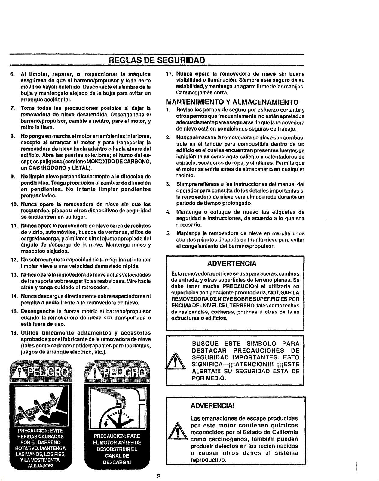
...........................REGLAS DE SEGuRIDAD .....
6o A! limplar, reparar, o Inspecctonar Is mdqulna
asegdrese de qua el barrenolpropulsor y toda parts
m6vll se hayan dstenido. Desconecte el alambre de la
buJla y mantdngalo alejado de la buJia pare eviler un
arranque accidental,
7. Tome todas ias precauclones poslbles al deJar la
removedors de nleve desatendtda. Desenganche el
barrenolpropulsor, cambte a neutro, pare et motor, y
retire la gave.
8. Nopongaan marchaelmotor enamblentesinterlores,
excepto al arrancar el motor y para transportar la
removedorade nlevehaoleadentroo haclaaluera del
adiflclo.Abra las puertas exteriores;el humodel es-
capeespallgroso(contleneMONOXIDODECARBONO,
un GAS INODOROy LETAL)o
9. NoItmplenlave perpendicularmenteala dfrecclbnde
pendlentes.Tengepracauci6natcamblar dedlrecci6n
an pendlentes. No intents itmpiar pendlentes
pronuncladas.
10. Nunca opera la removedora de nteve sin qua los
resguardos,placesu otrosdlsposltlvosde seguridad
soencuentren en su lugar.
11. Nuncaopere la removedora de nleve cerca de reclntos
de vldrio, autombviles, huecos de ventanas, sltlos de
carga/descarga, y simllares sin el ajuste aproplado del
dngulo de descarga de la nleve. Mantenga ntfios y
mascotas sleJados.
12. No sobrecargue la capacldad de la mdqulna al lntentar
Ilmptar nteve a una velocidad demastado rdpida.
13. Nunca opera taremovadora de nleve a altasvetocldades
de transports sobre superficies resbalosas. Mire hacla
atrds y tangs cuidado al retroceder.
14. Nunca dascargue dlrectamente sobre espectadores nl
permtta a nadle frente a [a removedora de nleve.
15. Desenganche la fuerza motriz al barreno/propulsor
cuando la ramovedora de nteve sea transportada o
est_ fuera de use.
16. Uttiice t_nicamente aditamentos y accesorlos
aprobados per elfabrlcante de ta removedora de nleve
(tales come cadenas antlderrapantes para las llantas,
juegos de arranque eldctrtco, etc.)°
17. Nunca opera la removedora de nteve sin buena
visib|lldad o Iiumlnaclbno S[empre est_ seguro de su
estabittdad, y mantenga un agar re firms de fasmanijas.
Camlne; Jam_,scorra.
MANTENIMIENTO Y ALMACENAMIENTO
1,, Revise los pernos de seguro per esfuerzo cortante y
otros pernos quo frecuentemente no estdn apretados
adecuadamente pare asegurarse de que la removedora
de nleve astd en condlctones seguras de trabaJo,_
2. Nunca almacane la removedora de ntevecon combus-
tibia an el tanque para combustible dentro de un
edificlo en el cual se encuentran presentes fuentesde
tgnlci6n tales come agua callente y calentadores de
espaclo, secadoras de ropa, y similareso Permits que
el motor se enfrle antes de almacenarlo en cualquter
reclnto.
3_
Siempre refl6rase alas ]nstrucclones dal manual de|
operador para consulta de los detatles tmportantes sl
la removedora de nieve serd almacenada durante un
per[ode de ttempo prolongado.
4. Mantenga o coloque de nuevo las etlquetas de
sagurldad e tnstrucclones, de acuerdo a Io qua sea
necesarlo.
5. Mantenga la removedora de nieve en marcha unos
cuantos minutes despu_s de tirar la nfeve para evitar
e! congelamlento del barrenofpropulsor.
ADVERTENCIA
Esta removedora de nieve se usa pare aceras, camtnos
de entrada, y otras superficies de terrano planes. Se
debe tener mucha PRECAUCION al utiltzarla en
superficies con pendiente pronunciada, NO USAR LA
REMOVEDORA DE NIEVE SOBRE SUPERFICIES POR
ENCIMA DELNIVEL DELTERRENO, tales come laches
de resldenc|as, cocheras, porches u otras de tales
estructuras o edlficlos.
BUSQUE ESTE SIMBOLO PARA
DESTACAR PRECAUCIONES DE
SEGURIDAD IMPORTANTES, ESTO
SIGNIFICAwiiiATENCION !! ! itiESTE
ALERTA!!! SU SEGURIDAD ESTA DE
POR MEDIOo
ADVERENCIA!
Las emanaciones de escape productdas
per este motor contienen quimicos
reconocldos per el Estado de California
come carcinbgenos, tambidn pueden
produeir defectos en los recidn nacidos
o causar otros dar_os al sistema
reproductive.
i
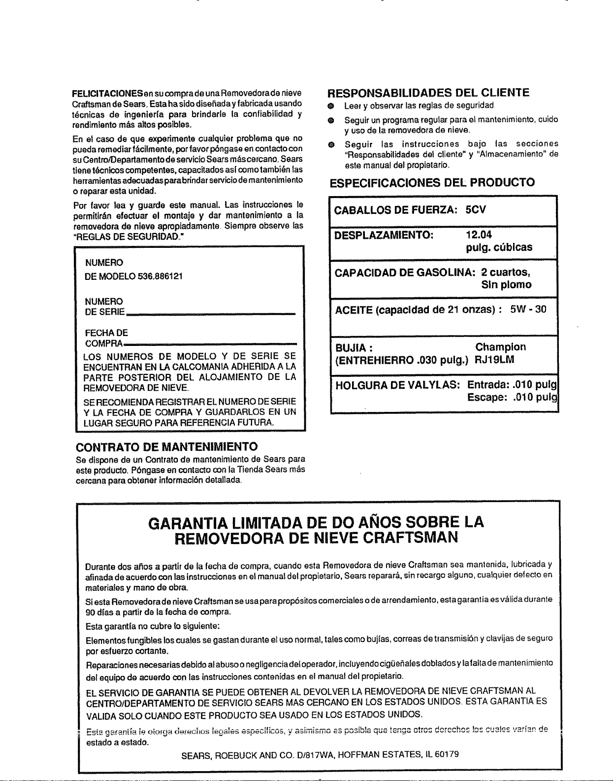
FELICITACIONES ensu comprade una Removedorade nieve
Craftsman de Sears° Esta ha sidodisehaday fabricada usando
t_cnicas de ingenier|a para brindarle la confiabilidad y
rendimiento m_s altos posible&
En et caso de que experimente oualquier probiema que no
pueda remedial f_cilmente, por favor p6ngase en contacto con
suCentroiDepartamento de servicioSears mAscercano. Sears
tiene t6cnicos competentes, capacitados as[ comotambi(_nIas
herramientasadecuadasparabrindar servicio de mantenimiento
o reparar esta unidado
Por favor lea y guarde este manual Las instrucciones le
permitir&n efectuar e! montaje y dar mantenimiento a la
removedora de nieve apropiadamente, Siempre observe las
"REGLAS DE SEGURtDAD.,"
NUMERO
DE MODELO53&886121
NUMERO
DE SERIE
FECHA DE
COMPRA ......................
LOS NUMEROS DE MODELO Y DE SERIE SE
ENCUENTRAN EN LA CALCOMANIA ADHERtDA A LA
PARTE POSTERIOR DEL ALOJAMIENTO DE LA
REMOVEDORA DE NIEVEo
SE RECOMIENDA REGISTRAR EL NUMERO DE SERtE
Y LA FECHA DE COMPRA Y GUARDARLOS EN UN
LUGAR SEGURO PAPA REFERENCIA FUTURA.
.................. n u i ull,lllllll
CONTRATO DE MANTENIMIENTO
Se dispone de un Contrato de mantenimiento de Sears para
este producto,Pbngase en contacto con la Tienda Sears m_s
cercana para obtener inlormaci6n detailada
RESPONSABILIDADES DEL CLIENTE
® Leer y obsercar las reglas de seguridad
® Seguir un programa regular para el mantenimiento, cuido
y uso de la removedora de nieve°
O Seguir las instrucciones bajo las secciones
"Responsabilidades de1 cliente" y "Atmacenamiento" de
este manual del propietario..
ESPECIFICACIONES DEL PRODUCTO
CABALLOS DE FUERZA: 5CV
DESPLAZAMIENTO: 12.04
pulg. cdblcas
CAPACIDAD DE GASOLINA: 2 cuartos,
Sin plomo
ACEITE (capacldad de 21 onzas) : 5W - 30
BUJIA : Champion
(ENTREHIERRO .030 pulg.) RJ19LM
HOLGURA DE VALYLAS: Entrada: .010 pulg
Escape: .010 puig
GARANTIA LIMITADA DE DO A ',IOS SOBRE LA
REMOVEDORA DE NIEVE CRAFTSMAN
Durante dos athosa partir de la fecha de compra, cuando esta Removedora de nieve Craftsman sea mantenida, lubricada y
afinada de acuerdo con las instruccionesen el manual del propietario, Sears reparar&, sin recargo alguno, cualquier defecto en
materia!es y mano de obr&
Siesta Removedorade nieve Craftsman se usa para prop6sitoscomerciales o de arrendamiento, esta gar antia es v&lida dutanle
90 d[as a part# de la fecha de compr&
Esta garantia no cubre lo siguiente:
Elementos fungibleslos cuales se gastan durante el uso normal, tales como bujias, correas de transmisi6n y clavijas de seguro
por esfuerzo cortante.
Reparaciones necesarias debldo at abuso o negligencia det operador, incluyendo cigiJeSales dobiadosy iafafta de mantenimien!o
de! equipo de acuerdo con las instruccionescontenidas en el manual del propietario.
EL SERVlCIO DE GARANTIA SE PUEDE OBTENER AL DEVOLVER LA REMOVEDORA DE NIEVE CRAFTSMAN AL
CENTRO/DEPARTAMENTO DE SERVIC!O SEARS MAS CERCANO EN LOS ESTADOS UNIDOS ESTA GARANTIA ES
VALtDA SOLO CUANDO ESTE PRODUCTO SEA USADO EN LOS ESTADOS UNIDOS..
Es_ gara,ni{a. ie oio_ga oerecf_os e_jatu_ u=c,_uI,,co=,y asimismo as T^-_" - ,_r,_, ot,,_, d.... h_ _o....... vari_n de
estado a estado.
SEARS, ROEBUCK AND CO.. Dt817WA, HOFFMAN ESTATES, IL 60179
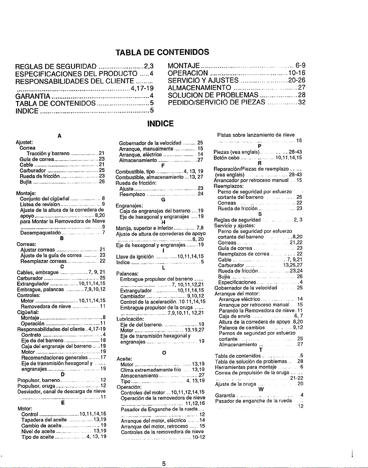
TABLA DE CONTENIDOS
REGLAS DE SEGUR1DAD ........................ 2,3
ESPECIFICACtONES DEL PRODUCTO ..... 4
RESPONSABILIDADES DEL CLIENTE ..........
............................................................. 4,17-19
GARANTIA ..................................................... 4
TABLA DE CONTENIDOS ............................... 5
INDICE ............................................................. 5
MONTAJE ...............................................................6-9
OPERACION ............................................ 10-16
SERVICIO Y AJUSTES ................................20-26
ALMACENAMIENTO ...........................................27
SOLUCtON DE PROBLEMAS .......................28
PEDIDO/SERVICIO DE PtEZAS .........................32
INDICE
A
Ajustet:
Correa
Tracci6n y barreno ........................21
Gu[a de correa ..........................................23
Cable ................................................ 21
Oarburador .............................................25
Rueda de fricci6n ....................................23
Bujfa .........................................................26
Montaje:
Conjunto del cig0efial ............................8
Ltstea de revision......................................9
Ajuste de la attura do la corredera de
apoyo ....................................................8,20
para Montar la Removedora do Nieve
Desempaquetado .............................. 7
B
Correas:
Ajustar correas ...........................................21
Ajuste de la gu[a de correa ...............23
Reemplazar correas ..............................22
C
Cables, embrague ........................7, 9, 21
Carburador ..................................................25
Extrangulador .......................t0,11,14,15
Embrague, palancas ...................7,9,10,12
Controles:
Motor .................................I0,11,14,15
Removedora de nieve .........................11
CigGefial:
Montaje ......................................................8
Operaci6n..........................................11
Responsabilidades del cliente o4,17-19
Contrato .....................................................4
Eje de del barreno ...............................18
Caja del engranaje del barreno .......19
Motor ............................................................19
Recomendaciones generates ..........17
Eje de transmisi6n hexagonal y ........
engranajes...o..............................................19
D
Proputsor, barreno ...................................12
Proputsor, oruga ....................................12
Desviador, canal de descarga de nieve
........................ ,.................. ,., ............... . .......... ...... 1 t
E
Motor:
Control .................................10,11,I4o15
Tapadera del aceite .........................13,19
Cambio de aceite .........................................!9
Nivel de aceite .................................13,19
Tipo de aceite ...............................4, 13, 19
Gobernador de la velocidad ..........25
Arranque, manualmente .......................15
Arranque, ei6ctrico ............................14
Almacenamiento ..............................27
F
Combustible, tipo .................... 4, 13, 19
Combustible, almacenamiento .._13, 27
Rueda de fricci6n:
Ajuste ......................................................23
Reempiazo ............................................24
G
Engranajes:
Caja de engranajes del barreno .... !9
Eje do hexagonal y engranajes ..... 19
H
Manija, superior e inferior.....................7,8
Ajuste de aftura de correderas de apoyo
............................................................................8, 20
Eje de hexagonal y engranajes ..........19
!
Llave de ignici6n ...................10,I 1,14015
Indice......................................................5
L
Palancas:
Embrague proputsor del barreno .........
.........................................7, 10,11,t2,21
Extrangulador ....................10,11,14,15
Cambiador ......................................9,10,12
Control de la aceleraci6n...10.11,14,15
Embrague propulsorde la oruga ........
.................................................7,9,10,11, 12,21
Lubricaci6n:
Eje de del barreno ............................18
Motor ...........................................13,19,27
Eje de transmisi6n hexagonal y
engranajes ............................................19
O
Aceite:
Motor ................................................13,19
Clima extremadamente frio ..... 13,19
Almacenamiento.............................27
Tipo ...............................................4. 13,19
Operaci6n:
Controles del motor ... 10,11,12,14,15
Operaci6n de la removedora de nieve
..........................................................11,12,16
Pasador de Enganche de la rueda ......
..................................................................12
Arranque del motor, el_ctrico ..........14
Arranque del motor, retroceso ....... 15
Controles de la removedora de nieve
.............................................................I0-12
Pistas sobre lanzamiento de nieve
..................................................... 16
P
Piezas (vea englais) ......................28-43
Bot6n cebo ............................I0,11,14,15
R
Reparacibn/Piezas de reemplazo ........
(yea englais) ...................................28-43
Arrancador pot retroceso manual .. 15
Reemplazos:
Perno de seguridad por esfuerzo
cortante del barreno ................... 25
Correas ............................... 22
Rueda do friccibn .................... 23
S
Reglas de seguridad ............... 2, 3
Servicio y ajustes:
Perno de seguridad pot esiuerzo
cortante del barreno .............. 8,20
Correas ............................... 21,22
Gu[a de correa ........................... 23
Reemptazos de correa ............... 22
Cable ................................. 7, 9,21
Carburador ......................... 13,25,27
Rueda de fdcci6n ...................... 23,24
Bujia ................................................. 26
Especificaciones ............................ 4
Gobernador de la velocidad ......... 25
Arranque del motor:
Arranque el_ctrico .......................... 14
Arranque por retroceso manual .....15
Parando la Removedora de nieve. 11
Caja de envio ............................. 6, 7
Altura de la corredera de apoyo 8,20
Patanca de cambios ................. 9,12
Pernos de seguridad por estuerzo
cortante ............................. 25
Almacenamiento ................ 27
T
Tabla de contenidos ................... 5
Tabla de soluci6n de problemas ..... 28
Herramientas para montaje ................ 6
Correa de propulsi6n de la oruga .........
........................................ 21-22
Ajuste do la oruga ............ 20
W
Garantia ......................................... 4
Pasador de enganche de la rueda ....
...................... 12
5
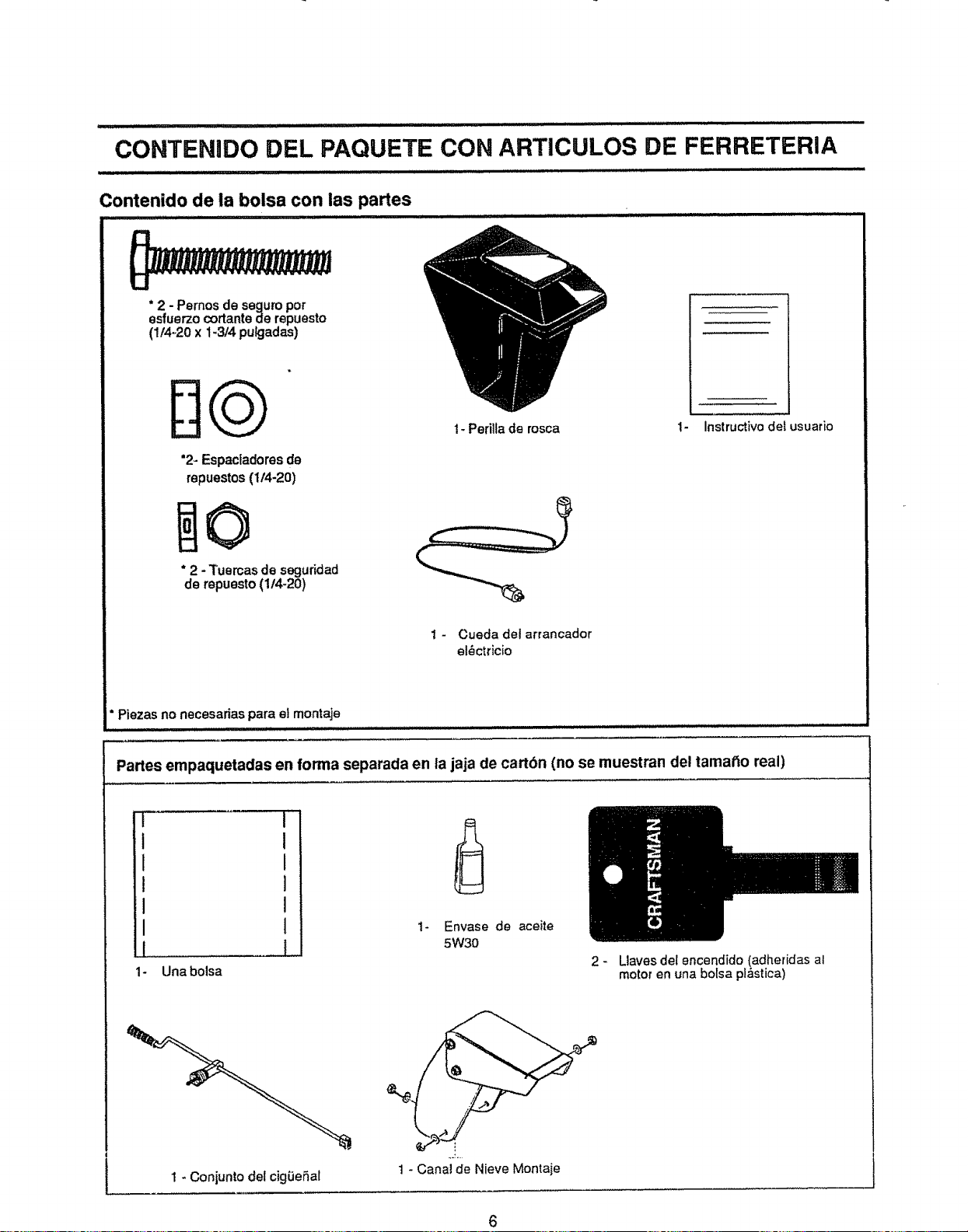
................ ii , _ ill i i iilllli, i
CONTENIDO DEL PAQUETE CON ARTICULOS
DE FERRETERIA
Contenido de la bolsa con ias partes
* 2 - Pernos de seguro por
esfuerzo cortante de repuesto
(1/4-20 x 1-3/4 pulgadas)
DQ
"2- Espaciadores de
repuestos (114-20)
0
* 2 - Tuercas de seguridad
de repuesto (1f4_20)
1- PeriUade rosca
t - Cueda del arrancador
el_ctricio
1- Instructivo del usuario
° Piezas no necesarias para et montaje
i
Partes empaquetadas en forma separada en la jaja de cart6n (no se muestran del tamat_o real)
I
1
!
I
I
I .............
1- Unabolsa
__L
Envase de aceite
5W30
2_ Llaves del er_cendido(adheridas al
motor en una bolsa p!_fistica)
1 _ Conjunto del cigL_eSal
1 * Canal de Nieve Montaje
6
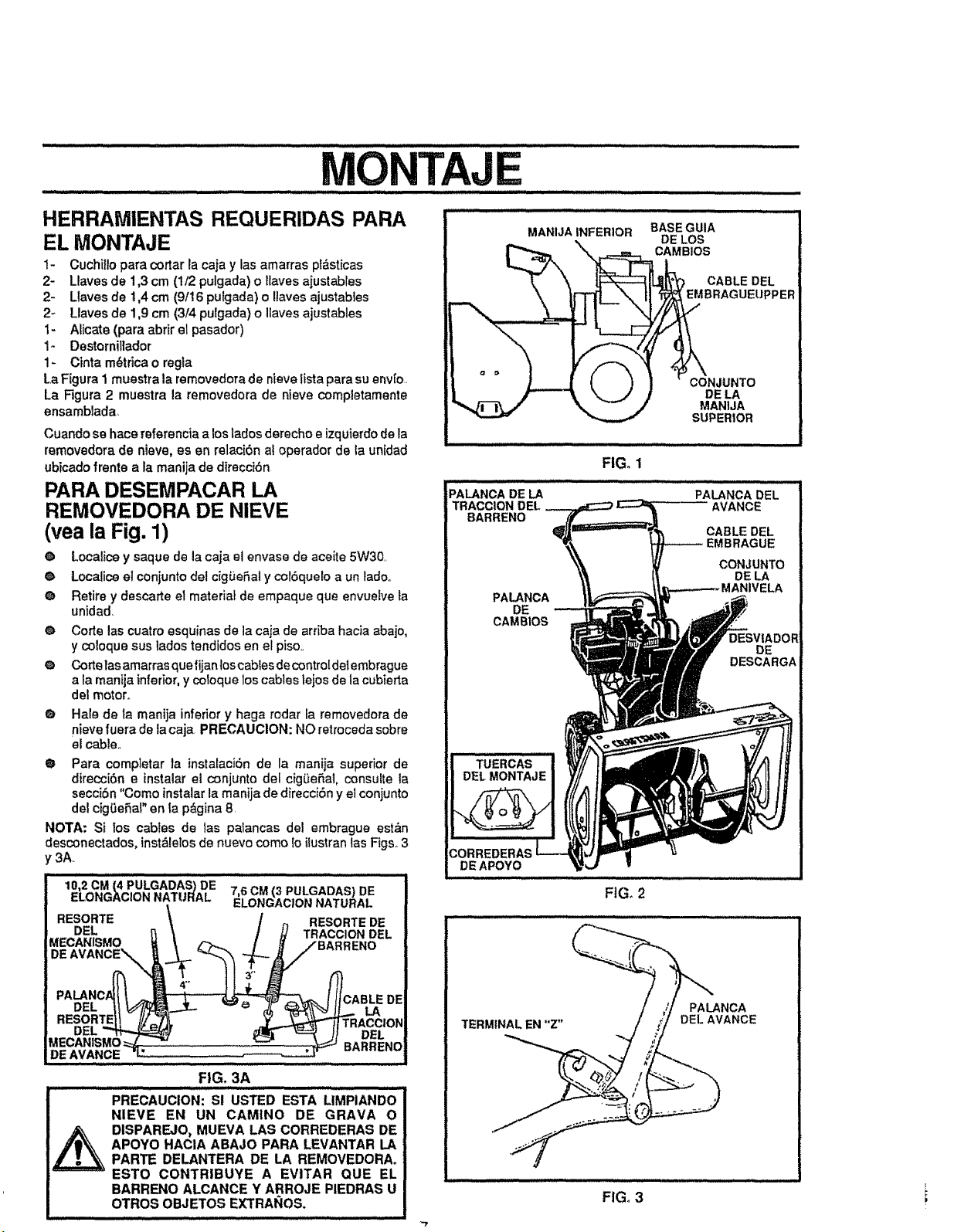
TAJE
ii i,i ,._
HERRAIVIENTAS REQUERIDAS PARA
EL MONTAJE
1- Cuchilo para cortar la caja y las amarras pt_sticas
2- Llaves de 1,3 cm (1/2 pulgada) o laves aiustables
2- Llaves de t,4 cm (9116pulgada) o laves ajustables
2_ Llaves de 1,9 cm (314 pu?gada) o laves ajustables
I- Afcate (para abrir el pasador)
I- Destornilador
1- Cinta m6trica o regla
La Figura 1 muestra la removedora de nieve lsta para su env[o.
La Figura 2 muestra la removedora de nieve compietamente
ensambiada
Cuando se hace referenciaa los lados derecho e izquierdode la
removedora de nieve, es en relaci6n al operador de la unidad
ubtcado frente a la manija de direcci6n
PARA DESEMPACAR LA
REMOVEDORA DE NIEVE
(vea la Fig, 1)
Q Localce y saque de la caja el envase de aceite 5W30.
@ Locafce el conjunto del cigie6al y col6quelo a un ladoo
@ Retire y descarte el materiat de empaque que envueive ia
unidad.
@ Code las cuatro esquinas de la caja de arriba hacia abajo,
y co!oque sue lados tendidos en et piso..
@ Corte lasamarras quefijanlos cabtes de contro[delembrague
a la manija inferior,y coloque los cables lejos de ta cubieda
del motor.
O Hale de la manija inferior y haga rodar ta removedora de
nieve fuera de ta caja. PRECAUCION: NO retroceda sobre
el cable..
O Para comp]etar la instalaci6n de ta manija superior de
direcci6n e instalar el conjunto def cigie6al, consulte ta
secci6n "Como instalar la manija de direcci6n y el conjunto
del cigGe6al" en ta p_gina 8.
NOTA: Si los cables de tas patancas del embrague est_,n
desconectados, inst&lelosde nuevo como lo ilustrantas Figs. 3
_3A.
10'2cM€.PULGADAS_DE 7,6C.<3.ULGADASlDE
ELONGACIONNATURAL ELONGACIONNATURAL
RESORTE / _ RESORTEDE
DEL 1 / H TRACCIONDEL
MECANISMO U ,.">.._ / /# /BARRENO
C.......................
DEAVANCE .... ,.___._rr _=
FIG, 3A
TERMINAL EN "Z"
FIGo1
FIG. 2
CON JUNTO
DE LA
MANIJA
SUPERIOR
PALANCA DEL
AVANCE
CABLE DEL
_EMBRAGUE
CONJUNTO
DE LA
ELA
PALANCA
DELAVANCE
i
FIG. 3 i
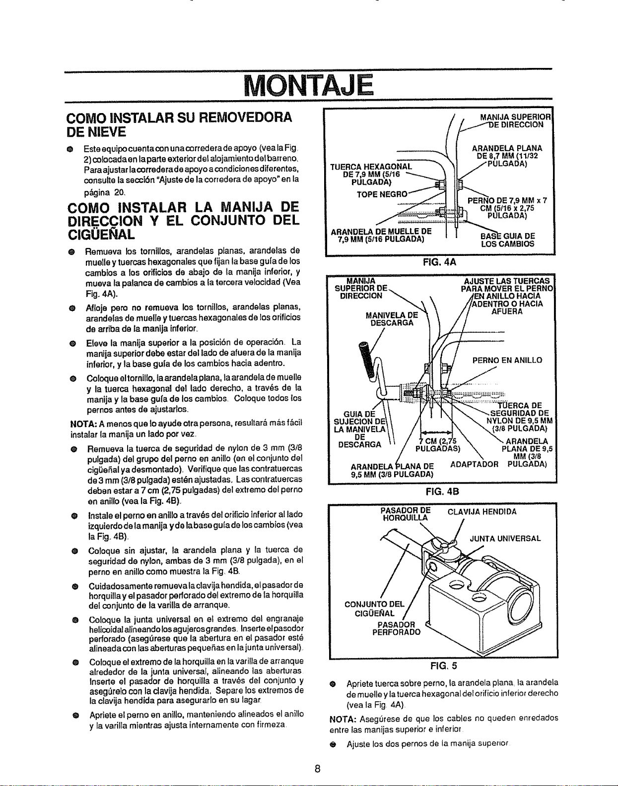
............... i i illll iil_i,iiii, i ,ill ii ii LI i iilllllllllllll illl_llll
MONTAJE
IIU,,I
MANIJASUPERIOR
COMe INSTALAR SU REMOVEDORA
DE NIEVE
@ Este equipo cuentacon unacorredera de apoyo (vea la Fig
2) colocadaen laparte exteriordel atojamiento delbarreno.
Para ajustar lacorrederade apoyo a condicionesdiferentes,
consutteta secci6n "Ajuste de la corredera de apoyo" en la
p&gina 20,
COMe INSTALAR LA MANIJA DE
DIRECCION Y EL CONJUNTO DEL
CIGOEI AL
@ Remueva los tornillos, arandalas planas, arandelas de
muelley tuercas hexagonales que fijan ta base gu[a de los
cambios a los orificios de abajo de {a manija inferior, y
mueva la palanca de cambios ata tercera velocidad (Vea
Fig. 4A).
O Afloje pero no remueva los tornillos, arandelas planas,
arandelas de muelle ytuercas hexagonales de losorificios
de arriba de la mantja inferior_
e Eleve la manija superior ala posicibn de operacibn.. La
manija superiordebe estardel tado de afuera de la manija
inferior, y la base guia de los cambios hacia adentro.
@ Coloque eltornillo, la arandelaplana, la arandela de muefle
y la tuerca hexagonal del lade derecho, a tray,s de la
manija y la base gul'ade los cambios Coloque redes los
pernos antes de ajustarlos..
NOTA: A menos que 1oayude otra persona, resuitar_ m&s f&cit
instalarla manija un lade per vez.
• Remueva la tuema de seguridad de nylon de 3 mm (3f8
pufgada) del grupo del perno en anillo (en el conjunto del
cig0eSalyadesmontado), Verifiqueque lascontratuercas
de 3 mm(3/8 pulgada) estdn ajustadas_Las contratuercas
deben ester a 7 cm (2,75 pulgadas) del extreme del perno
en anillo (yea la Fig. 4B)_
@ tnstale el pemo en aniffoa trav_s del orificioinferior al lade
izquierdode la manija yale labase gufade loscambios(yea
la Fig. 4B)..
• Coloque sin ajustar, Is arandela plana y la tuerca de
seguridad de nylon, ambas de 3 mm (3t8 pulgada), en el
perno en anillo como muestra la Fig 4B.
® Cuidadosamente remuevalaclavija hendida, efpasador de
horquilla y el pasador peffotado del extremo de Ia horquilla
de_conjunto de la varitla de arranque_
@ Coloque la junta universal en el extremo det engranaje
helicoidal alineando los agujeros grandee Inserte efpasodor
perforado (aseg_rese que la abertura en et pasador est_
afineada con las aberturas peque_.as en lajunta universal)..
® Coloque el extremo de la horquitla en la varitla de arranque
alrededor de la junta universal, a]ineando tas abertutas
lnserte el pasador de horquiJla a tray,s del conjunto y
aseg0relo con la clavija hendida. Separe los extremos de
la clavija hendida para asegurarlo en su lager
@ Apriete el perno en anillo, manteniendo alineados el aniI_o
y la varitra mientras ajusta internamente con firmeza.
TUERCA HEXAGONAL
DE 7,9 MM (5/16
PULGADA)
TOPE
ARANDELA DEMUELLE DE
7,9MM (5116PULGADA)
ARANDELA PLANA
DE 8,7 MM (11/32
7,9 MM x 7
CM (5t16 x 2,75
PULGADA)
GUIA DE
LOS CAMBIOS
FIG, 4A
ii illll,i
MANIJA
SUPERIOR DE.,,.
DIRECCION
MANIVELADE
DESCARGA t
AJUSTE LASTUERCAS
PARAMOVEREL PERNO
O HACIA
AFUERA
PERNO EN ANILLO
GUIA DE
SUJECION DE
LA MANIVELA
DE
DESCARGA
ARANDELA DE
9,5 MM (3/8 PULGADA)
...............TUERCA DE
DE
NYLON DE 9,5 MM
'3/8 PULGADA)
ARANDELA
PLANA DE 9,5
MM (3/8
ADAPTADOR PULGADA)
FIG. 4B
PASADORDE CLAVIJAHEND1DA
HOROUILLA
JUNTA UNIVERSAL
CONJUNTO DEL
CIGOE_AL
PASADOR
PERFORADO
FIG, 5
® Aprietetuerca sobre perno, la arandela ptana, la arandeta
de muelle yla tuerca hexagonaldelorificio inferior derecho
(yea ta Fig. 4A)
NOTA: Asegerese de que los cables no queden enredados
entre tas manijas superior e inferior
@ Ajuste los dos pernos de la manija superior
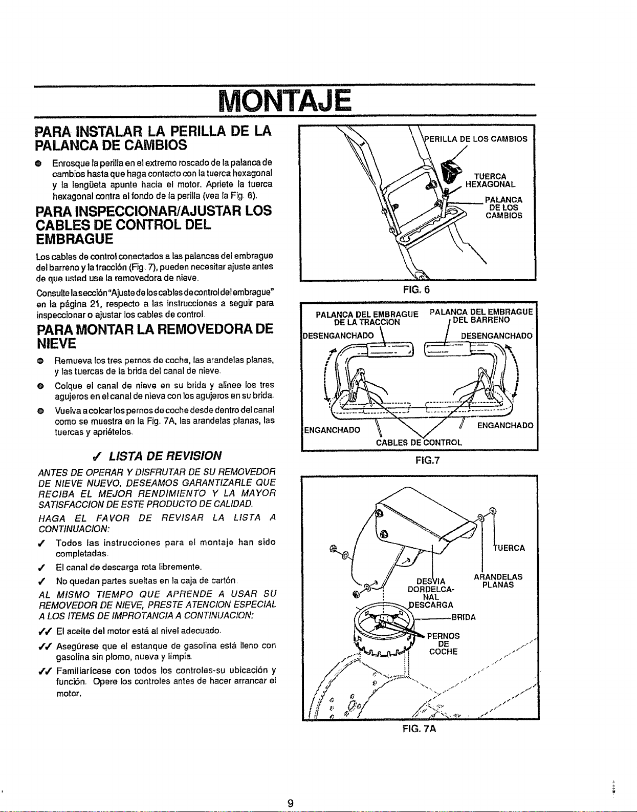
MONTAJE
PARA INSTALAR LA PERILLA DE LA
PALANCA DE CAIVIBIOS
® Enrosque la perilla en el extremo roscadode la palanca de
cambtos hasta que haga contactoconla tuerca hexagonal
y la leng_eta apunte hacia el motor° Apriete la tuerca
hexagonal contra el rondo de la perilla (vea !a Fig 6).
PARA INSPECCIONAR/AJUSTAR LOS
CABLES DE CONTROL DEL
EMBRAGUE
Los cables de control conectados a taspalancas det embrague
del barreno y la tracciSn (Fig 7), pueden necesitar ajuste antes
de que usted use la removedora de nieve..
Consult® laseccibn"Ajuste de k)scabtes de control de!embrague"
en ta p&gina 2t, respecto a 1as instrucciones a seguir para
inspeccionar o ajustar los cables de control.
PARA MONTAR LA REMOVEDORA DE
NIEVE
® Remueva {ostres pemos de coche, ias arandelas ptanas,
y tas tuercas de la brida del canal de nieve.
® Colque el canal de nieve en su brida y a{inee los tres
agujeros en e! cana! de nieva con los agujeros en su brida_
® Vuelva acolcar lospernos de coche desde dentro del canal
como se muestra en la Fig_7A, las arandelas planas, las
tuercas y apri_telos_
#" LISTA DE REVISION
ANTES DE OPERAR Y DtSFRUTAR DE SU REMOVEDOR
DE NIEVE NUEVO, DESEAMOS GARANTIZARLE QUE
RECIBA EL MEJOR RENDIMIENTO Y LA MAYOR
SA TISFACCION DE ESTE PRODUCTO DE CALIDAD..
HAGA EL FAVOR DE REVlSAR LA LISTA A
CONTtNUACION:
/ Todos tas instrucciones para el montaje ban sido
completadas
/ El canal de descarga rota libremente,.
/ No quedan partes suettas en la caja de cartSn.
AL MISMO TIEMPO QUE APRENDE A USAR SU
REMOVEDOR DE NIEVE, PFIESTE A TENCION ESPECIAL
A LOS ITEMS DE IMPROTANCIA A CONTINUACION:
v"/ El ace!t®del motor est_ al nivel adecuado_
// AsegSrese que el estanque de gasolina est& lleno con
gasolina sin plomo, nueva y limpia
,t'J' Familiarlcese con todos los controles-su ubicaciSn y
funciSn. Opere los controles antes de hacer arrancar el
motor,
FIG_6
PALANCA DEL EMBRAGUE
DE LA TRACCION
DESENGANCHADO \\
i ii ii i LII
PALANCADELEMBRAGUE
/DELBARRENO .
.........t DESENGANCHADO
CABLES DE CONTROL
,1,/i/iH I,L,
FIG.7
DORDELCA-
NAL
)ESCARGA
ARANDELAS
PLANAS
FIG, 7A
9
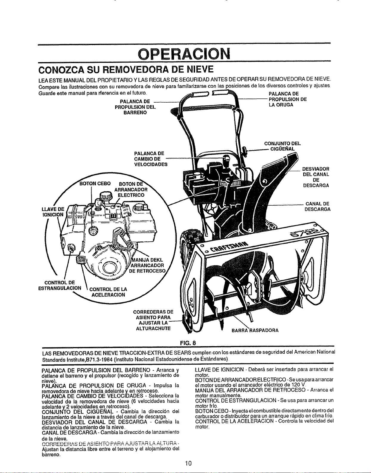
OPERACION
i
CONOZCA SU REMOVEDORA DE NIEVE
LEA ESTE MANUAL DEL PROPIETARIO Y LAS REGLAS DE SEGURIDAD ANTES DEOPERAR SU REMOVEDORA DE NIEVE..
Compare las ilustraciones con su removedora de nieve pars _amilarizarse con ias posiciones de los diversos controles y ajustes.
Guarde este manual para fferencia en el futuro. PALANOADE
PALANCADE PROPULSION DE
PROPULSIONDEL LA ORUGA
BARRENO
LLAVEDE
IGN|ClON
CEBO
PALANCA DE
CAM810 DE
VELOCIDADES
BOTON
ARRANCADOR
ELECTRICO
CONJUNTODEL
CIGOE_AL
DESVIADOR
DELCANAL
DE
DESCARGA
CANAL DE
DESCARGA
\
CONTROLDE
ESTRANGULACION
CONTROL DELA
ACELERACION
CORREDERAS DE
ASIENTO PARA
AJUSTAR
ALTURACHUTE
FIG. 8
LAS REMOVEDORAS DE NIEVE TRACCION-EXTRA DE SEARS cumplen con losest_ndares de seguridad det American National
Standards Institute,B71,3-1984 (Instituto Nacional Estadounidense de Est_,ndares).
................ Luii ii,iiiiiill,i
PALANCA DE PROPULSION DEL BARRENO - Arranca y
detiene et barreno y el propulsor (recogido y lanzamiento de
nieve),
PALANCA DE PROPULSION DE ORUGA - Impulsa la
removedora de nieve hacia adelante yen retroceso_
PALANOA DE CAMBtO DE VELOCIDADES - Selections la
velocidad de la removedora de nieve (6 velocidades hacia
adelante y 2 vetocidades en retroceso).
CONJUNTO DEL CIGUENAL - Cambia la direccibn det
lanzamiento de la nisve a tray,s del canal de descarga.
DESV1ADOR DEL CANAL DE DESCARGA - Cambia la
distanciade lanzamiento de la nieve_
CANAL DE DESCARGA - Cambia la direcci6n de lanzamiento
de la nieve.
CORREDER!\S DE AS iENTO PARA._.-iUSTAR LA ALTU RA -
Ajustan la distancia libre entre el terreno y el alojamiento del
barreno.,
LLAVE DE IGNICION - Deber& ser insertada para arrancar 81
motor°
BOTON DE ARRANCADOR ELECTRICO- Se usa para arrancar
e! motor usando el arrancador el_ctrico de 120 V.
MANUA DEL ARRANCADOR DE RETROCESO - Arranca e!
motor manuaimente.
CONTROL DE ESTRANGULACION - Se usa pars arrancar un
motor frto,
BOTON CEBO- Inyecta el combustible directamente dentro del
carburador o distribuidor pars un arranque r_pido en ctima ffio.
CONTROL DE LA ACELERACION - Controls la velocidad del
motor,
10
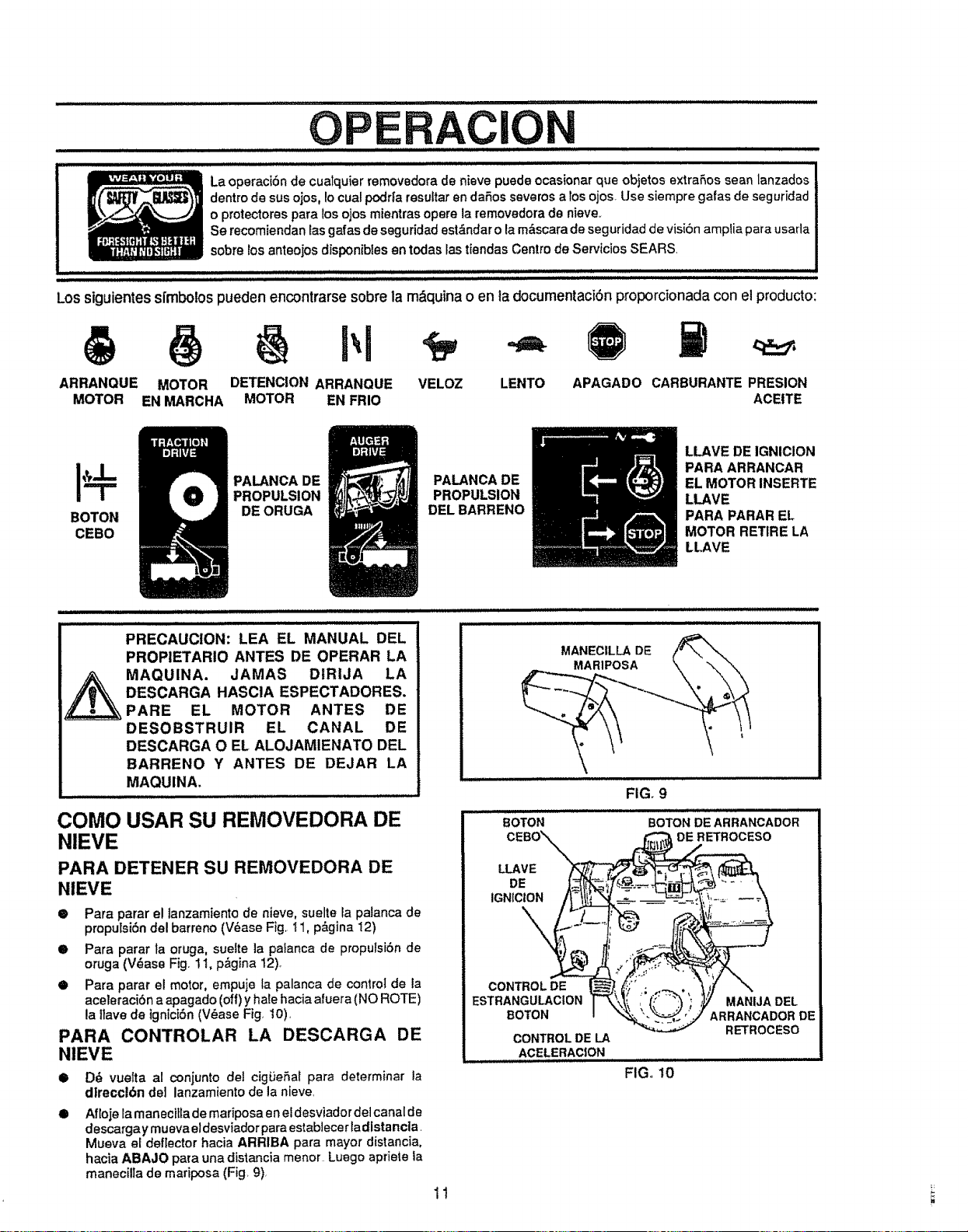
............................. _1 _ i iii i,iiiiiin1111ii
........................... ii i i i i iii ,1,1,11,1,1 ii i i
La operaciSn de cuatquier removedora de nieve puede ocasionar que objetos extraSos sean lanzados
dentro de sus oios, Io cual podr|a resuftar en daSos severos a los ojos. Use siempre galas de seguridad
o protectores para los ojos mientras opera la removedora de nieve,,
Se recomiendan las galas de seguridad est&ndar o la m&scara de seguridad de visiSn amplia para usada
sobre los anteojos disponibles en todas las tiendas Centro de Servicios SEARS.
Los siguientess{rnbolospueden encontrarse sobre la m&quinao en la documentaci6n proporcionada con el producto:
ARRANQUE MOTOR APAGADO CARBURANTE PRESION
MOTOR EN MARCHA ACEITE
DETENCION ARRANQUE VELOZ LENTO
MOTOR EN FRIO
I@
BOTON
CEBO
PALANCA DE
PROPULSION
DE ORUGA
PALANCA DE
PROPULSION
DEL BARRENO
LLAVE DE IGNICION
PARA ARRANCAR
EL MOTOR INSERTE
LLAVE
PARA PARAR EL
MOTOR RETIRE LA
LLAVE
PRECAUCION: LEA EL MANUAL DEL
PROPIETARIO ANTES DE OPERAR LA
MAQUINA. JAMAS DtRIJA LA
DESCARGA HASClA ESPECTADORESo
PARE EL MOTOR ANTES DE
DESOBSTRUIR EL CANAL DE
DESCARGA O EL ALOJAMIENATO DEL
BARRENO Y ANTES DE DEJAR LA
MAQUINA,
COMO USAR SU REMOVEDORA DE
NIEVE
PARA DETENER SU REMOVEDORA DE
NIEVE
• Para parar el tanzamiento de nieve, suelte la palanca de
proputsiSn del barreno (V_ase Fig. _1, p&gina 12)
• Para parar la oruga, suelte la paianca de propuisi6n de
oruga (V_ase Fig. 1t, p&gina 12).
• Para parar el motor, empuje la palanca de control de la
aceleraci6n a apagado (off)y hale hacia aluera (NO ROTE)
la llave de ignici6n (V_ase Fig, 10),
CONTROLAR LA DESCARGA DE
PARA
NIEVE
o
o
D_ vuelta al conjunto del cigi_eSal para determinar la
dlrecct6n de] lanzamiento de la nieve,
Afloje la manecitla de mariposa en el desviadordel canal de
descargay mueva eldesviadorparaestablecerladistancla,
Mueva el deflector hacia ARRIBA para mayor distancia,
hacia ABAJO para una distancia menor Luego apriete la
manecilla de mariposa (Fig 9),
1!
MANEC|LLADE ti_-_
FIG. 9
BOTON
CEBO\'\\
U.AVE
CONTROLDE
ESTRANGULACtON
BOTON
CONTROLDE LA
ACELERACION
iiii ii1,
FIG,, 10
BOTON DE ARRANCADOR
DE RETROCESO
MANIJA DEL
ARRANCADOR DE
RETROCESO
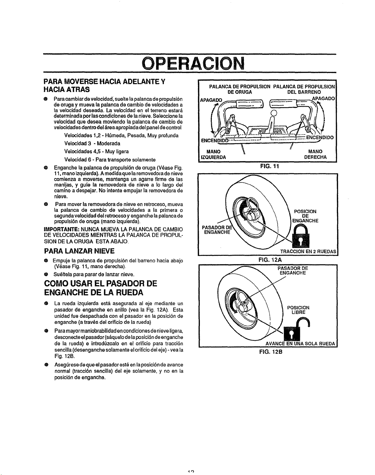
PARA IVIOVERSE HACIA ADELANTE Y
HACIA ATRAS
®
@
Para cambiar de velocidad, sueite la palanca de propulsi6n
de oruga y mueva la palanca de cambio de velocidades a
la velocidad deseada. La velocidad en el terreno estar,_
determinada por las condicionesde la nieve. Seleccione la
velocidad qua desea moviendo ta palanca de cambio de
velocidades dentro del drea apropiada del panel de control
Ve!ocidades 1,2 - H_3meda, Pesada, Muy profunda
Velocidad 3 - Moderada
Velocidades 4,5 - MW ligera
Velocidad 6 - Para transporte solamente
Enganche la pa]anca de propulsi6n de oruga (V_ase Fig_
11, mano izquierda). A medidaque la removedota de nieve
comienza a moverse, mantenga un agarre firme de las
manijas, y gu[e la removedora de nieve a Io largo del
camino a despejaro No intents empujar la removedora de
niave.
O Para mover la removedora de nieve en retroceso, mueva
la palanca de cambio de velocidades a la primera o
segunda velocldad del retrocesoy enganche la palanca de
propulsi6n de oruga (mano izquierda).
IMPORTANTE: NUNCA MUEVA LA PALANCA DE CAMBIO
DE VELOClDADES MIENTRAS LA PALANCA DE PROPUL-
SION DE LA ORUGA ESTA ABAJO.
PARA LANZAR NIEVE
Q Empuie la palanca de proputsi6ndet barrene hacia abajo
(V_ase Fig.. 11, mano derecha)..
® Sudltela pata parar de ianzar nieve.
COMO USAR EL PASADOR DE
ENGANCHE DE LA RUEDA
@ La rueda izquierda est& asegurada at eje mediante un
pasador de enganche en aniilo (vea la Fig. 12A).. Esta
unidad fue despachada con el pasador en ta posici6nde
enganche (a tray,s del orificiode la rueda)
® Para mayor maniobrabilidad en condiciones de nieve ligera,
desconecteelpasador (sdquelo de la posici6n de enganche
de la rueda) e intmd(lzcalo en ef orificio para tracci6n
sencitia (desenganche sotamente el orificiodet eje) - yea la
Fig,,12B,
®
Asegetese de qua el pasadorestden laposicidnde avance
normal (tracci6n sencilla) de_ eje solamente, y no en ta
posici6n de enganche.
PALANCA DE PROPULSION PALANCA DE PROPULSION
DE ORUGA DEL BARRENO
IZQUIERDA
FIG, 11
MANO
DERECHA
i HH
ENGANCHE
POSICION
DE
ENGANCHE
i
i
i
ii
TRACCIONEN 2 RUEDAS
IG. ................................
.... ,-,,o,,_,,,_"'_';'OR'"_....................
ENGANCHE
POSIC|ON
LIBRE
AVANCE EN UNASOLA RUEDA
FIG, 12B
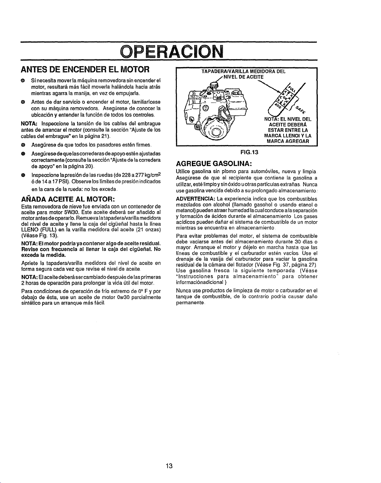
, illl i
OPERAC|O
ANTES DE ENCENDER EL MOTOR
e Si necesita mover la m_,quina removedora sin encender el
motor, resultar& m_s f&cil moverta ha!_ndola hacia atr_s
mientras agarra la manija, en vez de empujarla,
O Antes de dar servicio o encender el motor, tamiliar[cese
con su m_quina removedora., Aseg0rese de conocer la
ubicaci6n y entender la funci6n de todos los controles,
NOTA: Inspeccione la tensiSn de los cables del embrague
antes de arrancar el motor (consulte la seccibn "Ajuste de los
cables del embrague" en la p&gina 21)_
@ Aseg0rese de que todos los pasadores est_n firmes,
® AsegSrese deque lascorrederas de apoyo est_n ajustadas
correctamente {consulte la secci6n "Ajuste de lacorredera
de apoyo"en la p,Sgina20).
@ Inspeccione la presi6n de las ruedas (de 228 a 277 kg/cm2
6 de t4 a 17 PSt),, Observe los llmites de presi6n indicados
en ta cara de la rueda: no los exceda.
AI_ADA ACEITE AL MOTOR:
Esta removedora de nieve fue enviada con un contenedor de
aceite pare motor 5W30. Este aceite deber& ser afadido al
motor antes de operarloo Remueva latapaderaJvarilla medidora
det nivel de aceite y Ilene la caja del cig_efal haste la linea
LLENO (FULL) en la varilla medidora del aceite (21 onzas)
(V_ase Fig, 13)..
NOTA: El motor podrla ya contener algo de acelte reslduaL
Revise con frecuencla al Ilenar la caJa det ctgSef_al. No
exceda la medlda.
Apriete la tapadera/varitla medidora del nivei de aceite en
forma segura cada vez que revise el nivel de aceite
NOTA: E1aceite deber& sercambiado despu_s de las primeras
2 horas de operaci6n pare prolongar la vide 0til del motor_
Para condiciones de operacidn de fdo extremo de 0° F y por
debajo de _sta, use un aceite de motor 0w30 parcialmente
sint_tico pare un arranque m&s f&cil.
TAPAbERAPCARiLLA MEDIDOR; _, DEL ...............
NIVEL DE ACEITE
EL:
ACEITE DEBERA
ESTARENTRE LA
MARCA LLENOIY LA
MARCAAGREGAR
FIG,t3
AGREGUE GASOLINA:
Utitice gasolina sin plomo para autom6vites, nueva y limpia
Asegt_rese de que et recipiente que contiene la gasolina a
utilizer, est_ limpioy sin 6xido u otras particulas extraSas. Nunca
use gasoline vencida debido a su prolongado almacenamiento ,
ADVERTENCIA: La experiencia indica que los combustibles
mezclados con alcohol (ltamado gasohot o usando etanol o
metanol) puedenatraer humedad lacualconduce ala separaci6n
y formaci6n de &cidos durante et almacenamiento Los gases
acidicos pueden daSar el sistema de combustible de un motor
mientras se encuentra en almacenamiento
Pare evitar problemas del motor, el sistema de combustible
debe vaciarse antes del almacenamiento durante 30 dias o
mayor Arranque el motor y d_jelo en marcha haste que las
l_neas de combustible y ef carburador est_.n vac{os Use el
drenaje de ta vasija del carburador pare racier la gasoline
residual de la c&mara del flotador (V_ase Fig 37, p&gina 27)
Use gasolina fresca la siguiente temporada (V_ase
"lnstrucciones pare almacenamiento" para obtener
informacibnadicional)
Nunca use productosde iimpieza de motor o carburador en el
tanque de combustible, de Io contrario podria causer da_,o
permanente_
13
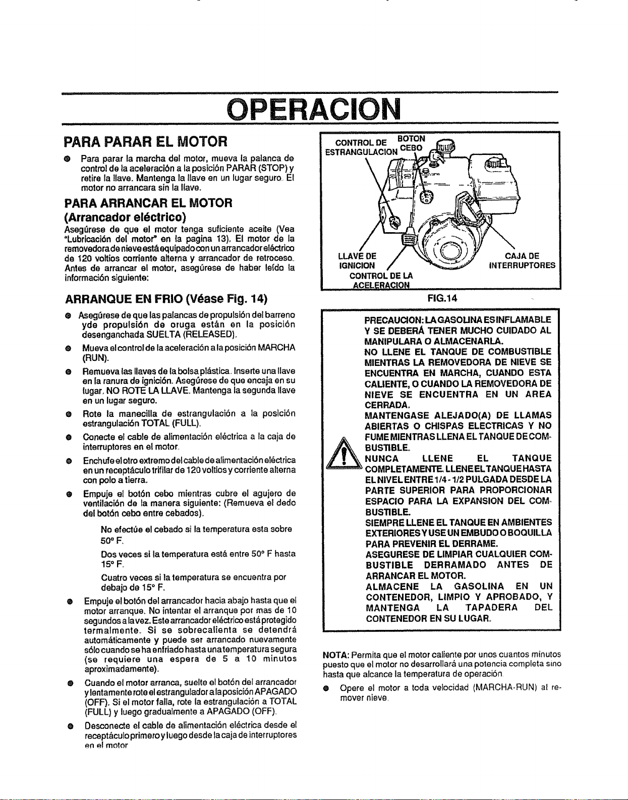
OPERACION
PARA PARAR EL MOTOR
®
Pare parar la maroha del motor, mueva la paianca de
control de la aceleraci6n a la posici6n PARAR (STOP) y
retire la llave. Mantenga la Have en un lugar segum El
motor no arrancara sin la Ilaveo
PARA ARRANCAR EL MOTOR
(Arrancador eldctrico)
AsegQrese de que el motor tenga suficiente acoite (Yea
"Lubricacidn del motor" en ta pagina 13),. El motor de ia
removedoradenieve est_zequipadocon un arrancador elc_ctrico
de 120 vottios cordente alterna y arrancador de retrocoso.
Antes de arrancar el motor, aseg_rese de haber le{do {a
informaci6n siguiente:
ARRANQUE EN FRIO (V_ase Fig. 14)
e Aseg_rese de que las palancas de propulstSndel barreno
yde propulsidn de oruga estlzn an la posici6n
desenganchada SUELTA (RELEASED).
e Mueva el control de la aceleraci6n ala posici6n MARCHA
(RUN).
e Remueva {as Ilaves de {a boise pl_stica, inserte una Uave
an la ranura de ignici6n°Aseg_rese de que encaja an su
lugar, NO ROTE LA LLAVE. Mantenga la segunda llave
an un lugar seguroo
• Rote ta maneci!la de estrangulaci6n ala poslci6n
estrangulaci6n TOTAL (FULL)°
® Conecte el cable de alimentaci6n el6ctrica a la caja de
interruptoresen el motor.,
e Enchufeelotroextremodelcabte deatimentaci6n e!6ctrica
en un recept_cutotrifitarde 120 voltiosy corrientealterna
con polo a tierrao
• Empuje et bot6n cebo mientras cubre el agujero de
ventilaciSn de la manera siguiente: (Remueva el dedo
del bot6n cebo entre cebados),,
No efect_e el cebado sila temperatura esta sobre
50 ° F_
Dos vecos sila temperatura est& entre 50° F hasta
15° F.
Cuatro vecos si la temperatura se encuentra pot
debajo de 15° Fo
e Empuje el bot6n del arrancador hacia abajo hasta que el
motor arranque. No intentar el arranque pot mas de 10
segundos a lavez, Este arrancadot eI_ctricoestd protegido
termalmenteo Si se sobrecalienta se detendr_
autom&ticamente y puede set arrancado nuevamente
s61ocuandose ha enfriado haste unatemperatuta segura
(se requiem una espera de 5 a 10 minutos
aproximadamente).
• Cuando el motor arranca, suelte el bot6n del arrancadot
y lentamente roteel estranguladorala posiciSnAPAGADO
(OFF),, Si el motor falla, rote la estrangulaci6n a TOTAL
(FULL) y luego gradua_mente a APAGADO (OFF),.
• Desconecte el cable de alimentaci6n ei_ctdca desde el
receptbculo primeroy l uego desde ta caja de interruptores
en e! motor
\
LLAVEDE
IGNICION
CONTROLDE LA
ACELERACION........
CAJA DE
INTERRUPTORES
FIG.14
PRECAUClON: LA GASOLINA ESINFLAMABLE
Y SE DEBERA TENER MUCHO CUIDADO AL
MANIPULARA O ALMACENARLA.
NO LLENE EL TANQUE DE COMBUSTIBLE
MIENTRAS LA REMOVEDORA DE NIEVE SE
ENCUENTRA EN I=_ARCHA, CUANDO ESTA
CALIENTE, O CUANDO LA REMOVEDORA DE
NIEVE SE ENCUENTRA EN UN AREA
CERRADA,
MANTENGASE ALEJADO(A) DE LLAMAS
ABIERTAS O CHISPAS ELECTRICAS Y NO
FUME MIENTRAS LLENA EL TANQUE DECOM-
BUSTIBLEo
NUNCA LLENE EL TANQUE
COMPLErAMENTE. LLENE ELTANQUE HASTA
ELNIVEL ENTRE 1/4 - 1/2 PULGADA DESDE LA
PARTE SUPERIOR PARA PROPORCIONAR
ESPACIO PARA LA EXPANSION DEL COM-
BUSTIBLE.
SIEMPRE LLENE EL TANQUE EN AMBIENTES
EXTERIORESY USE UN IEMBUDO O BOQUILLA
PARA PREVENIR EL DERRAME,
ASEGURESE DE MMPIAR CUALQUIER COM-
BUSTIBLE DERRAMADO ANTES DE
ARRANCAR EL MOTOR.
ALMACENE LA GASOLINA EN UN
CONTENEDOR, LIMPIO Y APROBADO, Y
MANTENGA LA TAPADERA DEL
CONTENEDOR EN SU LUGAR,.
NOTA: Permita que el motor caliente por unos cuantos minutos
puesto que el motor no desarroliara una potencia completa sino
haste que atcance la temperatura de operaciSn
® Opere el motor a toda veiocidad (MARCHA-RUN) at re-
mover nieve,
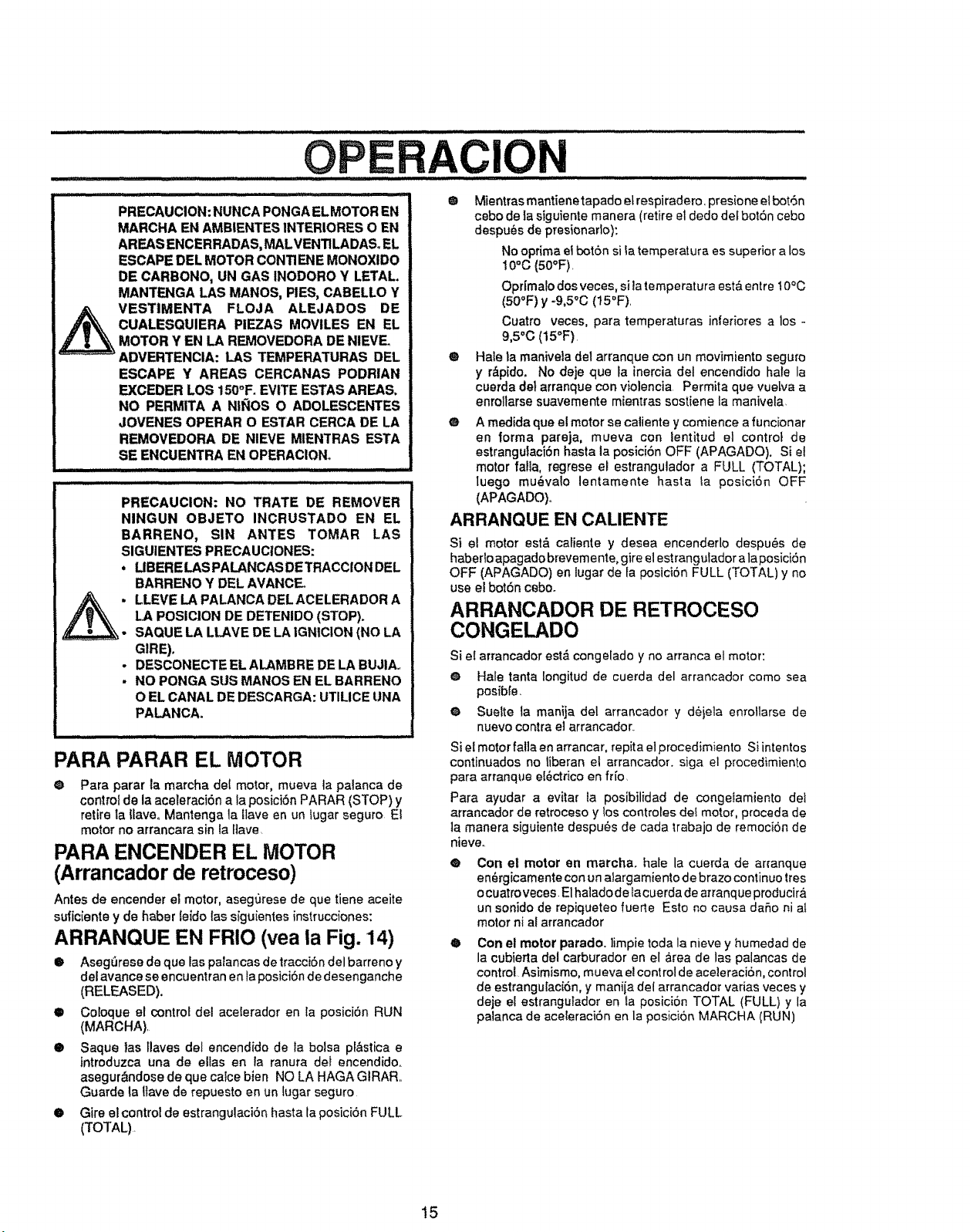
PRECAUCION: NUNCA PONGA EL MOTOR EN
MARCHA Eli AMBIENTES INTERIORES O EN
AREAS ENCERRADAS, MALVENTILADAS_ EL
ESCAPE DEL MOTOR CONTIENE MONOXIDO
DE CARBONO, UN GAS INODORO Y LETAL
MANTENGA LAS MANOS, PIES, CABELLO Y
VESTIMENTA FLOJA ALEJADOS DE
CUALESQUIERA PIEZAS MOVILES EN EL
MOTOR Y EN LA REMOVEDORA DE NIEVE
ADVERTENCIA: LAS TEMPERATURAS DEL
ESCAPE ¥ AREAS CERCANAS PODRIAN
EXCEDER LOS 150°F. EVtTE ESTAS AREAS.
NO PERMITA A NiI_OS O ADOLESCENTES
JOVENES OPERAR O ESTAR CERCA DE LA
REMOVEDORA DE NIEVE MIENTRAS ESTA
SE ENCUENTRA EN OPERAClONo
PRECAUCION: NO TRATE DE REMOVER
NINGUN OBJETO INCRUSTADO EN EL
BARRENO, SIN ANTES TOMAR LAS
SIGUIENTES PRECAUC1ONES:
, LIBERE LAS PALANCAS DETRACCION DEL
BARRENO ¥ DEL AVANCE_
_: LLEVE LA PALANCA DEL ACELERADOR A
LA POSICION DE DETENIDO (STOP).
SAOUE LA LLAVE DE LA IGNICtON (NO LA
GIBE).
- DESCONECTE EL ALAMBBE DE LA BUJIA.,
. NO PONGA SUS MANOS EN EL BARRENO
O EL CANAL DE DESCARGA: UTILICE tJNA
PALANCA.
PARA PARAR EL MOTOR
@ Para parer la marcha del motor, mueva ta palanca de
control de la aceleraci0n a la posici6n PARAR (STOP) y
retire la llave. Mantenga la flave en un lugar seguro El
motor no arrancara sin la fiave
PARA ENCENDER EL MOTOR
(Arrancador de retroceso)
Antes de encender el motor, asegurese de que tiene aceite
suficiente y de haber leido las siguientes instrucciones:
ARRANQUE EN FRIO (vea la Fig. 14)
• Asegr_rese de que las palancas detracci6n del barreno y
del avance se encuentran en la posici6n de desenganche
(RELEASED).
• Coloque el control del acelerador en la posici0n RUN
(MARCHA)
Q Saque tas flares del encendido de la bolsa pl&stica e
introduzca una de elias en fa ranura det encendido.
asegur&ndose de que calce bien NO LA HAGA GIRAR
Guarde la Ilave de repuesto en un lugar seguro
• Gire el control de estrangulaci0n hasta la posici6n FULL
(TOTAL)
® Mientrasmantienetapadoetrespiradero.presioneelbot,Sn
cebo de Ia siguiente manera (retire el dedo det bot6n cebo
despu_s de presionaflo):
No optima el bot6n sila temperatura es superior a los
10°c (5o°F)
Oprimalo dos veces, sila temperatura est& entre 10°C
(50°F) y -9,5°C (15°F)
Cuatro veces, pare temperatures inferiores a los -
9,5"0 (15°F)
@ Hale la manivela de1arranque con un movimiento seguro
y r&pido. No deje que la inercia del encendido hale la
cuerda deI arranque con violencia Permita que vuelva a
enrollarse suavemente mientras sostiene la manivela,
@ A medida que el motor se caliente y comience a funcionar
en forma pareja, mueva con lentitud el control de
estrangutaci6n hasta la posici6n OFF (APAGADO). Si el
motor falta, regrese el estrangulador a FULL (TOTAL);
Iuego mu_valo lentamente haste ta posiciOn OFF
(APAGADO)o
ARRANQUE EN CALIENTE
Si el motor est& caliente y desea encenderlo despu6s de
haberlo apagado brevemente, gire el estrangutador ala posici6n
OFF (APAGADO) en lugar de la posici6n FULL (TOTAL) y no
use e! bot6n cebo.
ARRANCADOR DE RETROCESO
CONGELADO
Si e! arrancador est& congelado y no arranca el motor:
@ Hale tanta Iongitud de cuerda del arrancador como sea
posible,
@ Suette la manija del arrancador y deiela enrollarse de
nuevo contra el arrancador.
Si el motor falla en arrancar, repita el procedimiento Si intentos
continuados no liberan el arrancador, siga el procedimiento
pare arranque et_ctrico en frfo
Para ayudar a evitar la posibilidad de congelamiento det
arrancador de retroceso y los controles clef motor, proceda de
]a manera siguiente despu6s de cada trabajo de remoci6n de
nieveo
@
Con el motor en marcha, hale la cuerda de arranque
en_rgicamentecon un aiargamiento de brazo continue tres
ocuatro veces. E1halado de lacuerda de arranque producir&
un sonido de repiqueteo fuerte Esto no causa daSo ni al
motor ni al arrancador
®
Con el motor parado. ]impie toda la nieve y humedad de
la cubierta del carburador en el _rea de las palancas de
control Asimismo, mueva el control de aceleraci6n, conlrol
de estrangulaci6n, y maniia del arrancador vadas veces y
deje el estrangufador en la posici6n TOTAL (FULL) y la
palanca de aceleraci6n en la posici6n MARCHA (RUN)
15
.... Illll II I II
OPERACION
PISTAS SOBRE LANZAiVUENTO DE ® En superficies de grava o roca triturada, posicione las
NIEVE correderas de apoyo a 1-1/4 puigadas pot debajo de la
barra raspadora (V_ase el p&rrafo "C6mo ajustar la altura
®
Para mayor eficienc[a de lanzamiento de nieve durante la
remoci6n de la misma, ajuste ia vetocidad en el terreno,
NUNCA la aceleraci6n. Avance fentamente en nieve
profunda, congelada, o h_meda.. Si la oruga desliza,
reduzcalavelocidad hacia ad elante. El motor esta diseSado
para brindar un rendimiento m_imo bajo aceleraclSn total
y debe ser operado eneste valor de potencia en rode
momento_
@ E! lanzamientode nieve es m&s eficiente si ta remoci6n de
ta misma se efectSa inmediatamente despu6s de su caldao
O Para una remoci6n completa de la nieve, trasiape
ligeramente cada camino adoptado previamente.
O La nieve deberfa serdescargada en la direcciSn de1viento
siempre que sea posible..
e Para uso normal, posicione las corredetas de apoyo de
manera tal que la barra raspadora se encuentte 1/8 de
pulgada sobre las correderas de apoyo., Para superficies
de nieve dura extremadamente compacta, ajuste las
correderas de apoyo hacia arriba de manera que la barra
raspadora haga contacto con el terreno.
de las correderas de apoyo" en la p&gina 20) Las rocas y
grava no deber&n set recogidas y ianzadas por la rn,_quina
O Si fa part@delantera de la removedora de nieve tiene la
tendencia de elevarse reduzca lavelocidad sobre ei terreno
y enganche el sistema de transfetencia de peso
® Despu_s de que se haya completado el ]anzamiento de
n[eve, permita que el motor se encuentre en reposo por
unos cuantos minutos, Io cual derretir& la nieve y hielo
acumulado del motor.,
®
@
Efect0e una limpieza completa de la removedora de nieve
luego de cada usa.
Remueva la acumu]aciSn de hielo y nieve y todo material
extraf_o heterog_neo de la removedota de nieve en su
total[dad, y lave con agua (si rues@posib_e) para remover
todasaluotrassubstanciasquimicas Sequela removedora
de nieve_
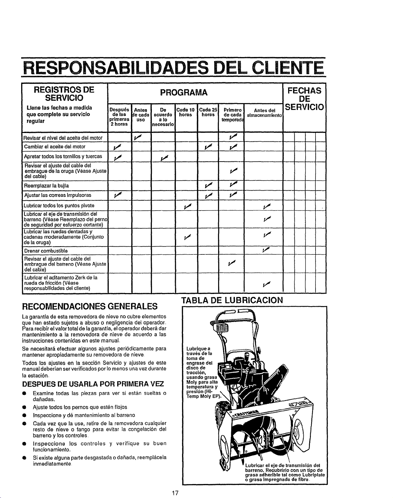
L CLI T
III I JJlllllllllll III III I IIIIIIIIIIIIIIIIIII II I i iiiii i_l_ll_lllll_lllllllllllil ........ ........ ii iiiiiiiiiiiiiiii i i
REGISTROS DE PROGRAMA
SERVICIO
.... /IIHIIJlIIII[II I II IIIIII III
Llene las fechas a modlda Despu6s Antes De Cede10 Cada 25
que complete su servIc[o de las :lecads acuerdo hems horas
regular pr|meras uso s to
2 bores _ecesarlo
Prlmero Antes de!
de cads a[macenamtento
temporadi
FECHAS
DE
SERVICIO
Reviser ef nlveldel acelte del motor
Cambi_etaceitedeimoto,
Apretar todoslostornt[iosy tuercas pJ
Fl_visarel ajustede}cabledel
embrague de la oruga(V_ase Ajuste
del cable)
Reemplazar la buJla
Ajustar tas correaslmpulsoras
Lubdcartodoslos puntos plvote
Lubric_ el eje de transrnisi6n dei _ .....
ibarreno (V_ase Reemptazo del perno
de seguridadpor esfuerzocortante)
LUS_c_ iasrueclasdentadas y ......
cadenas moderadamente (Conjunto
de la oruga)
Drenar combustible
R_vis"re!aius_e_i cA'_iedei ' ...........' '
embraguedel barreno (V_ase Ajuste
del cable)
Lubdcar el aditamento Zerk de la
ruedade fricci6n (V6ase
responsabtltdadesdel cltente) ......... l..
RECOMENDAClONES GENERALES
II'
v"
i
v"
v"
TABLA DE LUBRICACION
,,, _ll ,,H ii ,i, I,H
La garantla de esta removedora de nieve no cubre elementos
que han estado sujetos a abuso o negligencia def operador_
Para recibTrel valor totalde la garantla, el operador deber&dar
mantenimiento ata removedora de nieve de acuerdo alas
instrucciones contenidas en este manual
Se necesitar& efectuar algunos ajustes peribdicamente pare
mantener apropiadamente su removedora de nieve,
Todos los ajustes en la secciSn Servicio y ajustes de este
manual deber{an set verificados por 1omenos una vez durante
ta estaciSn,,
DESPUES DE USARLA POR PRIMERA VEZ
• Examine todas las piezas pare ver si est;_n sueltas o
daSadas.
• Ajuste todos los pernos que estL,n f{ojos
• Inspeccione y d_ manten{miento a[ barreno
• Cada vez que la use, retire de la removedora cualquier
resto de nieve o fango pare evitar la congetaciSn del
barreno y los controtes,
• inspeccione los controtes y verffique su buen
funcionamientoo
6 Si existe alguna parte desgastada o daSada, reempf&cela
inmediatamente.
Lubrique a
trav_s de la
tome de
engrase del
d|sco de
traccl6n,
usando grass
Moly para alta
Lubrlcarel eje de transmlsl6ndel
barreno, Recubrirlo con un tipo de
grassadherlbtetsl como Lubrlplate
o grass tmpregnadade fibre,
17
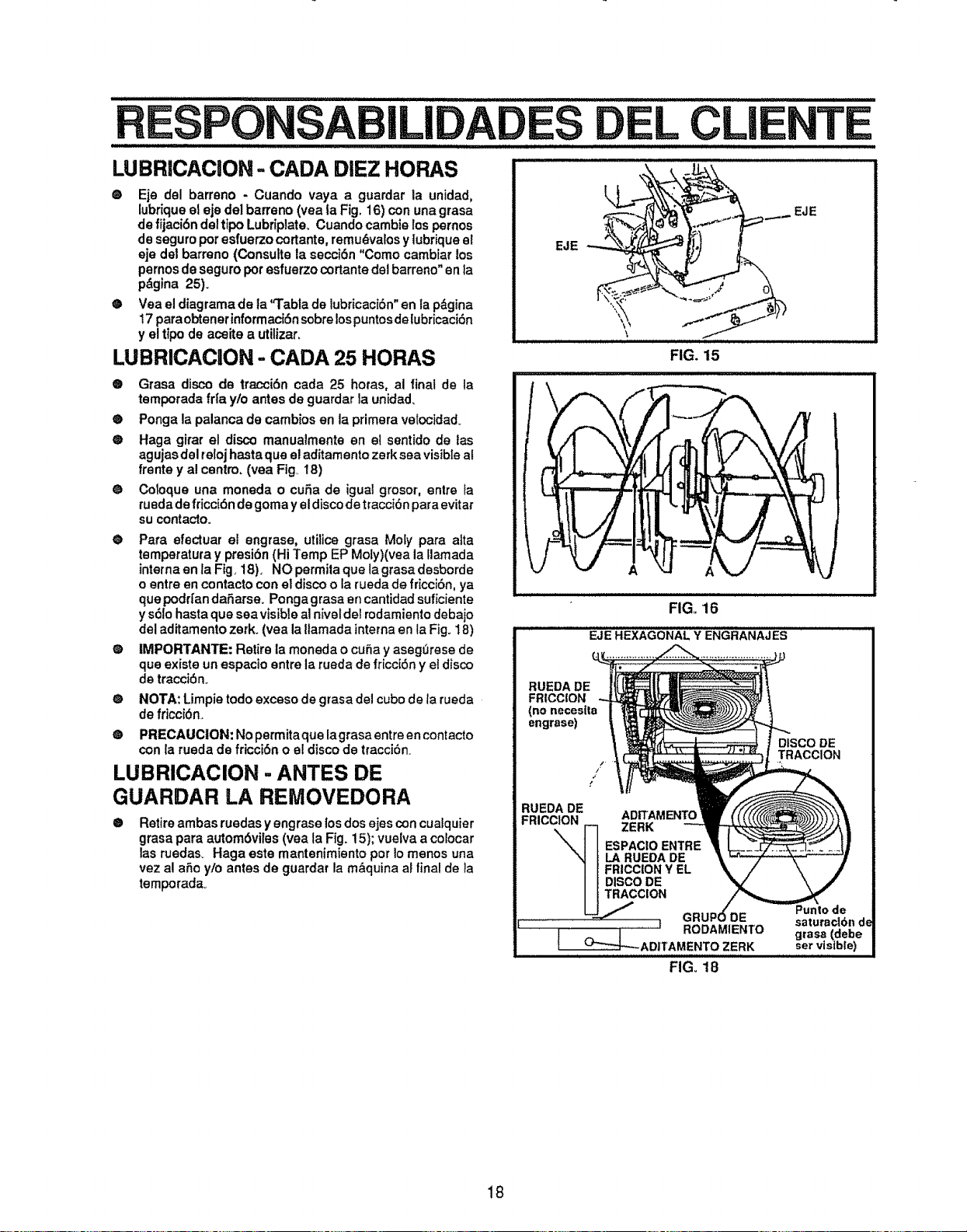
ES EL CLIENTE
LUBRJCACION =CADA DIEZ HORAS
® Eje del barreno - Cuando vaya a guardar la unidad,
lubriqueel eje del barreno (yea la Fig, 16) con una grasa
de fijaci6n del tipo Lubrip]ate_ Cuando cambie los pernos
de seguro pot esfuerzo cortante, remu_valos y lubriqueel
eje del barreno (Consult® la secci6n "Como cambiar los
pernos de seguro pot esfuerzo cortante del barreno" en la
p&gina 25).
e Vea el diagrama de la"Tabla de lubricaci6n" en la p,_gina
17 paraobtener informac_Snsobre lospuntosde lubricaci6n
y el ttpode acoite a utilizar,
LUBRICACION - CADA 25 HORAS
® Grasa disco de traocibn cada 25 hotas, al finat de la
temporada fr[a yto antes de guardar la unidad,
® Ponga la palanca de cambios en la primera vetocidad.
® Haga girar el disco manuaimente en el sentido de las
agujas del tetoj hastaque el aditamento zerk sea visible af
frente y al centro, (vea Fig. 18)
® Coloque una moneda o cuSa de igua] grosor, entre }a
rueda de fricci6n de goma y el disco de tracci6n para evitar
su contacto.
e Para efectuar el engrase, utilice grasa Mo[y para aita
temperatura y presi6n (Hi Temp EP Moly)(vea la [larnada
intema en la Fig. 18), NO permita que la grasa desborde
o entre en contacto con el disco o la rueda de friccibn, ya
que podri'an daSarse. Ponga grasa en cantidad suficiente
y s_lo hasta que sea visible a] n[vel del rodamiento debajo
del aditamento zerk. (vea la ltamada interna en la Fig. 18)
@ IMPORTANTE: Retire la moneda o cu5a y aseg_rese de
que exist® un espacio entre la rueda de fricc[bn y el disco
de tracci6n..
@
®
NOTA: Limpie todo exceso de grasa de] cubo de la rueda
de fricoi6n_
PRECAUCtON: No permita que lagrasa entre en contacto
con la rueda de fricciSn o el disco de tracciSn.
LUBRICACION - ANTES DE
GUARDAR LA REMOVEDORA
®
Retire ambas ruedas y engrase los dos ejes con cuatquier
grasa para autom6viles (vea la Fig. 15); vuelva a colocar
las ruedas_ Haga este mantenimiento por Io menos una
vez al a5o ylo antes de guardat la m&quina al final de la
temporada_
FIG. 15
FIG, 16
EJE HEXAGONAL Y ENGRANAJES
RUEDA DE
FRtCCION
(no necesll_a
engrase)
DISCO DE
TRACCION
RUEDA DE ADITAMENTO
FRICCION ZERK
ESPACIOENTRE
LA RUEDADE
FRICCIONY EL
DISCODE
TRACCION
............. _J
FIG. 18
Punlo (
satumc16n d_
grasa (debe
ser visible)
18
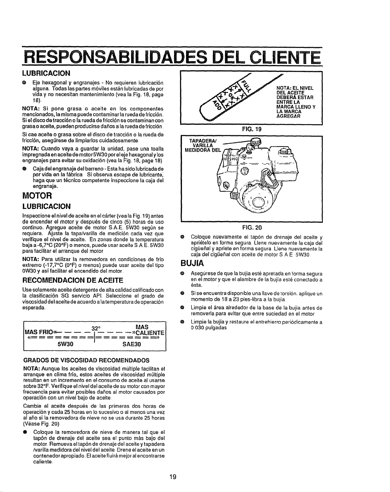
L CLi
LUBRICACION '
Q Eje hexagonal y engranajes - No requieren lubricaci6n
alguna, Todas las partes m6vites est&n lubricadasde pot
vida y no necesitan mantenimiento (yea la Fig,,18, page
!8)_
NOTA: Si pone grasa o aceite en los componentes
menclonados, la misma puede contaminarla rueda defricciOn,
Si et discode tracci6n o la ruedade fficci6n se contaminancon
grasao aceite, pueden pmducirsedaOosala rueda de fricci6n
Si cae aceite o grasa sobre el disco de traccidno la rueda de
fricci6n, aseg_i'ese de timpiados cuidadosamente,
NOTA: Cuando vaya a guardar la unidad, pase una toalla
impregnadaen aceitede motor5W30por eleje hexagonalylos
engranajes pare evitar su oxidacibn (yea la Fig, 18, page 18)
® Caja del engranaje del barreno- Esta ha sidoIubricadade
por vide en la f&brica Si observa escape de lubricante;
haga que un t6cnico competente inspeccione la caja del
engranaje.
MOTOR
LUBRICACION
Inspeccioneel nivel de aceite en el c_,rter (vea Ia Fig, 19) antes
de encender el motor y despu_s de cinco (5) horas de uso
continuo. Agregue aceite de motor SAE 5W30 seg0n se
requiera_ Aiuste la tapa/varilia de mediciOn cada vez que
verifique el niveI de aceite. En zonas donde fa temperature
baja a-6,7°C (20°F) o menos, puede user aceite SA E. 5W30
pare lacilitar el arranque del motor
NOTA: Para utilizer la removedora en condiciones de frfo
extremo (_17,7a0 (O°F) o menos) puede user aceite del tipo
0W30 y ast facilitar el encendido dei motor.
RECOMENDACION DE ACEITE
Use solamente aceite detergente de alta calidad caiificado con
Ea clasificacibn SG servicio API. Seleccione el grado de
viscosJdad del aceite de acuerdo a Ia temperature de operaciOn
esperada_
IMAS FRIOc*-- i 2° MAS
)>CALIENTE
5W30 SAE30
J;'ct',_ '__ ,_'._ DEL AC_ITE
A'tP..,, "',p,_T_P" DEBERA ESTAR
/ _.A_(=r/_,_/r ENTRELA
f "_'_'P.,_ MARCALLENO Y
a_ LA MARCA
AGREGAR
TAPADERA/
VARtLLA
MEDIDORADEL__
FIG,, 20
0 Coloque nuevamente el tap6n de drenaie del aceite y
apridtelo en forma segura Uene nuevamente la caja del
cig_ieOafy apriete en forma segura Liene nuevamente la
caja del cigLieOaf con aceite de motor S A E 5W30
BUJIA
o
Asegurese de que ]a bujia est_ apretada en iorma segura
en el motor y que el alambre de Ia bujia este conectado a
6sta_
® Si se encuentra disponible una 1lave de torsion, aplique un
momento de 18 a 23 pies-libra a la bujt'a
® Limpie ei &rea atrededor de ta base de la buiia antes de
removerla pare evitar que enlre suciedad en et motor
Q Limpie la bujia y restaure el entrehierro peri6dicamente a
0 030 pulgadas
GRADOS DE VISCOSIDAD RECOMENDADOS
NOTA: Aunque los aceites de viscosidad muttipie facilitan el
arranque en clime fr[o, estos aceites de viscosidad m0ItJple
resultanon un incremento en el consumo de aceite al usarse
sobre 32°F. Verifique el nivel del aceite de su motor con mayor
frecuoncia para evitar posibles daOos al motor causados por
oporaci6n con un nivef bajo de aceite
Cambie el aceite despu_s de las primeras dos horas de
operaci6n y cada 25 horas en to sucesivo o af menos una vez
at aRo sila removedora de nieve no se usa durante 25 horas
(V_ase Fig 20)
I! Coloque la removedora de nieve de manera ta_ que el
tapOn de drenaje deI aceite sea et punto m&s bajo del
motor. Remueva el tapbn de drenaje del aceite y tapadera
Narilla medidora del nivei del aceite Drene el aceite en un
contenedor apropiado. Elaceite fluir& mejot al encontrarse
cafiente
19
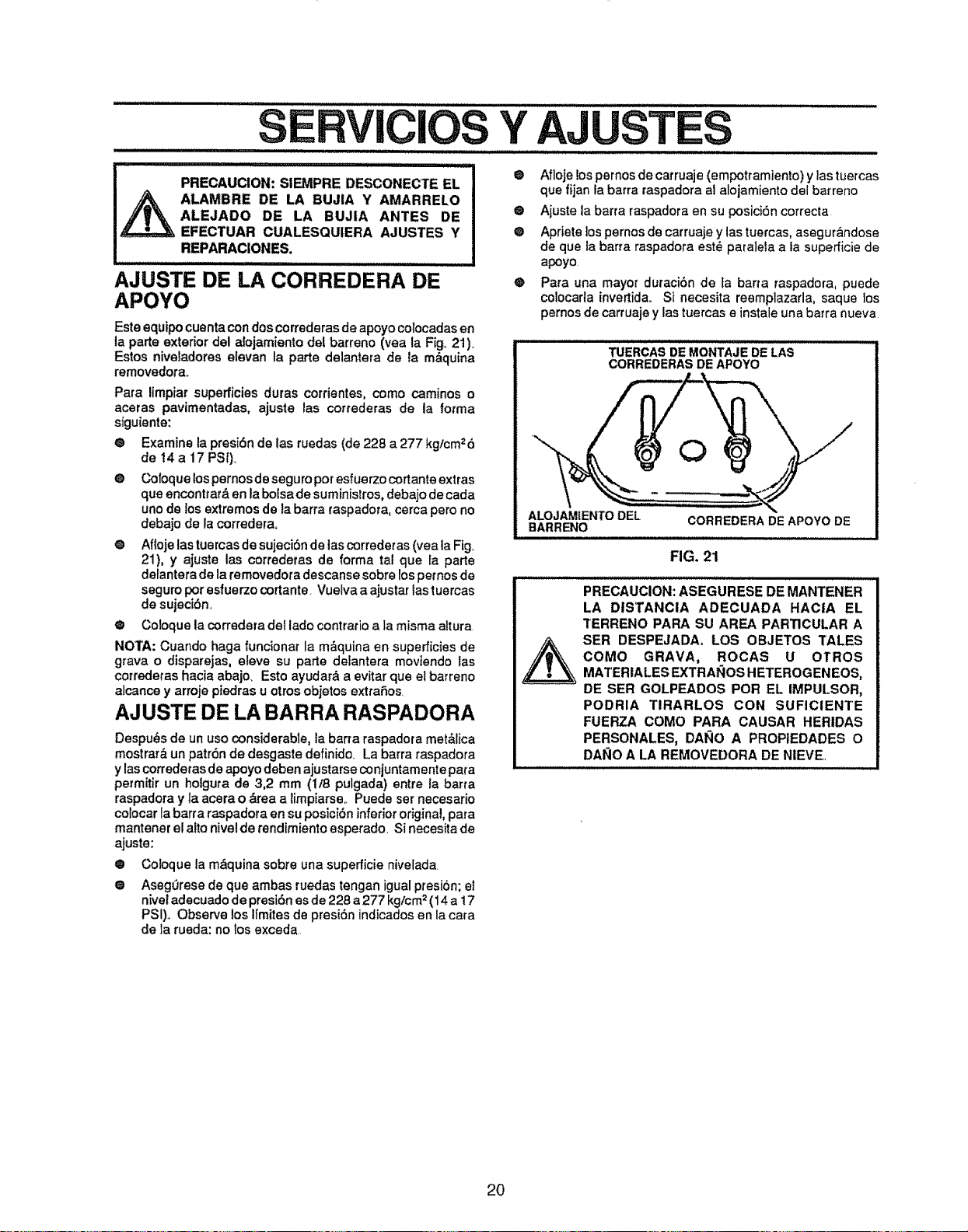
PRECAUCION: SIEMPRE DESCONECTE EL I
_ ALAMBRE DE LA BUJIA Y AMARRELO
I
ALEJADO DE LA BUJIA ANTES DE
EFECTUAR CUALESQUIERA AJUSTES Y
REPARACIONES.
lllIHIHIHll I ,,,',,,,,,,,,,,,,,
AJUSTE DE LA CORREDERA DE
APOYO
Este equipocuenta condos correderasde apoyo colocadas en
la parte exterior del afojamiento del barreno (vea la Figo21 ).
Estos niveJadores elevan la parte de]antera de la m&quina
removedorao
Pare limpiar superficies duras corrientes, como caminos o
aceras pavimentadas, ajuste las correderas de la forma
siguiente:
® Examine la presi6n de las ruedas (de 228 a 277 kg/cm26
de t4a 17 PSI).
O CoIoque los pernosde seguropor esfuerzocortanteextras
que enconttat& en la boisa de suministros, debajo de cada
uno de Ios extremos de la barra raspadora, cerca pero no
debajo de la correderao
o Afloje las tuercas de sujeci6nde las correderas (yea la Fig.
21), y ajuste las correderas de forma tel que ra parte
delantera de la removedora descanse sobre los pernosde
seguro por esfuerzo cortante. Vuelva a ajustar lastuercas
de sujedbn,
® Cotoque la corredera det lado contrario ala misma attura
NOIA: Cuando haga funcionar la m_quina en superficies de
grava o disparejas, eleve su parte delantera moviendo ias
correderas hacia abajo. Esto ayudar& a evitar que et barreno
alcance y arroje pledras u otros objetos extraSos
AJUSTE DE LA BARRA RASPADORA
Despu_s de un uso considerable, la barra raspadora met&lica
mostrar& un patr6n de desgaste definido_ La barra raspadora
y las correderas de apoyo deben ajustarse conjuntamente para
permitir un hoigura de 3,2 mm (1/8 putgada) entre la barra
raspadora y la acera o &tea a limpiarse,. Puede ser necesario
colocar ia barra raspadora en su posicibn inferiororigina!,para
mantener el afro nivel de rendimiento esperado, Si necesita de
ajuste:
• Coloque la m&quina sobre una superficie nivefada,
® Asegt_rese de que ambas ruedas tengan igual presi6n; el
nivet aclecuado de pres[6n es de 228 a277 kg/cm2(t4 a 17
PSI).. Observe los IImites de presi6n indicados en la cara
de ]a rueda: no los exceda
@ Afloje los pernosde carruaje (empotramiento) y las tuercas
que fijan la barra raspadora a] alojamiento del barreno
® Ajuste ta barra raspadora en su posiciSn correcta
® Apriete lospernos de carruaje y las tuercas, asegur&ndose
de que la barra raspadora est_ paralela aia superficie de
apoyo
@ Para una mayor duracibn de [a barra raspadora, puede
co]ocarla invertida. Si necesita reemplazarla, saque los
pernos de carruaje y Fastuercas e instale una barra nueva
TUERCAS DE MONTAJE DE LAS
CORREDERAS DE APOYO
ALOJAMIENTODEL CORREDERADE APOYO DE
BARRENO
FIG. 21
PRECAUCION: ASEGURESE DE MANTENER
LA DISTANCIA ADECUADA HAC|A EL
TERRENO PARA SU AREA PARTICULAR A
SER DESPEJADA. LOS OBJETOS TALES
COMO GRAVA, ROCAS U OTROS
MATERIALES EXTRA'lOS HETEROGENEOS,
DE SER GOLPF-ADOS POR EL IMPULSOR,
PODRIA TIRARLOS CON SUFICIENTE
FUERZA COMO PARA CAUSAR HERIDAS
PERSONALES, DANO A PROPIEDADES O
DAI_IOA LA REMOVEDORA DE NIEVE,.
2O
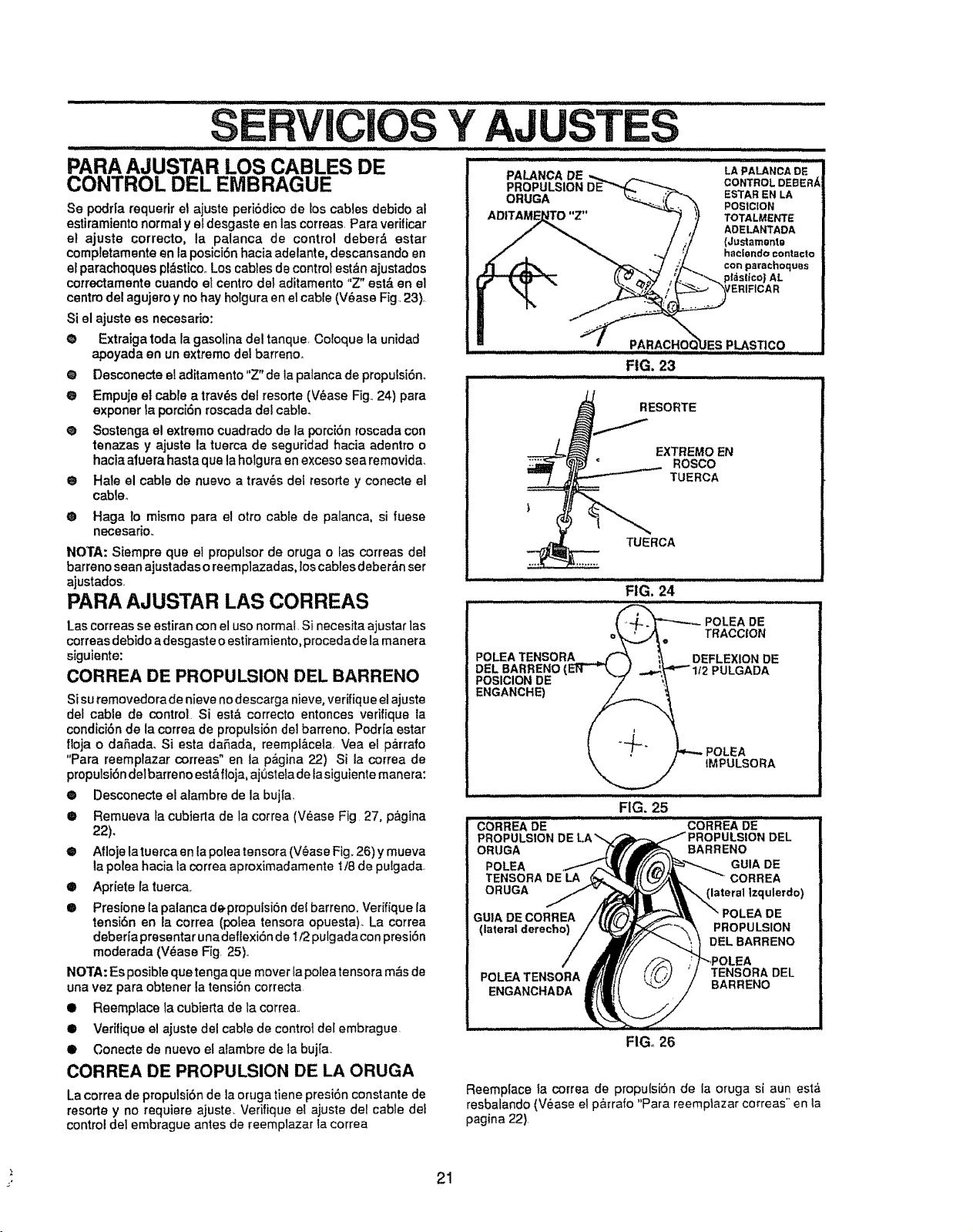
SERVlCiOS Y AJUSTES..............
i i iiiii1,111, i i, ii ii II,,I,H,,,, i . /,,,,, , i ii ,,,,,,,, i , ,,,,,, ...........
PARA AJUSTAR LOS CABLES DE
CONTROL DEL EMBRAGUE
Se podr|a requerir et ajuste peri6dico de los cables debido al
estiramiento normal yef desgaste an lascorreas. Pare verificar
el ajuste correcto, ta palanca de control deber_ ester
completamente en la posici6n hacia adelante, descansando an
erparachoques pl&sttco..Los cables de control est,_n ajustados
cotrectamente cuando el centre del aditamento "Z" est& en el
centre del agujero y no hay hoigura an el cable (V6ase Fig 23).
Si el ajuste es necesado:
• Extraiga toda la gasotina del tanque, Coloque la unidad
apoyada en un extreme del barreno.
@ Desconecte el aditamento "Z" de la palanca de propulsi6n..
® Empuje et cable a tray,s del rosette (V_ase Fig.. 24) pare
exponer la porci6n roscada del cable_
@ Sostenga e! extreme cuadrado de la porcibn roscada con
tenazas y ajuste la tuerca de seguridad hacia adentro o
hacia atuera basra que la holgura en exceso sea removida.
Q Hale el cable de nuevo a trav6s del rosette y conecte el
cableo
• Haga lo mismo para e! otto cable de palanca, si fuese
necesario.
NOTA: Siempre qua et propulsor de oruga o las correas del
barreno seen ajustadas o reemplazadas,los cables deber&n ser
ajustados
PARA AJUSTAR LAS CORREAS
Las correas se estiran con el use normal. Si necesita ajustar las
correas debido a desgaste o estiramiento, procedade lamanera
siguiente:
CORREA DE PROPULSION DEL BARRENO
Si su removedora de nieve no descarga nieve, verifique el ajuste
del cable de control Si est& correcto entonces verifique la
condiciSn de la correa de propulsiSn del barreno. Podr[a ester
floja o daSacla. Siesta daRada, reempt&cela, Vea el p_rrafo
"Pare reemplazar correas" en la p_gina 22) Si la correa de
propuisi6ndelbarreno est& floja, aj0stela de fasiguiente manera:
® Desconecte el alambre de la bujfa.
® Remueva la cubierla de la correa (V_ase Fig 27, pagina
_2).
• Atloje latuercaen la polea tensora (V6ase Fig. 26) y mueva
la polea hacia ta correa aproximadamente !/8 de puigada
• Apriete [a tuerca,
• Presione Ia palanca de.propufsiSn del barreno. Verifique [a
tensi6n en la correa (polea tensora opuesta)_ La correa
deberfa presentar una deflexi6n de 1/2 pulgadacon presi6n
moderada (V_ase Fig. 25)1.
NOTA: Es posibte que tonga que mover lapotea tensora m_s de
una vez pare obtener la tensiSn correcta
Q Reemplace la cubierta de la correa..
• Verifique el ajuste del cable de control del embrague
Q Conecte de nuevo el atambre de la bujta..
CORREA DE PROPULSION DE LA ORUGA
La correa de propulsiSn de la oruga tiene presi6n constante de
resorte y no requiere ajuste. Verifique el ajuste dei cable del
control del embrague antes de reemplazar la correa
PALANCADE
PROPULSION
ORUGA
RG': 23 ..............
i H i,, ...............................
LA PALANCA DE
CONTROL DEBER/_
ESTAR EN LA
POSIC|ON
TOTALMENTE
ADELANTADA
(Justam_nt_
haclendo contacto
con parachoqu_s
AL
/ERIFICAR
ES PLAST]CO
HI , ,H
RESORTE
EXTREMO EN
€ ROSCO
TUERCA
TUERCA
FiG. 24
_ POLEA DE
o_,,A_. TRACC'ON
POLEATENSORA__ i_ DEFLEXIONDE
DEL BARREN{)(EFr_ J ..4._'-'112 PULGADA
POSICIONDE "7 "_
ENGANCHE) _.__
! _ POLEA
\_..._ IMPULSORA
FIG. 25
FIG. 26
Reemplace la correa de propulsiSn de ia oruga si aun est,_
resbalando (V_ase el p_rafo "Para reemplazar correas" en Ia
pagina 22).
21
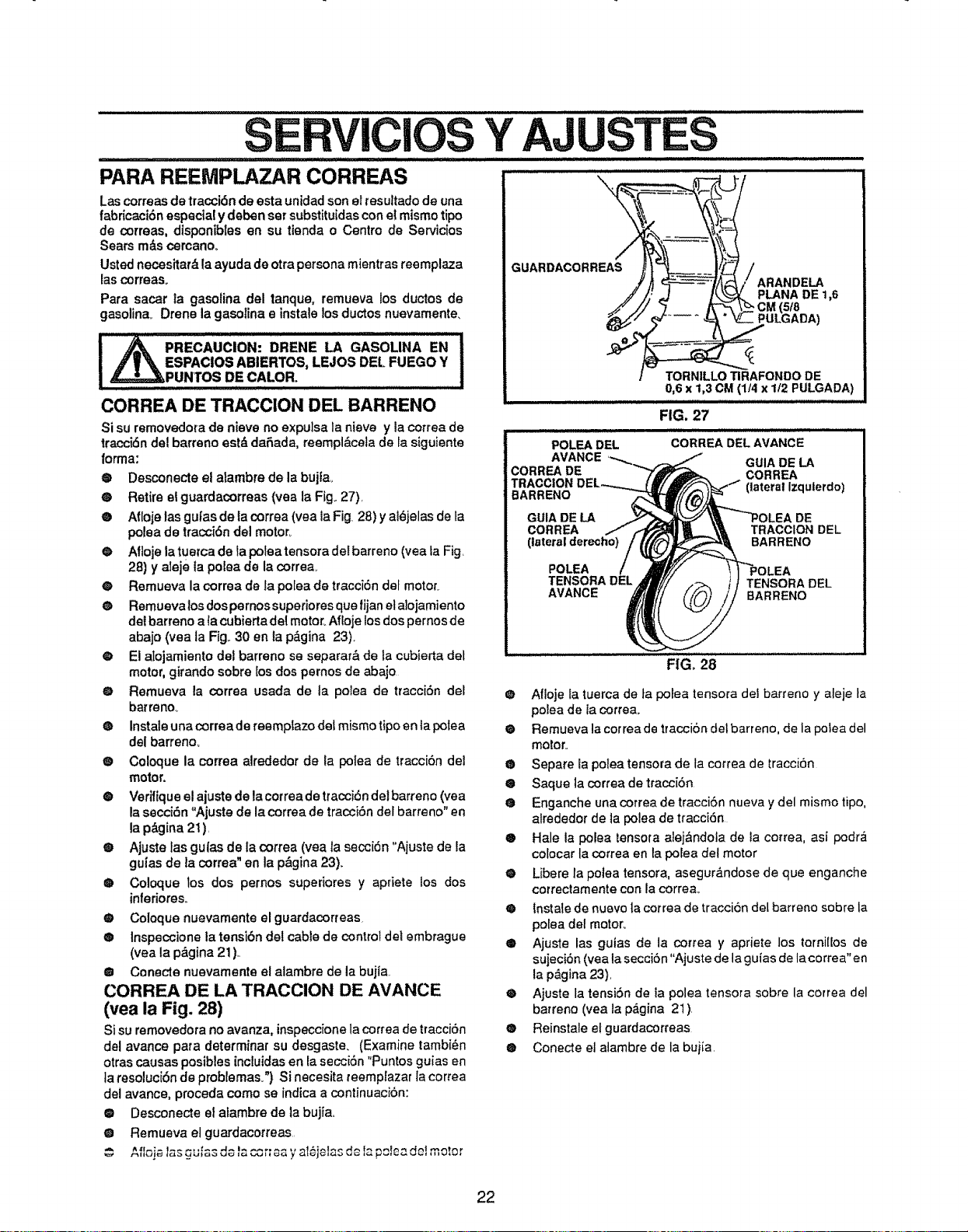
ir ..........
PARA REEMPLAZAR CORREAS
Y AJ
,, ,_,,, j,,,, ,j LIL I] I L , iii I IIILIll I I I IIII I III III IIII
JW/I iilHiilUil liil / _
Las correas de tracci6n de esta unidad son el tesuttado de una
fabricaci6n especial y deben set substituidas con el raisin@tip@
de correas, disponibles en su tienda o Centro de Servicios
Sears m&s cercano_
Usted necesitar_ la ayuda de otra persona mientras reemplaza
(as correaso
Para sacar ta gasolina del tanque, remueva los ductos de
gasolina. Drone la gasotina e instal@los ductos nuevamente,
!_ PRECAUClON: DRENE LA GASOLINA EN I
,f | "_ ESPAClOS ABIERTOS, LEJO$ DEL FUEGO Y
_PUNTOS DE CALOR. ......................................
CORREA DE TRACCION DEL BARREN@
Si su removedora de nieve no expulsa la nieve y la correa de
tracci6n del barren@est_ daSada, reempl&celade la siguiente
/orma:
® Desconecte el alambre de la bujia.,
• Retire et guardacorreas (yea la Fig..27).
• Aft@j@las gufas de la correa (yea la Fig. 28) y al_jelas de ta
polea de tracci6n del motor.
® All@j@la tuerca de la polea tensora det barren@(yea LaFig.
28) y aleje la potea de la correa_
• Remueva la correa de la polea de tracciSn dot motor=
O Remuevalos dospernos superiores que fijan et alojamiento
del barren@a {a cubierta del motor_All@j@los dos pernos de
abajo (yea la Fig..30 en ta p&gina 23).
O El atojamiento del barren@ se separar& de la cubierta del
motor, girando sobre Eosdos pemos de abajo
@ Remueva la correa usada de ta polea de tracci6n del
barreno_
O Instal@una correa de reemptazo deLmismo tip@en ta potea
del barreno_
® Coloque la correa alrededor de la polea de traccibn del
motor.
@ Verifiqueel ajuste de la cotrea de tracci6ndel barren@(vea
la secci6n "Ajuste de la correa de tracci6n det barren@"en
la p_.gina21 ).
® Ajuste las gulas de la correa (yea ta seccibn "Ajuste de la
guias de la correa" en la p&gina 23).
@ Coloque los dos pernos superiores y apriete los dos
in(@dotes.
• Coloque nuevamente elguardacorreas.
® tnspeccione la tensibn del cable de control dot embrague
(yea la p&gina 21 ),.
• Conecte nuevamente el alambre de la bujla
CORREA DE LA TRACCION DE AVANCE
(vea la Fig. 28)
Si su removedora no avanza, inspeccionela correa de ttacci6n
del avance para determinar su desgaste. (Examine tambi_n
otras causas posibles incEuidasen la secci<_n"Puntos guias en
ta resoluciSn de problemas.') Si necesita teemplazar la correa
del avance, proceda corn@se indica a continuaci6n:
@ Desconecte ei alambre de la bujia..
@ Remueva et guardacorreas.
^_,-:..... _._.._^_....... _16ielasdc-Iz,pole_delmotor
GUARDACORREAS
PLANA DE 1,6
)
POLEA DEL CORREA DEL AVANCE
AVANCE GUIA DE LA
CORREADE CORREA
TRACCION (tatera!lzqulerdo)
BARREN@
GUIA DE LA DE
CORREA TRACCION DEL
(lateral derecho) BARREN@
POLEA .EA
TENSORA DEL TENSORA DEL
AVANCE BARREN@
FIG, 28
• Afloje la tuerca de ta polea tensora dei barren@ y aleje la
potea de ta correa.
O Remueva la correa de traccion del barren@,de la potea del
motor.
• Separe la polea tensora de la correa de IracciSn
® Saque la correa de traccibn
• Enganche una correa de tracci6n nueva y del mismo tip@,
atrededor de la polea de tracci6n
e Hale la polea tensora alejbndola de la correa, asi podra
col@carta correa en la porea del motor
• Libere la polea tensora, asegur_ndose de que enganche
correctamentecon la correa.
O Instale de nuevo la correa de tracci6n deLbarren@sobre la
polea del motor°
€ Ajuste las guias de la cortea y apriete los torniffos de
sujeci6n (yea la seccibn "Ajuste de la guias de la correa" en
la p&gina 23),
O Ajuste la tensi6n de la polea tensora sobre la correa del
barren@(vea la p,_gina 21 )
® Reinstale elguardacorreas
• Conecte el alambre de la buiia.
22
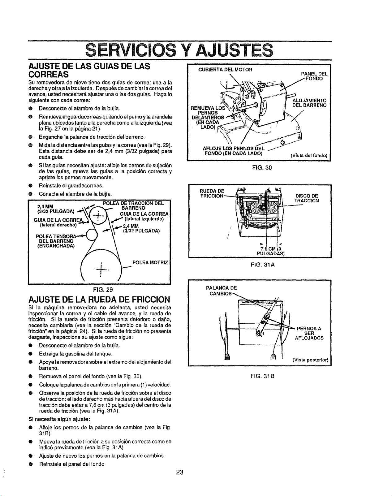
SERVlCiOS Y AJUST .......................................
CUB1ERTADEL MOTOR
AJUSTE DE LAS GUIAS DE LAS
CORREAS
Su removedora de nieve tiene dos gulas de correa: una a la
derechayotraa laizquierda. Despu_s decambiarlacorreadel
avance, usted necesitar& ajustar una o las dos guIas. Haga 1o
siguiente con cada correa:
• Desconecte el alambre de la bujra,
O Remueva el guardacorreas quitando el perno y la arandela
plana ubicadostanto a la derechacomo a la izquierda(vea
la Fig, 27 en la p&gina 21)_
O Enganche ta patanca de tracci6n del barreno_
® Mida la distancia entre las gufas y lacorrea (yea la Fig. 29).
Esta distancia debe ser de 2,4 mm (3F32 pulgada) para
cada gufa..
e Si las gu[as necesitan ajuste: afloje los pernosde sujeci6n
de las gu|as, mueva las guias a la posici6n correcta y
apriete Ios pernos nuevamente
• Reinstale el guardacorreas,.
@ Conecte el alambre de la bujlao
=, .......... ,.,,... <_POLEADSTRAOCiONOEL
, MM BARRENO
(3!32 PULGADA) ae__ GUIA DE LACORREA
GUIA DE LA CORREA_'_= : _ f (lateral izqulerdo)
(lateralderecho) _ - _'_ \;_e.-" 2,4 MM
.OLEATENSO..-"(_)"") _3132PULaADA_
DEL BARRENO _ "t
Q _@,. 1___._ POLEAMOTRIZ
FIG. 29
AJUSTE DE LA RUEDA DE FRICCION
Si la m&quina removedora no adelanta, usted necesita
inspeccionar la correa y el cable de1 avance, y la rueda de
fricci6n, Si ta rueda de fricciSn presenta deterioro o daSo,
necesita cambiarla (yea la secci6n "Cambio de ia rueda de
fricoi6n" en la p&gina 24), Si la rueda de fricci6n no presenta
desgaste, inspeocione su ajuste como sigue:
® Desconecte el alambre de la bujia,
• Extraiga la gasotina deltanque.
• Apoye la removedora sobre el extremo dei alojamiento del
barreno..
PANELDEL
REMUEVA LOS
PERNOS
DELANTEROS
CADA
\
\
AFLOJELOS PERNOSDEL
FONDO(EN CADALADO)
FIG. 30
ALOJAMIENTO
DELBARRENO
(Vista del fondo)
FIG, 31A
PALANCADE
CAMBIOS_
PERNOSA
SER
AFLOJADOS
(Vista posterior)
• Remueva el panef det rondo (yea fa Fig. 30)
• Coloque la palanca decambios en laprimera (1) velocidad.
• Observe la posiciSn de la rueda de friccibn sobre eEdisco
de tracciSn: el lado derecho m&shacia afuera det disco de
tracci6n debe estar a 7,6 cm (3 pulgadas) det centro de la
rueda de fricciSn (vea ]a Fig. 31A)
Sl necesita alg_n aJuste:
• Afloje los pernos de la palanca de cambios (yea ta Fig
319),
I Mueva la rueda de fricciSn a su posiciSn correcta como se
indic6 previamente (vea ]a Fig 3IA)
• Ajuste de nuevo los pernos en la palanca de cambios.
@ Reinstaie elpanel de!rondo
FIG.. 31 B
23
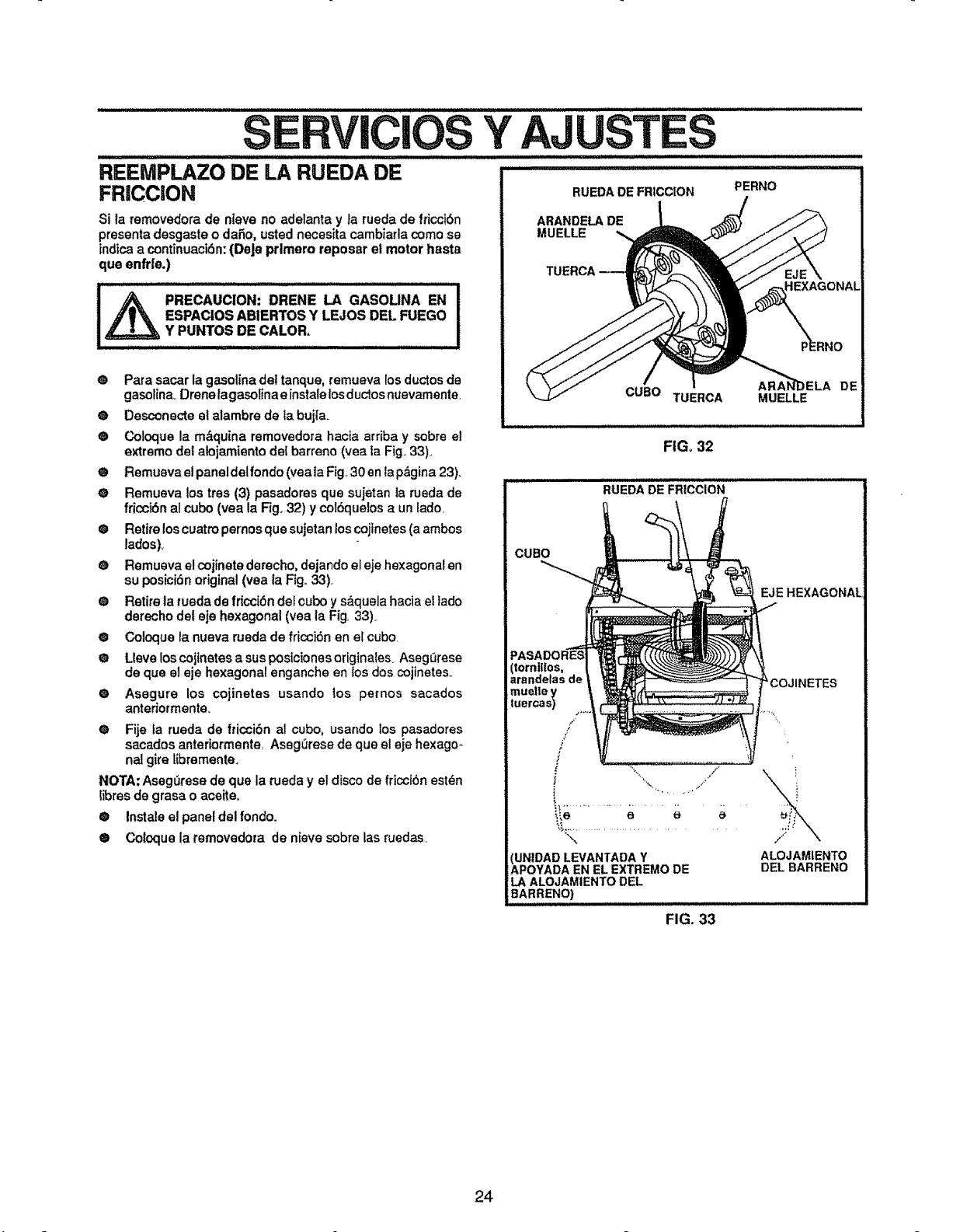
Y AJ TES
PERNO
REEMPLAZO DE LA RUEDA DE
FRICCION
Si la removedora de nteve no adelanta y ta rueda de fricctbn
presenta desgaste o daSo, usted necesita cambiarla come se
indica a continuacidn:(DeJe prlmero reposar el motor haste
qua enfde,)
_ PRECAUCION: DRENE LA GASOUNA EN
ESPAClOS ABIERTOS Y LEJOS DEL FUEGO
Y PUNTOS DE CALOR.
O Para sacar la gasoline del tanque, remueva los ductos de
gasolina_ Drene ta gasoiina e instale losductos nuevamente
O Desconecte el alambre de la buj[a.
O Coloque la m&quina removedora hacia arriba y sobre el
extreme del aloiamiento det bert®no (vea la Fig_33)°
O Remueva el paneldelfondo (veala Fig 30 en lap&gina 23).
O Remueva los tres (3) pasadores que sujetan la rueda de
fricci6n ai cube (vea la Fig. 32) y col6quelos a un lado_
@ Retire los cuatro pernos que sujetan los cojfnetes (a ambos
lados)_
@ Remueva el cojinete derecho, dejando el eje hexagonal en
su posiciSn original (yea la Flg_ 33).
Q Retire la rueda de fricci6n del cube y s_quela hacia el lade
derecho del eje hexagonal (yea la Fig. 33).
@ Coloque la nueva rueda de fricoi6n en el cube
@ Ueve los cojinetes a sus posiciones originates_Aseg_rese
de que el eje hexagonal enganche en los dos cojinetes.
® Asegure los cojinetes usando los pe[nos secedes
antedormente_
® Fije la rueda de fticoi6n al cube, usando los pasadores
secedes anteriormente Asegerese de que el eje hexago-
na! gire tibremente.
NOTA: Aseg_rese de qua la rueda y el disco de fricci6n ®stUn
libres de grasa o aceite,,
® Instal® el panel del rondo.
e Coloque la removedora de nieve sobre las ruedas
RUEDA DE FR;CCtON
CUB® TUERCA
FIGo32
RUEDA DE FRICCION
CUB®
(tornilIos,
arandelasde
muettey
tuercas)
F
/
J
/
"\
(UNtDADLEVANTADA Y
APOYADAEN EL EXTREMODE
LA ALOJAMIENTODEL
iBARREN®) .................................................
DE
MUELLE
EJE HEXAGONAL
,f.'*
ALOJAMIENTO
DEL BARREN®
FIG. 33
24
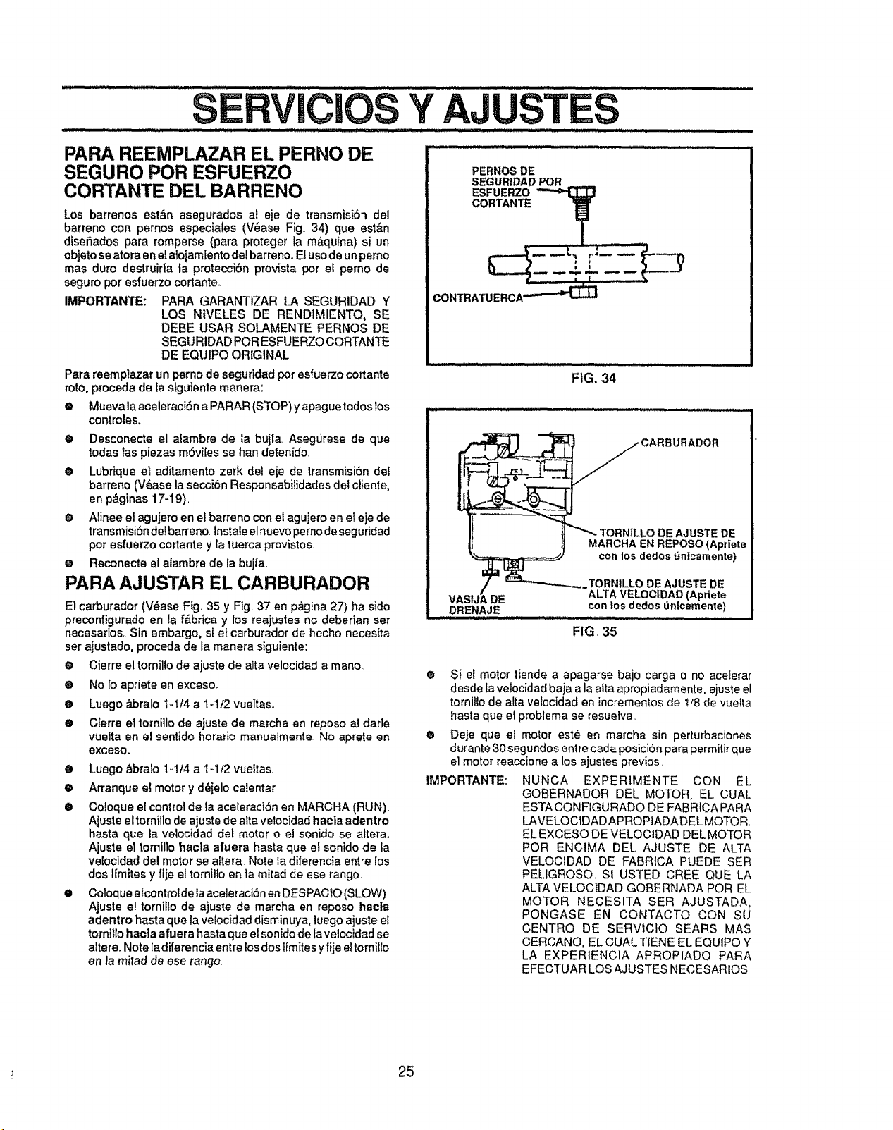
iiiii J,lll,ll,,l,,,,,,, ii ii ... i,,J,ll,,l,,
VlCIOS Y AJ TES
i i i l l,ll,i ii i i i,ll, i i ill Li ,l,i ill Lll i i H,, .................................................................
PERNOSDE
SEGURIDADPOR
PARA REEMPLAZAR EL PERNO DE
SEGURO POR ESFUERZO
CORTANTE DEL BARRENO
Los barrenos est&n asegurados at eje de transmfsi6n del
barreno con pernos especiales (V_ase Fig. 34) que est&n
diseSados para romperse (para proteger la m&quina) si un
objeto se atora en el alojamiento dei barrenoo E!uso de un perno
mas duro destruir|a ta protecci6n provista pot el perno de
seguro pot esfuerzo cortante.
IMPORTANTE: PARA GARANTIZAR LA SEGURIDAD Y
LOS NIVELES DE RENDIM1ENTO, SE
DEBE USAR SOLAMENTE PERNOS DE
SEGURIDAD POR ESFUERZO CORTANTE
DE EQUIPO ORIGINAL
Para reemplazar un perno de seguridad por esfuerzo cortante
roto, proceda de la siguiente manera:
o Mueva la aceleraci6n a PARAR (STOP) y apague todos los
controles.
• Desconecte el alarnbre de la buj|a Aseg0rese de que
todas fas piezas rn6vi[es se han detenido.
e Lubrique el aditamento zerk det eje de transmisiSn dee
barreno (V_ase la secciSn Responsabitidades del cliente,
en p&ginas 17-19)
• Alinee el agujero en el barreno con ei agujero en el eje de
transmisiSn delbarreno instale el nuevo perno de seg uridad
pot esfuerzo cortante y Ia tuerca provistos.
e Reconecte el alambre de Eabuj|a.
PARA AJUSTAR EL CARBURADOR
El carburador (V_ase Fig_35 y Fig 37 en p_gina 27) ha sido
preconfigurado en la f&brica y los reajustes no debedan set
necesarios. Sin embargo, si el carburador de hecho necesita
ser ajustado, proceda de la manera siguiente:
e Cierre el tornillo de ajuste de alta velocidad a mano.
e No Io apriete en exceso.
@ Luego _.brato 1-1/4 a 1-1/2 vueltaso
@ Cierre el torniUo de ajuste de marcha en reposo al darle
vuelta en el sentido horatio manualmente No aprete en
exceso.
• Luego &bralo 1-1t4 a I-1t2 vueltas
e Arranque el motory dejelo calentar
e Coloque el control de ta aceteraci6n en MARCHA (RUN)
Ajuste el tornillo de ajuste de alta velocidad haela adentro
hasta que la velocidad del motor o el sonido se altera
Ajuste el tornillo hacla afuera hasta que el sonido de ta
ve!ocidad del motor se altera Note la diferencia entre los
dos lfmitesy fije el tornilto en la mitad de ese tango
• Coloque elcontro|de laaceleraci6n en DESPACIO (SLOW)
Ajuste el tornillo de ajuste de marcha en reposo hacla
adentro hasta que ta vetocidad disminuya, luego ajuste el
torniilo hacla afuera hasta que el sonido de laveiocidad se
altere. Note ladiferencia entre losdos lfmites y fije el torniUo
en la mitad de ese rango
CONTRATUERCA _
FIG, 34
CARBURADOR
DE AJUSTE DE
MARCHA EN REPOSO {Apriete
con los dedos _ntcamente)
TORNILLODE AJUSTEDE
ALTAVELOCIDAD(Apriete
DE con los dedos_nicamente)
DRENAJE
FIG,, 35
O
o
IMPORTANTE:
Si et motor tiende a apagarse bajo carga o no aceterar
desde ta velocidad baja a la atta apropiadamente, ajuste el
tornitio de atta velocidad en incrementos de !/8 de vuelta
hasta que el problema se resuelva
Deje que et motor est_ en marcha sin perturbaciones
d_rante 30 segundos entre cada posicionpara permitir que
el motor reaccione a los ajustes previos
NUNCA EXPERIMENTE CON EL
GOBERNADOR DEL MOTOR, EL CUAL
ESTA CONFIGURADO DE FABRtCA PARA
LAVELOCIDADAPROPIADADEL MOTOR.
EL EXCESO DE VELOCIDAD DEL MOTOR
POR ENCIMA DEL AJUSTE DE ALTA
VELOClDAD DE FABRICA PUEDE SER
PELIGROSO SI USTED CREE QUE LA
ALTA VELOCIDAD GOBERNADA POR EL
MOTOR NECESITA SER AJUSTADA,
PONGASE EN CONTACTO CON SU
CENTRO DE SERVtCIO SEARS MAS
CERCANO, EL CUAL TIENE EL EQUIPO Y
LA EXPERIENCIA APROPIADO PARA
EFECTUAR LOS AJUSTES NECESARIOS
25
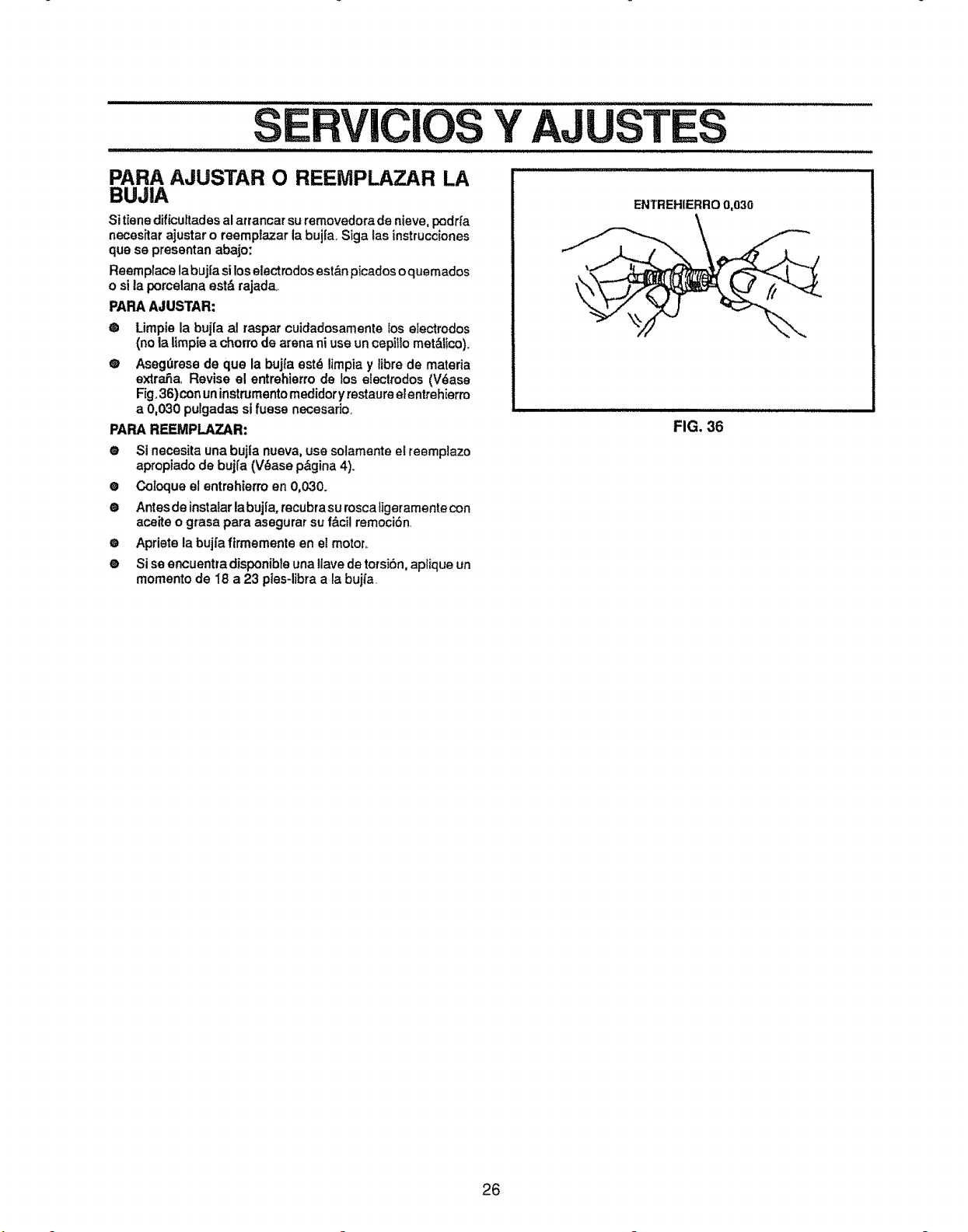
SERVICIOS Y AJ
i=l=l=l=l=,l,m,ll,=,,,i=l=l=i=l=l=i i ,l,llll,l,lli i
u,,,,l,t i,,,,ii,,,, ,11,,,,,,,,,11,i J,
TES
PARA AJUSTAR O REEMPLAZAR LA
BUJIA
Si tiene dificuttades al arrancar su removedora de nieve, podr_a
neces_tarajustar o reemplazar la buj[a. Siga las instrucciones
que se presentan abajo:
Reemplace la buj[a si los electrodosest&rt picados o quemados
o si la porcelana est_ rajada,,
PAPA AJUSTAR:
@ Limpie la bujIa al raspar cuidadosamente los e_ectrodos
(no la Umpiea chorrode arena ni use un cepi_lomet&iico)_
@ Aseg_rese de que la buj|a est_ limpia y libre de mateda
extra, a, Revise el entrehierro de los electrodos (V6ase
Rg.36 ) con un instrumento medidor yrestaure er entrehierm
a 0,030 pulgadas sJ fuese necesario.
PARA REEMPLAZAR:
e Si necesita una bujla nueva, use solamente el reemplazo
apropiado de bujl'a (V_ase p_gina 4).
• Coloque et entrehierro en 0,030.
• Antes de instalar la bujia, recubrasu rosca ligeramente con
aceite o grasa para asegurar su f&cil remoci6n
o Apriete la bujfa firmemente en el motor..
® Si so encuentra disponible una ltave de torsiSn, aplique un
momento de 18 a 23 pies-libra a la bujfa.
ENTREHIERRO 0,030
FIG. 36
26
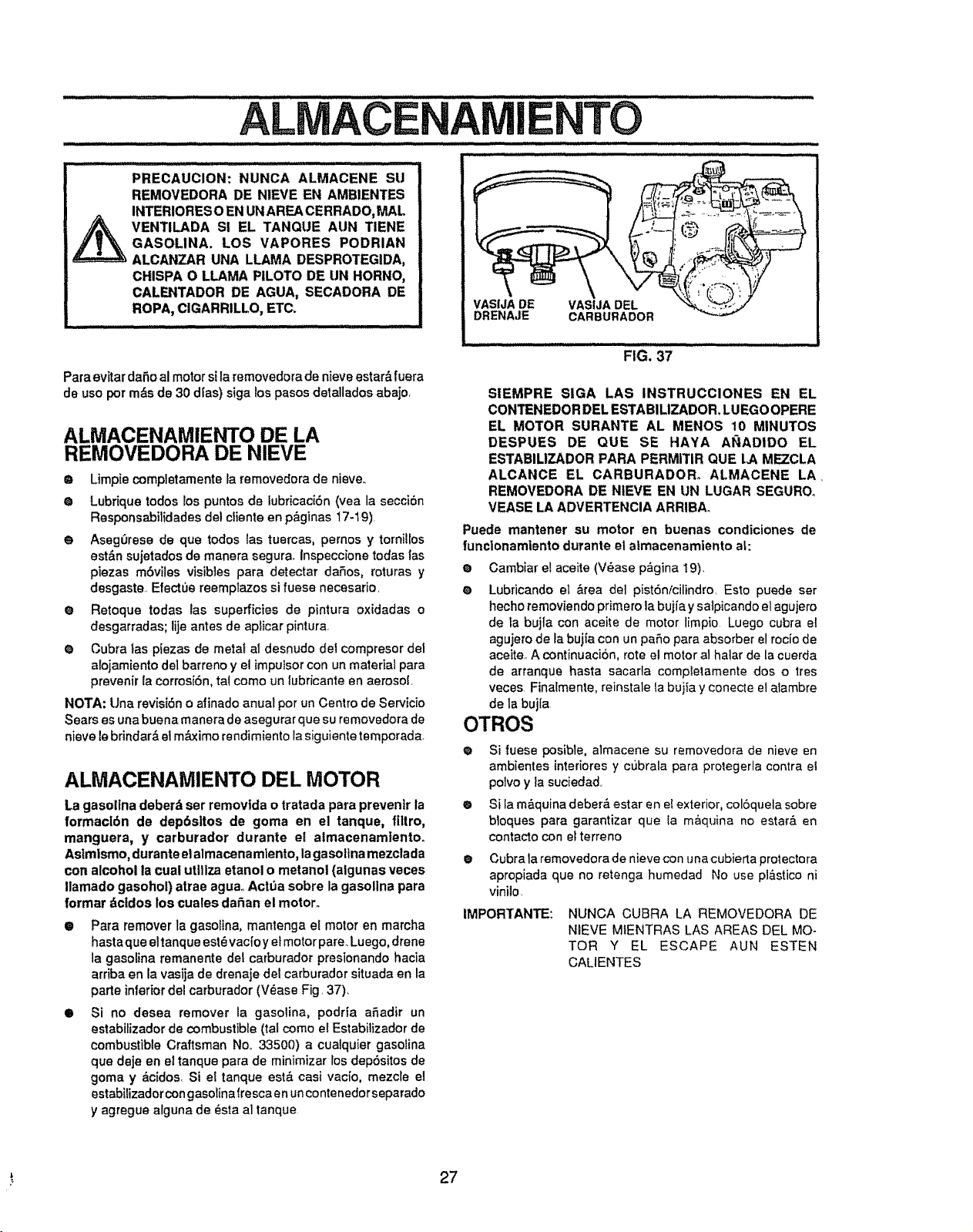
PRECAUCION: NUNCA ALMACENE SU
REMOVEDORA DE NIEVE EN AMBIENTES
INTERIORES O EN UN AREA CERRADO, MAL
VENTILADA S! EL TANQUE AUN TIENE
GASOLINA. LOS VAPORES PODRIAN
ALCANZAR UNA LLAMA DESPROTEGIDA,
CHISPA O LLAMA PILOTO DE UN HORNO,
CALENTADOR DE AGUA, SECADORA DE
ROPA, ClGARRILLO, ETC.
Para evitar daSo al motor sila removedora de nieve estar& fuera
de use per m_s de 30 dlas) siga los pasos detallados abajo,
ALMACENAMIENTO DE LA
REMOVEDORA DE NIEVE
O Limpie completamente la removedora de nieve..
O Lubrique todos los puntos de lubricaci6n (vea la secci6n
Responsabilidades del cliento en p_ginas !7-19)
O Aseg_rese de que todos las tuercas, pernos y tornillos
est&n sujetados de manera segura. Inspeccione todas las
piezas mbviles visibles para detectar dales, roturas y
desgaste. Electue reemplazos si fuese necesario.
O Retoque todas las superficies de pintura oxidadas o
desgarradas; lije antes de apiicar pintura.
Q Cubra las piezas de metal al desnudo del compresor del
alojamiento del barreno y el impuIsor con un material para
prevenir la corrosiSn, tal come un lubricante en aerosol.
NOTA: Una revisi6n o afinado anual per un Centre de Servicio
Sears es una buena manera de asegurar que su removedora de
nieve le brindar& el m_imo rendimiento la siguiente temporada.
ALMACENAMIENTO DEL MOTOR
VASIJA DE VAStJA DEL
DRENAJE CARBURADOR
FIG. 37
SiEMPRE SIGA LAS INSTRUCCIONES EN EL
CONTENEDOR DEL ESTABlUZADOR. LUEGO OPERE
EL MOTOR SURANTE AL MENOS 10 MINUTOS
DESPUES DE QUE SE HAYA Af_ADIDO EL
ESTABILIZADOR PARA PERMiTIR QUE I.A MEZCLA
ALCANCE EL CARBURADOR° ALMACENE LA.
REMOVEDORA DE NIEVE EN UN LUGAR SEGURO.
VEASE LA ADVERTENCIA ARRIBAo
Puede mantener su motor en buenas condiciones de
funclonamiento durante el atmacenamiento aL:
o Cambiar el aceite (V_ase p_gina t9)_
• Lubricando el &tea det pist6nicilindro, Esto puede ser
hecho removiendo pdmero ta buj[a y salpicando el agujero
de ta bujta con aceite de motor limpio Luego cubra et
agujerode la bujfa con un pale para absorber el rocio de
aceite A continuaci6n, rote el motor al halar de la cuerda
de arranque hasta sacarla completamente dos o tres
veces Finalmente, reinstale la bujia y conecte el atambre
de la bujla.
OTROS
O
La gasollna deber& ser removlda o tratada para preventr la e
formacl6n do dep6sltos de goma en el tanque, flltro,
manguera, y carburador durante el almacenamlento.
Astmlsmo, durante el almacenamlento, la gasoltna mezclada O
con alcohol la cual uttllza etanol o metanol (algunas veces
Ilamado gasohol) atrae agua.,Actt_a sobre la gasollna para
format dcldos los cuales da_an el motor°
@
Para remover la gasolina, mantenga el motor en marcha
hasta que eltanque est_ vaclo y el motor pare_Luego, drene
la gasolina remanente det carburador presionando hacia
ardba en la vasija de drenaje del carburador situada en la
parle inferior del carburador (V_ase Fig. 37).
O
Si fuese posible, almacene su removedora de nieve en
ambientes interiores y cubrata para protegerla contra el
polvo y ta suciedad,
Si la m&quina deber__ estar en el exterior, col6quela sobre
bloques para garantizar que la m_quina no esta_& en
contacto con et terreno
Cubra la removedora de nieve con una cubierta protectora
apropiada que no retenga humedad No use pl&stico ni
vinilo.
IMPORTANTE:
Si no desea remover la gasolina, podrTa aSadir un
estabilizador de combustible (tal come el Estabilizador de
combustible Craftsman No. 33500) a cuatquier gasoIina
que deje en el tanque para de minimizar los dep6sitos de
goma y dcidos. Si el tanque est& casi vaclo, mezcle el
estabilizador con gaso_inafrescaen un contenedorseparado
y agregue afguna de dsta al tanque
NUNCA CUBRA LA REMOVEDORA DE
NBEVEMIENTRAS LAS AREAS DEL MO-
TOR Y EL ESCAPE AUN ESTEN
CALIENTES
27
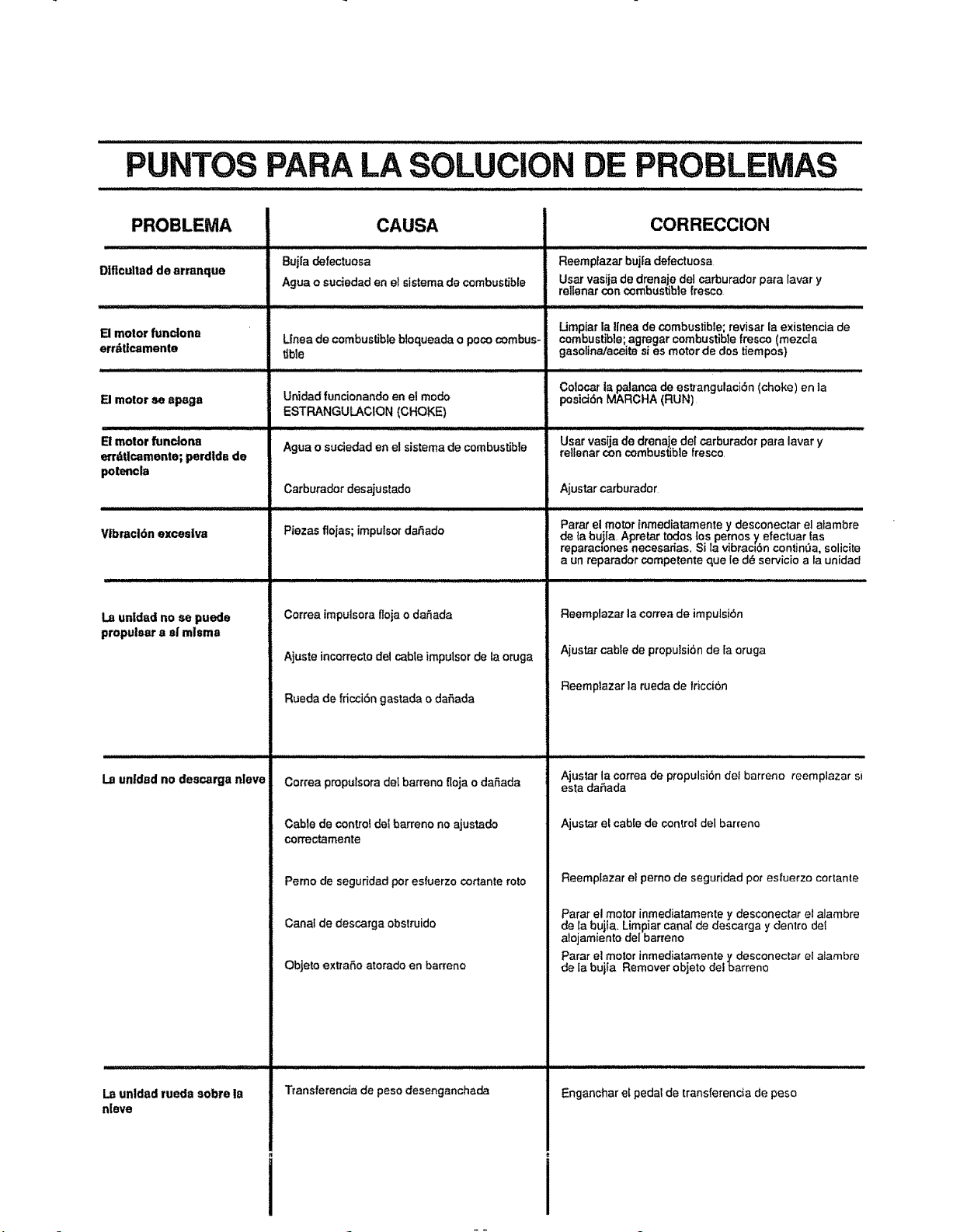
PUNTOS PARA LA SOLUCION DE PROBLEMAS
PROBLEMA
Dlflcultad de arranque
El motor fundonn
errdtlcamente
El motor ereapaga
B motor fundona
ertdtlcamente; perdldB de
poten¢la
CAUSA
Bujra defectuosa
Ague o suciedad en el sistema de combustible
Llnea de combustible btoqueada o poco combus-
tible
Un]dad funcionando en el mode
ESTRANGULACION (CHOKE)
Agua o suciedad en el sistema de combustible
Carburador desajustede
Piezas floias; impulsot da_ado
V|brac|6n exceslva
La un|dad no se puede
propulsar a st' mlsma
Correa impulsora floja o daSada
Ajuste incorrecto del cable impulsor de la oruga
Rueda de fdcci6n gastada o dafada
La unldadno descarga nleve
untded rueda sobre la
nleve
Correa proputsora de[ barreno floja o dafada
Cable de control del barreno no ajustade
correctamente
Perno de seguridad per esfuerzo cortante rote
Canat de descarga obstruido
Objeto extraSo atorado en barreno
Transferencia de peso desenganchada
CORRECClON
Reempfazar bujfa defectuosa
User vasija de drenaje del carburador pate laver y
relIenar con combustible fresco
Limpiarla Ifnea de combustible; reviser la existencia de
combustible; agregar combustible fresco (mezcla
gasolina/aceite si es motor de dos tiempos)
H,,,p, , =,,1==1, ,
Colocar la palanca de es_'angulaci6n (choke) en la
posici6n MARCHA (RUN)
User vasija de drenaje del carburador pate laver y
rellenar con combustible fresco
Ajustar carburader
Parer el motor inmediatamente y desconectar el atambre
de tabui[a, Apretar redes los pernos ,/efectuar {as
reparaoJones necesedas, Si Ia vibraQbn contin0a, solicite
a un reparador competente que le d_ servicio ala unidad
Reemplazat la correa de impulsi6n
Ajustar cable de proputsidnde {a oruga
Reempfazar la rueda de friccibn
Ajustar la correa de propulsiSn deI barreno reemplazar sl
esta daSada
Ajustar el cable de control del barreno
Reemplazar el perno de seguridad pot esfuerzo cortante
Parer et motor inmediatamente y desconectar e! alambre
de {a bujla. Limpiar canal de descarga y dentro det
alojamiento del barreno
Parar ei motor inmediatamertte ydesconecta_ el alambre
de Eabui{a Remover objeto det barreno
Enganchar el pedal de transferencia de peso

NOTAS
29

NOTAS
30

.............I'HH Illll I I I
NOTAS
31
MANUAL DEL
PROPIETARIO
MODELO NO.
536.886121
COMO EFECTUAR
EL PEDIDO DE
PIEZAS DE
REPUESTO
PARA SERVICIO DE
REPARACIONES LLAME GRATIS AL
1-800-4=REPAIR
(1-800-473-7247)
PARA OBTENER INFORMACION
SOBRE LAS PARTES DE
REPUESTO Y PARA ORDENAR
LLAME A ESTE NUMERO GRATIS:
1-800-FON-PART
(1-800-366-7278)
SI NECESITA SABER LA
UBICACION DEL CENTRO DE
SERVICIO DE REPARACIONES
SEARS EN SU AREA LLAME 24
HORAS AL DIA, 7 DIAS A LA
SEMANA AL:
1-800-488=1222
SEARS,
5 CABALLOS
MRN
DE FUERZA
DOS ETAPAS,56 CM
(22 PULGADAS)
REMOVEDORA DE NIEVE
ARRANQUE ELI_CTRICO
Cada REMOVEDORA DE NIEVE tiene su propio
NUMERO DE MODELO en el marco de montaje
del motor,
Cada MOTOR tiene su propio NUMERO DE
MODELO en el ALOJAMIENTO DEL
COMPRESOR,
Siempre mencione estos NUMEROS DE MODELO
cuando solicite servicio o piezas de repuesto para
su REMOVEDORA DE NIEVE
Todas las piezas se pueden pedir a trav_s de los
Centros de servicio de Sears, Roebuck and Com-
pany y la mayorfa de Tiendas al detalle
AL EFECTUAR UN PEDIDO DE PIEZAS,
SIEMPRE
PROVEA LA SIGUIENTE INFORMACION:
® PRODUCTO - "REMOVEDORA DE NIEVE"
• NUMERO DE MODELO - 536.886121
• NUMERO DE MODELO DEL MOTOR -
. 143.965003
® NUMERO DE PIEZA
® DESCRIPCION DE LA PIEZA
"Su mercaderia Sears posee valor agregado cuando usted
considera que Sears tiene unidades de servicio a nivel
nacional con personal t_cnico capacitado pot
Sears_.,T_cnicosprofesionales capacitados especfficamente
en productos Sears, tenemos las piezas, las herramientas
y el equipo para garantizar que cumplimos con nuestra
promesa al cfiente..le proporcionamos servicio a lo que
vendemos;'
ROEBUCK AND CO., Hoffman Estates, IL 60179
Impreso en los EE,UU
32


