Loading ...
Loading ...
Loading ...
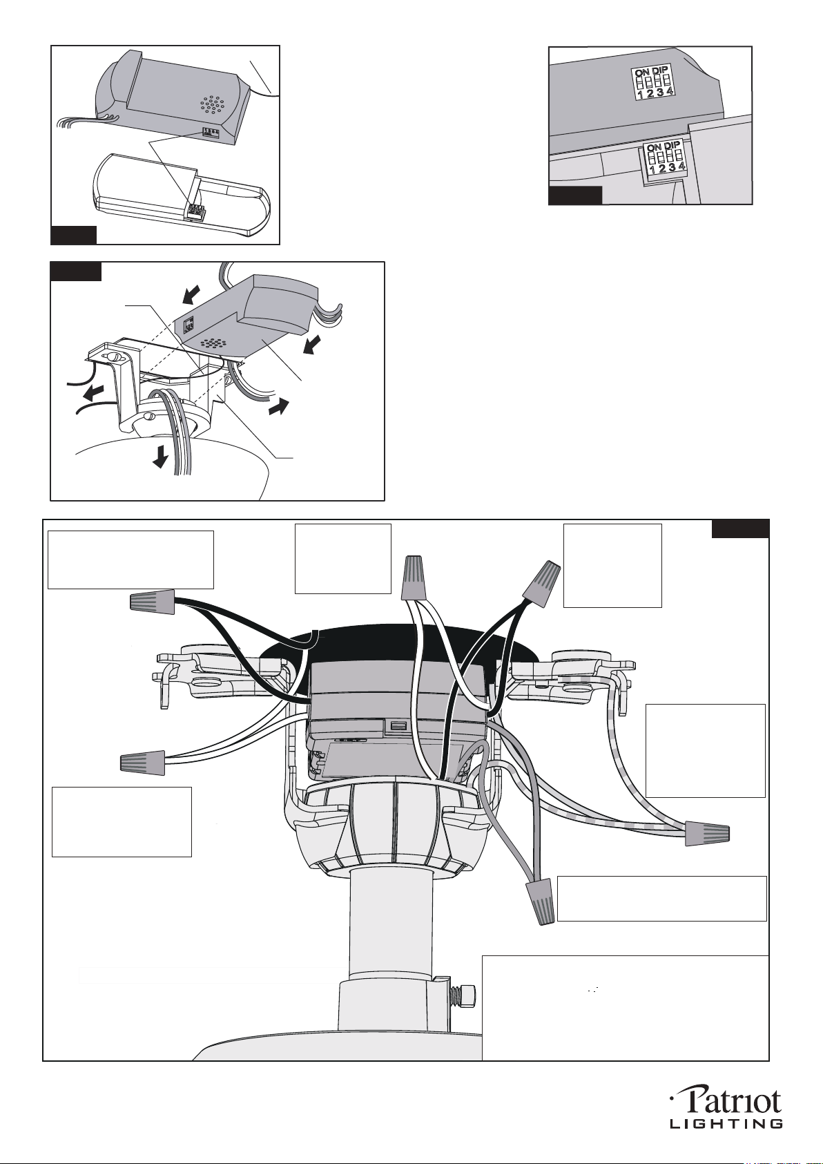
Fig.11
Move Ground Wires (a), Outlet Box wires (b), and
Motor Wires (c) away from the center of the Hanger
Bracket. Then slide Receiver through Hanger
Bracket as shown, Antenna end first, until it is
centered. Finally, cut Motor Wires (c) to length
needed for connections.
Antenna
Receiver
Hanger Bracket
a.
b.
c.
PAGE: 6 / 11
Code example:
1-ON 2-OFF 3-ON 4-OFF on both DIP
Switches.
Note: If you have two ceiling fans
with 2 remote control units, set 2
different codes for each set of
transmitter / receivers.
Fig.10a
Fig.10
Antenna
DIP Switch
Transmitter
Receiver
There is a code switch in the transmitter
and receiver. This "DIP Switch" is a 4 key
unit (Fig.10). All keys were set at "ON"
position in the beginning. Set the keys to
a different code. Make sure the same
numbered keys are switched "ON" for
both DIP Switches (Fig.10a). Take note
that the "ON" position may have different
orientation in each.
Grounding
Green
Green
Black
Black
Black
Black
Connect the white
wire from Receiver
to the white wire
from motor with a
wire connector.
Connect the black
wire from Receiver
to the black wire
from motor (This is
for fan control) with
a wire connector.
White
White
White
White
Blue
Blue
Connect the blue wire from receiver to the
blue wire from motor (This is for light
control) with a wire connector.
Connect three
ground wires (green,
or bare copper) coming
from outlet box,
downrod and hanging
bracket with a wire
connector.
Connect the white (neutral)
wire from receiver to the
white (neutral) wire from the
outlet box with a wire
connector.
Connect the black (hot) wire
from receiver to the black (hot)
wire from outlet box with a wire
connector.
*** The wire connection points should be turned upward
and pushed carefully up into outlet box.
*** After making the wire connections, the wires should
be spread apart. The white (neutral) conductor and
green (grounding) conductor on one side and the
black (hot) conductor and blue (light) conductor on
the other side of the outlet box.
Fig.12
191227
Loading ...
Loading ...
Loading ...