Loading ...
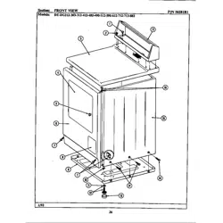
2
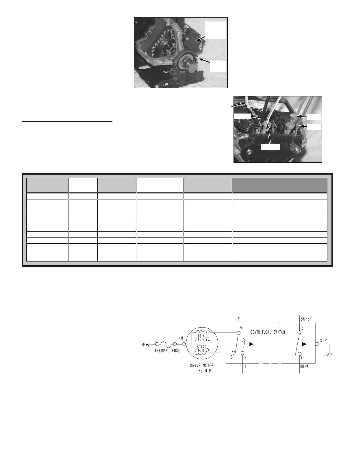
5. Position motor as show in Figure 3. Align
the tab of the motor to the slot of the motor
bracket. Note the location of the motor
switch (switch orientation may vary).
WIRING INSTRUCTIONS
6. Follow Figure 4 and the chart below to assure proper installation of replacement
motor.
NOTE: When reterminating connections, cut lead wire as close to the terminal as
possible and strip wires back approximately 1/4”. Using barrel crimpers, crimp the
1/8” insulated female terminals, supplied with the motor, onto the appropriate leads.
FIGURE 3
NOTE
SWITCH
LOCATION
MOTOR
CLAMP
W10408722B
GAS or ELECTRIC DRYERS
FIGURE 4
YELLOW (6)
GREY (1/4”
PROTECTOR
TAB)
RED (5)
BLUE (1)
BLACK (2)
EET, JAJ & MWM Electric
Old Motor Discrete
Connect Switch
Exisng Machine
Harness
New Service Motor Plug-
Connect Switch
Acon
Terminal No. Funcon Color Code Comments Terminal Number
Grey L1 Grey
1/4" Thermal Protector
Tab
Remove and discard Blue Jumper Lead between
Switch Terminal 4 and 1/4" Protector Tab,
connect Grey Harness lead to 1/4" Protector Tab
5deRlartueNdeR
Reterminate Red Lead with 1/8" Insulated
Terminal and Connect to Switch Tab 5
tcennoC1eulBretaeH*Blue (& White) to 1/4" Tab 1
tcennoC2kcalBretaeH**Black (& Brown) to 1/4" Tab 2
***Yellow PushToStart Yellow
Oponal (not present in
machines with
Electronic Controls)
6
Reterminate Yellow Lead with 1/8" Insulated
Terminal and Connect to Switch Tab 6
EET, JAJ & MWM Gas
Old Motor Discrete
Connect Switch
Exisng Machine
Harness
New Service Motor Plug-
Connect Switch
Acon
Terminal No. Funcon Color Code Comments Terminal Number
Grey L1 Grey
1/4" Thermal Protector
Tab
Remove Blue Jumper Lead between Switch
Terminal 4 and 1/4" Protector Tab , connect Grey
Harness lead to 1/4" Protector Tab
5deRlartueNdeR
1eulBretaeHeulB
tcennoC2kcalBretaeHkcalB to 1/4" Tab 2
Yellow PushToStart Yellow
Oponal (not present in
machines with
Electronic Controls)
6
Reterminate Yellow Lead
with 1/8" Insulated
Terminal and Connect to Switch Tab 6
Reterminate Red and Blue Leads in the same 1/8"
Insulated Terminal and Connect to Switch Tab 5.
Connect the Blue Lead to 1/4" Tab 1.
* Some model dryers will have a white wire joined with the blue wire. Leave them connected and connect to the same terminal.
** Some model dryers will have a brown wire joined with the black wire. Leave them connected and connect to the same terminal.
*** Dryer models with a Push-To-Start Switch will have a yellow wire. If there is no yellow wire leave this terminal without a connection.
7. Reconnect ground wire.
8. Allleadconnectionsarenishedatthispoint,nishreassemblingdryer.
9. Replace all parts and panels.
© Whirlpool Corporation 2013
(All Rights Reserved)
New Replacement Motor Wiring:
1. Switch connection #5 is a direct connection to the main/run winding and to the centrifugal switch common.
2. Switch connection #3 is a direct connection to the phase/ start winding and to the normally closed contact of the centrifugal switch.
3. Switch connection #6 is the centrifugal switch normally open contact.
4. Switch connections #1 and #2 are the normally open heater contacts.
5. Switch connection #4 is simply a junction point, not connected to anything.
Loading ...
Loading ...