OVERVIEW
Screwdriver and Pliers.
TOOLS REQUIRED
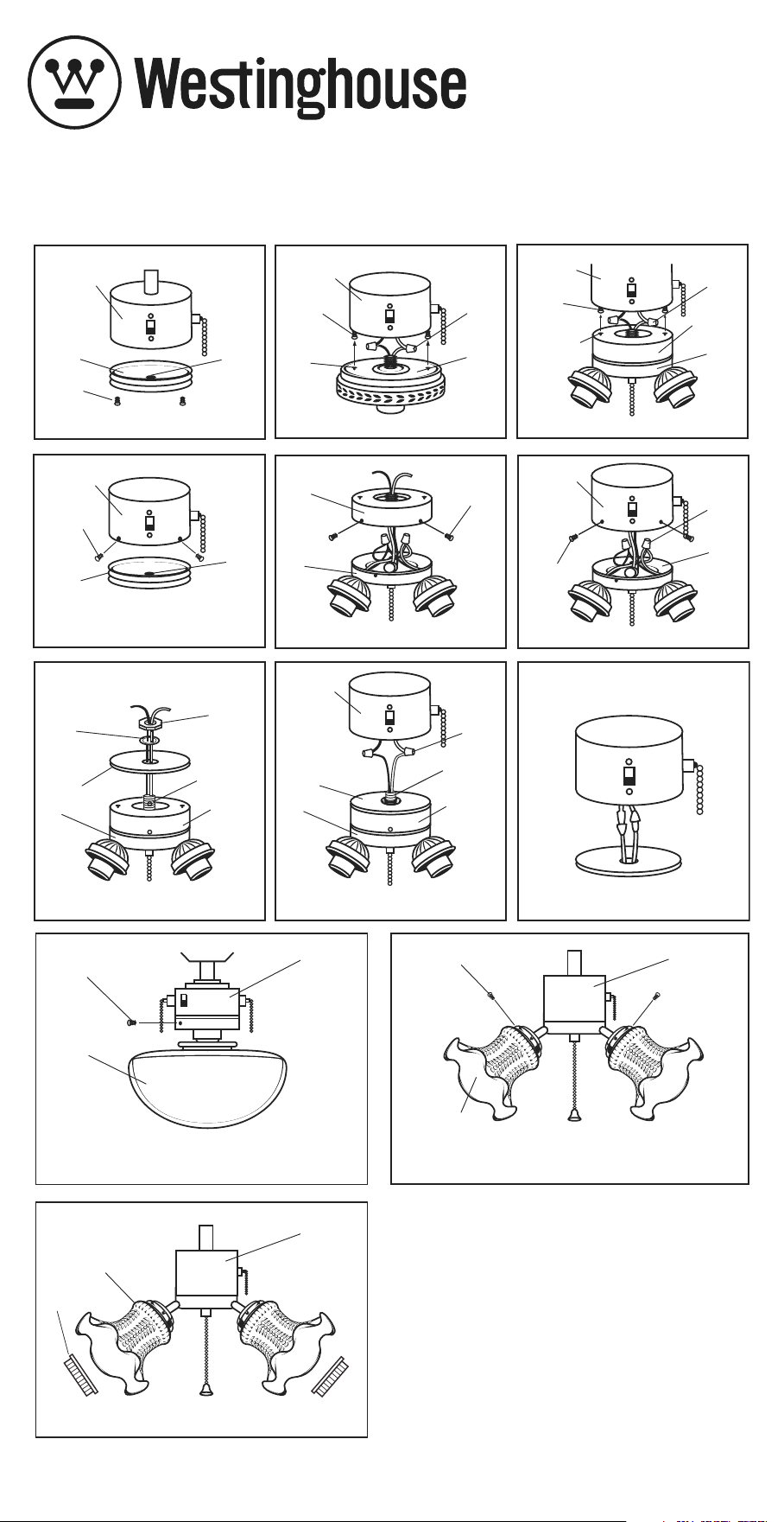
1. Remove the switch housing cover from the fan by unscrewing the screws. You may
keep this cover for future use (See figure 4).
2. Remove adapter cup from top of the light kit by removing the screws on the side of the
light kit (See figure 5).
3. Locate two single wires in switch housing, white (gray on some models) and blue (red on
some models) labeled “for light”.
4. Connect these wires to the light kit wires using the wire nuts already attached
(See figure 6). White (gray) to white and blue (red) to black.
5. NOTE: For French Canadian specs, please use the plug system (See figure 9a).
If using with a UL spec fan, please cut off plugs, and wire with wire nuts provided with fan.
6. Carefully push the wiring connections back into the switch housing.
7. Using the cover plate mounting screws from step 1, attach the flush adapter portion of
light to the switch housing (See figure 6).
8. Proceed to “Shade Installation”.
INTEGRAL INSTALLATION
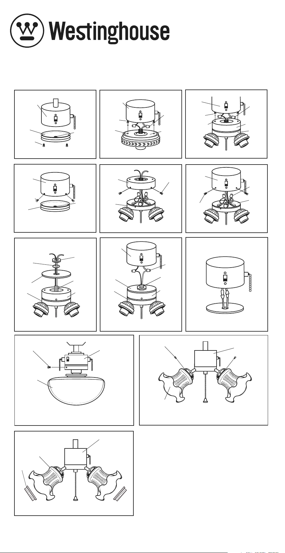
1. Remove the switch housing cover from the fan by unscrewing the screws (See figure 1).
You may keep this cover for future use.
2. Replace the two screws but thread only halfway into the switch housing.
3. Locate two single wires in the switch housing, white (gray on some models) and blue
(red on some models) labeled “for light”.
4. Connect these wires to the light kit wires using the wire nuts already attached
(See figure 2 or 3). White (gray) to white and blue (red) to black.
5. NOTE: For French Canadian specs, please use the plug system (See figure 9a). If
using with a UL spec fan, please cut off plugs, and wire with wire nuts provided with the fan.
6. Carefully push all wires back into switch housing of fan. Attach the light kit by aligning
its keyhole slots with the two screws previously threaded halfway into the switch housing
(See figure 2 for single light kits and figure 3 for 3, 4 or 5 lights). Push up so the screws go
through the light kit's keyhole slots and twist so that the screws engage into the smaller
end of the slots. Tighten the screws securely to prevent light kit from vibrating loose.
7. Proceed to “Shade Installation”.
KEY HOLE INSTALLATION
1. Remove the switch housing cover from the fan by unscrewing the bottom mount
screws (figure 1) or the side mount screws (figure 4).
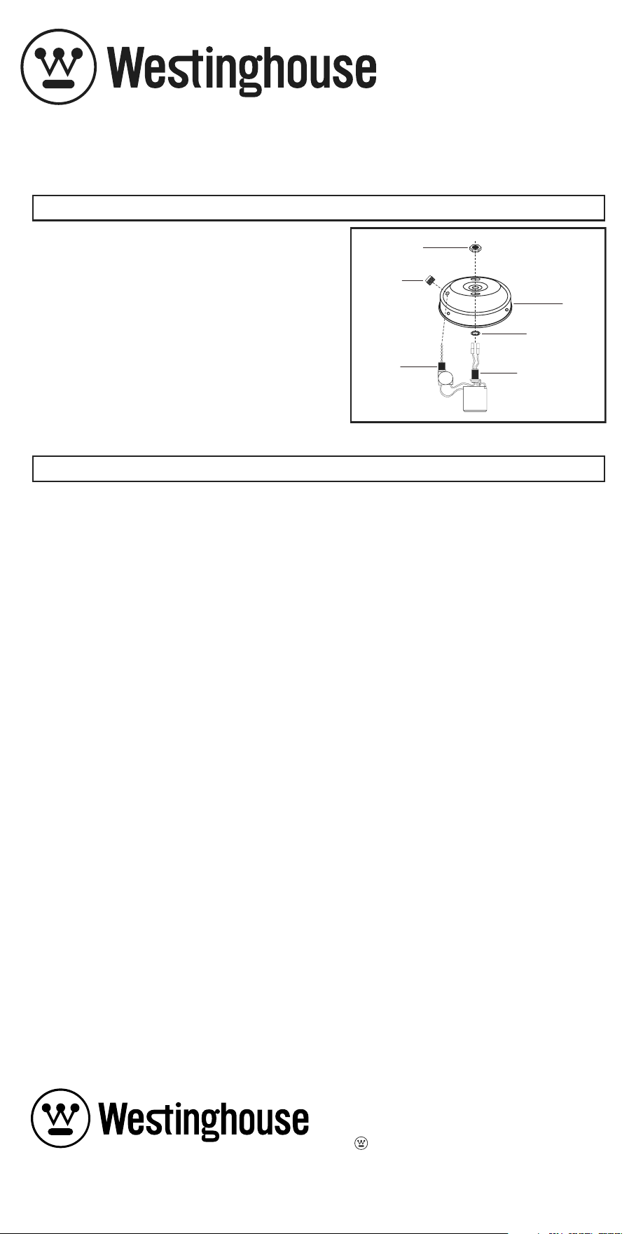
2. Remove the plug (figure 4) from the center of this cover by unscrewing or pushing out.
You may discard the plug.
3. Attach the cover to the light kit threaded tube by first feeding the light kit wires (black and
white) through the hole in the cover and then screwing the cover onto the threaded tube
(See figure 7). Be sure it is tight enough to prevent the light kit from vibrating loose.
4. Place the lock washer and hex nut over the light kit wires onto the threaded tube, and
tighten the screw nut. (See figure 7).
5. Locate two single wires in switch housing, white (gray on some models) and blue
(red on some models) labeled “for light”.
6. Connect these wires to the light kit wires using the wire nuts already attached
(See figure 8). White (gray) to white and blue (red) to black.
7. NOTE: For French Canadian specs, please use the plug system (See figure 9a). If
using with a UL spec fan, please cut off plugs, and wire with wire nuts provided with fan.
8. Carefully push all wires back into the fan’s switch housing. Replace the cover with the
screws removed in step 1.
9. Proceed to “Shade Installation”.
UNIVERSAL INSTALLATION - Center Nipple Attachment
Please refer to the installation that corresponds to your light kit.
NOTE: Turn off power at circuit box to avoid possible electric shock.
For single shade models as seen in figure 9b.
Install light bulb included. Do not over tighten. Use 60 watt maximum medium base light
bulb. Attach shade to light kit shade holders by finger tightening three thumb screws. To
avoid breakage, do not over tighten. Restore electrical power. Installation is complete.
For three shade models by using fitter screw installation as seen in figure 10.
Install shades to light kit shade holders by finger tightening three sets of screws for each
shade holder. To avoid glass breakage, do not over tighten. Install A15 or T2 medium base
light bulbs. Do not over tighten. Use 60 watt maximum bulbs per socket. Restore electrical
power. Installation is complete.
For three shade models by using socket ring installation as seen in figure 11.
Install shades to light kit shade holders by securing three socket rings for each shade
holder. To avoid glass breakage, do not over tighten. Install A15 or T2 medium base light
bulbs. Do not over tighten. Use 60 watt maximum bulbs per socket. Restore electrical
power. Installation is complete.
SHADE INSTALLATION
There are three different types of installations described below. Please read each one
carefully to determine the best method for installing your light kit.
Key Hole Installation
The key hole refers to slots in the light kit adapter in which screws mounted to the bottom
of the switch housing are inserted into these holes (See figures 2 and 3). The adapter
is then turned, locking the screws, and the screws are tightened. Please refer to the
Installation Instructions titled Key Hole Installation.
Universal Installation – Center Nipple Attachment
The universal installation usually works on all fans. This method uses the switch housing
cap on the fan and an outer threaded tube to mount the light kit (See figure 8). This
installation is used when the other two will not work. Please refer to the Installation
Instructions titled Universal Installation. Please review the information at the end of this
manual that refers to your particular light kit.
Integral Installation
The integral installation not for single light kit use is achieved when the switch housing
cover is removed and the light kit fits the fan by itself (See figure 6). This method will not
work for single light kits. The mounting of the light kit must be from the side and not the
bottom. Also, the holes in the fan’s switch housing must line up with the holes in the light
kit. Please refer
to the Installation Instructions titled Integral Installation.
Special Notes
- Single light kits cannot use an Integral Installation.
- A decorative pull chain may be added to all light kits.
INSTALLATION INSTRUCTIONS INSTALLATION INSTRUCTIONS CON’T.
Some Lights May Not Include Glassware or Light Shades
CAUTION: To reduce the risk of fire and electric shock this light kit should be used only with fan
models listed below.
Model Number Manufacturer
336, 342, 542, 548A, 552, 552AL, 664, 652, 652A, 652AL, 739, 852, 442L, 442T, 452, 452L Air Cool Industrial Co., Ltd
FC-3142, S148, S142, S136, 3052, 3052W, TO52, 1152, GN-52, 42 Fanthing Co., Ltd.
BC42, BC542, AC42, AC52, C42, AC55, C452, HC-42, CH42, CH52, CHA36, HA42, SS2, S60,
CRC52, HG52, TC52, HMP52, NA361, NA36, NA48, CC52, EC42, TCA52, THA52, H52, HA5, Shi Chen Co., Ltd.
UC52, UC42
F48-4B, -4B/1L, H30-4B, -4B/1L, -4B/3L, -5B, -5B/1L, -5B/3L, -6B, -6B/1L, -6B/3L, H42-4B,
-4B/1L, -4B/3L, -4B/4L, -4B/5L, -5B, -5B/1L, -5B/3L, -5B/4L, -5B/5L, -6B, -6B/1L, -6B/3L, -6B/4L,
-6B5L, H52-4B, -4B/1L, -4B/3L, -4B/4L, -1B/5L, -5B, -5B/1L, -5B/3L, -5B/4L, -5B/5L, -6B, -6B/1L,
-6B/3L, -6B/4L, -6B/5L, M30-4B, -4B/1L, -4B/3L, -5B, -5B/1L, -5B/3L, -6B, -6B/1L, -6B/3L, Hong Kong China
M42-4B, -4B/1L, -4B/3L, -4B/1L, -4B/5L, -5B, -5B/1L, -5B/3L, -5B/4L, -5B/5L, -6B, -6B/1L, -6B/3L,
-6B/4L, -6B/5L, M52-4B, -4B/1L, -4B/3L, -4B/4L, -4B/5L, -5B, -5B/1L, -5B/3L, -5B/4L, -5B/5L,
-6B, -6B/1L, -6B/3L, -6B/4L, -6B/5L, P30-4B, -4B/1L, -4B/3L, -5B, -5B/1L, -5B/3L, P42-4B,
-4B/1L, -4B/3L, -5B, -5B/1L, -5B/3L
Fan Light Kit Model Number Weight Fan Light Kit Model Number Weight
77844, 77846, 77851, 77853 480G 77845, 77847, 77848, 77849, 77850 1620G
77852 650G

OVERVIEW
Screwdriver and Pliers.
TOOLS REQUIRED
1. Remove the switch housing cover from the fan by unscrewing the screws. You may
keep this cover for future use (See figure 4).
2. Remove adapter cup from top of the light kit by removing the screws on the side of the
light kit (See figure 5).
3. Locate two single wires in switch housing, white (gray on some models) and blue (red on
some models) labeled “for light”.
4. Connect these wires to the light kit wires using the wire nuts already attached
(See figure 6). White (gray) to white and blue (red) to black.
5. NOTE: For French Canadian specs, please use the plug system (See figure 9a).
If using with a UL spec fan, please cut off plugs, and wire with wire nuts provided with fan.
6. Carefully push the wiring connections back into the switch housing.
7. Using the cover plate mounting screws from step 1, attach the flush adapter portion of
light to the switch housing (See figure 6).
8. Proceed to “Shade Installation”.
INTEGRAL INSTALLATION
1. Remove the switch housing cover from the fan by unscrewing the screws (See figure 1).
You may keep this cover for future use.
2. Replace the two screws but thread only halfway into the switch housing.
3. Locate two single wires in the switch housing, white (gray on some models) and blue
(red on some models) labeled “for light”.
4. Connect these wires to the light kit wires using the wire nuts already attached
(See figure 2 or 3). White (gray) to white and blue (red) to black.
5. NOTE: For French Canadian specs, please use the plug system (See figure 9a). If
using with a UL spec fan, please cut off plugs, and wire with wire nuts provided with the fan.
6. Carefully push all wires back into switch housing of fan. Attach the light kit by aligning
its keyhole slots with the two screws previously threaded halfway into the switch housing
(See figure 2 for single light kits and figure 3 for 3, 4 or 5 lights). Push up so the screws go
through the light kit's keyhole slots and twist so that the screws engage into the smaller
end of the slots. Tighten the screws securely to prevent light kit from vibrating loose.
7. Proceed to “Shade Installation”.
KEY HOLE INSTALLATION
1. Remove the switch housing cover from the fan by unscrewing the bottom mount
screws (figure 1) or the side mount screws (figure 4).
2. Remove the plug (figure 4) from the center of this cover by unscrewing or pushing out.
You may discard the plug.
3. Attach the cover to the light kit threaded tube by first feeding the light kit wires (black and
white) through the hole in the cover and then screwing the cover onto the threaded tube
(See figure 7). Be sure it is tight enough to prevent the light kit from vibrating loose.
4. Place the lock washer and hex nut over the light kit wires onto the threaded tube, and
tighten the screw nut. (See figure 7).
5. Locate two single wires in switch housing, white (gray on some models) and blue
(red on some models) labeled “for light”.
6. Connect these wires to the light kit wires using the wire nuts already attached
(See figure 8). White (gray) to white and blue (red) to black.
7. NOTE: For French Canadian specs, please use the plug system (See figure 9a). If
using with a UL spec fan, please cut off plugs, and wire with wire nuts provided with fan.
8. Carefully push all wires back into the fan’s switch housing. Replace the cover with the
screws removed in step 1.
9. Proceed to “Shade Installation”.
UNIVERSAL INSTALLATION - Center Nipple Attachment
Please refer to the installation that corresponds to your light kit.
NOTE: Turn off power at circuit box to avoid possible electric shock.
For single shade models as seen in figure 9b.
Install light bulb included. Do not over tighten. Use 60 watt maximum medium base light
bulb. Attach shade to light kit shade holders by finger tightening three thumb screws. To
avoid breakage, do not over tighten. Restore electrical power. Installation is complete.
For three shade models by using fitter screw installation as seen in figure 10.
Install shades to light kit shade holders by finger tightening three sets of screws for each
shade holder. To avoid glass breakage, do not over tighten. Install A15 or T2 medium base
light bulbs. Do not over tighten. Use 60 watt maximum bulbs per socket. Restore electrical
power. Installation is complete.
For three shade models by using socket ring installation as seen in figure 11.
Install shades to light kit shade holders by securing three socket rings for each shade
holder. To avoid glass breakage, do not over tighten. Install A15 or T2 medium base light
bulbs. Do not over tighten. Use 60 watt maximum bulbs per socket. Restore electrical
power. Installation is complete.
SHADE INSTALLATION
There are three different types of installations described below. Please read each one
carefully to determine the best method for installing your light kit.
Key Hole Installation
The key hole refers to slots in the light kit adapter in which screws mounted to the bottom
of the switch housing are inserted into these holes (See figures 2 and 3). The adapter
is then turned, locking the screws, and the screws are tightened. Please refer to the
Installation Instructions titled Key Hole Installation.
Universal Installation – Center Nipple Attachment
The universal installation usually works on all fans. This method uses the switch housing
cap on the fan and an outer threaded tube to mount the light kit (See figure 8). This
installation is used when the other two will not work. Please refer to the Installation
Instructions titled Universal Installation. Please review the information at the end of this
manual that refers to your particular light kit.
Integral Installation
The integral installation not for single light kit use is achieved when the switch housing
cover is removed and the light kit fits the fan by itself (See figure 6). This method will not
work for single light kits. The mounting of the light kit must be from the side and not the
bottom. Also, the holes in the fan’s switch housing must line up with the holes in the light
kit. Please refer
to the Installation Instructions titled Integral Installation.
Special Notes
- Single light kits cannot use an Integral Installation.
- A decorative pull chain may be added to all light kits.
INSTALLATION INSTRUCTIONS INSTALLATION INSTRUCTIONS CON’T.
Some Lights May Not Include Glassware or Light Shades
CAUTION: To reduce the risk of fire and electric shock this light kit should be used only with fan
models listed below.
Model Number Manufacturer
336, 342, 542, 548A, 552, 552AL, 664, 652, 652A, 652AL, 739, 852, 442L, 442T, 452, 452L Air Cool Industrial Co., Ltd
FC-3142, S148, S142, S136, 3052, 3052W, TO52, 1152, GN-52, 42 Fanthing Co., Ltd.
BC42, BC542, AC42, AC52, C42, AC55, C452, HC-42, CH42, CH52, CHA36, HA42, SS2, S60,
CRC52, HG52, TC52, HMP52, NA361, NA36, NA48, CC52, EC42, TCA52, THA52, H52, HA5, Shi Chen Co., Ltd.
UC52, UC42
F48-4B, -4B/1L, H30-4B, -4B/1L, -4B/3L, -5B, -5B/1L, -5B/3L, -6B, -6B/1L, -6B/3L, H42-4B,
-4B/1L, -4B/3L, -4B/4L, -4B/5L, -5B, -5B/1L, -5B/3L, -5B/4L, -5B/5L, -6B, -6B/1L, -6B/3L, -6B/4L,
-6B5L, H52-4B, -4B/1L, -4B/3L, -4B/4L, -1B/5L, -5B, -5B/1L, -5B/3L, -5B/4L, -5B/5L, -6B, -6B/1L,
-6B/3L, -6B/4L, -6B/5L, M30-4B, -4B/1L, -4B/3L, -5B, -5B/1L, -5B/3L, -6B, -6B/1L, -6B/3L, Hong Kong China
M42-4B, -4B/1L, -4B/3L, -4B/1L, -4B/5L, -5B, -5B/1L, -5B/3L, -5B/4L, -5B/5L, -6B, -6B/1L, -6B/3L,
-6B/4L, -6B/5L, M52-4B, -4B/1L, -4B/3L, -4B/4L, -4B/5L, -5B, -5B/1L, -5B/3L, -5B/4L, -5B/5L,
-6B, -6B/1L, -6B/3L, -6B/4L, -6B/5L, P30-4B, -4B/1L, -4B/3L, -5B, -5B/1L, -5B/3L, P42-4B,
-4B/1L, -4B/3L, -5B, -5B/1L, -5B/3L
Fan Light Kit Model Number Weight Fan Light Kit Model Number Weight
77844, 77846, 77851, 77853 480G 77845, 77847, 77848, 77849, 77850 1620G
77852 650G

CEILING FAN LIGHT KIT
INSTALLATION AND SAFETY INSTRUCTIONS
We thank you for selecting one of our superior quality products. We dedicate
considerable time and effort to ensure they are the best available.
To ensure a successful installation be sure to read these instructions and review
the diagrams thoroughly before beginning. Follow the instructions that are
applicable for your light kit.
Ceiling fan light kits are only meant to be used with ceiling fans. Do not install
as a light fixture.
Caution – Risk of electrical shock. Before starting installation, disconnect the
power by turning off the circuit breaker or removing the fuse at the fuse box.
Turning the power off using the fan switch is not sufficient to avoid electrical
shock.
Review the installation instructions supplied with your fan. Make sure that your
fan has been wired properly into the ceiling to allow use with light kit.
All electrical connections must be in accordance with local codes, ordinances,
and national electric codes.
If you are unfamiliar with methods of installing electrical wiring, secure the
services of a qualified electrician.
NOTE: The important safeguards and instructions appearing in this manual are
not meant to cover all possible conditions and situations that may occur.
ALL SINGLE LIGHT KITS:
1-glassware or shade*
1-fitter with socket assembled
1-plastic bag containing:
-shade screws
-pull chain
-lock washer
-screw nut
-wire connectors
3 LIGHT KITS:
1-light fixture
3-light shades*
1-plastic bag containing:
-shade screws or socket rings
-pull chain
-lock washer
-screw nut
-wire connectors
*SOME LIGHT KITS MAY NOT INCLUDE GLASSWARE OR LIGHT SHADES.
PARTS
GENERAL
Figure 5
Figure 1
Figure 4
Figure 2
Figure 3
Figure 6
Figure 9a
Fan Switch
Housing
Cover
Plug
Screw
Fan Switch
Housing
Key Hole
Slot
Screw
Wire
Nuts
Fan
Light
Kit
Fan Switch
Housing
Key Hole
Slot
Screw
Wire
Nuts
Fan
Light
Kit
Adapter
Cup
Fan Switch
Housing
Cover
Screw
Plug
Adapter
Cup
Fan Light
Kit
Screw
Fan Switch
Housing
Screw
Wire
Nuts
Fan
Light
Kit
Canadian Wiring
Figure 7
Figure 8
Lock
Washer
Light
Fan
Kit
Light
Fan
Kit
Adapter
Hex Nut
Cup
Adapter
Cup
Fan Switch
Housing
Wire
Nuts
Threaded
Tube
Cover
Cover
Threaded
Tube
Hex Nut
Star Washer
Bushing
Fitter
Switch
Threaded Tube
Figure 12
CEILING FAN LIGHT KIT
INSTALLATION AND SAFETY INSTRUCTIONS
CEILING FAN LIGHT KIT
INSTALLATION AND SAFETY INSTRUCTIONS
Figure 10
Figure 11
Figure 9b
Screw
Shade
Fan
Switch
Housing
Bulb
Light Kit
Screw
Shade
Fan
Switch
Housing
Baffle
Figure 11
Shade
Socket
Ring
Fan
Switch
Housing
If light kit does not work, turn off electricity and lower either canopy or decorative hous-
ing on your ceiling fan to make sure the blue wire is connected to black household wire.
Please refer to electrical section on ceiling fan instruction manual.
1. If you want to replace the fitter for the fan
light kit, please loosen the hex nut and
bushing to release the fitter (See figure 12).
2. When
re-installing, please place the
fitter
,
star washer over the threaded tube, then
tighten with hex nut. Take the switch through
th
e side hole of t
he
fitter
then tighten with
the bushing. (See figure 12).
NOTE: For the white and brushed nickel finish
fitters, please use the brushed nickel finish
hardware; For the oil rubbed bronze fitter,
please use the antique brass finish hardware.
TROUBLESHOOTING
REPLACE FITTER INSTALLATION
Call 1-800-999-2226 or Fax 215-464-4115
In Pacific and Mountain Time Zones
Call 1-800-421-3433 or Fax 562-404-4352
, WESTINGHOUSE, and INNOVATION YOU CAN BE SURE OF
are trademarks of Westinghouse Electric Corporation.
Used under license by Westinghouse Lighting.
All rights reserved. Made in China
Westinghouse Lighting, Philadelphia, PA 19154-1029, U.S.A.
www.westinghouselighting.com
CEILING FAN LIGHT KIT
INSTALLATION AND SAFETY INSTRUCTIONS
We thank you for selecting one of our superior quality products. We dedicate
considerable time and effort to ensure they are the best available.
To ensure a successful installation be sure to read these instructions and review
the diagrams thoroughly before beginning. Follow the instructions that are
applicable for your light kit.
Ceiling fan light kits are only meant to be used with ceiling fans. Do not install
as a light fixture.
Caution – Risk of electrical shock. Before starting installation, disconnect the
power by turning off the circuit breaker or removing the fuse at the fuse box.
Turning the power off using the fan switch is not sufficient to avoid electrical
shock.
Review the installation instructions supplied with your fan. Make sure that your
fan has been wired properly into the ceiling to allow use with light kit.
All electrical connections must be in accordance with local codes, ordinances,
and national electric codes.
If you are unfamiliar with methods of installing electrical wiring, secure the
services of a qualified electrician.
NOTE: The important safeguards and instructions appearing in this manual are
not meant to cover all possible conditions and situations that may occur.
ALL SINGLE LIGHT KITS:
1-glassware or shade*
1-fitter with socket assembled
1-plastic bag containing:
-shade screws
-pull chain
-lock washer
-screw nut
-wire connectors
3 LIGHT KITS:
1-light fixture
3-light shades*
1-plastic bag containing:
-shade screws or socket rings
-pull chain
-lock washer
-screw nut
-wire connectors
*SOME LIGHT KITS MAY NOT INCLUDE GLASSWARE OR LIGHT SHADES.
PARTS
GENERAL
Figure 5
Figure 1
Figure 4
Figure 2
Figure 3
Figure 6
Figure 9a
Fan Switch
Housing
Cover
Plug
Screw
Fan Switch
Housing
Key Hole
Slot
Screw
Wire
Nuts
Fan
Light
Kit
Fan Switch
Housing
Key Hole
Slot
Screw
Wire
Nuts
Fan
Light
Kit
Adapter
Cup
Fan Switch
Housing
Cover
Screw
Plug
Adapter
Cup
Fan Light
Kit
Screw
Fan Switch
Housing
Screw
Wire
Nuts
Fan
Light
Kit
Canadian Wiring
Figure 7
Figure 8
Lock
Washer
Light
Fan
Kit
Light
Fan
Kit
Adapter
Hex Nut
Cup
Adapter
Cup
Fan Switch
Housing
Wire
Nuts
Threaded
Tube
Cover
Cover
Threaded
Tube
Hex Nut
Star Washer
Bushing
Fitter
Switch
Threaded Tube
Figure 12
CEILING FAN LIGHT KIT
INSTALLATION AND SAFETY INSTRUCTIONS
CEILING FAN LIGHT KIT
INSTALLATION AND SAFETY INSTRUCTIONS
Figure 10
Figure 11
Figure 9b
Screw
Shade
Fan
Switch
Housing
Bulb
Light Kit
Screw
Shade
Fan
Switch
Housing
Baffle
Figure 11
Shade
Socket
Ring
Fan
Switch
Housing
If light kit does not work, turn off electricity and lower either canopy or decorative hous-
ing on your ceiling fan to make sure the blue wire is connected to black household wire.
Please refer to electrical section on ceiling fan instruction manual.
1. If you want to replace the fitter for the fan
light kit, please loosen the hex nut and
bushing to release the fitter (See figure 12).
2. When
re-installing, please place the
fitter
,
star washer over the threaded tube, then
tighten with hex nut. Take the switch through
th
e side hole of t
he
fitter
then tighten with
the bushing. (See figure 12).
NOTE: For the white and brushed nickel finish
fitters, please use the brushed nickel finish
hardware; For the oil rubbed bronze fitter,
please use the antique brass finish hardware.
TROUBLESHOOTING
REPLACE FITTER INSTALLATION
Call 1-800-999-2226 or Fax 215-464-4115
In Pacific and Mountain Time Zones
Call 1-800-421-3433 or Fax 562-404-4352
, WESTINGHOUSE, and INNOVATION YOU CAN BE SURE OF
are trademarks of Westinghouse Electric Corporation.
Used under license by Westinghouse Lighting.
All rights reserved. Made in China
Westinghouse Lighting, Philadelphia, PA 19154-1029, U.S.A.
www.westinghouselighting.com
DESCRIPCIÓN GENERAL
Destornillador y pinzas.
HERRAMIENTAS NECESARIAS
1. Quita la tapa del alojamiento del interruptor del ventilador aflojando los tornillos. Puede
guardar esta tapa para usarla en el futuro (Vea la figura 4).
2. Quita la taza adaptadora de la parte superior del juego de luces retirando los tornillos
laterales del juego de luces (Vea la figura 5).
3. Ubique dos cables de un solo hilo en el alojamiento del interruptor, blanco (gris en algunos
modelos) y azul (rojo en algunos modelos) rotulados “para luz”.
4. Conecte estos cables al juego de luces usando los conectores para cable que ya están
instaladas (Vea la figura 6). Blanco (gris) a blanco y azul (rojo) a negro.
5. NOTA: Para las especificaciones canadienses, por favor use el sistema de enchufe (Vea la
figura 9a). Si está usando un ventilador con especificación UL, por favor corte los enchufes
y haga el cableado usando los conectores para cables incluidas con el ventilador.
6. Empuje con cuidado las conexiones del cableado nuevamente dentro del alojamiento
del interruptor.
7. Usando los tornillos de la placa de montaje del paso 1, fije el adaptador al ras de las luces al
alojamiento del interruptor (Vea la figura 6).
8. Vaya a “Instalación de las pantallas”.
INSTALACIÓN INTEGRAL
1. Quite la tapa del alojamiento del interruptor del ventilador aflojando los tornillos (Vea la
figura 1). Puede guardar esta tapa para usarla en el futuro.
2. Vuelva a atornillar los tornillos pero sólo hasta la mitad.
3. Ubique dos cables de un solo hilo en el alojamiento del interruptor, blanco (gris en algunos
modelos) y azul (rojo en algunos modelos) rotulados “para luz”.
4. Conecte estos cables al juego de luces usando los conectores de cable (Vea la figura 2 ó 3).
Blanco (gris) a blanco y azul (rojo) a negro.
5. NOTA: Para las especificaciones canadienses, por favor use el sistema de enchufe (Vea la
figura 9a). Si está usando un ventilador con especificación UL, por favor corte los enchufes y
haga el cableado usando conectores de cable incluidos con el ventilador
6. Meta cuidadosamente todos los cables nuevamente dentro del alojamiento del ventilador.
Instale el juego de luces alineando las ranuras de bocallave con los dos tonillos anteriormente
atornillados sólo hasta la mitad en el alojamiento del interruptor (Consulte la figura 2 para
juegos de luces de una sola lámpara y la figura 3 para juegos de luces de 3 lámparas).
Empuje de manera que los tornillos pasen a través de las ranuras de las bocallaves y gire de
manera que se fijen en el extremo más angosto de las ranuras. Apriete de manera segura
los tornillos para evitar que se suelte el juego de luces a causa de las vibraciones.
7. Vaya a “Instalación de las pantallas”.
INSTALACIÓN DE BOCALLAVES
1. Quita del ventilador la tapa del alojamiento del interruptor destornillando los tornillos de
montaje inferiores (figura 1) o los tornillos de montaje laterales (figura 4).
2. Destornillando o empujándolo hacia afuera, saque el enchufe (figura 4) del centro de esta
cubierta. Puede descartar el enchufe.
3. Fije la cubierta al adaptador del juego de luces metiendo primero los cables del juego de
luces (blanco y negro) a través del agujero en la cubierta; atornille luego la cubierta en el
adaptador (Vea la figura 7). Asegúrese de que esté suficientemente apretado para evitar que
se suelte el juego de luces debido a las vibraciones.
4. Coloque una arandela de presión y una tuerca roscada sobre los cables del juego de luces
y el niple central, y apriete la tuerca roscada. (Vea la figura 7).
5. Ubique dos cables de un solo hilo en el alojamiento del interruptor, blanco (gris en algunos
modelos) y azul (rojo en algunos modelos) rotulados “para luz”.
6. Conecte estos cables al juego de luces usando los conectores de cable (Vea la figura 8).
Blanco (gris) a blanco y azul (rojo) a negro.
7. NOTA: Para las especificaciones canadienses, por favor use el sistema de enchufe (Vea la
figura 9a). Si está usando un ventilador con especificación UL, por favor corte los enchufes
y haga el cableado usando conectores de cable.
8. Meta con cuidado todos los cables dentro del alojamiento del interruptor del ventilador.
Vuelva a colocar la tapa del alojamiento del interruptor con los tornillos que se quitó en el paso 1.
9. Vaya a “Instalación de las pantallas”.
INSTALACIÓN UNIVERSAL – Fijación del niple central
Consulte la instalación correspondiente a su juego de luces.
NOTA: Desconecte el suministro eléctrico en la caja de fusibles para evitar la posibilidad de
descarga eléctrica.
Para modelos con una sola pantalla como lo ilustra la figura 9b.
Instale la lámpara incluidas. No la apriete demasiado. Usa lamparas de 60 vatios con base
estandar.
Fije la pantalla a los soportes para pantallas del juego de luces apretando a mano
tres tornillo de pantalla. Para evitar roturas, no apriete demasiado. Conecte el
suministro eléctrico. La instalación ha sido completada.
Para modelos de tres pantallas utilizando la instalación de tornillo de encastre como lo
ilustra la figura 10.
Instale las pantallas en los soportes para las pantallas del juego de luces apretando a mano
los tornillos para cada soporte de pantalla. Para evitar que se rompan las piezas de vidrio,
no apriete demasiado.
Instala lamparas tipo A15 o T2 con base estandar. No las apriete
demasiado. Use lámparas de 60 vatios como máximo. Conecte el suministro eléctrico. La
instalación ha sido completada.
Para modelos de tres pantallas utilizando la instalación de anillo para portalámparas
como lo ilustra la figura 11.
Instale las pantallas en los soportes para pantallas del juego de luces asegurando tres anillos
para portalámparas por cada soporte para pantalla. Para evitar que se rompan las piezas de
vidrio, no apriete demasiado.
Instala lamparas tipo A15 o T2 con base estandar. No las
apriete demasiado. Use lámparas de 60 vatios como máximo. Conecte el suministro eléctrico.
La instalación ha sido completada.
INSTALACIÓN DE LAS PANTALLAS
A continuación, se describen tres tipos distintos de instalaciones. Por favor lea cada una
detenidamente para determinar el método óptimo para instalar su juego de luces.
Instalación de bocallaves
Bocallaves son las ranuras en el adaptador del juego de luces en las que se insertan los
tornillos montados en la parte inferior del alojamiento del interruptor (Vea las figuras
2 y 3). Luego, se gira el adaptador para trabar los tornillos y se ajustan los tornillos.
Consulte las Instrucciones de instalación tituladas Instalación de bocallaves.
Instalación Universal – Fijación del niple central
La instalación universal generalmente es aplicable a todos los ventiladores. Este método
usa la tapa del alojamiento del interruptor del ventilador y un tubo roscado exterior para
montar el juego de luces (Vea la figura 8). Esta instalación se utiliza cuando no funciona
ninguna de las otras dos. Consulte las Instrucciones de instalaciones titulada Instalación
Universal. Consulte la información al final de este manual que corresponde a su juego de
luces específico.
Instalación Integral
La instalación integral se retira la tapa del alojamiento del interruptor y el juego de luces se
ajusta directamente al ventilador (Vea la figura 6). Este método no funciona con juegos de
luces de una sola lámpara. El montaje del juego de luces debe hacerse lateralmente y no
por la parte inferior. También, los agujeros en el alojamiento del interruptor del ventilador
deben estar alineados con los agujeros del artefacto luminoso. Consulte las Instrucciones de
instalaciones titulada Instalación Integral.
Notas especiales
– Los juegos de luces de una sola lámpara no se pueden instalar mediante una
Instalación Integral.
– Es posible agregar una cadenilla de tiro decorativa a todos los juegos de luces.
INSTRUCCIONES DE INSTALACIÓN INSTRUCCIONES DE INSTALACIÓN (CONT.)
Algunos juegos de luces podrían no incluir piezas de vidrio o pantallas.
ADVERTENCIA: Para reducir el riesgo de incendios o choques eléctricos, este juego de luces debe ser
usado únicamente con los modelos de ventiladores que se indican a continuación.
Modelo Número Fabricante
336, 342, 542, 548A, 552, 552AL, 664, 652, 652A, 652AL, 739, 852, 442L, 442T, 452, 452L Air Cool Industrial Co., Ltd
FC-3142, S148, S142, S136, 3052, 3052W, TO52, 1152, GN-52, 42 Fanthing Co., Ltd.
BC42, BC542, AC42, AC52, C42, AC55, C452, HC-42, CH42, CH52, CHA36, HA42, SS2, S60, CRC52,
HG52, TC52, HMP52, NA361, NA36, NA48, CC52, EC42, TCA52, THA52, H52, HA5, UC52, UC42
Shi Chen Co., Ltd.
F48-4B, -4B/1L, H30-4B, -4B/1L, -4B/3L, -5B, -5B/1L, -5B/3L, -6B, -6B/1L, -6B/3L, H42-4B, -4B/1L,
-4B/3L, -4B/4L, -4B/5L, -5B, -5B/1L, -5B/3L, -5B/4L, -5B/5L, -6B, -6B/1L, -6B/3L, -6B/4L, -6B5L, H52-4B,
-4B/1L, -4B/3L, -4B/4L, -1B/5L, -5B, -5B/1L, -5B/3L, -5B/4L, -5B/5L, -6B, -6B/1L, -6B/3L, -6B/4L, -6B/5L, Hong Kong China
M30-4B, -4B/1L, -4B/3L, -5B, -5B/1L, -5B/3L, -6B, -6B/1L, -6B/3L, M42-4B, -4B/1L, -4B/3L, -4B/1L, Electric Mtg. Co.
-4B/5L, -5B, -5B/1L, -5B/3L, -5B/4L, -5B/5L, -6B, -6B/1L, -6B/3L, -6B/4L, -6B/5L, M52-4B, -4B/1L, -4B/3L,
-4B/4L, -4B/5L, -5B, -5B/1L, -5B/3L, -5B/4L, -5B/5L, -6B, -6B/1L, -6B/3L, -6B/4L, -6B/5L, P30-4B, -4B/1L,
-4B/3L, -5B, -5B/1L, -5B/3L, P42-4B, -4B/1L, -4B/3L, -5B, -5B/1L, -5B/3L
Modelo de Juego de Luces para Ventilador Peso Modelo de Juego de Luces para Ventilador Peso
77844, 77846, 77851, 77853 480G 77845, 77847, 77848, 77849, 77850 1620G
77852 650G
JUEGO DE LUCES PARA VENTILADOR DE TECHO
INSTRUCCIONES DE INSTALACIÓN Y SEGURIDAD
Gracias por seleccionar uno de nuestros productos de calidad superior.
Dedicamos tiempo y esfuerzo para asegurarnos de que sean los mejores
productos disponibles.
Para asegurarse de que la instalación sea correcta, asegúrese de leer estas
instrucciones y de consultar detenidamente los diagramas antes de comenzar.
Siga las instrucciones correspondientes para su juego de luces.
Los juegos de luces para ventiladores de techo deben usarse solamente con
ventiladores de techo. No deben instalarse como artefactos luminosos.
Advertencia – Riesgo de descarga eléctrica Antes de comenzar la instalación,
desconecte el suministro electrico, apagando el cortacircuito o quitando el
fusible. Apagando el suministro electrico usando el interruptor del ventilador
no es suficiente para evitar descargas eléctricas.
Lea las instrucciones de instalación incluidas con su ventilador.
Asegúrese de que el cableado de su ventilador haya sido correctamente
instalado en el techo para permitir el uso de un juego de luces.
Todas las conexiones eléctricas deben cumplir con los códigos y las
ordenanzas locales, y con los códigos eléctricos nacionales.
Si usted no tiene experiencia con los métodos para instalar cableado eléctrico,
solicite los servicios de un electricista certificado.
NOTA: Las instrucciones y las medidas preventivas incluidas en este manual no
tienen la intención de cubrir todas las condiciones y situaciones que pudieran
ocurrir.
TODOS LOS JUEGOS DE LUCES CON UNA
SOLA LÁMPARA
1 pieza de vidrio o pantalla*
1 encastre con portalámparas armado
1 bolsa plástica que incluye:
-tornillos para pantalla
-cadenilla de tiro
-arandela de presión
-tuerca rosca
-conector de cables
JUEGO DE LUCES CON
3 LÁMPARAS:
1 juego de luces
3 pantallas*
1 bolsa plástica que incluye:
-tornillos para pantalla o anillos para
portalámparas
-cadenilla de tiro
-arandela de presión
-tuerca rosca
-conector de cables
*ALGUNOS JUEGOS DE LUCES PODRÍAN NO INCLUIR PIEZAS DE VIDRIO
O PANTALLAS.
PIEZAS
CONSIDERACIONES GENERALES
Figura 5
Figura 1
Figura 4
Figura 2
Figura 3
Figura 6
Figura 9a
Cubierta del
Interruptor
del
Ventilador
Tapa
Enchufe
Tornillo
Cubierta del
interruptor
del
ventilador
Bocallave
Tornillo
Tuercas
para
cables
Juego
de Luces
para
Venti-
lador
Cubierta del
Interruptor
del
Ventilador
Bocallave
Tornillo
Tuercas
para
Cables
Juego
de Luces
para
Venti-
lador
Taza
Adaptadora
Cubierta del
Interruptor
del
Ventilador
Tapa
Tornillo
Enchufe
Taza
Adaptadora
Juego de
Luces
para
Venti-
lador
Tornilla
Cubierta del
Interruptor
del
Ventilador
Tornillo
Tuercas
para
Cables
Juego
de Luces
para
Venti-
lador
Cableado Canadiense
Figure 7
Figure 8
Tuerca
Hexagonal
Arandela de
Presión
Tapa
Tapa
Juego
de Luces
para
Venti-
lador
Juego
de Luces
para
Venti-
lador
Taza
Adaptadora
Taza
Adaptadora
Tubo
Roscado
Cubierta
del
Interruptor
del
Ventilador
Tuercas
Para
Cables
Tubo
Roscado
JUEGO DE LUCES PARA VENTILADOR DE TECHO
INSTRUCCIONES DE INSTALACIÓN Y SEGURIDAD
JUEGO DE LUCES PARA VENTILADOR DE TECHO
INSTRUCCIONES DE INSTALACIÓN Y SEGURIDAD
Figura 10
Figura 11
Figura 9b
Tornillo
Pantalla
Cubierta
del Interruptor
del Ventilador
Lámpara
Juego de Luces
Tornillo
Pantalla
Cubierta del
Interruptor
del Ventilador
Bafle
Figura 11
Pantalla
Anillos para
Portalámparas
Cubierta del
Interruptor
del Ventilador
Si el juego de luces no funciona, apague el suministro eléctrico y baje el dosel o el alo-
jamiento decorativo del ventilador de techo para asegurarse de que el cable azul esté
conectado al cable negro de la casa. Consulte la sección de electricidad en el manual de
instrucciones del ventilador de techo.
GUÍA PARA SOLUCIONAR PROBLEMAS
1. Si desea reemplazar el ajustador del juego
de luces para ventilador, afloje la tuerca
hexagonal y el cojinete para liberar el
ajustador. (Vea la figura 12.)
2. Durante la reinstalación, coloque el
ajustador, la arandela en estrella sobre
el tubo roscado, luego ajuste con la tuerca
hexagonal. Pase el interruptor a través del
agujero lateral del ajustador y luego ajuste
con el cojinete. (Vea la figura 12.)
NOTA: Para los ajustador con acabado
color blanco y níquel, use la tornillería con
acabado color níquel; para el ajustador con
acabado color bronce con pátina al aceite,
use la tornillería con acabado latón estilo
antiguo.
INSTALACIÓN DE AJUSTADOR DE REEMPLAZO
Arandela
en estrella
Floron
Ajustador
Interruptor
Figure 12
Tuerca
Hexagonal
Tubo
Roscado
Call 1-800-999-2226 or Fax 215-464-4115
In Pacific and Mountain Time Zones
Call 1-800-421-3433 or Fax 562-404-4352
, WESTINGHOUSE, and INNOVATION YOU CAN BE SURE OF
are trademarks of Westinghouse Electric Corporation.
Used under license by Westinghouse Lighting.
All rights reserved. Made in China
Westinghouse Lighting, Philadelphia, PA 19154-1029, U.S.A.
www.westinghouselighting.com
JUEGO DE LUCES PARA VENTILADOR DE TECHO
INSTRUCCIONES DE INSTALACIÓN Y SEGURIDAD
Gracias por seleccionar uno de nuestros productos de calidad superior.
Dedicamos tiempo y esfuerzo para asegurarnos de que sean los mejores
productos disponibles.
Para asegurarse de que la instalación sea correcta, asegúrese de leer estas
instrucciones y de consultar detenidamente los diagramas antes de comenzar.
Siga las instrucciones correspondientes para su juego de luces.
Los juegos de luces para ventiladores de techo deben usarse solamente con
ventiladores de techo. No deben instalarse como artefactos luminosos.
Advertencia – Riesgo de descarga eléctrica Antes de comenzar la instalación,
desconecte el suministro electrico, apagando el cortacircuito o quitando el
fusible. Apagando el suministro electrico usando el interruptor del ventilador
no es suficiente para evitar descargas eléctricas.
Lea las instrucciones de instalación incluidas con su ventilador.
Asegúrese de que el cableado de su ventilador haya sido correctamente
instalado en el techo para permitir el uso de un juego de luces.
Todas las conexiones eléctricas deben cumplir con los códigos y las
ordenanzas locales, y con los códigos eléctricos nacionales.
Si usted no tiene experiencia con los métodos para instalar cableado eléctrico,
solicite los servicios de un electricista certificado.
NOTA: Las instrucciones y las medidas preventivas incluidas en este manual no
tienen la intención de cubrir todas las condiciones y situaciones que pudieran
ocurrir.
TODOS LOS JUEGOS DE LUCES CON UNA
SOLA LÁMPARA
1 pieza de vidrio o pantalla*
1 encastre con portalámparas armado
1 bolsa plástica que incluye:
-tornillos para pantalla
-cadenilla de tiro
-arandela de presión
-tuerca rosca
-conector de cables
JUEGO DE LUCES CON
3 LÁMPARAS:
1 juego de luces
3 pantallas*
1 bolsa plástica que incluye:
-tornillos para pantalla o anillos para
portalámparas
-cadenilla de tiro
-arandela de presión
-tuerca rosca
-conector de cables
*ALGUNOS JUEGOS DE LUCES PODRÍAN NO INCLUIR PIEZAS DE VIDRIO
O PANTALLAS.
PIEZAS
CONSIDERACIONES GENERALES
Figura 5
Figura 1
Figura 4
Figura 2
Figura 3
Figura 6
Figura 9a
Cubierta del
Interruptor
del
Ventilador
Tapa
Enchufe
Tornillo
Cubierta del
interruptor
del
ventilador
Bocallave
Tornillo
Tuercas
para
cables
Juego
de Luces
para
Venti-
lador
Cubierta del
Interruptor
del
Ventilador
Bocallave
Tornillo
Tuercas
para
Cables
Juego
de Luces
para
Venti-
lador
Taza
Adaptadora
Cubierta del
Interruptor
del
Ventilador
Tapa
Tornillo
Enchufe
Taza
Adaptadora
Juego de
Luces
para
Venti-
lador
Tornilla
Cubierta del
Interruptor
del
Ventilador
Tornillo
Tuercas
para
Cables
Juego
de Luces
para
Venti-
lador
Cableado Canadiense
Figure 7
Figure 8
Tuerca
Hexagonal
Arandela de
Presión
Tapa
Tapa
Juego
de Luces
para
Venti-
lador
Juego
de Luces
para
Venti-
lador
Taza
Adaptadora
Taza
Adaptadora
Tubo
Roscado
Cubierta
del
Interruptor
del
Ventilador
Tuercas
Para
Cables
Tubo
Roscado
JUEGO DE LUCES PARA VENTILADOR DE TECHO
INSTRUCCIONES DE INSTALACIÓN Y SEGURIDAD
JUEGO DE LUCES PARA VENTILADOR DE TECHO
INSTRUCCIONES DE INSTALACIÓN Y SEGURIDAD
Figura 10
Figura 11
Figura 9b
Tornillo
Pantalla
Cubierta
del Interruptor
del Ventilador
Lámpara
Juego de Luces
Tornillo
Pantalla
Cubierta del
Interruptor
del Ventilador
Bafle
Figura 11
Pantalla
Anillos para
Portalámparas
Cubierta del
Interruptor
del Ventilador
Si el juego de luces no funciona, apague el suministro eléctrico y baje el dosel o el alo-
jamiento decorativo del ventilador de techo para asegurarse de que el cable azul esté
conectado al cable negro de la casa. Consulte la sección de electricidad en el manual de
instrucciones del ventilador de techo.
GUÍA PARA SOLUCIONAR PROBLEMAS
1. Si desea reemplazar el ajustador del juego
de luces para ventilador, afloje la tuerca
hexagonal y el cojinete para liberar el
ajustador. (Vea la figura 12.)
2. Durante la reinstalación, coloque el
ajustador, la arandela en estrella sobre
el tubo roscado, luego ajuste con la tuerca
hexagonal. Pase el interruptor a través del
agujero lateral del ajustador y luego ajuste
con el cojinete. (Vea la figura 12.)
NOTA: Para los ajustador con acabado
color blanco y níquel, use la tornillería con
acabado color níquel; para el ajustador con
acabado color bronce con pátina al aceite,
use la tornillería con acabado latón estilo
antiguo.
INSTALACIÓN DE AJUSTADOR DE REEMPLAZO
Arandela
en estrella
Floron
Ajustador
Interruptor
Figure 12
Tuerca
Hexagonal
Tubo
Roscado
Call 1-800-999-2226 or Fax 215-464-4115
In Pacific and Mountain Time Zones
Call 1-800-421-3433 or Fax 562-404-4352
, WESTINGHOUSE, and INNOVATION YOU CAN BE SURE OF
are trademarks of Westinghouse Electric Corporation.
Used under license by Westinghouse Lighting.
All rights reserved. Made in China
Westinghouse Lighting, Philadelphia, PA 19154-1029, U.S.A.
www.westinghouselighting.com

PRÉSENTATION GÉNÉRALE
Tournevis et pinces.
OUTILS NÉCESSAIRES
1. Retirer le couvercle du boîtier de l’interrupteur du ventilateur en dévissant les trois vis.
Vous pouvez disposer de ce bouchon ou le conserver pour usage futur (Voir figure 4).
2. Retirer la soucoupe de l'adaptateur de la partie supérieure de l'ensemble d'éclairage en
enlevant les trois vis latérales (Voir figure 5).
3. Dans le boîtier de l’interrupteur, repérer le fil unique blanc (gris sur certains modèles)
et le fil unique bleu (rouge sur certains modèles) portant l’étiquette for light (éclairage).
4. Connecter ces fils à ceux de l'ensemble d'éclairage à l'aide des écrous serre-fils déjà
montés (Voir figure 6). Fil blanc (gris) au fil blanc et fil bleu (rouge) au fil noir.
5. NOTE : Pour les spécifications en canadien français, veuillez utiliser le système à fiches
(Voir figure 12a). Si vous utilisez un ventilateur conforme aux spécifications UL, veuillez
couper les bouchons (fiches) et effectuer le câblage avec les écrous serre-fils fournis
avec le ventilateur.
6. Bien remettre en place tous les raccords électriques dans le boîtier de l’interrupteur du
ventilateur.
7. À l'aide des vis de fixation du couvercle retirées à l'étape 1, relier la portion encastrée
de l'adaptateur dans le boîtier de l'interrupteur (Voir figure 6). Pour les ensembles
d'éclairage à dôme inversé, reportez-vous à la figure 16 pour l'installation.
8. Passer à la section. Installation de l'abat-jour .
INSTALLATION INTÉGRALE
1. Retirer le couvercle du boîtier de l’interrupteur du ventilateur en dévissant les deux vis
(Voir figure 1). Vous pouvez jeter ce couvercle ou le conserver pour usage futur.
2. Remettre les deux vis en place en les vissant seulement à moitié.
3. Sur le boîtier de l’interrupteur, repérer le fil unique blanc (gris sur certains modèles) et le
fil unique bleu (rouge sur certains modèles) portant l’étiquette for light (éclairage).
4. Connecter ces fils à ceux de l'ensemble d'éclairage à l'aide des écrous serre-fils déjà
montés (Voir figure 2 ou 3). Fil blanc (gris) au fil blanc et fil bleu (rouge) au fil noir.
5. REMARQUE : Pour les spécifications en canadien français, veuillez utiliser le système à
fiches (Voir figure 9a). Si vous utilisez un ventilateur conforme aux spécifications UL,
veuillez couper les bouchons (fiches) et effectuer le câblage avec les écrous serre-fils
fournis avec le ventilateur.
6. Bien remettre en place tous les fils dans le boîtier de l’interrupteur du ventilateur.
Montez l'ensemble d'éclairage en alignant ses logements de clavette aux deux vis
précédemment montées à moitié sur le boîtier de l'interrupteur (Voir la figure 2 pour les
ensembles d'éclairage à ampoule unique et la figure 3 pour les ensembles à 3, 4 ou 5
ampoules). Enfoncez les vis afin qu'elles passent au travers des logements de clavette
et faites-les tourner afin qu'elles s'engagent dans l'extrémité la plus étroite. Bien serrer
les vis pour que l’ensemble d’éclairage ne vibre pas.
7. Passer à la section. Installation de l'abat-jour.
MONTAGE DU LOGEMENT DE CLAVETTE
1. Retirez le couvercle du boîtier d'interrupteur du ventilateur en dévissant les deux vis
de montage inférieures (Figure 1) ou les trois vis de montage latérales (Figure 4).
2. Enlever le bouchon (figure 4) qui est au centre de ce couvercle en le dévissant ou le
poussant vers l'extérieur. Vous pouvez jeter le bouchon.
3. Placer la rondelle de blocage sur les jeux de fils de l’ensemble d’éclairage et le tube
fileté (Voir figure 7).
4. Positionnez la rondelle d’arrêt et la vis-écrou sur les fils du luminaire et le tubefileté et
serrez l’écrou (voir le schéma 7).
5. Dans le boîtier de l’interrupteur, repérer le fil unique blanc (gris sur certains modèles)
et le fil unique bleu (rouge sur certains modèles) portant l’étiquette for light (éclairage).
6. Connecter ces fils à ceux de l'ensemble d'éclairage à l'aide des écrous serre-fils déjà
montés (Voir figure 8). Fil blanc (gris) au fil blanc et fil bleu (rouge) au fil noir.
7. NOTE : Pour les spécifications en canadien français, veuillez utiliser le système à fiches.
(Voir figure 9a). Si vous utilisez un ventilateur conforme aux spécifications UL, veuillez
couper les bouchons (fiches) et effectuer le câblage avec les écrous serre-fils fournis
avec le ventilateur.
8. Bien remettre en place tous les fils dans le boîtier de l’interrupteur du ventilateur.
Replacer le couvercle avec les vis retirées à l'étape 1.
9. Passer à la section. Installation de l'abat-jour.
INSTALLATION UNIVERSELLE – Montage du manchon central
Veuillez vous reporter à l'installation appropriée pour votre ensemble d'éclairage.
NOTA: Mettez l’interrupteur de la boîte à fusibles à « OFF » afin d’éviter le risque
d’électrocution.
Pour les modèles à abat-jour unique comme présenté sur la figure 9b.
Employez l’ampoule de T3 à culot standard. Ne serrez pas outre mesure. Utilisez une
ampoule moyenne de 60 watts à base moyenne. Monter l'abat-jour sur les supports
de l'ensemble d'éclairage en serrant manuellement les trois vis à tête clé. Ne pas trop
serrer pour éviter tout risque de casse. Rétablir l'alimentation électrique. L'installation est
terminée.
Pour modèles à 3 abat-jours pour installation avec vis, telle qu'illustrée à la Figure 10.
Installer les abat-jour sur les supports en serrant manuellement les trois jeux d'écrous de
chaque support d'abat-jour. Ne pas trop serrer pour éviter tout risque de casse. Rétablir
l'alimentation électrique. Installez des ampoules A15 ou T2 à base moyenne. Ne serrez
pas outre mesure. Utiliser les ampoules de 60 watts maximum par douille. L'installation est
terminée.
Pour modèles à 3 abat-jours pour installation avec bague pour douille, telle
qu'illustrée à la Figure 11.
Installez les abat-jours aux supports de l'abat-jour de l'appareil d'éclairage en sécurisant
les trois bagues pour douille à chaque support. Ne pas trop serrer pour éviter tout risque
de casse. Rétablir l'alimentation électrique. Installez des ampoules A15 ou T2 à base
moyenne. Ne serrez pas outre mesure. Utiliser les ampoules de 60 watts maximum par
douille. L'installation est terminée.
INSTALLATION DE L'ABAT-JOUR
Trois différents types d'installation sont décrits ci-dessous. Veuillez lire chacun d'entre eux avec
attention, afin de déterminer la méthode d'installation la plus appropriée à votre ensemble
d'éclairage.
Montage du logement de clavette
Le logement de clavette correspond aux fentes se trouvant sur l'adaptateur et où sont insérées les
vis montées sur le boîtier de l'interrupteur (Voir Figures 2 et 3). Faites ensuite tourner l'adaptateur
pour bloquer les vis et ainsi les maintenir en place. Veuillez vous reporter à la section d'instruction
intitulée. Montage du logement de clavette.
Installation universelle – Montage du manchon central
L'installation universelle est généralement appropriée pour tous les ventilateurs. Cette méthode
utilise le capuchon du boîtier de l'interrupteur et un tube fileté externe pour effectuer l'installation
de l'ensemble d'éclairage (Voir figure 8). Cette installation est sélectionnée lorsque les deux autres
méthodes ne donnent pas de bons résultats. Veuillez vous reporter à la section d'instruction
intitulée. Installation universelle. Veuillez consulter l'information à la fin de ce manuel se rapportant
à votre ensemble d'éclairage particulier.
Installation intégrale
L'installation intégrale est généralement la meilleure des méthodes car l'adaptateur est éliminé et
l'ensemble d'éclairage tient de façon autonome sur le ventilateur (Voir figure 6). Cette méthode
n'est pas appropriée pour les ensembles d'éclairage à ampoule unique. Le montage de l'ensemble
d'éclairage doit se faire latéralement et non par la partie inférieure. D'autre part, les trous dans
le boîtier de l'interrupteur doivent être alignés avec ceux de l'ensemble d'éclairage. Veuillez vous
reporter à la section d'instruction intitulée. Installation intégrale.
Remarques particulières
– L'installation intégrale ne peut pas servir pour les ensembles d'éclairage à ampoule unique.
– Une chaîne décorative peut être ajoutée à tous les ensembles d'éclairage.
INSTRUCTIONS D’INSTALLATION INSTRUCTIONS D’INSTALLATION (SUITE)
Certains ensembles d’éclairage ne comprennent pas les abat-jour (en verre ou autre).
MISE EN GARDE : Afin de réduire les risques d’incendie ou d’électrocution, cet ensemble d’éclairage ne
devrait être utilisé qu’avec les modèles de ventilateurs dont la liste apparaît ci-dessous.
Numéro de Modèle Fabricant
336, 342, 542, 548A, 552, 552AL, 664, 652, 652A, 652AL, 739, 852, 442L, 442T, 452, 452L Air Cool Industrial Co., Ltd
FC-3142, S148, S142, S136, 3052, 3052W, TO52, 1152, GN-52, 42 Fanthing Co., Ltd.
BC42, BC542, AC42, AC52, C42, AC55, C452, HC-42, CH42, CH52, CHA36, HA42, SS2, S60, CRC52,
HG52, TC52, HMP52, NA361, NA36, NA48, CC52, EC42, TCA52, THA52, H52, HA5, UC52, UC42
Shi Chen Co., Ltd.
F48-4B, -4B/1L, H30-4B, -4B/1L, -4B/3L, -5B, -5B/1L, -5B/3L, -6B, -6B/1L, -6B/3L, H42-4B, -4B/1L,
-4B/3L, -4B/4L, -4B/5L, -5B, -5B/1L, -5B/3L, -5B/4L, -5B/5L, -6B, -6B/1L, -6B/3L, -6B/4L, -6B5L, H52-4B,
-4B/1L, -4B/3L, -4B/4L, -1B/5L, -5B, -5B/1L, -5B/3L, -5B/4L, -5B/5L, -6B, -6B/1L, -6B/3L, -6B/4L, -6B/5L, Hong Kong China
M30-4B, -4B/1L, -4B/3L, -5B, -5B/1L, -5B/3L, -6B, -6B/1L, -6B/3L, M42-4B, -4B/1L, -4B/3L, -4B/1L, Electric Mtg. Co.
-4B/5L, -5B, -5B/1L, -5B/3L, -5B/4L, -5B/5L, -6B, -6B/1L, -6B/3L, -6B/4L, -6B/5L, M52-4B, -4B/1L, -4B/3L,
-4B/4L, -4B/5L, -5B, -5B/1L, -5B/3L, -5B/4L, -5B/5L, -6B, -6B/1L, -6B/3L, -6B/4L, -6B/5L, P30-4B, -4B/1L,
-4B/3L, -5B, -5B/1L, -5B/3L, P42-4B, -4B/1L, -4B/3L, -5B, -5B/1L, -5B/3L
4. Positionnez la rondelle d’arrêt et la vis-écrou sur les fils du luminaire et le tubefileté et
serrez l’écrou (voir le schéma 7).
Installez des ampoulesbase standard.
Installez des ampoulesbase standard.
3.
Installez des ampoulesbase standard.
60
60
60
Modèle de L’Ensemble D’Éclairage Pour Ventilateur Poids Modèle de L’Ensemble D’Éclairage Pour Ventilateur Poids
77844, 77846, 77851, 77853 480G 77845, 77847, 77848, 77849, 77850 1620G
77852 650G

ENSEMBLE D’ÉCLAIRAGE POUR VENTILATEUR DE PLAFOND
INSTRUCTIONS D’INSTALLATION ET CONSIGNES DE SÉCURITÉ
Merci d'avoir sélectionné l'un de nos produits de qualité supérieure. Nous
consacrons un temps et un effort de travail particuliers pour garantir que ces
produits sont les meilleurs du marché.
Pour que cette installation soit réussie, veuillez lire ces instructions et bien
revoir les diagrammes avant de débuter. Suivre les instructions qui
correspondent à votre ensemble d'éclairage.
Les ensembles d’éclairage pour ventilateurs de plafond ne peuvent être utilisés
qu’avec des ventilateurs de plafond. Ils ne peuvent être installés comme
luminaires.
Attention – Risque de choc électrique. Avant de débuter l’installation, couper
l’alimentation électrique au disjoncteur ou enlever le fusible dans le boîtier
à fusibles. Le fait de mettre l’interrupteur du ventilateur sur Arrêt n’est pas
suffisant pour éviter les risques d’électrocution.
Reportez-vous aux instructions d'installation fournies avec votre
ventilateur. Assurez-vous que votre ventilateur a été correctement raccordé au
plafond pour pouvoir l'utiliser avec l'ensemble d'éclairage.
Tous les raccordements électriques doivent être effectués conformément aux
codes et règlements locaux ou aux codes électriques nationaux.
Si vous n’êtes pas familier avec l’installation de câbles électriques, consultez un
électricien qualifié.
NOTE : Les importantes consignes de sécurité et instructions de ce manuel ne
sauraient prévoir toutes les conditions et situations possibles.
TOUS LES ENSEMBLES D’ÉCLAIRAGE
À AMPOULE UNIQUE :
1-abat-jour (en verre ou autre)*
1-pièce d’ajustement avec douille
assemblée
1-sac de plastique contenant :
-vis de l’abat-jour
-chaînette
-rondelle de blocage
-écrou de vis
-connecteur de fil
ENSEMBLE D’ÉCLAIRAGE À
3 AMPOULES :
1-luminaire
3-ampoules avec abat-jour*
1- sac de plastique contenant :
-vis pour abat-jours ou bagues
pour douille
-chaînette
-rondelle de blocage
-écrou de vis
-connecteur de fil
ENSEMBLE D’ÉCLAIRAGE À
4 AMPOULES :
1-luminaire
4-ampoules avec abat-jour*
1-sac de plastique contenant :
-vis de l’abat-jour
-chaînette
-rondelle de blocage
-écrou de vis
-connecteur de fil
*CERTAINS ENSEMBLES D’ÉCLAIRAGE NE COMPRENNENT PAS LES
ABAT-JOUR (EN VERRE OU AUTRE).
PIÈCES
RENSEIGNEMENTS GÉNÉRAUX
Figure 5
Figure 1
Figure 4
Figure 2
Figure 3
Figure 6
Figure 9a
Boîtier de
l'interrupteur
du ventilateur
Couvercle
Bouchon
Vis
Boîtier de
l'interrupteur
du ventilateur
Logement
de
Clavette
Vis
Écrous
serre-fils
Ensemble
d'éclairage
de
ventilateur
Boîtier de
l'interrupteur
du ventilateur
Logement
de
Clavette
Vis
Écrous
serre-fils
Ensemble
d'éclairage
de
ventilateur
Soucoupe
de
L'adaptateur
Boîtier de
l'interrupteur
du ventilateur
Couvercle
Vis
Bouchon
Soucoupe
de
l'adaptateur
Ensemble
d'éclairage
de ventilateur
Vis
Boîtier de
l'interrupteur
du ventilateur
Vis
Écrous
serre-fils
Ensemble
d'éclairage
de
ventilateur
Câblage Canadien
Figure 8
Figure 7
L’ecrou
Hexagonal
ENSEMBLE D’ÉCLAIRAGE POUR VENTILATEUR DE PLAFOND
INSTRUCTIONS D’INSTALLATION ET CONSIGNES DE SÉCURITÉ
ENSEMBLE D’ÉCLAIRAGE POUR VENTILATEUR DE PLAFOND
INSTRUCTIONS D’INSTALLATION ET CONSIGNES DE SÉCURITÉ
Figure 10
Figure 11
Figure 9b
Vis
Abat-jour
Boîtier de
l'interrupteur
du ventilateur
Ampoule
Ensemble
d'éclairage
Vis
Abat-jour
Boîtier de
l'interrupteur
du ventilateur
Baffle
Figure 11
Abat-jour
Bagues
pour Douille
Boîtier de
l'interrupteur
du ventilateur
Si l’ensemble d’éclairage ne fonctionne pas, couper le courant et abaisser le chapeau
conique ou le boîtier décoratif du ventilateur pour vous assurer que le fil bleu est connecté
au fil noir de la résidence. Se reporter à la section sur les raccordements électriques du
manuel d’instruction du ventilateur de plafond.
DÉPANNAGE
1. Si vous souhaitez remplacer le plafonnier
de l'appareil d'éclairage, desserrez l'écrou
hexagonal et le fleuron pour le dégager. (Voir
figure 12.)
2. Lorsque vous réinstallez le plafonnier,
placez la rondelle éventail sur le tube
fileté, puis serrez l'écrou hexagonal. Passez
l'interrupteur par le trou latéral du plafonnier,
puis serrez avec le fleuron. (Voir figure 12.)
REMARQUE : Pour les adaptateurs au
fini blanc et nickel brossé, veuillez utiliser
la quincaillerie en nickel brossé; pour les
adaptateurs de bronze huilé, veuillez utiliser la
quincaillerie au fini laiton antique.
PROCÉDURES D'INSTALLATION POUR LE PLAFONNIER
Rondelle
Etoilee
Ecrou
Decoratif
Chapeau
Commutateur
Figure 12
L’ecrou
Hexagonal
Call 1-800-999-2226 or Fax 215-464-4115
In Pacific and Mountain Time Zones
Call 1-800-421-3433 or Fax 562-404-4352
, WESTINGHOUSE, and INNOVATION YOU CAN BE SURE OF
are trademarks of Westinghouse Electric Corporation.
Used under license by Westinghouse Lighting.
All rights reserved. Made in China
Westinghouse Lighting, Philadelphia, PA 19154-1029, U.S.A.
www.westinghouselighting.com
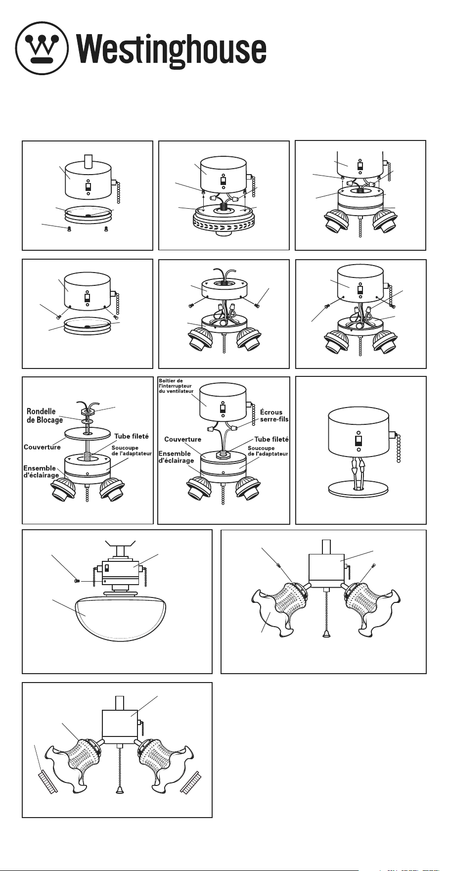
ENSEMBLE D’ÉCLAIRAGE POUR VENTILATEUR DE PLAFOND
INSTRUCTIONS D’INSTALLATION ET CONSIGNES DE SÉCURITÉ
Merci d'avoir sélectionné l'un de nos produits de qualité supérieure. Nous
consacrons un temps et un effort de travail particuliers pour garantir que ces
produits sont les meilleurs du marché.
Pour que cette installation soit réussie, veuillez lire ces instructions et bien
revoir les diagrammes avant de débuter. Suivre les instructions qui
correspondent à votre ensemble d'éclairage.
Les ensembles d’éclairage pour ventilateurs de plafond ne peuvent être utilisés
qu’avec des ventilateurs de plafond. Ils ne peuvent être installés comme
luminaires.
Attention – Risque de choc électrique. Avant de débuter l’installation, couper
l’alimentation électrique au disjoncteur ou enlever le fusible dans le boîtier
à fusibles. Le fait de mettre l’interrupteur du ventilateur sur Arrêt n’est pas
suffisant pour éviter les risques d’électrocution.
Reportez-vous aux instructions d'installation fournies avec votre
ventilateur. Assurez-vous que votre ventilateur a été correctement raccordé au
plafond pour pouvoir l'utiliser avec l'ensemble d'éclairage.
Tous les raccordements électriques doivent être effectués conformément aux
codes et règlements locaux ou aux codes électriques nationaux.
Si vous n’êtes pas familier avec l’installation de câbles électriques, consultez un
électricien qualifié.
NOTE : Les importantes consignes de sécurité et instructions de ce manuel ne
sauraient prévoir toutes les conditions et situations possibles.
TOUS LES ENSEMBLES D’ÉCLAIRAGE
À AMPOULE UNIQUE :
1-abat-jour (en verre ou autre)*
1-pièce d’ajustement avec douille
assemblée
1-sac de plastique contenant :
-vis de l’abat-jour
-chaînette
-rondelle de blocage
-écrou de vis
-connecteur de fil
ENSEMBLE D’ÉCLAIRAGE À
3 AMPOULES :
1-luminaire
3-ampoules avec abat-jour*
1- sac de plastique contenant :
-vis pour abat-jours ou bagues
pour douille
-chaînette
-rondelle de blocage
-écrou de vis
-connecteur de fil
ENSEMBLE D’ÉCLAIRAGE À
4 AMPOULES :
1-luminaire
4-ampoules avec abat-jour*
1-sac de plastique contenant :
-vis de l’abat-jour
-chaînette
-rondelle de blocage
-écrou de vis
-connecteur de fil
*CERTAINS ENSEMBLES D’ÉCLAIRAGE NE COMPRENNENT PAS LES
ABAT-JOUR (EN VERRE OU AUTRE).
PIÈCES
RENSEIGNEMENTS GÉNÉRAUX
Figure 5
Figure 1
Figure 4
Figure 2
Figure 3
Figure 6
Figure 9a
Boîtier de
l'interrupteur
du ventilateur
Couvercle
Bouchon
Vis
Boîtier de
l'interrupteur
du ventilateur
Logement
de
Clavette
Vis
Écrous
serre-fils
Ensemble
d'éclairage
de
ventilateur
Boîtier de
l'interrupteur
du ventilateur
Logement
de
Clavette
Vis
Écrous
serre-fils
Ensemble
d'éclairage
de
ventilateur
Soucoupe
de
L'adaptateur
Boîtier de
l'interrupteur
du ventilateur
Couvercle
Vis
Bouchon
Soucoupe
de
l'adaptateur
Ensemble
d'éclairage
de ventilateur
Vis
Boîtier de
l'interrupteur
du ventilateur
Vis
Écrous
serre-fils
Ensemble
d'éclairage
de
ventilateur
Câblage Canadien
Figure 8
Figure 7
L’ecrou
Hexagonal
ENSEMBLE D’ÉCLAIRAGE POUR VENTILATEUR DE PLAFOND
INSTRUCTIONS D’INSTALLATION ET CONSIGNES DE SÉCURITÉ
ENSEMBLE D’ÉCLAIRAGE POUR VENTILATEUR DE PLAFOND
INSTRUCTIONS D’INSTALLATION ET CONSIGNES DE SÉCURITÉ
Figure 10
Figure 11
Figure 9b
Vis
Abat-jour
Boîtier de
l'interrupteur
du ventilateur
Ampoule
Ensemble
d'éclairage
Vis
Abat-jour
Boîtier de
l'interrupteur
du ventilateur
Baffle
Figure 11
Abat-jour
Bagues
pour Douille
Boîtier de
l'interrupteur
du ventilateur
Si l’ensemble d’éclairage ne fonctionne pas, couper le courant et abaisser le chapeau
conique ou le boîtier décoratif du ventilateur pour vous assurer que le fil bleu est connecté
au fil noir de la résidence. Se reporter à la section sur les raccordements électriques du
manuel d’instruction du ventilateur de plafond.
DÉPANNAGE
1. Si vous souhaitez remplacer le plafonnier
de l'appareil d'éclairage, desserrez l'écrou
hexagonal et le fleuron pour le dégager. (Voir
figure 12.)
2. Lorsque vous réinstallez le plafonnier,
placez la rondelle éventail sur le tube
fileté, puis serrez l'écrou hexagonal. Passez
l'interrupteur par le trou latéral du plafonnier,
puis serrez avec le fleuron. (Voir figure 12.)
REMARQUE : Pour les adaptateurs au
fini blanc et nickel brossé, veuillez utiliser
la quincaillerie en nickel brossé; pour les
adaptateurs de bronze huilé, veuillez utiliser la
quincaillerie au fini laiton antique.
PROCÉDURES D'INSTALLATION POUR LE PLAFONNIER
Rondelle
Etoilee
Ecrou
Decoratif
Chapeau
Commutateur
Figure 12
L’ecrou
Hexagonal
Call 1-800-999-2226 or Fax 215-464-4115
In Pacific and Mountain Time Zones
Call 1-800-421-3433 or Fax 562-404-4352
, WESTINGHOUSE, and INNOVATION YOU CAN BE SURE OF
are trademarks of Westinghouse Electric Corporation.
Used under license by Westinghouse Lighting.
All rights reserved. Made in China
Westinghouse Lighting, Philadelphia, PA 19154-1029, U.S.A.
www.westinghouselighting.com
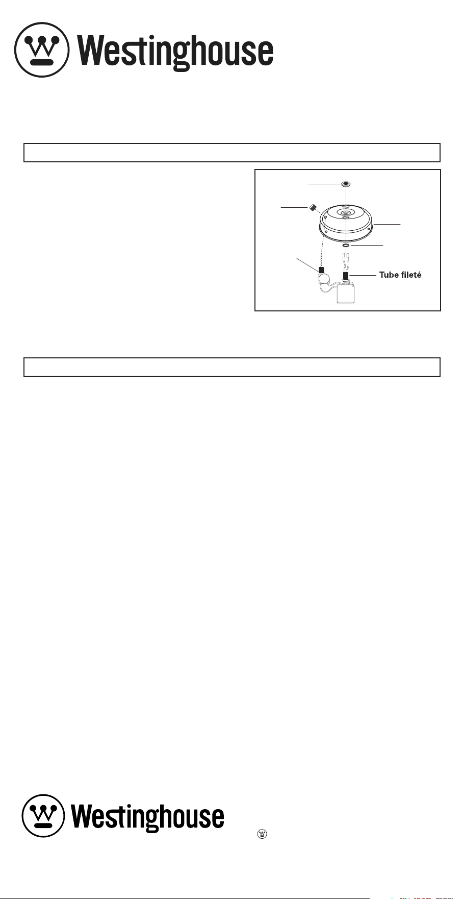
ENSEMBLE D’ÉCLAIRAGE POUR VENTILATEUR DE PLAFOND
INSTRUCTIONS D’INSTALLATION ET CONSIGNES DE SÉCURITÉ
Merci d'avoir sélectionné l'un de nos produits de qualité supérieure. Nous
consacrons un temps et un effort de travail particuliers pour garantir que ces
produits sont les meilleurs du marché.
Pour que cette installation soit réussie, veuillez lire ces instructions et bien
revoir les diagrammes avant de débuter. Suivre les instructions qui
correspondent à votre ensemble d'éclairage.
Les ensembles d’éclairage pour ventilateurs de plafond ne peuvent être utilisés
qu’avec des ventilateurs de plafond. Ils ne peuvent être installés comme
luminaires.
Attention – Risque de choc électrique. Avant de débuter l’installation, couper
l’alimentation électrique au disjoncteur ou enlever le fusible dans le boîtier
à fusibles. Le fait de mettre l’interrupteur du ventilateur sur Arrêt n’est pas
suffisant pour éviter les risques d’électrocution.
Reportez-vous aux instructions d'installation fournies avec votre
ventilateur. Assurez-vous que votre ventilateur a été correctement raccordé au
plafond pour pouvoir l'utiliser avec l'ensemble d'éclairage.
Tous les raccordements électriques doivent être effectués conformément aux
codes et règlements locaux ou aux codes électriques nationaux.
Si vous n’êtes pas familier avec l’installation de câbles électriques, consultez un
électricien qualifié.
NOTE : Les importantes consignes de sécurité et instructions de ce manuel ne
sauraient prévoir toutes les conditions et situations possibles.
TOUS LES ENSEMBLES D’ÉCLAIRAGE
À AMPOULE UNIQUE :
1-abat-jour (en verre ou autre)*
1-pièce d’ajustement avec douille
assemblée
1-sac de plastique contenant :
-vis de l’abat-jour
-chaînette
-rondelle de blocage
-écrou de vis
-connecteur de fil
ENSEMBLE D’ÉCLAIRAGE À
3 AMPOULES :
1-luminaire
3-ampoules avec abat-jour*
1- sac de plastique contenant :
-vis pour abat-jours ou bagues
pour douille
-chaînette
-rondelle de blocage
-écrou de vis
-connecteur de fil
ENSEMBLE D’ÉCLAIRAGE À
4 AMPOULES :
1-luminaire
4-ampoules avec abat-jour*
1-sac de plastique contenant :
-vis de l’abat-jour
-chaînette
-rondelle de blocage
-écrou de vis
-connecteur de fil
*CERTAINS ENSEMBLES D’ÉCLAIRAGE NE COMPRENNENT PAS LES
ABAT-JOUR (EN VERRE OU AUTRE).
PIÈCES
RENSEIGNEMENTS GÉNÉRAUX
Figure 5
Figure 1
Figure 4
Figure 2
Figure 3
Figure 6
Figure 9a
Boîtier de
l'interrupteur
du ventilateur
Couvercle
Bouchon
Vis
Boîtier de
l'interrupteur
du ventilateur
Logement
de
Clavette
Vis
Écrous
serre-fils
Ensemble
d'éclairage
de
ventilateur
Boîtier de
l'interrupteur
du ventilateur
Logement
de
Clavette
Vis
Écrous
serre-fils
Ensemble
d'éclairage
de
ventilateur
Soucoupe
de
L'adaptateur
Boîtier de
l'interrupteur
du ventilateur
Couvercle
Vis
Bouchon
Soucoupe
de
l'adaptateur
Ensemble
d'éclairage
de ventilateur
Vis
Boîtier de
l'interrupteur
du ventilateur
Vis
Écrous
serre-fils
Ensemble
d'éclairage
de
ventilateur
Câblage Canadien
Figure 8
Figure 7
L’ecrou
Hexagonal
ENSEMBLE D’ÉCLAIRAGE POUR VENTILATEUR DE PLAFOND
INSTRUCTIONS D’INSTALLATION ET CONSIGNES DE SÉCURITÉ
ENSEMBLE D’ÉCLAIRAGE POUR VENTILATEUR DE PLAFOND
INSTRUCTIONS D’INSTALLATION ET CONSIGNES DE SÉCURITÉ
Figure 10
Figure 11
Figure 9b
Vis
Abat-jour
Boîtier de
l'interrupteur
du ventilateur
Ampoule
Ensemble
d'éclairage
Vis
Abat-jour
Boîtier de
l'interrupteur
du ventilateur
Baffle
Figure 11
Abat-jour
Bagues
pour Douille
Boîtier de
l'interrupteur
du ventilateur
Si l’ensemble d’éclairage ne fonctionne pas, couper le courant et abaisser le chapeau
conique ou le boîtier décoratif du ventilateur pour vous assurer que le fil bleu est connecté
au fil noir de la résidence. Se reporter à la section sur les raccordements électriques du
manuel d’instruction du ventilateur de plafond.
DÉPANNAGE
1. Si vous souhaitez remplacer le plafonnier
de l'appareil d'éclairage, desserrez l'écrou
hexagonal et le fleuron pour le dégager. (Voir
figure 12.)
2. Lorsque vous réinstallez le plafonnier,
placez la rondelle éventail sur le tube
fileté, puis serrez l'écrou hexagonal. Passez
l'interrupteur par le trou latéral du plafonnier,
puis serrez avec le fleuron. (Voir figure 12.)
REMARQUE : Pour les adaptateurs au
fini blanc et nickel brossé, veuillez utiliser
la quincaillerie en nickel brossé; pour les
adaptateurs de bronze huilé, veuillez utiliser la
quincaillerie au fini laiton antique.
PROCÉDURES D'INSTALLATION POUR LE PLAFONNIER
Rondelle
Etoilee
Ecrou
Decoratif
Chapeau
Commutateur
Figure 12
L’ecrou
Hexagonal
Call 1-800-999-2226 or Fax 215-464-4115
In Pacific and Mountain Time Zones
Call 1-800-421-3433 or Fax 562-404-4352
, WESTINGHOUSE, and INNOVATION YOU CAN BE SURE OF
are trademarks of Westinghouse Electric Corporation.
Used under license by Westinghouse Lighting.
All rights reserved. Made in China
Westinghouse Lighting, Philadelphia, PA 19154-1029, U.S.A.
www.westinghouselighting.com
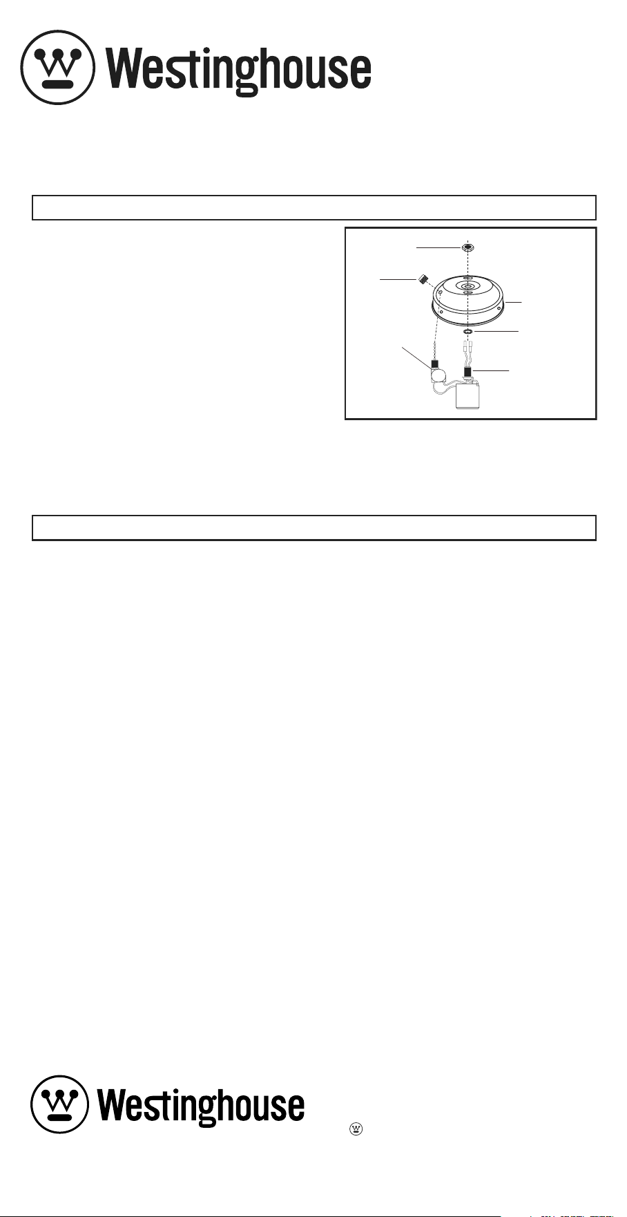
JUEGO DE LUCES PARA VENTILADOR DE TECHO
INSTRUCCIONES DE INSTALACIÓN Y SEGURIDAD
Gracias por seleccionar uno de nuestros productos de calidad superior.
Dedicamos tiempo y esfuerzo para asegurarnos de que sean los mejores
productos disponibles.
Para asegurarse de que la instalación sea correcta, asegúrese de leer estas
instrucciones y de consultar detenidamente los diagramas antes de comenzar.
Siga las instrucciones correspondientes para su juego de luces.
Los juegos de luces para ventiladores de techo deben usarse solamente con
ventiladores de techo. No deben instalarse como artefactos luminosos.
Advertencia – Riesgo de descarga eléctrica Antes de comenzar la instalación,
desconecte el suministro electrico, apagando el cortacircuito o quitando el
fusible. Apagando el suministro electrico usando el interruptor del ventilador
no es suficiente para evitar descargas eléctricas.
Lea las instrucciones de instalación incluidas con su ventilador.
Asegúrese de que el cableado de su ventilador haya sido correctamente
instalado en el techo para permitir el uso de un juego de luces.
Todas las conexiones eléctricas deben cumplir con los códigos y las
ordenanzas locales, y con los códigos eléctricos nacionales.
Si usted no tiene experiencia con los métodos para instalar cableado eléctrico,
solicite los servicios de un electricista certificado.
NOTA: Las instrucciones y las medidas preventivas incluidas en este manual no
tienen la intención de cubrir todas las condiciones y situaciones que pudieran
ocurrir.
TODOS LOS JUEGOS DE LUCES CON UNA
SOLA LÁMPARA
1 pieza de vidrio o pantalla*
1 encastre con portalámparas armado
1 bolsa plástica que incluye:
-tornillos para pantalla
-cadenilla de tiro
-arandela de presión
-tuerca rosca
-conector de cables
JUEGO DE LUCES CON
3 LÁMPARAS:
1 juego de luces
3 pantallas*
1 bolsa plástica que incluye:
-tornillos para pantalla o anillos para
portalámparas
-cadenilla de tiro
-arandela de presión
-tuerca rosca
-conector de cables
*ALGUNOS JUEGOS DE LUCES PODRÍAN NO INCLUIR PIEZAS DE VIDRIO
O PANTALLAS.
PIEZAS
CONSIDERACIONES GENERALES
Figura 5
Figura 1
Figura 4
Figura 2
Figura 3
Figura 6
Figura 9a
Cubierta del
Interruptor
del
Ventilador
Tapa
Enchufe
Tornillo
Cubierta del
interruptor
del
ventilador
Bocallave
Tornillo
Tuercas
para
cables
Juego
de Luces
para
Venti-
lador
Cubierta del
Interruptor
del
Ventilador
Bocallave
Tornillo
Tuercas
para
Cables
Juego
de Luces
para
Venti-
lador
Taza
Adaptadora
Cubierta del
Interruptor
del
Ventilador
Tapa
Tornillo
Enchufe
Taza
Adaptadora
Juego de
Luces
para
Venti-
lador
Tornilla
Cubierta del
Interruptor
del
Ventilador
Tornillo
Tuercas
para
Cables
Juego
de Luces
para
Venti-
lador
Cableado Canadiense
Figure 7
Figure 8
Tuerca
Hexagonal
Arandela de
Presión
Tapa
Tapa
Juego
de Luces
para
Venti-
lador
Juego
de Luces
para
Venti-
lador
Taza
Adaptadora
Taza
Adaptadora
Tubo
Roscado
Cubierta
del
Interruptor
del
Ventilador
Tuercas
Para
Cables
Tubo
Roscado
JUEGO DE LUCES PARA VENTILADOR DE TECHO
INSTRUCCIONES DE INSTALACIÓN Y SEGURIDAD
JUEGO DE LUCES PARA VENTILADOR DE TECHO
INSTRUCCIONES DE INSTALACIÓN Y SEGURIDAD
Figura 10
Figura 11
Figura 9b
Tornillo
Pantalla
Cubierta
del Interruptor
del Ventilador
Lámpara
Juego de Luces
Tornillo
Pantalla
Cubierta del
Interruptor
del Ventilador
Bafle
Figura 11
Pantalla
Anillos para
Portalámparas
Cubierta del
Interruptor
del Ventilador
Si el juego de luces no funciona, apague el suministro eléctrico y baje el dosel o el alo-
jamiento decorativo del ventilador de techo para asegurarse de que el cable azul esté
conectado al cable negro de la casa. Consulte la sección de electricidad en el manual de
instrucciones del ventilador de techo.
GUÍA PARA SOLUCIONAR PROBLEMAS
1. Si desea reemplazar el ajustador del juego
de luces para ventilador, afloje la tuerca
hexagonal y el cojinete para liberar el
ajustador. (Vea la figura 12.)
2. Durante la reinstalación, coloque el
ajustador, la arandela en estrella sobre
el tubo roscado, luego ajuste con la tuerca
hexagonal. Pase el interruptor a través del
agujero lateral del ajustador y luego ajuste
con el cojinete. (Vea la figura 12.)
NOTA: Para los ajustador con acabado
color blanco y níquel, use la tornillería con
acabado color níquel; para el ajustador con
acabado color bronce con pátina al aceite,
use la tornillería con acabado latón estilo
antiguo.
INSTALACIÓN DE AJUSTADOR DE REEMPLAZO
Arandela
en estrella
Floron
Ajustador
Interruptor
Figure 12
Tuerca
Hexagonal
Tubo
Roscado
Call 1-800-999-2226 or Fax 215-464-4115
In Pacific and Mountain Time Zones
Call 1-800-421-3433 or Fax 562-404-4352
, WESTINGHOUSE, and INNOVATION YOU CAN BE SURE OF
are trademarks of Westinghouse Electric Corporation.
Used under license by Westinghouse Lighting.
All rights reserved. Made in China
Westinghouse Lighting, Philadelphia, PA 19154-1029, U.S.A.
www.westinghouselighting.com