Loading ...
Loading ...
Loading ...
ASSE LY
HOW TO SET UP YOUR SNOW
THROWER
O
Your snow thrower is equipped with height adjust
skids (See Fig 2) on the outside of the auger
housing To adjust the skid height for different
conditions, see To Adjust Skid Height paragraph on
page 18
TO INSTALL THE UPPER HANDLE
AND CRANK ASSEMBLY
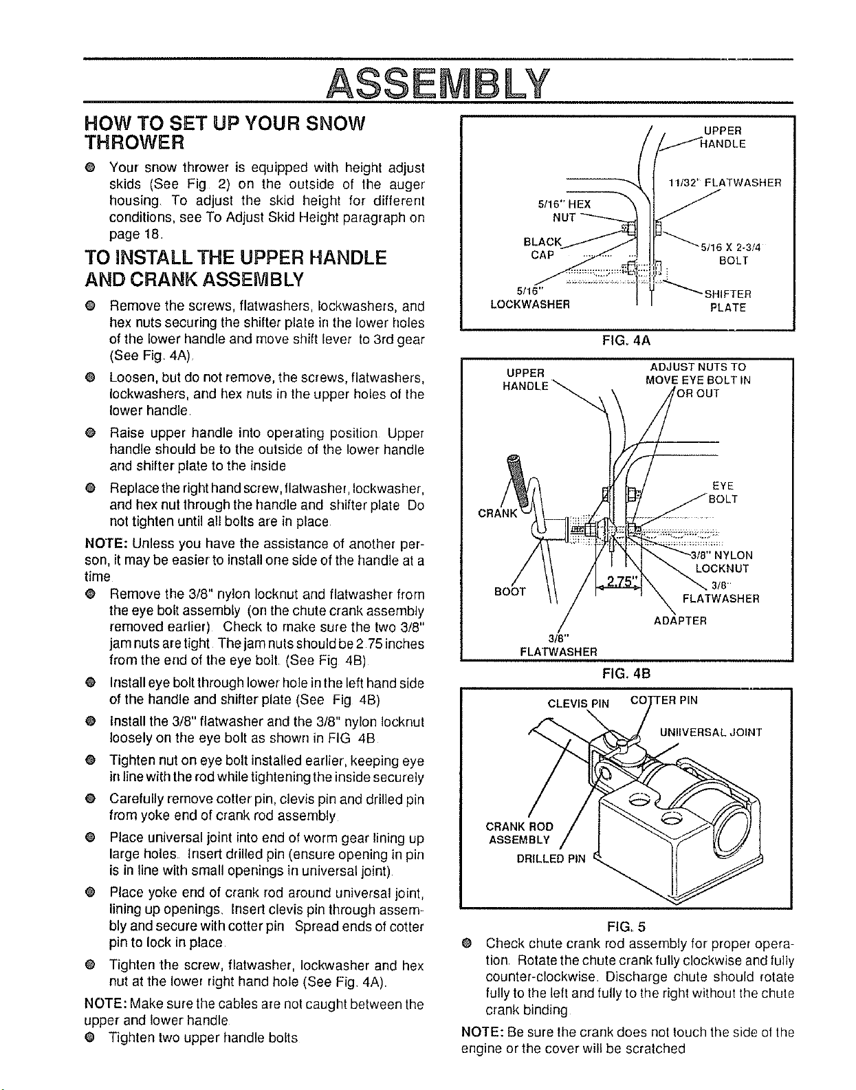
@ Remove the screws, fiatwashers, Iockwashers, and
hex nuts securing the shifter plate in the lower holes
of the lower handle and move shift lever to 3rd gear
(See Fig 4A)
@ Loosen, but do not remove, the screws, flatwashers,
Iockwashers, and hex nuts in the upper holes of the
lower handle
o
o
Raise upper handle into operating position Upper
handle should be to the outside of the lower handle
arrd shitter plate to the inside
Replace the right hand screw, flatwasher, Iockwasher,
and hex nut through the handle arrd shifter plate Do
not tighten until all bolts are in place
NOTE: Unless you have the assistance of another per-
son, it may be easier to install one side of the handle at a
time
@ Remove the 3/8" nylon Iocknut and flatwasher from
the eye bolt assembly (on the chute crank assembly
removed earlier) Check to make sure the two 3/8"
jam nuts are tight The jam nuts should be 2 75 inches
from the end of the eye bolt (See Fig 4B)
O Install eye bolt through lower hole inthe left hand side
of the handle and shifter plate (See Fig 4B)
O install the 3/8" fiatwasher and the 3/8" nylon Iocknut
loosely on the eye bolt as shown in FIG 4B
O Tighten nut on eye bolt installed earlier, keeping eye
in line with the rod while tightening the inside securely
e Carefully remove cotter pin, clevis pin and drilled pin
from yoke end of crank rod assembly
O Place universal joint into end of worm gear lining up
large holes Insert drilled pin (ensure opening in pin
is in line with small openings in universal joint)
o
Place yoke end of crank rod around universal joint,
lining up openings, Insert clevis pin through assem-
bly and secure with cotter pin Spread ends of cotter
pin to lock in place
O Tighten the screw, flatwasher, Iockwasher arrd hex
nut at the lower right hand hole (See Fig 4A)
NOTE: Make sure the cables are not caught between the
upper and lower handle
O Tighten two upper handle bolts
UPPER
5/16" HEX
11/32' FLATWASHEB
BLACK 16 X 2-3/4
CAP BOLT
5/16" 'SHIFTER
LOCKWASHER PLATE
FIGo 4A
UPPER ADJUST NUTS TO
HANDLE _ MOVE EYE BOLT IN
"'4
OUT
EYE
CLON
LOCKNUT
3/8"
BOOT
FLATWASHER
ADAPTER
3/8"
FLATWASHER
FIG. 4B
i
CLEVIS PIN TER PIN
UNllVERSAL JOINT
CRANK ROD
ASSEMBLY
DRILLED PIN
FIG. 5
O Check chute crank rod assembly for proper opera-
tion Rotate the chute crank fully clockwise and fully
counter-clockwise Discharge chute should rotate
fully to the left and fully to the right without tile chute
crank binding
NOTE: Be sure the crank does not touch the side of the
engine orthe cover will be scratched
Loading ...
Loading ...
Loading ...