Loading ...
Loading ...
Loading ...
ASSEMBLY
TOOLS REQUIRED FOR ASSEMBLY
I - Knife (to cut carton and plastic ties)
2 - 1/2 inch wrenches (or adjustable wrenches)
2 - 9/16 inch wrenches (or adjustable wrenches)
2 - 3/4 inch wrenches (or adjustable wrenches)
1 - Pliers (to spread cotter pin)
1- Screwdriver
1 - Measuring tape or ruler
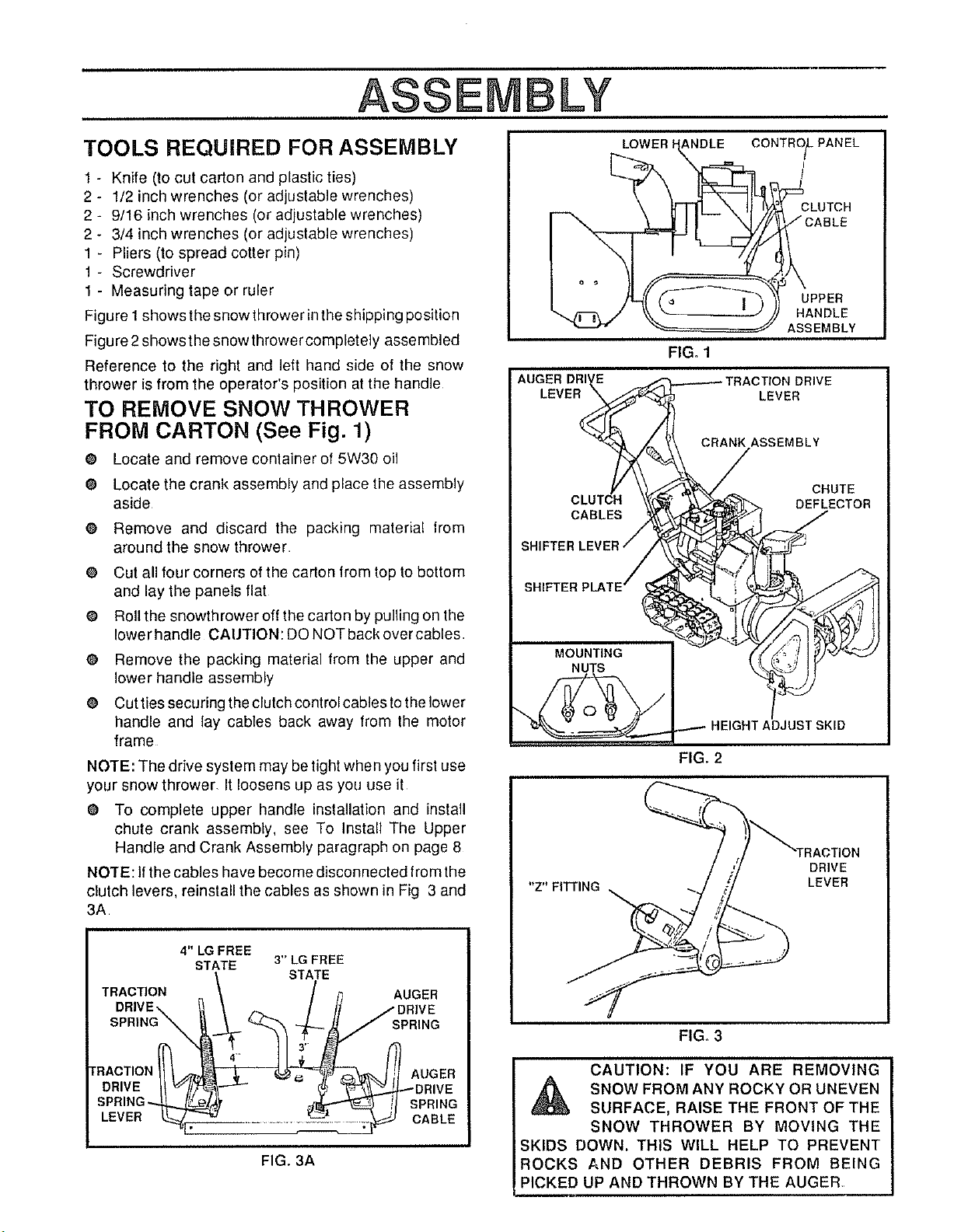
Figure I shows the snow thrower in the shipping position
Figure 2 shows the snowthrower completely assembled
Reference to the right and left hand side of the snow
thrower is from the operator's position at the handle
TO REMOVE SNOW THROWER
FROM CARTON (See Fig. 1)
@ Locate and remove container of 5W30 oil
e Locate the crank assembly and place the assembly
aside
O Remove and discard the packing material lrom
around the snow thrower
O Cut all four corners of the carton from top to bottom
and lay the panels flat
@ Roll the snowthrower off the carton by pulling on the
lower handle CAtJTION: DO NOT back over cables
@ Remove the packing material from the upper and
lower handle assembly
@ Cut ties securing the clutch control cables to the lower
handle and lay cables back away Irom the motor
frame
NOTE: The drive system may be tight when you first use
your snow thrower, It loosens up as you use it
@ To complete upper handle installation and install
chute crank assembly, see To Install The Upper
Handle and Crank Assembly paragraph on page 8
NOTE: If the cables have become disconnected from the
clutch levers, reinstall the cables as shown in Fig 3 and
3A
4" LG FREE
STATE 3" LG FREE
/ STATE
TRACTION \ / ,'_ AUGER
DRIVE\ _ _ / // /DRIVE
sP°,NO\ ;pR,NO
DR,VE --" / y_j DR,VE
SPR,N -. t ;P,,NG
LEVE. CASLE
FIG, 3A
LOWER ANDLE
CONTRO_PANEL
i
t
CLUTCH
UPPER
HANDLE
ASSEMBLY
FIG. 1
LEVER
CRANK ASSEMBLY
FIG, 2
"Z" FITI'ING
DRIVE
LEVER
FIG. 3
CAUTION: IF YOU ARE REMOVING
SNOW FROM ANY ROCKY OR UNEVEN
SURFACE, RAISE THE FRONT OF THE
SNOW THROWER BY MOVING THE
SKIDS DOWN. THIS WILL HELP TO PREVENT
ROCKS AND OTHER DEBRIS FROM BEING
PICKED UP AND THROWN BY THE AUGER
Loading ...
Loading ...
Loading ...