CRRFTSMRW
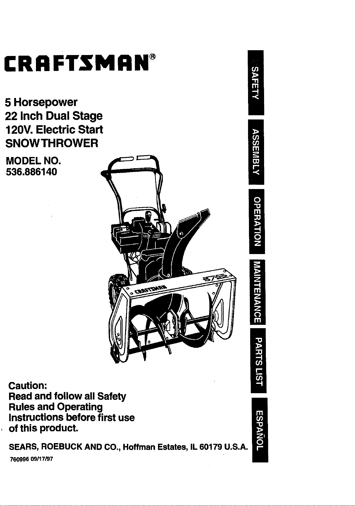
5 Horsepower
22 Inch Dual Stage
120V. Electric Start
SNOWTHROWER
MODEL NO.
536.886140
Caution:
Read and follow all Safety
Rules and Operating
Instructions before first use
, of this product.
SEARS, ROEBUCK AND CO., Hoffman Estates, IL 60179 U.S.A.
760996 09/17/97
Table of Contents 2 Service and Adjustments 17-21
Warranty 2 Storage 22
Safety Rules 2-4 Troubleshooting 23
Contents of Shipping Carton 4-5 Repair Parts 24-32
Assembly 5-8 Engine Repair Parts 33-37
Operation 8-14 Spanish(EspaSol) 38-63
Maintenance 14-16 Parts Ordering/Service Back Cover
LIMITED TWO-YEAR WARRANTY ON CRAFTSMAN SNOW THROWER
For two years from the date of purchase, when this Craftsman Snow Thrower is maintained,
lubricated, and tuned up according to the operating and maintenance instructions in the
owner's manual, Craftsman will repair, free of charge, any defect in material or workmanship.
If this Craftsman Snow Thrower is used for commercial or rental purposes, this warranty
applies for only 90 days from the date of purchase..
This warranty does not cover the following:
• Items which become wom during normal use, such as spark plugs, drive belts and
shear pins.
• Repairs necessary because of operator abuse or negligence, including bent crank
shafts and the failure to maintain the equipment according to the instructions con-
tained in the owner's manual.
WARRANTY SERVICE IS AVAILABLE BY RETURNING THE CRAFTSMAN SNOW
THROWER TO THE NEAREST CRAFTSMAN SERVICE CENTER/DEPARTMENT IN THE
UNITED STATES. THIS WARRANTY APPLIES ONLY WHILE THIS PRODUCT IS IN USE
IN THE UNITED STATES.
This warranty gives you specific legal rights, and you may also have other rights which may
vary from state to state.
Sears, Roebuck and Co., D817WA, Hoffman Estates, IL 60179
/_ Look for this symbol to point out Important safety precauUons. It means--
ATTENTION!I! Become alertll! Your safety is involved,
Z_ CAUTION: Always disconnect spark
plug wire and place wire where it cannot
contact spark plug to prevent accidental
starting when setting-up, transporting,
adjusting or making repairs.
IMPORTANT: Safety standards require
operator presence controls to minimize the
risk of injury. Your snow thrower is
equipped with such controls. Do not attempt
to defeat the function of the operator
presence control under any circumstances.
California Proposition 65
WARNING:Tho
TRAINING
1. Read the operator's manual carefully.
Be thoroughly familiar with the controls
and the proper use of the snow throws
Know how to stop the snow thrower ar
disengage the controls quickly.
2. Never allow children to operate the sr
thrower and keep them away while it
operating. Never allow adults to oper
the snow thrower without proper inst_
tion. Do not carry passengers.
3. Keep the area of operation clear of f
persons, particularly small children
pets. °
4. Exercise caution to avoid slipping c
falling, especially when operating I,
reverse.
PREPARATION
.
Thoroughly inspect the area whw
snow thrower is to be used an_
all doormats, sleds, boards, wit
other foreign objects.
,
3.
.
Disengage all clutches before starting
the engine (motor).
Do not operate the snow thrower
without wearing adequate winter outer
garments.Wear footwear that will
improve footing on slippery surfaces.
Handle fuel with care; it is highly
flammable.
(a) Use an approved fuel container.
(b) Never remove fuel tank cap or add
fuel to a running engine or hot
engine.
(c) Fill fuel tank outdoors with
extreme care. Never fill fuel tank
indoors.
(d) Replace fuel tank cap securely
and wipe up spilled fuel.
(e) Never store fuel or snow thrower
with fuel in the tank inside of a
building where fumes may reach
an open flame or spark.
(f) Check fuel supply before each
use, allowing space for expansion
as the heat of the engine (motor)
and/or sun can cause fuel to
expand.
5. Use extension cords and receptacles
as specified by the manufacturer for all
snow throwers with electric drive
motors or electric starting motors.
6. Adjust the snow thrower height to clear
gravel or crushed reck surfaces.
7. Never attempt to make any adjust-
ments while the engine (motor) is
running (except when specifically
recommended by the manufacturer).
8. Let engine (motor) and snow thrower
adjust to outdoor temperatures before
starting to clear snow.
9. Always wear safety glasses or eye
shields during operation or while
performing an adjustment or repair to
protect eyes from foreign objects that
may be thrown from the snow thrower.
OPERATION
1. Do not operate this machine if you are
taking drugs or other medication which
can cause drowsiness or affect your
ability to operate this machine.
2. Do not use this machine if you are
mentally or physically unable to
operate this machine safely.
3. Do not put hands or feet near or under
rotating parts. Keep c!ear of the
discharge opening at all times.
4. Exercise extreme caution when oper-
ating on or crossing gravel drives,
walks, or roads. Stay alert for hidden
hazards or traffic.
5. After striking a foreign object, stop the
engine (motor), remove the wire from
the spark plug, disconnect the cord on
electric motors, thoroughly inspect the
snow thrower for any damage, and
repair the damage before
operating the snow thrower.
6. Ifthe snow thrower should start to
vibrate abnormally, stop the (motor)
and check immediately for the cause.
Vibration is generally a warning of
trouble.
7. Stop the engine (motor) whenever you
leave the operating position, before
unclogging the auger/impeller housing
or discharge guide, and when making
any repairs, adjustments, or inspec-
tions.
8. When cleaning, repairing, or inspecting,
make certain the auger/impeller and all
moving parts have stopped. Disconnect
the spark plug wire and keep the wire
away from the plug to prevent acciden-
tal starting.
9. Take all possible precautions when
leaving the snow thrower unattended.
Disengage the auger/impeller, stop
engine, and remove key.
10. Do not run the engine indoors, except
when startingthe engine and for
transporting the snow thrower in or out
of the building. Open the outside doors;
exhaust fumes are dangerous (contain-
ing CARBON MONOXIDE, an ODOR-
LESS and DEADLY GAS).
11. Do not clear snow across the face of
slopes. Exercise caution when changing
direction on slopes. Do not attempt to
clear steep slopes.
12. Never operate the snow thrower without
proper guards, plates or other safety
protective devices in place.
13. Never operate the snow thrower near
glass enclosures, automobiles, window
wells, drop-offs, and the like without
proper adjustment of the snow
discharge angle. Keep children and
pets away.
14. Do not overload the machine capacity
by attempting to clear snow at too fast
a rate.
15. Never operate the snow thrower at high
transport speeds on slippery surfaces.
Look behind and use care when
backing.
16. Never direct discharge at bystanders or
allow anyone infront of the snow
thrower.
17. Disengagepowertotheauger/impeller
whensnowthroweristransportedor
not inuse.
18, Useonlyattachmentsandaccessories
approvedbythemanufacturerofthe
snowthrower(suchastirechains,
electricstartkits,etc.).
19. Neveroperatethesnowthrower
withoutgoodvisibilityorlight.Always
be sureofyourfooting,andkeepa
firm holdonthehandles.Walk;never
run.
MAINTENANCE ANDSTORAGE
1. Check shear bolts and other bolts
frequently for proper tightness to be
sure the snow thrower is in safe
working condition.
2. Never store the snow thrower with fuel
in the fuel tank inside a building where
ignition sources are present such as
hot water and space heaters, clothes
dryers, and the like. Allow the engine to
cool before storing in any enclosure.
3. Always refer to operator's manual
instructions for important details if the
snow thrower is to be stored for an
extended period.
4. Maintain or replace safety and instruc
tion labels, as necessary.
5. Run the snow thrower a few minutes
after throwing snow to prevent freeze-
up of the auger/impeller.
A
WARNING: This snow thrower is for
use on sidewalks, driveways and other
ground level surfaces.
Caution should be exercised while using on
steep sloping surfaces. DO NOT USE
SNOW THROWER ON SURFACES
ABOVE GROUND LEVEL such as roofs of
residences, garages, porches or other such
structures or buildings.
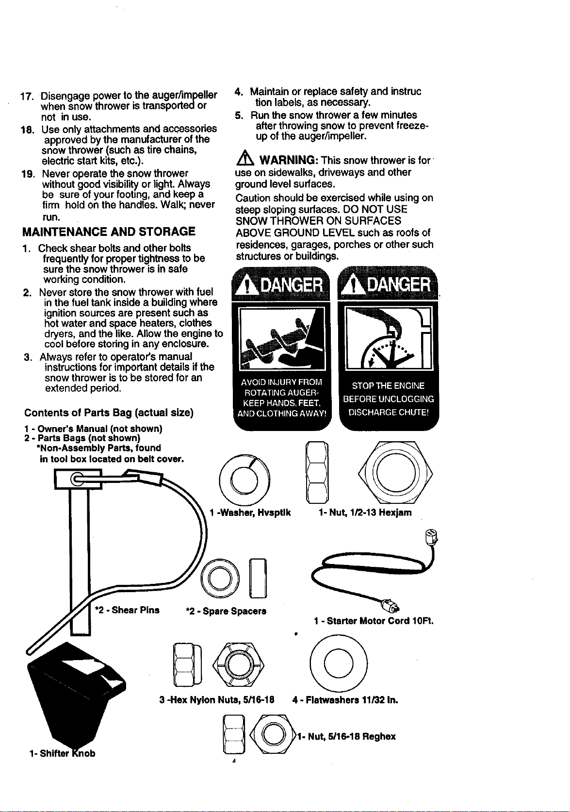
Contents of Parts Bag (actual size)
1 - Owner's Manual (not shown)
2 - Parts Bags (not shown)
*Non-Assembly Parts, found
in tool box located on belt cover.
©
1 -Washer, Hvsptlk 1- Nut, 1/2-13 Hexjam
1- Shifter I
*2 - Shear Pins
*2 - Spare Spacers
3 -Hex Nylon Nuts, 5/16-18
1 - Starter Motor Cord lOFt.
4 - Flatwaahers 11/32 In.
_1- Nut, 5/16-18 Reghex
A
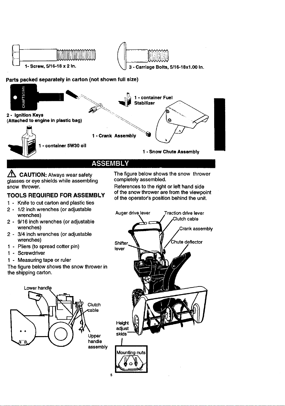
1- Screw, 5/16-18 x 2 In.
_ 5116-18x1.00 In.
Parts packed separately in carton (not shown full size)
2 - Ignition Keys
(Attached to engine in plastic bag)
1 - container 5W30 oil
1 - container Fuel
Stabilizer
1 - Crank Assembly
1 - Snow Chute Assembly
CAUTION: Always wear safety
glasses or eye shields while assembling
snow thrower.
TOOLS REQUIRED FOR ASSEMBLY
1 - Knife to cut carton and plastic ties
2 - 1/2 inch wrenches (or adjustable
wrenches)
2 - 9/16 inch wrenches (or adjustable
wrenches)
2 - 3/4 inch wrenches (or adjustable
wrenches)
t - Pliers (to spread cotter pin)
1 - Screwddver
1 - Measuring tape or ruler
The figure below shows the snow thrower in
the shipping carton.
The figure below shows the snow thrower
completely assembled.
References to the right or left hand side
of the snow thrower are from the viewpoint
of the operator's position behind the unit.
Auger drive lever
cable
ly
lever
Lower hand!
=_ Clutch
able
e
assembly
Height
adjust
skids
/
5

TO REMOVE SNOW THROWER
FROM CARTON
• Locate and remove container of 5W30 oil.
• Locate all parts packed separately and
remove from the carton.
NOTE: Place fuel stabilizer in a safe place
until needed for storage.
• Remove and discard the packing material
from around the snow thrower.
• Cut all four comers of the carton from top
to bottom and lay the panels flat.
• Roll the snow thrower off the carton by
pulling on the lower handle. CAUTION:
DO NOT back over cables.
• Remove the packing material from
handle assembly and plastic protector on
top of auger housing.
• Cut ties securing the clutch control cables
to the lower handle and lay cables back
away from the motor frame.
TO INSTALL THE UPPER HANDLE
AND CRANK ASSEMBLY
• Cut tie holding shift rod to lower handle
and move shifter to the first gear.
• Loosen, but do not remove the screws,
flatwashers, Iockweshers and hex nuts in
the upper holes of the lower handle. See
figure below.
Upper handle
Loosen do not
remove
11/32_ Ratwasher
5/16" hex Nut .-,
5/16 X 2"
5/16"
• Raise upper handle into operating posi-
tion. Upper handle should be to the
outside of the lower handle.
NOTE: Make sure the cables are not caught
between the upper and lower handle.
NOTE: Ifthe cables have become discon-
nected from the clutch levers, reinstall the
cables as shown in figure below.
"Z' fitting
NOTE: Position cable through slots on
shifter plate.
• Install hardware supplied in the parts bag
(Screw, flatwasher, Iockwasher, and hex
nut) into middle hole on right hand side of
handles. Do not tighten until all bolts are
in place.
• Locate crank assembly removed earlier
and remove the 3/8" nylon Iocknut and
flatwasher from the eye bolt assembly.
See figure below.
• Reinstall flatwasher and adapter. Install
eye bolt through lower hole in the left
hand side of the handle. See figure be-
low.
• Install the 3/8" flatwasher and the 3/8" ny-
lon lock,nut on the eye bolt as shown in
figure below.
3/8" nylon
Iocknut
e Bolt
Ratwssher
Carefully remove cotter pin, clevis pin
and universal joint pin from yoke end of
crank rod assembly as shown in next fig-
ure.
• Place universal joint into end of worm
gear lining up large holes. Insert universal
joint pin (ensure opening in pin is in line
with small openings in universal joint).
• Place yoke end of crank rod around uni-
versal joint, lining up openings. Insert
clevis pin through assembly and secure
with cotter pin. Spread ends of cotter pin
to lock in,place. See next figure.
• Tighten nut on eye bolt, keeping eye in
line with the rod while tightening the in-
side securely.
• Tighten all handle bolts.
Crank Rod
Assembly
joint
pin
Universaljoint
Bracket
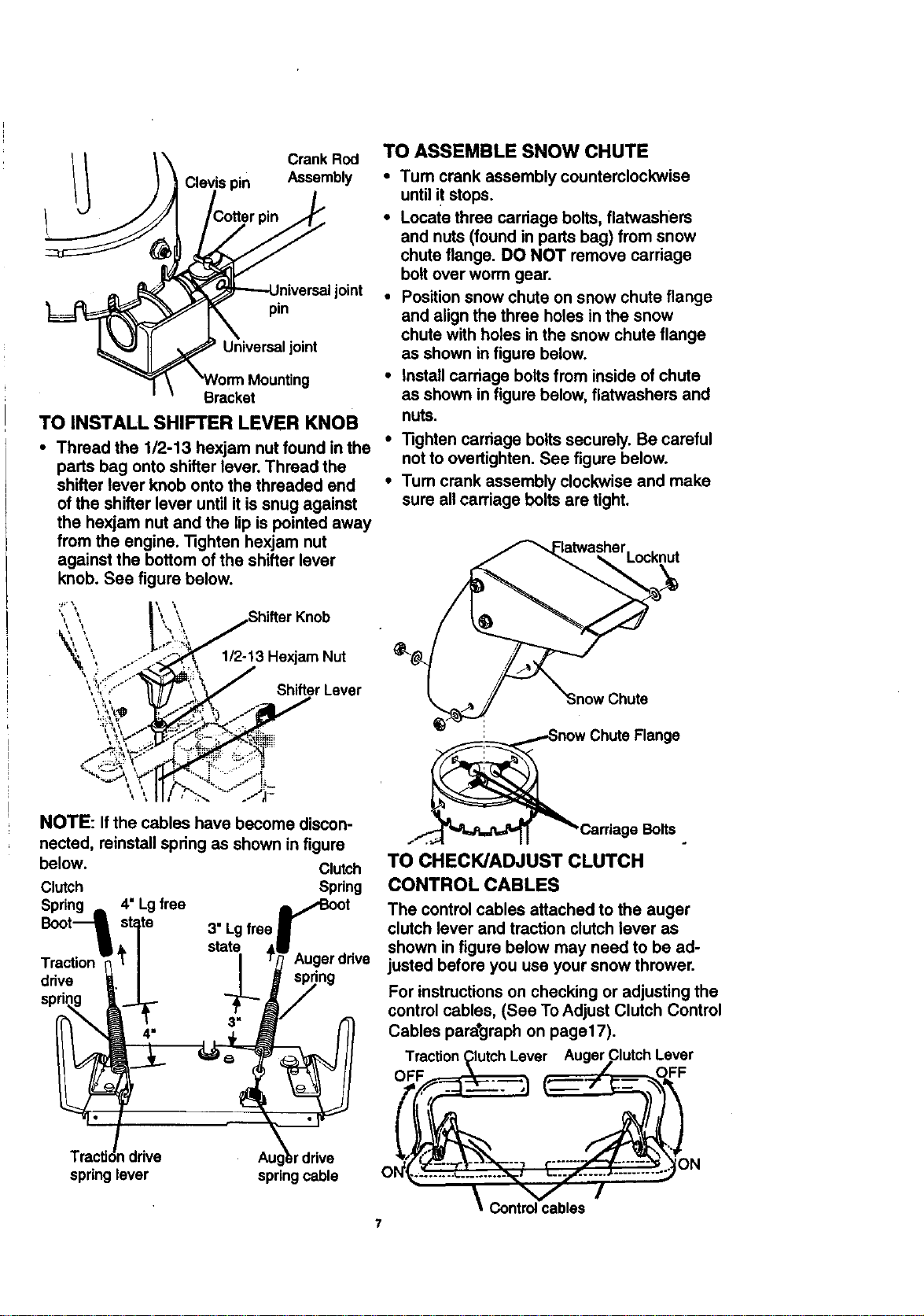
TO INSTALL SHIFTER LEVER KNOB
• Thread the 1/2-13 hexjam nut found in the
parts bag onto shifter lever. Thread the
shifter lever knob onto the threaded end
of the shifter lever until it is snug against
the hexjam nut and the lip is pointed away
from the engine. Tighten hexjam nut
against the bottom of the shifter lever
knob. See figure below.
TO ASSEMBLE SNOW CHUTE
•Tum crank assembly counterclockwise
until it stops.
• Locate three carriage bolts, flatwashers
and nuts (found in parts bag) from snow
chute flange. DO NOT remove carriage
bolt over worm gear.
• Position snow chute on snow chute flange
and align the three holes in the snow
chute with holes in the snow chute flange
as shown in figure below.
• install carriage bolts from inside of chute
as shown in figure below, flatwashers and
nuts.
• Tighten carriage bolts securely. Be careful
not to overtighten. See figure below.
•Tum crank assembly clockwise and make
sure all carriage bolts are tight.
Flange
7
NOTE: If the cables have become discon- Bolts
nected, reinstall spring as shown in figure
below. Clutch TO CHECK/ADJUST CLUTCH
Clutch Spring CONTROL CABLES
Spring ,,, 4"Lg free _IBoot The control cables attached to the auger
Boot1 state 3" Lgfree J clutch lever and traction clutch lever as
_ / state ,11 _ . shown in figure below may need to be ad-
Traction _'[ | I T_ Augerdnve justed before you use your snow thrower.
.va I / _J s_ng
spring " For instructions on checking or adjusting the
control cables, (See To Adjust Clutch Control
Cables para*graph on paget7).
Traction Clutch Lever Auger Clutch Lever
TracUdndrive Augkr drive "N_.......;..:.........,_ ...... )N
springlever springcable O .......... ._÷..... v_ _ .... /" .......... ""
\
Controlcables
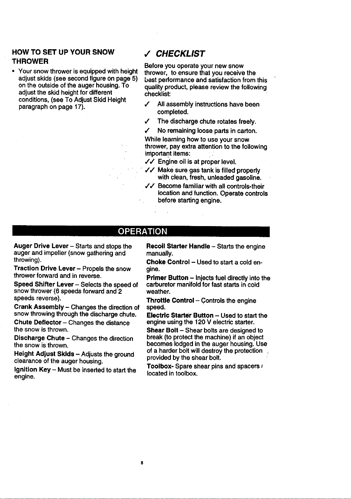
HOW TO SET UP YOUR SNOW
THROWER
• Your snow thrower is equipped with height
adjust skids (see second figure on page 5)
on the outside of the auger housing. To
adjust the skid height for different
conditions, (see To Adjust Skid Height
paragraph on page 17).
,/ CHECKLIST
Before you operate your new snow
thrower, toensure that you receive the
best performance and satisfaction from this
quality product, please review the following
checklist:
,/ All assembly instructions have been
completed.
,/ The discharge chute rotates freely.
/ No remaining loose parts in carton.
While learning how to use your snow
thrower, pay extra attention to the following
important items: i
,// Engine oil is at proper level.
,/,/ Make sure gas tank is filled properly
with clean, fresh, unleaded gasoline.
,/,/ Become familiar with all controls-their
location and function. Operate controls
before starting engine.
Auger Drive Lever - Starts and stops the
auger and impeller (snow gathering and
throwing).
Traction Drive Lever - Propels the snow
thrower forward and in reverse.
Speed Shifter Lever - Selects the speed of
snow thrower (6 speeds forward and 2
speeds reverse).
Crank Assembly - Changes the direction of
snow throwing through the discharge chute.
Chute Deflector - Changes the distance
the snow is thrown.
Discharge Chute - Changes the direction
the snow is thrown.
Height Adjust Skids - Adjusts the ground
clearance of the auger housing.
Ignition Key - Must be inserted to start the
engine.
Recoil Starter Handle - Starts the engine
manually.
Choke Control - Used to start a cold en-
gine.
Primer Button - Injects fuel directly into the
carburetor manifold for fast starts in cold
weather.
Throttle Control - Controls the engine
speed.
Electric Starter Button - Used to startthe
engine using the 120 V electric starter.
Shear Bolt - Shear bolts are designed to
break (to protect the machine) if an object
becomes lodged in the auger housing. Use
of a harder bolt will destroy the protection
provided by the shear bolt.
Toolbox- Spare shear pins and spacers 0
located in toolbox.
8
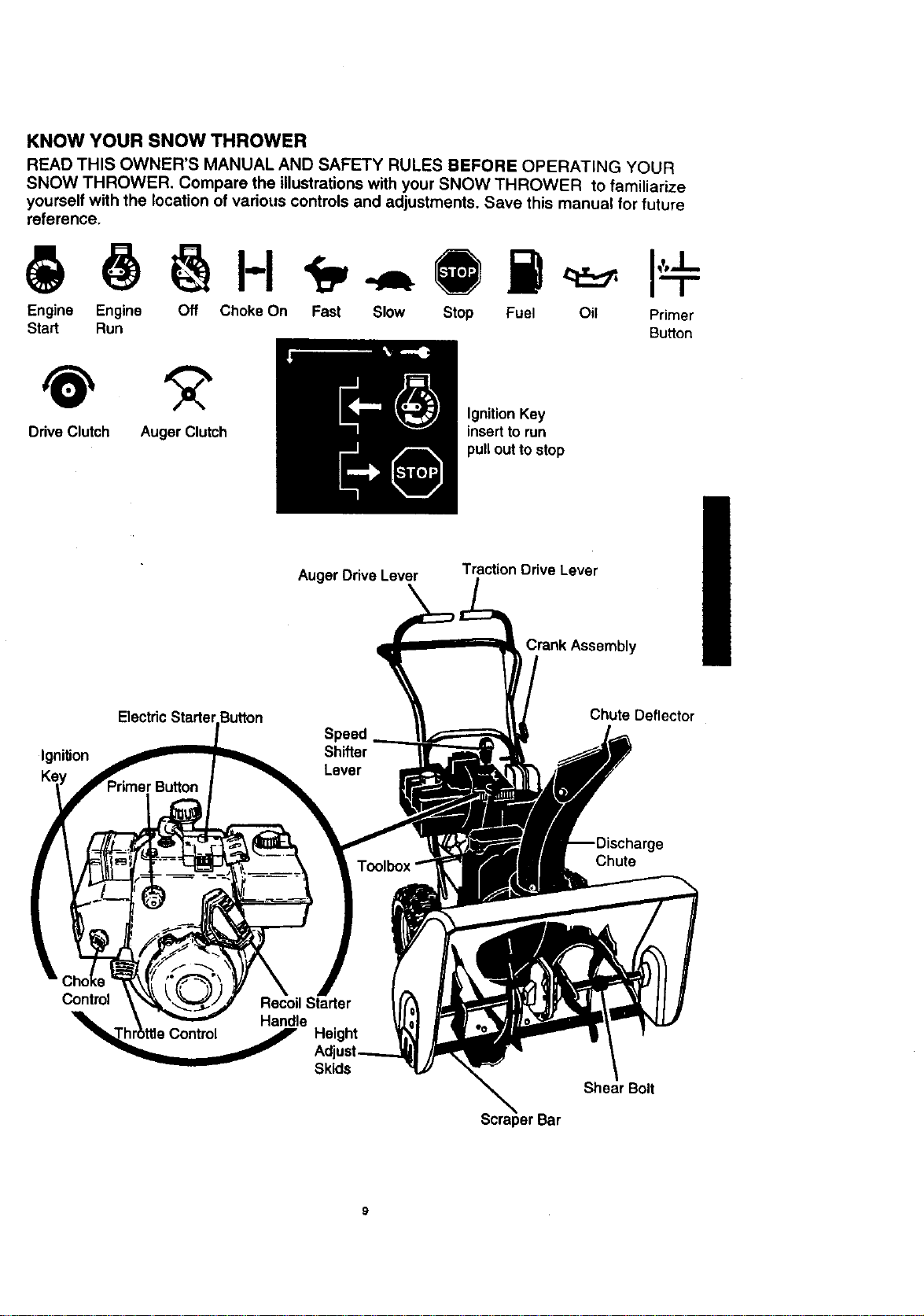
KNOW YOUR SNOW THROWER
READ THIS OWNER'S MANUAL AND SAFETY RULES BEFORE OPERATING YOUR
SNOW THROWER. Compare the illustrations with your SNOW THROWER to familiarize
yourself with the location of various controls and adjustments. Save this manual for future
reference.
Engine Engine Off Choke On Fast Slow Stop Fuel Oil Primer
Start Run Button
Drive Clutch Auger Clutch
Ignition Key
insert to run
pull out to stop
Auger Drive Lever Traction Drive Lever
Crank Assembly
IgniUon
Speed
Shifter
Lever
Chute Deflector
Chute
Control
Skids
Shear Bolt
The operation of any snow thrower can re-
sult in foreign objects being thrown into the
eyes, which can result in severe eye dam-
age. Always wear safety glasses or eye
shields while operating the snow thrower.
We recommend standard safety glasses or
a wide vision safety mask for over your
glasses, available at Craftsman Retail
Stores or Service Centers.
L_ CAUTION: Read owner's manual
before operating machine. Never direct
discharge toward bystanders. Release the
auger control bar and stop the engine
before unclogging discharge chute or auger
housing and before leaving the machine,
HOWTO USEYOUR SNOW
THROWER
TO STOP YOUR SNOW THROWER
• To stop throwing snow, release the auger
drive lever (see last figure on this page).
• To stop the wheels, release the traction
drive lever (see last figure on this page).
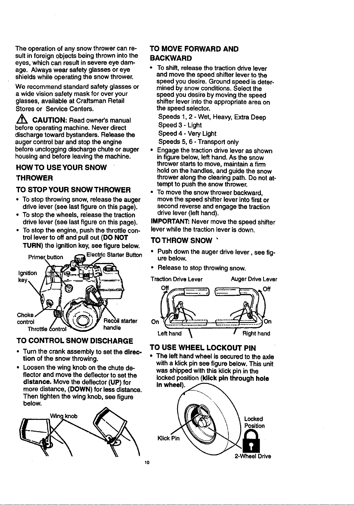
• To stop the engine, push the throttle con-
trol lever to off and pull out (DO NOT
TURN) the ignition kay, see figure below.
button c Starter Button
Ignition
TO MOVE FORWARD AND
BACKWARD
• To shift, release the traction drive lever
and move the speed shifter lever to the
speed you desire. Ground speed is deter-
mined by snow conditions. Select the
speed you desil'e by moving the speed
shifter lever into the appropriate area on
the speed selector.
Speeds 1,2 - Wet, Heavy, Extra Deep
Speed 3 +Light
Speed 4 - Very Light
Speeds 5, 6 - Transport only
• Engage the traction drive lever as shown
in figure below, left hand. As the snow
thrower starts to move, maintain a firm
hold on the handles, and guide the snow
thrower along the clearing path. Do not at-
tempt to push the snow thrower.
• To move the snow thrower backward,
move the speed shifter lever into first or
second reverse and engage the traction
drive lever (left hand).
IMPORTANT: Never move the speed shifter
lever while the traction lever is down.
TOTHROW SNOW '
• Push down the auger drive lever, see fig-
ure below.
• Release to stop throwing snow.
TractionDrive Lever Auger Ddve Lever
Off Off
control ;tarter On
handle
TO CONTROL SNOW DISCHARGE
• Turn the crank assembly to set the direc-
tion of the snow throwing.
• Loosen the wing knob on the chute de-
flector and move the deflector to set the
distance. Move the deflector (UP) for
more distance, (DOWN) for less distance.
Then tighten the wing knob, see figure
below.
knob
Lefthand Right hand
TO USE WHEEL LOCKOUT PIN
• The left hand wheel is secured to the axle
with a klick pin see figure below. This unit
was shipped with this klick pin in the
locked position (kllck pin through hole
In wheel).
KlickPin
Locked
Position
2-Wheel Ddve
10
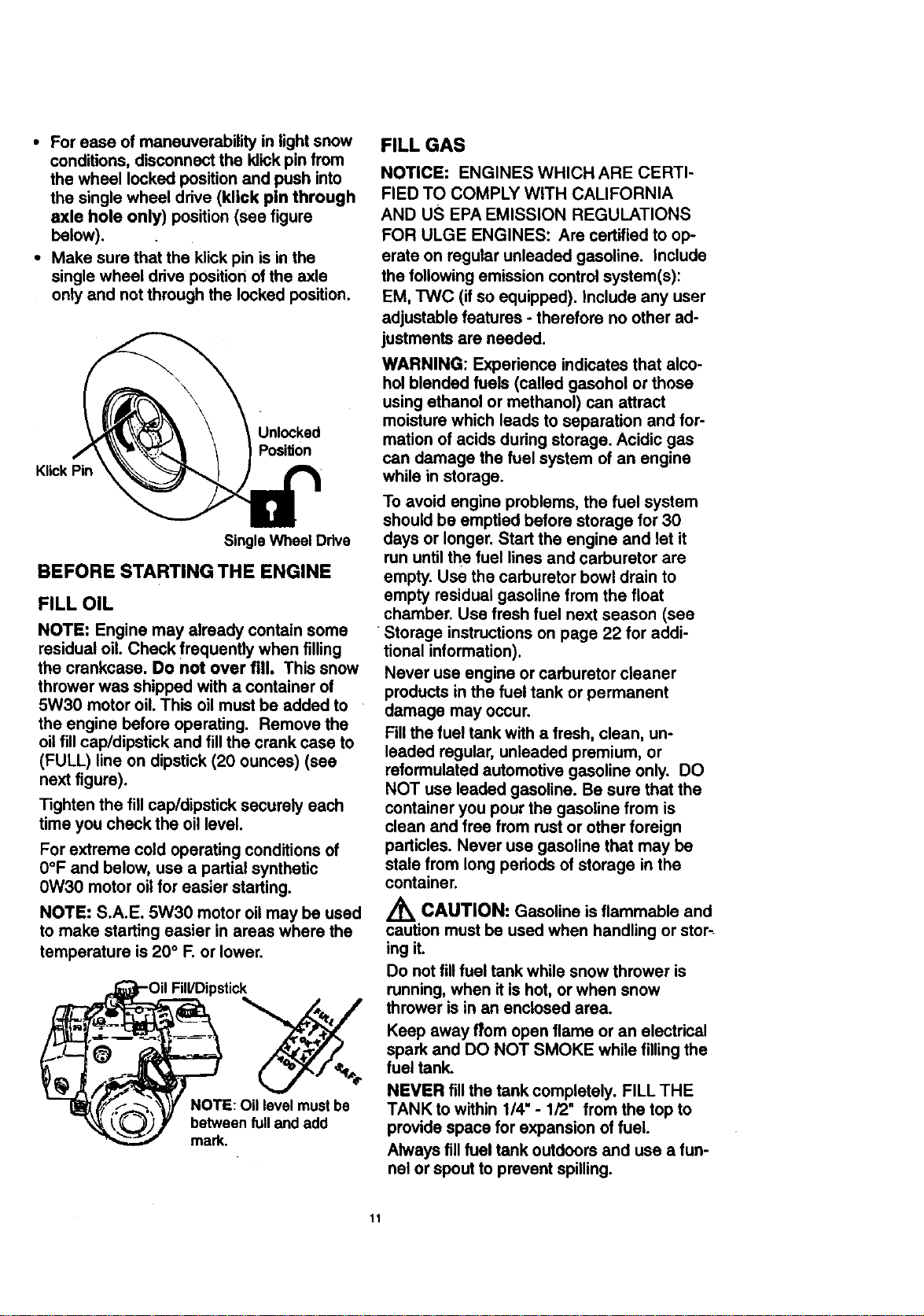
• For ease of maneuverability in light snow
conditions, disconnect the klick pin from
the wheel locked position and push into
the single wheel drive (klick pin through
axle hole only) position (see figure
below).
• Make sure that the klick pin is in the
single wheel drive position of the axle
only and not through the locked position.
KlickPin
Unlocked
Position
Single Wheel Drive
BEFORE STARTING THE ENGINE
FILL OIL
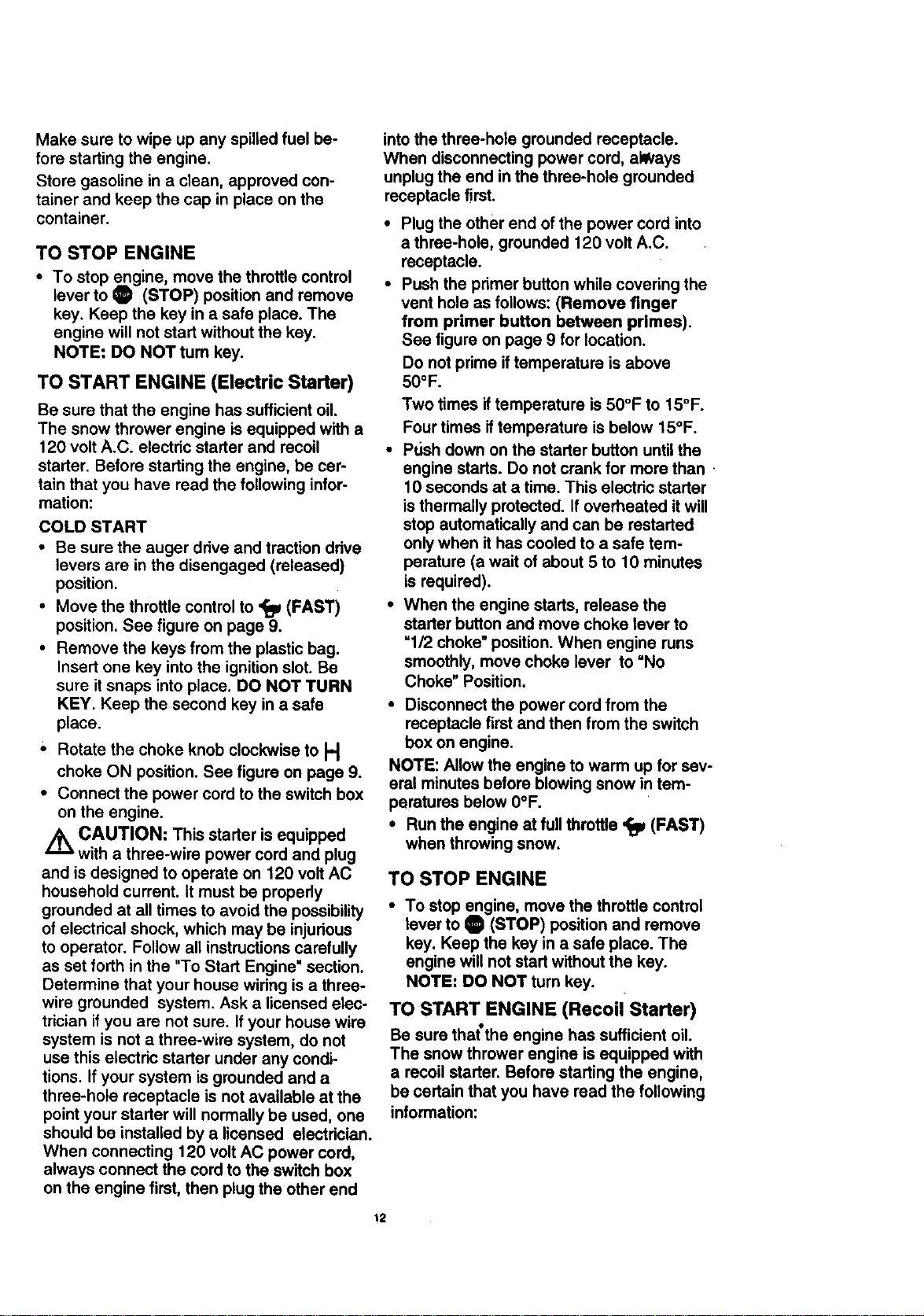
NOTE: Engine may already contain some
residual oil. Check frequently when filling
the crankcase. Do not over fill. This snow
thrower was shipped with a container of
5W30 motor oil. This oil must be added to
the engine before operating. Remove the
oil fill cap/dipstick and fill the crank case to
(FULL) line on dipstick (20 ounces) (see
next figure).
Tighten the fillcap/dipsticksecurelyeach
time you checkthe oil level.
For extreme cold operating conditions of
0°F and below, use a partial synthetic
0W30 motor oil for easier starting.
NOTE: S.A.E. 5W30 motor oil may be used
to make starting easier in areas where the
temperature is 20 ° F. or lower.
Fill/Dipstick
NOTE: Oil level mustbe
between full and add
mark.
FILL GAS
NOTICE: ENGINES WHICH ARE CERTI-
FIED TO COMPLY WITH CALIFORNIA
AND US EPA EMISSION REGULATIONS
FOR ULGE ENGINES: Are certified to op-
erate on regular unleaded gasoline. Include
the following emission control system(s):
EM, TWC (if so equipped). Include any user
adjustable features - therefore no other ad-
justmants are needed.
WARNING: Experience indicates that alco-
hol blended fuels (called gasohol or those
using ethanol or methanol) can attract
moisture which leads to separation and for-
mation of acids during storage. Acidic gas
can damage the fuel system of an engine
while in storage.
To avoid engine problems, the fuel system
should be emptied before storage for 30
days or longer. Start the engine and let it
run until the fuel lines and carburetor are
empty. Use the carburetor bowl drain to
empty residual gasoline from the float
chamber. Use fresh fuel next season (see
•Storage instructions on page 22 for addi-
tional information).
Never use engine or carburetor cleaner
products in the fuel tank or permanent
damage may occur.
Fill the fuel tank with a fresh, clean, un-
leaded regular, unleaded premium, or
reformulated automotive gasoline only. DO
NOT use leaded gasoline. Be sure that the
container you pour the gasoline from is
clean and free from rust or other foreign
particles. Never use gasoline that may be
stale from long periods of storage in the
container.
/_ CAUTION: Gasoline is flammable and
caution must be used when handling or stor_
ing it.
Do not fill fuel tank while snow thrower is
running, when it is hot, or when snow
thrower is in an enclosed area.
Keep away from open flame or an electrical
spark and DO NOT SMOKE while filling the
fuel tank.
NEVER fill the tank completely. FILL THE
TANK to within 1/4" - 1/2" from the top to
provide space for expansion of fuel.
Always fill fuel tank outdoors and use a fun-
nel or spout to prevent spilling.
11
Make sure to wipe up any spilled fuel be-
fore starting the engine.
Store gasoline in a clean, approved con-
tainer and keep the cap in place on the
container.
TO STOP ENGINE
• To stop engine, move the throttle control
lever to O (STOP) position and remove
key. Keep the key in a safe place. The
engine will not start without the key.
NOTE: DO NOT turn key.
TO START ENGINE (Electric Starter)
Be sure that the engine has sufficient oil.
The snow thrower engine is equipped with a
120 volt A.C. electric starter and recoil
starter. Before starting the engine, be cer-
tain that you have read the following infor-
mation:
COLD START
• Be sure the auger drive and traction drive
levers are in the disengaged (released)
position.
• Move the throttle control to '_ (FAST)
position. See figure on page 9.
• Remove the keys from the plastic bag.
Insert one key into the ignition slot. Be
sure it snaps into place. DO NOT TURN
KEY. Keep the second key in a safe
place.
' Rotate the choke knob clockwise to H
choke ON position. See figure on page 9.
• Connect the power cord to the switch box
on the engine.
Z_ CAUTION: This starter is equipped
with a three-wire power cord and plug
and is designed to operate on 120 volt AC
household current. It must be properly
grounded at all times to avoid the possibility
of electrical shock, which may be injurious
to operator. Follow all instructions carefully
as set forth in the "To Start Engine' section.
Determine that your house wiring is a three-
wire grounded system. Ask a licensed elec-
trician if you are not sure. If your house wire
system is not a three-wire system, do not
use this electric starter under any condi-
tions. If your system is grounded and a
three-hole receptacle is not available at the
point your starter will normally be used, one
should be installed by a licensed electrician.
When connecting 120 volt AC power cord,
always connect the cord to the switch box
on the engine first, then plug the other end
t2
into the three-hole grounded receptacle.
When disconnecting power cord, allVays
unplug the end in the three-hole grounded
receptacle first.
• Plug the other end of the power cord into
a three-hole, grounded 120 volt A.C.
receptacle.
• Push the primer button while covering the
vent hole as follows: (Remove finger
from primer button between primes).
See figure on page 9 for location.
Do not prime iftemperature is above
5O°F.
Two times if temperature is 50°F to 15°F.
Four times if temperature is below 15°F.
• Pt_sh down on the starter button until the
engine starts. Do not crank for more than
10 seconds at a time. This electric starter
is thermally protected. If overheated it will
stop automatically and can be restarted
only when it has cooled to a safe tem-
perature (a wait of about 5 to 10 minutes
is required).
• When the engine starts, release the
starter button and move choke lever to
_1/2 choke" position. When engine runs
smoothly, move choke lever to "No
Choke" Position.
• Disconnect the power cord from the
receptacle first and then from the switch
box on engine.
NOTE: Allow the engine to warm up for sev-
eral minutes before blowing snow in tem-
peratures below 0°F.
• Run the engine at full throttle '_p (FAST)
when throwing snow.
TO STOP ENGINE
• To stop engine, move the throttle control
lever to O (STOP) position and remove
key. Keep the key in a safe place. The
engine will not start without the key.
NOTE: DO NOT turn key.
TO START ENGINE (Recoil Starter)
Be sure that the engine has suff=clent oral.
The snow thrower engine is equipped with
a recoil starter. Before starting the engine,
be certain that you have read the following
information:
COLD START
• Be sure the auger drive and traction drive
levers are in the disengaged (released)
position.
• Move the throttle control to '_ (FAST)
position. See figure on page 9 for loca-
tion.
• Remove the keys from the plastic bag. In-
sert one key into the ignition slot. Be sure
it snaps into place. DO NOT TURN KEY.
Keep the second key in a safe place.
• Rotate the choke knob clockwise to H
choke ON position. See figure on page 9.
• Push the primer button, see figure on
page 9, while covering the vent hole as
follows: (Remove finger from primer
button between primes).
Do not prime if temperature is above
50oR
Two times if temperature is 50°F to
15°F.
Four times if temperature is below 15°F.
• Pull the recoil starter handle rapidly. Do
not allow the handle to snap back, but al-
low itto rewind slowly while keeping a
firm hold on the starter handle.
• As engine starts warms up move choke
lever to "1/2 choke" position. When engine
runs smoothly, move choke lever to =No
Choke" Position
NOTE: Allow the engine to warm up for sev-
eral minutes before blowing snow in
temperatures below 0°F.
• Run the engine at full throttle ,_ (FAST)
when throwing snow.
WARM START
If restarting a warm engine after a short
shutdown, leave choke at (OFF) and do not
push the primer button. If the engine fails to
start, follow the Cold Start instructions
above.
FROZEN RECOIL STARTER
If the starter Is frozen and will not turn
engine:
• Pull as much rope out of the starter as
possible.
• Release the starter handle and let it snap
back against the starter.
If the starter still fails to turn engine, repeat
the two previous steps until the starter en-
gages. Then continue with the directions for
cold start.
To help prevent possible freeze-up of recoil
starter and engine controls, proceed as fol-
lows after each snow removal job.
• With the engine running, pull the
starter rope hard with a continuous full
arm stroke three or four times. Pulling of
starter rope will produce a loud clattering
sound. This is not harmful to the engine
or starter.
With the engine not running, wipe all
snow and moisture from the carburetor
cover in area of control levers. Also move
throttle control, choke control, and starter
handle several times.
/_ CAUTION: Never run engine indoors
or in enclosed, poorly ventilated areas.
Engine exhaust contains CARBON MON-
OXIDE, AN ODORLESS AND DEADLY
GAS. Keep hands, feet, hair and loose
clothing away from any moving parts on en-
gine and snow thrower.
WARNING: Temperature of muffler and
nearby areas may exceed 150 ° F. Avoid
these areas.
DO NOT allow children or young teenagers
to operate or be near snow thrower while it
is operating.
Z_ CAUTION: Do no attempt to remove
any item that may become lodged in
auger without taking the following precau-
tions:
• Release auger drive and traction drive
levers.
• Move throttle lever to stop position.
• Remove (DO NOT TURN) ignition key.
• Disconnect spark plug wire.
• Do not place your hands in the auger or
discharge chute. Use a pry bar.
SNOW THROWING TIPS
For maximum snow thrower efficiency in
removing snow, adjust ground speed,
NEVER the throttle. Go slower in deep,
freezing, or wet snow. If the tracks slip,
reduce forward speed. The engine is de-
signed to deliver maximum performance
at full throttle and should be run at this
power setting at all times. Most efficient
13
snow blowing is accomplished when the
snow is removed immediately after it
falls.
• For complete snow removal, slightly over-
lap each path previously taken. Use
more overlap in deep snow to prevent
overloading.
• The snow should be discharged down
wind whenever possible. In windy condi-
tions, lower the chute deflector to direct
discharged snow close to the ground,
where it is less likely to blow into un-
wanted areas.
• For normal usage, set the skids so that
the scraper bar is 1/8" above the skids.
For extremely hard-packed snow sur-
faces, adjust the skids upward so that the
scraper bar touches the ground.
• On gravel or crushed rock surfaces, set
the skids at 1-1/4" below the scraper bar
(See To Adjust Skids Height paragraph
on page 17). Stones and gravel must not
be picked up and thrown by the machine.
CUSTOMER RESPONSIBILITIES
After the snow throwing job has been
completed, allow the engine to idle for a
few minutes, which will melt snow and
accumulated ice off the engine.
Clean the snow thrower thoroughly after
each use.
Remove ice and snow accumulation and
all debris from the entire snow thrower,
and flush with water (if possible) to re-
move all salt or other chemicals. Wipe
snow thrower dry.
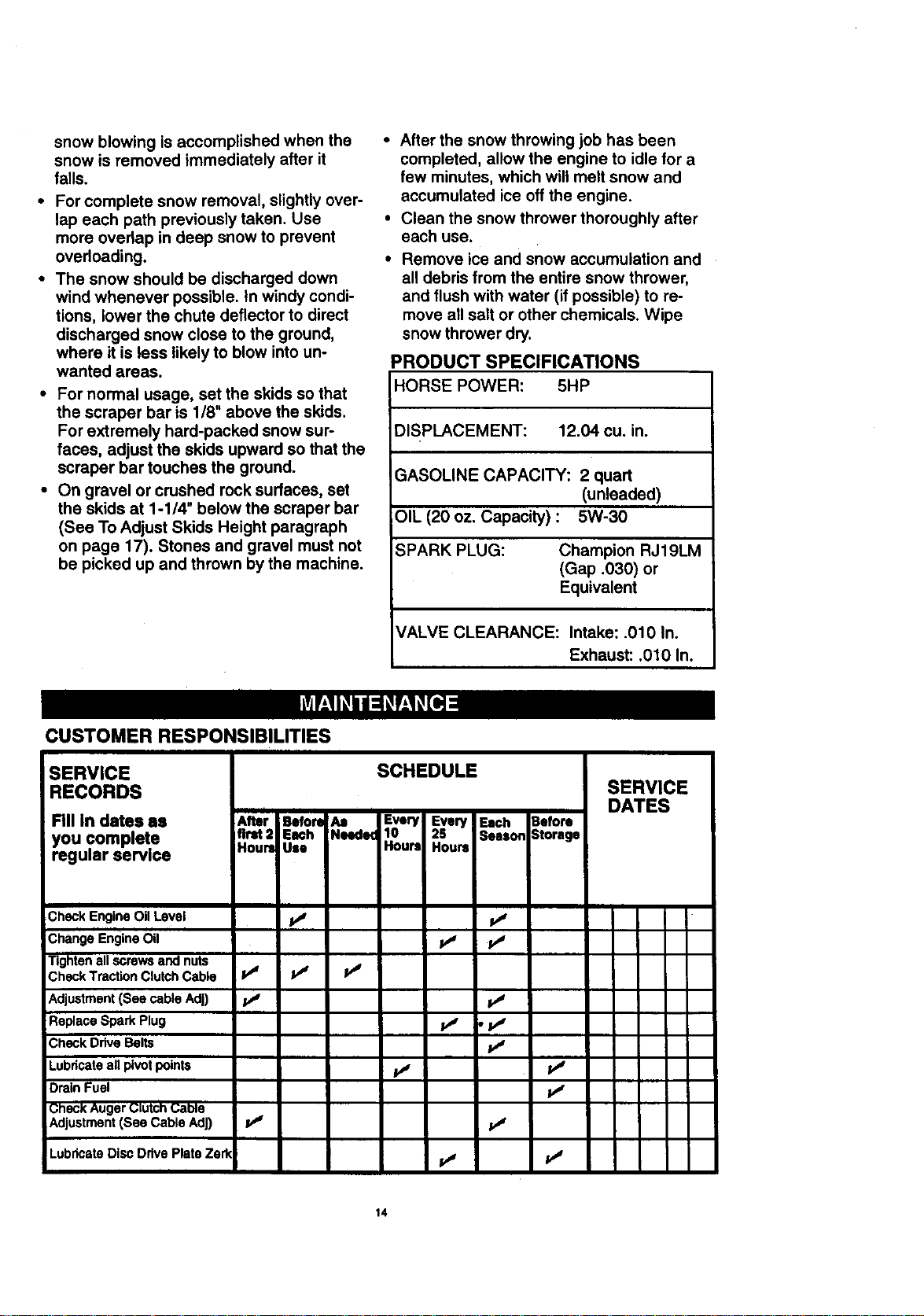
PRODUCT SPECIFICATIONS
HORSE POWER: 5HP
DISPLACEMENT: 12.04 cu. in.
;ASOLINE CAPACITY: 2 quart
(unleaded)
OIL (20 oz. Capacity) : 5W-30
;PARK PLUG: Champion RJ19LM
(Gap .030) or
Equivalent
VALVE CLEARANCE: Intake: .010 In.
Exhaust: .010 In.
SERVICE
RECORDS
RII in dates as
you complete
regular service
SCHEDULE
I
After Before Aa Every Every Each 3afore
flrM:l Each Neede_ 10 2S Season 3torage
Houri Use Hours Hours
SERVICE
DATES
I
Check Engine OilLevel V/ ivj
Change Engine Oil p_ lv_
Tightenall screws and nuts
Check TractionClutchCable I_ tJ V /
Adjustment(See cable AdD If V/
Replace Spark Plug _ , i,_
_heckDrive Belts p4
Lubdcateall pivot points V4 iJ
DrainFuel 1_'
Check:Auger ClutchCal)le
Adjustment(See Cable AdJ) p,I Ivj
LubdcateDisc Drive Plate Zerk ivj iv**
14
GENERALRECOMMENDATIONS
The warranty on this snow thrower does not
cover items that have been subjected to op-
erator abuse or negligence. To receive full
value from the warranty, the operator must
maintain the snow thrower as instructed in
this manual. The maintenance chart is pro-
vided to assist the operator in properly
maintaining the snow thrower.
Some adjustments will need to be made pe-
riodically to properly maintain your snow
thrower.
AFTER FIRST USE
• Check for any loose or damaged pads.
• Tighten any loose fasteners.
• Check and maintain the auger.
• After each use. remove all snow and slush
off the snow thrower to prevent freezing of
auger or controls.
• Check controls to make sure they are
functioning properly.
• If any parts are worn or damaged, replace
immediately.
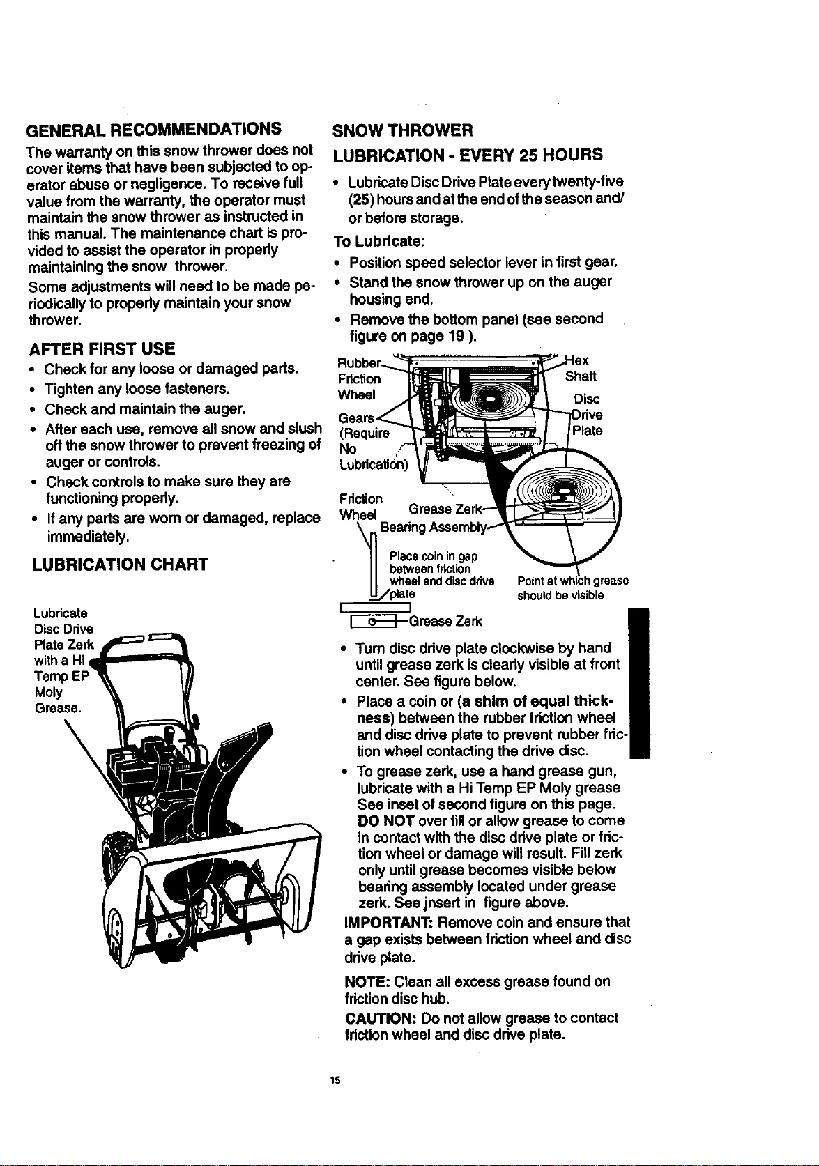
LUBRICATION CHART
Lubricate
Disc Drive
Plate Zerk
witha Hi
Temp
Moly
Grease.
\
SNOW THROWER
LUBRICATION - EVERY 25 HOURS
• Lubricate Disc Drive Plate every twenty-five
(25) hours and at the end of the season and/
or before storage.
To Lubricate:
• Position speed selector isver in first gear.
• Stand the snow thrower up on the auger
housing end.
• Remove the bottom panel (see second
figure on page 19 ).
Friction Shaft
Wheel Disc
(Require
No
Fri_on
Wheel
Bearing
Placecoiningap
betweenfriction
wheelanddiscdrive
plate shouldbevisible
r---__l
E_E_--Grease Zerk
1grease
•Tum disc drive plate clockwise by hand
until grease zerk is clearly visible at front
center. See figure below.
• Place a coin or (a shim of equal thick-
ness) between the rubber friction wheel
and disc drive plate to prevent rubber fric-
tion wheel contacting the drive disc.
• To grease zerk, use a hand grease gun,
lubricate with a Hi Temp EP Moly grease
See inset of second figure on this page.
DO NOT over fill or allow grease to come
in contact with the disc drive plate or fric-
tion wheel or damage will result. Fill zerk
only until grease becomes visible below
bearing assembly located under grease
zerk. See,insed in figure above.
IMPORTANT: Remove coin and ensure that
a gap exists between friction wheel and disc
drive plate.
NOTE: Clean all excess grease found on
friction disc hub.
CAUTION: Do not allow grease to contact
friction wheel and disc drive plate.
15
LUBRICATION
• Hex Shaft and Gears - Hex shaft and
gears require no lubrication. All bearings
and bushings are lifetime lubricated and
require no maintenance.
NOTE: Any greasing or oiling of the above
components can cause contamination of
the friction wheel. If the disc drive plate or
friction wheel comes in contact with grease
or oil, damage to the friction wheel will re-
sult.
Should grease or oil come in contact with
the disc drive plate or friction wheel, be sure
to clean the plate and wheel thoroughly.
NOTE: For storage, the hex shaft and
gears should be wiped with 5W-30 motor oil
to prevent rusting. See figure above.
• Auger Gear Box - The auger gear box
has been factory lubricated for life. If for
some mason lubricant should leak out,
have auger gear case checked by a com-
petent repairman.
ENGINE
LUBRICATION
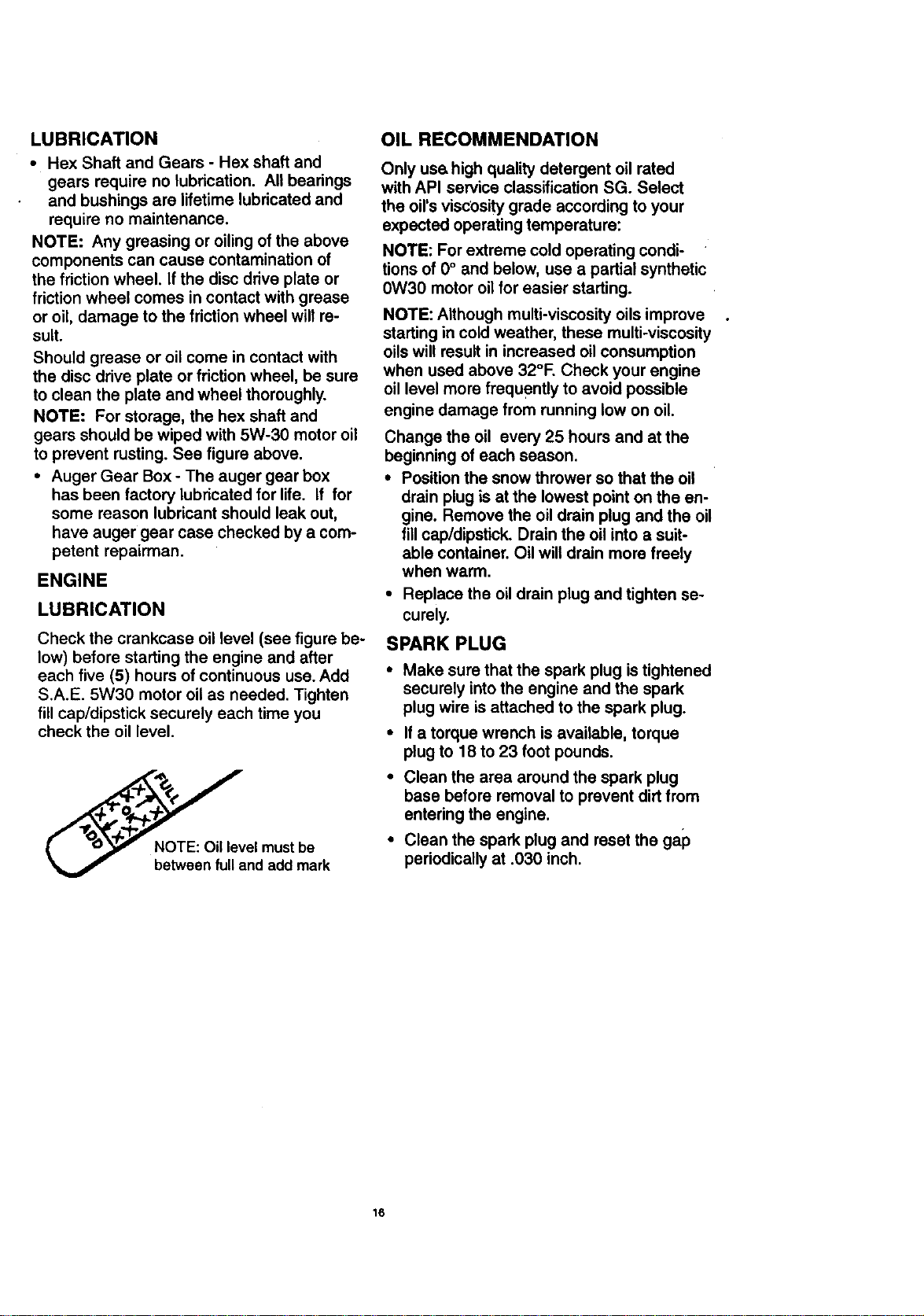
Check the crankcase oil level (see figure be-
low) before starting the engine and after
each five (5) hours of continuous use. Add
S.A.E. 5W30 motor oil as needed. Tighten
fill cap/dipstick securely each time you
check the oil level.
NOTE: Oil level must be
between fulland add mark
OIL RECOMMENDATION
Only use high quality detergent oil rated
with API service classification SG. Select
the oil's viscosity grade according to your
expected operating temperature:
NOTE: For extreme cold operating condi-
tions of 0° and below, use a partial synthetic
0W30 motor oil for easier starting.
NOTE: Although multi-viscosity oils improve
starting in cold weather, these multi-viscosity
oils will result in increased oilconsumption
when used above 32°F. Check your engine
oil level more frequently to avoid possible
engine damage from running low on oil.
Change the oil every 25 hours and at the
beginning of each season.
• Position the snow thrower so that the oil
drain plug is at the lowest point on the en-
gine. Remove the oil drain plug and the oil
fill cap/dipstick. Drain the oil into a suit-
able container. Oil will drain more freely
when warm.
• Replace the oil drain plug and tighten se-
curely.
SPARK PLUG
• Make sure that the spark plug is tightened
securely into the engine and the spark
plug wire is attached to the spark plug.
• If a torque wrench is available, torque
plug to 18 to 23 foot pounds.
• Clean the area around the spark plug
base before removal to prevent dirt from
entering the engine.
• Clean the spark plug and reset the gap
periodically at .030 inch.
16
Z_ CAUTION: Always disconnect the
spark plug wire and tie back away from
the plug before making any adjustments
or repairs.
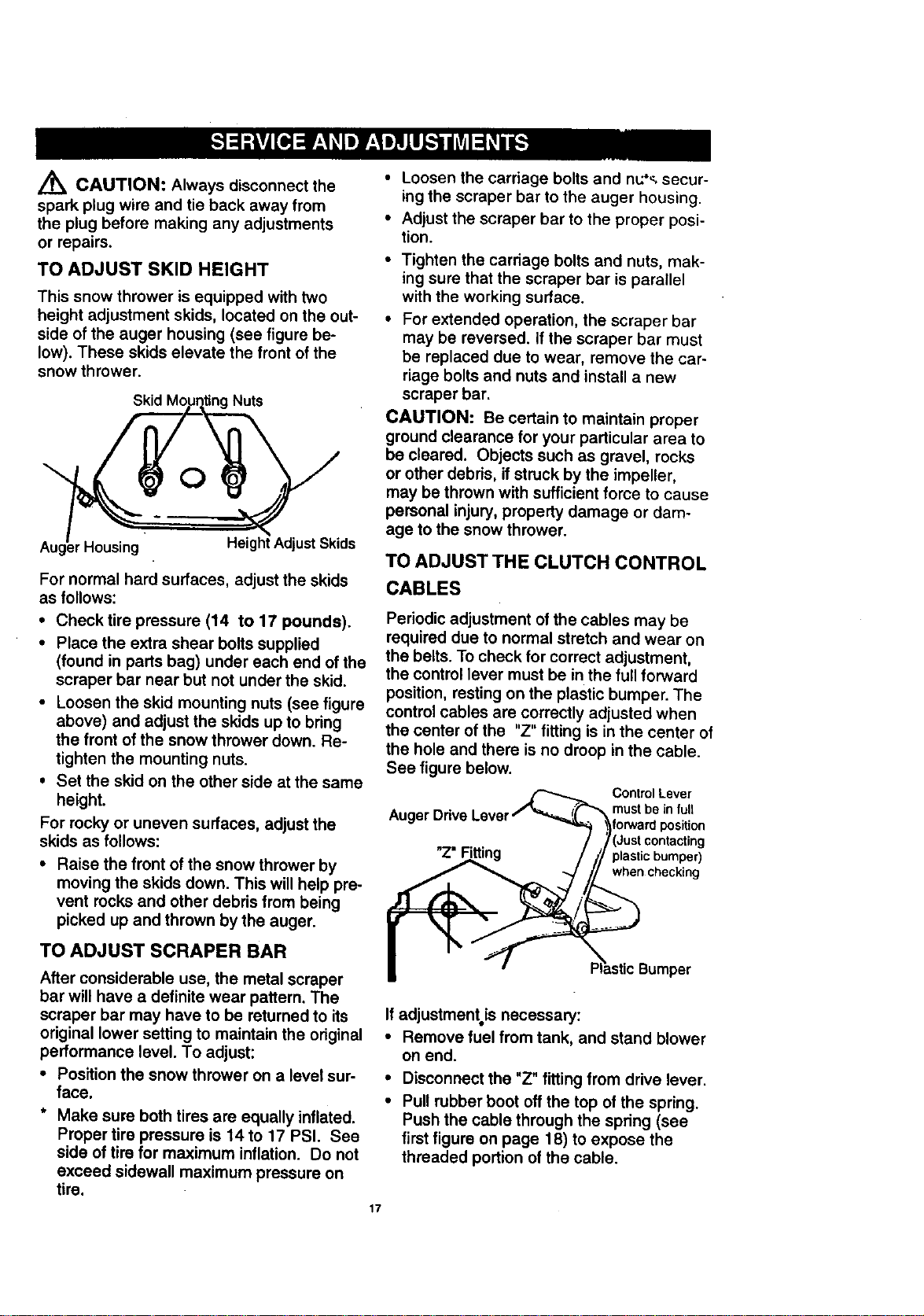
TO ADJUST SKID HEIGHT
This snow thrower is equipped with two
height adjustment skids, located on the out-
side of the auger housing (see figure be-
low). These skids elevate the front of the
snow thrower.
Nuts
O
_rHousing
Height AdjustSkids
For normal hard surfaces, adjust the skids
as follows:
• Checktire pressure (14 to 17 pounds).
• Place the extra shear bolts supplied
(found in parts bag) under each end of the
scraper bar near but not under the skid.
• Loosen the skid mounting nuts (see figure
above) and adjust the skids up to bring
the front of the snow thrower down. Re-
tighten the mounting nuts.
• Set the skid on the other side at the same
height.
For rocky or uneven surfaces, adjust the
skids as follows:
• Raise the front of the snow thrower by
moving the skids down. This will help pre-
vent rocks and other debris from being
picked up and thrown by the auger.
TO ADJUST SCRAPER BAR
After considerable use, the metal scraper
bar will have a definite wear pattern. The
scraper bar may have to be returned to its
original lower setting to maintain the original
performance level. To adjust:
• Position the snow thrower on a level sur-
face.
* Make sure both tires are equally inflated.
Proper tire pressure is 14 to 17 PSI. See
side of tire for maximum inflation. Do not
exceed sidewall maximum pressure on
tire.
• Loosen the carriage bolts and nu'_, secur-
ing the scraper bar to the auger housing.
• Adjust the scraper bar to the proper posi-
tion.
• Tighten the carriage bolts and nuts, mak-
ing sure that the scraper bar is parallel
with the working surface.
• For extended operation, the scraper bar
may be reversed. If the scraper bar must
be replaced due to wear, remove the car-
riage bolts and nuts and install a new
scraper bar.
CAUTION: Be certain to maintain proper
ground clearance for your particular area to
be cleared. Objects such as gravel, rocks
or other debris, if struck by the impeller,
may be thrown with sufficient force to cause
personal injury, property damage or dam-
age to the snow thrower.
TO ADJUST THE CLUTCH CONTROL
CABLES
Periodic adjustment of the cables may be
required due to normal stretch and wear on
the belts. To check for correct adjustment,
the control lever must be in the full forward
position, resting on the plastic bumper. The
control cables are correctly adjusted when
the center of the "Z" fitting is in the center of
the hole and there is no droop in the cable.
See figure below.
Aug,
ControlLever
must be in fuU
plastic bumper)
when checking
_astic Bumper
If adjustmentis necessary:
• Remove fuel from tank, and stand blower
on end.
• Disconnect the "Z" fitting from drive lever.
• Pull rubber boot off the top of the spring.
Push the cable through the spring (see
first figure on page 18) to expose the
threaded portion of the cable.
17
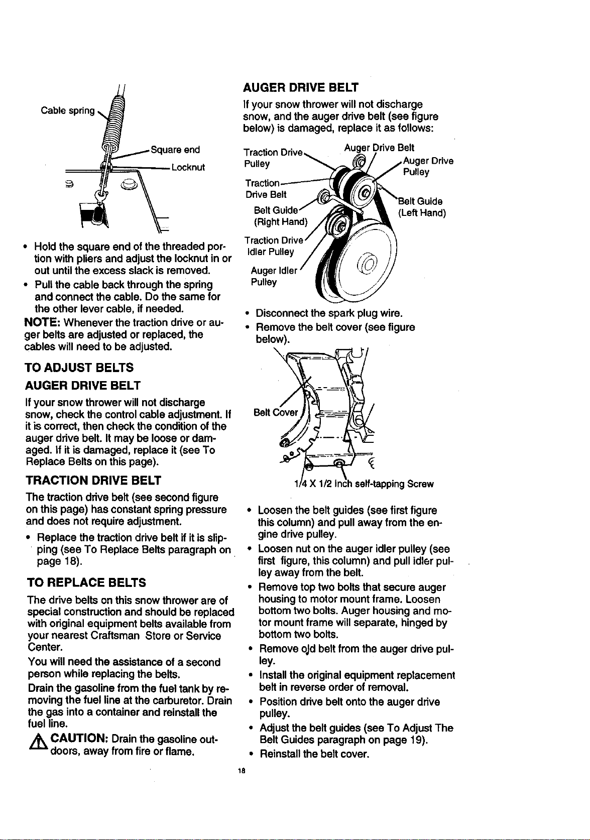
AUGER DRIVE BELT
If your snow thrower will not discharge
snow, and the auger drive belt (see figure
below) is damaged, replace it as follows:
Traction Auger Drive Belt
Pulley .=rDrive
Pulley
DriveBelt
• Hold the square end of the threaded per- Idler
tion with pliers and adjust the Iocknut in or
out until the excess slack is removed. Aug_
Pulley
• Pull the cable back through the spring
and connect the cable. Do the same for
the other lever cable, if needed.
NOTE: Whenever the traction drive or au-
ger belts are adjusted or replaced, the
cables will need to be adjusted.
TO ADJUST BELTS
AUGER DRIVE BELT
If your snow thrower will not discharge
snow, check the control cable adjustment. If
it is correct, then check the condition of the
auger drive belt. It may be loose or dam-
aged. If it is damaged, replace it(see To
Replace Belts on this page).
TRACTION DRIVE BELT
The traction drive ball (see second figure
on this page) has constant spring pressure
and does not require adjustment.
• Replace the traction drive belt if it is slip-
ping (see To Replace Belts paragraph on
page 18).
TO REPLACE BELTS
The drive belts on this snow thrower are of
special construction and should be replaced
with original equipment belts available from
your nearest Craftsman Store or Service
Center.
You will need the assistance of a second
parson while replacing the belts.
Drain the gasoline from the fuel tank by re-
moving the fuel line at the carburetor. Drain
the gas into a container and reinstall the
fuel line.
Z_ CAUTION: Drainthe gasoline out-
doors, away from fire orflame.
(LeftHand)
• Disconnect the spark plug wire.
• Remove the belt cover (see figure
below).
\
BeRCover
Screw
18
• Loosen the belt guides (see first figure
this column) and pull away from the en-
gine drive pulley.
• Loosen nut on the auger idler pulley (see
first figure, this column) and pull idler pul-
ley away from the belt.
• Remove top two bolts that secure auger
housing to motor mount frame. Loosen
bottom two bolts. Auger housing and mo-
tor mount frame will separate, hinged by
bottom two bolts.
• Remove old belt from the auger drive pul-
ley.
• Install the original equipment replacement
belt in reverse order of removal.
• Position drive belt onto the auger drive
pulley.
• Adjust the belt guides (sea To Adjust The
Belt Guides paragraph on page 19).
• Reinstall the belt cover.
• Check clutch control cable adjustment,
see page 17.
• Reconnect spark plug wire.
TRACTION DRIVE BELT
If your snow thrower will not move forward,
check the traction drive belt (see second
figure on page 18) for wear (Check other
causes also in the Trouble Shooting Points
section). Ifthe traction drive belt needs to
be replaced, proceed as follows:
• Disconnect the spark plug wire.
• Remove the belt cover (see last figure on
page 18).
• Loosen the belt guides and putt away
from engine drive pulley (see first figure).
• Loosen nut on auger idler and pull auger
idler pulley away from belt. Note location
of idler pulley for later re-installation.
• Remove auger drive belt from engine pul-
ley.
• Pull the idler pulley away from the drive
belt, allowing belt to be positioned onto
engine pulley.
• Release idler pulley. Ensure idler pulley is
properly engaged with belt.
• Reinstall auger drive belt.
• Adjust belt guides (see To Adjust The
Belt Guides paragraph below).
• Adjust idler on auger belt.
• Reinstall the' belt cover.
• Reconnect the spark plug wire.
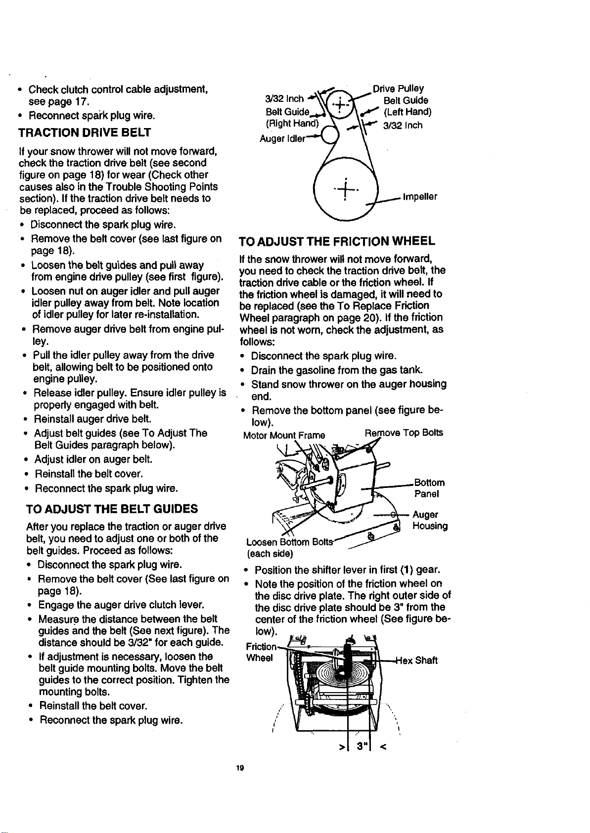
TO ADJUST THE BELT GUIDES
After you replace the traction or auger drive
belt, you need to adjust one or both of the
belt guides. Proceed as follows:
• Disconnect the spark plug wire.
• Remove the belt cover (See last figure on
page 18).
• Engage the auger drive clutch lever.
• Measure the distance between the belt
guides and the belt (See next figure). The
distance should be 3/32" for each guide.
• If adjustment is necessary, loosen the
belt guide mounting bolts. Move the belt
guides to the correct position. Tighten the
mounting bolts.
• Reinstall the belt cover.
• Reconnect the spark plug wire.
(Right Hand)
Auger
Belt Guide
f (LeftHand)
3/32 Inch
TO ADJUST THE FRICTION WHEEL
If the snow thrower will not move forward,
you need to check the traction drive belt, the
traction drive cable or the friction wheel. If
the friction wheel is damaged, it will need to
be replaced (see the To Replace Friction
Wheel paragraph on page 20). If the friction
wheel is not wom, check the adjustment, as
follows:
• Disconnect the spark plug wire.
• Drain the gasoline from the gas tank.
• Stand snow thrower on the auger housing
end.
• Remove the bottom panel (see figure be-
low).
MotorMount Frame Remove Top Bolts
Panel
Housing
(eachside)
• Position the shifter lever in first (1) gear.
• Note the position of the friction wheel on
the disc drive plate. The right outer side of
the disc drive plate should be 3" from the
center of the friction wheel (See figure be-
low).
Wheel Shaft
19
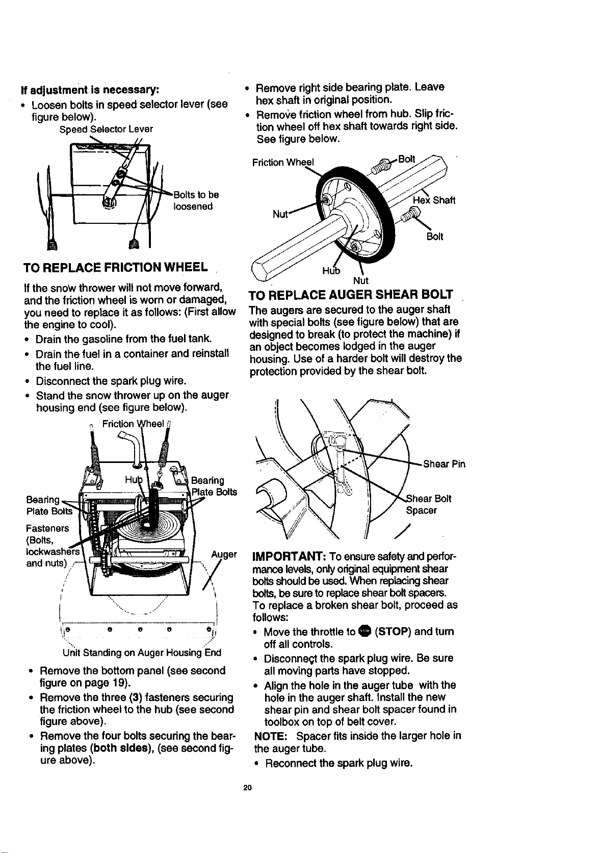
If adjustment is necessary:
• Loosen bolts in speed selector lever (see
figure below).
Speed Selector Lever
/
TO REPLACE FRICTION WHEEL
If the snoW thrower will not move forward,
and the friction wheel is worn or damaged,
you need to replace it as follows: (First allow
the engine to cool).
• Drain the gasoline from the fuel tank.
• Drain the fuel in a container and reinstall
the fuel line.
• Disconnect the spark plug wire.
• Stand the snow thrower up on the auger
housing end (see figure below).
Friction
Bearing
Plate Bolts
Fasteners
(Bolts,
ger
• Remove the bottom panel (see second
figure on page 19).
• Remove the three (3) fasteners securing
the friction wheel to the hub (see second
figure above).
• Remove the four bolts securing the bear-
ing plates (both sides), (see second fig-
ure above).
• Remove right side bearing plate. Leave
hex shaft in original position.
• Remo,_e friction wheel from hub. Slip fric-
tion wheel off hex shaft towards right side.
See figure below.
FrictionWheel
Bolt
Nut
TO REPLACE AUGER SHEAR BOLT
The augers are secured to the auger shaft
with special bolts (see figure below) that are
designed to break (to protect the machine) if
an object becomes lodged in the auger
housing. Use of a harder bolt will destroy the
protection provided by the shear bolt.
_Sph Shear Pin:!ili aroBo.
,/
IMPORTANT: To ensure safety and perfor-
manse levels, only originalequipment shear
boltsshouldbe used. When replacing shear
bolts,be sure to replace shear bolt spacers.
To replace a broken shear bolt, proceed as
follows:
• Move the throttle to O (STOP) and turn
off all controls.
• Disconne_ the spark plug wire. Be sure
all moving parts have stopped.
• Align the hole in the auger tube with the
hole in the auger shaft. Install the new
shear pin and shear bolt spacer found in
toolbox on top of belt cover.
NOTE: Spacer fits inside the larger hole in
the auger tube.
• Reconnect the spark plug wire.
2O
TO ADJUSTCARBURETOR
If you think your carburetor needs adjusting,
see your nearest Authorized Craftsman
Service Center. Engine performance should
not be affected at altitudes up to 7,000 feet.
For operation at higher elevations, contact
your Authorized Craftsman Service Center.
IMPORTANT: Never tamper with the engine
governor, which is factory set for proper en-
gine speed. Overspeeding the engine
above the factory high speed setting can be
dangerous. If you think the engine-governed
high speed needs adjusting, contact your
nearest Craftsman Service Center, which
has the proper equipment and experience to
make any necessary adjustments,
TO ADJUST OR REPLACE THE
SPARK PLUG
NOTICE: This spark ignition system meets
all requirements of the Canadian Interfer-
ence-Causing Equipment Regulations.
NOTICE: This engine complies with all cur-
rent Australian and New Zealand limitaions
regarding electromagnetic interference.If
you have difficulty starting your snow
thrower, you may need to adjust or replace
the spark plug. Follow the instructions be-
low.
Replace the spark plug if the electrodes are
pitted or burned or if the porcelain is
cracked.
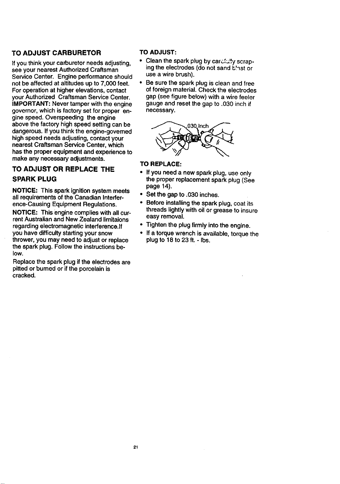
TO ADJUST:
Clean the spark plug by car_;f;t_y scrap-
ing the electrodes (do not sand b':_st or
use a wire brush).
Be sure the spark plug is clean and free
of foreign material. Check the electrodes
gap (see figure below) with a wire feeler
gauge and reset the gap to .030 inch if
necessary.
TO REPLACE:
• If you need a new spark plug, use only
the proper replacement spark plug (See
page 14).
• Set the gap to .030 inches.
• Before installing the spark plug, coat its
threads lightly with oil or grease to insure
easy removal.
• Tighten the plug firmly into the engine.
• If a torque wrench is available, torque the
plug to 18 to 23 ft. - Ibs.
21
,/_ CAUTION: Never store your snow
thrower indoors or in an enclosed, poorly
ventilated area if gasoline remains in the
tank. fumes may reach an open flame,
spark or pilot light from a fumace, water
heater, clothes dryer, cigarette, etc.
To prevent engine damage (if snow thrower is
not used for more than 30 days) follow the
steps below.
SNOW THROWER STORAGE
• Thoroughly clean the snow thrower.
• Lubricate all lubrication points (See the
Maintenance section on pages 14-16).
• Be sure that all nuts, bolts and screws are
securely fastened. Inspect all visible mov-
ing parts for damage, breakage and wear.
Replace if necessary.
• Touch up all rusted or chipped paint sur-
faces; sand lightly before painting.
• Cover the bare metal parts of the blower
housing auger and the impeller with rust
preventative, such as a spray lubricant.
NOTE: A yearly checkup or tune-up by a
Craftsman Service Center is a good way to
insure that your snow thrower will provide
maximum performance for the next season.
ENGINE STORAGE
Gasoline must be removed or treated to pre-
vent gum deposits from forming in the tank,
filter, hose, and carburetor during storage.
Also during storage, alcohol blended gaso-
line that uses ethanol or methanol (some-
times called gasohol) attracts water. It acts
on the gasoline to form acids which damage
the engine.
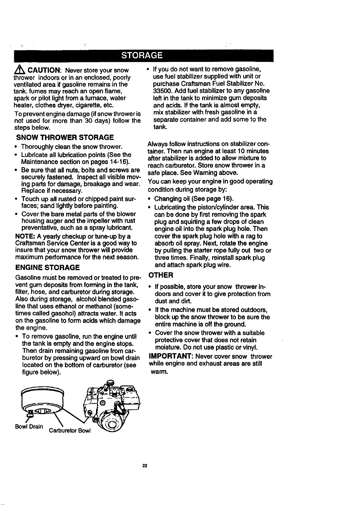
• To remove gasoline, run the engine until
the tank is empty and the engine stops.
Then drain remaining gasoline from car-
buretor by pressing upward on bowl drain
located on the bottom of carburetor (see
figure below).
• If you do not want to remove gasoline,
use fuel stabilizer supplied with unit or
purchase Craftsman Fuel Stabilizer No.
33500. Add fue ! stabilizer to any gasoline
left in the tank to minimize gum deposits
and acids. If the tank is almost empty,
mix stabilizer with fresh gasoline in a
separate container and add some to the
tank.
Always follow instructions on stabilizer con-
tainer. Then run engine at least 10 minutes
after stabilizer is added to allow mixture to
reach carburetor. Store snow thrower in a
safe place. See Waming above.
You can keep your engine in good operating
condition during storage by:
• Changing oil (See page 16).
• Lubricating the piston/cylinder area. This
can be done by first removing the spark
plug and squirting a few drops of clean
engine oil into the spark plug hole. Then
cover the spark plug hole with a rag to
absorb oil spray. Next, rotate the engine
by pulling the starter rope fully out two or
three times. Finally, reinstall spark plug
and attach spark plug wire.
OTHER
• If possible, store your snow thrower in-
doors and cover it to give protection from
dust and dirt.
• Ifthe machine must be stored outdoors,
block up the snow thrower to be sure the
entire machine is off the ground.
• Cover the snow thrower with a suitable
protective cover that does not retain
moisture. Do not use plastic or vinyl.
IMPORTANT: Never cover snow thrower
while engine and exhaust areas are still
warm.
BowlDrain
CarburetorBowl
22
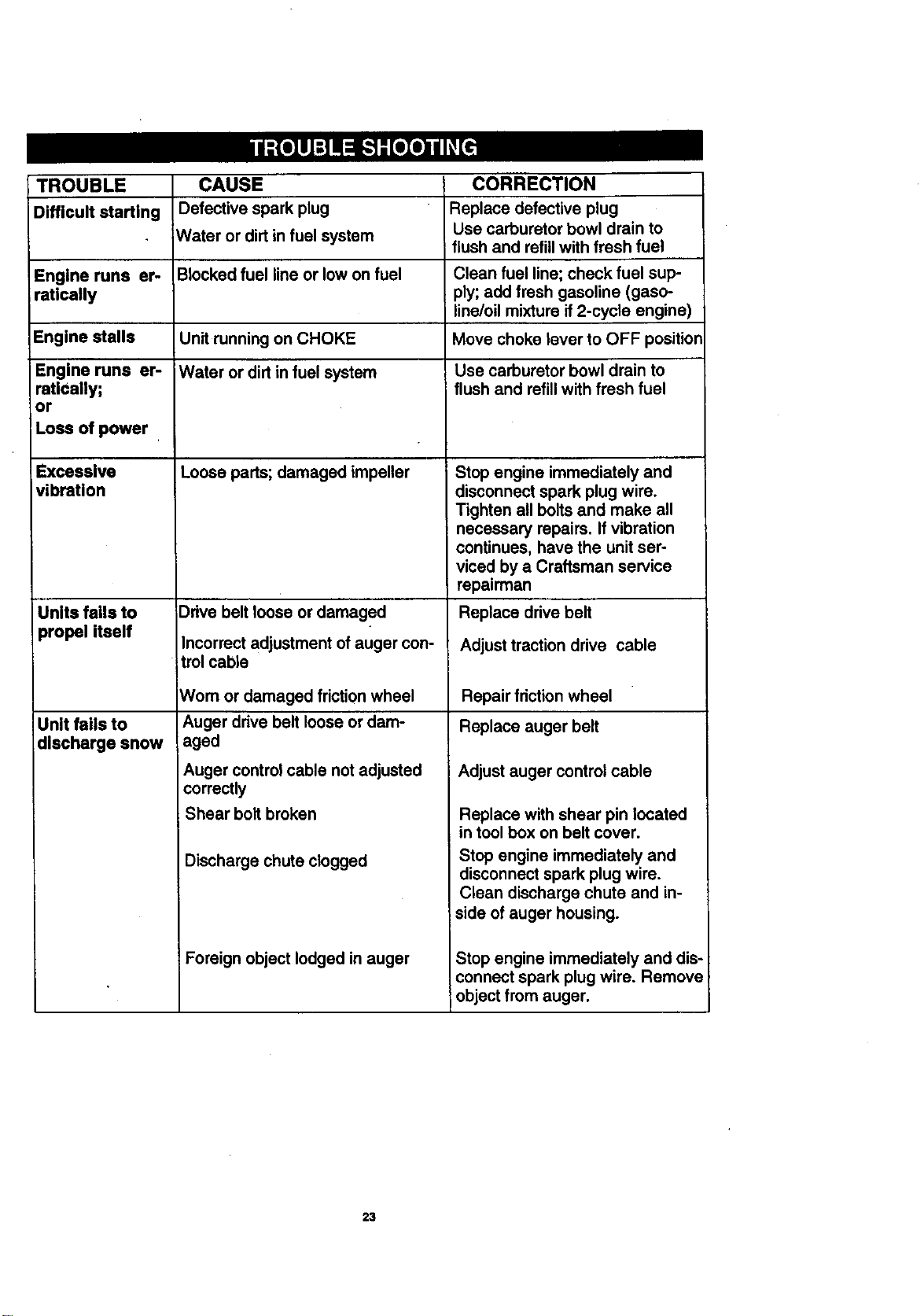
TROUBLE CAUSE CORRECTION
Difficult starting Defective spark plug Replace defective plug
Water or dirt in fuel system Use carburetor bowl drain to
flush and refill with fresh fuel
Engine runs er- Blocked fuel line or low on fuel Clean fuel line; check fuel sup-
ratically ply; add fresh gasoline (gaso-
line/oil mixture if 2-cycle engine)
Engine stalls Unit running on CHOKE Move choke lever to OFF position
Engine runs er- Water or dirt in fuel system Use carburetor bowl drain to
ratiCally; flush and refill with fresh fuel
or
Loss of power
Excessive Loose parts; damaged impeller
vibration
Units fails to
_ropel itself
Unit fails to
discharge snow
_)dve belt loose or damaged
Incorrect adjustment of auger con-
trol cable
Wom or damaged friction wheel
Auger drive belt loose or dam-
aged
Auger control cable not adjusted
correctly
Shear bolt broken
Discharge chute clogged
Foreign object lodged in auger
Stop engine immediately and
disconnect spark plug wire.
Tighten all bolts and make all
necessary repairs. If vibration
continues, have the unit ser-
viced by a Craftsman service
repairman
Replace drive belt
Adjust traction drive cable
Repair friction wheel
Replace auger belt
Adjust auger control cable
Replace with shear pin located
in tool box on belt cover.
Stop engine immediately and
disconnect spark plug wire.
Clean discharge chute and in-
side of auger housing.
Stop engine immediately and dis-
connect spark plug wire. Remove
object from auger.
23
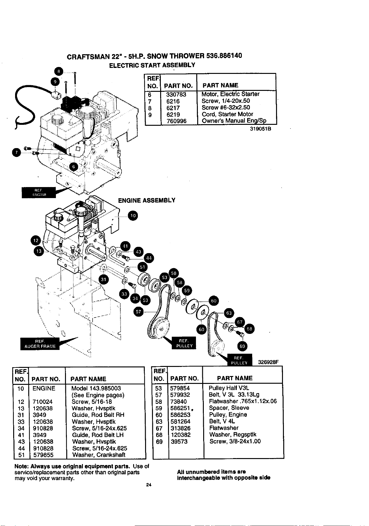
CRAFTSMAN 22" - 5H.P. SNOW THROWER 536.886140
ELECTRIC START ASSEMBLY
REF
NO. PART NO,
6 330783
7 6216
8 6217
9 6219
760996
PART NAME
Motor, ElectricStarter
Screw, 1/4-20x.50
Screw #6-32x2.50
Cord, Starter Motor
Owner's Manual EnQ/Sp
319051B
\
i¾.
ENGINE ASSEMBLY
.J
@
REF
NO. _ARTNO. PARTNAME
10 ENGINE
12 710024
13 120638
31 3949
33 120638
34 910828
41 3949
43 120638
44 910828
51 579855
Model 143.985003
(See Engine pages)
Screw, 5/16-18
Washer, Hvsptlk
Guide, Rod Belt RH
Washer, HvspUk
Screw, 5116-24x.625
Guide, Rod Belt LH
Washer, Hvsptlk
Screw, 5/16-24x.625
Washer, Crankshaft
Note: Always use original equipment parts. Use of
service/replacement parts other than original parts
may void your warranty.
24
REF.
NO. PART NO. PART NAME
53
57
58
59
60
63
67
68
69
579854
,579932
73840
586251,
586253
581264
313826
120382
39573
Pulley Half V3L
Belt,V 3L 33.13Lg
Flatwasher .765x1.12x.06
Spacer, Sleeve
Pulley, Engine
Belt,V 4L
Flatwasher
Washer, Regsptlk
Screw, 3/8-24xl .00
All unnumbered items are
Interchangeable with opposite side
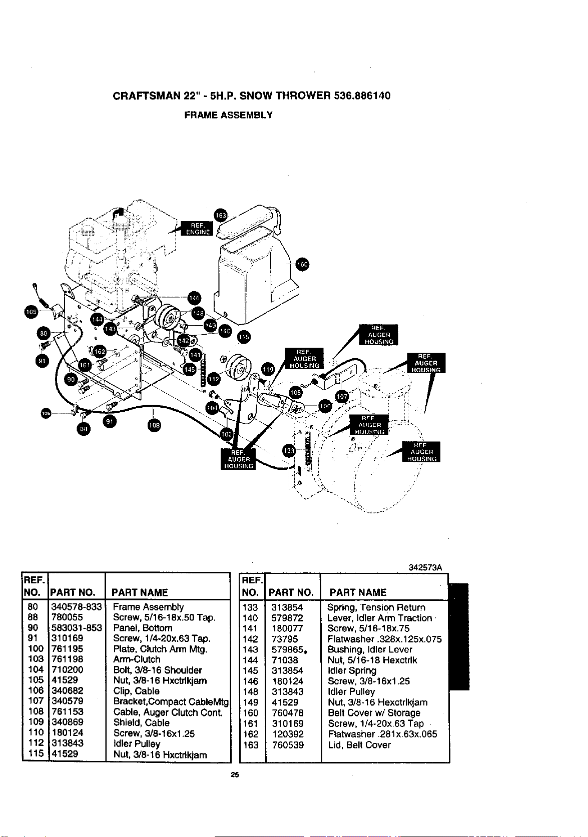
CRAFTSMAN 22" -5H.P. SNOW THROWER 536.886140
FRAME ASSEMBLY
0
@
0 o ®
...'
REF.
NO.
80
88
90
91
100
103
104
; 105
106
107
108
109
110
112
115
342573A
PART NO.
340578-833
780055
583031-853
310169
761195
761198
710200
41529
340682
340579
761153
340869
180124
313843
41529
PART NAME
Frame Assembly
Screw, 5/16-18x.50 Tap.
Panel, Bottom
Screw, 1/4-20x.63 Tap.
Plate, ClutchArm Mtg.
Arm-Clutch
Bolt,3/8-16 Shoulder
Nut, 3/8-16 Hxctdkjam
Clip, Cable
Bracket,CompactCablsMtg
Cable, Auger ClutchCont.
Shield, Cable
Screw, 3/8-16xl .25
Idler Pulley
Nut, 3/8-16 Hxctdkjam
REF.
NO.
133
140
141
142
143
144
145
146
148
149
160
161
162
163
PART NO.
313854
579872
180077
73795
579865,
71038
313854
180124
313843
41529
760478
310169
120392
760539
PART NAME
Spring, Tension Return
Lever, idler Arm Traction
Screw, 5/16-18x.75
Flatwasher .328x.125x.075
Bushing, Idler Lever
Nut, 5/16-18 Hexctrlk
Idler Spring
Screw, 3/8-16xl .25
Idler Pulley
Nut, 3/8-16 Hexctrlkjam
Belt Cover w/Storage
Screw, 1/4-20x.63 Tap
Flatwasher .281x.63x.065
Lid, Belt Cover
25
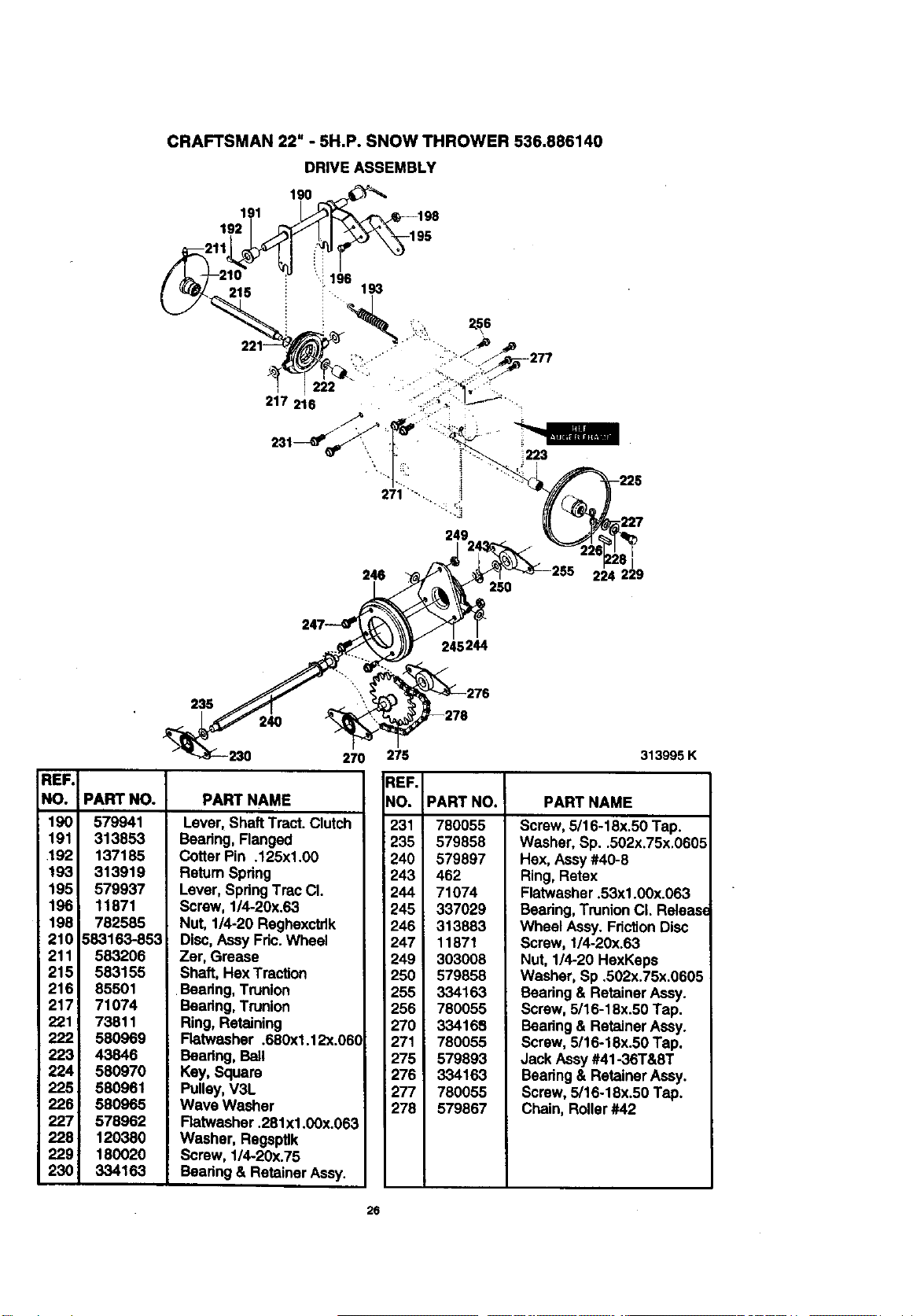
CRAFTSMAN 22" - 5H.P. SNOW THROWER 536.886140
DRIVE ASSEMBLY
190
191
192
215
249
246 224 229
250
;244
REF,
NO.
190
191
192
193
195
196
198
210
211
215
216
217
221
222
223
224
225
226
227
228
229
230
235 "'.
240
270
PART NAMEPART NO.
579941
313853
137185
313919
579937
11871
782585
583163-853
583206
583155
85501
71074
73811
580969
43846
580970
580961
580965
578962
120380
180020
334163
Lever,Shaft Tract.Clutch
Bearing, Flanged
CotterPin .125xl.00
Retum Spring
Lever, SpringTrac CL
Screw, 1/4-20x.63
Nut, 1/4-20 Reghexctdk
Disc,Assy Fric.Wheel
Zer, Grease
Shaft, HexTracUon
Bearing, Trunlon
Bearing, Trunion
Ring,Retaining
Flatwasher .680xl .12x.06(
Beadng, Bali
Key, Square
Pulley,V3L
Wave Washer
Ratwasher .281xl .00x.063
Washer, Regeptlk
Screw, 1/4-20x.75
Bearing & Retainer Assy.
275 313995K
PART NAME
REF.
NO.
231
235
240
243
244
245
246
247
249
250
255
256
270
271
275
276
277
278
PART NO.
780055
579858
579897
462
71074
337029
313883
11871
303008
579858
334163
780055
334168
780055
579893
334163
780055
579867
Screw, 5/16-18x.50 Tap.
Washer, Sp..502x.75x.0605
Hex, Assy#40-8
Ring, Retex
Flatwasher .53xl .00x.063
Bearing,TrunionCL Releas_
Wheel Assy. FrictionDisc
Screw, 1/4-20x.63
Nut, 1/4-20 HexKeps
Washer, Sp .502x.75x.0605
Bearing& Retainer Assy.
Screw, 5/16-18x.50 Tap.
Bearing & Retainer Assy.
Screw, 5/16-18x.50 Tap.
Jack Assy#41-36T&8T
Bearing& RetainerAssy.
Screw, 5/16-18x.50 Tap.
Chain, Roller#42
26
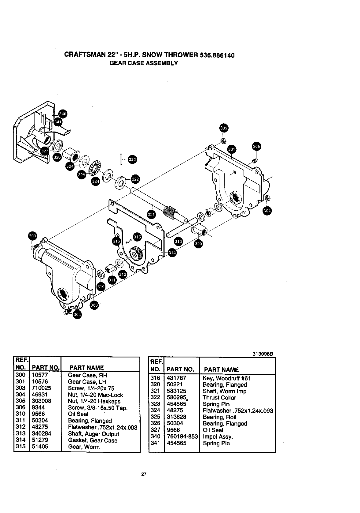
CRAFTSMAN 22" - 5H.P. SNOW THROWER 536.886140
GEAR CASE ASSEMBLY
®
®
®
REF.
NO.
300
301
303
304
305
306
310
311
312
313
314
315
PART NO.
10577
10576
710025
46931
303008
9344
9566
50304
48275
340284
51279
51405
PART NAME
Gear Case, RH
Gear Case, LH
Screw, 1/4-20x.75
Nut, 1/4-20 Mac-Lock
Nut, 1/4-20 Hexkeps
Screw, 3/8-16x.50 Tap.
Oil Seal
Bearing, Flanged
Flatwasher .752xl .24x.093
Shaft, AugerOutput
Gasket, Gear Case
Gear, Worm
REF,
NO, PART NO.
316 431787
320 50221
321 583125
322 580295o
323 454565
324 48275
325 313828
326 50304
327 9566
340 760194-853
341 454565
313996B
PART NAME
Key, Woodruff #61
Bearing, Flanged
Shaft, Worm Imp
Thrust Collar
SpringPin
Flatwasher .752xl .24x.093
Bearing, Roll
Bearing, Flanged
Oil Seal
Impel Assy.
Spring Pin
27
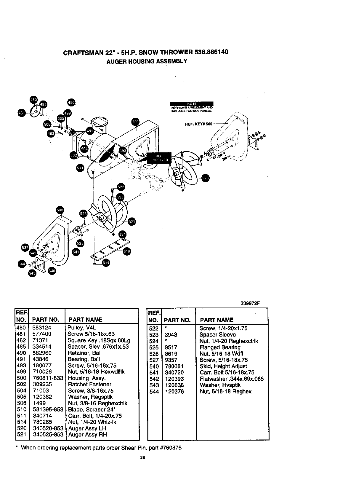
CRAFTSMAN 22" - 5H.P. SNOW THROWER 536.886140
AUGER HOUSING ASSEMBLY
@
@
REF
NO.
480
481
482
485
490
491
493
499
5O0
502
504 !
505 1
506 !
510
511
514
520
521
PART NO.
583124
577400
71371
334514
582960
43846
180077
710026
760811-833
309235
71003
120382
1499
581395-853
340714
780285
340520-853
340525-853
PART NAME
Pulley, V4L
Screw 5/16-18x.63
Square Key. 18Sqx.88Lg
Spacer, Slev .676xlx.53
Retainer, Ball
Bearing, Ball
Screw, 5/16-18x.75
Nut, 5/16-18 Hexwdfllk
Housing Assy.
Ratchet Fastener
Screw, 3/8-16x.75
Washer, Regsptlk
Nut, 3/8-16 Reghexctrlk
Blade, Scraper 24"
Carr. Bolt, 1/4-20x.75
Nutj 1/4-20 Whiz-lk
Auger Assy LH
Auger Assy RH
REF.
NO. PART NO.
522 *
523 3943
524
525 9517
526 8619
527 9357
540 780061
541 340720
542 120393
543 12063,8
544 120376
339972F
PART NAME
Screw, 1/4-20xl.75
Spacer Sleeve
Nut, 1/4-20 Reghexctdk
Flanged Bearing
Nut, 5/16-18 Wdfl
Screw, 5/16-18x.75
Skid, HeightAdjust
Carr. Bolt5/16-18x.75
Ratwasher .344x.69x.065
Washer, Hvsptlk
Nut,5/16-18 Reghex
* When ordering replacement parts order Shear Pin, part #760875
28
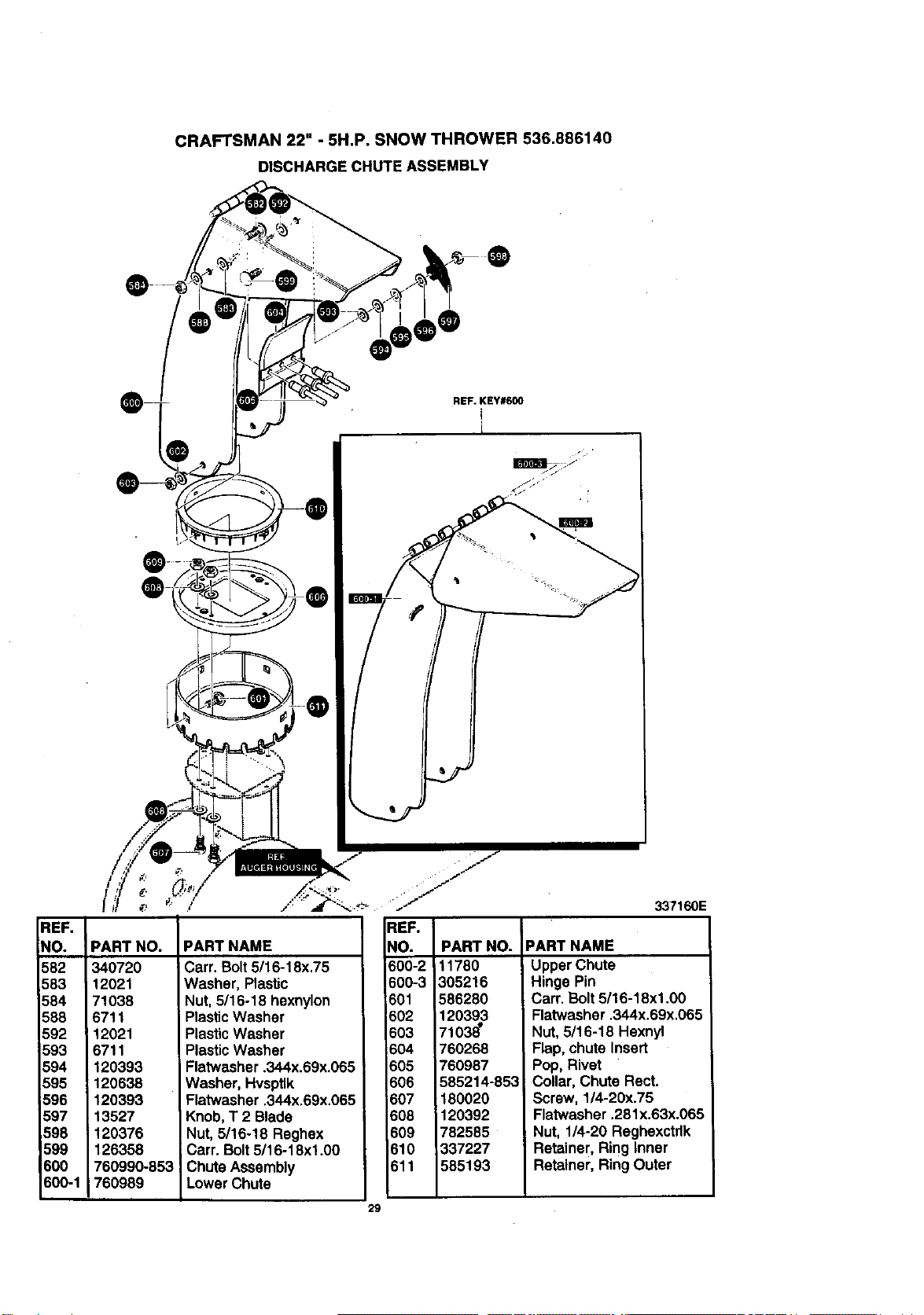
CRAFTSMAN 22" - 5H.P. SNOW THROWER 536.886140
DISCHARGE CHUTE ASSEMBLY
REF.
NO.
582
583
584
588
592
593
594
595
596
597
,598
599
BOO
500-1
PART NO.
340720
12021
71038
6711
12021
6711
120393
120638
120393
13527
120376
126358
760990-853
760989
PART NAME
Carr. Bolt5/16-18x.75
Washer, Plastic
Nut, 5/16-18 hexnylon
PlasticWasher
PlasticWasher
PlasticWasher
Flatwasher .344x.69x.065
Washer, Hvsptlk
Flatwasher .344x.69x.065
Knob,T 2 Blade
Nut, 5/16-18 Reghex
Carr. Bolt5116-18xl .00
Chute Assembly
Lower Chute
29
REF. KEY#600
i
REF.
_O. PART NO.
600-2 i11780
600-3 305216
601 586280
602 120393
603 7103_
604 760268
605 760987
606 585214-853
607 180020
608 120392
609 782585
610 337227
611 585193
337160E
PART NAME
Upper Chute
Hinge Pin
Cart. Bolt5/16-18xl.00
Flatwasher .344x.69x.065
Nut, 5/16-18 Hexnyl
Flap, chute Insert
Pop, Rivet
Collar, Chute Rect.
Screw, 1/4-20x.75
Flatwasher .281x.63x.065
Nut, 1/4-20 Reghexctrlk
Retainer, Ring Inner
Retainer, Ring Outer
@
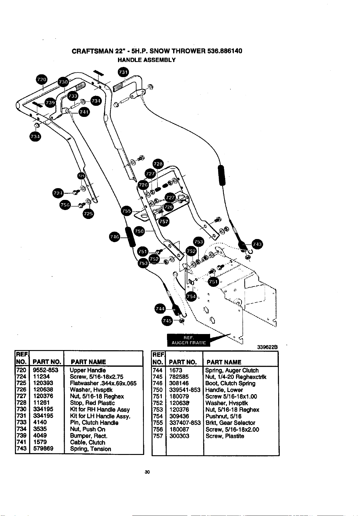
CRAFTSMAN 22" - 5H.P. SNOW THROWER 536.886140
HANDLE ASSEMBLY
@
@
REF,
NO.
720
724
725
726
727
728
730
731
733
734
739
741
743
PART NO.
9552-853
11234
120393
120638
120376
11261
334195
334195
4140
3535
4049
1579
579869
PART NAME
Upper Handle
Screw, 5/16-18x2.75
Flatwasher .344x.69x.065
Washer, HvspUk
N_, 5/16-18 Reghex
Stop, Red Pla_c
Kitfor RH Handle Assy
Kitfor LH Handle Assy.
Pin,Clutch Handle
Nut, Push On
Bumper,Rect.
Cable, Clutch
Spdng,Tension
REFI
NO.!
744
745
746
75O
751
752
753
754
755
756
757
339622B
PART NAMEPART NO.
1673
782585
308146
339541-853
180079
12063_
120376
309436
337407-853
180087
300303
Spring,Auger Clutch
Nut, 114-20 Reghexctrlk
Boot,Clutch Spdng
Handle, Lower
Screw 5/16-18xl .00
Washer, Hvsptlk
Nut,5/16-18 Reghex
Pushnut,5/16
Brkt,Gear Selector
Screw, 5/16-18x2.00
Screw, Plastite
3O
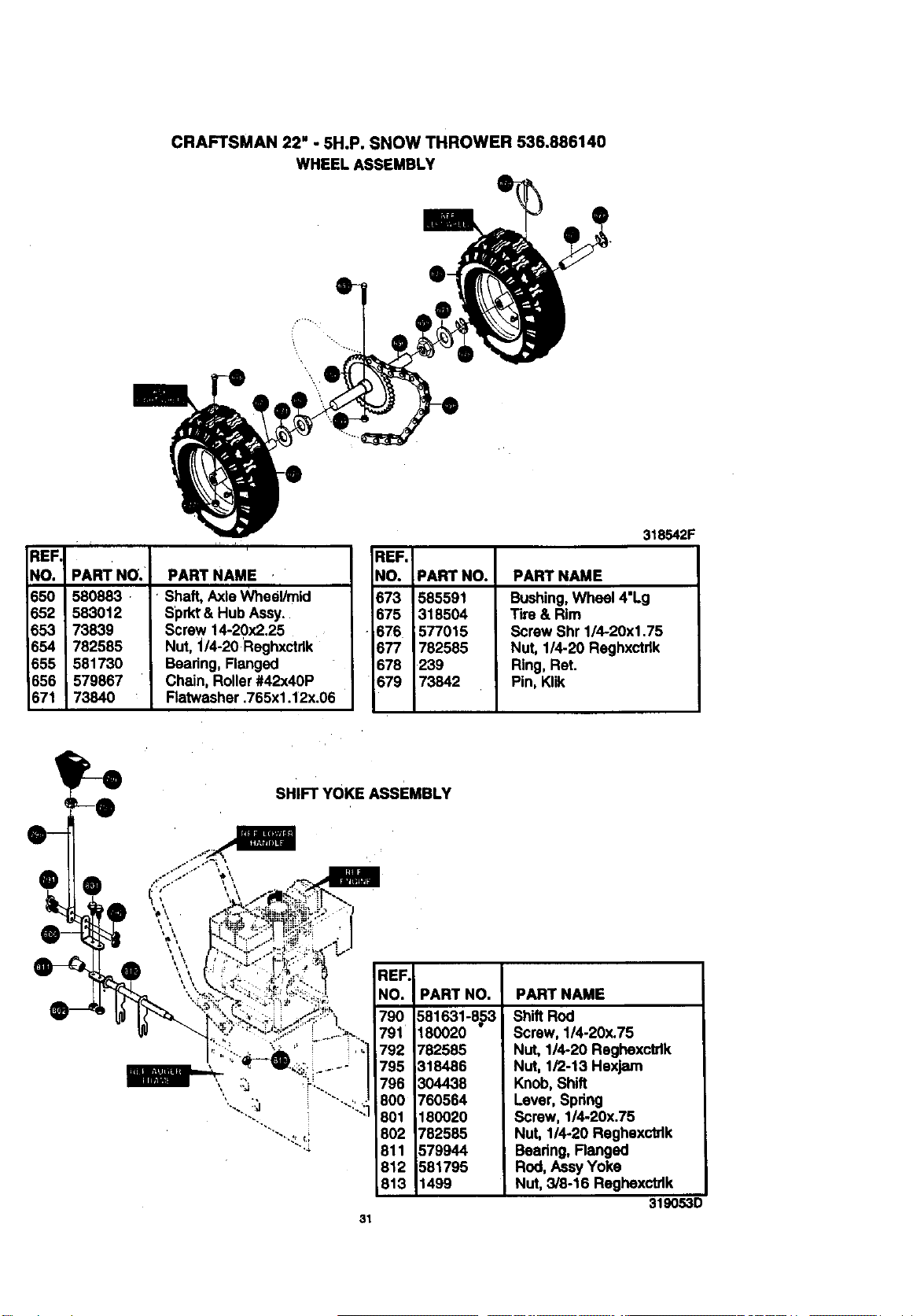
CRAFTSMAN 22" - 5H.P. SNOW THROWER 536.886140
WHEEL ASSEMBLY
EF.I
_O. ' PART NO.
_50 580883 r
852 583012
853 73839
654 782585
555 581730
656 579857
671 73840
i, ,
PART NAME
Shaft, AxleWheel/mid
Sprkt'& Hub Assy.
Screw 14-20x2.25
Nut, "J/4-20Reghxctdk
Bearing, Flanged
Chain, Roller#42x40P
Flatwasher .765x1.12x.06
REF.
NO. PART NO.
673 585591
675 318504
675 577015
677 782585
678 239
679 73842
318542F
PART NAME
Bushing,Wheel 4"Lg
Tire & Rim
ScrewShr 1/4.20xl .75
Nut, 1/4-20 Reghxctdk
Ring, Ret.
Pin, Klik
SHIFT YOKE AssEMBLY
REF.
".,,I NO. PART NO.
790 581631-853
791 180020
""_ " .... _ 1 792 782585
......./ 795318 6
,, ,.'_.,j _.. ...... .j 798 3044381O0 760564
......"_ : ...."_:] 801 180020
"'...:__.; 802 782585
"'_ 811 579944
812 581795
813 t499
PART NAME
Shift Rod
Screw, 1/4-20x.75
Nut, 114-20Reghexctrlk
Nut, 1/2-13 Hexjam
Knob,Shift
Lever, Spring
Screw, 1/4.20x.75
Nut, 1/4-20 Reghexctrlk
Bearing, Ranged
Rod, AssyYoke
Nut, 3/8-16 Reghexctdk
319053D
31
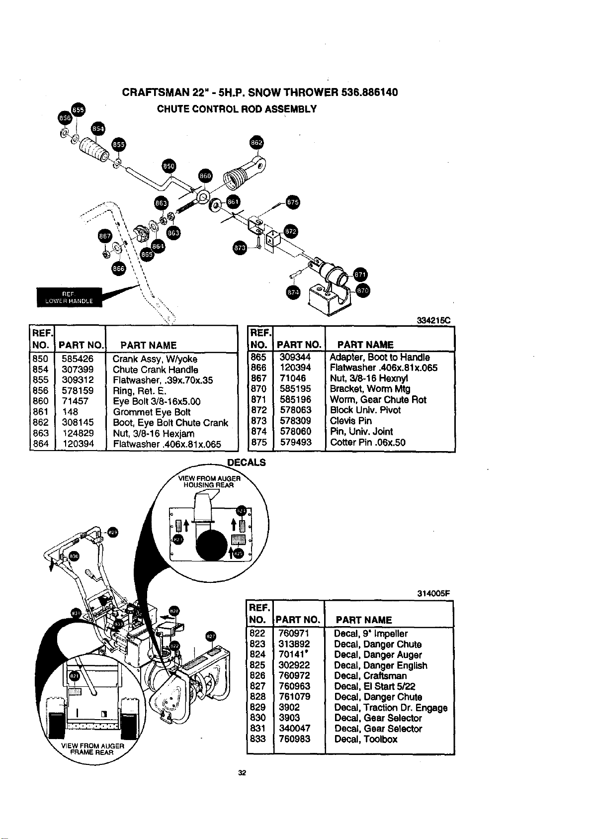
CRAFTSMAN 22" - 5H.P. SNOW THROWER 536.886140
CHUTE CONTROL ROD ASSEMBLY
REF
NO.
85O
854
855
856
860
661
862
863
864
PART NO.
585426
307399
309312
578159
71457
148
308145
124829
120394
PART NAME
Crank Assy, Whjoke
Chute Crank Handle
Flatwasher,.39x.70x.35
Ring,Ret. E.
Eye Bolt3/8-16x5.00
Grommet Eye Bolt
Boot,Eye BoltChute Crank
Nut,3/8-16 Hexjam
Flatwasher .406x.81x.065
REF.
NO.
865
866
867
870
871
872
873
874
875
DECALS
@
334215C
PART NO,
309344
120394
71046
585195
585196
578063
578309
578060
579493
PART NAME
Adapter, BoottoHandle
Flatwasher .406x.81x.065
Nut,3/8-16 Hexnyl
Bracket, Worm Mtg
Worm, Gear Chute Rot
BlockUniv. Pivot
Clevis Pin
Pin, Univ.Joint
Cotter Pin .06x.50
REF.
NO.
822
823
824
825
826
827
828
829
830
831
833
314005F
PART NO.
760971
313892
70141"
302922
760972
760963
761079
3902
3903
340047
760983
PART NAME
Decal, 9"impeller
Decal, Danger Chute
Decal, Danger Auger
Decal, Danger English
Decal, Craftsman
Decal, ElStart 5/22
Decal, Danger Chute
Decal, TractionDr. Engage
Decal, Gear Selector
Decal, Gear Selector
Decal, Toolbox
32
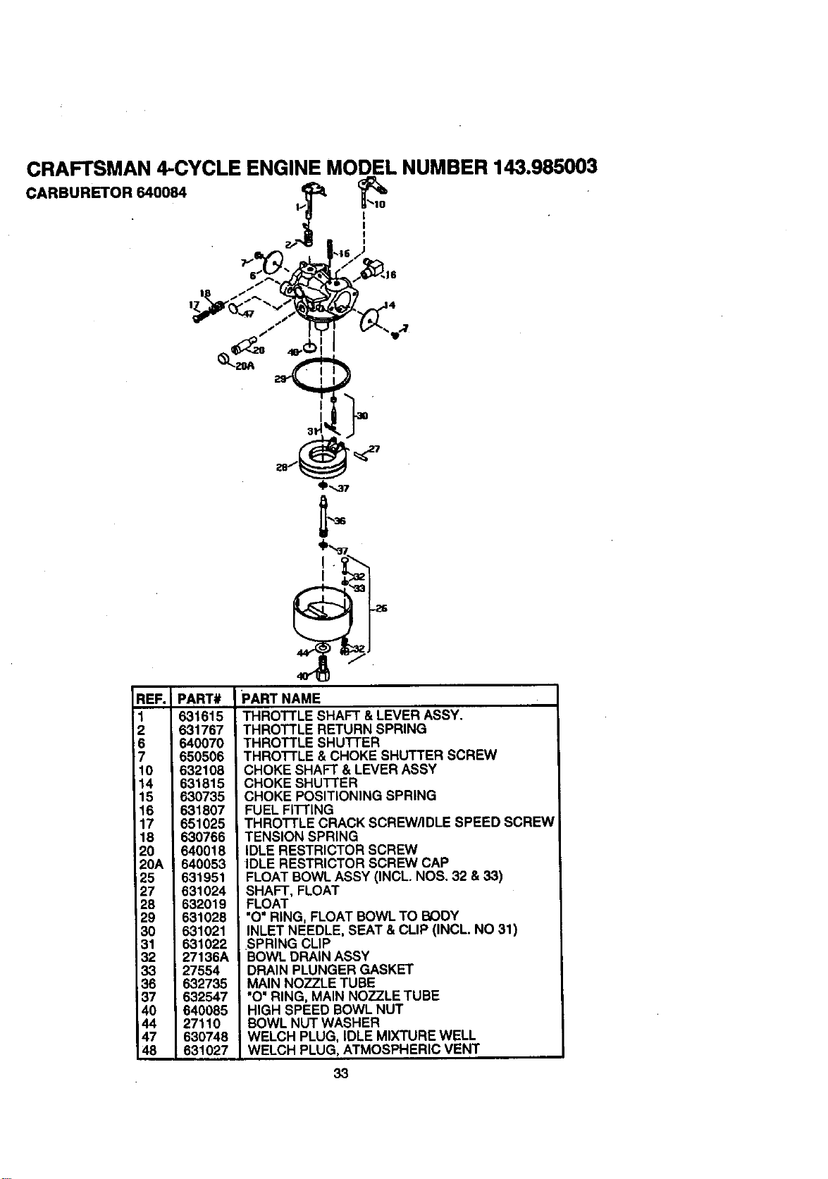
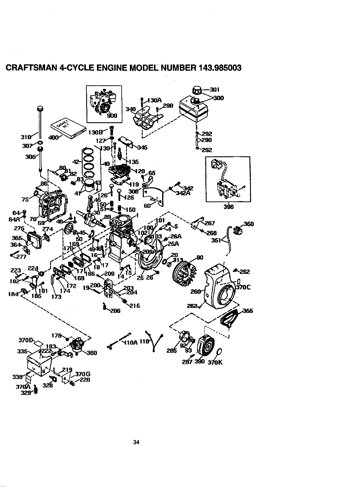
CRAFTSMAN 4-CYCLE ENGINE MODEL NUMBER 143.985003
CARBURETOR 640084 z_ _'''
REF.
1
2
_6
7
10
14
15
16
17
18
2O
20A
25
27
28
29
30
31
32
33
38
37
40
44
47
48
_D-,,,37
PART#
631615
331767
640070
650506
632108
631815
630735
631807
651025
630766
640018
640053
631951
631024
632019
631028
631021
631022
27136A
27554
632735
632547
640085
27110
630748
631027
PART NAME
THROTTLE SHAFT & LEVER ASSY.
THROTTLE RETURN SPRING
THROTTLE SHU'I-I'ER
THRO'I-I'LE & CHOKE SHUTTER SCREW
CHOKE SHAFT & LEVER ASSY
CHOKE SHUTTER
CHOKE POSITIONING SPRING
FUEL FITTING
THROTTLE CRACK SCREW/IDLE SPEED SCREW
TENSION SPRING
iDLE RESTRICTOR SCREW
IDLE RESTRICTOR SCREW CAP
FLOAT BOWL ASSY (INCL. NOS. 32 & 33)
SHAFT, FLOAT
FLOAT
"O' RING, FLOAT BOWL TO BODY
INLET NEEDLE, SEAT & CLIP (INCL. NO 31)
.SPRING CLIP
BOWL DRAIN ASSY
DRAIN PLUNGER GASKET
MAIN NOZZLE TUBE
"O' RING, MAIN NOZZLE TUBE
HIGH SPEED BOWL NUT
BOWL NUT WASHER
WELCH PLUG, IDLE MIXTURE WELL
WELCH PLUG, ATMOSPHERIC VENT
33
CRAFTSMAN 4-CYCLE ENGINE MODEE NUMBER 143.985003
>
34
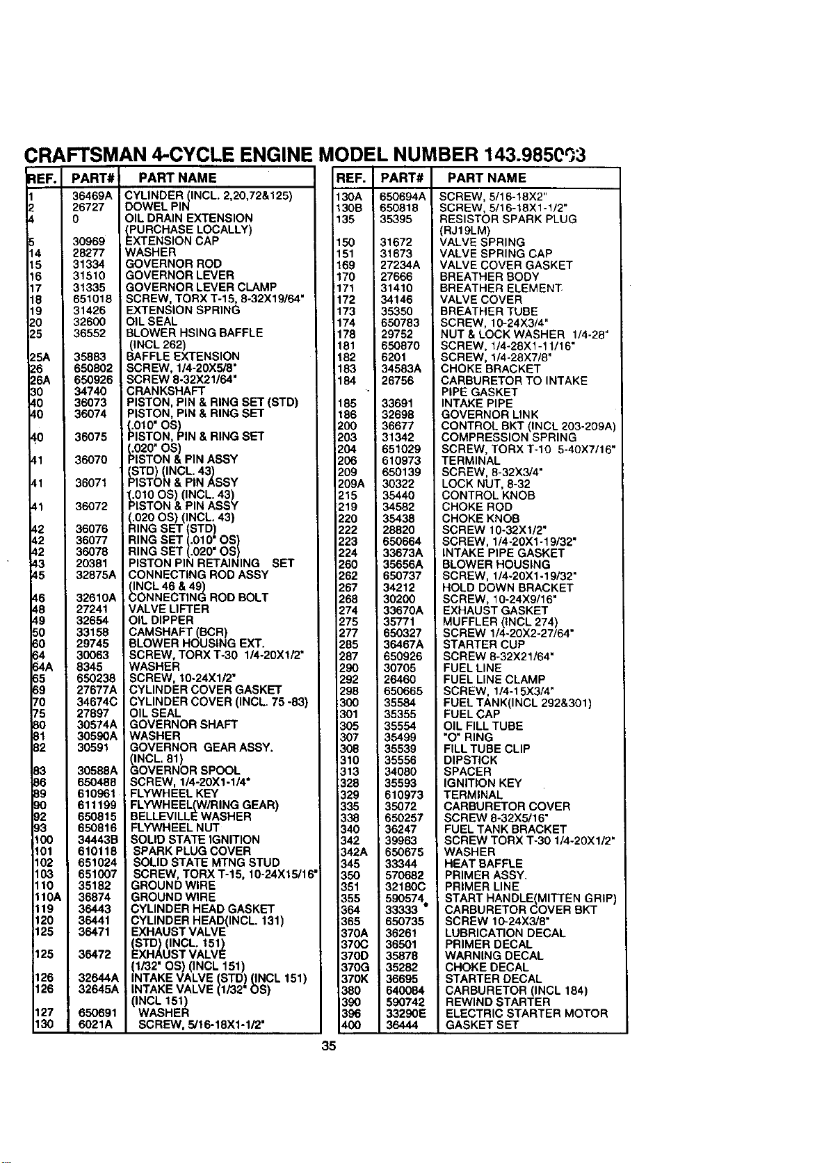
CRAFTSMAN 4-CYCLE ENGINE MODEL NUMBER 143.985Cq3
EF.
4
5
6
7
8
9
0
5
5A
6
6A
0
0
0
0
.1
,2
,2
_2
_3
_5
_6
_8
r9
_0
_0
;4
;4A
55
39
r0
r5
30
31
32
33
36
39
]0
)2
)3
100
101
102
103
110
I10A
119
120
125
125
126
126
127
130
PART# I
I
36469A I
_R727 I
30969 I
28277 I
31334 I
31335 I
651018 I
314_ I
32600 I
36552 I
35883 I
6508021
6509261
34740
36073
36074
36075
36070
36071
36072
36076
36077
36078
20381
32875A
32610A
27241
32654
33158
29745
30063
8345
650238
27677A
34674C
27897
30574A
30596A
30591
30588A
650488
610961
611199
650815
650816
34443B
610118
651024
651007
35182
36874
36443
36441
36471
36472
32644A
32645A
650691
6021A
PART NAME
CYLINDER INCL. 2,20,72&125)
DOWEL P N
OIL DRAIN EXTENSION
_PxURCHASELOCALLY)
TENSION CAP
WASHER
GOVERNOR ROD
GOVERNOR LEVER
GOVERNOR LEVER CLAMP
SCREW, TORX T-15, 8-32X19/64"
EXTENSION SPRING
OIL SEAL
BLOWER HSING BAFFLE
(INCL 262)
BAFFLEEXTENSION
SCREW, 1/4-20)(5/8"
SCREW 8-32X21/64"
CRANKSHAFT
PISTON, PIN & RING SET (STD)
PISTON, PiN & RING SET
_010" OS)
ISTON, PiN & RING SET
_.1020"OS)
STON & PIN ASSY
tSTD) (INCL. 43)
STON & PIN ASSY
_010 OS) (INCL. 43)
ISTON & PIN ASSY
_ION20OS) (INCL. 43)
G SET (STD)
RING SET (.010" OS)
RING SET (.020" OS)
PISTON PIN RETAINING SET
CONNECTING ROD ASSY
_NCL 46 & 49)
ONNECTING ROD BOLT
VALVE LIFTER
OIL DIPPER
CAMSHAFT (BCR)
BLOWER HOUSING EXT.
SCREW, TORX T-30 1/4-20X1/2"
WASHER
SCREW, 10-24X1/2"
CYLINDER COVER GASKET
CYLINDER COVER (INCL. 75 -83)
OIL SEAL
GOVERNOR SHAFT
WASHER
GOVERNOR GEAR ASSY.
(INCL. 61)
GOVERNOR SPOOL
SCREW, 1/4-20X1-1/4 °
FLYWHEEL KEY
FLYWHEEL(W/RING GEAR)
BELLEVILLE WASHER
FLYWHEEL NUT
SOLID STATE IGNITION
SPARK PLUG COVER
SOLID STATE MTNG STUD
SCREW, TORX T-15, 10-24X15/16'
GROUND WIRE
GROUND WIRE
CYLINDER HEAD GASKET
CYLINDER HEAD(INCL. 131)
EXHAUST VALVE
tSxTD (INCL. 151)
HAUST VALVE
(1/32" OS) 0NCL 151)
INTAKE VALVE (STD) (INCL 151)
INTAKE VALVE (1/32" OS)
(INCL 161)
WASHER
SCREW, 5/16-18X1-1/2"
:IEF. I
3oA I
30B
35
50
51
69
70
71
72
73
=74
178
181
_82
183
184
185
t86
->00
->03
->O4
->06
->09
->09A
->15
.>19
.>20
.>22
.>23
224
;=60
;=62
;=67
;=68
274
275
277
285
287
296
292
298
30O
301
3O5
307
308
310
313
328
329
335
338
340
342
342A
345
350
351
355
364
365
370A
370C
370D
370G
370K
380
390
396
4OO
PART#
650694A
650818
35395
31672
31673
27234A
27666
31410
34146
35350
650783
29752
650870
6201
34583A
26756
33691
32698
36677
31342
651029
610973
650139
30322
35440
34582
35438
;=8820
550664
33673A
35656A
850737
34212
30200
33670A
35771
650327
36467A
650926
30705
26460
650665
35584
35355
35554
35499
35539
35556
34080
35593
610973
35072
650257
36247
39963
650675
33344
570682
32180C
590574
33333 •
650735
36261
36501
35878
35282
36695
640084
590742
33296E
36444
PART NAME
SCREW, 5/16-16X2"
SCREW, 5/16-18X1-1/2"
RESISTOR SPARK PLUG
(RJ19LM)
VALVE SPRING
VALVE SPRING CAP
VALVE COVER GASKET
BREATHER BODY
BREATHER ELEMENT
VALVE COVER
BREATHER TUBE
SCREW, 10-24X3/4"
NUT & LOCK WASHER 1/4-28"
SCREW, 1/4-28X1-11/16"
SCREW, 1/4-28X7/8"
CHOKE BRACKET
CARBURETOR TO INTAKE
PIPE GASKET
INTAKE PIPE
GOVERNOR LINK
CONTROL BKT (INCL 203-209A
COMPRESSION SPRING
SCREW, TORX T-IO 5-40X7/16'
TERMINAL
SCREW, 8-32X3/4"
LOCK NUT, 8-32
CONTROL KNOB
CHOKE ROD
CHOKE KNOB
SCREW 10-32X1/2"
SCREW, 1/4-20X1-19/32"
INTAKE PIPE GASKET
BLOWER ROUSING
SCREW, 1/4-20X1-19/32"
HOLD DOWN BRACKET
SCREW, 10-24X9/16"
EXHAUST GASKET
MUFFLER (INCL 274)
SCREW 1/4-20X2-27/64"
STARTER CUP
SCREW 8-32X21/64"
FUEL LINE
FUEL LINE CLAMP
SCREW, 1/4-15X3/4"
FUEL TANK(INCL 292&301)
FUEL CAP
OIL FILL TUBE
"O" RING
FILL TUBE CLIP
DIPSTICK
SPACER
IGNITION KEY
TERMINAL
CARBURETOR COVER
SCREW 8-32X5/16"
FUEL TANK BRACKET
SCREW TORX T-30 1/4-20X1/2"
WASHER
HEAT BAFFLE
PRIMER ASSY•
PRIMER LINE
START HANDLE(MITTEN GRIP)
CARBURETOR COVER BKT
SCREW 10-24X3/8"
LUBRICATION DECAL
PRIMER DECAL
WARNING DECAL
CHOKE DECAL
STARTER DECAL
CARBURETOR (INCL 184)
REWIND STARTER
ELECTRIC STARTER MOTOR
GASKET SET
35
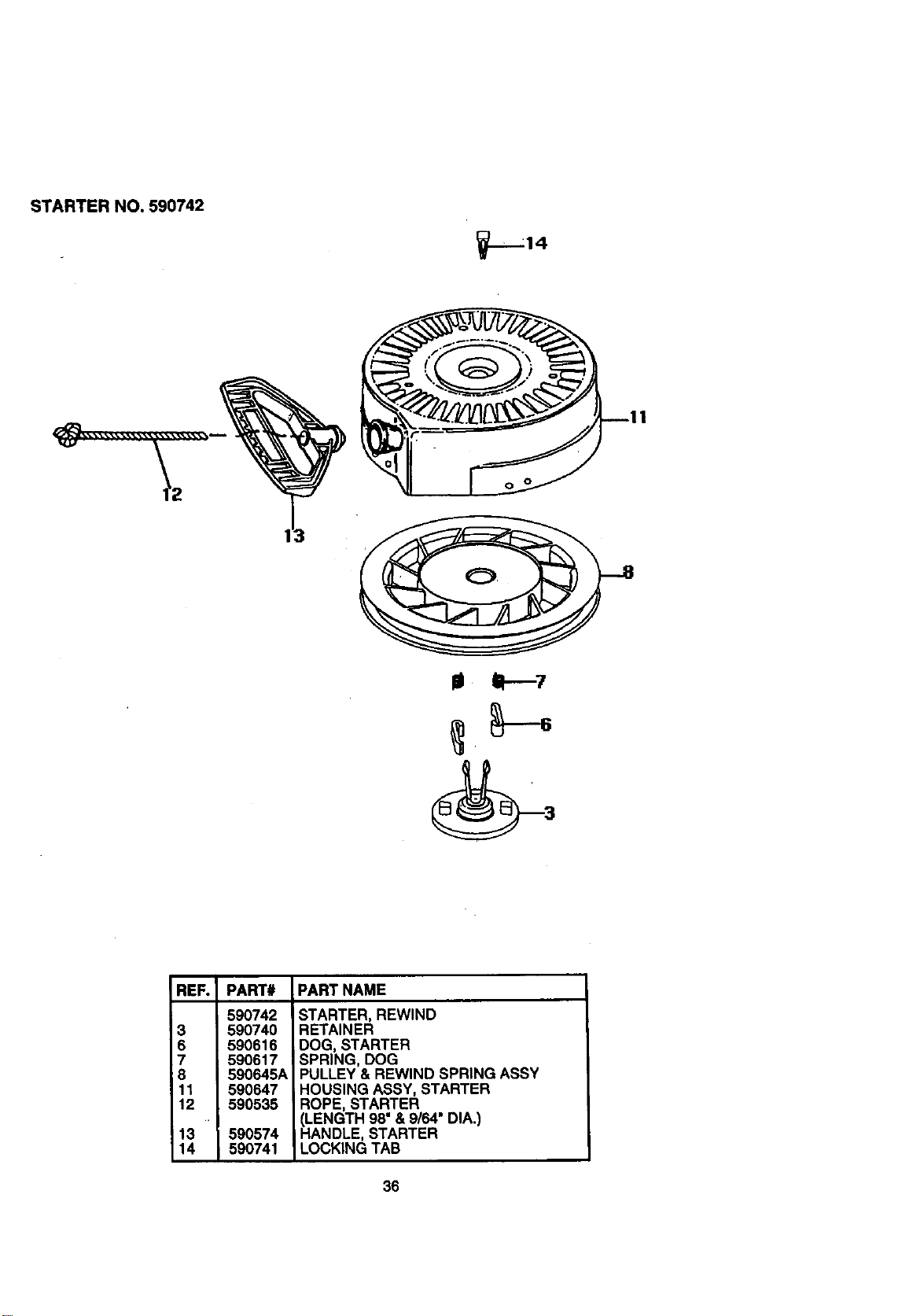
STARTER NO. 590742
REF. PART# PART NAME
590742
3 590740
6 590616
7 590617
:8 590645A
11 590647
12 590535
13 590574
14 590741
STARTER, REWIND
RETAINER
DOG, STARTER
SPRING, DOG
PULLEY & REWIND SPRING ASSY
IHOUSING ASSY, STARTER
ROPE, STARTER
(LENGTH 98"& 9/64"DIA.)
HANDLE, STARTER
LOCKING TAB
36
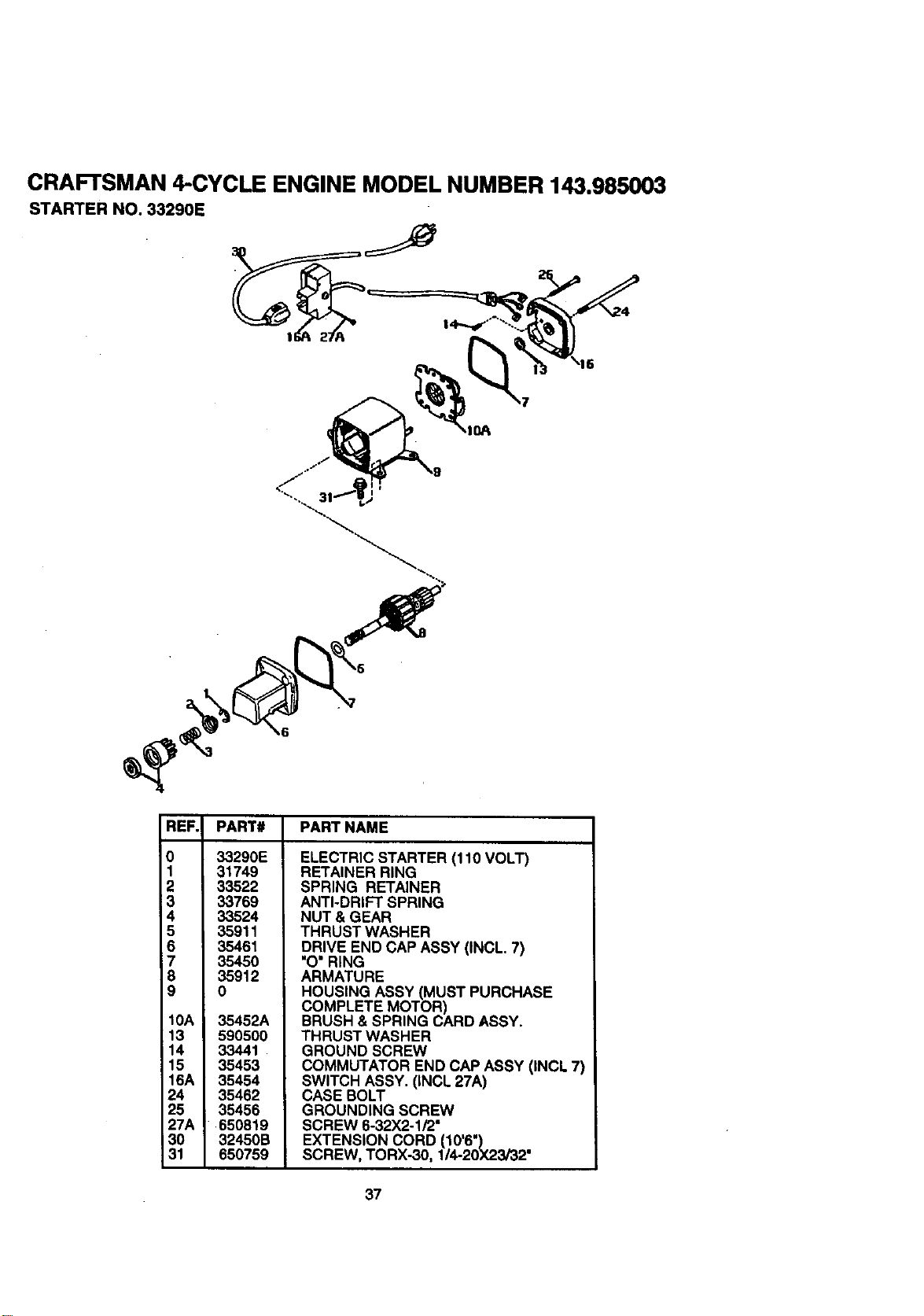
CRAFTSMAN 4-CYCLE ENGINE MODEL NUMBER 143,985003
STARTER NO. 33290E
REF. PART# PART NAME
0
1
2
3
4
5
6
7
8
9
10A
13
14
15
16A
24
25
27A
30
31
33290E
31749
33522
33769
33524
35911
35461
35450
35912
0
35452A
590500
33441
35453
35454
35462
35456
650819
32450B
650759
ELECTRIC STARTER (110 VOLT)
RETAINER RING
SPRING RETAINER
ANTI-DRIFT SPRING
NUT & GEAR
THRUST WASHER
DRIVE END CAP ASSY (INCL. 7)
"O"RING
ARMATURE
HOUSING ASSY (MUST PURCHASE
COMPLETE MOTOR)
BRUSH & SPRING CARD ASSY.
THRUST WASHER
GROUND SCREW
COMMUTATOR END CAP ASSY (INCL 7)
SWITCH ASSY. (INCL 27A)
CASE BOLT
GROUNDING SCREW
SCREW 6-32X2-1/2"
EXTENSION CORD (10'6")
SCREW, TORX-30, 1/4-20X23/32"
37

For the repair or replacement parts you
need delivered directly to your home
Call 7 am-7 pm, 7 days a week
1-800-366-PART
(1-800-366-7278)
Para ordenar piezas con entrega
a domicilio -1-800-659-7084
For in-house major brand repair service
Call 24 hours a day, 7 days a week
1-800-4-REPAIR
(1-800-473-7247)
Para pedir servicio de reparaci6n a
domicilio - 1-800-676-5811
For the location of a Sears Parts and
Repair Center in your area
Call 24 hours a day, 7 days a week
1-800-488-1222
"-----l-'lll
For information on purchasing a Sears
Maintenance Agreement or to inquire
about an existing Agreement
Call 9 am -5pm, Monday-Saturday
1-800-827-6655
When requesting service or ordering
parts, always provide the following
information:
° Product Type • Part Number
• Model Number • Part Description
America'sRepotSpecialists
Printed in U.S.A.


