OUTDOOR POST LIGHT
1. Pour cement base for the lamp.
2. Place anchor bolts into the cement with the base plate sitting on top of the
cement holding the bolts in proper position. Make sure the anchor bolts are
above the cement sufficiently to clear through the base when assembled. Make
sure the power supply passes through the centre hole of the base plate. (Note:
make sure the surface of the cement is level). After the cement is cured, proceed
with the next step.
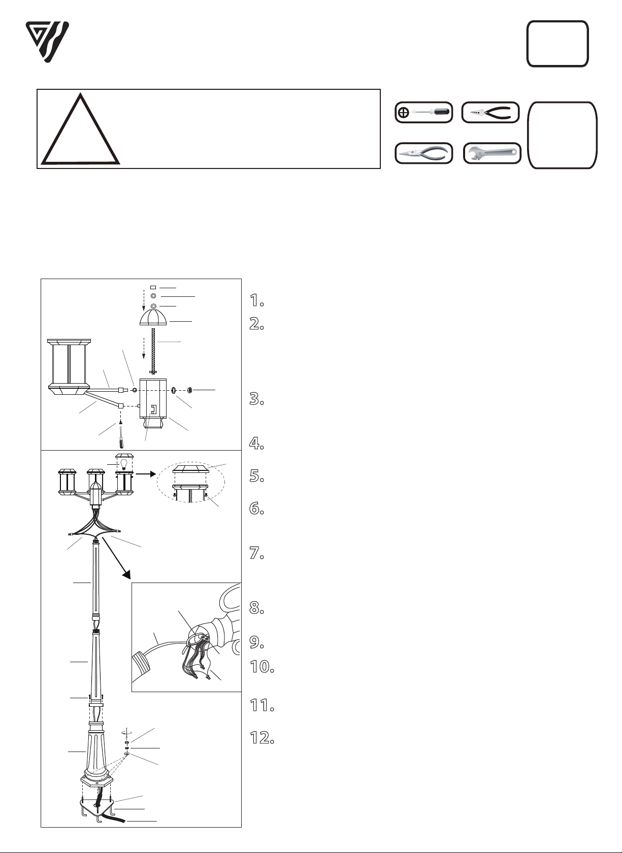
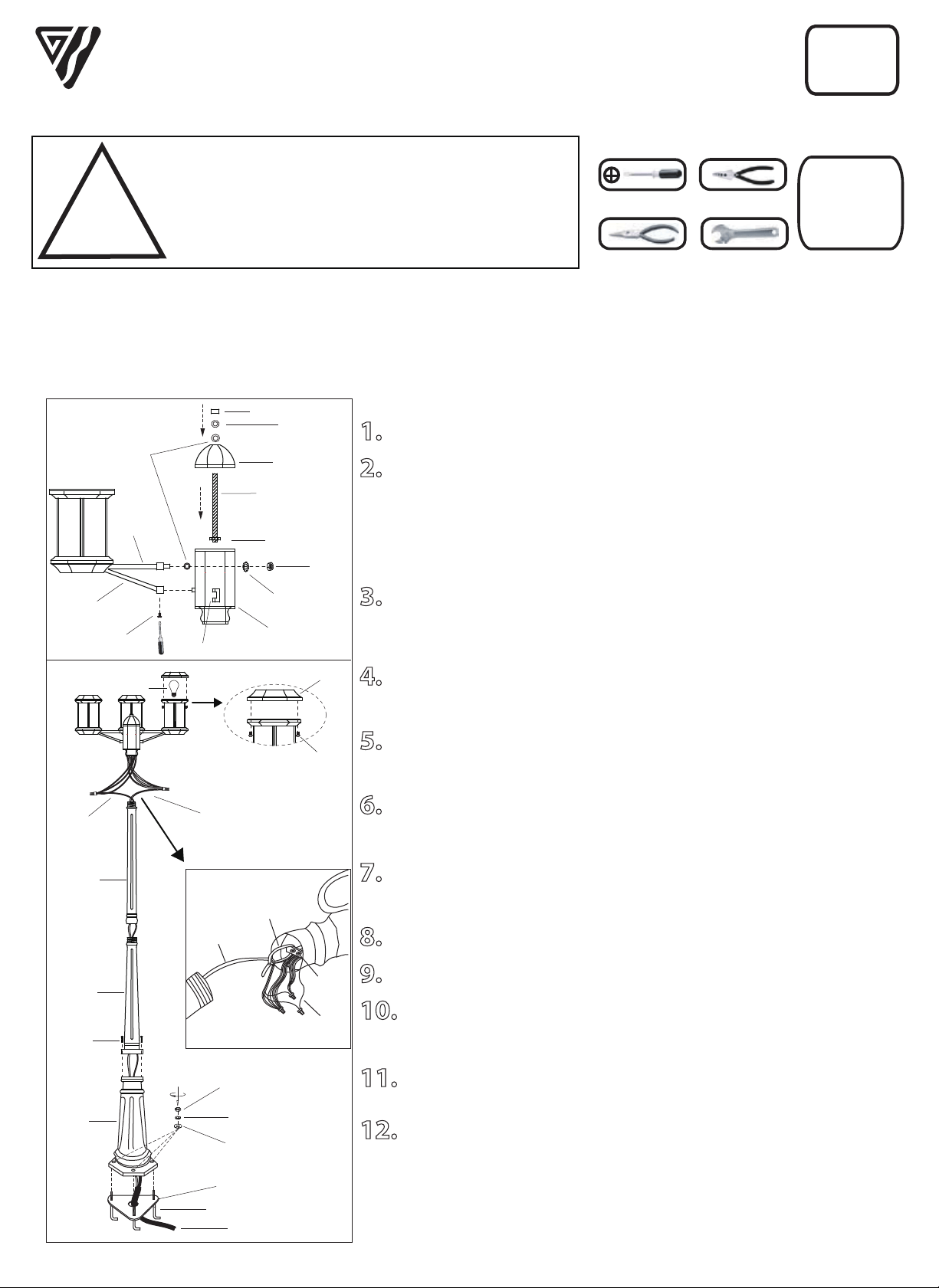
3. Assmble the three arms to the center post using the rubber gasket, hex nut
and lock washer for each of the top arm. Also, tighten the jam screw on each of
the bottom arm.
4. Screw the center nipple into the bracket in the center post and position top
cap in place. Secure them using the rubber gasket ,hex nut and finial.
5. Feed the power leads up through the base and bolt the base to the anchor
bolts using washers, locking nuts and anchor bolt nuts.
6. Feed the power supply through the lower post and upper post. Feed power
supply through the cable tie. Tighten the cable tie so that the power supply
tightens against the bar.
7. Connect the power supply to the head assembly. Attach the black wire to
the black wires. Attach the white wire to the white wires. Ground wire from
power supply should be attached to ground wire from bar inside the head
assembly.
8. Screw the upper post into the head assembly (be careful not to twist the
wires).
9. Screw the lower post into the upper post.
10. Set the assembled pieces (lower post, upper post & head assembly) onto
the base by tightening the 3 screws.
11. Install the proper bulb type and wattage (not included).
12. Install the cover to the head by tightening the 2 screws.
Upper
Post
Lower
Post
Base
Base Plate
Anchor Bolts
Power
White
Black
IOL349
IOL354
11/17
SAFETY PRECAUTIONS:
1. TURN OFF ELECTRICAL POWER BEFORE STARTING INSTALLATION OF LIGHT FIXTURE.
2. THIS PRODUCT MUST BE INSTALLED IN ACCORDANCE WITH THE APPLICABLE INSTALLATION
CODE BY A PERSON FAMILIAR WITH THE CONSTRUCTION AND OPERATION OF THE PRODUCT AND
THE HAZARDS INVOLVED.
Tel: (613) 342-5424, Fax: (800) 263-4598
Top Arm
Finial
Center Post
Bracket
Nut
Lock washer
Nut
Nut
Rubber Gasket
Rubber
Gasket
Center Nipple
Top Cap
Head Assembly
Jam
Screw
Bottom Arm
TOOLS AND MATERIALS REQUIRED:
Phillips
Screwdriver
Wire Cutters
Pliers Wrench
!
INSTRUCTIONS PERTAINING TO RISK OF FIRE OR INJURY TO PERSONS
READ ALL INSTRUCTIONS
IMPORTANT SAFETY
INSTRUCTIONS
SAVE THESE INSTRUCTIONS
QUESTIONS OR CONCERNS CONTACT AT:
1-800-265-1833 (English) / 1-800-567-2513 (French)
Monday through Friday 8:00 AM to 5:00 PM E.S.T.
Wiring supplies
as required by
local electrical
code
INSTALLATION:
Bar
Ground
Head Assembly
Upper
Post
Power
Supply
Cable tie
Anchor Bolt
Nuts
Locking Nut
Washer
Bulb
Screw
Screw
Cover
NOTE: Product may not look exactly as shown in figures.
IOL349
IOL354
11/17
ECLAIRAGE EXTERIEUR
1. Verser le ciment dans la base.
2. Posez les boulons dans le ciment et reposez la plaque de la base sur le
dessus tenant ainsi les boulons en position. Assurez-vous que les boulons
dÈpassent suffisament le ciment pour passer en travers de la base lorsque le tout
sera assemblé. Assurez-vous que le courant passe en travers du trou au centre de
la plaque de la base. (N.B.: Assurrez-vous que la surface du ciment en bien de
niveau). Après que le ciment ait durci quelque peu, procédez aux étapes
suivantes.
3. Assemblez les trois bras au poteau du centre à l’aide du joint d’étanchéité
en caoutchouc, l’écrou et la rondelle de blocage pour chacun des bras
supérieurs. Serrez également la vis de blocage sur le bras inférieur.
4. Visser le bout fileté du centre à la ferrure du poteau central et placer le
capuchon en place. Fixer à l’aide du joint en caoutchouc, de l’écrou hexagonal et
du fleuron.
5. Faufilez les fils de connexion en travers de la base et du boulon de la base
au boulons d'ancrage en utilisant les rondelles, les rondelles de blocage et les
écrous des boulons d'ancrage.
6. Faufilez les fils en travers du poteau inférieur et le poteau du haut. Faufilez
la source de courant en travers de l'attache en nylon. Serrez l'attache afin que le
cable soit serré contre la barre.
7. Branchez le courant à la tête. Posez le fil noir au fils noirs. Posez le fil blanc
au fils blancs.Le fil de la mise à terre de la source de courant devrait Ítre attaché
au fil de mise à terre sur la barre situé à l'intérieur de la tête.
8. Vissez le poteau du haut à la tête. (Attention de ne pas tordre les fils).
9. Vissez le poteau inférieur au poteau du haut.
10. Poser les pièces assemblées (poteau inférieur, poteau supérieur et tête
du moteur) sur la base en serrant les 3 vis.
11. Posez l'ampoule de type et de wattage requis (en sus).
12. Poser le couvercle à la tête en serrant les 2 vis.
Poteau
Inférieur
Blanc
Poteau
Du Haut
Noir
Base
Courant
Plaque De La Base
Boulons D’ancrage
Barre
Poteau
Supérieur
Source De
Courant
Attache En
Nylon
Mise A
Terre
MISE EN GARDE:
1. FERMEZ LE COURANT AU DISJONCTEUR AVANT DE DEBUTER L’INSTALLATION DE LA FIXTURE.
2. CE PRODUIT DOIT TRE INSTALLE SELON LE CODE D’INSTALLATION PERTINENT, PAR UNE PERSONNE
QUI CONNAIT BIEN LE PRODUIT ET SON FONCTIONNEMENT AINSI QUE LES RISQUES INHERENTS.
PH: (450) 665-2535, FX: (450) 665-0910
N.B.: Peut différer de illustration.
Tournevis A
Phillips
Coupeur De Fils
Pinces
Clef
!
INSTRUCTIONS CONCERNANT LE RISQUE
D’INCENDIES OU LES DOMMAGES CORPORELS
LISEZ TOUTES LES INSTRUCTIONS
INSTRUCTIONS DE SÛRETÉ
IMPORTANTES
GARDEZ CES INSTRUCTIONS
Fournitures
électriques telles
que prescrites
par les normes
locales
OUTILS ET MATERIAUX REQUIS:
QUESTIONS OU INFORMATION COMMUNIQUE AVEC AU:
1-800-265-1833 (Anglais) / 1-800-567-2513 (Français)
Du lundi au vendredi entre 8:00H et 17:00H H.N.E.
INSTALLATION:
Fleuron
Poteau
Du Centre
Ferrure
Ecrou
Ecrou
Joint
D’étanchéité
Bout Fileté
Capuchon
Rondelle
De Blocage
Tête
Tête
Vis De
Blocage
Bras Inférieur
Bras
Supérieurs
Écrou de Blocage
Ecrous De
Boulons D’ancrage
Rondelle
Ampoule
Ecrou
Vis
Vis
Couvercle

